MICROPROCESSOR RELAY FOR PROTECTION OF ELECTRICAL SYSTEMS
|
|
|
- Dwayne Young
- 6 years ago
- Views:
Transcription
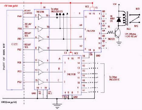
1 MICROPROCESSOR RELAY FOR PROTECTION OF ELECTRICAL SYSTEMS V.LALITH KUMAR, IV-EEE S.T.I.C, GARIVIDI, VZM DT. INTRODUCTION: Modern power systems have a high degree of reliability. Power system design together with proper operation and maintenance practices, decreases the probability of electrical failure but cannot exclude them completely. Hence a power system requires a real time embedded system, which operates within strict time deadlines. According to the type of electrical faults real time operations can be differentiated. In the first case, abnormal conditions like overloading of electrical equipment it is not always necessary to have quick operation of protective relaying. For such conditions slow real time operations are suitable. In the second case, electrical failures like short circuit fault causes excessive heating and damage of the equipment. So, this effect can be decreased by reducing the fault period, hence high speed real time operation is very desirable. MODELING OF MICROPROCESSOR BASED RELAY: Microprocessor based relay can also be referred to as numeric relays or Programmable relays. These relays are extensively used in industries. The main advantage of using this relay is its capability of replacing all specific purpose relays by a single microprocessor based relay can be used for protection against various faults like over current, over voltage, thermal overload etc by just modifying the program. Relay Driver Interface circuit: This 8085 kit based interface circuit controls 64 relays. The 8085 kit has 8255 programmable peripheral interface IC, whose ports have been extended via suitable connectors. The 8255 have been configured for mode 0 operation. Ports A, B and C of 8255 are configured as output ports using control word 80hex. The various outputs of 8255 after buffering by 74LS244 are used as follows:
2 PA0: Connected to pin 13 of IC 74LS259 for relay switching (Logic1 for on and logic0 for off ) PB0, PB1, PB2: As address for IC to select up to eight different relay numbers. PC0, PC1, PC2: As address for IC to select up to eight different IC The interface circuit comprises of 1-of-8 demultiplexer IC74138, octal buffer / driver IC74244 and IC74259 (configured here as 8 bit addressable latch). The supply for these IC s is taken from the 8085 kit itself. For relays, an external 12V supply is used. Octal buffer IC has open collector outputs. It is used as a buffer for outputs from 8255.The relay on/off information available PA0 pin of port A is used as data input at pin 13 of IC The three bits PB0 through PB2 are used as 3-bit address for IC IC is used here in 8-bit addressable latch mode. In this mode the data at its pin 13 corresponds to the data for the selected output (1= on 0= off ). The remaining outputs are not effected and stay in their previous state, so the other relays controlled by these pins are not affected. The 3-bit data at PC0 through PC2 are used as a 3-bit address for 1-0f-8 multiplexer IC The output at pin 15 is used as chip select line for IC Similarly, it is possible to connect the remaining seven outputs as chip select lines for other seven ICs. So a total of 64 relays can be controlled. The relays are controlled via relay driver transistors 2N2222.If the input voltage to the base is low, the transistor remains turned off, while logic 1 output activates the relay. A diode in parallel with the relay coil protects the transistor from the high voltage induced in the relay coil during its turn-off period. When the 8085 program for relay selection is executed in the kit, the display shows code. Enter the code (1 for switching on of relay and 0 for switching it off) and press next. Now the display shows num. Enter the relay number (from 00 to 64 can be used if all ICs and relays are in place) and press next. The corresponding relay will be activated, with the relay number also displayed in the kit. For addressing peripheral devices the I/O mapped address scheme is employed in the kit. The ckt diagram is shown in fig 1. Feedback circuit for over voltage protection: The feedback interface circuit as shown in figure2 is used to sense over voltages and send corresponding signals as inputs to the microprocessor. It comprises of a diode bridge (800V, 6A). A capacitor (1000uf, 63V) which is used to filter D.C output, a comparator IC LM 393.External +5V supply is given to thin IC. Two such circuits are used
3 for over voltage protection of two loads. The load used is a resistive load (24V A.C bulb). The feedback is taken from the input. The feedback A.C voltage is given to the diode bridge, which rectifies the variable A.C voltage to the variable D.C voltage. This variable is filtered using a capacitor of rating 1000uf; 63v.A 670W resistor is used across the capacitor for fast discharging of the variable D.C voltage. The rectified D.C output is dropped to the required value using a variable resistor (10kW). A comparator LM 393 is used to compare the variable D.C voltage with a reference voltage. If the variable D.C voltage exceeds the reference voltage the output goes high else it remains in the low state. The feedback circuit connected to the second load works in the same manner. Now, the outputs of both the comparators are given as inputs to IC. The outputs of this IC are given as inputs to the microprocessor through 8255 programmable peripheral interface IC. Testing of relay for two loads: Probable conditions for occurrence of fault: Legend: N-normal operation. F -fault. LOAD 1 LOAD 2 N N N F F N F F This relay works for all above conditions in any sequence for any number of times. To test the functionality of the relay an over voltage fault was created using an autotransformer. The inputs of the IC (from the comparator LM 393) and the outputs of this IC are shown in the following table. These outputs act as inputs to the microprocessor. The microprocessor produces the corresponding output to the relay driver circuit, which in turn disconnects the load from the source. INPUT OUTPUT He F bf df ef FLOWCHARTS: Instantaneous tripping: The logic for the instantaneous tripping is shown by the flowchart.
*count. Time delay for 100 ms: 100mS = 21*.")
4 Time delay tripping: Delay calculations: The time delay in the loop TL with MHz clock frequency is calculated as TL=(T*loop T -states*n10). Where TL = time delay in the loop. T = system clock period. N10 = equivalent decimal numbers of the hexadecimal count loaded in the delay register. TL = 21 T-states T (clock period)*count. Time delay for 100 ms: 100mS = 21*.325*10e-6*count. Count = 393C(Hex). RESULTS: This paper presents two modules. The first module consisted of the design, fabrication and testing of the relay driver interface circuit and also the development of program for control of 64 relays. At the end of each phase, it was necessary to obtain switching of relays depending upon the input conditions given, i.e. 00 for relay turn-off, 01 for turn- on of the relay and the corresponding relay number. The first module has been designed, fabricated and tested for the above output. The second module consisted of the design, fabrication and testing of the feedback circuit, which was connected to the relay driver interface circuit and the development of program for over voltage protection. At the end of this phase it was necessary to disconnect any of the loads instantaneously if the voltage exceeds the predetermined value. The second module has been designed, fabricated and tested for the above output. The output is also verified for time delay tripping.
5 FIGURE 1:
6 FIGURE 2: CONCLUSION:

7 The first module was constructed and tested for control of 64 relays. This module was interfaced with 8085 microprocessor and the program was executed successfully. The second module that contained the feedback circuit in addition to relay driver interface circuit was also fabricated and tested. The relays were successfully operated for over voltages. There is a lot of scope for further development of this module. The above circuit can be used for sensing various faults by changing the logic of the program accordingly. REFERENCES: 1.Microprocessor architecture, programming and applications, by Ramesh. S. Gaonkar; new age international publishers, 2nd Edition 2.Microprocessor programming and interfacing, Doughlas V. Hall, TMH publications. 3.Advanced Microprocessors and peripherals, A.K.Ray, K.M.Bhurchandi TMH publications. Ubiquity -- Volume 7, Issue 20 (May 24, May 31, 2006)
8
Review of Ultra Fast Acting Electronic Circuit Breaker at Overloading
 Review of Ultra Fast Acting Electronic Circuit Breaker at Overloading Lalit Kumar Sahu 1, Avanjelin Tirkey 2, Amit Kumar 3 1, 2,3 UG Student, Dept. of EEE, Government Engineering College, Raipur, Chhattisgarh,
POWER SAVER METER USING MICROCONTROLLER TO SAVE ELECTRICITY UPTO 30-40%
 POWER SAVER METER USING MICROCONTROLLER TO SAVE ELECTRICITY UPTO 30-40% Prof. Dipesh. M.Patel 1 Kandarp mehta 2 Himanshu amrutiya 3 Ravi bhalodia 4 Chirag amrutiya 5 1. Head, Electrical Engg. Department,
3 PHASE FAULT ANALYSIS WITH AUTO RESET FOR TEMPORARY FAULT AND TRIP FOR PREMANENT
 e-issn 2455 1392 Volume 3 Issue 4, April 2017 pp. 80 84 Scientific Journal Impact Factor : 3.468 http://www.ijcter.com 3 PHASE FAULT ANALYSIS WITH AUTO RESET FOR TEMPORARY FAULT AND TRIP FOR PREMANENT
SRI-02 Speech Recognition Interface
 SRI-02 Speech Recognition Interface Data & Construction Booklet The Speech Recognition Interface SRI-02 allows one to use the SR-07 Speech Recognition Circuit to create speech controlled electrical devices.
Basic I/O Interface
 Basic I/O Interface - 8255 11 3 THE PROGRAMMABLE PERIPHERAL 82C55 programmable peripheral interface (PPI) is a popular, low-cost interface component found in many applications. The PPI has 24 pins for
SECURITY FOR ORGANIZING GSM DIGITAL NOTICE BOARD Dr. Sreeja Mole S S 1, D.Gurunath 2, Yasmeen 3
 SECURITY FOR ORGANIZING GSM DIGITAL NOTICE BOARD Dr. Sreeja Mole S S 1, D.Gurunath 2, Yasmeen 3 1 Professor/HOD, Department of ECE, CJITS, Janagon. 2 Assistant Professor, CJITS, Janangon 3 CJITS, Janagon
ELECTRIC LINEMAN PROTECTION USING USER CHANGEABLE PASSWORD BASED CIRCUIT BREAKER 1
 ELECTRIC LINEMAN PROTECTION USING USER CHANGEABLE PASSWORD BASED CIRCUIT BREAKER 1 J.Veena, 2 G.Srivani, 3 Afreen, 4 M.Sunil Kumar, 5 J.Santhosh, 6 K.B.V.S.R.Subrahmanyam 1,2,3,4,5 BE Students, 6 Associate
Password Based Circuit Breaker
 Password Based Circuit Breaker Jay Kumar, Surya Kumar, Vivek Yadav, Naveen Kr. Singh, Prashant Kr. Gaur, Praveen Kr. Tyagi Department of Electrical Engineering, RBS Engineering Technical Campus, Agra,
ES-362U PRESETTABLE MASTER TIMER
 142 SIERRA ST., EL SEGUNDO, CA 90245 USA (310)322-2136 FAX (310)322-8127 www.ese-web.com ES-362U PRESETTABLE MASTER TIMER OPERATION AND MAINTENANCE MANUAL The ES-362U is a four digit, presettable 100 minute
Voltage surge suppressor
 Sheet 1 PRODUCT DESCRIPTION AC/DC converter are used to rectify the line supply voltage for the DC link, normally are used uncontrolled or controlled rectifier without or with regenerative feedback unit.
D115 The Fast Optimal Servo Amplifier For Brush, Brushless, Voice Coil Servo Motors
 D115 The Fast Optimal Servo Amplifier For Brush, Brushless, Voice Coil Servo Motors Ron Boe 5/15/2014 This user guide details the servo drives capabilities and physical interfaces. Users will be able to
Home Security System with Remote Home Automation Control
 Home Security System with Remote Home Automation Control Justin Klumpp Senior Project Hardware Description Western Washington University April 24 2005 Professor Todd Morton Introduction: This document
4. CIRCUIT BREAKERS. Functional Emergency Switching
 4. CIRCUIT BREAKERS The circuit breaker/disconnector fulfils all of the basic switchgear functions, while, by means of accessories, numerous other possibilities exist. As shown in table H2-19 the circuit
ECE 372 Microcontroller Design
 !! "! E.g. Port A, Port B "! Used to interface with many devices!! Switches!! LEDs!! LCD!! Keypads!! Relays!! Stepper Motors "! Interface with digital IO requires us to connect the devices correctly and
Installation/assembly manual for DCC/Power shield
 Installation/assembly manual for DCC/Power shield The DCC circuit consists of the following components: R1/R6 R2/R3 R4/R5 D1 C2 2 kω resistor ½ Watt (colour code Red/Black/Black/Brown/Brown) 10 kω resistor
Lecture-9 Intel 8085 Microprocessor It is a 40-pin DIP(Dual in package) chip, base on NMOS technology, on a single chip of silicon.
 chip, base on NMOS technology, on a single chip of silicon.") Lecture-9 Intel 8085 Microprocessor It is a 40-pin DIP(Dual in package) chip, base on NMOS technology, on a single chip of silicon. It requires a single +5v supply between Vcc at pin no 40 and GND at pin
Lecture-9 Intel 8085 Microprocessor It is a 40-pin DIP(Dual in package) chip, base on NMOS technology, on a single chip of silicon. It requires a single +5v supply between Vcc at pin no 40 and GND at pin
UNIT 3 THE 8051-REAL WORLD INTERFACING
 UNIT 3 THE 8051-REAL WORLD INTERFACING 8031/51 INTERFACING TO EXTERNAL MEMORY The number of bits that a semiconductor memory chip can store is called chip capacity It can be in units of Kbits (kilobits),
RMV ELECTRONICS INC. Application Note
 RMV ELECTRONICS INC. Application Note Description: Using more than one ITC232-A on the same Serial Port Application #: 00023 Date: May 1994 Status: Final Version This App note has been super-seeded by
Overvoltage Protection in Automotive Systems
 HOME PRODUCTS SOLUTIONS DESIGN APPNOTES SUPPORT BUY COMPANY MEMBERS App Notes > CIRCUIT PROTECTION SENSOR SIGNAL CONDITIONERS APP 760: Jun 18, 2001 Keywords: overvoltage, over voltage, protection, automotive,
MICRO BURN IN PRODUCTS LISTED IN MODEL NUMBER ORDER FOLLOWED BY A BRIEF DESCRIPTION
 MICRO BURN IN PRODUCTS LISTED IN MODEL NUMBER ORDER FOLLOWED BY A BRIEF DESCRIPTION MODEL 102P 102R DESCRIPTION Floor Stand (Plane) Floor Stand (Modified) HTRB Burn-In System (diode) Component Burn-In
Installation Instructions
 Installation Instructions This document provides information on: important pre-installation considerations power supply requirements initial handling procedures installing the module using the module indicators
ICTD-100CP / ICTD-101CP ICTD-102CP / ICTD-103CP
 PATENT PENDING ICTD-100CP / ICTD-101CP ICTD-102CP / ICTD-103CP Capacitor Trip Devices with Contact Protect Technology TM Operation Manual and Data sheet 2015 Intermountain Electronics, Inc. Important Notice
TD62M8600FG TD62M8600FG 8CH LOW SATURATION VOLTAGE SOURCE DRIVER FEATURES SCHEMATICS PIN CONNECTION (TOP VIEW)
") TOSHIBA BIPOLAR DIGITAL INTEGRATED CIRCUIT MULTI CHIP TD62M8600FG TD62M8600FG 8CH LOW SATURATION VOLTAGE SOURCE DRIVER TD62M8600FG is Multi Chip IC incorporates 8 low saturation discrete transistors equipped
TOSHIBA BIPOLAR DIGITAL INTEGRATED CIRCUIT MULTI CHIP TD62M8600FG TD62M8600FG 8CH LOW SATURATION VOLTAGE SOURCE DRIVER TD62M8600FG is Multi Chip IC incorporates 8 low saturation discrete transistors equipped
CHAPTER MAINTENANCE AND TROUBLESHOOTING. In This Chapter... Maintenance and Inspection Troubleshooting...6 3
 CHAPTER MAINTENANCE AND 6 TROUBLESHOOTING In This Chapter... Maintenance and Inspection..........................6 2 Monthly Inspection...................................6 2 Annual Inspection....................................6
DEV-1 HamStack Development Board
 Sierra Radio Systems DEV-1 HamStack Development Board Reference Manual Version 1.0 Contents Introduction Hardware Compiler overview Program structure Code examples Sample projects For more information,
ES-562/564U COMBINATION CLOCK/TIMER
 142 SIERRA ST., EL SEGUNDO, CA 90245 USA (310)322-2136 FAX (310)322-8127 www.ese-web.com ES-562/564U COMBINATION CLOCK/TIMER OPERATION AND MAINTENANCE MANUAL The ES-562U/564U is a combination six digit
12v Power Controller Project Board
 12v Power Controller Project Board 12 Volt Power Controller Introduction This board provides three functions... DC power gate Low voltage disconnect Voltage / current display The typical usage for this
PCL channel Isolated Digital I/O Card
 PCL-730 32-channel Isolated Digital I/O Card Copyright This documentation is copyrighted 1996 by Advantech Co., Ltd. All rights are reserved. Advantech Co., Ltd. reserves the right to make improvements
CREATED BY M BILAL & Arslan Ahmad Shaad Visit:
 CREATED BY M BILAL & Arslan Ahmad Shaad Visit: www.techo786.wordpress.com Q1: Define microprocessor? Short Questions Chapter No 01 Fundamental Concepts Microprocessor is a program-controlled and semiconductor
CHAPTER 5. Voltage Regulator
 CHAPTER 5 Voltage Regulator In your robot, the energy is derived from batteries. Specifically, there are two sets of batteries wired up to act as voltage sources; a 9V battery, and two 1.5V batteries in
Motor driver board. EB022
 Motor driver board www.matrixmultimedia.com EB022 Contents About this document 3 Board layout 3 General information 4 Circuit description 5 Circuit diagram 6 2 Copyright About this document This document
Table of Contents. 1 General 1.1 Scope
 Table of Contents 1 General 1.1 Scope 2 Input Characteristics 2.1 Input Voltage 2.2 Input Frequency 2.3 Max. Input AC Current 2.4 Inrush Current 2.5 Efficiency 3 Output characteristics 3.1 Nominal Operation
The PCI Series. Precise power control for complex SCR applications. Phase Angle Fired SCR Power Controls AMPS VAC
 The PCI Series Phase Angle Fired SCR Power Controls 25-1200 AMPS 120-600 VAC Precise power control for complex SCR applications. ROBICON 1996 Distributed Worldwide by www.mcgoff-bethune.com Applications
UNIT V MICRO CONTROLLER PROGRAMMING & APPLICATIONS TWO MARKS. 3.Give any two differences between microprocessor and micro controller.
 UNIT V -8051 MICRO CONTROLLER PROGRAMMING & APPLICATIONS TWO MARKS 1. What is micro controller? Micro controller is a microprocessor with limited number of RAM, ROM, I/O ports and timer on a single chip
PCM ch Isolated Digital I/O Module. User Manual
 PCM-3730 32-ch Isolated Digital I/O Module User Manual Copyright The documentation and the software included with this product are copyrighted 2005 by Advantech Co., Ltd. All rights are reserved. Advantech
HDS Series I2C Application Notes
 HDS Series I2C Application Notes I2C Bus Interface Introduction The I2C interface of the HDS series of power supplies allows remote control and monitoring and provides the following features: 1) Retrieving
Latch-Up. Parasitic Bipolar Transistors
 Latch-Up LATCH-UP CIRCUIT Latch-up is caused by an SCR (Silicon Controlled Rectifier) circuit. Fabrication of CMOS integrated circuits with bulk silicon processing creates a parasitic SCR structure. The
CIRCUIT BREAKER TYPE DISCONNECTOR for OVERVOLTAGE PROTECTOR
 CIRCUIT BREAKER TYPE DISCONNECTOR for OVERVOLTAGE PROTECTOR HITOSHI KIJIMA MASAO SHIBAYAMA Electrical Department Polytechnic University 4-1-1 Hashimotodai Sagamihara 229-1196 Kanagawa JAPAN hkijima@uitec.ac.jp*
ElectronFlux USB Module
 ElectronFlux USB Module Product ID. : 800 Board Rev. : 1.00 Date : Mar 28, 2008 Firmware Rev. : 1.10 Node Firmware Rev. : 1.30 Beta Innovations Inc. (c) 2006-2008 http://www.betainnovations.com Table of
TOPIC 6 LATCH. FIGURE 1 INTERFACING OF ROM/EPROM TO µc 8051.
 TOPIC 6 MEMORY AND I/O INTERFACING MEMORY INTERFACING i. External ROM (program memory) Interfacing P1 P0 D 0-D 7 P3 EA clock LATCH A 0 ROM/ A 7 EPROM A 8 Address lines A 15 PSEN OE FIGURE 1 INTERFACING
DTMF BASED HOME AUTOMATION
 DTMF BASED HOME AUTOMATION Vimlesh Kumar Agrahari 1, Md Arzoo 2, Harish Kumar 3 1, 2 Students, Electrical Engineering Department Greater Noida Institutes of Technology, Gr.Noida, (India) 3 Assistant Professor,
Microcontroller-based under and over voltage protection device
 American Journal of Engineering Research (AJER) e-issn: 2320-0847 p-issn : 2320-0936 Volume-7, Issue-8, pp-16-20 www.ajer.org Research Paper Open Access Microcontroller-based under and over voltage protection
Effective Load Shedding Technique for Utility Department
 Volume-6, Issue-2, March-April 2016 International Journal of Engineering and Management Research Page Number: 334-337 Effective Load Shedding Technique for Utility Department Ankit Vijayvargiya 1, Abhishek
Embedded Systems and Software
 Embedded Systems and Software Lecture 12 Some Hardware Considerations Hardware Considerations Slide 1 Logic States Digital signals may be in one of three states State 1: High, or 1. Using positive logic
Description and Application Manual for 2SB315B SCALE Dual-Channel Plug-and-play IGBT Drivers
 for 2SB315B SCALE Dual-Channel Plug-and-play IGBT Drivers Driver solution for 130mm x 140mm dual IGBT modules with fiber-optic interface for 2-level topologies Abstract The 2SB315B is a dual-channel driver
18805 Adams Ct., #110 ~ Morgan Hill, CA 95037, USA ~ ~ ~
 1 of 8 WASHLINK SYSTEMS Yaskawa V1000 Basic User Guide This document provides basic information for navigating and adjusting your Washlink Systems supplied Yaskawa V1000 Variable Frequency Drive. When
4X4 Driver Shield Manual
 3/31/2012 4X4 Driver Shield Manual High current, high side switching for Arduino Logos Electromechanical 4X4 Driver Shield Manual High current, high side switching for Arduino Introduction The Logos Electromechanical
AUTOMOBILE APPLICATIONS USING CAN PROTOCOL
 AUTOMOBILE APPLICATIONS USING CAN PROTOCOL 1 VEERESH B M, 2 JEEVAN C N, 3 MAHESH PATIL 1,2,3 Department of Electronics and Communication, G.S.S.I.T, Bangalore, India Abstract- The main objective of the
USB board Mk2 INSTRUCTION MANUAL
 USB board Mk2 INSTRUCTION MANUAL Revision 0, December 2017 This manual comprises introducing information on use and performance of this device. For more information please refer to the Audial web site,
EC4205 Microprocessor and Microcontroller
 EC4205 Microprocessor and Microcontroller Webcast link: https://sites.google.com/a/bitmesra.ac.in/aminulislam/home All announcement made through webpage: check back often Students are welcome outside the
Professional Radio GM Series. Controlhead Service Information
 Professional Radio GM Series Controlhead Service Information Issue: September 2000 ii Computer Software Copyrights The Motorola products described in this manual may include copyrighted Motorola computer
Images Scientific OWI Robotic Arm Interface Kit (PC serial) Article
 Article") Images Scientific OWI Robotic Arm Interface Kit (PC serial) Article Images Company Robotic Arm PC Interface allows real time computer control and an interactive script writer/player for programming and
Images Scientific OWI Robotic Arm Interface Kit (PC serial) Article Images Company Robotic Arm PC Interface allows real time computer control and an interactive script writer/player for programming and
6R MATRIX Pre-Defined. Modular Relays. rms. Auxiliary, Trip & Supervision Relays
 Pre-Defined Modular Relays Auxiliary, Trip & Supervision Relays Rugged modular construction Rack or flush mounting Range of function types Draw out module, & 20 contact versions Operating & reset coils
Parallel-to-Serial and Serial-to-Parallel Converters
 Session 1532 Parallel-to-Serial and Serial-to-Parallel Converters Max Rabiee, Ph.D., P.E. University of Cincinnati Abstract: Microprocessors (MPUs) on a computer motherboard communicate in a parallel format
Keywords Digital IC tester, Microcontroller AT89S52
 Volume 6, Issue 1, January 2016 ISSN: 2277 128X International Journal of Advanced Research in Computer Science and Software Engineering Research Paper Available online at: www.ijarcsse.com Digital Integrated
Chip Level Repair In Laptop / Notebook / Ultra book
 Chip Level Repair In Laptop / Notebook / Ultra book Start from Basic full Electronics: Atomic Structure, Current, AC,DC, Examples of AC,DC, Waves, Difference Between AC and DC Difference Between Electronics
Installation Guide Controller Series E130/E230/E430
 Controller Series E0/0/0 Installation Guide Controller Series E0/E0/E0 Products E0-DP E0-DP E0-DP Content IMPORTANT NOTES FOR E0/E0/E0 SERIES CONTROLLERS... SYSTEM OVERVIEW... E0 SERIES FUNCTION AND WIRING...
TD62384APG,TD62384AFG TD62385APG,TD62385AFG
 TOSHIBA BIPOLAR DIGITAL INTEGRATED CIRCUIT SILICON MONOLITHIC TD62384APG,TD62384AFG TD62385APG,TD62385AFG 8CH LOW INPUT ACTIVE DARLINGTON SINK DRIVER The TD62384APG / AFG and TD62385APG / AFG are non inverting
Description and Application Manual for 2SB315A SCALE Dual-Channel Plug-and-play IGBT Drivers
 for 2SB315A SCALE Dual-Channel Plug-and-play IGBT Drivers Driver solution for 130mm x 140mm dual IGBT modules with electrical interface for 2-level topologies Abstract The 2SB315A is a dual-channel driver
DEMO MANUAL DC285. LTC1695 SOT23 Fan Speed Controller\LDO. Description: Board Photo. Schematic BOM
 DEMO MANUAL DC285 LTC1695 SOT23 Fan Speed Controller\LDO Description: This demo board shows how the LTC1695 SOT-23 provides all the functions necessary for a system controller or microcontroller to regulate
Project Specification Project Name: Atlas SCT HV Power Supply (ASH) Version: V2.04. Project History
 Version: V2.04. Project History") Page 1 of 9 Project Specification Project Name: Atlas SCT HV Power Supply (ASH) Version: V2.04 Project History Version Description Group Date Primary requirements for n-on-n detectors. Voltage range 50-300V.
Page 1 of 9 Project Specification Project Name: Atlas SCT HV Power Supply (ASH) Version: V2.04 Project History Version Description Group Date Primary requirements for n-on-n detectors. Voltage range 50-300V.
Release Note. How to Use the OptoCon Connection Module. 1 Introduction. Option C Revision 4 Revised 8/13/98
 33 South La Patera Lane Santa Barbara, CA 93117-3214 ph (805) 681-3300 fax (805) 681-3311 tech@motioneng.com www.motioneng.com Release Note How to Use the OptoCon Connection Module Option C002-0007 Revision
8255 Programmable Peripheral Interface Architecture MCT/UNIT III/NARASIMHARAJ/LECTURE NOTES /IV MECH A
 8255 Programmable Peripheral Interface Architecture 8255 PPI Architecture The parallel input-output port chip 8255 is also called as programmable peripheral input- output port. The Intel s 8255 is designed
INTRO TO I/O INTERFACE
 Basic I/O Interface Introduction This chapter outlines some of the basic methods of communications, both serial and parallel, between humans or machines and the microprocessor. We first introduce the basic
Chapter 1: Basics of Microprocessor [08 M]
![Chapter 1: Basics of Microprocessor [08 M]](/thumbs/77/75860546.jpg "Chapter 1: Basics of Microprocessor [08 M]") Microprocessor: Chapter 1: Basics of Microprocessor [08 M] It is a semiconductor device consisting of electronic logic circuits manufactured by using either a Large scale (LSI) or Very Large Scale (VLSI)
Microprocessor: Chapter 1: Basics of Microprocessor [08 M] It is a semiconductor device consisting of electronic logic circuits manufactured by using either a Large scale (LSI) or Very Large Scale (VLSI)
CIRCUIT BREAKER TYPE DISCONNECTOR for OVERVOLTAGE PROTECTOR
 CIRCUIT BREAKER TYPE DISCONNECTOR for OVERVOLTAGE PROTECTOR HITOSHI KIJIMA * MASAO SHIBAYAMA ** Electrical Department Polytechnic University 4-1-1 Hashimotodai Sagamihara 229-1196 Kanagawa JAPAN hkijima@uitec.ac.jp*
For Powerstax D2000 DC-DC Power Cartridges Used in Powerstax S6000 Power Shelves
 POWERSTAX PLC APPLICATION NOTES For Powerstax D2000 DC-DC Power Cartridges Used in Powerstax S6000 Power Shelves Powerstax D2000 DC-DC Power Cartridge REMOTE SENSE The remote sense signals SENSE+ and SENSE-
3. The MC6802 MICROPROCESSOR
 3. The MC6802 MICROPROCESSOR This chapter provides hardware detail on the Motorola MC6802 microprocessor to enable the reader to use of this microprocessor. It is important to learn the operation and interfacing
3RA13, 3RA14 Contactor Assemblies
 RA1, RA Contactor Assemblies RA1 complete units,... kw Overview The RA1 reversing contactor assemblies can be ordered as follows: Sizes S00 to S Fully wired and tested, with mechanical and electrical interlock
LCMM024: DRV8825 Stepper Motor Driver Carrier,
 LCMM024: DRV8825 Stepper Motor Driver Carrier, High Current The DRV8825 stepper motor driver carrier is a breakout board for TI s DRV8825 microstepping bipolar stepper motor driver. The module has a pinout
INTELLIGENT APPLIANCE CONTROL SYSTEM USING ARM7 AND ZIGBEE
 Int. J. Elec&Electr.Eng&Telecoms. 2013 Pushkar Singh et al., 2013 Research Paper ISSN 2319 2518 www.ijeetc.com Vol. 2, No. 3, July 2013 2013 IJEETC. All Rights Reserved INTELLIGENT APPLIANCE CONTROL SYSTEM
8051 Intermidiate Development Board. Product Manual. Contents. 1) Overview 2) Features 3) Using the board 4) Troubleshooting and getting help
 Overview 2) Features 3) Using the board 4) Troubleshooting and getting help") 8051 Intermidiate Development Board Product Manual Contents 1) Overview 2) Features 3) Using the board 4) Troubleshooting and getting help 1. Overview 2. Features The board is built on a high quality FR-4(1.6
8051 Intermidiate Development Board Product Manual Contents 1) Overview 2) Features 3) Using the board 4) Troubleshooting and getting help 1. Overview 2. Features The board is built on a high quality FR-4(1.6
2. Control Pin Functions and Applications
 IMARY CONTROL ( PIN) Module Enable / Disable. The module can be disabled by pulling the below 2.3 V with respect to the Input. This should be done with an open-collector transistor, relay, or optocoupler.
Discharge by touching: BNC coax shield, outlet metal cover plate, wire connected to GND
 Step-down transformer Very High Voltage Very Low Current Lower Voltage, 110V Power Station Grounding contact (3rd wire) Faulty wiring makes box hot!! Current path splits: 1) to ground (mostly) 2) through
INTRODUCTION OF MICROPROCESSOR& INTERFACING DEVICES Introduction to Microprocessor Evolutions of Microprocessor
 Course Title Course Code MICROPROCESSOR & ASSEMBLY LANGUAGE PROGRAMMING DEC415 Lecture : Practical: 2 Course Credit Tutorial : 0 Total : 5 Course Learning Outcomes At end of the course, students will be
PRODUCT SPECIFICATION
 Part Name: 91.50012.H01 Model No: HPC-500-H12S Document Version: A0 PRODUCT SPECIFICATION Release Date: 2010/6/30 Approved by : Checked by : Prepared by : HIGH POWER ELECTRONIC CO., LTD SIRFA International
IMS Control & EPR, We keep your motors running ABB s new control & protection devices up to 18.5 kw / 20 hp
 IMS Control & EPR, 2010 01 29 We keep your motors running ABB s new control & protection devices up to 18.5 kw / 20 hp October 27, 2010 1SBC101089D0201 ABB s new control and protection devices Up to 18.5
LO-LED64 Latched Output Card
 LO-LED64 Latched Output Card Product ID. : LO-LED64 Rev. : 1.00 Date : Nov 23, 2007 Firmware Rev. : N/A Beta Innovations (c) 2007 http://www.betainnovations.com Table of Contents Connecting the LO-LED64
DSP240-LPI Inverter Controller Card. Technical Brief
 DSP240-LPI Inverter Controller Card Technical Brief September 2006 Manual Release 3.0 Card Revision 3.0 Copyright 2001-2006 Creative Power Technologies P.O. Box 714 MULGRAVE Victoria, 3170 Tel: +61-3-9543-8802
Type Version Ordering Code Package PEB 2025-N V 1.5 Q67100-H6300 P-LCC-28-R (SMD) PEB 2025-P V 1.5 Q67100-H6241 P-DIP-22
 PEB 2025-P V 1.5 Q67100-H6241 P-DIP-22") ISDN Exchange Power Controller (IEPC) PEB 2025 CMOS IC Features Supplies power to up to four transmission lines CCITT recommendations compatible for power feed at the S interface Each line is individually
ISDN Exchange Power Controller (IEPC) PEB 2025 CMOS IC Features Supplies power to up to four transmission lines CCITT recommendations compatible for power feed at the S interface Each line is individually
BG2E Universal Gate Drive Prototype Board
 Application NOTES: First Release: March 23, 200 BG2E Universal Gate Drive Prototype Board Description: BG2E is a fully isolated two channel gate drive circuit designed for use with dual NX-L series IGBT
DELUXE STEREO AMPLIFIER KIT
 ESSENTIAL INFORMATION BUILD INSTRUCTIONS CHECKING YOUR PCB & FAULT-FINDING MECHANICAL DETAILS HOW THE KIT WORKS CREATE YOUR OWN SPEAKER DOCK WITH THIS DELUXE STEREO AMPLIFIER KIT Version 2.0 Build Instructions
AU-E - Practical Programmable Logic Controllers (PLCs) for Automation and Process Control
 for Automation and Process Control") IDC Technologies - Books - 1031 Wellington Street West Perth WA 6005 Phone: +61 8 9321 1702 - Email: books@idconline.com AU-E - Practical Programmable Logic Controllers (PLCs) for Automation and Process
IDC Technologies - Books - 1031 Wellington Street West Perth WA 6005 Phone: +61 8 9321 1702 - Email: books@idconline.com AU-E - Practical Programmable Logic Controllers (PLCs) for Automation and Process
Requests for Clarifications And Responses Order No. 754 Data Request The Study of Single Point of Failure
 Requests for Clarifications And Responses Order No. 754 Data Request The Study of Single Point of Failure Revised: July 12, 2013 Introduction The following information includes requests for clarification
4-channel driver and power controller
 4-channel driver and power controller The is a 4-channel driver and power supply that includes the reset, recharge, and shock detection circuits required for portable CD players on a single IC. The driver
Homework 5: Theory of Operation and Hardware Design Narrative
 ECE 477 Digital Systems Senior Design Project Rev 9/12 Homework 5: Theory of Operation and Hardware Design Narrative Team Code Name: Hackers of Catron Group No. 03 Team Member Completing This Homework:
K191 3 Channel RGB LED Controller
 K191 3 Channel RGB LED Controller 1 Introduction. This kit has been designed to function as a versatile LED control module. The LED controller provides 3 high current channels to create light effects for
GL116 ENCODER/DECODER MANUAL GLOLAB CORPORATION
 GL ENCODER/DECODER MANUAL GLOLAB CORPORATION Thank you for buying our GL Encoder / Decoder Module. This device was developed in response to many requests for an encoder and decoder that would serialize
Ocean Controls KT-5193 Modbus Programmable Stepper Motor Controller
 Ocean Controls KT-5193 Modbus Programmable Stepper Motor Controller The Ocean Controls Modbus Programmable Stepper Motor Controller is a four axis multifunction programmable stepper motor controller which
AVR Intermediate Development Board. Product Manual. Contents. 1) Overview 2) Features 3) Using the board 4) Troubleshooting and getting help
 Overview 2) Features 3) Using the board 4) Troubleshooting and getting help") AVR Intermediate Development Board Product Manual Contents 1) Overview 2) Features 3) Using the board 4) Troubleshooting and getting help 1. Overview 2. Features The board is built on a high quality FR-4(1.6
AVR Intermediate Development Board Product Manual Contents 1) Overview 2) Features 3) Using the board 4) Troubleshooting and getting help 1. Overview 2. Features The board is built on a high quality FR-4(1.6
Basic Interface Techniques for the CRD155B
 Basic Interface Techniques for the CRD155B April 2001, ver. 1.10 Application Note 101 Introduction This application note contains basic information about interfacing external circuitry to computer I/O
Dept. of Computer Science and Engineering
 Dept. of Computer Science and Engineering EECS 2210 Electronic Circuits and Devices Project Report Power Supply for a Mobile Charger Submitted by : Linda Chigbo Ariel Laboriante Ege Arslan Date 4/17/2015
CONTENTS BIGAVR2 KEY FEATURES 4 CONNECTING THE SYSTEM 5 INTRODUCTION 6
 CONTENTS BIGAVR2 KEY FEATURES 4 CONNECTING THE SYSTEM 5 INTRODUCTION 6 Switches 7 Jumpers 8 MCU Sockets 9 Power Supply 11 On-board USB 2.0 Programmer 12 Oscillator 14 LEDs 15 Reset Circuit 17 Push-buttons
INTRODUCTION. Mechanical Considerations APPLICATION NOTE Z86E21 THERMAL PRINTER CONTROLLER ZILOG
 ZILOG DESIGNING A LOW-COST THERMAL PRINTER USING THE Z86E21 TO CONTROL THE OPERATING CURRENT ON LOW-COST THERMAL PRINTERS PROVIDES DESIGN FLEXIBILITY AND HELPS SAFEGUARD PERFORMANCE. INTRODUCTION Compact
Optidrive Applications Support Library
 Optidrive Applications Support Library Application Note Title AN-ODV-3-038 Related Products Optidrive Eco Overview Level 3 Modbus RTU Control and Register Mapping 1 Fundamental - No previous experience
Circuit Breaker Operation & its load calculations
 Circuit Breaker Operation & its load calculations Abstract Circuit breaker is very effective protection device in any lighting application. Improper loading of MCB might lead to Nuisance Tripping, damage
JOURNAL OF INFORMATION, KNOWLEDGE AND RESEARCH IN ELECTRICAL ENGINEERING (ISSN: ISSN , GIF: , SIF: )
") MICROCONTROLLER BASED SUBSTATION LOAD MONITORING AND CONTROL Abstract Akshatha N A, Divyashree N, Poornima Prasad M G, and Roshini N Dept. of E&EE, GSSSSIETW, Mysuru. Since the modern power systems are
MICROCONTROLLER BASED SUBSTATION LOAD MONITORING AND CONTROL Abstract Akshatha N A, Divyashree N, Poornima Prasad M G, and Roshini N Dept. of E&EE, GSSSSIETW, Mysuru. Since the modern power systems are
TD62382AP,TD62382AF TD62382AP/AF 8CH LOW INPUT ACTIVE SINK DRIVER FEATURES PIN CONNECTION (TOP VIEW) SCHEMATICS (EACH DRIVER)
 SCHEMATICS (EACH DRIVER)") TOSHIBA BIPOLAR DIGITAL INTEGRATED CIRCUIT SILICON MONOLITHIC TD62382AP,TD62382AF TD62382AP/AF 8CH LOW INPUT ACTIVE SINK DRIVER The TD62382AP / AF are non inverting transistor array which are comprised
TOSHIBA BIPOLAR DIGITAL INTEGRATED CIRCUIT SILICON MONOLITHIC TD62382AP,TD62382AF TD62382AP/AF 8CH LOW INPUT ACTIVE SINK DRIVER The TD62382AP / AF are non inverting transistor array which are comprised
Building the FlipChip Tester
 Building the FlipChip Tester 1. Assembly of the Core Board You will need a fine low-wattage soldering iron and a Voltmeter. Take your time to solder the components on the Core Board. Better to spend a
BG2A Universal Gate Drive Prototype Board
 Application NOTS: Fourth Release: July 3, 202 B2A Universal ate Drive Prototype Board Description: B2A is a fully isolated two channel gate drive circuit designed for use with dual IBT modules. The B2A