How can I. Implement a cost-effective energy monitoring system for small to medium buildings using Com'X 510?
|
|
|
- Merryl Fox
- 6 years ago
- Views:
Transcription
1 How can I Implement a cost-effective energy monitoring system for small to medium buildings using Com'X 510? Tested Validated Documented Architecture Develop your project
2
3 Important Information Notice People responsible for the application, implementation and use of this document must make sure that all necessary design considerations have been taken into account and that all laws, safety and performance requirements, regulations, codes, and applicable standards have been obeyed to their full extent. Schneider Electric provides the resources specified in this document. These resources can be used to minimize engineering efforts, but the use, integration, configuration, and validation of the system is the user s sole responsibility. Said user must ensure the safety of the system as a whole, including the resources provided by Schneider Electric through procedures that the user deems appropriate. This document is not comprehensive for any systems using the given architecture and does not absolve users of their duty to uphold the safety requirements for the equipment used in their systems, or compliance with both national or international safety laws and regulations. Readers are considered to already know how to use the products described in this document. This document does not replace any specific product documentation. The following special messages may appear throughout this documentation or on the equipment to warn of potential hazards or to call attention to information that clarifies or simplifies a procedure. The addition of this symbol to a "Danger" or "Warning" safety label indicates that an electrical hazard exists which will result in personal injury if the instructions are not followed. This is the safety alert symbol. It is used to alert you to potential personal injury hazards. Obey all safety messages that follow this symbol to avoid possible injury or death. DANGER DANGER indicates a hazardous situation which, if not avoided, will result in death or serious injury. WARNING WARNING indicates a hazardous situation which, if not avoided, could result in death or serious injury. CAUTION CAUTION indicates a hazardous situation which, if not avoided, could result in minor or moderate injury. 3
4 Before You Begin NOTICE NOTICE is used to address practices not related to physical injury. Note: Electrical equipment should be installed, operated, serviced, and maintained only by qualified personnel. No responsibility is assumed by Schneider Electric for any consequences arising out of the use of this material. A qualified person is one who has skills and knowledge related to the construction, operation and installation of electrical equipment, and has received safety training to recognize and avoid the hazards involved. This automation equipment and related software is used to control a variety of industrial processes. The type or model of automation equipment suitable for each application will vary depending on factors such as the control function required, degree of protection required, production methods, unusual conditions and government regulations etc. In some applications more than one processor may be required when backup redundancy is needed. Only the user can be aware of all the conditions and factors present during setup, operation and maintenance of the solution. Therefore only the user can determine the automation equipment and the related safeties and interlocks which can be properly used. When selecting automation and control equipment and related software for a particular application, the user should refer to the applicable local and national standards and regulations. The National Safety Council s Accident Prevention Manual also provides much useful information. Ensure that appropriate safeties and mechanical/electrical interlocks protection have been installed and are operational before placing the equipment into service. All mechanical/electrical interlocks and safeties protection must be coordinated with the related automation equipment and software programming. Note: Coordination of safeties and mechanical/electrical interlocks protection is outside the scope of this document. START UP AND TEST Before using electrical control and automation equipment for regular operation after installation, the system should be given a start up test by qualified personnel to verify the correct operation of the equipment. It is important that arrangements for such a check be made and that enough time is allowed to perform complete and satisfactory testing. WARNING EQUIPMENT OPERATION HAZARD Follow all start up tests as recommended in the equipment documentation. Store all equipment documentation for future reference. Software testing must be done in both simulated and real environments. Failure to follow these instructions can cause death, serious injury or equipment damage. Verify that the completed system is free from all short circuits and grounds, except those grounds installed according to local regulations (according to the National Electrical Code in the USA, for example). If high-potential voltage testing is necessary, follow recommendations in the equipment documentation to prevent accidental equipment damage. 4
5 Before energizing equipment: Remove tools, meters, and debris from equipment Close the equipment enclosure door Remove ground from incoming power lines Perform all start-up tests recommended by the manufacturer 5
6 OPERATION AND ADJUSTMENTS INTENTION The following precautions are from NEMA Standards Publication ICS (English version prevails): Regardless of the care exercised in the design and manufacture of equipment or in the selection and rating of components; there are hazards that can be encountered if such equipment is improperly operated. It is sometimes possible to misadjust the equipment and thus produce unsatisfactory or unsafe operation. Always use the manufacturer s instructions as a guide for functional adjustments. Personnel who have access to these adjustments should be familiar with the equipment manufacturer s instructions and the machinery used with the electrical equipment. Only those operational adjustments actually required by the operator should be accessible to the operator. Access to other controls should be restricted to prevent unauthorized changes in operating characteristics. WARNING UNEXPECTED EQUIPMENT OPERATION Only use software tools approved by Schneider Electric for use with this equipment. Update your application program every time you change the physical hardware configuration. Failure to follow these instructions can cause death, serious injury or equipment damage. This document is intended to provide a quick introduction to the described system. It is not intended to replace any specific product documentation, nor any of your own design documentation. On the contrary, it offers information additional to the product documentation on installation, configuration and implementing the system. The architecture described in this document is not a specific product in the normal commercial sense. It describes an example of how Schneider Electric and third-party components may be integrated to fulfill an industrial application. A detailed functional description or the specifications for a specific user application is not part of this document. Nevertheless, the document outlines some typical applications where the system might be implemented. The architecture described in this document has been fully tested in our laboratories using all the specific references you will find in the component list near the end of this document. Of course, your specific application requirements may be different and will require additional and/or different components. In this case, you will have to adapt the information provided in this document to your particular needs. To do so, you will need to consult the specific product documentation of the components that you are substituting in this architecture. Pay particular attention in conforming to any safety information, different electrical requirements and normative standards that would apply to your adaptation. It should be noted that there are some major components in the architecture described in this document that cannot be substituted without completely invalidating the architecture, descriptions, instructions, wiring diagrams and compatibility between the various software and hardware components specified herein. You must be aware of the consequences of component 6
7 substitution in the architecture described in this document as substitutions may impair the compatibility and interoperability of software and hardware. CAUTION EQUIPMENT INCOMPATIBILITY OR INOPERABLE EQUIPMENT Read and thoroughly understand all hardware and software documentation before attempting any component substitutions. Failure to follow these instructions can result in injury or equipment damage. 7
8 This document is intended to describe the network architecture for a cost-effective energy monitoring system for small to medium facilities, using the Com'X 510 digital and analog inputs and meter data. DANGER HAZARD OF ELECTRIC SHOCK, BURN OR EXPLOSION Only qualified personnel familiar with low and medium voltage equipment are to perform work described in this set of instructions. Workers must understand the hazards involved in working with or near low and medium voltage circuits. Perform such work only after reading and understanding all of the instructions contained in this bulletin. Turn off all power before working on or inside equipment. Use a properly rated voltage sensing device to confirm that the power is off. Before performing visual inspections, tests, or maintenance on the equipment, disconnect all sources of electric power. Assume that all circuits are live until they have been completely de-energized, tested, grounded, and tagged. Pay particular attention to the design of the power system. Consider all sources of power, including the possibility of back feeding. Handle this equipment carefully and install, operate, and maintain it correctly in order for it to function properly. Neglecting fundamental installation and maintenance requirements may lead to personal injury, as well as damage to electrical equipment or other property. Beware of potential hazards, wear personal protective equipment and take adequate safety precautions. Do not make any modifications to the equipment or operate the system with the interlocks removed. Contact your local field sales representative for additional instruction if the equipment does not function as described in this manual. Carefully inspect your work area and remove any tools and objects left inside the equipment. Replace all devices, doors and covers before turning on power to this equipment. All instructions in this manual are written with the assumption that the customer has taken these measures before performing maintenance or testing. Failure to follow these instructions will result in death or serious injury. 8
9 Table of Contents 1. Introduction Purpose Customer Challenges Prerequisites About this Document Selection Selected Architecture Design and Validation Network Architecture Verification Results Validation Results Configuration and Implementation Wiring Com'X 510 and EGX100 Serial Port Configuration Communication Settings for Serial Devices Device Setup in the Com'X Operation Viewing Data for Serial or Ethernet Devices Viewing Data for Devices through Digital or Analog Inputs Maintenance Com'X 510 Maintenance Device Maintenance Conclusion Appendix Bill of material and software Reference documents 28 9
10 1 - Introduction 1. Introduction 1.1. Purpose The purpose of this document is to provide tested, validated, and documented instructions for deploying the Com'X 510 Energy Server as an alternative to an energy monitoring software solution. The target application is for small to medium buildings, including: Small schools, clinics, shops, retail convenience or chain stores Group housing, apartment blocks and high-end residential Small to medium hotels Colleges General offices and public buildings This document describes the network architecture for an entry-level energy monitoring solution for these types of facilities using the Com'X 510 inputs combined with meter data. The architecture supports multiple connection types such as: Devices connected to the Com X 510 inputs Serial connections Ethernet remote connections When properly configured, the Com'X 510 can display logged and real-time data through web pages on the Com'X 510, as well as through data log publication Customer Challenges This document is intended to meet the following challenges for customers: No direct and detailed view of energy usage before receiving utility bills. High cost of deploying an energy monitoring system for system integrators. Complex setup of an energy monitoring system involving hardware and software components Prerequisites System Prerequisites The devices below were used in the validation of the TVD. However, you can substitute devices to include: energy meters, high-end meters, medium range meters, circuit breakers, and WAGES devices. Schneider Electric recommends limiting the Com'X 510 to 32 serial loads and 64 total devices. 10
11 1 - Introduction Software/Firmware Supported Com'X 510, firmware v EGX100, firmware v3.0 EM6400, firmware v ION 7330 PM3250, firmware v PM870, firmware v OS PM5350, firmware v3.0.4 OS PM1200, firmware v Powerpact A, firmware v2.2.7 Notes on version support No device substitution supported. Substitute any low-end Modbus gateway with access to remote devices. Substitute any electrical Modbus meter. Specific firmware version was not validated. Substitute any high-end meter Substitute any medium range power meter. Substitute any circuit breaker, for example a Masterpact. IFM, firmware SHO 100 Humidity Sensor STO 300 Temperature sensor Substitute any 0-10V or 4-20mA device. Substitute any 0-10V or 4-20mA device Competencies To use the Com'X 510 for energy monitoring as specified, you must be familiar with: A standard web browser. Functionality of the selected meters, breakers, and WAGES devices About this Document This document is structured as follows: The Introduction gives an overview of the reason for the architecture and the prerequisites necessary to achieve it. The Selection section explains when you would choose this as a solution for a customer need. The Design and Validation section explains the architecture and design of the deliverables as well as how to verify proper function, and includes any information the lab has collected regarding the performance and limits of the architecture. The Configuration and Implementation section describes how to set up the architecture. The Conclusion attempts to summarize the key aspects you should follow to achieve the architecture. Read this section if you want to quickly assess your capability to understand and follow the procedures in the document. The Appendix provides reference materials and additional instructions for advanced configurations. 11
12 1 - Introduction Target Audience Execution Center Designers Sales/Bid Responders Business Development Application Engineers, Project Staff Technical Support Introduction Selection Design & Validation Document Section Configuration & Implementation Operation Maintenance Conclusion 12
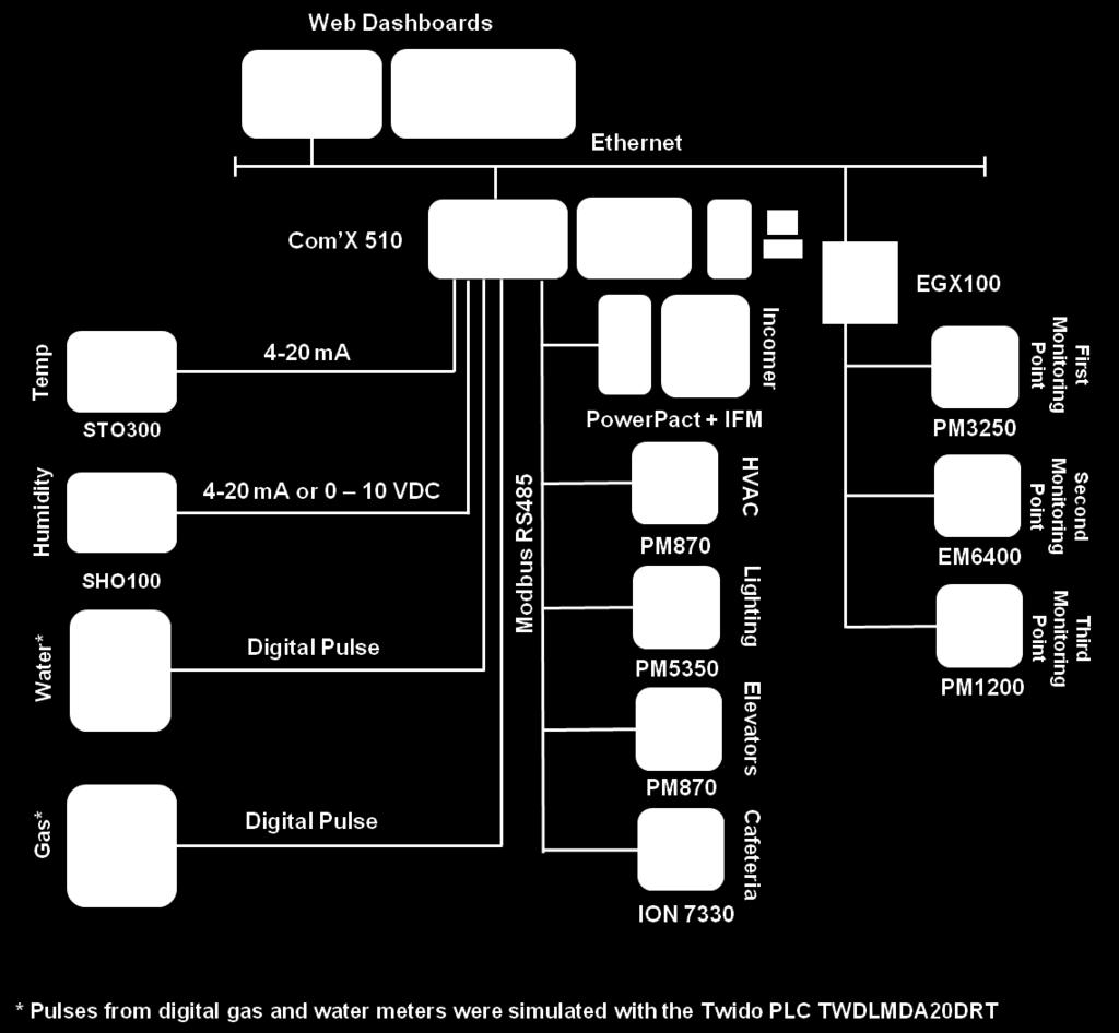
13 2 - Selection 2. Selection This TVD network architecture describes the network architecture for a switched mode connection with Com'X 510 and EGX100 gateways connected to the Ethernet network via an upstream switch. The EGX100 was chosen as a passthrough gateway for this solution because it allows remote access to connected devices. This architecture is appropriate for customers who: cannot connect to a hosted energy monitoring service for network isolation reasons. need a entry-level option for energy monitoring, without the high costs of software licenses, specialized hardware (such as server computers), support, and training Selected Architecture WAGES devices are connected both locally on the Com'X 510 inputs and serial port and remotely through the EGX100 serial port. The Com'X510 communicates with the EGX100 gateway through Ethernet. Energy consumption information can then be viewed for all devices in a web browser with the Com'X 510 Monitoring features and/or in an external application using the Publication feature. The devices for the selected architecture are: Electrical Modbus meters EM6400 ION 7330 PM3250, PM800 Series, PM5350, PM1200 Circuit breakers Powerpact A Pulse devices Gateway PowerLogic EGX 100 Ethernet Gateway 0-10V or 4-20mA devices SHO 100 Humidity Sensor STO 300 Temperature sensor This system is monitoring a single-phase 110 V AC voltage source (see Design for an electrical power diagram). The drawing below describes the network architecture: 13

14 2 - Selection 14

15 3 - Design and Validation 3. Design and Validation Your actual performance will vary, depending on environment, duty cycle, load type, and other factors Network Architecture The network architecture supports a switched mode connection with Com'X 510 and EGX100 gateways connected to the Ethernet network via an upstream switch. Three of the meters (PM3250, EM1200 and EM6400) are serially connected to the EGX100 and the rest of the meters are serially connected to the Com'X 510. Pulse meters and sensors are connected to the Com'X 510 digital and analog inputs. Below is the lab panel layout for the architecture: 15
16 3 - Design and Validation A TWIDO programmable logic controller was configured with TwidoSuite software v2.20 to generate two continuous pulse outputs at an interval of 100ms. These pulses are used as inputs to a water or gas custom pulse devices. These devices are based on custom models in the Com'X 510 Custom Library and are used to simulate water and gas flow rates. Com'X 510 product testing confirms that these types of meters are supported by Com'X Verification Results Commissioning the Com'X 510 for this architecture was completed in 23 minutes and 12 seconds, and includes the following configuration steps: 1. Upgrade firmware over USB (to v1.0.10). 2. Log in to the Com'X. 3. Verify the firmware is installed. 4. Set up publication. 5. Set up date/time. 6. Set up logging interval. 7. Configure Site information. 8. Add all devices (8) 9. Turn on publishing. 10. Turn on data logging. The serial devices were added using the Device Discovery feature. Custom models were created for the gas and water meters and humidity and temperature sensors, and this is included in the commissioning time Validation Results The Com'X 510 has built-in web pages for viewing real-time data and data stored on the box. The Monitoring tab provides real-time and historical chart views for devices through the gateway, and the Measurements Table provides views for equipment connected downstream. You can also refer to published data logs for each device for further data analysis. See Operation for details on using Com'X 510 energy monitoring features. 16

17 3 - Design and Validation The Year over Year Energy dashboard allows you to view total usage for each month: You can then view detailed monthly usage with Historical Trending, which displays all data points logged within the selected date range. For each topic, you can view up to four devices on the same graph. Below displays the value for each logging interval for the month of July: 17

18 3 - Design and Validation You can also view the current status of your system to look for unexpected usage, such as high after-hours energy usage. Real Time Data allows you to view detailed information for a single device or a summary of multiple devices: Single Device View for PM3250 Summary Device View: Power for PM3250 and PM870s 18
19 4 - Configuration & Implementation 4. Configuration and Implementation Refer to the documentation for each device in the selected architecture for complete instructions and safety information (see 8.2 Reference documents). Below are the configuration steps for the selected architecture. Processes may vary based on device substitutions Wiring Below is the 2-wire RS485 wiring diagram for connecting serial devices to the Com'X 510 and EGX100. Note that the selected device labels use a variety of symbols for RS485 wiring, and this drawing highlights examples of these differences Gateways Below is the wiring diagram for the EGX100 serial port and power supply. Refer to the EGX100 Installation Guide for complete instructions (see 8.2 Reference documents). 19
20 4 - Configuration & Implementation Micrologic and Powerpact Breakers Powerpact Wiring Diagram to Com X510 through the IFM: Analog Sensors SHO100 humidity sensor wiring diagram to the Com X510 in 0 10 V configuration: 20
21 4 - Configuration & Implementation SHO100 humidity sensor wiring diagram to the Com X510 in 4 20 ma configuration: STO300 Temperature Sensors 4 20 ma Wiring Diagram Pulse Devices TWD LMDA 20RT modular controller base was used to generate digital pulses, simulating digital gas and water meter inputs. Refer to the installation guide for your specific pulse meter(s) for wiring instructions (see 8.2 Reference documents). 21
22 4.2. Com'X 510 and EGX100 Serial Port Configuration 4 - Configuration & Implementation Serial communication settings for all devices on the serial bus must be the same and match the gateway settings. For example, values for EGX100 and Com'X510 for this TVDA are: Physical interface: RS485 2-Wire Number of stop bits: 1 Baud rate: Parity: None Response Timeout: 200 ms for EGX 100 and 1000 ms for Com'X Communication Settings for Serial Devices Serial communication settings for all devices on the serial bus must be the same and match the gateway settings. Values for this TVDA are: Baud rate: Parity: None Configuring the EM6400 You can use the meter display to configure Baud rate and parity for the EM Configuring the ION7330 Serial communications are available on COM1, and COM2. To enable communications through the meter serial ports, configure the applicable communications module. The Protocol, Tran delay, Baud rate, and unit ID setup registers must properly match your system and can be set through the meter front panel or ION software Configuring the PM1200 You can use the meter display to configure Baud rate and parity for the PM Configuring Micrologic and Powerpact Breakers You can communicate with a Micrologic or Powerpact circuit breaker through the IFM communication module. Use the two coding wheels on IFM front panel to set the Modbus address. The IFM module automatically detects the Baud rate and parity of the connected breaker when it is connected to the Modbus serial port Device Setup in the Com'X 510 To view energy consumption data on the Com'X 510, devices must be added to the Com'X 510 hierarchy and configured for logging. 22
23 4 - Configuration & Implementation Adding Devices To add remote and local serial devices and digital inputs in the Com'X 510 Device Settings: Use Device Discovery to discover the devices that are locally connected to the Modbus serial port and the downstream EGX100. Create or import the provided custom models for pulse meters. Add an input to the Com'X 510 under Digital and Analog Inputs. 23

24 4 - Configuration & Implementation After the devices are added in the Com'X 510, the Device Settings tab displays the hierarchy: Configuring Devices for Logging Each device logs certain measurements by default. You can customize the measurements to be logged and published for each device from Device Settings. Then, you can start data logging in the Commissioning main tab. The Com'X 510 User Manual contains a quick start guide for setting up data logging (see 8.2 Reference documents) Publishing.csv Data Logs For devices that are not viewable in the Monitoring tab, you may want to publish data logs for analysis outside the Com'X 510. You can set up the device log publication type (.csv) and frequency in Settings > General Settings > Publication. Then, start publication from the Commissioning main tab. 24
25 5 Operation 5. Operation The Com'X 510 provides views of real-time data along with historical data log trends and dashboards. After the devices are configured for logging, you can view data on the Monitoring and/or Measurements Table tab. Alternatively, you can view data logs for all devices in the published.csv files. NOTE: Power outages or device reboot may cause small gaps in data Viewing Data for Serial or Ethernet Devices For most devices connected to the Com'X 510 or EGX100 serial port, the Monitoring tab displays: Real Time Data for single or multiple devices. Energy Dashboards for comparing usage on a device time over time. Historical Trending for comparing usage on multiple devices for a topic or multiple topics for a single device. See the Com'X 510 User Manual for a list of devices that are not viewable in the Monitoring tab (see 8.2 Reference documents) Viewing Data for Devices through Digital or Analog Inputs Data from devices on the Com'X 510 digital and analog inputs are not available in the Monitoring tab. To view real time data for these devices, click the Measurements Table main tab, then scroll to the device. You can also refer to the published.csv data logs for historical data. 25
26 6 Maintenance 6. Maintenance 6.1. Com'X 510 Maintenance Update the Com'X firmware to the latest version as it becomes available, and clear browser cache after each firmware upgrade. You can find the latest firmware version in the Shopping Kiosk, the Solutions Expert Community, or the Com'X range page at Always back up the configuration before upgrading the Com'X 510 or after making any changes to the configuration Device Maintenance See the documentation for each connected WAGES device for maintenance related to the device's hardware or firmware (8.2 Reference documents). If you need to replace a connected device, you can also replace it within the Com'X 510 device tree view with the Replace Device feature. This allows you to update hardware with the same or similar device type while maintaining continuity in data reporting. Before replacing or removing a device, you must stop data logging and publishing in the Commissioning tab. After replacement, restart data logging and publishing. 26
27 7 - Conclusion 7. Conclusion This tested, validated, and documented architecture allows you to deploy the Com'X 510 energy server as an alternative to an energy monitoring software solution for small to medium buildings, including: Small schools, clinics, shops, retail convenience or chain stores Group housing, apartment blocks and high-end residential Small to medium hotels Colleges General offices and public buildings These instructions describe how to implement an architecture that supports devices connected to the Com X 510 inputs and serial port as well as Ethernet remote connections through the EGX100. Logged and real-time data can be viewed through Com'X 510 web pages and published data logs, providing a timely and detailed view of energy consumption for a facility, all at a lower cost to the end customer. 27
28 8 - Appendix 8. Appendix 8.1. Bill of material and software Description The following table summarizes all of the selected hardware. As noted in the Introduction, some of these devices can be substituted for devices with similar functionality: Reference Firmware or software version Function Com'X 510 EBX Energy server used for energy monitoring EGX100 Modbus Gateway EGX100SD Passthrough gateway for providing access to remote devices EM6400 EM6400IE DM 1.0RS Modbus electrical meter ION 7330 S7330A0B0B0E0A0A N/A Modbus electrical meter PM3250 METSEPM3250 v Modbus electrical meter PM870 PM870 v OS Modbus electrical meter PM5350 METSEPM5350 v3.0.4 OS Modbus electrical meter PM1200 METSEPM Modbus electrical meter. Firmware is not upgradable. PowerPact A HDL36030U54XEH V2.2.7 Circuit breaker IFM TRV00210 v1.1.1 Modbus interface module for communicating with PowerPact circuit breaker SHO 100 SHO100 N/A Humidity sensor STO 300 STO300 N/A Temperature sensor Web browser PC or mobile device Windows XP, Vista, or Windows 7 Allows viewing of logged and real time data for energy monitoring 8.2. Reference documents The following table is a list of documents you might want to refer to when more details are needed. They are available at or in the Schneider Electric Shopping Kiosk. Enter the document reference in the search box. Document title Reference Com'X 200, 210, 510 Instruction Sheet Com'X 510 User Manual Com'X 200 Metering and Data Acquisition System Installation Guide DOCA0098EN DOCA0035EN PowerLogic Ethernet Gateway EGX100 Installation Guide PowerLogic Ethernet Gateway EGX100 User Guide
29 8 - Appendix Document title Breaker Status Control Module (BSCM) with NSX Cord for PowerPact H-, J-, and L-Frame Circuit Breakers Instruction Bulletin SHO100 Outdoor Humidity Sensor Instructions STO 300 Temperature Sensor Instructions Twido PLC TWDLMDA20DRT Programmable Controllers Hardware Guide TwidoSuite V2.3 Programming Guide EM6400 Series Power Meter Quick Start Guide EM6400 User Manual Reference S1A FL FL K01000 CTD7302 NHA12535 ION 7330 Installation Guide ION 7330 User Manual PM3250/3255 Instruction Sheet PM3200 Series User Manual S1B46607 DOCA0006EN PM800 Series Power Meter Installation Guide PM800 Series Power Meter Quick Reference Guide PowerLogic Series 800 Power Meter PM810, PM820, PM850, & PM870 User Guide 3000DB PowerLogic PM5350 Installation Guide PowerLogic PM5350 User Manual PowerLogic PM1000 Series Quick Start Guide PowerLogic PM1000 Series Power Meters User Manual PLSED309038EN PLSED309039EN 8.3. Document Version Version Changes Author 1.0 Original version Katie Cullen 29
30 8 - Appendix 30
31 PowerLogic, Twido, and TwidoSuite are trademarks or registered trademarks of Schneider Electric. Other trademarks used herein are the property of their respective owners. Schneider Electric Industries SAS Head Office 35, rue Joseph Monier Rueil-Malmaison Cedex FRANCE Due to evolution of standards and equipment, characteristics indicated in texts and images in this document are binding only after confirmation by our departments. Version /2015
StruxureWare Power Monitoring Expert 8.0 Data Center Edition
 StruxureWare Power Monitoring Expert 8.0 Data Center Edition Breaker Performance Guide 7EN02-0367-01 06/2015 Safety information Important information Read these instructions carefully and look at the
Smart Mode Measurements
 Smart Mode Measurements Technical Reference for Maintenance PME 7.2.3 V1.0 Safety Information Important Information Read these instructions carefully before trying to install, configure, or operate this
Packaging User Guide for Temperature Control M221 Project Template
 Packaging EIO0000001762 04/2014 Packaging User Guide for Temperature Control M221 Project Template 04/2014 EIO0000001762.00 www.schneider-electric.com The information provided in this documentation contains
5521 Potentiometer Analog Input Module
 55 Potentiometer Analog Input Installation, Operation and Maintenance Setup Manual 5/9/0 Safety Information The information provided in this documentation contains general descriptions and/or technical
SoMachine Scan for Buttons Linked to ZBRN Modules Harmony ZBRN Library Guide
 SoMachine EIO0000001868 11/2016 SoMachine Scan for Buttons Linked to ZBRN Modules Harmony ZBRN Library Guide 11/2016 EIO0000001868.04 www.schneider-electric.com The information provided in this documentation
How Can I. Integrate a Third-Party Modbus Device with PowerSCADA Expert? System Technical Note PowerSCADA Expert V1.0
 How Can I Integrate a Third-Party Modbus Device with PowerSCADA Expert? System Technical Note PowerSCADA Expert V1.0 Safety Information Important Information Read these instructions carefully before trying
Galaxy Shore Connection 500 kva. Operation 04/
 Galaxy 7000 Shore Connection 500 kva Operation 04/2016 www.schneider-electric.com Legal Information The Schneider Electric brand and any registered trademarks of Schneider Electric Industries SAS referred
SCADAPack E Idec PLC Interface Manual
 SCADAPack E Idec PLC Interface Manual 2 SCADAPack E Idec PLC Interface Manual Table of Contents Part I Idec PLC Interface 3 1 Technical... Support 3 2 Safety... Information 4 3 Preface... 6 4 Overview...
Acti 9 Communication System
 Acti 9 Communication System Diagnostics User Manual 05/2012 DOCA0042EN-00 www.schneider-electric.com This document contains general descriptions and/or general technical specifications of the products
Generator Performance Guide 7EN /2015
 Generator Performance Guide 7EN02-0368-00 05/2015 Safety information Important information Read these instructions carefully and look at the equipment to become familiar with the device before trying
SCADAPack E Target 5 DF1 PLC Interface
 SCADAPack E Target 5 DF1 PLC Interface 2 Table of Contents Part I 3 1 Technical... Support 3 2 Safety... Information 4 3 Overview... 7 4 I/O Device... Interface 7 4.1 Input Devices... 9 4.2 Output Devices...
StruxureWare. Power Monitoring Expert 8.2 Hierarchy Manager Help Topics 7EN /2017
 StruxureWare Power Monitoring Expert 8.2 Hierarchy Manager Help Topics 7EN52-0413-00 03/2017 Legal Information The Schneider Electric brand and any registered trademarks of Schneider Electric Industries
5504 Thermocouple Analog Input Module
 550 Thermocouple Analog Input Installation, Operation and Maintenance Setup Manual 5/9/0 Safety Information The information provided in this documentation contains general descriptions and/or technical
Change Report Colors and Logo
 How to Change Report Colors and Logo Report Developer Kit V1.0 Safety Information Important Information Read these instructions carefully before trying to install, configure, or operate this software.
PowerLogic ION7550 RTU option
 70052-0213-02 PRODUCT OPTION 01/2011 PowerLogic ION7550 RTU option The PowerLogic ION7550 Remote Terminal Unit (RTU) option is designed for data acquisition from WAGES (water, air, gas, electricity, steam)
MultiTech Router Commissioning for Com X 200/210/510
 Knowledge Base 7EN42-0166 05/2017 MultiTech Router Commissioning for Com X 200/210/510 This document describes installation recommendations and how to commission a MultiTech rcell Series router for use
SCADAPack E ISaGRAF Quick Start Guide
 SCADAPack E ISaGRAF Quick Start Guide 2 SCADAPack E ISaGRAF Quick Start Guide Table of Contents Part I ISaGRAF 3 Quick Start Guide 3 1 Technical... Support 3 2 Safety... Information 4 3 Preface... 6 4
How Can I. Integrate a Third-Party DNP3 Device? System Technical Note PowerSCADA Expert V1.0
 How Can I Integrate a Third-Party DNP3 Device? System Technical Note PowerSCADA Expert V1.0 Safety Information Important Information Read these instructions carefully before trying to install, configure,
PowerLogic High Density Metering System 1-Meter Enclosure
 PowerLogic High Density Metering System 1-Meter Enclosure Installation Guide 63230-508-211A1 Safety information PowerLogic High Density Metering System 1-Meter Enclosure Important information Read these
Communication Interface
 Communication Interface Com'X 200/Com'X 210/Com'X 510 Technical data sheet Communications & gateways Com'X 200 / 210 Energy data loggers Main functions 1. Measure 2. Connect 3. Save PB114855 Wireless Meter
LXM32. Explanation for detected error E 733F. Expert Support Machine Solution
 LXM32 Explanation for detected error E 733F Expert Support Machine Solution The information provided in this documentation contains general descriptions and/or technical characteristics of the performance
StruxureWare Power Monitoring Expert for Healthcare 7.2
 StruxureWare Power Monitoring Expert for Healthcare 7.2 Commissioning Guide 7EN42-0070-04 09/2013 Safety Information Read these instructions carefully and look at the equipment to become familiar with
Com X 210, Com X 510 Technical Datasheet
 Com X 210, Com X 510 Technical Datasheet A highly flexible plug-and-play Energy Server Com X 210 collects and stores WAGES consumptions and environmental parameters such as temperatures, humidity and CO
Ethernet Modbus X80 Gateway Device Type Manager
 Ethernet Modbus X80 Gateway Device Type Manager EIO0000001315 10/2012 Ethernet Modbus X80 Gateway Device Type Manager User Manual 10/2012 EIO0000001315.00 www.schneider-electric.com The information provided
StruxureWare Power Monitoring 7.0
 StruxureWare Power Monitoring 7.0 OPC Server Assistant 7EN02-0309-00 02/2012 Contents Safety information 5 Introduction 7 Scope 7 Optional OPC Server License 8 OPC Server Type 8 OPC Server Support 9 Creating/Updating
5401 and 5402 Digital I/O Modules
 50 and 50 Digital I/O Modules Installation, Operation and Maintenance Setup Manual 5/9/0 Safety Information The information provided in this documentation contains general descriptions and/or technical
Conext CL-60 Inverter Firmware Upgrade Process
 Conext CL-60 Inverter Firmware Upgrade Process http://solar.schneider-electric.com 976-0380-01-01/B August 2017 Application Note EXCLUSION FOR DOCUMENTATION UNLESS SPECIFICALLY AGREED TO IN WRITING, SELLER
5403 and 5404 Digital Input Modules
 503 and 50 Digital Input Modules Installation, Operation and Maintenance Setup Manual //07 Copyright 0-07 Schneider Electric Canada Inc. All rights reserved. 503 and 50 Digital Input Modules The information
Conext EasyConfig Tool
 Conext EasyConfig Tool Owner s Guide 975-0796-01-01 Revision A 05-2018 http://solar.schneider-electric.com Copyright 2018 Schneider Electric. All Rights Reserved. All trademarks are owned by Schneider
Gateways & Energy Servers
 Gateways & Energy Servers Partner Business Power Solutions GES James Jeanette Gateways Energy Servers EGX100 EGX300 COM X 200 Gateways EGX100 From a single building, to a multi-site enterprise, the EGX100
Momentum 170ENT11001/170ENT11002 Ethernet Communications Adapter User Guide
 Momentum 31004109 09/2017 Momentum 170ENT11001/170ENT11002 Ethernet Communications Adapter User Guide 09/2017 31004109.07 www.schneider-electric.com The information provided in this documentation contains
ACCESS 9340/9360 Meter Input/Output Module
 Installation Manual PMIM-IOMOD-0208 ACCESS 9340/9360 Meter Input/Output Module 9340-60-I/O2222 and 9340-60-I/O26 HAZARD CATEGORIES AND SPECIAL SYMBOLS Read these instructions carefully and look at the
Electrical network protection Sepam series 20 Sepam series 40 Quick start
 03146790FE+01+NP00000000 Electrical network protection Sepam series 20 Sepam series 40 Quick start PE50465 Storage Sepam may be stored in its original packaging in a closed sheltered location: b ambient
Symmetra PX 160. Maintenance Bypass Enclosure. Installation 05/
 Symmetra PX 160 Maintenance Bypass Enclosure Installation 05/2014 www.schneider-electric.com Legal Information The Schneider Electric brand and any registered trademarks of Schneider Electric Industries
PowerLogic TM Series E4800 Multi-Circuit Meters. Configuration Guide
 PowerLogic TM Series E4800 Multi-Circuit Meters Configuration Guide PowerLogic TM E4800 Series 930-112-01 02/2009 Hazard Categories and Special Symbols Read these instructions carefully and look at the
PowerLogic TM Series EM4800 Multi-Circuit Meters. Configuration Guide
 PowerLogic TM Series EM4800 Multi-Circuit Meters Configuration Guide PowerLogic TM EM4800 Series 930-112-01-B.00 01/2011 Hazard Categories and Special Symbols Read these instructions carefully and look
EIO /2011. Magelis HMISTO501. Zelio/Millenium Driver 07/2011 EIO
 EIO0000001026 07/2011 Magelis HMISTO501 Zelio/Millenium Driver 07/2011 EIO0000001026.00 www.schneider-electric.com 2 EIO0000001026 07/2011 Table of Contents Safety Information.............................
DOCA0069EN 10/2016. Ecoreach Online Help. Version /2016 DOCA0069EN-04.
 Ecoreach DOCA0069EN 10/2016 Ecoreach Online Help Version 2.2 10/2016 DOCA0069EN-04 www.schneider-electric.com The information provided in this documentation contains general descriptions and/or technical
SCADAPack E 5405 Digital Input Hardware Manual
 SCADAPack E 5405 Digital Input Hardware Manual 2 SCADAPack E 5405 Digital Input Hardware Manual Table of Contents Part I 5405 Digital Input Module 3 1 Technical... Support 3 2 Safety... Information 4 3
Communication Interface
 Communication Interface Com'X 200 Technical data sheet Communications Functions and characteristics PB112041 Ethernet GPRS data logger function The collects and stores wages consumptions (Water, Air, Gas,
The synergy of SCADA with energy control
 The synergy of SCADA with energy control StruxureWare PowerSCADA Expert Power monitoring and control software Oil and Gas Energy and Infrastructure Data Centres Uncompromising supervision for your critical
EcoStruxure Power Commission Installation Guide
 EcoStruxure Power Commission DOCA0134EN 03/2019 EcoStruxure Power Commission Installation Guide 03/2019 DOCA0134EN-04 www.schneider-electric.com The information provided in this documentation contains
PowerLogic communication devices. EGX100 Ethernet gateway EGX300 Integrated gateway-server. Technical data sheet
 PowerLogic communication devices EGX100 Ethernet gateway EGX300 Integrated gateway-server Technical data sheet PLSED309034EN.indd 1 Ethernet gateway PE86138 Function The EGX100 serves as an Ethernet gateway
Conext CL-60 EasyConfig Tool
 Conext CL-60 EasyConfig Tool Owner s Guide 975-0773-01-01 Revision B 08-2017 http://solar.schneider-electric.com Copyright 2017 Schneider Electric. All Rights Reserved. All trademarks are owned by Schneider
Com'X 510. User Manual DOCA0098EN-03 04/2016
 Com'X 510 User Manual DOCA0098EN-03 04/2016 Com'X 510 User Manual Safety Information Safety Information Important Information Read these instructions carefully and look at the equipment to become familiar
Com'X 510. User Manual DOCA0098EN-02 12/2015
 Com'X 510 User Manual DOCA0098EN-02 12/2015 Safety Information Safety Information Important Information Read these instructions carefully and look at the equipment to become familiar with the device before
Symmetra MW kw 380/400/480 V Operation. UPS System with External Bypass 01/
 Symmetra MW 800 1600 kw 380/400/480 V Operation UPS System with External Bypass 01/2017 www.schneider-electric.com Legal Information The Schneider Electric brand and any registered trademarks of Schneider
Gateways & Energy Servers
 Gateways & Energy Servers Partner Business Power Solutions GES James Jeanette Joelle Key Gateways Energy Servers EGX100 EGX300 CONN X 200 Gateways and Energy Servers Contacts For any questions concerning
PowerLogic ION Setup 3.0
 PowerLogic ION Setup 3.0 Meter configuration software User guide 7EN02-0312-00 03/2012 Contents Safety information 7 Chapter 1: Safety precautions 9 Chapter 2: Introduction 11 ION Setup features 12 Your
PowerLogic ION7300 Series
 PowerLogic ION7300 Series Power and Energy Meter Advanced Field Retrofit Instructions August 2006 Danger This symbol indicates the presence of dangerous voltage within and outside the product enclosure
5502 Differential Analog Input Module
 550 Differential Analog Input Installation, Operation and Maintenance Setup Manual //07 Copyright 0-07 Schneider Electric Canada Inc. All rights reserved. 550 Differential Analog Input The information
SCADAPack E ISaGRAF 3 I/O Connection Reference
 SCADAPack E ISaGRAF 3 I/O Connection Reference 2 SCADAPack E ISaGRAF 3 I/O Connection Reference Table of Contents Part I ISaGRAF 3 I/O Connection 4 1 Technical... Support 4 2 Safety... Information 5 3
Installation and Operation Back-UPS BR1000G-IN / BR1500G-IN
 Installation and Operation Back-UPS BR1000G-IN / BR1500G-IN Important Safety Information Read the instructions carefully to become familiar with the equipment before trying to install, operate, service
Com X 510 Energy Server User manual DOCA0098EN-07 07/2017
 Com X 510 Energy Server User manual DOCA0098EN-07 07/2017 www.schneider-electric.com Legal Information The Schneider Electric brand and any registered trademarks of Schneider Electric Industries SAS referred
Square D Clipsal Pascal Automation Controller
 Square D Clipsal Pascal Automation Controller SLC5500PACA For Use with Wired C-Bus Networks Instruction Bulletin Retain for future use. Square D Clipsal Pascal Automation Controller 63249-420-258A2 Instruction
CEM M-RS485 INSTRUCTION MANUAL (M014B A)
") Communications interface CEM M-RS485 INSTRUCTION MANUAL (M014B01-03-14A) 2 SAFETY PRECAUTIONS Follow the warnings described in this manual with the symbols shown below. DANGER Warns of a risk, which could
Communications interface CEM M-RS485 INSTRUCTION MANUAL (M014B01-03-14A) 2 SAFETY PRECAUTIONS Follow the warnings described in this manual with the symbols shown below. DANGER Warns of a risk, which could
XPSMCMx Fieldbus Expansion Modules Instruction Sheet (Original Language)
") XPSMCMx Fieldbus Expansion Modules EAV8283001 12/2014 XPSMCMx Fieldbus Expansion Modules Instruction Sheet (Original Language) 12/2014 EAV8283001.00 www.schneider-electric.com The information provided
XPSMCMx Fieldbus Expansion Modules EAV8283001 12/2014 XPSMCMx Fieldbus Expansion Modules Instruction Sheet (Original Language) 12/2014 EAV8283001.00 www.schneider-electric.com The information provided
Security Quick Start Guide
 2 Table of Contents Part I 4 1 Technical... Support 4 2 Safety... Information 5 3 Introduction... 7 4 Security... Overview 8 5 How to... Configure DNP3 Secure Authentication 11 5.1 Check RTU Firm... w
DOCA0069EN 09/2014. Ecoreach Online Help. Version /2014 DOCA0069EN-00.
 Ecoreach DOCA0069EN 09/2014 Ecoreach Online Help Version 1.0 09/2014 DOCA0069EN-00 www.schneider-electric.com The information provided in this documentation contains general descriptions and/or technical
Additional Device Support in PowerLogic ION Enterprise 6.0
 70072-0191-00 TECHNICAL 06/2009 Additional Device Support in PowerLogic ION Enterprise 6.0 This document outlines support in ION Enterprise 6.0 for devices that are not based on ION architecture. In This
Source-Transfer Application Guide
 S&C Model 6802 Automatic Switch Control Source-Transfer Application Guide Table of Contents Section Page Section Page Introduction Qualified Persons.... 2 Read this Instruction Sheet.... 2 Retain this
BCM ULP Breaker Communication Module
 DOCA0152EN-00 BCM ULP Breaker Communication Module Firmware Version 4.1.9 Release Note 05/2018 The information provided in this documentation contains general descriptions and/or technical characteristics
Power Manager for SmartStruxure Solution
 Power Manager for SmartStruxure Solution Design Guide 7EN02-0355-00 03/2015 Power Manager Design Guide Safety precautions Safety information Important information Read these instructions carefully and
StruxureWare Power Monitoring Expert
 StruxureWare Power Monitoring Expert Hierarchy Configuration Guide 7EN42-0101-00 02/2014 Hierarchy Configuration Utility Guide Safety information Safety information Important information Read these instructions
Twido Programmable Controllers Discrete I/O Modules
 Twido Programmable Controllers Discrete I/O Modules Hardware Guide 03/2007 www.telemecanique.com 2 Table of Contents Safety Information....................................5 About the Book.......................................9
Technical Specificaions. kwh Energy Meter
 Technical Specificaions of kwh Energy Meter (SPK301) Class 1.0S Sai PowerrZerve 29/3B, Rajalakshmi Nagar, 1 st Main Road, Velachery Bye Pass, Chennai 600 042. Website :www.spowerz.com Email : info@spowerz.com
Altivar 61/71 Adjustable Speed Drives Heatsink Fan Kits VZ3V1212 and VZ3V1216
 Altivar 61/71 Adjustable Speed Drives Heatsink Fan Kits VZ3V1212 and VZ3V1216 Instruction Bulletin 30072-452-48 Retain for future use. 30072-452-48 Altivar 61/71 Heatsink Fan Kits VZ3V1212 and VZ3V1216
Clipsal Bus Couplers. Two Channel (SLC5102BCLEDL) and Four Channel (SLC5104BCL) for Use with C-Bus Wired Systems
 and Four Channel (SLC5104BCL) for Use with C-Bus Wired Systems") Clipsal Bus Couplers Two Channel (SLC5102BCLEDL) and Four Channel (SLC5104BCL) for Use with C-Bus Wired Systems Instruction Bulletin Retain for future use. Clipsal Bus Couplers 63249-420-236A2 Instruction
Clipsal Bus Couplers Two Channel (SLC5102BCLEDL) and Four Channel (SLC5104BCL) for Use with C-Bus Wired Systems Instruction Bulletin Retain for future use. Clipsal Bus Couplers 63249-420-236A2 Instruction
SCADAPack E Koyo DirectNET PLC Interface Manual
 SCADAPack E Koyo DirectNET PLC Interface Manual 2 SCADAPack E Koyo DirectNET PLC Interface Manual Table of Contents Part I Koyo DirectNET PLC Interface 3 1 Technical... Support 3 2 Safety... Information
TSXCUSBMBP USB Modbus Plus Communications Adapter User Manual eng
 TSXCUSBMBP USB Modbus Plus Communications Adapter User Manual 35011984 eng 2 Table of Contents Safety Information.................................... 5 About the Book.......................................7
User Manual Revision English
 Document code: MN67562_ENG Revision 1.005 Page 1 of 14 User Manual Revision 1.005 English PROFIBUS Slave / Modbus Slave - Converter (Order Code: HD67562) for Website information: www.adfweb.com?product=hd67562
Technical Specifications. Dual Source kwh Energy Meter
 Technical Specifications of Dual Source kwh Energy Meter (SPKG300) Class 0.5S Sai PowerrZerve 29/3B, Rajalakshmi Nagar, 1 st Main Road, Velachery Bye Pass, Chennai 600 042. Website :www.spowerz.com Email
ULP System ULP (Universal Logic Plug) System User Guide
 System User Guide") ULP System 0602IB1503-00 10/2015 ULP System ULP (Universal Logic Plug) System User Guide 10/2015 0602IB1503-00 www.schneider-electric.com The information provided in this documentation contains general
ULP System 0602IB1503-00 10/2015 ULP System ULP (Universal Logic Plug) System User Guide 10/2015 0602IB1503-00 www.schneider-electric.com The information provided in this documentation contains general
StruxureWare Power Monitoring Expert and StruxureWare Building Operation Integration Design Guide 7EN /2015
 StruxureWare Power Monitoring Expert and StruxureWare Building Operation Integration Design Guide 7EN42-0112-01 07/2015 Safety precautions Safety information Important information Read these instructions
5910 Ethernet Gateway Module
 Hardware Manual 2/24/2017 Copyright 2014-2017 Schneider Electric Canada Inc. All rights reserved. 5910 Ethernet Gateway Module The information provided in this documentation contains general descriptions
Application Note on Modifying Disconnect Settings for Xantrex GT Series Single Phase Inverters and Conext TX Series Inverters
 Application Note on Modifying Disconnect Settings for Xantrex GT Series Single Phase Inverters and Conext TX Series Inverters 976-0312-01-01 Revision A DANGER RISK OF FIRE, ELECTRIC SHOCK, EXPLOSION, AND
Installing firmware update with Spanish language support on PM5350 using DLF v2
 Installing firmware update with Spanish language support on PM5350 using DLF3000 3.3 v2 This tutorial will demonstrate how to update the firmware of PM5350 meter using DLF3000 software and serial communication.
Application Note: Using Modbus With the Conext CL Series. Important Safety Instructions
 : Using Modbus With the Conext CL Series 976-0317-01-01 Rev A Important Safety Instructions READ AND SAVE THESE INSTRUCTIONS - DO NOT DISCARD This document contains important safety instructions that must
How can I. Connect PlantStruxure to FOUNDATION Fieldbus? Design Your architecture. System Technical Note Optimized functional unit
 How can I Connect PlantStruxure to FOUNDATION Fieldbus? System Technical Note Optimized functional unit Design Your architecture Important Information Notice People responsible for the application, implementation
Multi-Loader. User manual 06/ BBV48778
 Multi-Loader User manual 06/2009 BBV48778 www.schneider-electric.com Contents Important information 4 Before you begin 5 Documentation structure 6 Setup procedure 7 Introduction 8 Receipt of the Multi-Loader
Unity Loader A SoCollaborative Software User Manual
 Unity Loader 33003805 02/2017 Unity Loader A SoCollaborative Software User Manual 02/2017 33003805.11 www.schneider-electric.com The information provided in this documentation contains general descriptions
User Manual Revision English
 Document code: MN67152_ENG Revision 1.002 Page 1 of 17 User Manual Revision 1.002 English HD67152-A1 DeviceNet Master / Modbus TCP Slave - Converter (Order Code: HD67152-A1 HD67152-B2) for Website information:
Configuration. S&C Scada-Mate Switching System Outdoor Distribution (14.4 kv through 34.5 kv)
") S&C Scada-Mate Switching System Outdoor Distribution (14.4 kv through 34.5 kv) Communication Processor Module For Communication and Control Unit Configuration Table of Contents Section Page Section Page
S&C Scada-Mate Switching System Outdoor Distribution (14.4 kv through 34.5 kv) Communication Processor Module For Communication and Control Unit Configuration Table of Contents Section Page Section Page
SCADAPack E 5505 RTD Input Hardware Manual
 SCADAPack E 5505 RTD Input Hardware Manual 2 SCADAPack E 5505 RTD Input Hardware Manual Table of Contents Part I 5505 RTD Input Module 3 1 Technical... Support 3 2 Safety... Information 4 3 Overview...
SoMachine. M238 High Speed Counting Functions High_Speed_Counter_M238.project Example Guide. 04/2012 Basic. Intermediate Expert
 SoMachine M238 High Speed Counting Functions High_Speed_Counter_M238.project Example Guide 04/2012 Basic Intermediate Expert EIO0000000905.00 www.schneider-electric.com The information provided in this
Galaxy VM. System Bypass Cabinet 640 kva Installation GVMSBC640KHEL 06/2016.
 Galaxy VM System Bypass Cabinet 640 kva Installation GVMSBC640KHEL 06/2016 www.schneider-electric.com Legal Information The Schneider Electric brand and any registered trademarks of Schneider Electric
Multilin EPM 4600 Metering Solution
 GE Digital Energy Multilin EPM 4600 Metering Solution Multi-feed Power and Energy Metering Solution Quick Start Guide GE publication code: 1601-0297-A2 (GEK-119590A) 1601-0297-A2 Copyright 2014 GE Multilin
CEM-C6 INSTRUCTION MANUAL (M187B B)
") Multifunctional Energy Meter INSTRUCTION MANUAL (M187B01-03-18B) 2 SAFETY PRECAUTIONS Follow the warnings described in this manual with the symbols shown below. DANGER Warns of a risk, which could result
Multifunctional Energy Meter INSTRUCTION MANUAL (M187B01-03-18B) 2 SAFETY PRECAUTIONS Follow the warnings described in this manual with the symbols shown below. DANGER Warns of a risk, which could result
Event Notification Module
 Event Notification Module Installation Guide Version 8.2 4/2014 2014 Schneider Electric. All Rights Reserved. SAFETY INFORMATION Read these instructions carefully and look at the equipment to become familiar
PS/IO Circuit Board Retrofit
 S&C 6800 Series Automatic Switch Controls PS/IO Circuit Board Retrofit Table of Contents Section Page Introduction Qualified Persons.... 2 Read this Instruction Sheet.... 2 Retain this Instruction Sheet....
Enerlin'X IFE Switchboard Server IFE/EIFE Ethernet Interface
 DOCA0147EN-01 Enerlin'X IFE Switchboard Server IFE/EIFE Ethernet Interface Firmware Version 003.007.024 Release Note 05/2018 The information provided in this documentation contains general descriptions
Power Manager for SmartStruxure Solution
 Power Manager for SmartStruxure Solution Integration Manual 7EN02-0354-00 04/2015 Safety precautions Power Manager for SmartStruxure Solution - Integration Manual Safety information Important information
PTZ Control VMC Joystick
 Installation and Configuration English PTZ Control VMC Joystick Rev. 1.0.0 / 2010-07-20 Information about Copyright, Trademarks, Design Patents 2010 Dallmeier electronic The reproduction, distribution
PowerMonitor 5000 Unit Catalog Number Upgrade
 Installation Instructions PowerMonitor 5000 Unit Catalog Number Upgrade Catalog Numbers 1426-MxE-xxx Topic Page Upgrade the Device Catalog Number with the ControlFLASH Utility 3 Determine Communication
StruxureWare Power Monitoring Expert 8.0
 StruxureWare Power Monitoring Expert 8.0 Installation Guide 7EN02-0358-00 05/2015 StruxureWare Power Monitoring Expert Installation Guide Safety information Safety information Important information Read
PM Series Power Meter
 PM Series Power Meter Quick Setup Guide - PMC-1000, PMC- 1001, PMM-1000, PMB-1960 Safety Information DANGER! HAZARD OF ELECTRIC SHOCK, EXPLOSION, OR ARC FLASH Follow safe electrical work practices. See
Installation Guide SMT 2200/3000 VA Input/Output Hardwire Kit
 Installation Guide SMT 2200/3000 VA Input/Output Hardwire Kit Important Safety Messages SAVE THESE INSTRUCTIONS - This section contains important instructions that should be followed during installation
Temposonics Magnetostrictive Linear Position Sensors
 Temposonics Magnetostrictive Linear Position Sensors TempoLink Smart Assistant I AM V THE NEW GENERATION Table of contents 1. Introduction...3 2. Safety instructions...4 2.1 Intended use...4 2.2 Foreseeable
BCM2 Series Branch Circuit Monitors Quick Setup Guide
 BCM2 Series Branch Circuit Monitors Quick Setup Guide Safety Information DANGER! HAZARD OF ELECTRIC SHOCK, EXPLOSION, OR ARC FLASH Follow safe electrical work practices. See NFPA 70E in the USA, or applicable
Installing and Configuring Rialto Analytic Appliances
 Installing and Configuring Rialto Analytic Appliances Important Safety Information This manual provides installation and operation information and precautions for the use of this camera. Incorrect installation