MIP480 Mobile Impact Printer
|
|
|
- Bonnie Morgan
- 6 years ago
- Views:
Transcription


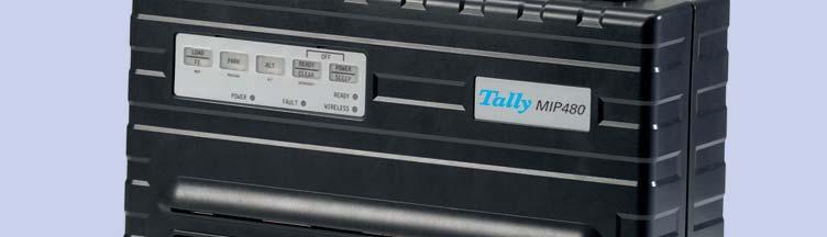


1 User Guide MIP480 Mobile Impact Printer
2 FCC Compliance Statement This device complies with Part 15 of the FCC Rules. Operation is subject to the following two conditions: (1) This device may not cause harmful interference, and (2) This device must accept any interference received, including interference that may cause undesired operation. Canadian Compliance Statement This digital apparatus is in conformity with standard NMB-003 of Canada. Cet appareil numérique est conforme à la norme NMB-003 du Canada. Radio and Television Interference When installed at a certain location, the machine may cause interference with radio and television reception. If you notice flickering or distorted images or noises on your audio-visual units, your machine maybe causing radio interference. Switch it off, and if the interference disappears, the machine is the cause of radio interference. Perform the following procedure until the interference is corrected. Move the machine and the TV and/or radio away from each other. Reposition or reorient the machine and TV and/or radio. Unplug the machine, TV and/or radio, and re-plug them into outlets that operate on different circuits. Reorient the TV and/or radio antennas and cables until the interference stops. For an out-door antenna, ask your local electrician for support. Use coaxial cable antennas. FCC warning: Changes or modifications not expressly approved by the party responsible for compliance could void the user s authority to operate the equipment. Notes 1. The use of a non-shielded parallel interface cable with the referenced device is prohibited. The length of the parallel interface cable must be 3 meters (10 feet) or less. The length of the serial interface cable must be 600 meters (1970 feet) or less. 2. The length of the power cord must be 3 meters (10 feet) or less. Notice to Canadian Users This digital apparatus does not exceed the class B limits for radio noise emissions from digital apparatus set out in the Radio Interference Regulations of the Canadian Department of Communications. This equipment is in the 2nd class category (information equipment to be used in a residential area or an adjacent area thereto) and conforms to the standards set by the Voluntary Control Council for Interference by Information Technology Equipment aimed at preventing radio interference in such residential area. When used near a radio or TV receiver, it may become the cause of radio interference. Read the instructions for correct handling.
3 Table of Contents Introduction 1-1 Features 1-2 Options 1-2 Paper Handling 2-1 Getting to Know the Printer s Major Parts and the Control Panel 2-1 Operations of the Control Panel 2-4 Basic States of the Printer 2-4 Selecting Paper 2-7 Paper Specifications 2-7 Paper Size 2-7 Paper Thickness and Number of Copies 2-7 Overview of Paper Operations 2-8 Levers and keys used for Paper Handling 2-9 Adjusting for Paper Thickness 2-10 Using Continuous Forms 2-11 Positioning the Paper Stack 2-11 Loading Continuous Forms (Push Tractor) 2-12 Unloading Continuous Forms 2-14 Recovering from an Unexpected Unloading Operation 2-14 Automatic-Tear-Off Advancing 2-14 Manual Tear-Off Advancing 2-14 Using Single Sheets 2-16 Loading a Single Sheet of Paper 2-16 Ejecting Single Sheets 2-17 Feeding and Positioning Paper 2-18 Print Area Definition 2-18 Form Feed 2-19 Switching Paper Types 2-20 Switching from Continuous Forms to Single Sheets 2-20 Switching from Single Sheets to Continuous Forms 2-21 Tips on Paper Handling 2-21 General Tips 2-21 Multipart Forms 2-21 i
4 Table of Contents Printing 3-1 Using the Control Panel 3-1 Starting or Stopping Printing 3-2 Starting Printing 3-2 Stopping and Viewing Printing 3-2 Resuming Printing 3-2 Resuming from a Paper-Out 3-2 Removing Printed Pages 3-3 Removing Single Sheets 3-3 Sleep Mode 3-4 Entering Sleep Mode 3-4 Leaving Sleep Mode 3-4 Using Special Mode 4-1 Special Mode Functions 4-1 Entering Special Mode 4-2 Set-Up Mode Function 4-3 How Set-Up Works 4-3 Entering the Set-Up Mode 4-4 Overview of the Set-Up Mode 4-5 Options with Pre-determined Values 4-7 Options with Undetermined Values 4-8 Points to Remember 4-10 Macro Options and Values 4-11 INSTALL Options and Values 4-16 Safe Panel 4-18 Recalling Factory Settings 4-18 Exiting and Saving 4-19 Using the Diagnostic Functions 4-20 Print Configuration Function 4-20 Printing Test Function 4-22 Hex Dump Mode 4-23 Printing Alignment Adjustment 4-24 Top Adjustment Function 4-26 Setting of The First Dot Position on The Left Side Function 4-28 Changing Menu Access Options 4-30 MENU ACCESS Option and Values 4-30 Setting Setup Mode to Default Value (Standard) 4-31 Setting Setup Mode to Default Value (6820 Mode) 4-31 Set-Up Mode Quick Reference 4-32 ii
5 Table of Contents Maintenance 5-1 Cleaning 5-1 Cleaning and Vacuuming the Printer 5-1 Cleaning the Paper Bail Rollers 5-2 Cleaning the Print Head 5-3 Replacing the Ribbon Cartridge 5-4 Removing the Ribbon Cartridge 5-4 Installing the Ribbon 5-5 Replacing the Print Head 5-6 Trouble-Shooting 6-1 Solving problems 6-1 Print Quality Problems and Solutions 6-2 Paper Handling Problems and Solutions 6-3 Operating Problems and Solutions 6-4 Printer Failures 6-5 Diagnostic Functions 6-5 Checking Vertical Alignment 6-5 Supplies and Options A-1 Supplies A-1 Options A-1 Printer and Paper Specifications B-1 Printer Specifications B-1 Physical Specifications B-1 Functional Specifications B-3 Performance Specifications B-6 Paper Specifications B-7 Print Area B-7 Paper Thickness B-9 Command Sets C-1 Interface Information D-1 Removing the Connectivity Cover D-1 Serial Interface D-2 Serial Options D-3 Buffer Control D-4 iii
6 Table of Contents USB Interface (Universal Serial Bus) D-5 Features D-5 Bluetooth Wireless Interface D-6 IEEE B/G Wireless Interface (Option) D-6 Character Sets E-1 Common to IBM Proprinter Emulation and Epson-EP2 Emulation E-1 Code Page 437 E-2 Code Page 437 Greek E-2 Code Page 850 E-3 Code Page 851 E-3 Code Page 852 E-4 Code Page 853 E-4 Code Page 855 E-5 Code Page 857 E-5 Code Page 858 E-6 Code Page 860 E-6 Code Page 863 E-7 Code Page 864 E-7 Code Page 865 E-8 Code Page 866 E-8 Code Page 869 E-9 Code Page 920 E-9 Code Page 923 E-10 Code Page USSR GOST E-10 IBM Proprinter Emulation E-11 IBM Set 1 and 2 E-11 IBM Set 1 E-11 IBM Set 2 E-11 Epson-EP2 Emulation E-12 National Character Sets E-12 Common Characters E-12 National Characters E-13 iv

7 1 Introduction Congratulations on purchasing the Tally Mobile Impact Printer 480 (MIP480). This printer is an 80 column, 24 wire, serial dot matrix printer specifically designed as a robust output device for use in vehicular applications. This compact, versatile printer offers maximum compatibility with today s software packages and personal computers. The 24-wire print head provides crisp, clear printing of invoices and documents. This printer is also easy to install and use. Mobile Impact Printer
8 Introduction Features Key printer features and options are listed in the next two sections. Software compatibility. This printer operates with IBM Proprinter XL24E and Epson-EP2 emulations. Various character sets. For IBM Mode: IBM Set 1 and Set 2. For EPSON Mode: 15 National Character Sets. Multiple fonts. The printer has thirteen resident fonts: Draft, Roman, Sans Serif, Courier, Bold, Prestige, Script, Orator, Gothic, OCR-A, OCR-B, Sans Serif H and Roman T. Two scalable fonts Roman and Sans Serif. High-speed printing. At 10 cpi, print speed ranges from 400 cps for high-speed draft quality to 133 cps for letter quality. 64K bytes of input buffer. 64K bytes are available for storing input data and downloading custom fonts. Simple switching of paper types. The ability to park continuous forms to switch between continuous forms and single sheets. Two positions capability. The printer may be mounted vertically on a panel or seat back in a standard transportation vehicle, or horizontally on the passenger seat or other location. The push tractor feeds the continuous forms. Automatic tear-off advancing. With factory settings of the Set-Up mode, continuous forms perforations are automatically advanced up to the tear bar at the end of each job so that forms can be torn off. Auto viewing. Paper (continuous forms or single sheets) is automatically advanced at the end of each printing so that the last printed line can be read. Maintenance-free. The printer only requires periodic cleaning and changing of the ribbon cartridge. Options Printer configurations are available with: B Wireless Ethernet. 1-2
9 2 Paper Handling This chapter explains how your printer handles paper. Topics covered are: Getting to know the printer s major parts and the control panel Selecting paper Overview of paper operations Adjusting for paper thickness Using single sheets Using continuous forms Feeding and positioning paper Switching paper types Tips for paper handling are given at the end of this chapter. Check that section if you are using multipart forms, invoices, envelopes, or labels. Getting to Know the Printer s Major Parts and the Control Panel This section describes the major parts and controls of the printer and operations of the control panel. Take a moment to become familiar with the printer. 2-1
 5 Single Sheet Edge Guides (to adjust location of single sheets) 6 Easy Load Platforms 7 Tractor Doors (to hold and feed continuous forms) 8 Front/Bottom Control Panel")
10 Paper Handling Front View 1 Top Cover 2 Cut Sheet Edge 3 Power Supply Connector (to connect to the vehicle battery) 4 Control Panel (to load and feed paper, select print features, or change the printer s optional settings) 5 Single Sheet Edge Guides (to adjust location of single sheets) 6 Easy Load Platforms 7 Tractor Doors (to hold and feed continuous forms) 8 Front/Bottom Control Panel 2-2
 4 Paper Guides (to guide single sheets) 5")
 Vertical Position Bottom")
11 Paper Handling Front Rear Left Side View 1 Power Switch 2 Cover Latch (to secure top cover) 3 Forms Tractors (to hold and feed continuous forms) 4 Paper Guides (to guide single sheets) 5 Paper Exit Slot and Tear Edge 6 Top Cover Rear 7 Single Sheet Tray (Shown in down Position) Bottom View 8 Interface Connectors (or Wireless Adapters if installed) Vertical Position Bottom View 2-3
12 Paper Handling Operations of the Control Panel This section summarizes status indications and operations of the control panel in Normal mode. For details on Set-Up mode, see Chapter 4, Using Set-Up Mode. Normal mode operation includes everyday operations, such as paper handling, font selection, macro selection, and protocol selection. The first table lists basic states represented by the Ready and Fault indicators. The second table lists Normal mode operations and required user response. Operations are listed by functions. Basic States of the Printer Indicator Status Printer Status Ready On The printer is ready for printing or the printer is receiving or printing data. Blinking Off The printer is not ready and holds printing data. The printer is not ready and it does not hold printing data. Fault On The printer is out of paper. Blinking slowly Blinking fast The printer has detected an operational error: paper jam, interface error, carriage error, paper unloading error, etc. The printer detected diagnostic errors at power-up. 2-4
13 Paper Handling Operation Required Conditions *1 Required Action Ready Printing *2 Fault Load continuous forms paper Not printing On Press FF/LOAD. Load single sheet paper Not printing On Paper is automatically detected and advanced (autoloading) when it is first inserted. In this mode, if the FF key is pushed, the inserted sheet will be ejected from the printer and the Fault LED will light, indicating paper out condition. Feed paper a page Not printing Off Press FF/LOAD. Advance perforation to tearbar Eject single-sheet paper Unload continuousforms paper Not printing Off Press READY. Not printing Off Press FF/LOAD. The Fault LED will light, indicating a paper out condition. Not printing Off Press Park. Pause printing On Printing Off Press READY Resume printing Blinking Not printing Off Press READY Resume printing after a fault Resume printing after paper out Place printer in Ready state Place printer in pause state Off Not printing On Clear error and press READY. Off Not printing On Load paper. Off Not printing Off Press READY On Off Press READY Enter Normal mode N/A N/A N/A Turn power on without pressing any keys Enter Sleep mode N/A Not printing N/A Press POWER/SLEEP for five seconds Leave Sleep mode N/A Not printing N/A Press POWER/SLEEP for one second Printing test N/A N/A N/A Turn power on while pressing FF/LOAD key. Use the adjustment temporarily Use the adjustment permanently Off Off Press ALT-NEXT. Off Off Press SETUP/EXIT. Clear the adjustment Off Off Press ALT-PREVIOUS. 2-5
14 Paper Handling Operation Required Conditions *1 Required Action Ready Printing *2 Fault Enter Set-Up mode N/A N/A N/A Turn power on while pressing SETUP/EXIT. Move cursor to select a Set-Up Function or Value Move cursor to select a Set-Up Option Select a Set-Up Function or Value Select a Set-Up Value and move cursor to SAVE&EXIT Clear software-detected errors Off Not printing Off Press NEXT or PREVIOUS key. Off Not printing Off Press NEXT or PREVIOUS key. Off Not printing Off Press ALT-NEXT or ALT- PREVIOUS key. Off Not printing Off Press SETUP/EXIT. Blinking Press SETUP/EXIT Initialize the printer Turn power off and on again. *1 In Normal mode operation, all keys except READY are inactive in the Busy state in which the printer is receiving or printing data. *2 Not printing includes the following situations: the printer is ready and awaiting data, or the READY key is pressed and the printer is awaiting data, or the READY key is pressed during printing. 2-6
15 Paper Handling Selecting Paper The printer can handle either single sheets or continuous forms. Single sheets, also called cut sheets, include envelopes and non-continuous, multipart forms. Continuous forms include labels and multipart forms fed into the printer using the forms tractors. For best results, use paper that meets the specifications listed in the following table. (See Appendix B, Printer and Paper Specifications, for detailed specifications.) If you are unsure of the suitability of a particular type of paper, try testing the paper or consult your dealer. Paper Specifications Paper Size Parameter Fixed Unit Portable Unit Width -- Cut Sheet 102 to 267 mm 102 to 248 mm Width -- Fan-Fold 102 to 216 mm 102 to 216 mm Length 102 mm or greater 102 to 279 mm Thickness Up to 0.35 mm Up to 0.35 mm Paper Thickness and Number of Copies Description Thickness Copies 0.35 mm (0.014 in) maximum total thickness. 1 to 3 copies, including the original. For carbon-interleaved paper, the carbon counts as a copy. 2-7


16 Paper Handling Overview of Paper Operations The following levers and keys are used in paper handling. Lift the cover to locate these levers inside the printer. Print Gap lever on the left side under the cover Paper Select lever on the right side under the cover The following figure shows the location of each lever, indicators, and keys: Print Gap Lever Paper Select Lever All keys on the control panel for primary and alternative functions are labeled below and above respectively. Control Panel Control keys Indicator Lights Printer Controls and keys 2-8

17 Paper Handling The following table summarizes the use of levers and keys in paper handling. More detailed information is provided later in this chapter. CAUTION: To load or feed paper, the printer must be: In the Ready state but not receiving or printing data In the Pause state Levers and keys used for Paper Handling Lever/key Purpose Action FF/LOAD Form Feed Press FF/LOAD to execute a form feed. Continuous forms are fed forward by one page. Single sheets are ejected. Load paper Press FF/LOAD to feed paper to the top of form position. PARK Unload forms Press PARK to retract continuous forms to the park position. SETUP/EXIT + ALT Enter Top-of-Form (TOF) Adjustment mode Press SETUP/EXIT and ALT at the same time to enter TOF Adjustment mode where the paper loading position can be adjusted. See Top-of- Form Adjustment later in this chapter. Paper select lever * Select paper path Move the paper select lever backward for continuous sheets. Move the paper select lever forward for single forms. * The following graphics are engraved on the casing. Continuous Forms Single Sheet 2-9


18 Paper Handling Adjusting for Paper Thickness The printer can handle paper with different thicknesses, including multipart forms with up to four parts (original plus three copies). For details on paper thickness specifications, see Appendix B Printer and Paper Specifications. The Print Gap lever, located on the left under the cover, allows you to adjust for different paper thicknesses. Be sure to adjust the Print Gap lever whenever you change the number of copies being printed. The print gap lever has twelve settings. Moving the Print Gap lever to front of printer reduces the Print Gap. Thicker Form Print Gap Lever Thinner Form Larger Print Gap Smaller Print Gap Rear of Printer Left Side View Front of Printer Adjusting the Print Gap Lever Important: Open Print Gap lever to maximum to replace ribbon. CAUTION: If printing smears, the ribbon misfeeds, or the paper jams, move the lever one position wider. 2-10


19 Paper Handling Using Continuous Forms Continuous forms paper, fanfolded at the horizontal perforations, is ideal for printing rough drafts, long files, forms and invoices. The paper is fed into the printer using the forms tractor unit. The Push tractor is at the front/bottom of the printer. The paper is loaded and adjusted via keys. The forms may be advanced to tear off position by operator or automatically through a timeout. Positioning the Paper Stack Place the stack of continuous forms paper as shown in the picture below. Side View Continuous Form Paper Stack 2-11
. Paper is loaded and adjusted via keys. Forms may be advanced to tear off feature by operator or by host.")

")
20 Paper Handling Loading Continuous Forms (Push Tractor) This section explains how to use continuous forms with a push tractor at rear (or bottom, depending on printer orientation). Paper is loaded and adjusted via keys. Forms may be advanced to tear off feature by operator or by host. To load continuous forms paper: 1 Make sure that the printer is turned on. Remove any single-sheet paper from the printer. 2 If necessary, readjust the Print Gap lever for continuous forms. (See the section Adjusting for Paper Thickness earlier in this chapter.) 3 Move the paper select lever backward to Continuous Paper position. Rear of Printer Continuous Paper Select Lever Single Sheet Front of Printer NOTE: For improved viewing of tractors, you may move the Paper Support to the fullup (Position 3) position. After loading the paper, move it back to the full-down (Position 1) position. 4 Release the tractor locking levers by pulling them up. Once the right forms tractor is positioned, lock it by pushing down its locking lever. Tractor Door Tractor Locking Lever 2-12


21 Paper Handling 5 Raise the tractor doors and fit the first two paper feed holes onto the right tractor pins. 6 Holding paper against the Easy-Load Platform, fit the paper into the tractor. Close the tractor Door. Repeat the procedure for the left tractor and adjust the left forms tractor to accommodate the width of the form. 7 Move the left tractor to make the paper flat. Do not stretch the paper too taut. Push the left locking lever down to secure the tractor in place. 8 Press the FF/LOAD key to advance the paper to the top-of-form position from which printing can start. The printer is automatically placed in the Ready State. 9 Press the READY key to place the printer on line. Print a sample page and check the page margins. Make the following adjustments, as necessary: Horizontal alignment. Move the forms tractors as required with paper parked. Top-of-form setting. Use the printer Set-Up mode (see Chapter 4, using the Set- Up Mode ). Margin settings. Use your software or the printer Set-Up mode (see Chapter 4, using Set-Up Mode ). 2-13
22 Paper Handling Unloading Continuous Forms To unload continuous forms: 1 Make sure that the Paper Select lever is set to the continuous forms position. 2 Press the PARK key. The continuous forms paper is retracted to the park position. If the paper cannot be retracted in one operation, continue to press the PARK key until the paper is parked. NOTE: The printer can retract continuous forms-paper by a recommended maximum of 25.4 cm (11 inches) per operation 3 To remove the paper, raise the Tractor Doors and lift out the paper. Recovering from an Unexpected Unloading Operation If you have accidentally pressed the PARK key, you can cancel this operation in two ways only if this unexpected operation was unsuccessful (the paper was not actually parked, and the Fault indicator is blinking). Press the READY key. The printer switches to the Ready state and the paper moves according to the setting of the Set-Up option. Press the FF/LOAD key. The paper moves back to the place it was positioned before you pressed the PARK key. Automatic-Tear-Off Advancing Your printer has a tear bar that allows you to tear off printed pages without wasting paper. The tear bar is at the rear edge of the paper exit slot. Your printer is factory-set for automatic tear-off. When a printing job ends (including a form feed command), the bottom perforation of the last printed page is automatically positioned in front of the tear bar. The printed page may now be pulled against the tear bar of the tope cover. You can change the positioning delay from one to five seconds, using the Set-Up mode. Manual Tear-Off Advancing If you have set the TEAR option of the INSTALL function to MANUAL, tear off the paper by: 1 Press the READY to put the printer in pause mode. The printer will position the paper perforation in front of the tear bar. CAUTION: If the paper perforation is not positioned in front of the tear bar, the length of your paper may not be specified correctly in your software or the Set- Up mode. Check that the paper length is specified correctly. For information on specifying page length using the Set-Up mode, see Chapter 4, Using Set-Up Mode. 2-14

23 Paper Handling 2 Tear the paper off at the perforation by pulling the paper to the rear, against the tear edge. Tearing Off Continuous Forms 2-15

 2 If necessary, reset the Print Gap lever. (See the section, Adjusting for Paper Thickness, earlier in this chapter.) 3 Move the Paper Select lever toward front of printer.")
24 Paper Handling Using Single Sheets This section describes how to load paper in the Single Sheet Paper Tray. The Single Sheet Paper Tray allows paper to be loaded manually, one sheet at a time. Loading a Single Sheet of Paper To load a sheet of paper using the Single sheet Paper Tray: 1 Make sure that the printer is turned on. Check that tractor-fed continuous forms are retracted to the park position. (For details, see the section, Unloading Continuous Forms, later in this chapter.) 2 If necessary, reset the Print Gap lever. (See the section, Adjusting for Paper Thickness, earlier in this chapter.) 3 Move the Paper Select lever toward front of printer. (This lever is at the right under the cover.) 4 Raise the Single Sheet Paper Tray until it locks in Paper Support Position 2. 5 Line up the right sliding edge guide with the notch on the Paper Support. Adjust the left sliding edge guide to the width of the paper. Insert the sheet into the raised Paper Support. Make sure that the bottom edge of the paper engages snugly with the platen. The paper will automatically advance to the top-of-form position if the Single Sheet Load option of the Set-Up mode is set to Automatic. NOTE: The factory setting for the Single Sheet Load option is automatic loading after paper detection. If you set this option to manual, you will have to press FF/ LOAD to feed the paper. Paper Support Position 1 Operating and tear-off using continuous forms Paper Support Position 2 Loading Single Sheets 6 Place the printer in the Ready state. Print a sample page and check the page margins. Make the following adjustments, as necessary: Horizontal alignment. Readjust the paper guides if required. 2-16
25 Paper Handling Top-of-form setting. Use the printer Set-Up mode (see Chapter 4, Using Set-Up Mode, ). Margin settings. Use your software or the printer Set-Up mode (see Chapter 4, Using Set-Up Mode ). Ejecting Single Sheets If you print using software which inserts a form feed at the end of each page, each sheet is ejected automatically upon the completion of the page printing. To manually eject sheets of paper: Press the FF key to execute a forward form feed. NOTE: If the printing job does not include a form feed command, the paper is automatically fed so that you can see the last printed line. 2-17
26 Paper Handling Feeding and Positioning Paper Print Area Definition Top-of-Form: This value defines the distance between the edge of the paper and the place where you allow the printing to begin (position of line number 1). You can adjust this distance according to the condition of your paper (for example, pre-printed forms). When you load the paper, the printer feeds the paper to this position, waiting for printing commands. Form Length: Set the corresponding Set-Up option (FORM LENGTH) according to the actual physical page length (distance between two perforations for continuous forms). This will allow the printer to know exactly where the print head is and to position it at the same position when a form feed occurs. Top line: This is the line where the printing actually starts. To define a top margin, select the number of this line within Set-Up mode (TOP MRGN option). Example: In the following picture, TOP MRGN option is set to 3. Bottom line: This is the line where the printing actually stops. To define a bottom margin, select the number of this line within Set-Up mode (BOTTOM MRG option). Example: In the following picture, BOTTOM MRG option is set to 50. Left column: This is the column where the printing actually starts. To define a left margin, select the number of this column within Set-Up mode (LEFT MARGN option). Example: In the following picture, LEFT MARGN option is set to 4. Print area: Print area defined by the corresponding Set-Up options: Form Length, Topof-Form, Top Margin, and Bottom Margin. Paper perforation: The perforation defines the physical page length. 2-18

27 Paper Handling Print Area Definition Form Feed Use the form feed function to move paper forward. This function is valid whenever the printer is not receiving or printing data and has no fault. Pressing the FF/LOAD key feeds the paper to the next Top-of-form position. 2-19
28 Paper Handling Switching Paper Types If you have more than one type of job, it is often necessary to switch between continuous forms and single sheets. This section explains how to switch between paper types. It is not necessary to remove the continuous forms paper from the printer. Switching from Continuous Forms to Single Sheets To switch from continuous forms to single sheets: 1 Tear off your printed pages. 2 Retract the forms paper to the park position by pressing the Park key. The Fault indicator turns on. CAUTION: Retracting many pages by using the Park key without tearing off may cause paper jams. To avoid damage to your printed pages, be sure to tear off the printed pages before retracting the continuous forms paper. 3 Move the Paper Select lever to the single sheet position. 4 Raise the Paper tray support and guide to tray position 2. (For details, see the section, Using Single Sheets, earlier in this chapter.) Put a sheet of paper on the Paper support and guide with its bottom edge aligned with the platen. The paper is automatically detected and advanced (if the Single Sheet Load Option is set to automatic) when it is first inserted to the top-of-form position. In this mode, if the FF/LOAD key is pushed, the inserted sheet will be ejected from the printer and the Fault LED will light, indicating a paper out condition. You are now ready to print using single sheets. 2-20
29 Paper Handling Switching from Single Sheets to Continuous Forms To switch from single sheets to continuous forms: 1 If a sheet of paper is loaded, remove the paper by pressing the FF/LOAD key. 2 Move the Paper Select lever to the continuous forms position. 3 Press the FF/LOAD key. The continuous forms paper advances from the park position to the top-of-form position. You are now ready to print using continuous forms paper. Tips on Paper Handling General Tips Use high-quality paper. Do not use paper that is wrinkled or curled at the edges. Do not use paper with staples or metal parts. Do not use paper with unpredictable variations in thickness, such as paper with partial multilayers, paper with embossed printing. Store paper in a clean, dry environment. Multipart Forms Avoid using carbon-interleaved single sheets if possible. Printing tends to become misaligned on the bottom sheet. Set the paper thickness lever to best accommodate the multipart form thickness. 2-21
30
31 3 Printing This chapter describes the following typical printing operations: Starting, stopping, or resuming printing and viewing last printed lines Removing printed pages The PARK, LOAD and the READY keys are used for these operations, which are described in detail in this section. For a summary of the operation of these keys, see the section, Getting to Know the Printer s Major Parts and the Control Panel, in Chapter 2, Paper Handling. Instructions for loading and handling paper are also given in Chapter 2, Paper Handling. This chapter also describes how to set the printer into the sleep mode. Using the Control Panel Some print features can be selected from the control panel. These features are, two predetermined sets (macros) of print features, and two emulations. Printer Control Panel 3-1
32 Printing Starting or Stopping Printing Starting Printing Before you start to print, make sure that paper is loaded. Also, verify that the Print Gap lever is set to the appropriate position. To start printing, make sure that the Ready indicator is lit (the printer is ready). If not so, press the READY key to place the printer in the Ready state. Start your print job. Stopping and Viewing Printing To stop printing, press the READY key to place the printer in the Pause state. The printer stops after printing the current and next lines. You can also use your software to stop printing, but there will be a slight delay before printing stops. After the printer enters the Pause state, it still receives data until the print buffer becomes full of new data. CAUTION: The data in the print buffer will be lost if you turn the printer off. When the printer stops printing, the paper is advanced to the viewing position so that you can view the last printed lines. This function is valid for single sheets and continuous forms in push-tractor feed mode. Resuming Printing To resume printing, press the READY key again. If the paper is advanced for viewing, it is backed up to the previous position before printing. To cancel printing, use the cancel commands provided by your software or computer. To clear the print buffer, turn the printer off. CAUTION: Any data sent to the print buffer before you canceled printing will be lost. Resuming from a Paper-Out The printer can sense when paper runs out. The printer stops printing and lights the Fault indicator. To resume printing when paper runs out, follow the procedures described below: 1 Install paper on the forms tractor unit or on the cut sheet stand as described in Chapter 2, Paper Handling. 2 To load the first sheet of paper, press the FF/LOAD key for continuous forms. Single sheets are automatically loaded unless you change the factory default setting. The Fault indicator will turn off and the printer resumes printing. 3-2
33 Printing Removing Printed Pages This section describes the best methods for removing single sheets or continuous forms paper after printing. Removing Single Sheets When you print using software, the printer automatically ejects each sheet of paper when the end of the printed page is reached. To eject sheets manually: Press the FF/Load key to execute a form feed. NOTE: Proper use of the Tear-off function requires the paper be positioned at Top of Form either by software command (form Feed) or by pressing the FF/Load key. If you have set the TEAR option to MANUAL, use the READY key to control the Tear-Off function. NOTE: See the section Tearing Off Continuous Forms in Chapter 2, Paper Handling. 3-3
34 Printing Sleep Mode The printer has a power saving feature (Sleep Mode). If the printer is in sleep mode state, the power consumption is lowered to 2W instead of 7W in normal mode. This feature is usefull if you want to save energy of the car battery. If the printer receives data while in sleep mode, it automatically is set to normal mode and ready to print. NOTE: If any interface is connected to the parallel port of the printer, this interface will be turned off while entering the power saving condition. Entering Sleep Mode To enter the Sleep Mode: Press and hold depressed the POWER/SLEEP key for five seconds to enter Sleep Mode. NOTE: You can adjust the duration of time after which the printer automatically enters Sleep Mode in Set-Up mode via the option <PWRDWNHRS>. See the section INSTALL Options and Values in Chapter 4, Using Special Mode. While in sleep mode, the READY LED blinks slowly (all 5 seconds), all other LEDs of the control panel are off. Leaving Sleep Mode To leave the Sleep Mode: Press the POWER/SLEEP key for one second to leave Sleep Mode or send data to the serial, USB or internal Bluetooth module. 3-4
35 4 Using Special Mode Your Mobile Printer has two operation modes: The Normal mode is used for daily operations like paper handling and printing as explained in Chapter 2, Paper Handling," and Chapter 3, Printing. The Special mode is used to change the printer settings. The following table summarizes the purpose of each function. Special Mode Functions Function Setup Mode Print Configuration Printing Test Hex Dump Mode Printing Alignment Adjustment Top of Form Adjustment Setting of The First Dot Position on The Left Side Menu-Access Setting Setup Mode to Default Value (Standard) Setting Setup Mode to Default Value (6820) Purpose Change the Printer setting Print the Printer Configuration To check your settings by printing a list of all the printer s currently selected values. Run the printing test Hex-dump allows you to determine whether the computer is sending the correct commands to the printer Perform adjustment Bi-directional alignment Perform adjustment of Top of Form Change the left margin fine adjustment Restricts access to Set-Up functions from the control panel Resets factory settings in MACRO and INSTALL for standard Resets factory settings in MACRO and INSTALL for
36 Using Special Mode Entering Special Mode To enter Special mode: 1 Make sure that the tractors are loaded with continuous feed paper and that the paper select lever is set backward. 2 Turn the printer off. 3 Turn the printer back on while pressing each keys. Function Load/ FF Park Alt Ready/ Clear Setup Mode Print Configuration Printing Test Hex Dump Mode Printing Alignment Adjustment Top Adjustment Setting of The First Dot Position on The Left Side Menu-Access Setting Setup Mode to Default Value (Standard) Setting Setup Mode to Default Value (6820) 4-2
37 Using Special Mode Set-Up Mode Function The Set-Up mode allows you: To define a user environment, Macro, which is a printer operating environment for your application software. The printer operating environment includes the emulation, font, horizontal and vertical pitches, page length and margins, line mode, and printing direction. It also includes emulation dependent options like the character set. To define general installation parameters related to the integration in your environment (e.g., menu language, tear-off control, auto-load control, and interface). To recall all the factory settings (including the user environment and installation parameters). To define what kind of settings modifications are allowed to avoid accidentally changing of Set-Up values. NOTE: You may want to use the flowchart at the end of this chapter for quick reference. The flowchart lists all printer Set-Up functions, options, and values. How Set-Up Works The Set-Up mode consists of Set-Up functions which correspond to the printer settings described in the previous page. Each function generally has many options which correspond to the print features to be changed. Each option includes many parameters values to be selected. All the Set-Up functions, options, and values are printed in a logical sequence on the paper when you enter the Set-Up mode, including the usage of keys. You can perform all the Set-Up operations by using keys on the control panel in the following order: Navigating through the option menu structure. Selecting a new value for an option. Saving your new printer configuration (permanently or temporarily). 4-3
38 Using Special Mode Entering the Set-Up Mode To enter the Set-Up mode: 1 Make sure that the tractors are loaded with continuous feed paper and that the paper select lever is set backward. 2 Turn the printer off. 3 Turn the printer back on while pressing the READY key. 1 Buttons NEXT PREVIOUS ALT-NEXT ALT-PREVIOUS SETUP/EXIT Set-Up Action Move cursor Down to the next Function or Value Move cursor Up to the next Function or Value Select the Option or Value and Move cursor Right Select the Option or Value and Move cursor Left Select the Option or value and Move to SAVE&EXIT 2 FUNCTIONS MACRO The initial printout contains a header, help menu 1, and <FUNCTIONS> menu 2. The header tells you that the printer is in the Set-Up mode. The help menu provides a quick summary of how to use keys in the Set-Up mode. The <FUNCTIONS> menu 2 is started from MACRO. 4-4
39 Using Special Mode Overview of the Set-Up Mode Your Mobile Printer has five functions menu in setup mode. When you press the NEXT KEY or PREVIOUS KEY, the following next or previous <FUNCTIONS> menu is printed: <FUNCTIONS> MACRO INSTALL SAFE PANEL RCALL-FACT SAVE&EXIT The following table summarizes the purpose of each function. Set-Up Mode Functions Function MACRO INSTALL SAFE PANEL RCALL-FACT SAVE&EXIT Description Assigns print features to MACRO Changes the Set-Up menu language, computer interface, and paper feed control options READY, PARK and LOAD require the ALT key to be used as a two key operation for these functions Resets factory settings in MACRO and INSTALL Exits the Set-Up mode and saves any changes made in the Set-Up mode 4-5
40 Using Special Mode To select a function from the <FUNCTIONS> menu: 1 Repeatedly press the NEXT key or the PREVIOUS key to position the function you require. 2 Press the ALT-NEXT key or the ALT-PREVIOUS key to select the function. The printer prints the first option. The MACRO, INSTALL and SAFE PANEL functions contain options that have selectable values. The other functions have neither options nor values. Repeatedly press the NEXT key or the PREVIOUS key to position the option you require. The first four Macro options are shown below. <FUNCTIONS> MACRO <EMULATIONS> <EMUL SERIAL> <EMUL USB> <EMUL WIRELESS> 3 Press the ALT-NEXT key or the ALT-PREVIOUS key to select the option. The printer prints the first value. Repeatedly press the NEXT key or the PREVIOUS key to position the value you require. The EMUL WIRELESS values are shown below. <FUNCTIONS> MACRO <EMULATION> <EMUL SERIAL> <EMUL USB> <EMUL WIRELESS> EPSON-EP2 IBM
41 Using Special Mode Options with Pre-determined Values For some options, you can choose among a limited set of pre-determined values. To select such a value: 1 Repeatedly press the NEXT key or the PREVIOUS key to position the value you require. 2 Press the ALT-PREVIOUS key to select the value. The printer prints the current option. 3 After selecting the desired values, press the SETUP/EXIT key to reprint the <FUNC- TIONS> SAVE&EXIT. Example: Changing the Vertical Pitch To become familiar with the Set-Up mode, try the following example. This example shows how to change the vertical pitch in Macro from 6 lines per inch to 8 lines per inch. 1 Enter the Set-Up mode. Turn the printer off and back on while pressing the READY key. 2 Select the Macro function. Wait for the printer to stop printing and press the ALT-NEXT key to select the Macro function and print the <EMULATION> option. 3 Print the menu of the vertical pitch option. Since you only want to change the vertical pitch, press the NEXT key repeatedly until the <VERT PITCH> option is printed. Press the ALT-NEXT key to select the <VERT PITCH> option and print its values. 4 Change the vertical pitch from 6 to 8 lines per inch. Press the NEXT key once to position the 8 LPI. Press the ALT-PREVIOUS key to select 8 LPI. The option < VERT PITCH > is printed. 5 Exit the Macro function. Since you do not want to make any other changes in MACRO, press the SETUP/EXIT key. The <FUNCTIONS> SAVE&EXIT is reprinted. 6 Exit the Set-Up mode, saving the new vertical pitch. Press the SETUP/EXIT key or the ALT-NEXT key or the ALT-PREVIOUS key to save 8 lines per inch as the new power-on default in Macro, and then exit Macro. Press the SETUP/EXIT key again then the printer exits the Set-Up mode and returns to the Ready state. These settings remain in effect until the next time they are changed. 4-7
42 Using Special Mode Options with Undetermined Values For some options, you can choose among a continuous range of many values. These options are identified as follows <XXX-No of INCH>, which means the unit of the range is the Inch. <XXX-No of COLM>, which means the unit of the range is the Column. <XXX-No of LINE>, which means the unit of the range is the Line. Example: Changing the Left Margin This example shows how to change the left margin in Macro from column 1 to column Enter the Set-Up mode. Turn the printer off and back on while pressing the READY key. 2 Select the Macro function. Wait for the printer to stop printing. Then press the ALT-NEXT key to select the Macro function options. 3 Print the menu of the left margin option. Since you only want to change the left margin, press the NEXT key or the PREVIOUS key until the <LEFT MARGN> option is printed. Press the ALT-NEXT key to select the < LEFT MARGN > option and print its values. 4 Change the left margin from column 1 to column 20. Press the NEXT key nineteen times. When the key is released, the new value is printed next to the current value. If the new value is not 20 COL, repeat this operation. If it is 20 COL, press the ALT-NEXT key to select 20 COL. 20 COL is underlined, and the next option value is printed. 5 Exit the Macro function. Since you do not want to make any other changes in MACRO, press the SETUP/EXIT key. The <FUNCTIONS> SAVE&EXIT menu is then reprinted. 6 Exit the Set-Up mode, saving the new left margin. Press the SETUP/EXIT key or the ALT-NEXT key or the ALT-PREVIOUS key to save 20 columns as the new power-on default in Macro and exit Macro. Press the SETUP/EXIT key again then the printer exits the Set-Up mode and returns to the Ready state. These settings remain in effect until the next time they are changed. The chart on the next page summarizes how to select options such as emulation and font and how to use the functions that do not have options. 4-8
43 Using Special Mode Enter Set-Up mode: Turn power on with READY pressed T ihready d Printer prints help menu and <FUNCTIONS> menu Select functions One of the following functions is selected MACRO and INSTALL Press READY or ALT-PREVIOUS Select values SAFE PANEL RECALL FACTORY DEFAULTS SAVE&EXIT Press SAVE&EXIT, ALT- NEXT, or ALT-PREVIOUS Printer saves changes and exits Set-Up mode. 4-9
44 Using Special Mode Points to Remember We recommend that you use continuous forms paper for printing in the Set-Up mode because the output will exceed a single page. To load paper, use the FF/Load key. Whenever you enter the Set-Up mode, short help menus are printed at the top of the page. Use the help menus for quick reference while in the Set-Up mode. When printing the option for each function, you can move either forward or backward in the option list. To move forward (print the next option), press the NEXT key. To move backward (print the previous option), press the PREVIOUS key. While in the <FUNCTIONS> menu or when selecting a function that contains options and selectable values, press the SETUP/EXIT key to reprint the <FUNCTIONS> menu SAVE&EXIT. 4-10
45 Using Special Mode Macro Options and Values Values in bold are the factory settings. Some settings are overridden by commands from the computer. Options that differ by emulation are described at the end of the table. MACRO Options Description <EMULATION> Select the same emulation as that selected by your software. EPSON-EP2 Epson printers using the EP2 emulation IBM IBM printers mode (Standard model doesn t support this functions) PORT DEPEND The printer selects emulation according to the active interface (such as serial, USB). See the next options. <EMUL SERIAL> Select an emulation for the Serial interface. This is invalid and skipped when PORT DEPEND is not selected for the <EMULATION> option. Epson-EP2 EP2 (factory setting) IBM IBM Proprinter printers 6820 Not valid in Standard model <EMUL USB> Select an emulation for USB interface. This is invalid and skipped when PORT DEPEND is not selected for the <EMULATION> option. Epson-EP2 EP2 (factory setting) IBM IBM Proprinter printers 6820 Not valid in Standard model <EMUL WIRELESS> Select an emulation for the Wireless interface. This is invalid and skipped when PORT DEPEND is not selected for the <EMULATION> option. Epson-EP2 EP2 (factory setting) IBM IBM Proprinter printers 6820 Not valid in Standard model <EMUL BLUETOOTH> Select an emulation for the Bluetooth interface. This is invalid and skipped when PORT DEPEND is not selected for the <EMULATION> option. Epson-EP2 EP2 (factory setting) IBM IBM Proprinter printers 6820 Not valid in Standard model <FONT> Select a font to be active when the power is turned on. For fixed-spaced fonts, be sure to change the horizontal pitch as well. DRAFT Draft font (lower resolution than letter quality, 3 times the speed of letter quality) COURIER Courier font 4-11
46 Using Special Mode MACRO Options Description ROMAN ROMAN font SANS SERIF Sans Serif font SCRIPT Script font BOLD Bold font GOTHIC Gothic font PRESTIGE Prestige font ORATOR ORATOR font OCR-A OCR A font OCR-B OCR B font <HORIZONTAL PITCH>## CPI 10,12, 15, 17, 20 or 24 (characters per horizontal inch) <VERTICAL PITCH>## LPI 1,2, 3, 4, 5, 6, 7, 8, or 12 (lines per vertical inch) ## LPCM 1, 2, or 4 (lines per centimeter) <FORM LENGH> Specify the length of the page in inches or by the number of lines per page. ## INCHES 3, 3.5, 4, 5.5, 6, 7, 8, 8.5, 11 (Letter size), 11 2/3 (A4 size), 12, 14, or 15 No of LINE 1 to 126 (66) Number of lines per page <LEFT MARGN> Specify the left margin by the number of the left column (see Print Area Definition in Chapter 2, Paper Handling. No of COLM 1 to 256 Number of the left column <TOP OF FORM> Specify the top of form in 1/60 inches. See Print Area Definition in Chapter 2, Paper Handling. ## /60 IN 0 to 99 Number of 1/60 inches <IGNORE FF> Specify whether to ignore a form feed when the current position is at the top of a form. NO YES <TOP MRGIN> Always perform a commanded form feed. Ignore the form feed when at the top of a form. Specify the number of the top line. See Print Area Definition in Chapter 2, Paper Handling. ## LINES 1 to 126 (66) <BOTTOM MRG> Specify the number of the bottom line. See Print Area Definition in Chapter 2, Paper Handling. ## LINES 1 to 256 (66) Number of the bottom line 4-12
47 Using Special Mode MACRO Options <LINE MODE> CR=CR CR=LF+CR LF=LF LF=LF+CR Description Specify the effect of CR (Carriage Return) and LF (Line Feed) codes. CR=CR: No line feed is added to a carriage return CR=LF+CR: A line feed is added to each carriage return. LF=LF: No carriage return is added to a line feed. LF=LF+CR: A carriage return is added to each line feed. 4-13
48 Using Special Mode MACRO Options Description <PRINT DIR> UNIDIR BIDIR SOFT CONTROL (Software Control) =IBM&EPSON========= Unidirectional printing. Unidirectional printing is used for printing that needs precise vertical alignment. Unidirectional printing is slower than bi-directional printing. Bi-directional printing. The printer prints in either direction while seeking the next print direction for a shorter print time. The unidirectional command is ignored. The print direction follows a command from the computer. If no command is sent, print direction is bi-directional. The following are the Set-Up options for the IBM and EPSON emulation only. <CODE PAGE> Selects the character set. Character sets can be used according to the selected emulation. Code Page 437, 850, 860, 863, 865, 851, 852, 853, 855, 857, 866, 869, USSR GOST, 864, 437G, 920, 858, 923 =IBM DEFLTS========= The following are the Set-Up options for the IBM Proprinter emulation only. <IBM SET 1/2> Specify a character set of the IBM Proprinter IBM SET 1 IBM character set 1 IBM SET 2 IBM character set 2 <IBM DBL HIGH> NO YES <IBM AGM> NO YES =EPSON DFLTS========= Specify whether the character height is doubled. If specified, change the vertical pitch also. Standard character height Double character height Specify whether the Alternate Graphics Mode (AGM) is used; in other words, is the printer compatible with the IBM Graphics printers? The base of line spacing is 1/72 inch or 1/216 inch. The base of line spacing is 1/60 inch or 1/180 inch. The following are the Set-Up options for the Epson-EP2 emulation only. <E-CHR SET> Select a national character set. USA American English FRANCE French GERMANY German UK British English DENMARK1 Danish 1 SWEDEN Swedish ITALY Italian SPAIN1 Spanish 1 JAPAN Japanese NORWAY Norwegian 4-14
49 Using Special Mode MACRO Options Description DENMARK2 Danish 2 SPAIN2 Spanish 2 LATIN AM Latin American < 6820 SEQ > Select Parser control NO Disable 6820 control sequences YES Enable 6820 control sequences < 6820 PROT > Select Protocol mode NO Disable the 6820 protocol YES Enable the 6820 protocol 4-15
50 Using Special Mode INSTALL Options and Values Overprinted values are the factory settings. INSTALL Options Values Description <LANGUAGE> Specify a language to be used to print the Set-Up menu functions and options. ENGLISH DEUTSCH ESPANOL FRANCAIS ITALIANO English German Spanish French Italian <TEAR> Specify the (auto) start timing of tear off feeding. AUTO 1 SEC AUTO 2 SEC AUTO 3 SEC AUTO 4 SEC AUTO 5 SEC MANUAL NO TEAR 1 second after data stops from the computer 2 seconds after data stops from the computer 3 seconds after data stops from the computer 4 seconds after data stops from the computer 5 seconds after data stops from the computer Feed the paper for tear-off when the READY key is pressed changing to pause mode. Tear off feeding is inhibited under any conditions. <S-SHEET LD> Specify the (auto) start timing of single sheet loading. AUTO 1 SEC AUTO 2 SEC AUTO 3 SEC AUTO 4 SEC AUTO 5 SEC MANUAL 1 second after a single sheet is set on the platen 2 seconds after a single sheet is set on the platen 3 seconds after a single sheet is set on the platen 4 seconds after a single sheet is set on the platen 5 seconds after a single sheet is set on the platen Load a single sheet when the FF/Load key is pressed. <BUFFER> Assign buffer memory as the input buffer. 2 KBYTE 2K bytes 8 KBYTE 8K bytes 16 KBYTE 16K bytes 4-16
51 Using Special Mode INSTALL Options Values Description 32 KBYTE 32K bytes 64 KBYTE 64K bytes NOTE: The larger the input buffer selected, the smaller the download buffer becomes. Even with 64K bytes of input buffer, a minimal download buffer is provided. If you need a larger capacity for downloading fonts, reduce the input buffer. <I/F TYPE> Select the type of interface to the computer. AUTO SERIAL USB WIRELESS BLUETOOTH Both interfaces are ready for communication. The printer communicates with the interface from which it first receives data. The interface is active until the input buffer becomes empty. RS-232 Serial interface USB interface Wireless interface Bluetooth interface <BAUD RATE> The baud rate is in bps (bits per second). Select the same baud rate as that used by your computer or modem BPS 4800 Bits Per Second 9600 BPS 9600 Bits Per Second BPS Bits Per Second BPS Bits Per Second <PARITY> Parity setting Select the same word parity setting that is used by your computer or modem. NONE ODD EVEN None causes transmission in both directions without parity bit The bytes are checked to ensure they have odd parity. The bytes are checked to ensure they have even parity. <DATA BIT> Word Length setting Select the same word length setting that is used by your computer or modem. 8 BIT 8 Data bits per data byte 7 BIT 7 Data bits per data byte 4-17
52 Using Special Mode INSTALL Options Values Description <STOP BIT> Word Length setting Select the same word length setting that is used by your computer or modem. 1 BIT 1 Stop bit per data byte 2 BIT 2 Stop bits per data byte <BUFFER CTL> The ready/busy control method. DTR XON/XOFF Hardware control via the DTR lead. Data control using DC1 and DC3 control characters PROT For 6820 emulation <DISC FAULT> Disconnect on a fault condition NO DROP DTR PULSE DTR Do not disconnect. DTR will change to inactive state. DTR will pulse to inactive and then back to the normal active state. <PWRDWNHRS> Sets time after which Sleep Mode is automatically activated 0 Disables Sleep Mode 1-96 Hours after which Sleep Mode is automatically activated Safe Panel If the value of safe panel is YES, READY, PARK and LOAD require the ALT key to be used as a two key operation for these functions in Normal Operation Mode of printer. If the value of safe panel is NO, READY, PARK and LOAD key are operated as Normal Operation Mode, ALT key is not required. Recalling Factory Settings Factory settings are those settings pre-selected at the factory. To recall (reset) the factory settings, select the RCALL-FACT function and press the ALT-NEXT key or the ALT-PRE- VIOUS key. Options under the MACRO, INSTALL, and Adjustment functions are all initialized to the factory settings. 4-18
53 Using Special Mode Exiting and Saving This section describes how to exit the Set-Up mode while saving any changes you have made. To exit the Set-Up mode with the settings saved, first select the SAVE&EXIT function and then press the ALT-NEXT key or the ALT-PREVIOUS key. Any settings changed while in the Set-Up mode are saved as the new power-on defaults for the printer. The new defaults remain active until you change them again. 4-19
54 Using Special Mode Using the Diagnostic Functions Print Configuration Function This function prints a list of all the printer s currently selected values. This function is useful for checking the printer settings when you first enter the Set-Up mode or just before you exit. 1 To enter the Printer Configuration mode: a) Make sure that the tractors are loaded with continuous feed paper and that the paper select lever is set backward. b) Turn the printer off. c) Turn the printer back on while pressing the ALT key. 2 The printer starts to print a list of the currently selected values. The pre-selected factory settings are shown on the opposite page. 3 To exit the Printer Configuration mode: After the printer finishes printing the list of values, press the SETUP/EXIT key. 4-20
55 Using Special Mode Pr i nt er Conf i gur at i on xxxxxxxxx F/ WVer si on V1. 00 I PL Ver si on V1. 03 CG Ver si on V MACRO Opt i ons Val ue EMULATI ON EPSON- EP2 EMUL SERI AL EPSON- EP2 EMUL USB EPSON- EP2 EMUL WI RELESS EPSON- EP2 EMUL BLUETOOTH EPSON- EP2 FONT DRAFT HORZ PITCH 10 CPI VERT PI TCH 6 LPI FORM LENGTH 11 I NCHES LEFT MARGN 1 COL TOP OF FORM 0 /60 IN IGNORE FF YES TOP MARGI N 1 LI NES BOTTOM MARGIN 66 LINES CR CODE CR=CR LF CODE LF=LF+CR PRI NT DI R SOFT CONTRL <IBM&EPSON> CODE PAGE CP 437 <IBMDEFLTS> I-SET 1/2 IBMSET 1 I - DBL HI GH NO IBMAGM NO I NSTALL Opt i ons Val ue LANGUAGE ENGLI SH TEAR AUTO 1 SEC S- SHEET LD AUTO 1 SEC BUFFER 64 KBYTE I/F TYPE AUTO BAUD RATE 9600 BPS PARI TY NONE DATA BIT 8 BIT STOP BI T 1 BUFFER CTL DTR DI SC FAULT NO PWRDWNHRS 16 HOUR(S) SAFE PANEL Opt i ons Val ue SAFE PANEL NO MENU- ACCES Opt i ons Val ue MENU- ACCES ALL FUNC <EPSON DEFLTS> E- CHR SET USA 4-21
56 Using Special Mode Printing Test Function The printing test function prints test pages independently of your computer to check printing operations and quality. It does not check the interface between the computer and the printer. The printing test prints all of the characters available in the ASCII character set. 1 To enter the Printing Test mode: a) Make sure that the tractors are loaded with continuous feed paper and that the paper select lever is set backward. b) Turn the printer off. c) Turn the printer back on while pressing the LOAD/FF key. NOTE: Do not press any keys alone or in combination, except for pressing the LOAD key alone when turning the printer on, to avoid initiating unexpected tests not permitted for the user. 2 The printer starts to print rolling ASCII data as shown below. 3 To exit the Printer Configuration mode: Printing Test mode is continues until power OFF. _!"#$%&'()*+,-./ :;<=>?@ABCDEFGHIJKLMNOPQRSTUVWXYZ[!"#$%&'()*+,-./ :;<=>?@ABCDEFGHIJKLMNOPQRSTUVWXYZ[\ "#$%&'()*+,-./ :;<=>?@ABCDEFGHIJKLMNOPQRSTUVWXYZ[\] #$%&'()*+,-./ :;<=>?@ABCDEFGHIJKLMNOPQRSTUVWXYZ[\]^ $%&'()*+,-./ :;<=>?@ABCDEFGHIJKLMNOPQRSTUVWXYZ[\]^_ %&'()*+,-./ :;<=>?@ABCDEFGHIJKLMNOPQRSTUVWXYZ[\]^_` &'()*+,-./ :;<=>?@ABCDEFGHIJKLMNOPQRSTUVWXYZ[\]^_`a '()*+,-./ :;<=>?@ABCDEFGHIJKLMNOPQRSTUVWXYZ[\]^_`ab ()*+,-./ :;<=>?@ABCDEFGHIJKLMNOPQRSTUVWXYZ[\]^_`abc )*+,-./ :;<=>?@ABCDEFGHIJKLMNOPQRSTUVWXYZ[\]^_`abcd 4-22
57 Using Special Mode Hex Dump Mode The Hex Dump mode prints data and commands in hexadecimal characters and abbreviated control codes. The ASCII characters are used for printing. No characters are printed for hexadecimal codes 80 to FF. The Hex Dump mode is useful for checking whether your computer is sending the correct commands to the printer and whether the printer is executing the commands correctly. It is also useful for debugging software programs. 1 To enter the Printing Test mode: a) Make sure that the tractors are loaded with continuous feed paper and that the paper select lever is set backward. b) Turn the printer off. c) Turn the printer back on while simultaneously pressing the READY/CLEAR + ALT keys. NOTE: Do not press any keys alone or in combination, except for pressing the READY and ALT keys simultaneously, when turning the printer on, to avoid initiating unexpected tests not permitted for the user. 2 Print the Hex Dump: a) To start Hex Dump printing, send your file or program to the printer. The printer goes online and prints the Hex Dump. b) Press the READY key to pause and resume printing in Hex Dump mode. To resume Hex Dump printing, press the READY key again. c) To print another Hex Dump, send another file to the printer. 3 Exit the Hex Dump mode: Turn the printer off to exit the Hex Dump mode. Address Hex data ASCII C 0D 0E 0F C 1D 1E 1F C 2D 2E 2F!"#$%&'()*+,-./ C 3D 3E 3F :;<=>? C 4D 4E C 5D 5E 5F PQRSTUVWXYZ[\]^_ 4-23
58 Using Special Mode Printing Alignment Adjustment This function adjusts the alignment of bi-directional printing. In bidirectional printing, characters that are printed from left to right tend to misalign with characters printed from right to left as shown below: HHHHHHHHHHHHHHHHHHHHHHHHHHHHHHHHHHHHHHHHHHHHHHHHHHH HHHHHHHHHHHHHHHHHHHHHHHHHHHHHHHHHHHHHHHHHHHHHHHHHHH The vertical alignment function corrects the vertical character displacement that sometimes occurs with bidirectional printing and results in a poor appearance, especially in printing tables. This function is defined as one of the power-on initiated test functions. If you notice misaligned printing, use this function to check and correct the vertical print alignment. 1 To enter the Printing Alignment Adjustment Function: a) Make sure that the tractors are loaded with continuous feed paper and that the paper select lever is set backward. b) Turn the printer off. c) Turn the printer back on while simultaneously pressing the READY/CLEAR + LOAD/FF keys. NOTE: Do not press any keys alone or in combination, except for pressing the READY and LOAD keys simultaneously, when turning the printer on, to avoid initiating unexpected tests not permitted for the user. 2 Adjust the vertical print alignment at High Speed. After Paper is loaded, the format of adjustment for Bi-directional Alignment of High Speed is printed and the paper will automatically advance for viewing after the printing is complete. The message of Bi-Dir Align Adjust1 = xx is printed. Align Adjust 1 = 08 An adjustment value is chosen using the NEXT and PREVIOUS keys. The adjustment range is "01-15", and the center value is "08". By pressing SETUP/EXIT Key, the adjustment value for High Speed is determined and the adjustment value for High Speed is saved. 4-24
59 Using Special Mode 3 Adjust the vertical print alignment at Low Speed. Adjustment of Bi-directional Alignment for Low Speed is performed immediately, after the adjustment value for High Speed is saved. After Paper is loaded, the format of adjustment for Bi-directional Alignment of Low Speed is printed and the paper will automatically advance for viewing after the printing is complete. The message of Bi-Dir Align Adjust 2 = xx is printed. Align Adjust 2 = 08 An adjustment value is chosen using NEXT and PREVIOUS keys. The adjustment range is "01-15", and the center value is "08". By pressing SETUP/EXIT Key, the adjustment value for High Speed is determined and the adjustment value for Low Speed is saved. 4 Printing new settings of alignment and Exit the vertical alignment function. Press the SETUP/EXIT key to save the new vertical alignment settings. The new adjustment values for Bi-directional Alignment are printed after both High Speed and Low Speed are saved; the paper is automatically advanced for viewing after the printing is completed, then exit the vertical alignment function. Align Adjust 1 = xx Align Adjust 2 = xx NOTE: To exit the vertical alignment function without saving changes, turn the printer off. 4-25
60 Using Special Mode Top Adjustment Function Print positions often change gradually when you use the printer over long periods of time. The ADJUST function allows you to adjust these positions by fine-tuning the Top-of-Form origin. 1 To enter Top Adjustment Function: a) Make sure that the tractors are loaded with continuous feed paper and that the paper select lever is set backward. b) Turn the printer off. c) Turn the printer back on while pressing the PARK key. NOTE: Do not press any keys alone or in combination, except for pressing the PARK key alone when turning the printer on, to avoid initiating unexpected tests not permitted for the user. 2 To set Top Adjustment value: a) The format of adjustment Loading Position is printed as below, 15 patterns of adjustment Loading Position are printed. 10/60 inch Loading Position = xx b) The format of Loading Position is printed and the paper is automatically advanced for viewing after the printing is complete. The message of Loading Position Pos = xx is printed. c) Use the NEXT and PREVIOUS key to choose the new top position. The adjustment range is "01-15", and the center value is "08". It is possible to set different values for Tractor and Manual. 3 Printing new value: By pressing SETUP/EXIT Key, the adjustment value for Loading Position is determined and the adjustment value for Loading Position is saved. 4-26
61 Using Special Mode The new adjustment values for Loading Position is printed. The paper is automatically advanced for viewing after the printing is complete. After ejecting a form, the message Loading Position = xx is printed. Loading Position = xx Loading Position = yy NOTE: yy is new adjustment value. 4 Exit the Top Adjustment mode: Turn the printer off to exit the Top Adjustment mode. 4-27
62 Using Special Mode Setting of The First Dot Position on The Left Side Function Print positions often change gradually when you use the printer over long periods of time. This ADJUST function allows you to adjust these positions by fine-tuning the Left Margin origin. 1 To enter Adjustment Function: a) Make sure that the tractors are loaded with continuous feed paper and that the paper select lever is set backward. b) Turn the printer off. c) Turn the printer back on while simultaneously pressing the READY/CLEAR + ALT + LOAD/FF keys. NOTE: Do not press any keys alone or in combination, except for pressing the READY/CLEAR + ALT + LOAD/FF keys simultaneously, when turning the printer on, to avoid initiating unexpected tests not permitted for the user. 2 To set Adjustment value: a) The format of adjustment of setting of the first dot Position on the left side is printed as below, 15 patterns of adjustment Position are printed. 10/60 inch 01H 02H 03H 04H 05H 06H 07H 08H 09H 10H 11H 12H 13H 14H 15H st 1 Print Position = xx b) After the format of setting of the first dot Position on the left side is printed, the paper is automatically advanced for viewing after the printing is complete. The message of 1st Print Position Pos = xx is printed. c) Use the NEXT and PREVIOUS keys to choose the new first dot position on the left side. The adjustment range is "01-15", and the center value is "08". It is possible to set different values for Tractor and Manual 4-28
63 Using Special Mode 3 Printing new value: By pressing SETUP/EXIT Key, the adjustment value for the first dot position on the left side is determined and the adjustment value is saved. The new adjustment value of the first dot position on the left side is printed. The paper is automatically advanced for viewing after the printing is complete. After ejecting a form, the message 1 st Print Position = xx is printed. st 1 Print Position = xx st 1 Print Position = yy NOTE: yy is new adjustment value. 4 Exit the setting of the first dot position on the left side mode. Turn the printer off to exit this mode. 4-29
64 Using Special Mode Changing Menu Access Options You can restrict the access to the Set-Up functions to avoid accidentally changing the Set-Up options. MENU ACCESS Option and Values Overprinted values are the factory settings. MENU ACCESS Options <MENU-ACCES> Values ALL FUNC MACRO ONLY NO ACCESS SAFE PANEL Description Specify the type of access to the Set-Up functions from the control panel or from the <FUNCTIONS> menu. All functions are accessible. Only MACRO functions are accessible from the <FUNCTIONS> menu. Set-Up mode is inaccessible. READY, PARK and LOAD require the ALT key to be used as a two key operation for these functions. NOTE: You can return to the All Functions Accessible mode by turning the printer on while pressing the ALT, PARK and LOAD keys at the same time. The printer enters the Set-Up mode with this operation. 1 To enter Menu Access mode: a) Make sure that the tractors are loaded with continuous feed paper and that the paper select lever is set backward. b) Turn the printer off. c) Turn the printer back on while simultaneously pressing the LOAD/FF + PARK + ALT keys. NOTE: Do not press any keys alone or in combination, except for pressing the LOAD, PARK and ALT keys simultaneously, when turning the printer on, to avoid initiating unexpected tests not permitted for the user. 2 To change Menu Access Option and values: a) Press the NEXT( LOAD/FF) key to move to next option; b) Press the PREVIOUS( PARK) key to move to previous option; c) Press the ALT-NEXT keys to select the Option or value and move down; d) Press the ALT-PREVIOUS keys to select the Option or value and move up; e) Press SETUP/EXIT key to save the value and move to SAVE&EXIT menu. 3 Exit the Menu Access mode: Turn the printer off to exit the Menu Access mode. 4-30
65 Using Special Mode Setting Setup Mode to Default Value (Standard) This function can initialize the printer to Standard default. 1 To enter setting setup mode to default value (standard): a) Turn the printer off. b) Turn the printer back on while simultaneously pressing the PARK + READY/ CLEAR keys. NOTE: Do not press any keys alone or in combination, except for pressing the PARK and READY/CLEAR keys simultaneously, when turning the printer on, to avoid initiating unexpected tests not permitted for the user. 2 Exit the setting setup mode to default value (standard): After the setting completes, the printer will automatically restart in the power-up state. Setting Setup Mode to Default Value (6820 Mode) This function can initialize the printer to 6820 mode default. 1 To enter setting setup mode to default value (6820 mode): a) Turn the printer off. b) Turn the printer back on while simultaneously pressing the PARK + ALT keys. NOTE: Do not press any keys alone or in combination, except for pressing the PARK and ALT keys simultaneously, when turning the printer on, to avoid initiating unexpected tests not permitted for the user. 2 Exit the setting setup mode to default value (6820 mode): After the setting completes, the printer will automatically restart in the power-up state. 4-31
66 Using Special Mode Set-Up Mode Quick Reference The following flowchart shows how the Set-Up mode is organized. NOTE: Asterisks (*) indicate factory settings. SET-UP MODE MACRO EMULATION EPSON EP2 * HORIZ PITCH 10 CPI * 12 CPI 13.2 CPI 15 CPI 16.5 CPI 17 CPI 18 CPI 20 CPI IBM PPX24 RESERVED VERT PITCH 2 LPI 3 LPI 4 LPI 6 LPI * 8 LPI 1 LPCM 2 LPCM 4 LPCM EMUL SERL EPSON EP2 * IBM PPX24 FORM LENGTH 3 INCHES 3.5 INCHES 4 INCHES 5.5 INCHES 6 INCHES 7 INCHES 8 INCHES 8.5 INCHES 11 INCHES * 11 2/3 INCH 12 INCHES 14 INCHES 15 INCHES No of LINE EMUL PARL EPSON EP2 * IBM PPX24 FONT LEFT MARGN-No of COLM 1 COL * 2 COL COL 256 COL DRAFT * HSDRAFT HI-IMPACT PICA COURIER PRESTIGE COMPRESSED BOLDFACE TIMELESS NINBUS-SAN OCR A TOP OF FRM-No of INCH 0 /60 IN * 1 /60 IN.. 99/60 IN IGNORE FF NO YES TOP MRGN -No of LINE 1 LINES * LINES BOTTOM MRG-No of LINE 1 LINES. 66 LINES *. 256 LINES LINE MODE LF=LFCR=CR * LF=LF+CR CR=LF+CR LFCR=LF+CR PAPER SRC TRACTOR * MANUAL RESVD 1 RESVD 2 RESVD 1/2 PRINT DIR UNIDIR BIDIR SOFT CNTRL * IBM DEFLTS=========== <I-SET ½> <I-DBL HIGT> <IBMAGM> EPSON DFLT========== <E-CHR SET> <6820 SEQ> <6820 PROT> 4-32
67 Using Special Mode SET-UP MODE PRINT INSTALL NETWORK ADJUST TESTS RCALL-FACT MENU-ACCES SAVE&EXIT PRINT-T HEX-DUMP SERIAL-T PARALLEL-T ALL FUNC * MACRO ONLY NO ACCESS SAFE PANEL FANFOLD ADJ: -10/60 IN : 0 /60 IN * : 10/60 IN MNUAL ADJ: -10/60 IN : 0 /60 IN * : 10/60 IN RSVD1 RSVD2 NETWORK: IP --- LSB to MSB NETMASK --- LSB to MSB GATEWAY --- LSB to MSB LANGUAGE: ENGLISH * DEUTSCH ESPANOL FRANCAIS ITALIANO TEAR: AUTO 1 SEC * AUTO 2 SEC AUTO 3 SEC AUTO 4 SEC AUTO 5 SEC MANUAL NO TEAR S-SHEET LD: AUTO 1 SEC * AUTO 2 SEC AUTO 3 SEC AUTO 4 SEC AUTO 5 SEC MANUAL ERROR BEEP: ONE * CONTINUOUS OFF BUFFER: 2 KBYTE 8 KBYTE 16 KBYTE 32 KBYTE 64 KBYTE * I/F TYPE: PARALLEL SERIAL AUTO * AUTO SW: 2 SEC * 4 SEC : 18 SEC 20 SEC BAUD RATE: 600 BPS 1200 BPS 2400 BPS 4800 BPS 9600 BPS * BPS BIT&PARITY: 7 EVEN 7 ODD 7 SPACE 7 MARK 8 EVEN 8 ODD 8 NONE * BUFFER CTL: DTR XON/XOFF * DISC FAULT: NO * DROP DTR PULSE DTR DEFLT SET: CP 210 CP DHN ELOT928 CP 220 TURKEY LTN POLISH CP 437 * ECMA 94 LITHUANY 1 CP 850 ISO LATIN 1 LITHUANY 2 CP 851 ISO LATIN 2 MIK CP 852 HUNGARY MACEDONIAN CP 857 SLOVENY CP 858 ISO LATIN9 CP 860 POLAND CP 862 MAZOWIA CP 863 KAMENIC CP 865 CYRILLIC CP 866 ELOT927 (IBM & EPSON) I-SET 1 / 2: IBM SET 1 * IBM SET 2 (IBM DEFLTS) I-DBL HIGT: NO * YES (IBM DEFLTS) IBM AGM: NO * YES (IBM DEFLTS) E-CHR SET: USA * JAPAN FRANCE NORWAY GERMANY DENMARK UK SPAIN 2 DENMARK 1 LATIN AM SWEDEN KOREA ITALY LEGAL SPAIN 1 (EPSON DFLT) PWRDNHRS: 0 Disable 1-96 Enable/Set 4-33
68 Using Special Mode SET-UP MODE PRINT INSTALL NETWORK ADJUST TESTS RCALL-FACT MENU-ACCES SAVE&EXIT PRINT-T HEX-DUMP SERIAL-T PARALLEL-T ALL FUNC * MACRO ONLY NO ACCESS SAFE PANEL FANFOLD ADJ: -10/60 IN : 0 /60 IN * : 10/60 IN MNUAL ADJ: -10/60 IN : 0 /60 IN * : 10/60 IN RSVD1 RSVD2 NETWORK: IP --- LSB to MSB NETMASK --- LSB to MSB GATEWAY --- LSB to MSB LANGUAGE: ENGLISH * DEUTSCH ESPANOL FRANCAIS ITALIANO TEAR: AUTO 1 SEC * AUTO 2 SEC AUTO 3 SEC AUTO 4 SEC AUTO 5 SEC MANUAL NO TEAR S-SHEET LD: AUTO 1 SEC * AUTO 2 SEC AUTO 3 SEC AUTO 4 SEC AUTO 5 SEC MANUAL ERROR BEEP: ONE * CONTINUOUS OFF BUFFER: 2 KBYTE 8 KBYTE 16 KBYTE 32 KBYTE 64 KBYTE * I/F TYPE: PARALLEL SERIAL AUTO * AUTO SW: 2 SEC * 4 SEC : 18 SEC 20 SEC BAUD RATE: 600 BPS 1200 BPS 2400 BPS 4800 BPS 9600 BPS * BPS BIT&PARITY: 7 EVEN 7 ODD 7 SPACE 7 MARK 8 EVEN 8 ODD 8 NONE * BUFFER CTL: DTR XON/XOFF * DISC FAULT: NO * DROP DTR PULSE DTR DEFLT SET: CP 210 CP DHN ELOT928 CP 220 TURKEY LTN POLISH CP 437 * ECMA 94 LITHUANY 1 CP 850 ISO LATIN 1 LITHUANY 2 CP 851 ISO LATIN 2 MIK CP 852 HUNGARY MACEDONIAN CP 857 SLOVENY CP 858 ISO LATIN9 CP 860 POLAND CP 862 MAZOWIA CP 863 KAMENIC CP 865 CYRILLIC CP 866 ELOT927 (IBM & EPSON) I-SET 1 / 2: IBM SET 1 * IBM SET 2 (IBM DEFLTS) I-DBL HIGT: NO * YES (IBM DEFLTS) IBM AGM: NO * YES (IBM DEFLTS) E-CHR SET: USA * JAPAN FRANCE NORWAY GERMANY DENMARK UK SPAIN 2 DENMARK 1 LATIN AM SWEDEN KOREA ITALY LEGAL SPAIN 1 (EPSON DFLT) PWRDNHRS: 0 Disable 1-96 Enable/Set 4-34
69 5 Maintenance Your printer requires very little care. Occasional cleaning and replacement of the ribbon cartridge are all that is required. Lubrication of the printer is not usually necessary. If the print head carriage does not move smoothly back and forth, clean the printer in the manner described in this chapter. If the problem continues, contact your dealer to determine whether lubrication may be necessary. Cleaning The front and back covers and the acoustic cover of the printer help protect it against dust, dirt, and other contaminants. However, paper produces small particles that accumulate inside the printer. This section explains how to clean and vacuum the printer and how to clean the paper bail rollers. It is easier to clean the printer when the cover is open. Cleaning and Vacuuming the Printer If the print head carriage does not move smoothly back and forth or paper particles have accumulated in the printer, clean the printer. WARNING:To avoid any possibility of injury, before cleaning the printer, turn off the power to both the printer and the computer, and unplug the printer. To clean and vacuum the printer: 1 Remove any paper from the printer. Make sure that the power is off, and then disconnect the printer power cord. 2 Using a soft vacuum brush, vacuum the exterior of the printer. Also vacuum the cut sheet edge 3 Use a soft, damp cloth to wipe the exterior of the printer, including the cover. A mild detergent may be used. WARNING:Do not use solvents, kerosene, or abrasive cleaning materials that may damage the printer. 5-1
70 Maintenance 4 Open the cover of the printer and remove the ribbon cartridge. Using a soft vacuum brush, gently vacuum the platen, the print head carriage and shaft, and surrounding areas. You can easily slide the print head to the left or right when the power is off. Be careful not to press too hard on the flat ribbon cable that extends from the print head carriage. Print Head Cable Printer Interior 5 Re-install the ribbon cartridge. 6 Open the cover; vacuum the inside of the cover, the bail rollers, the single sheet entry, the form tractors and the surrounding areas. Cleaning the Paper Bail Rollers Clean the platen and paper bail rollers once a month or when stains or smudges appear on the paper. Use water as appropriate. WARNING:Do not use alcohol to clean the platen. Alcohol may cause the rubber to harden. To clean the the bail rollers: 1 Apply a small amount of water to a soft cloth. Avoid spilling water inside the printer. 2 Place the cloth against the rollers and manually rotate the rollers. 3 To dry the rollers, place a dry cloth against the platen and manually rotate the rollers. 5-2
71 Maintenance Cleaning the Print Head If the paper is smudged or stained by ink, clean the nose of the print head with a dry cloth. For removing and installing the print head, see the section "Replacing the Print Head" in this section. 5-3

72 Maintenance Replacing the Ribbon Cartridge If printing is too light because of ribbon wear, replace the ribbon cartridge. Appendix A lists the order number for the ribbon cartridge. The replacement is almost the same as the installation except that it involves removing the old ribbon cartridge and removing the new ribbon cartridge from the carton. Removing the Ribbon Cartridge To remove the ribbon cartridge: 1 Turn off the printer. 2 Open the top cover. For easy removal, slide the print head carriage between the second and the third bail rollers (from left to right). WARNING:The print head may be hot if you have been printing recently. 3 Move the print gap lever to the rear. 4 To remove the ribbon cartridge, press the ribbon release levers located on the sides of the cartridge and carefully lift the cartridge out of the printer. 5-4


73 Maintenance Installing the Ribbon 1 Open print-gap lever fully open. To remove the old ribbon, squeeze both of the ribbon's tabs and lift the ribbon straight out of its carriage. Be careful of the print head during this operation. 2 When placing the new ribbon cartridge on the carriage, make sure that the thin ribbon does not become bunched or folded at the print head. Readjust the print gap to achieve good print quality. 3 Use the printing test function to check printing. See "Printing Test Function" in chapter 4 "Using Special Mode". 5-5
74 Maintenance Replacing the Print Head If a specific dot is not printed for all characters, replace the print head. WARNING:The print head may be hot if you have been printing recently. To remove the print head: 1 Turn off the printer. 2 Open the cover and remove the ribbon cartridge. 3 Remove the two screws A from the print head. 4 Lift the print head and disconnect the flexible cables. WARNING:Be careful because the printhead cables can easily be damaged. NOTE: A technician should preferably handle this procedure. A A Removing the Print Head To install the print head: 1 Connect the flexible cables to each connector. Make sure to push them fully into the connectors; do not kink the cables. WARNING:Be careful because the printhead cables can easily be damaged. 2 Ease the new print head down into the mounting. Fasten the two screws A. 3 Install the ribbon cartridge. 5-6
75 6 Trouble-Shooting Your printer is extremely reliable, but occasional problems may occur. You can solve many of these problems yourself, using this chapter. If you encounter problems that you cannot resolve, contact your dealer for assistance. This chapter is organized as follows: Solving problems Diagnostic functions Solving problems The tables in this section describe common printer problems and their solutions. The following types of problems are considered: Print quality problems Paper handling problems Operating problems Printer failure 6-1
76 Trouble-Shooting Print Quality Problems and Solutions Poor print quality or other printing problems are often caused by incorrect printer set-up or incorrect software settings. A gradual decrease in print quality usually indicates a worn ribbon. The following table identifies common print quality problems and suggests solutions. Problem Printing is too light or too dark. Smears and stains appear on the page. Printing is erratic or the wrong characters are printed. Many? or unexpected characters are printed. Printing is vertically misaligned (jagged). The top margin is wrong. Lines are double spaced instead of single spaced. The printer overprints on the same line The next print line starts where the previous line ended instead of at the left margin. The printer overprints on the same line while the next print line starts where the previous line ended instead of at the left margin. Solution Make sure that the ribbon cartridge is properly installed and that the ribbon feeds smoothly. Make sure that the Print Gap lever is set for the thickness of your paper. See Chapter 2, Paper Handling Check ribbon wear. Replace the ribbon if necessary. Make sure that the Print Gap lever is set for the thickness of your paper. See Adjusting for Paper Thickness in Chapter 2, Paper Handling. Check ribbon wear. Replace the ribbon if necessary. Check whether the tip of the print head is dirty. Clean the head with a soft cloth if necessary. The print head should be changed by a technician. Make sure that the interface cable is securely connected to both the printer and computer. Make sure that the printer Emulation selected in your software is the same as the Emulation selected on the printer. Use the printer's vertical alignment function to check the vertical print alignment. If necessary, adjust the print alignment. See the section, Checking Vertical Alignment in this chapter. The top margin is the sum of the printer s top-of-form setting, the software-specified top margin, and the printer s TOP-MRGN setting. Proceed as follows: Make sure that the top-of-form setting is correct. The factory default is 0 mm (0 inch). Check the software-specified top margin. Refer to your software documentation. Check the printer s TOP-MRGN setting. See Chapter 4, Set-Up Mode. Change the LINE MODE setting in the printer Set-Up mode to CR=LF+CR. See Changing Macro Options in Chapter 4, Set-Up Mode. Change the LINE MODE setting in the printer Set-Up mode to CR=LF+CR. See Changing Macro Options in Chapter 4, Set-Up Mode. Change the LINE MODE setting in the printer Set-Up mode to LF=LF+CR. See the section, Changing Macro Options in Chapter 4, Set-Up Mode. Change the LINE MODE setting in the printer Set-Up mode to CR=LF+CR and LF=LF+CR. See the section, Changing Macro Options in Chapter 4, Set-Up Mode. 6-2
77 Trouble-Shooting Paper Handling Problems and Solutions The following table describes common paper handling problems and suggests solutions. See Chapter 2, Paper Handling for detailed procedures on loading and using paper. Problem Paper cannot be loaded or fed. Paper jams while loading. Paper jams while printing. Paper slips off the forms tractors or the perforated holes of the paper tear during printing. Solution Make sure that the Print Gap select lever located on the top left of the printer is set correctly. Move the lever to the rear for continuous forms or to the front for single sheets. Make sure that the paper covers the paper-out sensor, (i.e., the left paper edge is within 52 mm for single sheets or 41 mm for continuous forms from the left edge of the platen.) This problem cannot occur if you use the forms tractor unit or insert a single sheet with its right edge in contact with the right paper guide. Turn off the printer and remove the jammed paper. Remove any obstructions from the paper path. Make sure that the Print Gap lever is set for the thickness of your paper. See Adjusting for Paper Thickness in Chapter 2, Paper Handling. Make sure that the paper is not folded, creased, or torn. Make sure that the left and right tractors are set so that the continuous forms are stretched taut. See Using Continuous Forms in Chapter 2, Paper Handling. Turn off the printer and remove the jammed paper. Remove any obstructions from the paper path. Make sure that the Print Gap lever is set for the thickness of your paper. See the table, Adjusting for Paper Thickness in Chapter 2, Paper Handling. For continuous forms, make sure that the incoming and outgoing paper stacks are correctly placed. Paper should feed straight. See Positioning the Paper Stack in Chapter 2, Paper Handling. Make sure that the forms tractors are positioned correctly for the width of your paper and that the perforated holes of the paper fit directly over the tractor pins. See Using Continuous Forms in Chapter 2, Paper Handling. 6-3
78 Trouble-Shooting Operating Problems and Solutions The following table identifies common operating problems and suggests solutions. If you cannot resolve a problem, contact your dealer. Problem The power does not turn on. The printer is on but it will not print. Solution Make sure that the power cord is securely connected to both the printer and the battery. Make sure that the power outlet is functional. Turn the power off. Wait a minute and then turn the printer on again. If the printer still has no power, contact your dealer. Make sure that the Ready indicator is lit. See Operation of the Control Panel in Chapter 2, "Paper Handling". If you use the interface cable make sure it is securely connected to both the printer and the computer. Make sure that the blue tooth is securely set. If the Fault indicator is lit, load the paper. See Chapter 2, Paper Handling. Run the printer printing test. If the printing test executes normally, the problem is caused by the interface, the computer, incorrect printer settings, or incorrect software settings. Make sure that the printer Emulation selected in your software is the same as the Emulation selected on the printer. 6-4
79 Trouble-Shooting Printer Failures A user cannot generally resolve a problem involving defective printer hardware. On detecting a fatal error, the printer will: Stop printing Turn the Ready indicator off Blink the Paper Out indicator The following errors cause the printer to turn off the power: Print head error Space motor error (print head carriage motor) Line feed motor error +34 V overvoltage error No error condition is displayed if any of these errors occurs. Turn the printer power switch on, then rerun the same job to check if the error was transient. If the error recurs, contact your dealer. Diagnostic Functions The printer diagnostic functions are print-test and hex-dump. Print-test tells you whether the printer hardware is functioning correctly. It prints the print-test pattern. If the printer hardware is functional, any problems you are having are probably caused by incorrect printer settings, incorrect software settings, the interface, or the computer. Hex-dump allows you to determine whether the computer is sending the correct commands to the printer, and whether the printer is executing the commands correctly. This function is useful to programmers or others who understand how to interpret hex dumps. For details on using these functions, all of which are available in the printer Special mode, see Using the Diagnostic Functions in Chapter 4, "Using Special-Up Mode". Checking Vertical Alignment In bidirectional printing, characters are printed from left to right tend to misalign with characters printed from right to left as shown below: HHHHHHHHHHHHHHHHHHHHHHHHHHHHHHHHHHHHHHHHHHHHHHHHHHH HHHHHHHHHHHHHHHHHHHHHHHHHHHHHHHHHHHHHHHHHHHHHHHHHHH The vertical alignment function corrects the vertical character displacement that sometimes occurs with bidirectional printing and results in a poor appearance especially in printing tables. This function is defined as one of the power-on initiated test functions. If you notice misaligned printing, start this function to check and correct the vertical print alignment. Make sure that continuous forms paper or single sheet paper is loaded in the printer. If possible, use forms at least 216 mm (8.5 inches) wide. Then proceed as follows: 6-5
80 Trouble-Shooting 1 Start the vertical alignment test. Turn the printer on while pressing the READY and LOAD keys until the printer initialized. The printer prints the rows of H character with high speed (Draft Quality) and low speed (Letter Quality). NOTE: Do not press any keys alone or in combination, except for pressing the READY and LOAD keys simultaneously, when turning the printer on, to avoid initiating unexpected tests not permitted for the user. 2 Adjust the vertical print alignment at High Speed. After Paper is loaded, the format of adjustment for Bi-directional Alignment of High Speed is printed and the paper will automatically advance for viewing after the printing is complete. The message of Bi-Dir Align Adjust1 = xx is printed. Align Adjust 1 = 08 An adjustment value is chosen using NEXT and PREVIOUS key. The adjustment range is "01-15", and the center value is "08". By pressing SETUP/EXIT Key, the adjustment value for High Speed is determined and the adjustment value for High Speed is saved. 6-6
81 Trouble-Shooting 3 Adjust the vertical print alignment at Low Speed. Adjustment Bi-directional Alignment for Low Speed is performed immediately, after the adjustment value for High Speed is saved. After Paper is loaded, the format of adjustment for Bi-directional Alignment of Low Speed is printed and the paper will automatically advance for viewing after the printing is complete. The message of Bi-Dir Align Adjust 2 = xx is printed. Align Adjust 2 = 08 An adjustment value is chosen using NEXT and PREVIOUS keys. The adjustment range is "01-15", and the center value is "08". By pressing SETUP/EXIT Key, the adjustment value for High Speed is determined and the adjustment value for Low Speed is saved. 4 Printing new settings of alignment and Exit the vertical alignment function. Press the SETUP/EXIT key to save the new vertical alignment settings. The new adjustment values of Bi-directional Alignment are printed after both High Speed and Low Speed are saved; the paper is automatically advanced for viewing after the printing is completed, then exit the vertical alignment function. Align Adjust 1 = xx Align Adjust 2 = xx NOTE: To exit the vertical alignment function without saving changes, turn the printer off. 6-7
82
83 A Supplies and Options This appendix lists the accessories and options available for the printer. Contact your dealer for information on ordering any of these items. The installation of options allows you to expand the capabilities of your printer. Supplies Supply Black Ribbon Cartridge Order Number MIP480-KA Options Options Order Number Description Seat strap option 1A4296K01 For use with the BEVL03 stands when required. Hardware kit for stand mounting 1A4299K01 Consists of appropriate bolts, nuts and spacers for most applications. Vertical Telescoping BCVL to 1372 mm 34" to 54", adjustable in height. Vertical Printer Stand BEVL mm (24"), with paper box. Vertical Printer Stand BUVL mm (36"), order also kit 1A4299K01 for mounting. Horizontal Printer Stand 110V to 12V Power Converter 220V to 12V Power Converter BSVL02 MPCONV01 MPCONV02 For shelves, or other truck/van locations where a horizontal mounting is required. Only needed when running the printer from a 110V wall outlet not needed when using vehicle power. Only needed when running the printer from a 220V wall outlet not needed when using vehicle power. 12/24 VDC Cable MPFB06 Car connection cable for 12/24 VDC. WLAN print server on request LAN wireless print server Bluetooth adapter on request Bluetooth wireless interface A-1
84
85 B Printer and Paper Specifications This appendix provides the physical, functional, and performance specifications for your mobile printer. It also contains detailed paper specifications. Printer Specifications Physical Specifications Dimensions (vertical orientation) Height: 320 mm Width: 360 mm Depth: 130 mm Enclosure is injection molded plastic with hinged cover for access to paper loading, print head and ribbon replacement. Enclosure provides edge for paper to tear off. Color Weight Power requirements Power consumption Interface and connectivity Data buffer size Operating environment Storage Shock, Vibration, Acceleration Vibration resistance (as tested) Operating Non-Operating Night Sky Grey Not to exceed 5.0 kg Automotive, 12 VDC/24VDC ( VDC) 110/220 VAC as option Not to exceed 150 Watts USB2.0 full speed, RS232 and Blue Tooth Class 2 ver1.2 (Standard) IEEE b (Option) 64K bytes -4 ºF +140 ºF (-20 ºC to + 60ºC) 30% 80% Relative Humidity, no condensation -22 ºF to +149 ºF (-30 ºC to + 65 ºC) 10% 90% Relative Humidity, no condensation Units may be vertically mounted using shock mounts to a bracket installed in a vehicle; operated horizontally while located on a passenger seat in a vehicle, or operated in office environments. Acceleration 0.5G Frequency 5 to 60HZ Sweep Time 2 min/cycle Acceleration 1.5G RMS Frequency 5 to 60HZ Sweep Time 20 min/cycle B-1
86 Printer and Paper Specifications Impact Resistance Operating Non-operating Dust Proof, Corrosion Resistance 3G (print quality not guaranteed) 10 G Ingress Protection (IP) rating IP22. No special protection against fluids or immersion. B-2
87 Printer and Paper Specifications Functional Specifications Print method Print direction Character density Paper handling Single Forms Continuous forms Paper type Impact dot matrix with a 0.23 mm (0.009 in), 24-wire head Bidirectional logic-seeking Horizontal X vertical Letter (10 cpi): 36 X 24 dots Letter (12 cpi): 30 X 24 dots Draft: 12 X 24 dots With the Paper Path Select Lever in the Single Sheet position, single sheets or forms may be used. The printer automatically senses that paper has been manually inserted. When paper is detected, the printer will advance the form to the first print line. With the Paper Path Lever set to the Continuous Form position, continuous forms may be printed. Paper is loaded and adjusted via keys. Forms may be advanced to tear off feature by operator or by host. Continuous forms are parked while single sheets are used. 1-to 4-part side-glued or paper-stapled fanfolded continuous forms or single page top-glued forms. Paper size Continuous Cut sheets Width: Length: Width: Length: mm ( in) 102 mm (4 in) or greater mm ( in) 102 mm (4 in) or greater Paper thickness Paper length By software By control panel Number of copies Command sets (emulations) Up to 0.35 mm (0.014 inch) Programmable in one line or inch increments 3, 3.5, 4, 5.5, 6, 7, 8, 8.5, 11 (Letter), 11 2/3 (A4), 12, 14, or 15 inches (Default is 11 inches.) 1 to 126 lines Up to 4, including the original Epson-EP2 IBM Proprinter XL24E (2390+) Intermec 6820 B-3
88 Printer and Paper Specifications Character sets IBM Code Page EPSON Fonts Line spacing Character pitch Characters per line 19 character sets CP 437 (USA) CP 437 (Greek) CP 850 (Multilingual) CP 851 (Greek) CP 852 (East Europe) CP 853 (Turkish) CP 855 (Cyrillic) CP 857 (Turkish) CP 858 (Multilingual) CP 860 (Portugal) CP 862 (Israel) CP 863 (Canada) CP 864 (Arabic) CP 865 (Norway) CP 866 (Cyrillic) CP 869 (Greek) CP 920 (Latin-5) CP 923 (Latin-9) USSR GOST 15 character sets USA France Germany UK Denmark 1 Sweden Italy Spain 1 Japan Norway Denmark 2 Spain 2 Latin America Korea Legal Resident 13 fonts available Draft, Roman, Sans Serif, Courier, Bold, Prestige Elite, Script, Orator, Gothic, OCR A, OCR B, Roman T and Sans Serif H 2, 3, 4, 6, 8, or 12 lines per inch (1, 2, or 4 lines per centimeter). 10, 12, 15, 17.1 or 20 characters per inch 10 cpi: 80 cpl 12 cpi: 96 cpl 15 cpi: 120 cpl 17.1 cpi: 136 cpl 20 cpi: 160 cpl cpl = characters per line B-4
89 Printer and Paper Specifications Barcodes IBM EPSON 9 Barcodes available: UPC/A, UPC/E, EAN8, EAN13, CODE39, CODE128, CODABAR (NW7), INTERLEAVED 2 of 5, INDUSTRIAL 2 of 5 7 Barcodes available: UPC/A, UPC/E, EAN8, EAN13, CODE39, CODE128, INDUSTRIAL 2 of 5 B-5
90 Printer and Paper Specifications Performance Specifications Print speed 10 cpi 12 cpi Draft: 400 cps 480 cps Letter: 133 cps 160 cps cpi = characters per inch cps = characters per second Line feed speed Form feed speed Pages per Hours Ribbon service life Printer Life Print Head Life MTBF MTTR Certification Safety RFI regulation 60 ms per line at 6 lines per inch 7 inches per second ECMA 132 Letter Test Pattern Draft Quality 321 pph Letter Quality 172 pph 4 million characters 5 million lines or five years 300 million impacts 15,000 hours (50 hr/week power-on, 5% power on print duty cycle) 0.5 hours Regulation Country UL/C-UL United States/Canada IEC International Regulation Country Class B of FCC United States Part 15B CE mark European Union B-6
91 Printer and Paper Specifications Paper Specifications Print Area Print Area for Continuous Forms Wc 102 to 267 mm (4 to 10.5 in) Lc 5.08 to 25.4 mm (0.2 to 1 in) B-7
 Hs 76 to 364 mm (3 to 14.3 in) Ls 5.08 to 32 mm (0.2 to 1.")
92 Printer and Paper Specifications Print Area for Single Sheets Ws 102 to 267 mm (4 to 10.5 in) Hs 76 to 364 mm (3 to 14.3 in) Ls 5.08 to 32 mm (0.2 to 1.26 in) B-8
93 Printer and Paper Specifications Paper Thickness Paper thickness is given by the weight of the paper in either grams per square meter (g/ m2) or in pounds per bond (lbs/bond). The following table shows the allowable paper thickness for one-part paper or for each sheet of multipart paper. The total thickness must not exceed 0.35 mm (0.014 inch). The weight of carbonless or carbon-backed paper may vary, depending on the paper manufacturer. When using paper of borderline thickness, test the paper before running a job. Type of Paper Number of Parts Thickness One-Part Carbonless Single g/m 2 (12 22 lbs/bond) Two-Part Carbonless Top g/m 2 (11 17 lbs/bond) Bottom g/m 2 (11 22 lbs/bond) Three-Part Carbonless Top g/m 2 (11 17 lbs/bond) Middle Bottom g/m 2 (11 17 lbs/bond) g/m 2 (11 22 lbs/bond) Four-Part Carbonless Top g/m 2 (11 17 lbs/bond) Middle Middle Bottom g/m 2 (11 17 lbs/bond) g/m 2 (11 17 lbs/bond) g/m 2 (11 22 lbs/bond) Two-Part Carbon-Backed Top g/m 2 (11 17 lbs/bond) Bottom g/m 2 (11 22 lbs/bond) Three-Part Carbon-Backed Top g/m 2 (11 17 lbs/bond) Middle Bottom g/m 2 (11 17 lbs/bond) g/m 2 (11 22 lbs/bond) Four-Part Carbon-Backed Top g/m 2 (11 17 lbs/bond) Middle Middle Bottom g/m 2 (11 17 lbs/bond) g/m 2 (11 17 lbs/bond) g/m 2 (11 22 lbs/bond) Carbon-backed: Do not use in high humidity environments. Carbon-interleaved: Avoid using single sheets format in carbon-interleaved. B-9
94 Printer and Paper Specifications Type of Paper Number of Parts Thickness Two-Part Carbon-Interleaved Top g/m 2 (11 17 lbs/bond) Carbon Bottom Counted as one sheet g/m 2 (11 22 lbs/bond) Three-Part Carbon-Backed Top g/m 2 (11 17 lbs/bond) Carbon Middle Carbon Bottom Counted as one sheet g/m 2 (11 17 lbs/bond) Counted as one sheet g/m 2 (11 22 lbs/bond) B-10
95 C Command Sets This appendix describes printer commands and their parameters. This printer has the following two resident command sets (Emulations): IBM Proprinter XL24E (2390+) Epson-EP2 Select the same Emulation on the printer and in your software. C-1
96 Command Sets IBM Emulation Quick Reference Guide This section describes the printer commands for the IBM Emulation. Asterisks in the Function column indicate extended commands that are not supported by the original printer. Function Command Print Mode Control Double-strike (bold) printing on ESC G Double-strike (bold) printing off ESC H Emphasized (shaded) printing on ESC E Emphasized (shaded) printing off ESC F Single-line double-width characters on SO or ESC SO Single-line double-width characters off DC4 Double-width characters on/off ESC W (n) (on: n = 1, off: n = 0) Double-height/double-width characters ESC (n 1 ) (n 2 ) (m 1 )... (m 4 ) n 1 = 4, n 2 = 0, m 1 = 0, m 2 = 0 m 3 controls character height and line spacing: m 3 Height Spacing 0 Unchanged Unchanged 1 Normal Unchanged 2 Double Unchanged 16 Unchanged Single 17 Normal Single 18 Double Single 32 Unchanged Double 33 Normal Double 34 Double Double m 4 controls character width: m 4 Width 0 Unchanged 1 Normal 2 Double Condensed characters on SI or ESC SI Subscript or superscript printing on ESC S (n) (subscript: n = 1, superscript: n = 0) Subscript and superscript printing off ESC T Underline on/off (on: n = 1, off: n = 0) ESC - (n) Overline on/off (on: n = 1, off: n = 0) ESC (n) C-2
97 Command Sets Function Command Score select ESC [ - (n 1 ) (n 2 ) (m 1 ) (m 2 ) n 1 = 2, n 2 = 0 m 1 selects score location: m 1 Score location 0 Underscore 1 Strikethrough 2 Overscore m 2 selects score type: m 2 Score type 0 Cancel 1 Single 2 Double C-3
98 Command Sets Function Command Horizontal Control Space SP Backspace BS Carriage return CR Select 10cpi DC2 : Elite characters on ESC : Proportionally spaced characters on/off ESC P (n) (on: n = 1, off: n = 0) Vertical Control Line feed LF Form feed FF Advance paper n/216 inch (1 n 255) ESC J (n) Advance paper n/180 inch (in AG mode) ESC J (n) (1 n 255) Set line spacing to 1/8 lines ESC 0 Set line spacing to 7/72 inch ESC 1 Set line spacing to n/216 inch ESC 3 (n) (0 n 255) Set line spacing to n/180 inch (in AG mode) ESC 3 (n) (0 n 255) Preset line spacing to n/72 inch ESC A (n) (1 n 255) Preset line spacing to n/60 inch (in AG mode) ESC A (n) (1 n 255) Set line spacing to 1/6 inch or to the value ESC 2 preset by line spacing command ESC A (n) Change graphics line spacing base to ESC [ \ (m 1 ) (m 2 ) (t 1 )... (t 4 ) 1/216 or 1/180 inch (for ESC J and ESC 3) m 1 = 4, m 2 = 0 0 t 1 255, 0 t 2 255, t 3 = 0 t 4 = 180 or 216 Reverse line feed ESC ] Tabulation Horizontal tab execution HT Set horizontal tabs ESC D (n 1 )... (n k ) NUL The values of n 1 to n k in this command are the ASCII values of the print columns (at the current character width) at which tabs are to be set. (1 n 255) (1 k 28) Clear all horizontal tabs ESC D NUL Move print position right by n/120 inch ESC d (n 1 ) (n 2 ) (0 n 1, n 2 255) (n = n 1 + n 2 X 256) C-4
99 Command Sets Function Command Vertical tab execution VT Set vertical tabs ESC B (n 1 )... (n k ) NUL The values of n 1 to n k in this command are the ASCII values of the lines (at the current line spacing) at which tabs are to be set. (1 n 255) (1 k 64) Clear all vertical tabs ESC B NUL Reset tabs to default values ESC R Page Formatting Set left margin at column n and right ESC X (n) (m) margin at column m (0 n, m 255) Set perforation skip by n lines ESC N (n) (1 n 255) Perforation skip off ESC O Set page length to n lines (1 n 255) ESC C (n) Set page length to n inches (1 n 22) ESC C NUL (n) Set top of form ESC 4 Character Set Control Select character set 1 ESC 7 Select character set 2 ESC 6 Print n 1 + n 2 X 256 characters from all-character set ESC \ (n 1 ) (n 2 ) (chars.) (chars.: codes of characters to print, 0 chars. 255) Print a character from all-character set ESC ^ (char.) (char.: a code of character to print, 0 char. 255) C-5
100 Command Sets Function Command Select code page table ESC [ T (n 1 ) (n 2 ) 0 0 (c 1 ) (c 2 ) (0 n 1, n 2 255) (n = n 1 + n 2 X 256) c1, c2: Decimal (n 1 = 4, n 2 = 0) c 1 c 2 Code page ID 0 0 Ignore command Code page Code page Code page Code page Code page Code page Code page 858** 3 92 Code page Code page Code page Code page Code page Code page Code page Code page Code page 923** Code page 437G Code page Code page USSR GOST **Code page contains Euro currency symbol Clear input buffer CAN Select printer DC1 Deselect printer (ignore input) ESC Q # ESC Q $ C-6
101 Command Sets Function Command Set font global ESC [ I (n 1 ) (n 2 ) (H f ) (L f ) (H s ) (L s ) (S m ) 0 (H c ) (L c ) (0 n 1, n 2 255) (n = n 1 + n 2 X 256) H f, L f : Font global ID H f, L f Font global ID Normal Font Global ID for Hex ( Hf Lf) Pitch Courier Prestige Gothic Orator Script B 000C D EB 01EF 018F 01CB 01D EC 01F0 018E 01CC 01D ED 01C9 018D 01CD 01D EE 01CA 018C 01CE 01D E 011F PS 00AB 01A4 00AE 00C6 00C8 Additional Font Global ID for Hex (Hf Lf) Pitch Courier Prestige Gothic Normal Emph Italic Emph /Italic Normal Emph Italic Normal Emph Italic Emph /D.stri ke 5 F4/F6 F5 F1 F2 F3 10 0B 2E C 3C EB/55 6C 5C 74 1EF/56 6F 70 18F/57 6E 6D 15 1EC/DF D6 D7 D8 1F0/DD 18E/DE ED/FF FD 1C9/100 18D/FF 20 1EE 1CA 18C/1119* 24 11E 11F 120 Prop. AB B8 AC B9 A4 AE 9D A2 C-7
102 Command Sets H s, L f, S m : Size parameters H s, L s, S m Size parameters The size parameters (Hs, Ls and Sm) specify the pitch as follows. These size parameters are valid when font ID (Hf, Lf) is not valid. Null data is ignored. Dec(Hs,Ls) Hex (Hs,Ls) Description 0,0-0, CPI Subscript 0,66-0, D 20 CPI Subscript 0,78-0,89 004E CPI Normal 0,90-0, A - 006B 15 CPI Normal 0,108-0, C CPI Normal 0,132-0, B 10 CPI Normal 0,156-0, C-00B3 8.5 CPI(17 CPI double-wide) 0,180-0,215 00B4-00D7 7.5 CPI(15 CPI double-wide) 0,216-0,254 00D8-00FE 6 CPI (12 CPI double-wide, doublehight) 0, , FFFF 5 CPI (10 CPI double-wide, doublehigh) Note: The Hs and Ls Parameters are effective only when hexadecimal 01 (decimal = 1) is specified in the Size Modifier parameter (Sm) and Hf Lf is not found. Sizemod (Sm) : The binary number that is the size modifier. The valid sizes are: 00 -No change 01 - Size measures the width in mm (1/1440 in.) 02, 03 - The font is proportional. All other values are regarded as 0. H c, L c : Code page ID H c, L c Code page ID HC LC(Hex) Code Page 01H 03H 03H 03H 03H 03H 03H 03H 03H 03H 03H 03H 03H 03H 03H 03H 28H 2AH 2AH B5H 52H 53H 54H 57H 59H 5AH 5CH 5EH 5FH 60H 61H 62H 65H 98H 9BH C5H 65H 72H G 853 USSR GOST C-8
103 Command Sets Function Set print quality (0 n 1, n 2 255) (n = n 1 + n 2 X 256) m f : Quality Command ESC [ d (n 1 ) (n 2 ) (m) m Quality m(hex) F 80-FE FF Quality Draft LQ Default Font Downloading Select resident or downloaded font Ex. n = 0: Resident Draft 2:Resident Courier 4:Downloaded Draft 6:Downloaded Courier Create download font Bit Image Graphics Single-density graphics Double-density graphics High-speed double-density graphics Quadruple-density graphics High-resolution graphics Select graphics mode (in AG mode only) ESC I (n) ESC = (n 1 ) (n 2 ) ID (m 1 ) (m 2 ) (data) ESC K (n 1 ) (n 2 ) (data) ESC L (n 1 ) (n 2 ) (data) ESC Y (n 1 ) (n 2 ) (data) ESC Z (n 1 ) (n 2 ) (data) ESC [ g (n 1 ) (n 2 ) (m) (data) ESC * (m) (c 1 ) (c 2 ) (data) C-9
104 Command Sets Function Command Barcode Setup barcode parameter ESC [f (n 1 ) (n 2 ) (k) (m) (s) (v 1 ) (v 2 ) (c) (data) (0 n 1, n 2 255) (n = n 1 + n 2 X 256) k: Barcode type k Barcode type k value B1 hex B2 hex B3 hex B4 hex B5 hex B6 hex B7 hex B8 hex BA hex barcode type CODABAR (NW7) EAN-13 EAN-8 CODE 39 INDUSTRIAL 2 OF 5 INTERLEAVED 2 OF 5 UPC-A UPC-E CODE128 m: Module width m Module width m 00 hex 01 hex 02 hex 03 hex 04 hex unit module dots default(2 dots) 2 dots 2 dots 3 dots 4 dots s: Space width adjustment s Space width adjustment s is used for fine adjustment for each spaces to match the optical conditions. There is no effect for the bar width adjustment. Range :-3 s 3 v 1, v 2 : Bar length v 1, v 2 Bar length Bar length is described 2 bytes v1 shows lower byte. v2 shows upper bytes. And bar length is controlled by multiple value of an unit of 1/2160 inch. Minimum value of v1, v2: 288 dec vertical pitch : All the input data is rounded to the multiple value. C-10
105 Command Sets c: Control flag c Control flag b0: Check Digit 0: No check code is generated by the printer. The host computer should generate the check code. 1: Check code is generated automatically by the printer. b1: Human Readable Character 0 : Print On 1 : Print Off Note: Human readable character is proportionally printed under the barcode in OCR-B font. b2: EAN-13, UPC-A flag character position (EAN-13 : 13th digit) (UPC-A : number system character) 0 : Center 1 : Under b3-b7: not used Set barcode data n 1, n 2 : Command length ESC [p (n 1 ) (n 2 ) (data) n 1, n 2 Command length n1, n2 show data quantity followed ESC [ p n1, n2. n1 is a low byte of command length data in hexadecimal. n2 is a high byte of command length data in hexadecimal. n1,n2 value should be the value in the following tables. If undefined value is found in data string, the printer will ignore all the received barcode data which length is defined as n1, n2. 1) Case of automatic check digit generation flag off Barcode Style n1 (lowbyte) n2 (high byte) EAN-13 EAN-8 CODE 39 INTERLEAVED 2 of 5 UPC-A CODE 128 0D hex 08 hex 01 to FF hex 01 to FF hex 0C hex 02 to FF hex 2) Case of automatic check digit generation flag on Barcode Style n1 (lowbyte) n2 (high byte) EAN-13 EAN-8 CODE 39 INTERLEAVED 2 of 5 UPC-A CODE 128 0C hex 07 hex 01 to FF hex 01 to FF hex 0B hex 02 to FF hex C-11
106 Command Sets Remarks 1) Definition barcode term F E Bar Length (Height) D C Width B A: Dark module A The concept of module is applied to EAN-13, EAN-8, UPC-A and CODE-128. One or multiple dark module makes bar element. B: Light module The concept of module is applied to EAN-13, EAN-8,UPC-A, and COD-128. One or multiple light module makes space element. C: Bar element This element is actually printed dark by wire dot pins. Bar width is modulated to each barcode symbology method. D: Space element This element is not printed i.e. space area. Space width is modulated to each barcode symbology method. Combination of multiple bars and spaces makes one barcode character. E: Barcode character Encoded pattern from one or two digit(s) of receiving barcode data. Case of CPU, EAN, CODE 39 and Code A/B group of CODE-128, each one byte data corresponds to one barcode character. Case of INTERLEAVED 2 OF 5 and Code C group of CODE-128, two bytes data is encoded to one barcode character. F: Barcode Printed result specified by each barcode standard format. Width: width of horizontal direction. Length: length of vertical direction. 2) If LF operation is made by an operation switch during printing the barcode, the received barcode data is cleared and the barcode printing is stopped. 3) Barcode printing is always performed in a single direction. 4) Receiving after the barcode data, page length and right/left margin change may affect barcode printing. 5) Barcode data and other print data are controlled independently. So it is necessary to make a space for barcode print area when mixed print is needed. (See Appendix B) 6) In the case of Interleaved 2 of 5, if received data strings is an odd number (if check digit flag is on, the check data includes this number) the printer will add a zero to the most digit. 7) In the case of CODE 39, the printer will add a start/stop character to the barcode and human readable character automatically. 8) In the case of CODE 128, the first byte of barcode data strings defines a character set of its followed data. If undefined character is included for C-12
107 Command Sets the first byte except A, B, or C, the printer will ignore all the data for barcode. Character Set 1st byte meaning A B C A (41 hex) B (42 hex) C (43 hex) Start character set A (Code A) Start character set B (Code B) Start character set C (Code C) 9) In the case of CODE 128 and character set C, if received data strings is an odd number (if check digit flag is on, the check data includes this number) the printer will add a zero 0 character to the most digit. 10) In the case of CODE 128, the printer does not print both special function code of CODE 128 and ASCII function code for the human readable character. 11) In the case of CODE 128, even if the printer finds undefined code after the character set is changed by the function code, the printer will ignore all the barcode data defended by data length parameter n1,n2, and no barcode print is performed. 12) When a paper empty error is occurred during barcode printing, the printer will stop printing and cancel all the barcode data already received. 13) When the module parameter is set to 1(m=1), the printer will always ignore the human readable flag. And also, if the printer finds out there is no space to print the human readable character in the barcode area, the printer may ignore the human readable flag. Cut Sheet Feeder Control* Eject a page from the printer* ESC EM R Miscellaneous Unidirectional printing on/off ESC U (n) (on: n = 1, off: n = 0) Add a carriage return to all line feeds ESC 5 (n) (on: n = 1, off: n = 0) Printer offline ESC j Select default settings ESC [ K (n 1 ) (n 2 ) (i) (ID) (p 1 ) (p 2 ) C-13
108 Command Sets Epson EP2 Quick Reference Guide This section describes the printer commands for the Epson EP2 Emulation. Asterisks in the Function column indicate extended commands that are not supported by the original printer. Function Command Print Mode Control Double-strike (bold) printing on ESC G Double-strike (bold) printing off ESC H Emphasized (shadow) printing on ESC E Emphasized (shadow) printing off ESC F Italic printing on ESC 4 Italic printing off ESC 5 Select character style ESC q (n) n = 0:Normal 1:Outlined 2:Shaded 3:Outlined and shadowed One-line double-width characters on SO or ESC SO One-line double-width characters off DC4 Double-width characters on/off ESC W (n) (on: n = 1, off: n = 0) Double-height characters on/off ESC w (n) (on: n = 1, off: n = 0) Condensed characters on SI or ESC SI Condensed characters off DC2 Subscript or superscript printing on ESC S (n) (subscript: n = 1, superscript: n = 0) Subscript and superscript printing off ESC T Underline on/off ESC - (n) (on: n = 1, off: n = 0) Select line ESC ( - (n 1 ) (n 2 ) (d 1 ) (d 2 ) (d 3 ) n 1 = 3, n 2 = 0, d 1 = 1 d 2 = 0:Ignore command 1:Underline 2:Strike through 3:Overscore d 3 = 0 or 4:Cancel line selection 1:Single line 2 or 3:Double line 5:Single-dotted line 6 or 7:Double-dotted line C-14
109 Command Sets Function Command Select printing style ESC! (n) This command allows you to combine various printing styles. The value of n is the sum of the values of the styles you want to combine. n = 0: Pica pitch 1: Elite pitch 2: Proportional spacing 4: Condensed 8: Shadow 16: Bold 32: Double-width 64: Italics 128: Underline Horizontal Control Space SP Backspace BS Carriage return CR Set elite pitch ESC M Set pica pitch ESC P Set 15 CPI ESC g Proportionally spaced characters on/off ESC p (n) (on: n = 1, off: n = 0) Set inter-character space to n/120 inch (for draft) ESC SP (n) or n/180 inch (for letter and proportional) (0 n 127) Set character pitch to (n 1 + n 2 X 256)/360 inch ESC c (n 1 ) (n 2 ) (0 n 1 255) (0 n 2 4) Select character pitch (specify unit of pitch) ESC ( U (n 1 ) (n 2 ) (d) n 1 = 1, n 2 = 0 d = 10 to 19: 10/3600 inch = 1/360 inch d = 20 to 29: 20/3600 inch = 1/180 inch d = 30 to 39: 30/3600 inch = 1/120 inch d = 40 to 49: 40/3600 inch = 1/90 inch d = 50 to 59: 50/3600 inch = 1/72 inch d = 60 to 69: 60/3600 inch = 1/60 inch C-15
110 Command Sets Function Command Vertical Control Line feed LF Form feed FF Advance paper n/180 inch (1 n 255) ESC J (n) Set line spacing to 1/8 inch ESC 0 Set line spacing to n/180 inch (0 n 255) ESC 3 (n) Set line spacing to n/60 inch (0 n 127) ESC A (n) Set line spacing to 1/6 inch ESC 2 Set line spacing to n/360 inch (0 n 255) ESC + (n) Tabulation Horizontal tab execution HT Set horizontal tabs ESC D (n 1 )... (n k ) NUL The values of n 1 to n k in this command are the ASCII values of the print columns (at the current character width) at which tabs are to be set. (1 n 255) (1 k 32) Move print position n/120 inch (for draft) (*1) ESC $ (n 1 ) (n 2 ) or n/180 inch (for letter) (*1) right from left margin (n = n 1 + n 2 X 256) Move print position n/120 (*1) inch (for draft) ESC \ (n 1 ) (n 2 ) or n/180 (*1) inch (for letter) left or right from the current position (n = n 1 + n 2 X 256) Vertical tab execution VT Set vertical tabs ESC B (n 1 )... (n k ) NUL The values of n 1 to n k in this command are the ASCII values of the lines (at the current line spacing) at which tabs are to be set. (1 n 255) (1 k 16) Move to dot line (d 1 + d 2 X 256)/360 (*2) inch ESC ( V (n 1 ) (n 2 ) (d 1 ) (d 2 ) n 1 = 2, n 2 = 0 (0 d 1 255) (0 d 2 127) Vertical relative move by (d 1 + d 2 X 256)/360 (*2) inch ESC ( v (n 1 ) (n 2 ) (d 1 ) (d 2 ) n 1 = 2, n 2 = 0 (0 d 1 255) (0 d 2 127) d 1 + d 2 X *1 The value depends on the pitch set by the ESC (U command. *2 The value depends on the pitch set by the ESC (U command. The default is 1/360 inch. C-16
111 Command Sets Function Command Page Formatting Set right margin to column n ESC Q (n) (1 n 255) Set left margin to column n ESC l (n) (0 n 255) Set top and bottom margins from top of page ESC ( c (n 1 ) (n 2 ) (t 1 ) (t 2 ) (b 1 ) (b 2 ) n 1 = 4, n 2 = 0 Top margin = (t 1 + t 2 X 256)/360 (*1) inch (0 t 1 255) (0 t 2 127) Bottom margin =(b 1 + b 2 X 256)/360 (*1)i nch (0 b 1 255) (0 b 2 127) Set perforation skip by n lines ESC N (n) (1 n 127) Perforation skip off ESC O Set page length to n lines (1 n 127) ESC C (n) Set page length to n inches (1 n 22) ESC C NUL (n) Set page length to (d 1 + d 2 X 256)/360 (*1) inch ESC ( C (n 1 ) (n 2 ) (d 1 ) (d 2 ) n 1 = 2, n 2 = 0 (0 d 1 255) (0 d 2 127) Character Set Control Select character set 1 ESC 7 Select character set 2 ESC 6 Select the active character set assigned with the ESC t (n) ESC (t command (0 n 3) *1 The value depends on the pitch set by the ESC (U command. The default is 1/360 inch. C-17
112 Command Sets Function Command Select international character set ESC R (n) n = 0: USA 1: France 2: Germany 3: United Kingdom 4: Denmark 1 5: Sweden 6: Italy 7: Spanish 1 8: Japan 9: Norway 10:Denmark 2 Select the same Emulation on the printer and in your software. 11:Spanish 2 12:Latin America 13: Korea 64: Legal Assign a character set to active character set ESC ( t (n 1 ) (n 2 ) (d 1 ) (d 2 ) (d 3 ) number 0 to 3, n 1 = 3, n 2 = 0 d 2, d 3 : Decimal d 1 = 0: Active character set number 0, default is Italics 1: Active character set number 1, default is Graphics 2: Active character set number 2, default is DLL 3: Active character set number 3, default is Graphics d 2 d 3 Character Set 0 0 Italic 1 0 PC 437 (USA) 1 16 PC 437G (Greek) 3 0 PC 850 (Multilingual) 3 16 PC 858 (Multillingual + Euro)** 4 0 PC 851 (Greek) 5 0 PC 853 (Turkish) 6 0 PC 855 (Cyrillic) 7 0 PC 860 (Portugal) 8 0 PC 863 (Canada-French) 9 0 PC 865 (Norway) 10 0 PC 852 (East Europe) 11 0 PC 857 (Turkish) 12 0 PC 862 (Israel) 13 0 PC 864 (Arabic) 14 0 PC 866 (Russian) 15 0 PC 869 (Greek) 16 0 USSR GOST PC 923 (Latin-9)** 31 0 PC920 (Latin-5) **Code page contains Euro currency symbol C-18
113 Command Sets Function Command Print n 1 + n 2 X 256 characters from all-character set ESC ( ^ (n 1 ) (n 2 ) (character codes) (0 n 1 255) (0 n 2 127) (0 n 1 + n 2 X ) (0 character codes 254) Clear input buffer CAN Delete a character DEL Force most significant bit to 1 ESC > Force most significant bit to 0 ESC = Cancel control over most significant bit ESC # Font Selection and Downloading Select font ESC % (n) n = 0:Resident character set 1:Downloaded character set Select letter or draft quality ESC x (n) n = 0: Draft 1: Letter Select type style ESC k (n) Bitmap font: n = 0:Roman 1:Sans serif* 2:Courier* 3:Prestige* 4:Script* 5:OCR-B* 6:OCR-A* 7:Orator* 10:Roman T* 11:Sans serif H* 12:Bold* 13:Gothic* * On some code pages or point sizes, the Roman font or Sans serif font is selected. Set scalable font mode ESC X m (n 1 ) (n 2 ) m sets character pitch. m = 0:Keep previous pitch 1:Set proportional space mode 5:Select character pitch (m/360 inch) (Reset proportional space mode) C-19
114 Command Sets Function Command n 1 and n 2 set point size of font. Point size = (n 1 + n 2 X 256) X 0.5 point (0 n 1 255) (0 n 2 127) Copy resident character set to download area ESC : NUL (n) (s) Create download font ESC & NUL (n 1 ) (n 2 ) (d 0 ) (d 1 ) (d 2 ) (data) Bit Image Graphics Graphics type m graphics Bit image mode definition Single-density graphics Double-density graphics High-speed double-density graphics Quadruple-density graphics Select raster image graphics n 1 = 1, n 2 = 0 d = 1: Raster image graphics mode Print raster image graphics ESC * (m) (n 1 ) (n 2 ) (data) ESC? (s) (n) ESC K (n 1 ) (n 2 ) (data) ESC L (n 1 ) (n 2 ) (data) ESC Y (n 1 ) (n 2 ) (data) ESC Z (n 1 ) (n 2 ) (data) ESC ( G (n 1 ) (n 2 ) (d) ESC. (c) (v) (h) (m) (n 1 ) (n 2 ) (data) Barcode Barcode setup and print ESC (B (n 1 ) (n 2 ) (k) (m) (s) (v 1 ) (v 2 ) (c) (data) (0 n 1, n 2 255) (n = n 1 + n 2 X 256) k: Barcode type k Barcode type k value 00 hex 01 hex 02 hex 03 hex 04 hex 05 hex 06 hex barcode type EAN-13 EAN-8 INDUSTRIAL 2 OF 5 UPC-A UPC-E CODE 39 CODE128 m: Module width m Module width m 02 hex 03 hex 04 hex unit module dots 2 dots(default) 3 dots 4 dots s: Space width adjustment s Space width adjustment s is used for fine adjustment for each spaces to match the optical conditions. There is no effect for the bar width adjustment. Range :-3 s 3 C-20
115 Command Sets v 1, v 2 : Bar length v 1, v 2 Bar length Bar length is described 2 bytes v1 shows lower byte. v2 shows upper bytes. And bar length is controlled by multiple value of an unit of 1/2160 inch. Minimum value of v1, v2: 288 dec vertical pitch : All the input data is rounded to the multiple value. c: Control flag c Control flag b0: Check Digit 0: No check code is generated by the printer. The host computer should generate the check code. 1: Check code is generated automatically by the printer. b1: Human Readable Character 0 : Print On 1 : Print Off Note: Human readable character is proportionally printed under the barcode in OCR-B font. b2: EAN-13, UPC-A flag character position (EAN-13 : 13th digit) (UPC-A : number system character) 0 : Center 1 : Under b3-b7: not used Cut Sheet Feeder Control Eject a page from the printer ESC EM R Miscellaneous Select unidirectional mode 1line ESC < Unidirectional printing on/off ESC U (n) (on: n = 1, off: n = 0) Initialize printer C-21
116

117 D Interface Information This printer can communicate with a computer through a serial interface, a USB interface, a Blue Tooth wireless interface, an IEEE B wireless interface. Interfaces may vary from unit to unit depending on which configuration is purchased. This appendix provides information you may need for wiring your own interface cables or for programming computer-to-printer communications. Most users do not need the information in this appendix. This information is most useful to people who specify how to configure and install these printers. Removing the Connectivity Cover To connect the printer through an IEEE B wireless interface, you must first remove the connectivity cover on the bottom side of the printer. Connectivity Cover 1 Locate connectivity cover on the bottom side of the printer. 2 Push the top of the connectivity cover slightly inward. 3 Pull the connectivity cover slightly downward and out. 4 Connect the desired Wireless LAN module. D-1
118 Interface Information Serial Interface Use the cable that comes with the printer or equivalent. If you prepare a cable separately, the cable connector at the printer side should be an equivalent that conforms to EIA standards. The following table shows the pin assignments that are used. Pin No. Signal Name Description 2 TXD (Transmit Data) 3 RXD (Receive Data) 4 RTS (Request to Send) 5 CTS (Clear to Send) 6 DSR (Data Set Ready) 7 SG (Signal Ground) 20 DTR (Data Terminal Ready) This line is for transmission of data from Printer to PC. The characteristics of the data transmitted are specified by the function menu. The only data that will be transmitted are XON (x 11 ) and XOFF (x 13 ) signals. CTS must be high for transmission to take place. This line is for receiving data from PC. The serial interface will not accept any data unless DSR is on. This line will be set high and will remain high after the serial interface finishes its Reset. This line will be monitored only if the XON/XOFF protocol is selected because CTS must be high in order for the serial interface to transmit data. DSR is used as another method of providing data integrity. Data will not be accepted unless DSR is high. Signal Ground (common return) This line will be set high after the serial interface finishes its Reset sequence. However if Ready/busy handshake protocol is selected, this line is used to indicate to PC whether or not Printer is ready to receive any more data. D-2
119 Interface Information Serial Options The serial options for the computer and the printer must match. Use the printer control panel, the computer operating system, or your software to change options specified as selectable. Transmission Speed Data bits Parity bit Start bit Stop bit Buffer control Buffer size Asynchronous, full duplex 4800, 9600, or baud (selectable) 7 or 8 bits (selectable) Even, odd, or none (selectable) 1 bit 1 or 2 bits (selectable) XON/XOFF (DC1/DC3) or DTR (Data Terminal Ready) (selectable) 2K, 8K, 16K, 32K, or 64K bytes (selectable) D-3
120 Interface Information Buffer Control Buffer control is a communication emulation used by the computer terminal and the printer to secure data transmission between the two devices. The buffer control ensures that the computer does not send information to the printer faster than the information can be processed in the printer. By telling the computer when the printer can receive data, the buffer control prevents the printer s buffer from overflowing. This printer offers a choice of two different buffer controls for connection to a variety of computers: XON/XOFF and DTR. If you computer documentation does not recommend a particular buffer control, try DTR. The following table describes the buffer control. NOTE: XON/XOFF is the default setting from the factory. Buffer Control XON/XOFF (DC1/DC3) DTR Description When the printer is ready to receive data, it sends the XON (DC1) code (hex 11). When fewer than 255 bytes of space remain in the buffer (or when the printer is taken offline), the printer sends the XOFF (DC3) code (hex 13). (When the input buffer is configured for 256 bytes, the buffer limit is reduced from 255 bytes to 63 bytes.) The computer must stop transmitting data within 255 (63) characters of receiving the XOFF code, or information may be lost. If the paper runs out, the printer sends an NAK code (hex 15). DTR is a hardware buffer control; that is, the Ready Out signal on the interface cable. (DTR) is used to control the flow of data rather than the transmission of a character code. When the printer is ready to receive data, DTR is high. When fewer than 255 (63) bytes of space remain in the buffer (or when the printer is taken offline), DTR is low. The computer must stop transmitting data within 255 (63) characters of DTR being low, or information may be lost. D-4
121 Interface Information USB Interface (Universal Serial Bus) Features Full compliance with the Universal Serial Bus Specification Revision 2.0. USB Function Controller with two FIFO-based Endpoints: One bidirectional Control Endpoint 0 (8 bytes) One receive Endpoint 1 (1*64 byts) The signaling bit rate is 12 Mb/s (Full speed). USB (Universal Serial Bus) Interface Pin Assignment Pin No. Signal 1 VBus 2 -Data(D-) 3 +Data(D+) 4 GND Connecter type Printer side Type B Receptacle Cable side Type B Plug D-5
122 Interface Information Bluetooth Wireless Interface NOTE: Only for printer models with integrated Bluetooth Interface. Comunication System Bluetooth Standard Version 1.2 conformity Output Power Bluetooth Power Class 2 Frequency Communication Range ISM band 2.4 GHz Line-of-sight distance: Approximately 10m This may vary depending on conditions including Obstacles between devices, signal quality, magnetic fields, static electricity, electromagnetic interference, software, operation system, reception sensitivity, and antenna performance. IEEE B/G Wireless Interface (Option) This interface is supplied as an adaptor that plugs into the 36-pin Amphenol type connector of the printer. Standards Data rate Frequency Power OS Support Transport Protocol Wireless IEEE b/g IEEE g: 6, 9, 12, 18, 24, 36, 48, 54 Mbps IEEE b: 1, 2, 5,5, 11 Mbps, Auto Fallback ISM band 2,4 GHz 5 V DC, 2,5 A Windows 95/98 (SE)/ME/NT/2000/XP/2003 Linux, Mac OS TCP/IP, SMB, NetBEUI, AppleTalk D-6
123 E Character Sets This appendix provides character sets available for this printer. Available character sets depend on the emulation selected. They are as follows: Common to IBM Proprinter XL24E (2390+) emulation and Epson-EP2 emulation: Default sets IBM Proprinter XL24E (2390+) emulation: Set 1 and set 2 Epson-EP2 emulation: National character sets These character sets include different characters and symbols that are in accordance with the intended languages or usages. Note that some character sets, even if they have the same character set name, may not have certain characters or symbols, depending on the resident fonts selected. For details, see the table at the end of this appendix. Common to IBM Proprinter Emulation and Epson-EP2 Emulation The ASCII character set and the National Replacement Character sets are given in the following. The following eighteen character sets are available: Code pages 437, 437Greek, 850, 851, 852, 853, 855, 857, 858, 860, 863, 864, 865, 866, 869, 920, 923 and USSR GOST. E-1
124 Character Sets Code Page 437 Code Page 437 Greek E-2
125 Character Sets Code Page 850 Code Page 851 E-3
126 Character Sets Code Page 852 Code Page 853 E-4
127 Character Sets Code Page 855 Code Page 857 E-5
128 Character Sets Code Page 858 Code Page 860 E-6
129 Character Sets Code Page 863 Code Page 864 E-7
130 Character Sets Code Page 865 Code Page 866 E-8
131 Character Sets Code Page 869 Code Page 920 E-9
132 Character Sets Code Page 923 Code Page USSR GOST E-10


133 Character Sets IBM Proprinter Emulation IBM Set 1 and 2 IBM character set 1 and IBM character set 2 IBM Set 1 IBM Set 2 E-11

134 Character Sets Epson-EP2 Emulation National Character Sets The following fifteen character sets are available: USA, France, Germany, UK, Denmark 1, Sweden, Italy, Spain 1, Japan, Norway, Denmark 2, Spain 2, Latin America, Korea, and Legal. Common Characters The following table shows characters common to the fifteen national character sets. NR indicates characters that differ with languages. E-12

135 Character Sets National Characters The following table shows national characters that differ with languages. Character codes correspond to NRs in the preceding table. E-13
GENICOM Matrix Printer LA36 User Manual
 GENICOM Matrix Printer LA36 User Manual GENICOM Corporation FCC Compliance Statement This device complies with Part 15 of the FCC Rules. Operation is subject to the following two conditions: (1) This device
TRADEMARK ACKNOWLEDGEMENTS IBM is a trademark of International Business Machines Corporation. EPSON is a trademark of Epson America Incorporated.
 User Guide 1500 Matrix Printer TRADEMARK ACKNOWLEDGEMENTS IBM is a trademark of International Business Machines Corporation. EPSON is a trademark of Epson America Incorporated. DEC is a trademark of Digital
Copyright 2009 by Oki Data. All Rights Reserved
 Every effort has been made to ensure that the information in this document is complete, accurate, and up-to-date. The manufacturer assumes no responsibility for the results of errors beyond its control.
Forms Printer 2500 Series
 Forms Printer 2500 Series Quick Reference January 2014 www.lexmark.com Lexmark and Lexmark with diamond design are trademarks of Lexmark International, Inc., registered in the United States and/or other
Copyright Information
 59389401_cvr.jpg Copyright Information Copyright 2007 by Oki Data. All Rights Reserved Document Information P/N 59389401, Revision 1.1 April, 2007 Disclaimer Every effort has been made to ensure that the
Read This First. Here s what you ll find inside this booklet:
 Read This First What s new about the EPSON LQ-570e? It s faster, more durable, and handles more parts per form. But don t worry; it works the same way as the EPSON LQ-570+. Take a few minutes to read this
User s Guide. 24-pin Dot Matrix Printer
 24-pin Dot Matrix Printer User s Guide This manual is divided into two sections: English and Spanish. The English section begins after this page. The Spanish section begins approximately at the middle
Forms Printer Series. User's Guide
 Forms Printer 2500+ Series User's Guide November 2017 www.lexmark.com Contents 2 Contents Safety information... 6 Conventions... 6 Learning about the printer...7 Printer overview...7 Applying control panel
A T & T C A T P R I N T E R
 AT&T CAT PRINTER Unpacking 1. Do not plug the printer in just yet. We ll tell you when you can. 2. Lift the access cover and remove the clear smudge strips from the front panel and cover. Smudge strip
Forms Printer 2500 Series
 Forms Printer 2500 Series User's Guide July 2007 www.lexmark.com Lexmark and Lexmark with diamond design are trademarks of Lexmark International, Inc., registered in the United States and/or other countries.
Copyright Information
 Copyright Information Copyright 2007 by Oki Data. All Rights Reserved Document Information P/N 46200901, Revision 1.0 October, 2015 Disclaimer Every effort has been made to ensure that the information
EPSON LQ User Replaceable Parts. Options. Paper Handling Options
 paper guide cover printer cover front paper guide (closed) control panel edge guides bottom cover paper guide paper separator knob paper release lever User Replaceable Parts User Replaceable Part Parts
EPSON LQ Options. User Replaceable Parts. Paper Handling Options
 paper guide cover printer cover front paper guide (closed) control panel edge guides paper guide paper separator knob paper release lever User Replaceable Part Parts Price List Name Part Number Paper guide
RT322 ML620/ML621. User's Guide my.okidata.com
 RT322 ML620/ML621 User's Guide 59320101 myokidatacom ML620/ML621 User s Guide P/N 59320101, Revision 12 September, 2010 Every effort has been made to ensure that the information in this document is complete,
Operator Manual. Compuprint 3056 REV. JUNE 09
 Operator Manual Compuprint 3056 REV. JUNE 09 Compuprint Products Information Thanks for choosing the Compuprint 3056 printer. Your printer is a reliable working equipment that will be very useful in your
Digital LA400 MultiPrinter User Guide
 Digital LA400 MultiPrinter User Guide Digital Equipment Corporation Maynard, Massachusetts First Printing, May 1996 The contents of this guide may be revised without prior notice and without obligation
Microline 8480FB User s Guide
 Copyright Information Copyright 2006 by Oki Data. All Rights Reserved Document Information P/N 59380401, Revision 1.1 September, 2006 Disclaimer Every effort has been made to ensure that the information
User s Guide
 User s Guide 59348301 ML 420/421 User s Guide P/N 59348301, Revision 1.1 June, 2006 Every effort has been made to ensure that the information in this document is complete, accurate, and up-to-date. Oki
User s Guide EE Rev1
 User s Guide 45690401EE Rev1 Microline 490/491 User s Guide P/N 45690401EE Revision 1 September 2013 Every effort has been made to ensure that the information in this document is complete, accurate, and
MICROLINE 320/390FB User Manual (English)
") MICROLINE 320/390FB User Manual (English) MICROLINE 320/390FB User Manual (English) English Table of Contents Note to Customers... E-2 Important Safety Instructions... E-3 Important Wiring Instructions...
MICROLINE 320/390FB User Manual (English) MICROLINE 320/390FB User Manual (English) English Table of Contents Note to Customers... E-2 Important Safety Instructions... E-3 Important Wiring Instructions...
ML1120 Plus/ML1190 Plus
 ML1120 Plus/ML1190 Plus User s Guide ML1120 Plus/ML1190 Plus PREFACE Every effort has been made to ensure that the information in this document is complete, accurate, and up-to-date. Oki Printing Solutions
l-l Printer Specifications ActionPrinter 2250 I 12 cpi condensed I 160 I Control panel output guide AC inlet FONT lights I READY light Light 1 Light 2
 Printer Specifications Printing Printmg method: Printing speed: Ouality Draft NLQ Printing direction: he Fciq: PapPrfePd spd: BuJ/pr:, Lkwnlmd merwry: Y-pin impact dot matrix Characters/inch Characters/sewndiline
PRINTER ANNOUNCEMENT / NEWS / INFORMATION EXTRA! EXTRA! Read All About It
 PRINTER ANNOUNCEMENT / NEWS / INFORMATION EXTRA! EXTRA! Read All About It What s new about the EPSON LX-300+? It s faster, more durable, and handles more parts per form. But don t worry; it works the same
FCC COMPLIANCE STATEMENT FOR AMERICAN USERS
 FCC COMPLIANCE STATEMENT FOR AMERICAN USERS This equipment generates and uses radio frequency energy and if not installed and used properly, that is, in strict accordance with the manufacturer s instructions,
Copyright 2013 Esselte Leitz GmbH & Co. KG. All rights reserved.
 Copyright 2013 Esselte Leitz GmbH & Co. KG. All rights reserved. Mac, ipad, AirPrint, and OS X are trademarks of Apple Inc., registered in the U.S. and other countries. Google and Google Cloud Print are
User's Manual EPSON Y
 User's Manual EPSON Y45499114003 EPSON LQ-850/950/1050 User's Guide FCC COMPLIANCE STATEMENT FOR AMERICAN USERS This equipment generates and uses radio frequency energy and if not installed and used properly,
 Every effort has been made to ensure that the information in this document is complete, accurate, and up-to-date. Oki Data assumes no responsibility for the results of errors or omissions beyond its control.
MICROLINE. 390/391 TURBO Plus. Printer Handbook. Parallel and USB interface standard version.
 MICROLINE 390/391 TURBO Plus Parallel and USB interface standard version. Printer Handbook Every effort has been made to ensure that the information in this document is complete, accurate and up-to-date.
Rev Sett. 08
 9300 User Manual Rev. 01 78413011-001 Sett. 08 Compuprint Products Information Thanks for choosing the Compuprint 9300 printer. Your printer is a reliable working equipment that will be very useful in
Programmers Guide. IBM ProPrinter 4207, 4208 XL 24 Quick Reference. For Printer PP 40x and PP 80x
 12.08.2016 Programmers Guide IBM ProPrinter 4207, 4208 XL 24 Quick Reference For Printer PP 40x and PP 80x IBM ProPrinter 4207, 4208 XL 24 Quick Reference Acknowledgement IBM is a Trademark of International
EPSON SQ-850 SQ NOZZLE INK JET PRINTER USER S GUIDE
 EPSON SQ-850 SQ-2550 24-NOZZLE INK JET PRINTER USER S GUIDE FCC COMPLIANCE STATEMENT FOR AMERICAN USERS This equipment generates and uses radio frequency energy and if not installed and used properly,
Product Support Bulletin
 EPSON AMERICA INC. EPSON Product Support Bulletin Subject: FX-870 and FX-1170 Commonly Asked Questions and Answers Date: 10/9/92 PSB No: P-0090A \ Page(s): 1 of 6 Originator: SLS This bulletin answers
MODEL : LK-P31 MOBILE PRINTER
 J. STEPHEN Lab., Ltd. 374-2, Gajang-dong, Osan-si, Gyeonggi-do, 447-210, Korea TEL : +82-31-459-8200 FAX : +82-31-459-8880 www.miniprinter.com MODEL : LK-P31 MOBILE PRINTER P31 Rev. B 11/16 All specifications
N331 Wireless Mini Optical Mouse User s Guide
 N331 Wireless Mini Optical Mouse User s Guide Mouse 1. Left mouse button 2. Right mouse button 3. Scroll wheel 4. Charge port 5. Battery cover 6. Receiver storage compartment 7. Battery cover release button
Microline 420/421 & 490/491
 Check the contents: 1. Printer 2. Ribbon cartridge 3. Power Cable 4. CD with drivers and online User Guide 5. Setup Guide 2 1. 2. 1. Grasp tabs (1) and open access cover (2). 2. Remove printhead shipping
Product Support Bulletin
 EPSON AMERICA INC. EPSON Product Support Bulletin Subject: FX-870 and FX-1170 Commonly Asked Questions and Answers Date: 10/9/92 PSB No: P-0090A \ Page(s): 1 of 6 Originator: SLS This bulletin answers
Product Update. Overview. Table of Contents
 Product Update Overview This Product Update explains the changes to the products listed below. Microline 320/321 Turbo Microline 320/321 Turbo / n Microline 390/391 Turbo Microline 390/391 Turbo / n Microline
MPP6800 series - PANEL MOUNT PRINTERS. Options
 series - PANEL MOUNT PRINTERS Page 1 of 12 MPP6810 MPP6820 MPP6840 Introduction 5-8Vdc, 4A peak 5-8Vdc, 2A peak 10-35Vdc 24Vdc Features Easy load paper feature High resolution thermal printing 5-8Vdc standard,
320T_tp.jpg. User s Guide
 320T_tp.jpg User s Guide 59339301 Document Title and Part Number Microline 390/391 Turbo/n User s Guide P/N 59339301 rev. 1.1 Disclaimer Every effort has been made to ensure that the information in this
Instruction Manual. for. Audio Ape Remotes. 1
 TM TM Instruction Manual for Audio Ape Remotes www.audioaperemote.com 1 Congratulations on acquiring your fine Audio Ape product Let s dive right in, getting up and running is a snap. Here are the components:
User s Guide Update. These page-length settings have been added to your printer: 5.5, 7, 17, 14, 8, 6, 4, 3.5, and 3 inches.
 User s Guide Update Please update your User s Guide with the following information. These page-length settings have been added to your printer: 5.5, 7, 17, 14, 8, 6, 4, 3.5, and 3 inches. See Default-Setting
rn* A LQ-870/1170. U s e r s M a n u a I
 4000377 rn* A LQ-870/1170 U s e r s M a n u a I EPSON LQ-870/1170 No part of this publication may be reproduced, stored in a retrieval system, or transmitted in any form or by any means, mechanical, photocopying,
EPSON FX-880+/FX User Replaceable Parts FX-880+ FX /01 EPSON FX-880+/FX continuous paper support. Paper guide.
 continuous paper support paper guide edge guides User Replaceable Parts FX-880+ printer cover front cover paper tension unit tractor in the front push position ribbon cartridge control panel paper release
U S E R S G U I D E GO1-01
 U S E R S G U I D E 4001245 GO1-01 Printer Parts printer cover parallel in&ace u ribbon Cartridge Never move this lever. FONT lights rl,~~ -~~~ Font button LF/FF button Control panel - EPSON,+eqpm 2250
9200 User Manual Rev. 002
 9200 User Manual Rev. 002 Compuprint Products Information Thanks for choosing the Compuprint 9200 printer. Your printer is a reliable working equipment that will be very useful in your daily job. Our printers
DOT MATRIX PRINTER SP6000 SERIES
 DOT MATRIX PRINTER SP6000 SERIES Hardware Manual < Approval: CEL > Trademark acknowledgments SP6000 : Star Micronics Co., Ltd. Notice All rights reserved. Reproduction of any part of this manual in any
MICROLINE. 320/321 TURBO Plus. Printer Handbook. Parallel and USB interface standard version
 MICROLINE 320/321 TURBO Plus Parallel and USB interface standard version Printer Handbook Every effort has been made to ensure that the information in this document is complete, accurate and up-to-date.
Quick Installation Guide
 Quick Installation Guide For Network Attached Storage Ver.1.1.0.0517 Table of Contents Notices... 3 Safety Precautions... 4 1. Package Contents... 5 2. Hardware Installation Guide... 6 2.1. Hard Disk Installation...
ML 3320/3321. English. Help Guide SEL SEL MENU SHIFT TOF FF/LOAD EXIT GROUP ITEM SET PRINT POWER ALARM MENU TEAR PARK
 Up LF Micro Feed Micro Feed Down EXIT GROUP ITEM SET PRINT POWER ALARM MENU QUIET TEAR PARK FF/LOAD MENU SHIFT TOF ML 3320/3321 Help Guide PRINT QUALITY HSD NLQ CHARACTER PITCH UTL SSD 10 12 15 17 20 PROP
Manny s Learning Phone
 User s Manual Manny s Learning Phone Disney. www.disney.com 2009 VTech Printed in China 91-002363-001-000 To learn more about Preschool Learning and other VTech toys, visit www.vtechkids.com INTRODUCTION
Where to Get Help. Options and Supplies
 Where to Get Help Customer support and service for Epson products are provided by a network of authorized Epson dealers and service centers throughout the United States. Epson America provides product
Product Support Bulletin
 EPSON AMERICA, INC. EPSON Product Support Bulletin Subject: 24 Pin Printer Error and Beep Codes Date: 4/3/91 PSB No: P-0076 Page(s): 1 of 4 Originator JV Epson printers issue beep tones when certain error
USERS MANUAL LC-90 NX-1010 DOT MATRIX PRINTER HA
 USERS MANUAL LC-90 NX-1010 DOT MATRIX PRINTER HA 80825641 Federal Communications Commission Radio Frequency Interference Statement The 120V version equipment has been tested and found to comply with the
Universal Charge & Sync Cabinet for Tablets/iPads - 10 Slot Charging Station with Lock and Fan
 Universal Charge & Sync Cabinet for Tablets/iPads - 10 Slot Charging Station with Lock and Fan ST10CSU2A * This page is an addendum to the warning label found on the product. The Warning Label (250V/5A)
SySTIUM TECHNOLOGIES. Assembly Guide. Model 133i
 Assembly Guide Model 133i Radio Frequency Interference Notice (USA) This equipment has been tested and found to comply with the limits for a Class B digital device, pursuant to Part 15 of the FCC Rules,
Quick Installation Guide
 Quick Installation Guide For Network Attached Storage Ver.1.1.0.0320 Table of Contents Notices... 3 Safety Precautions... 4 1. Package Contents... 5 2. Hardware Installation Guide... 6 2.1. Hard Disk Installation...
2 Mesa Ethernet Dock User s Manual
 owner s manual Mesa Ethernet Dock The Mesa Ethernet Dock is an optional accessory that provides an ethernet port for networking, power input jack, USB client port, and a mounting station for the Mesa Rugged
Emotiv Insight User Manual. Revision 1.0 June 2015 Emotiv Inc, 2015
 Emotiv Insight User Manual Revision 1.0 June 2015 Emotiv Inc, 2015 Before first use - check the parts are in the box - assemble the Insight - charge the Insight - obtain software - check operation - read
DATALOCKER H100 ENCRYPTED HARD DRIVE. User Guide
 DATALOCKER H100 ENCRYPTED HARD DRIVE User Guide CONTENTS Introducing DataLocker H100 Minimum System Requirements Device accessories DataLocker Documentation Getting Started Plugging in the device Personalizing
9-Pin Dot Matrix Printer
 9-Pin Dot Matrix Printer User's Guide 4012023-00 XXX Control Panel Buttons and Lights Tear Off lights** f f when continuous paper is in the tear-off position, otherwise the lamps indicate the selected
NX-2440 MULTI-FONT USERS MANUAL QBA NOT INTENDED FOR SALE
 NX-2440 MULTI-FONT USERS MANUAL QBA 80825551 NOT INTENDED FOR SALE Federal Communications Commission Radio Frequency Interference Statement This equipment has been tested and found to comply with the limits
USER S MANUAL LC DOT MATRIX PRINTER HBF12II
 USER S MANUAL LC-8211+ DOT MATRIX PRINTER HBF12II 80825110 Trademark acknowledgments LC-8211, LC-8211+, LC24-30, LC24-300, NX-2450, NX-2480, SPC-8K: Star Micronics Co. Ltd. LQ-850, LQ-860, LQ-1050, LQ-1060:
WCC100 IN-VEHICLE CHARGING CRADLE OWNER S MANUAL
 WCC100 IN-VEHICLE CHARGING CRADLE OWNER S MANUAL 128-9237B WCC100 In-Vehicle Charging Cradle 12 03 13.indd 1 12/4/2013 10:38:04 AM 128-9237B WCC100 In-Vehicle Charging Cradle 12 03 13.indd 2 12/4/2013
Printer Parts. paper guide. edge guide. paper path guide. paper separator. printer cover. paper release lever. front paper guide. knob.
 Printer Parts paper guide edge guide paper path guide printer cover front paper guide paper separator paper release lever control panel knob paper thickness lever shield plate ribbon cartridge parallel
CANADIAN D.O.C. WARNING
 Each product and program carries a respective written warranty, the only warranty on which the customer can rely. Avery Dennison Corp. reserves the right to make changes in the product, the programs, and
Connectivity Peripherals User s Guide. Point 510 Point 1600
 Connectivity Peripherals User s Guide Point 510 Point 1600 Connectivity Peripherals User s Guide Point 510 Point 1600 Fujitsu Personal Systems, Inc. has made every effort to ensure the accuracy and completeness
FUJITSU DL3700 Pro/3800 Pro
 ##00 Frontcvr 1 11.08.1998, 23:02 Uhr FUJITSU DL3700 Pro/3800 Pro DOT MATRIX PRINTER USER'S MANUAL #00_0 Cover(2) 1 11.08.1998, 23:02 Uhr Federal Communications Commission Radio Frequency Interference
Installing the ipower 70 Room Camera
 Installing the ipower 70 Room Camera Copyright 2000-2002: Polycom, Inc. Polycom, Inc., 4750 Willow Road, Pleasanton, CA 94588 www.polycom.com Polycom and the Polycom logo are registered trademarks of Polycom,
ScanPartner 600C Image Scanner. User's Manual
 ScanPartner 600C Image Scanner User's Manual Version 1.0 Fujitsu Computer Products of America, Inc. Notice FCC Class B Computing Devices (Federal Communications Commission Radio Frequency Interference
MICROLINE. 720/721 Plus. Printer Handbook
 MICROLINE 720/721 Plus Printer Handbook Every effort has been made to ensure that the information in this document is complete, accurate and up-to-date. OKI assumes no responsibility for the results of
Savi Talk WT100/T Professional wireless headset system. (WT1/T base + WH100/T headset) with optional HL10 lifter User Guide
 with optional HL10 lifter User Guide") Savi Talk WT100/T Professional wireless headset system (WT1/T base + WH100/T headset) with optional HL10 lifter User Guide Welcome Congratulations on purchasing your new Plantronics product. This guide
Savi Talk WT100/T Professional wireless headset system (WT1/T base + WH100/T headset) with optional HL10 lifter User Guide Welcome Congratulations on purchasing your new Plantronics product. This guide
Control Panel Buttons and Lights
 Control Panel Buttons and Lights Tear Off (Font) lights** Flash when continuous paper is in the tear-off position; otherwise, the lights indicate the selected font. LF/FF button Feeds paper line by line
USER S MANUAL LC-1021 DOT MATRIX PRINTER HA10H
 USER S MANUAL LC-1021 DOT MATRIX PRINTER HA10H 80825080 CE Manufacturer's Declaration of Conformity EC Council Directive 89/336/EEC of 3 May 1989 This product, has been designed and manufactured in accordance
Product Parts Front view... 2 Rear view... 2 Inside the product... 3 Scanner parts... 3 Control panel... 4
 Table of Contents Product Parts Front view................................................................. 2 Rear view.................................................................. 2 Inside the product...........................................................
SB Channel Soundbar with Built-in Subwoofer
 SB-100 2.1-Channel Soundbar with Built-in Subwoofer P/N 34710 User's Manual SAFETY WARNINGS AND GUIDELINES Please read this entire manual before using this device, paying extra attention to these safety
4 Message Paging System
 4 Message Paging System Thank you for choosing Pagertec Thank you for choosing Pagertec as your provider for your wireless paging requirements. We greatly appreciate your confidence in our products. At
USER S MANUAL XB DOT MATRIX PRINTERS ZB
 USER S MANUAL XB24-2502 DOT MATRIX PRINTERS ZB152 80825140 Trademark acknowledgments IP-128XL, IS-8XL, LC-4511, LC-4521, PT-15XM, SF-15DM2, SPC-8K, XB-2425, XB24-250, XB24-2502: Star Micronics Co. Ltd.
User s Guide. 9-pin Dot Matrix Printer
 9-pin Dot Matrix Printer User s Guide This manual is divided in two sections: English and Spanish. The English section begins after this page. The Spanish section begins approximately at the middle of
Quick Installation Guide
 Quick Installation Guide Applicable Models: AS6004U Ver.3.0.0 (2017-4-13) Table of Contents Notices... 3 Safety Precautions... 4 1. Package Contents... 5 2. Optional Accessories... 6 3. Hardware Installation
WMC Remote Control and Receiver RRC-127 User Manual
 Welcome Congratulations on your purchase of the Remote Control and Receiver for Windows Media Center. The infrared (IR) remote control and receiver let you access and manage your Media Center PC and other
2.5 SATA Drive Mobile Rack for 3.5 Bay - Anti-Vibration
 2.5 SATA Drive Mobile Rack for 3.5 Bay - Anti-Vibration SATBP125VP *actual product may vary from photos FR: Guide de l utilisateur - fr.startech.com DE: Bedienungsanleitung - de.startech.com ES: Guía del
Hard Drive Enclosure for 3.5 SATA HDDs - USB 3.0/eSATA - Trayless
 Hard Drive Enclosure for 3.5 SATA HDDs - USB 3.0/eSATA - Trayless S351BMU33ET *actual product may vary from photos FR: Guide de l utilisateur - fr.startech.com DE: Bedienungsanleitung - de.startech.com
Dual-Bay Drive Eraser, Duplicator, and Docking Station for 2.5 and 3.5 SATA
 Dual-Bay Drive Eraser, Duplicator, and Docking Station for 2.5 and 3.5 SATA SDOCK2ERU33 *actual product may vary from photos FR: Guide de l utilisateur - fr.startech.com DE: Bedienungsanleitung - de.startech.com
EPSON and EPSON ESC/P are registered trademarks and EPSON ESC /P2 is a trademark of Seiko Epson Corporation.
 EPSON 24-Pin Dot Matrix Printer LQ-2170 All rights reserved. No part of this publication may be reproduced, stored in a retrieval system, or transmitted in any form or by any means, electronic, mechanical,
SySTIUM TM TECHNOLOGIES Model 215
 SySTIUM TM TECHNOLOGIES Model 215 MotherBoard Ready SM System ASSEMBLY GUIDE SySTIUM TM TECHNOLOGIES MOTHERBOARD READ Y SM SYSTEM MODEL 215 Radio Frequency Interference Notice (USA) This equipment has
InfoPrint 4247 Model X03 industrial printer features new attachment options and easier configuration
 Announcement ZG08-0198, dated May 20, 2008 InfoPrint 4247 Model X03 industrial printer features new attachment options and easier configuration Description...3 At a glance The new InfoPrint 4247 Model
INSTALLATION GUIDE ADAPTEC SCSI CARD 29320LP
 INSTALLATION GUIDE ADAPTEC SCSI CARD 29320LP INTRODUCTION The Adaptec SCSI Card 29320LP enables you to connect up to 15 SCSI devices such as very large arrays of high-performance hard disk drives, external
9-pin dot matrix printer
 9-pin dot matrix printer All rights reserved. No part of this publication may be reproduced, stored in a retrieval system, or transmitted in any form or by any means, electronic, mechanical, photocopying,
Motomaster battery charger instruction manual. Have your system nearby and your serial.
 Motomaster battery charger instruction manual. Have your system nearby and your serial. Motomaster battery charger instruction manual >>>DOWNLOAD LINK
Table of Contents. Unpacking and Inspection Setup Loading the Media Mount the Printer on the Wall... 16
 WPL25/WHC25 Table of Contents Unpacking and Inspection... 1 Setup... 5 Loading the Media... 6 Mount the Printer on the Wall... 16 LED and Button Functions... 17 Troubleshooting... 18 Unpacking and Inspection
Accel Pin Dot Matrix Printer. User s Guide. Document Number:
 Accel-7350 24-Pin Dot Matrix Printer User s Guide Document Number: 130013 CONTENTS Chapter 1 - Setting up the printer FCC Statement 3 Copyright Declaration 4 Safety Precautions 5 Unpacking the printer
CHS 7Ci. Bluetooth Cordless Barcode Scanner. Quick Start Guide
 Quick Start Guide CHS 7Ci Bluetooth Cordless Barcode Scanner www.socketmobile.com PACKAGE CONTENTS Product Information Product label Blue/Green/Red LED Scanner head Trigger button CHS 7Ci Lanyard NiMH
2.5 USB-C External Hard Drive Enclosure - Rugged - USB 3.1 (10Gbps)
") 2.5 USB-C External Hard Drive Enclosure - Rugged - USB 3.1 (10Gbps) S251BRU31C3 *actual product may vary from photos FR: Guide de l utilisateur - fr.startech.com DE: Bedienungsanleitung - de.startech.com
2.5 USB-C External Hard Drive Enclosure - Rugged - USB 3.1 (10Gbps) S251BRU31C3 *actual product may vary from photos FR: Guide de l utilisateur - fr.startech.com DE: Bedienungsanleitung - de.startech.com
4-Port USB KVM Switch - DisplayPort - 4K 60Hz
 4-Port USB KVM Switch - DisplayPort - 4K 60Hz SV431DPUA2 *actual product may vary from photos FR: Guide de l utilisateur - fr.startech.com DE: Bedienungsanleitung - de.startech.com ES: Guía del usuario
WorkForce Pro WP-4090 User's Guide
 WorkForce Pro WP-4090 User's Guide Contents WorkForce Pro WP-4090 User's Guide... 9 Product Basics... 10 Printer Parts Locations... 10 Printer Parts - Top... 11 Printer Parts - Back... 12 Printer Parts
Enviro Series. Printer Addendum. Printers available from Fairbanks Scales A Tape Printer. Enviro DB25...
 Enviro Series Printer Addendum 0596-0317-01 A Hardy s Enviro Series checkweighing instruments can be connected to a variety of serial printers and remote displays via the serial communications port. Recommended
4-Bay 3.5 SATA/SAS Mobile Rack for Bays - Trayless
 -Bay.5 SATA/SAS Mobile Rack for 5.5 Bays - Trayless HSBSATSASB *actual product may vary from photos FR: Guide de l utilisateur - fr.startech.com DE: Bedienungsanleitung - de.startech.com ES: Guía del usuario
RP-U420. Using this online operator s guide. Operator s Manual
 RP-U420 Operator s Manual Using this online operator s guide The words on the left side of this screen are bookmarks for all the topics in this guide. Use the scroll bar next to the bookmarks to find any
USER S MANUAL LC-8021 DOT MATRIX PRINTER PBA10HK
 USER S MANUAL LC-8021 DOT MATRIX PRINTER PBA10HK 80825130 Trademark acknowledgments IS-NP192, LC-8021, LC-8211, LC24-30, LC24-300, NX-2450, NX-2480, SPC-8K: Star Micronics Co. Ltd. LQ-850, LQ-860, LQ-1050,
CD INSTRUCTION HANDBOOK. advanced. digital multifunctional system
 CD 1218 1222 INSTRUCTION HANDBOOK digital multifunctional system advanced This Advanced Operation Guide is for CD 1218 and CD 1222. This Operation Guide mentions that CD 1218 is a 18 ppm (prints per minute)