FF Physical Layer Components
|
|
|
- Buck Benson
- 6 years ago
- Views:
Transcription
1 FF Physical Layer Components Best Practices Binoy Kamath AGM Project Pursuit Pepperl+Fuchs India Pvt. LTd.,Bangalore
2 Agenda Introduction to FF and FF Physical Layer FF Physical Layer Components FF Wiring Topologies FF Segment Design FF Monitoring and Diagnosis Summary and Conclusion
3 AG181 REVISION 3.1 Official FF Design Guidelines


 for advanced")


4 What is Fieldbus? A Fieldbus is a digital, two-way, multi-drop communication link among intelligent measurement and control devices. It serves as a Local Area Network (LAN) for advanced process control, remote input/output and high- speed factory automation applications. HOST Field Device How Do we build the network?


5 Physical Layer Components HOST Ff POWER SUPPLY JUNCTION BOX Wiring Block Wiring Block FIELDBUS TERMINATOR Home Run Spurs SURGE PROTECTOR PROCESS INTERFACE FIELDBUS DEVICES CONVENTIONAL FIELD DEVICES
6 Physical Layer and Its Components The Physical Layer receives messages from the Communications Stack and converts the messages into physical signals on the fieldbus transmission medium, and vice-versa. FF Power Supply FF Cables FF Wiring Blocks FF Surge Protector FF Terminators
7 FF Power Supply FOUNDATION Fieldbus Power Supplies (6.2.2 AG 181 v3.1) FOUNDATION fieldbus power supplies are specialized power supplies that provide both the segment isolation from bulk power and the power conditioner in one unit. Power conditioning prevents the bulk power supply from shorting out the communications signal, preventing the segment from functioning. Isolation prevents ground loops and interference among segments. They shall have the appropriate approval: FF-831 FOUNDATION Specification; Fieldbus Power Supply Test Specification and associated check mark FOUNDATION fieldbus power supplies should be redundant, load sharing and output current limiting, and provide facilities for monitoring faults and failures..


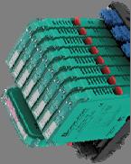
8 FF Power Supply General Purpose and With DCS System Connectors APPROVED
9 FF Power Supply Recommendations Each Segment shall have a dedicated FFPS FFPS shall be modular and hot Swappable FFPS shall be Isolated, Redundant and Load Sharing FFPS shall provide facilities for monitoring faults and failures FFPS rating shall allow longer home run / Trunk length to benefit user
10 FF Wiring Blocks


")

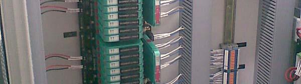
11 FF Wiring Blocks FOUNDATION fieldbus Wiring block is located where the trunk (home run) is connected to the various device spurs.
12 FF Wiring Blocks - Summary Only registered FOUNDATION fieldbus Wiring blocks shall be used The couplers shall have built-in spur short-circuit protection (to minimize the impact of a short at one device affecting the whole segment) Spur short-circuit protection shall have visual indication (on a spur level) when short-circuit protection is active and the spur's maximum current shall be limited by area classification and the current available to the network The couplers should provide visual indication of segment power as a minimum
13 FF Cables
14 Types of FF Cables The Physical Layer Specification of FOUNDATION Fieldbus defines four types of cables Type A Type B Type C Type D The max. cable length per segment of 1900m( trunk + Spurs) could be reached with cable type A only! In the meantime there are cables available type A with different cross sections
15 Types of Cables a = not specified
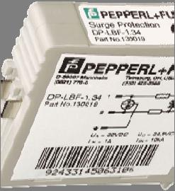
16 FF Surge Protectors Surge Protection ( 6.4 AG 181 V3.1) Surge protection for FOUNDATION fieldbus devices may be required in areas where induced voltage is an issue. This includes areas such as close wiring ii proximity it where large inductive loads are started and stopped, or areas known for lightning incidence. Surge suppression consists of a low-capacitance device installed at the device's electrical connection. It shall normally appear as an open circuit to the spur and segment to prevent any adverse effect on communications.
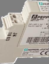
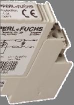


17 FF Surge Protectors
18 FF Surge Protectors - Summary Surge suppression device should not measurably attenuate the fieldbus signal Shall be installed at the Field Devices and host H1 Interface Current-limiting couplers ( Wiring Block spurs ) should not be used in combination with surge protectors. The surge protectors will cause failure of the current limiting circuits when a lightning strike occurs
 cable. The terminator is comprised of an RC network that provides 100 Ω impedance.")


19 FF Terminators FOUNDATION fieldbus segments require EXACTLY two terminators, one at each end of the trunk (home run) cable. The terminator is comprised of an RC network that provides 100 Ω impedance. The terminator allows the current-based FOUNDATION fieldbus communications signal tobeviewedasavoltage while being offset on the DC segment voltage supply. Most fieldbus power supplies and/or wiring blocks have a built-in segment terminator. Some wiring components have switchable terminators. Terminators at a field device shall not be used (due to the impact on the whole segment should the device need replacement)
20 FF Wiring Topologies Spur Topology (Bus with Spurs) This topology consists of fieldbus devices connected to a multi-drop bus segment through a length of cable called a spur. This technology is technically acceptable, but generally not a good economical choice when there is a high density of devices. Combination Topology Combinations of the above topologies must follow all the rules for maximum fieldbus network/segment length, and include the length of spurs in the total length calculation. These types of topologies are preferred for designs using bricks with tray cable. Spurs are permitted to extend only from trunk lines and not from other spur lines.
21 FF Wiring Topologies Daisy Chain Topology This topology consists of a network/segment that is routed from device to device, and is connected at the terminals of the fieldbus device. It should not be used, as it is unacceptable, for maintenance purposes.
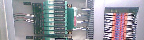
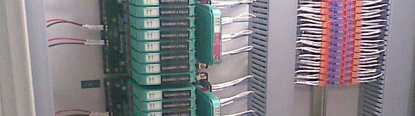
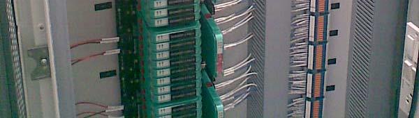
22 FF Wiring Topologies in Practice
23 General Purpose / Safe Area HOST DCS Accurate short circuit current limitation for each channel with LED indication FFPS Redundant / Load Sharing V V 230VAC 230VAC A fault at one instrument (e.g. short circuit) has no impact on the other outputs or on the segment Safe area


24 Fieldbus in Hazardous Area Redundant FISCO The first step Simplifying validation MAX power + FISCO Re-inventing Intrinsic Safety
25 Zone 2 Topology Zone2 Previous standards -Ex na ( Non arcing) / Ex nl ( energy Limiting) / Exic Intrinsically Safe -FNICO ( Non-Incendive) Current standard Exic From 2007 onwards Ex nl and FNICO standards are omitted and replaced by Ex ic ( similar to IS)

 has no impact on the other outputs or on the segment")
26 Zone 2 Hazardous Area Concept Ex nl / Ex ic HOST DCS Accurate short circuit current limitation for each channel with LED indication Ex na 17 to 30V, 500mA Ex nl / ic V V 230VAC 230VAC A fault at one instrument (e.g. short circuit) has no impact on the other outputs or on the segment Zone2
27 AG181 REVISION 3.1 Official FF Design Guidelines
28 Zone1 Topology Non-IS(EEx d) Trunk and spurs must be installed in increased safety EEx e IS ( FISCO, HPT, DART) A full intrinsically safe fieldbus segment (FISCO) Intrinsic safe trunk and spur Requires the use of IS Power Repeaters/Power Link module A mixture of EEx e and EEx I (High Power Trunk) Trunk has to be installed in increased safety Spurs are intrinsically safe Allows the use of Non IS Power Supplies/Power Repeaters/Power Links High Power Intrinsically safe (DART)
 Fieldbus")


29 Application Area - Zone 1 (EEx d) Fieldbus Power Hub Segment Protector Ex me Ex e V 230VAC V Instruments Ex d R-SP-E12 is resin filled as per Exd installation requirements Zone 1

 230VAC 16..32V 16.")
30 Application Area - Zone1 IS - HPT Resin Filling for Zone 1 Installation Exd Trunk live disconnect switch FieldBarrier Fieldbus Power Hub Zone 1 Ex e Ex ia (FISCO + Entity) 230VAC V V Zone 0/1
 16..32V Zone 0/1 230VAC 16 32V 16.")
31 Zone1 IS Enclosure solutions FieldBarrier Fieldbus Power Hub Zone 1 Ex e Ex ia (FISCO + Entity) V Zone 0/1 230VAC 16 32V V
32 DART Fieldbus DART Fieldbus The Simplicity of Intrinsic Safety DART fieldbus provides: A completely intrinsically safe fieldbus segment in gas groups IIB and IIC with real power redundancy with load sharing and advanced diagnostics The Intrinsically Safe High-Power Trunk DART Fieldbus is certified according to the international I.S. standard IEC


33 DART: Intrinsically safe High-Power Trunk Redundant, d three-port t isolated DART Power Supply General Purpose Area Zone 2 The intrinsically safe High-Power Trunk protected by DART DART Segment Protectors Intrinsically safe spurs Ex ib IIC with S/c protection Zone 1
34 Evolution of Various FF Hazardous Area Topologies Safe Area FISCO / FNICO FISCO Redundant HPT Field Barrier DART Segment Current Segment Voltage Redundancy Load Sharing FFPS Physical Layer Diagnostics Segment Design Mix Cabinet Space + + Initial Segment Cost (FFPS + Wiring Blocks) Live Trunk Working : Available : Not Available + : High : Low
35 FF Segment Design How to design Foundation Fieldbus segments?
36 Segment Design and Validation Tools Fieldbus allows to connect many devices on the same bus cable, but How many devices can I really connect? What cable should I use, and what cable distances can I really achieve? What happens in case of a short circuit in the field?
37 Segment Design and Validation Tools Graphical segment design tool example Download the NEW DesignMATE segment verification tool Various other tools are available with FF Vendors
38
39


40 FF Physical Layer Monitoring and Diagnosis
41 Fieldbus Diagnostic Capabilities Have Evolved ARC Report
42 Typical problems and how to solve them Tools to measure segment parameters (voltage, current) Tools to measure segment health (termination, noise) Tool to display EMC problems Tools to test communication Tool to measure cable degradation over time (trending) Tool to visualize signal quality of individual devices (noise, jitter, telegram level) Tool to allow remote access for expert


43 With Diagnostics of Physical Layer We Can. Commission Segments Monitor Segments Online Predictive Fault finding of Segments SEE KNOW ACT SEE what's going on in your physical layer KNOW when and how to act ACT in your Asset Management tool


44 Commissioning until now Always on the critical path Manual, step-by-step procedure Labor intensive Requires Screw driver Check sheet Pencil Multimeter Oscilloscope Connect one device at a time Disconnect after testing Test Report


45 Simple Commissioning Steps with ADM Verify address setting Wire up devices in the right location Check shielding Activate communication Use automated work procedures Testing Documentation All devices at once Wiring remains undisturbed! Test Report Commissioning Wizard


46 Commissioning Wizard With Expert System Support Takes snapshot Identifies wiring erros Ensures compliance with AG181 and IEC Recommends limits for ADM messages Stores limits in non-volatile memory Automatic Tag Readout Creates baseline report: Snapshot of all measurements Complete documentation ti Saves 80% of pre-commissioning time


47 Built-in fieldbus oscilloscope ADM provides expert tools for fast fault finding For diagnosing complex scenarios For the fieldbus expert With fieldbus specific triggers Captures up to 10 shots in a row SEE


48 Online monitoring KNOW The Advanced Diagnostic Module: Monitors physical layer health Detects changing conditions Sends messages with time stamps Expert System diagnoses faults: Precisely diagnoses causes Creates messages with clear text Enables proactive plant up keep Alerts before the segment fails


49 Online monitoring KNOW Clean layout shows boundaries Displays measurement values Highlights violations with color coding: Issues diagnostic messages Good value Maintenance required Out of specification


50 Diagnostic Menu ACT Expert System delivers clear text information for fast fault finding 1 Active messages 2 Actionable information with solution guideance based on expert system 3 History with timestamps When the failure occured disappeared Export function for external analysis and storage 1 2 3
51 The effect of Advanced Diagnostics Plan and purchase Install and commission Operate and maintain ACT Commission Monitor Troubleshoot Ca ash Flow SEE KNOW Longer plant uptime Know before you act Actionable information in clear text Verify against original design Automated checkout procedures Segment Checker: design of the physical layer
52 Conclusion Follow proper selection of components, design and installation guidelines System design guideline in AG 181 V3.1 will assist you to select right components for your Network Segment Design tools based on AG 181 V3.1 and IEC assist you to design your segments Always use Approved and registered products Right diagnostic tools helps to reduce installation and commissioning time


53 Thank You Fieldbus Foundation India Committee 21 st September, FFIC : Automation 2011 Mumbai
Design Benefits. Teo Puay Yong Pepperl+Fuchs. On Behalf of FF Marketing Society. The Future is Digital. 1 The Future is Digital
 Design Benefits The Future is Digital Teo Puay Yong Pepperl+Fuchs On Behalf of FF Marketing Society 1 The Future is Digital Design Benefits from Applying Foundation Fieldbus Bus structure and Wiring Loop
Fieldbus Foundation TM Physical Design. Joseph Khoo AP Regional Sales Director R.Stahl
 Fieldbus Foundation M Physical Design Joseph Khoo AP Regional Sales Director R.Stahl 1 Fieldbus How is fieldbus different to 4-20mA? Wiring and Interconnection Components opologies Design tools Installation
Introduction to Fieldbus Foundation Physical Layer
 Introduction to Fieldbus Foundation Physical Layer Fazi Hashim MTL Muhammad Syafiq bin Hamid KLAESB Product Sales /Application Engineer Email: muhammad.syafiq@klaesb.com Fieldbus What is fieldbus Benefits
Non-Incendive Fieldbus for Simplified Maintenance
 Non-Incendive Fieldbus for Simplified Maintenance 1 INTRODUCTION Many plants using FOUNDATION Fieldbus are installed in Class I Division 2 (Zone 2) hazardous area. Designers must choose a protection method
DC Power Considerations for Intrinsically Safe Applications
 Chapter 3 Intrinsically Safe Fieldbus Applications This chapter provides information about fieldbus applications that provide Intrinsically Safe (IS) power to fieldbus devices located in hazardous areas.
MANUAL SEGMENT CHECKER
 PROCESS AUTOMATION MANUAL SEGMENT CHECKER A UNIVERSAL AND EASY-TO- USE SEGMENT DESIGN TOOL FOR FIELDBUS NETWORKS With regard to the supply of products, the current issue of the following document is applicable:
The High Power Trunk Alternative to FISCO and FNICO
 The High Power Trunk Alternative to FISCO and FNICO Bernd Schuessler, Business Development Manager Pepperl+Fuchs Twinsburg, OH 330-486-0002 www.fieldconnex.info End users throughout the Fieldbus world
New FOUNDATION Fieldbus Interface Techniques Increased Availability and Reduced Costs. Andreas Agostin Pepperl+Fuchs
 New FOUNDATION Fieldbus Interface Techniques Increased Availability and Reduced Costs Andreas Agostin Pepperl+Fuchs Abstract InfraServ Hoechst and Aventis Pharma of Germany performed a comparison study
MANUAL Surge Protectors
 PROCESS AUTOMATION MANUAL Surge Protectors DP-LBF-I1.36.DE and DP-LBF- I1.36.IE With regard to the supply of products, the current issue of the following document is applicable: The General Terms of Delivery
High Availability Fieldbus Networks New Physical Layer Technologies. : Nagesha Nayak : Manager Project Pursuit
 High Availability Fieldbus Networks New Physical Layer Technologies Name Job Title Company : Nagesha Nayak : Manager Project Pursuit : Cooper -MTL What could possibly go wrong? Host H1 Card Control Room
FOUNDATION Fieldbus Fieldbus Basics & its Benefits
 FOUNDATION Fieldbus Fieldbus Basics & its Benefits James Loh Yokogawa Engineering Asia On behalf of Fieldbus Foundation TM Vietnam FF Seminar Fieldbus Basics - Agenda 1. H1 Basic Review. 2. H1 Benefits.
PROCESS AUTOMATION. Installation Technology for FOUNDATION Fieldbus
 PROCESS AUTOMATION Installation Technology for FOUNDATION Fieldbus HOST Plant Communication with Fieldbus page 4 Benefit from the future proof, enabling technology page 10 Power Supply Power your field
Tutorial: Characteristics & Requirements of Physical Networks in the Process Industry
 Tutorial: Characteristics & Requirements of Physical Networks in the Process Industry IEEE802.3cg 10 Mb/s Single Twisted Pair Ethernet Task Force Brian Franchuk Martin Zielinski Introduction 2 Pertinent
Benefits derived from the FF specification FF-831
 Foundation Fieldbus End Users Council Australia Inc. 9 Corcoran St Duncraig, WA 6023 P.O. Box Z5546 Perth, WA 6831 Benefits derived from the FF specification FF-831 Why we need it, and why it improves
10 Mb/s Single Twisted Pair Ethernet Process Industry Requirements Steffen Graber Pepperl+Fuchs
 10 Mb/s Single Twisted Pair Ethernet Process Industry Requirements Steffen Graber Pepperl+Fuchs IEEE802.3 10 Mb/s Single Twisted Pair Ethernet Study Group 9/8/2016 1 Overview Introduction Current bus Infrastructure
5 Fieldbus Technology
 5 Fieldbus Technology Ex e / Ex i 10922E00 The s Ex e/ex i connect intrinsically safe Foundation Fieldbus H1 or Profibus PA field devices to a non-intrinsically safe / Ex e trunk. Up to four intrinsically
High Availability Fieldbus Networks in Hazardous Areas
 High Availability Fieldbus Networks in Hazardous Areas Phil Saward MTL Instruments Automation 2011, Mumbai 21 st September 2011 In this presentation Foundation Fieldbus physical layer failure modes Keys
FOUNDATION. Product Overview. Foundation Fieldbus
 FOUNDATION Product Overview Foundation Fieldbus PROFIBUS PA Process Fieldbus wired infrastructure Control cabinet The Fieldbus (FB ) line of modular fieldbus components offers connectivity from the process
PROFIBUS and Integrated Safety architectures in Ex areas
 PROFIBUS and Integrated Safety architectures in Ex areas Since 1989, PROFIBUS has developed into a worldwide leading fieldbus system used in machine and process plant automation. The main reason why PROFIBUS
Diagnosis Concepts for Foundation H1 Physical Layer Diagnosis: from simple & effective to powerful & sophisticated
 Fieldbus Foundation India Committee Diagnosis Concepts for Foundation H1 Physical Layer Diagnosis: from simple & effective to powerful & sophisticated 1 Contents Why should we use diagnosis? What to diagnose
Segment Protector for Cabinet Installation R2-SP-IC* Features. Assembly. Function. Connection. Trunk, Ex na non-arcing. Spur.
 egment Protector for Cabinet nstallation Features Assembly 4... 12 outputs Ex ic (FCO or Entity) or non-incendive (Div 2) Advanced fault isolation at the spur egment Protector in Zone 2/Div. 2 nstruments
Distributed Intrinsically Safe Fieldbus Applications
 Application Note FB01-1 - Distributed Intrinsically Safe Fieldbus Applications Emerson Process Management DeltaV DCS System Pepperl+Fuchs June 2003 Application Note FB01-2 - c Pepperl+Fuchs Inc. All rights
PROCESS AUTOMATION INSTALLATION TECHNOLOGY FOR PROFIBUS PA
 PROCESS AUTOMATION INSTALLATION TECHNOLOGY FOR PROFIBUS PA SYSTEM OVERVIEW AND CONTENT HOST Plant Communication page 4 with Fieldbus Benefit from the future proof, enabling technology page 12 Segment coupler
Operating Instructions
 Introduction To protect the signal lines of field devices and systems in the cabinet against lightning. Pepperl+Fuchs covers the complete range of Surge Protection Barriers. Housing types Depending on
Segment Protector for Cabinet Installation R2-SP-IC* Features. Assembly. Function. Connection. Trunk, Ex na non-arcing. Spur.
 egment Protector for Cabinet nstallation Features Assembly 4... 12 outputs Ex ic (FCO or Entity) or non-incendive (Div 2) Advanced fault isolation at the spur egment Protector in Zone 2/Div. 2 nstruments
FOUNDATION Fieldbus Fieldbus Basics
 FOUNDATION Fieldbus Fieldbus Basics Nik Suzaimi Berkat Honeywell Sdn Bhd, MALAYSIA On behalf of Fieldbus Foundation TM End User Seminar 25 Oct 2010 Kuala Lumpur, MALAYSIA Agenda H1 Basic Review. What is
Appendix B MTL Power Supplies for Intrinsically Safe Fieldbus Applications
 Appendix B ML Power Supplies for Intrinsically Safe Fieldbus Applications he ML9121 and the ML9122 Power Supplies can be used to power field devices in hazardous areas for FCO (Fieldbus Intrinsically Safe
PROCESS AUTOMATION INSTRUCTION MANUAL FIELDBUS SURGE PROTECTOR F*-LBF-I1.32 F*-LBF-D1.32
 PROCESS AUTOMATION INSTRUCTION MANUAL FIELDBUS SURGE PROTECTOR F*-LBF-I1.32 F*-LBF-D1.32 With regard to the supply of products, the current issue of the following document is applicable: The General Terms
Assembly MAU. MUX 4 Channels 8 Channels Zone 1
 Multi-Input/Output Device for Cabinet Installation Features Assembly For discrete inputs and outputs Installation in Zone 1/Div. 1, intrinsically safe Sensors in Zone 0/Div. 1 Connection to fieldbus acc.
PROFIBUS Course Document Certified PROFIBUS Installer Course CPI Version 1.1 June 2011 Order No: PROFIBUS Learning Outcomes, Order No: 4.
 PROFIBUS Course Document Certified PROFIBUS Installer Course CPI Version 1.1 June 2011 Order No: 4.722 PROFIBUS Learning Outcomes, Order No: 4.722 Course Title: Course Code: Course Duration: Grading Type:
Trusted Strategic Partners in Process Automation. Alliance Member
 Trusted Strategic Partners in Process Automation Alliance Member Together with Pepperl+Fuchs, the Emerson Alliance Program provides a total automation solution Emerson and Pepperl+Fuchs have worked together
Assembly MAU. MUX 4 Channels 8 Channels Zone 1
 Multi-Input/Output Device for Cabinet Installation Features Assembly For discrete inputs and outputs Installation in Zone 1/Div. 1, intrinsically safe Sensors in Zone 0/Div. 1 Connection to fieldbus acc.
Commissioning Benefits
 Freedom to Choose. Power to Integrate. Commissioning Benefits Andreas Agostin MTL Instruments On behalf of Fieldbus Foundation Marketing Committee Freedom to Choose. Power to Integrate. Commissioning Benefits?
FB-6SP and FB-12SP. Block device couplers. Data sheet 3177_en_A. 2 Features. 1 Description
 Block device couplers Data sheet 3177_en_A 1 Description PHOENX CONTACT 2015-01-20 2 Features The and block couplers provide an interface between the fieldbus trunk cable and field devices on Foundation
FieldIT Multi Barrier NMB204/NMB204-EX (MB 204/MB 204-Ex)
") Data Sheet FieldIT Multi Barrier NMB204/NMB204-EX (MB 204/MB 204-Ex) Intrinsically safe power supply of up to 31 stations on the bus cascadable multi barrier Intrinsically safe connection of up to 4 field
Data Sheet FieldIT Multi Barrier NMB204/NMB204-EX (MB 204/MB 204-Ex) Intrinsically safe power supply of up to 31 stations on the bus cascadable multi barrier Intrinsically safe connection of up to 4 field
PROCESS AUTOMATION MANUAL F2-SP-IC*
 R PROCESS AUTOMATION MANUAL F2-SP-IC* Segment Protector With regard to the supply of products, the current issue of the following document is applicable: The General Terms of Delivery for Products and
Digital Output Module 8-Channel Version for Zone 2 Series 9475/
 > 8-channel digital output > Intrinsically safe outputs Ex ia > For Ex i solenoid valves and display elements > Line fault monitoring per channel > Diagnostics based on NE107 > Module can be replaced in
MARINE CERTIFIED PRODUCTS BY PEPPERL+FUCHS
 FIELDBUS Power Hub with Power Supply Modules KLD2-FBPS-1.25.360 HD2-FBPS-1.25.360 HD2-FBPS-1.500 HD2-FBPS-1.23.500 HD2-FBPS-1.17.500 Fieldbus Power Supply, 25 V/360 ma, stand-alone, DIN-rail mountable
PROCESS AUTOMATION SIMPLIFY PROCESSES FIELDCONNEX INFRASTRUCTURE FOR PROFIBUS PA
 PROCESS AUTOMATION SIMPLIFY PROCESSES FIELDCONNEX INFRASTRUCTURE FOR PROFIBUS PA SIMPLIFY PROCESSES The best solutions are usually very simple The fieldbus is a perfect example of simplicity at its best.
PROCESS AUTOMATION. MANUAL Compact Fieldbus Power Hub, Common Interface
 PROCESS AUTOMATION MANUAL Compact Fieldbus Power Hub, Common Interface With regard to the supply of products, the current issue of the following document is applicable: The General Terms of Delivery for
FIELDBUS IN ONGC C2C3 PLANT
 FIELDBUS IN ONGC C2C3 PLANT Agenda - FF Technology Conference GNFC, Bharuch on 4th February, 2011 MITHUN BISWAS AEE(I) ONGC PMC : Foster Wheeler Energy EPC : Toyo Engineering i India Limitedit DCS Vendor
PROCESS AUTOMATION YOUR PARTNER FOR INDUSTRY-SPECIFIC INSTALLATION SOLUTIONS FIELD JUNCTION BOX
 PROCESS AUTOMATION YOUR PARTNER FOR INDUSTRY-SPECIFIC INSTALLATION SOLUTIONS FIELD JUNCTION BOX OUR COMPONENTS... CONFIGURABLE TO YOUR NEEDS No application is like the others; every application always
7/2005. Reprint. Oldenbourg. Automation Technology in Practice. Breakthrough in Fieldbus technology High Power Trunk concepts.
 7/2005 July Automation Technology in Practice Breakthrough in Fieldbus technology High Power Trunk concepts Reprint Oldenbourg 3 Breakthrough in Fieldbus technology High Power Trunk concepts Do we see
Digital Output Module 4-Channel Version for Zone 1 Series 9475/
 www.stahl.de > 4-channel digital output > Intrinsically safe outputs Ex ib > Suitable for Ex i hydraulic valves and solenoid valves > Additional Ex i control input for (in accordance with IEC 61508 through
TYPE APPROVAL CERTIFICATE
 TYPE APPROVAL CERTIFICATE Certificate No: A-14038 File No: 899.60 Job Id: 262.1-017581-1 This is to certify: That the Peripheral Equipment with type designation(s) Fieldbus devices Issued to Pepperl+Fuchs
4 Remote I/O. Digital Output Module 8-Channel Version Type 9475/ from Rev. F
 4 Remote I/O Digital Output Module 8-Channel Version 8 channels for Ex i solenoid valves, piezo and booster-valves Intrinsically safe Ex ia IIC outputs Additional input for Plant-STOP available (acc. to
Digital Output Module 4-Channel Version for Zone 1 Series 9475/
 www.stahl.de > 4-channel digital output > Intrinsically safe outputs Ex ia > For Ex i solenoid valves and display elements > Additional Ex i control input for "Plant STOP" (acc. IEC61508 up to SIL2) >
Refer to attachment for more details. Andreas Meyer
 IECEx Certificate of Conformity INTERNATIONAL ELECTROTECHNICAL COMMISSION IEC Certification Scheme for Explosive Atmospheres for rules and details of the IECEx Scheme visit www.iecex.com Certificate No.:
FLEX Ex Spring Clamp Terminal Base
 Installation Instructions FLEX Ex Spring Clamp Terminal Base (Cat. No. 1797-TB3S) 1 10 11 4 Only remove this cover plug if connecting another terminal base unit. 3 5 6 12 2 7 8 9 41253 Component Identification
Safety instructions Overvoltage protection B81-35
 Safety instructions Overvoltage protection B81-35 IECEx BVS 15.0084X Intrinsic safety Document ID: 51001 Contents 1 Area of applicability... 3 2 General information... 3 3 Technical data... 5 4 Application
technical datasheet technical datasheet 9370-FB Series Fieldbus Barrier Enclosures, 6 or 12 spur
 technical datasheet technical datasheet 9370-FB Series Fieldbus Barrier Enclosures, 6 or 12 spur For Foundation fieldbus networks in hazardous areas Complete enclosure systems for 6 or 12 intrinsically
Operating Instructions. Intrinsically Safe Isolation Relay for Switches Model: REL manual_rel-6_0505
 Operating Instructions Intrinsically Safe Isolation Relay for Switches Model: REL-6003 manual_rel-6_0505 1. Contents 1. Contents...2 2. Note...3 3. Instrument Inspection...3 4. Regulation Use...3 5. Operating
Project Execution Best Practices
 Project Execution Best Practices Tips & Tricks based on lessons learnt 1 Successful Implementation & Improved Operation Temporary vs. Permanent Communication Ad-hoc Communication: Handheld field communicators
Cerabar S PMC71, PMP71, PMP ma HART, PROFIBUS PA, FOUNDATION Fieldbus
 Safety Instructions PMC71, PMP71, PMP75 4-20 ma HART, PROFIBUS PA, FOUNDATION Fieldbus Ex ia IIC T6 Ga/Gb IECEx KEM06.0011 0 XA00696P-D Safety instructions for electrical apparatus for explosion-hazardous
Digital Output Module 8-Channel Version for Zone 1 Series 9475/
 www.stahl.de > 8-channel digital output > Intrinsically safe outputs Ex ia > For Ex i solenoid valves and display elements > Additional Ex i control input for "Plant STOP" (acc. IEC61508 up to SIL2) >
ABB Fieldbus Infrastructure and Network Devices An overview
 ABB Fieldbus Infrastructure and Network Devices An overview ABB ABB fieldbus devices Industrial automation with the fieldbus Fieldbus technology is becoming increasingly important throughout industry.
About the FLEX Ex I/O Systems
 Section 2.1 About the FLEX Ex I/O Systems 1797 FLEX Ex I/O Overview FLEX Ex I/O offer: Adapter Terminal base I/O module Bus connectors Keyswitch FlexBus connectors 24V DC field power Terminal strips FLEX
TURCK Process Automation IS Interface Technology. Interface Modules. IM Series Cabinet
 Process Automation IS Interface Technology Interface Modules TURCK's IM series of Isolating Intrinsically Safe Barriers is designed to be a simple and safe way to solve the problems associated with the
10 Mb/s Single Twisted Pair Ethernet Power Distribution
 10 Mb/s Single Twisted Pair Ethernet Power Distribution Supporters: Matthias Wendt, Philips Lennart Yseboodt, Philips Steffen Graber Pepperl+Fuchs IEEE802.3 10 Mb/s Single Twisted Pair Ethernet Study Group
BA448CF-F FOUNDATION fieldbus Intrinsically safe Panel mounting 8 variable Fieldbus Indicator Issue 3
 BA448CF-F FOUNDATION fieldbus Intrinsically safe Panel mounting 8 variable Fieldbus Indicator Issue 3 Issue: 3 23 rd June 2011 2 CONTENTS 1. Description 1.1 Documentation 2. Operation 2.1 Error messages
Installation & Operation Manual
 Via Enrico Fermi, 2 I-25015 Desenzano del Garda (BS) - Italy Phone: +39 030 7870787 Fax: +39 030 7870777 www.solexy.net BAF Intrinsically Safe Ethernet Coupler for signals operating in Hazardous Areas
GE Intelligent Platforms PAC8000 RTU
 GE Intelligent Platforms PAC8000 RTU A ruggedized, reliable RTU PAC8000 Remote Terminal Unit (RTU) thrives in the desert heat of the Arabian Peninsula and the arctic cold of Siberian oil fields delivering
Foundation Fieldbus Technology Overview
 Foundation Fieldbus Technology Overview Mehul Vaidya Vice Chairman Foundation Fieldbus ME Marketing Committee (FFMEMC) Manager - Global Project Pursuit / Global Account Management PEPPERL+FUCHS ME FZE,
and Emerging Instrument Technologies
 FLUOR and Emerging Instrument Technologies SmartPlant Implementation Team By John Dressel The Challenge of Emerging Technologies New and emerging technologies bring new challenges to the Instrumentation
PROCESS AUTOMATION MANUAL FIELDBUS POWER HUB INVENSYS
 PROCESS AUTOMATION MANUAL FIELDBUS POWER HUB INVENSYS Advanced high performance power supplies and conditioner With regard to the supply of products, the current issue of the following document is applicable:
Introduction. Delivers four ports to provide increased input/ output per card. Takes advantage of all smart device capabilities
 DeltaV Distributed Control System M-series Foundation TM Fieldbus Product Data Sheet Series 2 Plus I/O Use DeltaV state-of-the-art Foundation Fieldbus Series 2 Plus redundant I/O for your process control
General. Remote I/O A4/1.
 www.stahl.de > Intrinsically safe Ex ia IIC, Ex e, Ex na or Ex nl inputs and outputs > Fieldbus communication: Modbus RTU, Profibus DP V0 and DP V1 HART, Industrial Ethernet, Modbus TCP, EtherNet/IP, PROFINET
M-series Foundation Fieldbus I/O
 DeltaV Distributed Control System Product Data Sheet M-series Foundation Fieldbus I/O Use DeltaV state-of-the-art FOUNDATION Fieldbus redundant I/O for your process control system. Increases input/output
PROFIBUS-PA PROFIBUS-DP. Field Communication PROFIBUS-DP/PA: Guidelines for planning and commissioning
 PROFIBUS-PA PROFIBUS-DP Field Communication PROFIBUS-DP/PA: Guidelines for planning and commissioning Profibus-DP/PA Overview able of Contents able of Contents Notes on Safety................. 3 1 Introduction......................
MTL8000-2/x Series Modular I/O
 -2/x Series Modular Overview Modules Modules - Overview - 2/2 components Use this option for general purpose or nonhazardous applications, or where the equipment and/or field wiring has to be mounted in
Digital Output Module 8-Channel Version for Zone 2 Series 9475/
 > 8-channel digital output > Intrinsically safe outputs Ex ia > For Ex i solenoid valves and display elements > Line fault monitoring per channel > Diagnostics based on NE107 > Module can be replaced in
BA488CF-P PROFIBUS PA Intrinsically safe Panel mounting Fieldbus Display issue 3
 TR Automatyka Sp. z o. o. Tel. (+48 022) 886 10 16 www.trautomatyka.pl ul. Lechicka 14 ; 02-156 Warszawa Fax. (+48 022) 846 50 37 biuro@trautomatyka.pl BA488CF-P PROFIBUS PA Intrinsically safe Panel mounting
S-series Foundation Fieldbus I/O
 DeltaV Distributed Control System Product Data Sheet S-series Foundation Fieldbus I/O Use DeltaV state-of-the-art S-series FOUNDATION fieldbus I/O for your process control system. Increase I/O capacity
APPLICATION GUIDE. Interface Modules IM Series.
 Interface Modules IM Series APPLICATION GUIDE www.turck.com Interface Technology Interface Modules TURCK's IM series of Isolating Intrinsically Safe Barriers is designed to be a simple and safe way to
Dual Module VCT. 5. Lexan Enclosure is Water & Corrosion Proof Contaminants will not affect the module as long as terminal strip is not immersed.
 2 The integrates position sensing, communication electronics, power outputs, auxiliary inputs and wire termination into a fully sealed compact package. The module also integrates a terminal strip directly
Safety Instructions Cerabar M PMC51, PMP51, PMP55
 XA00470P-B/00/EN/14.13 71224652 Products Solutions Services Safety Instructions PMC51, PMP51, PMP55 4-20 ma HART, PROFIBUS PA, FOUNDATION Fieldbus Ex ia IIC T6...T4 Ga/Gb Ex ia IIC T6...T3 Ga/Gb IECEx
How to calculate an Intrinsically Safe loop approval.
 MIE TALK - October 2016 How to calculate an Intrinsically Safe loop approval. EXPLOSIVE ATMOSPHERES Compile by: Gary Friend BSc PrEng, CEng MIET, Sales DirectorExtech Safety Systems (MTL, Beka Associates,
Micro Motion Model 2200S 2-Wire Transmitter with MVD Technology
 Product Data Sheet PS-001094, Rev. C September 2009 Micro Motion Model 2200S 2-Wire Transmitter with MVD Technology The Micro Motion Model 2200S 2-wire transmitter enables the use of reliable and accurate
6 Reasons to Give PROFIBUS PA Another Look
 6 Reasons to Give PROFIBUS PA Another Look #1 PROFIBUS a Proven Technology Fieldbus systems have a proven track record that goes back to the early 1990 s, and PROFIBUS has been at the forefront. These
Foundation Fieldbus. actuator control. Established Leaders in Actuation Technology. Foundation Fieldbus. Freedom to Choose, Power to Integrate
 Established Leaders in Actuation Technology Foundation Fieldbus actuator control Freedom to Choose, Power to Integrate Foundation Fieldbus Serial communication and control of Rotork actuators Publication
Foundation Fieldbus A DCS Perspective
 Foundation Fieldbus A DCS Perspective Name Sandeep Redkar Title Technical Consultant 23 rd November 2012 1 Agenda DCS System Readiness System Architecture System Engineering and Diagnostics System Commissioning
F101, F102, F104. Relcom Installation Instructions. Fieldbus Power Supply F101-PS
 F101, F102, F104 Fieldbus Power Supply F101-PS Installation Instructions Relcom www.mtl-fieldbus.com CONTENTS PAGE 1 OVERVIEW 2 2 DESCRIPTION 2 3 COMPONENTS AND ACCESSORIES 2 4 MECHANICAL 3 4.1 Mounting
FIELDBUS ENGINEER S GUIDE
 PROCESS AUTOMATION FIELDBUS ENGINEER S GUIDE About Pepperl+Fuchs Pepperl+Fuchs is a leading developer and manufacturer of electronic sensors and components for the global automation market. Since more
Installing Fieldbus: Some practical advice, Part 1
 Installing Fieldbus: Some practical advice, Part 1 By: Mike O Neill, Director, International Sales MooreHawke, a Division of Moore Industries Many automation engineers are coming face to face with real
Installation Instructions
 Installation Instructions (Catalog Number 1771-OD) This document provides information on: Because of the variety of uses for the products described in this publication, those responsible for the application
Hazardous Area Protection
 Hazardous Area Protection Global Solutions in Hazardous Area Surge and Lightning Protection Intrinsic Safety When instrumentation is installed in a potentially explosive environment steps must be taken
DCS and Fieldbus Foundation. Shivaji Day Process Automation, ABB
 DCS and Fieldbus Foundation Shivaji Day Process Automation, B Foundation Fieldbus Specification FOUNDATION Fieldbus HSE - Server Integration - HSE is the Open Common interface for access to the server
Myths and Actual Practice with Industrial Data Communications and Hazardous Areas. Steve Mackay IDC Technologies
 Myths and Actual Practice with Industrial Data Communications and Hazardous Areas Steve Mackay IDC Technologies Myths and Best Practice Practical examination of data communications systems in hazardous
M-series Profibus DP Series 2 Plus Interface Card
 DeltaV Distributed Control Systems Product Data Sheet M-series Profibus DP Series 2 Plus Interface Card The DeltaV M-series Profibus DP Interface Card provides the solution for interfacing to discrete
PI-EX-ME-2NAM/COC-120VAC
 PI-EX-ME-NAM/COC-0VAC Ex-i NAMUR Isolation Amplifier, With Intrinsically Safe Input and Relay Output, PDT, Two-Channel, 0 V AC Supply INTERFACE Data Sheet 0944_00_en PHOENIX CONTACT - 0/008 Description
Installing Fieldbus. Installing Fieldbus
 Installing Installing Many automation engineers are coming face to face with real fieldbus applications for the first time. (the use of digital communications networks for distributed instrumentation and
F11 Fieldbus Power Hub
 technical datasheet technical datasheet F11 Fieldbus Power Hub power conditioner with terminators for fieldbus networks built-in fieldbus power conditioning 5 fieldbus device ports 30mA current per device
S-series H1 I/O Card with Integrated Power
 January 2013 Page 1 S-series H1 I/O Card with Integrated Power Use DeltaV state-of-the-art for your process control system. Increase I/O capacity while reducing wiring Maximize smart device capabilities
Technical Information. FOUNDATION Fieldbus PID 110 AI 110 AO 110. Part 4 Communication
 Technical Information FOUNDATION Fieldbus 4 Part 4 Communication AI 110 PID 110 AO 110 Technical Information Part 1: Fundamentals Part 2: Self-operated Regulators Part 3: Control Valves Part 4: Communication
Intrinsically Safe Barriers
 Intrinsically Safe Barriers Description Page No. Safety Barriers 464-472 Din Rail Isolated Barriers 473-488 477 Intrinsically Safe Barriers Product Overview We have simplified intrinsic safety! Cooper
SIMATIC. Process Control System PCS 7 PCS 7 Documentation (V8.1) Options for Accessing Documentation 1. Documentation for the Planning Phase 2
 Options for Accessing Documentation 1. Documentation for the Planning Phase 2") Options for Accessing Documentation 1 Documentation for the Planning Phase 2 SIMATIC Process Control System PCS 7 Documentation for the Realization Phase 3 Documentation on commissioning, operation, diagnostics
Options for Accessing Documentation 1 Documentation for the Planning Phase 2 SIMATIC Process Control System PCS 7 Documentation for the Realization Phase 3 Documentation on commissioning, operation, diagnostics
Electrical Demand Specification (Reference SOP: )
") Project: Equipment Description: Location: Equipment No.: Project No: Protocol No.: Content Index 1. GENERAL...3 Design Standards...3 1.1. Standards...3 2. DESIGN...3 2.1. Safety...3 2.2. Circuit protection...3
Project: Equipment Description: Location: Equipment No.: Project No: Protocol No.: Content Index 1. GENERAL...3 Design Standards...3 1.1. Standards...3 2. DESIGN...3 2.1. Safety...3 2.2. Circuit protection...3
INSTRUCTION MANUAL. Universal AC Input Switching Power Supply 24 Vdc Output DIN-Rail Models PSD1000, PSD1000F PSD PSD1000F
 PSD1000 - PSD1000F INSTRUCTION MANUAL Universal AC Input Switching Power Supply 24 Vdc Output DIN-Rail Models PSD1000, PSD1000F PSD1000 - Universal AC Input Switching Power Supply 24 Vdc Output ISM0089-4
Cabling Installation - Procedures
 Cabling Installation - Procedures Installing Twisted-Pair Media Topology: Ensure the topology chosen is appropriate for the transceiver in question: bus for TP/XF-1250 channels and either bus or free topology
DeltaV SIS TM. Logic Solver. DeltaV SIS Logic Solver. Introduction. DeltaV SIS Product Data Sheet. World s first smart SIS Logic Solver
 February 2016 Page 1 DeltaV SIS TM Logic Solver The DeltaV SIS platform is the world s smart SIS system to use the power of predictive intelligence for increasing the availability of the entire safety