ControlWave Process Automation Controller
|
|
|
- Marvin Rodgers
- 6 years ago
- Views:
Transcription


1 Instruction Manual Doc Number CI-ControlWave Part Number D301381X012 August 2015 ControlWave Process Automation Controller Remote Automation Solutions
2 IMPORTANT! READ INSTRUCTIONS BEFORE STARTING! Be sure that these instructions are carefully read and understood before any operation is attempted. Improper use of this device in some applications may result in damage or injury. The user is urged to keep this book filed in a convenient location for future reference. These instructions may not cover all details or variations in equipment or cover every possible situation to be met in connection with installation, operation or maintenance. Should problems arise that are not covered sufficiently in the text, the purchaser is advised to contact Emerson Process Management, Remote Automation Solutions for further information. EQUIPMENT APPLICATION WARNING The customer should note that a failure of this instrument or system, for whatever reason, may leave an operating process without protection. Depending upon the application, this could result in possible damage to property or injury to persons. It is suggested that the purchaser review the need for additional backup equipment or provide alternate means of protection such as alarm devices, output limiting, fail-safe valves, relief valves, emergency shutoffs, emergency switches, etc. If additional information is required, the purchaser is advised to contact Remote Automation Solutions. RETURNED EQUIPMENT WARNING When returning any equipment to Remote Automation Solutions for repairs or evaluation, please note the following: The party sending such materials is responsible to ensure that the materials returned to Remote Automation Solutions are clean to safe levels, as such levels are defined and/or determined by applicable federal, state and/or local law regulations or codes. Such party agrees to indemnify Remote Automation Solutions and save Remote Automation Solutions harmless from any liability or damage which Remote Automation Solutions may incur or suffer due to such party's failure to so act. ELECTRICAL GROUNDING Metal enclosures and exposed metal parts of electrical instruments must be grounded in accordance with OSHA rules and regulations pertaining to "Design Safety Standards for Electrical Systems," 29 CFR, Part 1910, Subpart S, dated: April 16, 1981 (OSHA rulings are in agreement with the National Electrical Code). The grounding requirement is also applicable to mechanical or pneumatic instruments that include electrically operated devices such as lights, switches, relays, alarms, or chart drives. EQUIPMENT DAMAGE FROM ELECTROSTATIC DISCHARGE VOLTAGE This product contains sensitive electronic components that can be damaged by exposure to an electrostatic discharge (ESD) voltage. Depending on the magnitude and duration of the ESD, this can result in erratic operation or complete failure of the equipment. Read supplemental document S14006 for proper care and handling of ESD-sensitive components.
3 Contents Chapter 1 Introduction Scope of the Manual Physical Description Housings CPU Module Power Supply/Sequencer Module (PSSM) I/O Modules Software Tools Secure Gateway Chapter 2 Installation Site Considerations Class I, Div 2 Installation Considerations Installation Overview Unpacking Components Color Coding of Slot Connectors Mounting the Housing Grounding the Housing Power Supply/Sequencer Module (PSSM) General Information about the PSSM PSSM Installation Overview Setting Jumpers General Wiring Guidelines Wiring a Bulk DC Power Supply to the PSSM Hot-swapping a Power Supply Wiring an External Alarm or Annunciator to the Watchdog Connector and Wiring the Redundancy Control Input (OPTIONAL) Wiring Digital Inputs to indicate Power Supply Failure PSSM Specifications CPU Module Setting DIP Switches on the CPU Module Connections to RS-232 Serial Port(s) Connections to RS-485 Serial Port(s) on tsecondary Communication Board (SCB) Connections to Ethernet Port(s) on the CPU Module Bezels Chapter 3 I/O Modules Module Placement Status LEDs Wiring Local Termination Remote Termination Shielding and Grounding Digital Input (DI) Modules Digital Output (DO) Modules Analog Input (AI) Modules Analog Output (AO) Modules Universal Digital Input (UDI) Modules Isolated Resistance Temperature Device (RTD) Input Module Isolated Thermocouple Module Issued Aug-2015 Contents iii
4 Chapter 4 Operation Powering Up/Powering Down the ControlWave Communicating with the ControlWave Default Comm Port Settings Changing Port Settings Collecting Data from the ControlWave Creating and Downloading an Application (ControlWave Project) Creating and Maintaining Backups Creating a Zipped Project File (*.ZWT) For Backup Saving Flash Configuration Parameters (*.FCP) Backing up Data Chapter 5 Service and Troubleshooting Upgrading Firmware Removing or Replacing Components Accessing Modules for Testing Removing/Replacing the Bezel Removing/Replacing the CPU Module Removing/Replacing the PSSM Removing/Replacing an I/O Module (Hot Swapping) Removing/Replacing the Backup Battery General Troubleshooting Procedures Common Communication Configuration Problems Checking LEDs Checking Wiring/Signals Port 80 Display Codes Reset Switch WINDIAG Diagnostic Utility Available Diagnostics Core Updump Appendix A Special Instructions for Class I, Division 2 Hazardous Locations A-1 Appendix Z Sources for Obtaining Material Safety Data Sheets Z-1 Index IND-1 iv Contents Issued Aug-2015
5 Chapter 1 Introduction In This Chapter This manual focuses on the hardware aspects of the ControlWave Process Automation Controller (called the ControlWave throughout the rest of this manual). For information about the software used with the ControlWave, refer to the ControlWave Quick Setup Guide (D5084), the ControlWave Designer Programmer s Handbook (D5125), and the online help in ControlWave Designer. This chapter details the structure of this manual and provides an overview of the ControlWave and its components. 1.1 Scope of the Manual Physical Description Housings CPU Module Power Supply/Sequencer Module (PSSM) I/O Modules Software Tools Secure Gateway ControlWave products have been designed and integrated as a highly adaptable, high performance distributed open controller family with exceptional networking capability that provides a complete process automation management solution for the natural gas, water, and wastewater industries. The ControlWave was designed with an emphasis on providing high performance with low power consumption, scalability, and modularity. Features ControlWave process automation controllers have the following key features: Low power consumption Wide operating temperature range: ( 40 to +70 C) ( 40 to 158 F) Small size (enabling panel mount or 19 inch rack-mount installations) Two RS-232 ports One 10/100 MB Ethernet port Optional secondary communication board (SCB) provides additional options for RS-232, RS-485, and Ethernet communications Housings to support four or eight I/O modules Variety of I/O modules and support for hot swapping of I/O modules Support for redundant operation with another ControlWave process automation controller LED status indicators on the CPU, PSSM, and certain I/O modules Revised Aug-2015 Introduction 1-1
6 1.1 Scope of the Manual 1.2 Physical Description Port 80 display to present status codes Battery backup for the real-time clock and the system s static RAM (SRAM) Class I, Division 2 Hazardous Location approvals This manual contains the following chapters: Chapter 1 Introduction Chapter 2 Installation Chapter 3 I/O Modules Chapter 4 Operation Chapter 5 Service and Troubleshooting Provides an overview of the hardware and general specifications for the ControlWave. Provides information on the housings, the Power Supply/Sequencer module (PSSM), and the CPU module. Provides general information and wiring diagrams for the I/O modules. Provides information on day-to-day operation of the ControlWave. Provides information on service and troubleshooting procedures. Each ControlWave has a printed circuit board (PCB) backplane mounted in a stainless steel housing, a Power Supply/Sequencer Module (PSSM), a CPU module which may include an optional Secondary Communication Board (SCB) and depending on the backplane and housing size up to eight I/O modules. Figure 1-1. ControlWave with 8 I/O Modules Refer to the following sections in this chapter or to other chapters in this manual for further information: Housings (chassis) with backplanes (see Section 1.3 and Chapter 2) 1-2 Introduction Revised Aug-2015
7 Power Supply/Sequencer module (PSSM) (see Section 1.5 and Chapter 2) CPU module (see Section 1.4 and Chapter 2) One or more I/O modules (see Section 1.6 and Chapter 3) 1.3 Housings ControlWave housings are stainless steel designed for panel-mounting or for some versions, for mounting in a 19-inch equipment rack. They contain the printed circuit board (PCB) backplane into which you connect the PSSM, the CPU module, and any I/O modules. The following housings are available: 6-slot backplane supports one PSSM, one CPU, and up to four I/O modules. 10-slot housing supports one PSSM, one CPU, and up to eight I/O modules. The 10-slot housing is suitable for mounting in a 19-inch equipment rack. Note: For detailed technical specifications, please see document CWPAC available on our website Revised Aug-2015 Introduction 1-3


8 Figure 1-2. ControlWave Housing Options 1-4 Introduction Revised Aug-2015
9 1.4 CPU Module Part Number CPU Module Configurations ControlWave Instruction Manual The CPU (central processing unit) module houses the multi-layer PCB, which contains the ControlWave CPU, I/O monitor/control, memory, and communication functions. It also may include the optional Secondary Communications Board (SCB). The CPU module includes: AMD Elan SC520 microprocessor running at 100 MHz two RS-232 communication ports one 10/100baseT Ethernet port 2 MB of battery backed Static RAM (SRAM) 64 MB of Synchronous Dynamic RAM (SDRAM) 512 KB boot/downloader FLASH 32 MB simultaneous read/write FLASH memory transmit (TX) and receive (RX) LEDs for each communication port Keyed run/remote/local operation switch configuration DIP switches (described in Chapter 2) Port 80 display to show status codes You can order the CPU module with the optional secondary communication board (SCB) for additional communication ports. See CPU Module Configurations. Number of RS-232 Ports The CPU module has several basic configurations, all of which have an on-board backup battery and different combinations of communications ports. Table 1-1. CPU Module Configurations Number of RS- 485 Ports Number of Ethernet Ports No SCB. Notes For this port count, 1 RS-232 port and 1 RS-485 port reside on the SCB For this port count, 1 RS-232 port,1 RS-485 port, and 2 Ethernet ports reside on the SCB For this port count, both RS- 485 ports and 2 Ethernet ports reside on the SCB. CPU Backup Battery The CPU module includes a 3.6V, 950 ma-hr lithium ½ AA battery. This battery provides backup power for the real-time clock, CMOS RAM (within the microprocessor) and the system s Static RAM (SRAM). Revised Aug-2015 Introduction 1-5
10 CPU Memory There are several different types of memory used on the CPU module: Boot/Downloader FLASH Boot/download code is contained in a single 512 Kbyte FLASH chip. Boot FLASH also holds the value of soft switches, audit/archive file configurations, and user account and port information. FLASH Memory The CPU module contains 32 MB of FLASH memory. The FLASH memory holds the system firmware and the boot project. Optionally FLASH memory also stores the zipped ControlWave project (*.zwt), user files, and historical data (audit/archive files).the FLASH does not support hardware write protection. System Memory (SRAM) The CPU module has 2 MB of static random access memory (SRAM). During power loss periods, SRAM enters data retention mode (powered by the CPU backup battery). Critical system information that must be retained during power outages or when the system has been disabled for maintenance is stored here. This includes the last states of all I/O points, audit/archive historical data (if not stored in FLASH), the values of any variables marked RETAIN, the values of any variables assigned to the static memory area, and any pending alarm messages not yet reported. SDRAM The CPU module contains 64MB of synchronous dynamic random access memory (SDRAM). SDRAM holds the running application (ControlWave project) as well as a copy of system firmware and the current values of any variables not marked RETAIN or stored in the static memory area. This allows the system to run faster than it will from the SRAM memory. SDRAM is not battery-backed. CMOS RAM The Elan microprocessor includes 124 bytes of complementary metal oxide semiconductor (CMOS) RAM to hold various internal parameters. 1-6 Introduction Revised Aug-2015
11 1.5 Power Supply/Sequencer Module (PSSM) The Power Supply/Sequencer module (PSSM) takes power from an external bulk DC power supply and then provides power through the ControlWave housing/backplane to all installed modules. You can order it with either a single on-board power supply or dual onboard power supplies to support hot-swapping of a power supply if one should fail. The PSSM operates from to +30V (dc) and ships from the factory with a nominal input supply configuration of 24V. The PSSM includes: ON/OFF system supply switch(es) Pluggable terminal block to connect the external power supply Watchdog output connector to signal a watchdog failure to an external device Status LEDs Chapter 2 includes instructions for installing and configuring the PSSM. 1.6 I/O Modules The ControlWave supports analog input, analog output, digital input, digital output, universal digital input, isolated RTD, and isolated low level analog (thermocouple and mv) input modules for either local or remote field device wiring termination. Refer to Chapter 3 for information on specific I/O modules. Figure 1-3 shows a typical I/O module housing. Terminations are pluggable and accept a maximum wire size of #14 AWG. All I/O modules have surge protection that meets either C or IEEE specifications. Each I/O module connects to the backplane using a 110-pin male connector and to its associated terminal block assembly using a 44 pin header. Revised Aug-2015 Introduction 1-7
12 Figure 1-3. I/O Module (with door open) 1.7 Software Tools The ControlWave programming environment consists of a set of integrated software tools which allow you to create, test, implement, and download complex control strategies for use with the ControlWave. Figure 1-4 graphically presents the programming environment. The tools which make up the programming environment include: ControlWave Designer is your load-building package. It offers several different methods for you to create control strategy programs that run in your ControlWave. You can use pre-made function blocks, ladder logic, or structured languages. The resulting process control strategy programs (called projects) are fully compatible with IEC standards. For information on ControlWave Designer, see the Getting Started with ControlWave Designer manual (document D5085), the ControlWave Quick Setup Guide (document D5084), and the ControlWave Designer Programmer s Handbook (document D5125). 1-8 Introduction Revised Aug-2015
13 Figure 1-4. ControlWave Programming Environment The I/O Configurator, accessible via a menu item in ControlWave Designer, allows you to define process I/O modules in the ControlWave and configure the individual mapping of I/O points for digital and analog inputs and outputs. For information on the I/O Configurator see the ControlWave Designer Programmer s Handbook (document D5125). The ACCOL3 Firmware Library, available within ControlWave Designer, includes a series of ControlWave-specific function blocks. These pre-programmed function blocks let you accomplish various tasks common to most user applications including alarming, historical data storage, as well as process control algorithms such as PID control. For information on individual function blocks, see the online help within ControlWave Designer. OpenBSI Utilities provides a set of programs that allow you to configure a communication network of ControlWave controllers, download files to the controllers, and collect data from the network. OpenBSI also exports data from the network to a SCADA/host package, such as OpenEnterprise. For information on configuring OpenBSI communications, see the OpenBSI Utilities Manual (document D5081). OpenBSI Harvester is a special add-on package that allows scheduled data collections from large networks. For information on the Harvester, see the OpenBSI Harvester Manual (document D5120). Revised Aug-2015 Introduction 1-9
14 A series of web page controls are available for retrieval of real-time data values and communication statistics. These controls utilize ActiveX technology and are called through a set of fixed web pages, compatible with Microsoft Internet Explorer. Alternatively, developers can place the controls in third-party ActiveX compatible containers such as Visual BASIC or Microsoft Excel. For information on the ActiveX controls, see the Web_BSI Manual (document D5087). User-defined web pages - If desired, you can use the ActiveX web controls in your own user-defined web pages you can store at the PC to provide a customized human-machine interface (HMI). Flash Configuration Utility Parameters such as the BSAP local address, IP address, etc. are set using the Flash Configuration Utility, accessible via OpenBSI LocalView, NetView, or TechView. For information on the Flash Configuration Utility, see Chapter 5 of the OpenBSI Utilities Manual (document D5081). Communication Protocols 1.8 Secure Gateway In addition to the Bristol Synchronous/Asynchronous Protocol (BSAP), ControlWave supports communications using: Internet Protocol (IP) - You can use an Ethernet port or use a serial port using serial IP using Point-to-Point Protocol (PPP). Other supported protocols include: Modbus, Allen-Bradley DF1, CIP, DNP3, and Hex Repeater. See the ControlWave Designer online help for details and restrictions. For enhanced data security when using an IP/Ethernet connection, Emerson Remote Automation Solutions recommends adding an industrial router with VPN and firewall security. Recommended solutions include the MOXA EDR 810, the Hirschman Eagle One, or the Phoenix mguard rs4000 (or equivalents). An example of how to install one of these devices to the RTU can be found in the Emerson Remote Automation Solutions MOXA Industrial Secure Router Installation Guide (part number D301766X012). For further information, contact your Local Business Partner or the individual vendor s website Introduction Revised Aug-2015
15 Chapter 2 Installation In This Chapter This chapter discusses the physical configuration of the ControlWave, considerations for installation, wiring instructions for the PSSM module, and instructions for setting switches and jumpers on the CPU module. For instructions on I/O installation, see Chapter Site Considerations Class I, Div 2 Installation Considerations Installation Overview Unpacking Components Color Coding of Slot Connectors Mounting the Housing Grounding the Housing Power Supply/Sequencer Module (PSSM) General Information about the PSSM PSSM Installation Overview Setting Jumpers General Wiring Guidelines Wiring a Bulk DC Power Supply to the PSSM Hot-swapping a Power Supply Wiring an External Alarm or Annunciator to the Watchdog Connector and Wiring the Redundancy Control Input (OPTIONAL) Wiring Digital Inputs to indicate Power Supply Failure PSSM Specifications CPU Module Setting DIP Switches on the CPU Module Connections to RS-232 Serial Port(s) Connections to RS-485 Serial Port(s) on the Secondary Communication Board (SCB) Connections to Ethernet Port(s) on the CPU Module Bezels Site Considerations Caution When choosing an installation site, check all clearances. Ensure that the ControlWave is accessible for wiring and service. To ensure safe use of this product, please review and follow the instructions in the following supplemental documentation: Supplement Guide - ControlWave Site Considerations for Equipment Installation, Grounding, and Wiring (S1400CW) ESDS Manual Care and Handling of PC Boards and ESD Sensitive Components (S14006) Revised Aug-2015 Installation 2-1
16 Specifications for Temperature, Humidity and Vibration Caution See document CWPAC available on our website for detailed technical specifications for temperature, humidity, and vibration for the ControlWave. This document is available on our website at: Ensure that the ambient temperature and humidity at the installation site remains within these specifications. Operation beyond the specified ranges could cause output errors and erratic performance. Prolonged operation under extreme conditions could also result in failure of the unit. Check the mounted enclosure, panel, or equipment rack for mechanical vibrations. Make sure that the ControlWave is not exposed to a level of vibration that exceeds that provided in the technical specifications.. Placement of the ControlWave in Class 1, Division 2 (Group A, B, C, and D) hazardous locations requires that you select an appropriate enclosure that meets NEMA Type 3X or 4X specifications Class I, Div 2 Installation Considerations Underwriters Laboratories (UL) lists the ControlWave as non-incendive and suitable only for use in Class I, Division 2, Group A, B, C, and D hazardous locations and non-hazardous locations. Read this chapter and Appendix A carefully before you install a ControlWave in a hazardous location. Perform all power and I/O wiring in accordance with Class I, Division 2 wiring methods as defined in Article (b) of the National Electrical Code, NFPA 70 (for installations within the United States) or as specified in Section of the Canadian Electrical Code (for installation in Canada). WARNING EXPLOSION HAZARD Substitution of components may impair suitability for use in Class I, Division 2 environments. When the ControlWave is situated in a hazardous location, turn off power before servicing or replacing the unit and before installing or removing I/O wiring. Do not connect or disconnect equipment unless the power is switched off or the area is known to be non-hazardous. 2-2 Installation Revised Aug-2015
17 2.2 Installation Overview Installing a ControlWave involves several general steps: 1. Unpacking, assembling, and configuring the hardware 2. Installing PC-based software (ControlWave Designer) 3. Establishing communications 4. Creating an application-specific control strategy (ControlWave project). 5. Creating application-specific web pages (optional) 6. Adding the ControlWave to an OpenBSI network 7. Downloading the application-specific ControlWave project into the ControlWave Note: Steps 2 through 7 require that you install and use ControlWave Designer software on your PC. This manual focuses on hardware installation and preparation. Software installation and configuration is beyond the scope of this manual. Refer to the ControlWave Quick Setup Guide (D5084) for material related to software installation and use Unpacking Components Packaging Depending upon how you order it, the ControlWave may arrive preassembled, with all modules installed in the housing, or as individual components in a number of separate boxes. In the latter case, you must identify, unpack, and assemble the components. Unless otherwise noted, you can place I/O modules in any slot in a base or expansion housing. Note: Do not install modules in the housing until you have mounted and grounded the housing at the designated installation site. Delivered boxes may include: Housing assemblies Power Supply/Sequencer module (PSSM) Note: The PSSM must reside in slot #1 in the base housing. CPU module Note: The CPU module must reside in slot #2 in the base housing. Revised Aug-2015 Installation 2-3
18 I/O Modules Notes: There are many different types of I/O modules available. Chapter 3 contains detailed instructions on each I/O module. Universal Digital Input (UDI) modules can only reside in the first four I/O slots. One or more bezel assemblies; each bezel covers two I/O modules Color Coding of Slot Connectors A color tab on each backplane connector matches the color on the module which you can place in that slot. PSSM goes in the first slot (Yellow tab) CPU goes in the second slot (Blue tab) I/O modules go in any other slot (Green tab) Mounting the Housing You can install a ControlWave equipped with a 4-I/O module housing on a wall or panel. See Figure 2-2 for mounting hole patterns for a 4- I/O unit. You can install a ControlWave equipped with an 8-I/O module housing in a 19-inch equipment rack, a panel or a wall. These units ship from the factory with the end plates configured for 19-inch rack mounting. Remove the end plates, rotate them 180 and then reinstall them to accommodate panel or wall mounting. See Figure 2-1 for hole patterns and dimensions. When you install any of these units on a panel or wall, position it according to the following restrictions: Position the unit so that you can see the front of the assembly and so it is accessible for service such as installing a module or replacing a battery. Do not install ControlWave modules until you mount the housing and ground it properly. 2-4 Installation Revised Aug-2015

19 Figure I/O Module ControlWave - Mounting Diagram Revised Aug-2015 Installation 2-5
20 Figure I/O Module ControlWave - Mounting Diagram Grounding the Housing Caution Do not install any modules in the housing until you mount and ground the housing at the designated installation site. Housings have a ground lug that accommodates up to a #4 AWG wire size. Once you install the housing, you must run a ground wire between the housing ground lug and a known good earth ground. When you install the various ControlWave modules into the housing and secure them using the captive panel fasteners, this automatically connects them to chassis ground. 2-6 Installation Revised Aug-2015
21 Note: After you install the PSSM in the housing, as an added precaution we recommend that you run a #14 AWG wire from the TB2-3 power connection (chassis ground) to the same known good earth ground. Additional grounding guidelines include: Use stranded copper wire (#4 AWG) for the housing to earth ground, and keep the length as short as possible. Clamp or braze the ground wire to the ground bed conductor (typically a stranded copper AWG 0000 cable installed vertically or horizontally). Tin the wire ends with solder (using a high-wattage soldering iron) prior to inserting the wire into the housing ground lug. Run the ground wire so that any routing bend in the cable has a minimum radius of 12-inches below ground and 8-inches above ground. 2.3 Power Supply/Sequencer Module (PSSM) Before we actually install the PSSM it in the housing, we re going to discuss some general information about how it works General Information about the PSSM The Power Supply/Sequencer module (PSSM) takes power from an external bulk DC power supply and then provides power through the ControlWave housing/backplane to all installed modules. The PSSM is used in the following ControlWave models: ControlWave Process Automation Controller ControlWave I/O Expansion Rack ControlWave Redundant Controller The PSSM plugs into slot #1 (first slot from the left) on the ControlWave s backplane using connector J1. The PSSM provides your ControlWave with dual power supplies for operational redundancy. Note: You can optionally purchase the PSSM with only a single power supply installed, however, this configuration does not allow for redundancy within the PSSM which is discussed throughout this section. The PSSM includes two independent power supplies. Should either power supply fail, operations automatically continue using the second supply, and you can hot-swap the failed power supply with a spare unit without interrupting control operations. The PSSM also supports hot swapping of I/O modules. However, you cannot replace the entire PSSM itself without first turning off power to the ControlWave. Revised Aug-2015 Installation 2-7
22 Power Supply WARNING Hot Swap of I/O Modules Hot Swapping of Power Supplies Watchdog Switch Redundancy Control Input When used as part of a redundant system, the failure of one of the two power supplies in a redundant power supply sequencer module would not force a failover to the other controller. Only the loss of both power supplies on the redundant power supply sequencer module would trigger a failover. The PSSM ships from the factory configured for a nominal input supply of 24Vdc. Do not perform hot swapping in a Class I, Division 2 hazardous location. The PSSM supports hot swapping of I/O modules. This means you can insert or remove an I/O module from the chassis while power is live. There is no support for hot swapping of the entire PSSM itself, or the CPU module, however, if you have the dual power supply version, you can hot swap a power supply on the PSSM. For information on hot swapping of power supplies see Section PSSMs include a watchdog metal oxide semiconductor field-effect transistor (MOSFET) switch connector. The purpose of the watchdog connector is to trigger an external alarm or annunciator if the ControlWave enters a watchdog condition in which the CPU cannot control your process. This occurs on power-up before the ControlWave project starts, if the unit is reset, if the ControlWave project crashes or if the system loses power. See Section The same terminal block (TB3) used for watchdog control also handles a redundancy control line to a ControlWave Redundant I/O Switcher PSSM Installation Overview There are several steps you need to follow when you install the PSSM. 1. Identify the carton holding the PSSM and remove it from that carton. See Section If needed, set jumpers. See Section Slide the PSSM into slot #1 of the housing. 2-8 Installation Revised Aug-2015


23 Slot 1 Figure 2-3. PSSM Installed in ControlWave Slot #1 of a ControlWave Controller Setting Jumpers Jumper Position Description 4. Tighten the captive panel fasteners to secure the PSSM in place. 5. Unplug terminal block connectors TB1 and TB2 from the PSSM and wire them to an external bulk DC power supply. See Section If you want to use the watchdog connector TB3, or use this ControlWave in a redundant system, unplug TB3 from the PSSM and wire it to an external annunciator or similar device according to instructions in Section After you configure and install the CPU module in slot #2 re-connect terminal blocks to their connectors to apply power to the unit. Depending upon how you are using the PSSM, you may have to change one or more jumpers from their factory default positions. See Table 2-1 for a list of the jumpers and their functions; see Figure 2-5 for jumper locations. Table 2-1. PSSM Jumpers TB2 Power Supply Module 1 Pin 7 TB3 Pin 1 Power Supply Module 2 TB1 JP1 1-2 Enables the watchdog output. This is the default. Watchdog wiring is discussed later in this document. 2-3 Disables the watchdog output. JP2 1-2 Sets the PSSM as always the on-line unit. This is the default. Use this setting if the PSSM is not installed in a redundant system. Revised Aug-2015 Installation 2-9


24 Jumper Position Description 2-3 Specifies that the PSSM is part of a redundant system. Choose this position if the PSSM is installed: In a ControlWave Redundant Controller or JP3 1-2 Enables the 12V monitor. In a ControlWave Controller that is part of a redundant pair or In a ControlWave I/O Expansion Rack that is part of a redundant pair. This is the default. When enabled, the PSSM reports a failure when voltage falls below 12V and lights the PWR Down LED to indicate the failure. 2-3 Disables the 12V monitor. When disabled, the PSSM does not report a failure if voltage falls below 12V. If you need to change the jumper positions, unscrew the protective case from the PSSM using a Phillips screwdriver (see Figure 2-4). screws Figure 2-4.Removing the Protective Case from the PSSM 2-10 Installation Revised Aug-2015

 into the clamp adjacent to the screw and secure the wire. To prevent shorts, ensure that no bare wire is exposed.")
25 Figure 2-5. Jumper Locations Make the necessary adjustments to the jumpers according to Table 2-1. When finished, re-attach the case by first aligning the protective case with the screw holes, then inserting and tightening each screw General Wiring Guidelines ControlWave PSSMs use compression-type terminals. TB1 and TB2 accommodate up to #14 AWG wire. The maximum wire size for TB3 is 16 AWG wire. When making a connection, insert the bare end of the wire (approx ¼ max) into the clamp adjacent to the screw and secure the wire. To prevent shorts, ensure that no bare wire is exposed. If using standard wire, tin the bare end with solder to prevent flattening and improve conductivity. Allow some slack in the wire while making terminal connections. Slack makes the wires more manageable and helps minimize mechanical strain on the terminal blocks. Revised Aug-2015 Installation 2-11
 to the PSSM until after you")
26 2.3.5 Wiring a Bulk DC Power Supply to the PSSM Caution At this time you can also connect power and watchdog wiring. However; for safety reasons and to prevent accidental damage to the your bulk DC power supply, do not connect the pluggable terminal block connectors TB1 and TB2 (or TB3) to the PSSM until after you install, wire, and configure the CPU module. Follow the instructions in Section General Wiring Guidelines when wiring connections. Operating Range One or Two Power Supplies The ControlWave operates from Vdc to Vdc (with a nominal +24Vdc input source). You can connect one or two bulk DC power supplies (nominally +24 Vdc) to the PSSM. Use terminal blocks TB1 and TB2 to connect an external bulk power supply to the PSSM. The external bulk 24V DC power supply you connect to TB1-1 (+VIN) provides system power to the ControlWave including the CPU boards, communications and I/O boards (see Figure 2-6). The PSSM converts, regulates, and filters the power to +5Vdc, +3.3Vdc, +12Vdc (optional) and -12Vdc (optional) Vdc. For safety, this circuit has a 3A fuse. The bulk DC supply you connect to terminal TB2-1 (+VINF) powers the I/O field devices connected to the I/O modules. For safety, this circuit has a 10A fuse. Notes: When you require two bulk power supplies, the first supply (VIN) must be rated to handle 2 amps. Be sure you route wires to the terminal block connectors so they do not interfere with removal/replacement of the power supply modules. The fuses for the PSSM cannot be replaced in the field. Figure 2-6. Wiring System Power to the PSSM An external power supply (22.2 to 30V) connected to TB2 provides field power to I/O boards, and any field devices (switches, relays, etc.) powered through the I/O boards (see Figure 2-7) Installation Revised Aug-2015
27 Figure 2-7. Wiring Field Power to the PSSM Calculating the Maximum Current Required Use the following formula to determine the maximum current required for the +24 Vdc bulk power used with a particular ControlWave: Max Bulk +24 Vdc Supply Current = CPUmax_current + Σ I/O Modulemax_current where: CPUmax_current refers to the maximum current required by the CPU (with or without an SCB), backplane and the PSSM. This is 1A. Σ I/O Modulemax_current refers to the sum of the maximum current required by each and every I/O module installed in the unit. The amount per I/O module varies as follows: 16 AI Module 2A per module 8 AI Module 1A per module 8 AO Module 1A per module 16 DI Module 1A per module 32 DI Module 1A per module 16 DO Module See table (no surge current) 32 DO Module See table (no surge current) 6 UDI Module See table (no surge current) 4 RTD Module See table (no surge current) 6 LLAI Module See table (no surge current) So, for example, if you have a ControlWave with a 16AI module, an 8AO module, and a 32DI module, the maximum current draw is 1A for the CPU plus 2A for the 16AI module plus 1A for the 8AO module and 1A for the 32DI module, for a total of 5A. Note: This calculation covers current draw during normal operation (steady state) as well as the current draw during power-up inrush when the unit is first powered on. Power up in-rush current can last up to 100 milliseconds and is higher than the current draw required during normal operation. Refer to Table 2-2 for ControlWave steady state and loop current requirements for bulk power supplies. Revised Aug-2015 Installation 2-13
28 Component(s) CPU (with Ethernet), PSSM and backplane CPU (with Ethernet), SCB (with Ethernet), PSSM and backplane Analog Input Module 16 points (4-20 ma) Analog Input Module 8 points (4-20 ma) Analog Output Module 8 points (4-20 ma) Analog Output Module 8 points (1-5V) Digital Input Module 32 points Digital Input Module 16 points Digital Output Module 32 points Digital Output Module 16 points Universal Digital Input (UDI) 6 points Table 2-2. Steady State Current Draw for Bulk Power Supplies System Current draw for 24Vdc Power Supply Field Current draw for 24Vdc Power Supply 290 ma Not applicable 400 ma Not applicable Notes 40.5 ma 52.2 ma For 24Vdc supply add 25 ma per loop 36.1 ma 29.7 ma For 24Vdc supply add 25 ma per loop 20.0 ma 26.9 ma For 24Vdc supply add 23.6 ma per loop 20.0 ma 56.8 ma For 24Vdc supply add 26.1 ma per loop. Output at 5 ma 29.2 ma 29.7 ma For 24Vdc supply add 4.74 ma per loop dry contact 15.8 ma 29.7 ma For 24Vdc supply add 4.74 ma per loop dry contact 42.6 ma 0 ma 22.6 ma 0 ma 16.7 ma 0 ma Isolated RTD 4 point 26.0 ma 0 ma Isolated Low Level Analog 40.0 ma 0 ma Input 6 points Note: As an added precaution, we recommend that you run a #14 AWG wire from the TB2-3 power connection (chassis ground) to the same known good earth ground used for the housing Installation Revised Aug-2015


.")
 ON = up position Bracket Screw Loosen the screw and grasp the bracket to slide the power supply out of the PSSM.")
29 2.3.6 Hot-swapping a Power Supply WARNING ControlWave Instruction Manual DO NOT ATTEMPT hot swapping in a Class I, Division 2 hazardous location. Each power supply has a Power Good indication LED (see Chapter 5 for LED locations.) If this light goes out while the power supply is on, the power supply s output voltage is out of specification. This could occur if the supply is not properly seated in the slot or if its fuse has blown. Remove the power supply to check for these conditions. If neither condition has occurred, you may need to replace the power supply. To remove one of the power supplies, first turn the power supply s ON/OFF switch off (the down position, as shown in Figure 2-8). Loosen the plastic screw either by hand or with a Phillips screwdriver. Grasp the bracket and gently pull the power supply straight out of the assembly. ON/OFF switch for power supply OFF = down position (shown) ON = up position Bracket Screw Loosen the screw and grasp the bracket to slide the power supply out of the PSSM. Figure 2-8. Hot Swapping a Power Supply To re-insert the power supply, grasp the bracket and line up the board with the grooves in the assembly. Gently slide the card into the PSSM until it inserts into the connector. Gently tighten the screw either by hand or with a Phillips screwdriver. Now turn the On/Off switch on (the up position). Revised Aug-2015 Installation 2-15

30 2.3.7 Wiring an External Alarm or Annunciator to the Watchdog Connector and Wiring the Redundancy Control Input (OPTIONAL) Caution At this time you can also connect power and watchdog wiring. However; for safety reasons and to prevent accidental damage to the your bulk DC power supply, do not connect the pluggable terminal block connectors TB1, TB2, or TB3 to the PSSM until after you install, wire, and configure the CPU module. Follow the instructions in Section General Wiring Guidelines when wiring connections. When the CPU s hardware detects improper software operation, it triggers a watchdog condition and resets the CPU. If you have enabled the watchdog output using jumper JP1, the watchdog condition triggers a failure to the redundant unit. The circuit that drives the watchdog switch is on the secondary side of the power supply. A solid state relay actuates the watchdog hardware and is factory enabled or disabled via jumper JP1 (see Setting Jumpers). Figure 2-9. Watchdog Switch Field Wiring The VI input of the terminal block (TB3-6) powers the watchdog switch. Its switched output connects to the VO output of the terminal block (TB3-5). Reference the external power source connected to the VI terminal to the return point of the input source that powers the PSSM [- VIN (TB1-2)]. PSSM connector TB3 provides watchdog switch and redundancy control connections as follows: Connections TB3-5 = VO - Watchdog switch output TB3-6 = VI - Watchdog switch input TB3-7 = VR - Redundant unit control input (Used with CW RED I/O) 2-16 Installation Revised Aug-2015
31 When using a pair of ControlWave I/O expansion racks, each with a PSSM, and a ControlWave Redundant I/O and Communications Switch Unit (the redundant I/O switcher), the choice of which unit is online and which unit is backup is determined by redundancy control line wiring between the ControlWave I/O redundancy control module (IORCM) on the I/O switcher, and each I/O expansion rack (See Figure 2-10). Wire terminal block connector TB3-7 on the A I/O expansion rack PSSM to TB2-1 on the IORCM, and TB2-2 on the IORCOM to 24V. Similarly, wire terminal block connector TB3-7 on the B I/O expansion rack PSSM to TB2-3 on the IORCM, and TB2-4 on the IORCOM must to 24V. Figure 2-11 shows the location of the IORCM connectors on the ControlWave I/O Switcher. Figure ControlWave to ControlWave REDI/O - Redundancy Field Wiring Revised Aug-2015 Installation 2-17


32 Figure Location of TB2 on ControlWave I/O Switcher Wiring Digital Inputs to indicate Power Supply Failure Each power supply on the PSSM drives a solid state relay contact closed during normal operation. In a failure, this contact opens. You can optionally wire the contact to a digital input (either externally or internally sourced) to provide indication of a power supply failure. You must wire the contact differently depending upon whether the digital input supports internally sourced or externally sourced power. See Table 2-3 for details. Table 2-3. Wiring a Digital Input to Indicate Power Supply Failure Power Supply Digital Input (Internally Sourced) 1 TB3-3 SYSTEM GND TB3-4 DIGITAL INPUT 2 TB3-1 SYSTEM GND TB3-2 DIGITAL INPUT Digital Input (Externally Sourced) TB3-3 SYSTEM PWR TB3-4 DIGITAL INPUT TB3-1 SYSTEM PWR TB3-2 DIGITAL INPUT 2-18 Installation Revised Aug-2015
33 2.3.9 PSSM Specifications Table 2-4. PSSM Specifications Redundant Power Supply Sequencer Module Input Range: Temperature Range: Relative Humidity: Vibration: RFI Susceptibility Watchdog MOSFET 22.2 to 30V DC (24V input supply, nominal) Shutdown occurs at 22.2 nominal for 24V input supply systems, respectively. Operating: -40 to 70 o C Storage: -40 to 85 o C 15 to 95% non-condensing 1G for Hz 0.5 G for 150 Hz to 2000 Hz 3V/m 80 MHz to 1000 MHz per EN A Power Supplies (1 or 2 on the PSSM) Input Range 20 to 30Vdc (24V input supply, nominal) Output Voltage 5V ± 2%, 3.3V ± 2% Output Current 3.3V, Efficiency 75% at full load Fusing 7x2 mm fuse 3A fast acting Field Supply Power VINF Input Range Fusing 20V to 30V 5x20 mm fuse 10A slow blow Revised Aug-2015 Installation 2-19
34 2.4 CPU Module The CPU module, which controls the ControlWave and handles memory and communication functions, can only be installed in Slot #2 of the ControlWave backplane. Identify the carton holding the CPU module and remove it from that carton. The CPU module has several different configurations, depending upon whether or not you ordered the CPU with a secondary communications board (SCB), and if you did order an SCB, which type: CPU with two RS-232 serial ports, and one Ethernet port. No SCB. CPU with two RS-232 serial ports, and one Ethernet port. SCB with one additional RS-232 port, one RS-485 port, and two additional Ethernet ports. CPU with two RS-232 serial ports, and one Ethernet port. SCB with one additional RS-232 and an RS-485 port. CPU with two RS-232 serial ports, and one Ethernet port. SCB with two RS-485 ports and two Ethernet ports. Set DIP switches on the CPU module according to the tables on the next few pages. After you configure the DIP switches, slide the CPU module into slot #2 (the second slot from the left) of the housing. Figure ControlWave CPU Module (without SCB) 2-20 Installation Revised Aug-2015
35 Figure ControlWave CPU Module (with SCB) Setting DIP Switches on the CPU Module Before you install the CPU module, you must determine the settings for its DIP switches. Refer to Figure 2-12 for the location of the DIP switch banks on the CPU board itself. If you have a secondary communications board (SCB) you must also refer to Figure 2-13 for the location of the DIP switch banks on the SCB. Refer to Tables 2-5 through 2-7 for DIP switch setting values. Note: Examine each bank of DIP switches carefully to note the switch direction for ON or OFF. Table 2-5. CPU Module Switch SW1 SW1 Setting Function Mode 1 Watchdog Enable 2 Lock/Unlock Soft Switches Controls whether the system enters a watchdog state when a crash or system hangup occurs and automatically restarts. Values are: ON (Enables watchdog circuit; factory default) OFF (Disables watchdog circuit and prevents automatic restart) Controls the ability to modify soft switches, other configurations, and flash files. Values are: ON (Unlocks soft switches and flash files; factory default). OFF (Locks soft switches, configurations, and flash files) Revised Aug-2015 Installation 2-21
36 SW1 Setting Function Mode 3 Use/Ignore Soft Switches 4 Core Updump (see Section 3.6) Controls the use of soft switches. Values are: ON (Enable user-defined soft switches configured in flash memory; factory default) OFF (Disable soft switch configuration and use factory defaults) Note: Setting both switch 3 and switch 8 to OFF (closed) sets all serial communication ports to 9600 bps operation. All serial communication ports must be set at 9600 bps before WINDIAG can perform communication tests. Causes the ControlWave to perform a core updump, provided you have set the mode switch (SW3-3) to Recovery mode or properly sequenced the Run / Remote / Local switch on the PSSM. Values are: ON (Disables core updump; factory default) OFF (Core updump via PSSM Run/Remote/Local switch or mode switch SW3-3) 5 SRAM Control Manages SRAM contents following a low power situation or a power outage. Values are: ON (Retain values in SRAM during restarts; factory default) OFF (Reinitialize SRAM) Data in SRAM lost during power outage or re-start. 6 Redundancy Enable / Disable Specifies whether this ControlWave is part of a redundant pair. Values are: ON (Redundancy Disabled. Not part of redundant pair; factory default) OFF (Redundancy Enabled. This ControlWave is one of two in a redundant pair) 7 Unit A / Unit B Specifies whether this ControlWave is the A or B unit in a redundant pair. Values are: ON ( A unit in the redundant pair; factory default) OFF ( B unit in the redundant pair) Note: If SW1-6 is ON, the system ignores SW Enable WINDIAG Suspends normal operation and allows diagnostic routines. Values are: ON (Permits normal system operation, including the boot project, and disables the WINDIAG diagnostics from running; factory default) OFF (Allow WINDIAG to run test; disable boot project.) Note: Setting both switch 8 and switch 3 to OFF (closed) sets all serial communication ports to 9600 bps operation. All serial communication ports must be set at 9600 bps before WINDIAG can perform communication tests Installation Revised Aug-2015
37 Table 2-6. CPU Module Switch SW3 SW3 Setting Function Mode 1 N/A Not currently used. 2 System Firmware load control 3 Force Recovery Mode 4 Backup Battery Enable/Disable Enables / disables remote system firmware upgrade via System Firmware Downloader: ON (disables remote system firmware upgrade) OFF (enables remote system firmware upgrade; factory default) Note: Remote system firmware upgrade using System Firmware Downloader requires boot PROM version 06 (or newer) and system PROM version 4.7 (or newer). Enables recovery mode. This allows for system firmware upgrades. Values are: ON (enables recovery mode) OFF (disables recovery mode). This is the factory default. Enables/disables the backup battery for SRAM and the real-time clock. Values are: ON (enables backup battery) OFF (disables backup battery). This is the factory default. Note: The unit ships from the factory with the backup battery disabled to conserve battery power. Set this to ON when you install the CPU. Notes: Table 2-7 describes switch settings for ports on the SCB board. You may want to review Section before you set these switches. Table 2-7 applies to the following switches: o SW1 on the SCB board controls COM3 o SW2 on the SCB board controls COM4 COM3 is always an RS-485 port. Table 2-7. SCB Port Configuration Switches (For COM3 use SW1, for COM4 use SW2) SCB SW1 or SW2 Switch Number Function if this is an RS-232 Port 1 ON DTR to DSR Loopback (Use for Diagnostics only) OFF No loopback (factory default) 2 ON TXD to RXD Loopback (Use for Diagnostics only) Function if this is an RS-485 Port ON TX+ to RX+ Loopback (Use for Diagnostics or 2-wire only) OFF No loopback (factory default) ON TX- to RX- Loopback (Use for Diagnostics or 2-wire only) Revised Aug-2015 Installation 2-23
38 SCB SW1 or SW2 Switch Number Function if this is an RS-232 Port OFF No loopback (factory default) Function if this is an RS-485 Port OFF No loopback (factory default) 3 Not currently used ON 100 Ohm RX+ termination (end node) OFF Not an end node (factory default) 4 Not currently used ON 100 Ohm RX- termination (end node) OFF Not an end node (factory default) 5 ON RTS to CTS Loopback (Use Not currently used for Diagnostics only) OFF No loopback (factory default) 6 Not currently used ON (Fast slew rate enabled) OFF (Slow slew rate enabled) (factory default) 7 Not currently used ON RX+ bias (end node) OFF Not an end node (factory default) 8 Not currently used ON RX- bias (end node) OFF Not an end node (factory default) After you set the DIP switches and insert the CPU module in slot #2 of the housing, you can connect communication ports Connections to RS-232 Serial Port(s) An RS-232 port provides point-to-point, half-duplex and full-duplex communications (for a maximum of 20 feet using data quality cable). The standard CPU module includes two RS-232 ports. If you purchased your CPU module with a secondary communication board (SCB) you may have one additional RS-232 port, depending upon the type of SCB. RS-232 COM Port Names and Connectors RS-232 COM ports are assigned names based on their location in the ControlWave. The CPU board has two RS-232 ports (COM1 and COM2). See Table Installation Revised Aug-2015
 See Figure 2-14 & Table 2-10 J3 COM2 9-pin male D-sub (RS-232) See Figure 2-14 & Table 2-10 If you")
39 Table 2-8. RS-232 Connectors on CPU Board Connector Name Function Notes J2 COM1 9-pin male D-sub (RS-232) See Figure 2-14 & Table 2-10 J3 COM2 9-pin male D-sub (RS-232) See Figure 2-14 & Table 2-10 If you purchased an SCB board, it may include an RS-232 port. If present, the RS-232 port on the SCB is COM4. Note: COM4 on the secondary communication board (SCB) can be ordered as an RS-485 port, in which case it will not function as an RS-232 port. Table 2-9. RS-232 Connectors on Secondary Communications Board (SCB) Connector Name Function Notes J3 COM4 9-pin male D-sub (RS-232) See Figure 2-14 & Table 2-10 RS-232 COM Port Cables For the ControlWave, half-duplex communications use BSAP protocol or another protocol such as Modbus, while full-duplex communications use point-to-point protocol (PPP). RS-232 ports use a null modem cable (see Figure 2-15) to connect with other devices (such as a PC, a printer, another ControlWave [except the CW_10/30/35]) when the ControlWave uses the full-duplex PPP protocol. If you don t want to make your own cables, as described in this section, you can purchase cables. You can purchase a null modem cable using part number Note: You can configure the ControlWave as either a master or slave node on a BSAP network. Figure 2-14 illustrates the CPU module s male 9-pin D-type connector. Use the content provided in Table 2-10 to determine pin assignments for the COM1, COM2 and COM4 ports. Figure Male DB9 9-Pin Connector Revised Aug-2015 Installation 2-25
40 Table COM1, COM2 and COM4 RS-232 Port Connector Pin Assignment Pin RS-232 Signal RS-232 Description 1 DCD Data Carrier Detect Input 2 RXD Receive Data Input 3 TXD Transmit Data Output 4 DTR Data Terminal Ready Output 5 GND Signal/Power Ground 6 DSR Data Set Ready Input 7 RTS Request to Send Output 8 CTS Clear to Send Input 9 RI Ring Indicator Use the null modem cable for full-duplex (PPP protocol) communications when connecting a ControlWave to a PC. (See top part of Figure 2-15.) CW or PC 9-Pin Female D Connector P1 8 = CTS 5 = GND 4 = DTR 3 = TXD 7 = RTS 2 = RXD 6 = DSR 1 = DCD To P2 Pin-5 To P2 Pin-6 To P2 Pin-2 To P2 Pin-1 To P2 Pin-3 To P2 Pin-4 To P2 Pin-7 or vice versa CW 9-Pin Female D Connector P2 1 = DCD 6 = DSR 2 = RXD 7 = RTS 3 = TXD 8 = CTS 4 = DTR 5 = GND Full-duplex (Null Modem) Cable (PPP Protocol) P/N CW 9-Pin Female D Connector P1 CW 9-Pin Female D Connector P2 4 = DTR 8 = CTS 7 = RTS 6 = DSR 1 = DCD 5 = GND 3 = TXD 2 = RXD To P2 Pin-5 To P2 Pin-2 To P2 Pin-3 or vice versa 1 = DCD 6 = DSR 2 = RXD 7 = RTS 3 = TXD 8 = CTS 4 = DTR 5 = GND Half-duplex Cable (for CW) Figure Full-duplex and Half-duplex Cable Use the half-duplex cable (shown in the bottom part of Figure 2-15) when connecting the ControlWave to another ControlWave series unit (again, with the exception of the CW_10/30/35 units). When communicating with a Network 3000 series RTU 3305, RTU 3310, DPC 3330, or DPC 3335 or CW_10/30/35, you must use one of the cables shown in Figure Installation Revised Aug-2015
41 3305/3310/3330/3335/CW_10/30/35 9-Pin Male D Connector P1 CW 9-Pin Female D Connector P2 6 = CTS 5 = RTS 1 = DTR 2 = TXD 7 = DCD 4 = RXD 9= GND To P2 Pin-1 To P2 Pin-2 To P2 Pin-4 To P2 Pin-3 To P2 Pin-5 1 = DCD 2 = RXD 3 = TXD 4 = DTR 5 = GND 7 = RTS 8 = CTS Full-duplex Cable (PPP Protocol) 3305/3310/3330/3335/CW_10/30/35 9-Pin Male D Connector P1 CW 9-Pin Female D Connector P2 1 = DTR 6 = CTS 7 = DCD 5 = RTS 2 = TXD 4 = RXD 9 = GND To P2 Pin-2 To P2 Pin-3 To P2 Pin-5 2 = RXD 3 = TXD 5 = GND 1 = DCD 7 = RTS 8 = CTS 4 = DTR Half-duplex Cable Figure Full-duplex and Half-duplex Cable To connect to a modem or radio, use the cable configuration shown in Figure To/From MODEM To/From RADIO To DCD To RXD To TXD To DTR To GND To RXD To RTS To TXD To CTS To GND 1 = DCD 2 = RXD 3 = TXD 4 = DTR 5 = GND 2 = RXD 7 = RTS 3 = TXD 8 = CTS 5 = GND 7 = RTS 8 = CTS 1 = DCD 4 = DTR PSTN Modem Intf. Cable CW 9-Pin Female D Connectors PL Modem or Radio Intf. Cable Figure Connecting to a Modem or Radio RS-232 Cable Guidelines Observe the following guidelines when constructing RS-232 communication cables: Ensure that DCD is high to transmit Set CTS to high to transmit. If the port is set for full-duplex operation, RTS is always ON. Ensure that DTR is always high when port is active Note: Control DTR using the PORTCONTROL function block and the _Pn_AUTO_DTR system variable in your ControlWave project. If you turn DTR off through these mechanisms, the port remains off, even though hardware is fully configured. When port is set for half-duplex operation, CTS must go low after RTS goes low. All RS-232 ports are protected by surge protectors (to 8KV ESD). Revised Aug-2015 Installation 2-27
42 2.4.3 Connections to RS-485 Serial Port(s) on the Secondary Communication Board (SCB) RS-485 COM Port Names and Connectors The RS-485 port supports local network communications to multiple nodes up to 4000 feet away. If you purchased your CPU module with a secondary communication board (SCB) you may have either one or two RS-485 ports. RS-485 COM ports are assigned names based on their location in the ControlWave. COM3 on the SCB board is always an RS-485 port. COM4 on the SCB board can be purchased as either an RS-232 port, or as an RS-485 port. Table RS-485 Connectors on SCB Connector Name Function Notes J2 COM3 8-pin RJ-45 (RS-485) See Figure 2-18 & Table 2-12 J3 COM4 9-pin male D-sub (RS-485) See Figure 2-14 & Table 2-13 RS-485 COM Port Cables Figure 2-14 illustrates the CPU module s male 9-pin D-type connector. Use the content provided in Table 2-13 to determine pin assignments for the COM4 port on the CPU s SCB. COM3 on the secondary communications board (SCB) is always an RS- 485 port; it uses an RJ-45 connector to connect to other devices. Figure 2-18 and Figure 2-19 show the RJ-45 connector used for COM3 on the SCB. See Table 2-12 for pin assignments. CW (COM3) P1 8-Pin RJ45 Plug (Looking into Connector Intf. Side of P1) Pin 1 Pin 2 Pin 3 Pin 4 Pin 5 Pin 6 Pin 7 Pin 8 Figure COM3 (on SCB) RS-485 (RJ-45 connector) 2-28 Installation Revised Aug-2015
43 Figure RJ-45 Connector Associated with COM3 (SCB) Table RS-485 COM3 Port (RJ-45) Connector Pin Assignment Pin 1 RS-485 Signal RS-485 Description 2 RXD+ Receive Data + Input 3 RXD- Receive Data Input 4 5 TXD- Transmit Data Output 6 7 TXD+ Transmit Data + Output 8 ISOGND Isolated Ground When COM4 is purchased as an RS-485 port, see Table 2-13 for connector pin assignments. Table RS-485 COM4 Port (Male DB9) Connector Pin Assignment Pin RS-485 Signal RS-485 Description 1 2 RXD- Receive Data - Input 3 TXD- Transmit Data - Output 4 TXD+ Transmit Data + Output 5 ISOGND Isolated Ground 6 RXD+ Receive Data + Input Since the RS-485 port is intended for network communications, refer to Table 2-14 for the appropriate connections for wiring the master, first slave, and nth slave. Essentially, the master and the first slave transmit and receive data on opposite lines; all slaves (from the first to the nth) are paralleled (daisy- Revised Aug-2015 Installation 2-29
44 chained) across the same lines. Wire the master node to one end of the RS-485 cable run using a 24-gauge paired conductor cable (such as a Belden 9843). Note: ControlWave only supports half-duplex RS-485 networks. Table RS-485 Network Connections From Master To First Slave To nth Slave TXD+ RXD+ RXD+ TXD RXD RXD RXD+ TXD+ TXD+ RXD TXD TXD ISOGND ISOGND ISOGND To ensure that the Receive Data lines are in a proper state during inactive transmission periods, you must maintain certain bias voltage levels at the master and most distant slave units (end nodes). These end nodes also require the insertion of 100Ω terminating resistors to properly balance the network. You must also configure secondary communication board switches at each node to establish proper network performance. Accomplish this by configuring switches listed so that the 100Ω termination resistors and biasing networks are installed at the end nodes and are removed at all other nodes on the network. You enable receiver biasing and termination using SCB switch SW1 (for COM3) and SCB switch SW2 (for COM4). See Table 2-7 in Section Setting DIP Switches on the CPU Modules for information on RS-485 termination and loopback control switch settings Connections to Ethernet Port(s) on the CPU Module The ControlWave can support from one to three Ethernet ports. These use a 10/100Base-T RJ-45 modular connector that provides a shielded twisted pair interface to an Ethernet hub. Two LEDs per port provide transmit and receive status indications: Table 2-15 shows port assignments for the Ethernet ports. Table Ethernet Ports Connector Name Function Notes J4 on CPU board J5 on SCB board J7 on SCB board Ethernet Port 1 8-pin RJ-45 (RS-485) Shielded Twisted Pair 10/100Base-T Ethernet Port 2 8-pin RJ-45 (RS-485) Shielded Twisted Pair 10/100Base-T Ethernet Port 3 8-pin RJ-45 (RS-485) Shielded Twisted Pair 10/100Base-T Requires SCB board Requires SCB board 2-30 Installation Revised Aug-2015
45 A typical Ethernet hub provides eight 10/100Base-T RJ-45 ports (with port 8 having the capability to link either to another hub or to an Ethernet communications port). Both ends of the Ethernet twisted pair cable are equipped with modular RJ-45 connectors. 1 8 Looking into receptacle Figure RJ-45 Ethernet Connector These cables have a one-to-one wiring configuration as shown in Figure Table 2-16 provides the assignment and definitions of the 8-pin 10/100Base-T connectors. Figure Standard 10/100Base-T Ethernet Cable (CPU Module to Hub) Table Ethernet 10/100Base-T CPU Module Pin Assignments Pin Description 1 Transmit Data+ (Output) 2 Transmit Data (Output) 3 Receive Data+ (Input) 4 Not connected 5 Not connected 6 Receive Data (Input) 7 Not connected 8 Not connected Note: You can swap TX and RX at the hub. You can connect two nodes in a point-to-point configuration without using a hub. However, you must configure the cable so that the TX+/- Data pins connect to the RX+/- Data pins (swapped) at the opposite ends of the cable (see Figure 2-22). Revised Aug-2015 Installation 2-31


46 Figure Point-to-Point 10/100Base T Ethernet Cable The maximum length of one segment (CPU to hub) is 100 meters (328 feet). The use of Category 5 shielded cable is recommended. 2.5 Bezels The bezel is a blue plastic cover (see Figure 2-23) that protects the CPU and PSSM modules. Another function of the bezel is to let you route bundled wires and cables downward between the modules and the bezel. The factory ships a version of the bezel appropriate to the options you ordered. You should install the bezel whenever the ControlWave is operational. The bezel includes a door you can open to access the PSSM and CPU modules. If necessary, you can remove the bezel for maintenance procedures. To install the bezel, align the snaps on the bezel with the corresponding holders on the chassis. Once you have it positioned, push gently and the bezel snaps into place. To remove the bezel, gently grasp its sides and pull out and away from the chassis. Figure Bezel Assembly 2-32 Installation Revised Aug-2015
47 Chapter 3 I/O Modules This chapter discusses the placement and wiring for I/O modules in the ControlWave. The chapter begins with some general instructions on module installation and wiring guidelines that are common to most I/O modules. The balance of the chapter includes specific details for configuring and wiring each type of I/O module. In This Chapter 3.1 Module Placement Status LEDs Wiring Local Termination Remote Termination Shielding and Grounding Digital Input (DI) Modules Digital Output (DO) Modules Analog Input (AI) Modules Analog Output (AO) Modules Universal Digital Input (UDI) Modules Isolated Resistance Temperature Device (RTD) Input Module Isolated Thermocouple Module Installation Installing any I/O module in the ControlWave involves the same basic steps: 1. Remove the I/O module from the shipping carton. I/O modules include a removable terminal housing assembly. This assembly has a door that swings downward to provide access to the unit s terminal handle you can use to remove an installed I/O module once you loosen the captive panel fasteners. Note: Modules normally ship from the factory completely assembled. 2. Turn the terminal block s quarter turn fasteners (counterclockwise) and remove the terminal housing assembly from the I/O module (see Figure 3-1). 3. Wire the modules according to instructions for each individual module, included later in this chapter. I/O modules support local terminations (field wiring connected directly to the I/O module s terminal block PCB) or remote terminations (field wiring connected to a remote DIN-rail mounted terminal block assembly). See Section for information on local termination wiring and Section for information on remote termination wiring. 4. Align the I/O module with the assigned I/O slot and gently push the module into the chassis. When the assembly is fully seated, turn the I/O module s captive panel fasteners (clockwise) to secure the unit Revised Aug-2015 I/O Modules 3-1
 onto the I/O module (turning the quarter turn fasteners (clockwise)). 6. Replace the module s terminal housing assembly.")
48 to the chassis; this establishes a low resistance path between the I/O module and chassis ground. 5. Install the local or remote terminal block assembly (with wiring harness) onto the I/O module (turning the quarter turn fasteners (clockwise)). 6. Replace the module s terminal housing assembly. Figure 3-1. Terminal Housing Assembly Removal 7. Using a PC running the ControlWave Designer and OpenBSI software, configure the ControlWave to accept the new I/O modules and download the revised ControlWave project. Note: This step is beyond the scope of this manual. Refer to the ControlWave Designer Programmer s Handbook (D5125) for further instructions. 3-2 I/O Modules Revised Aug-2015
49 Caution The ControlWave process automation controller supports hot swapping of I/O modules, but before any I/O modules can become operational, you must use ControlWave Designer to configure the project to accept the new I/O module, and then compile and download the revised application (project). Do not install any modules in the housing until you have mounted and grounded the housing at the designated installation site. To ensure safe use of this product, please review and follow the instructions in the following supplemental documentation: Supplement Guide - ControlWave Site Considerations for Equipment Installation, Grounding, and Wiring (S1400CW) ESDS Manual Care and Handling of PC Boards and ESD Sensitive Components (S14006) WARNING NEVER ATTEMPT hot swapping in a Class I, Division 2 hazardous location. 3.1 Module Placement You can place I/O modules in the housing: 6-slot housing: supports up to four I/O modules in slots 3 through slot housing: supports up to eight I/O modules in slots 3 through 10. Note: Interrupt driven I/O modules, such as the Universal Digital Input (UDI) cannot reside in slots 7 through 10 of the 10 slot housing. Revised Aug-2015 I/O Modules 3-3
 to provide diagnostic or")
, I/O modules support either local termination")
50 Figure 3-2. ControlWave Chassis Slot Assignments (with/without bezel shown) 3.2 Status LEDs Most of the I/O modules include one or more light emitting diodes (LEDs) to provide diagnostic or status indications. See Chapter 5 for information on the different LEDs. 3.3 Wiring With a few exceptions (noted in the module descriptions), I/O modules support either local termination (field wiring connected directly to the 3-4 I/O Modules Revised Aug-2015
. ControlWave I/O modules use compression-type terminals that accommodate up to #14 AWG wire. Insert the wire s bared end (approx.")

.")
51 3.3.1 Local Termination ControlWave Instruction Manual module s removable terminal blocks) or remote termination (field wiring connected to the remote headers under the module s cover and routed to a DIN-rail mounted terminal assembly and then to field devices). ControlWave I/O modules use compression-type terminals that accommodate up to #14 AWG wire. Insert the wire s bared end (approx. ¼ max) into the clamp beneath the screw and secure the wire. To prevent shorts, ensure that no bare wire is exposed. If using standard wire, tin the bare end with solder to prevent flattening and improve conductivity. Allow some slack in the wires when making terminal connections. Slack makes the wires more manageable and helps minimize mechanical strain on the terminal blocks. For I/O modules equipped with local terminal blocks, install the field wiring between the I/O module s removable terminal block connectors and field devices (see Figure 3-3). Use AWG 14 or smaller wire (consult with the field device manufacturer for recommendations). Leave some slack and plan for wire routing, identification, and maintenance. Route the bundled wires out through the bottom of the I/O module assembly between the terminal block and the terminal housing. Figure 3-3. I/O Module (Local Termination) Wire Routing Revised Aug-2015 I/O Modules 3-5
52 3.3.2 Remote Termination For I/O modules that support remote terminations, install cables between the module s remote headers and the remote DIN-rail mounted terminal block assemblies (see Figure 3-4). Install field wiring between the DIN-rail mounted terminal bock assembly and field devices (see the wiring diagrams associated with each I/O module description). Use AWG 14 or smaller wire (consult with the field device manufacturer for recommendations) for remote terminations. Leave some slack and plan for wire routing, identification, and maintenance. Route the cables running between the I/O module and the DIN-rail mounted terminal blocks out through the bottom of the I/O module between the header block and the terminal housing assembly. To provide access to the header block s lower ¼ turn fastener use a tie wrap to secure cables associated with connectors P3 and P4 to the lower left side of the header block assembly. Use a second tie wrap to secure cables for connectors P1 and P2 to the lower right side of the header block assembly Shielding and Grounding Use twisted-pair, shielded and insulated cable for I/O signal wiring to minimize signal errors caused by electromagnetic interference (EMI), radio frequency interference (RFI), and transients. When using shielded cable, ground all shields at only one point in the appropriate system. This prevents circulating ground current loops that can cause signal errors. 3-6 I/O Modules Revised Aug-2015


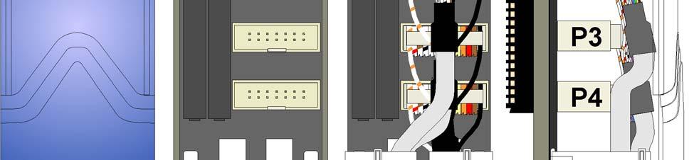

53 Figure 3-4. I/O Module (Remote Termination) Wire Routing Revised Aug-2015 I/O Modules 3-7
54 3.4 Digital Input (DI) Modules Detailed Technical Specifications DI modules provide 16 or 32 digital inputs. Using jumpers, you can individually configure each input as either externally sourced or internally powered using an internal +21Vdc power supply (dry contacts). Note: Early versions of ControlWave DI modules required you to specify either internal or external sourcing for all DIs when you ordered the module; now you can set this yourself using jumpers on a per DI basis. Table 3-1 DI Module General Characteristics Type Number Characteristics Supported Digital Inputs (DI) 16 or 32 Each DI supports/ includes: Nominal input voltage of 24Vdc at 5 ma. Jumper to configure choice of either: externally sourced input - or -internally powered dry contact using internal +21 Vdc power supply. Nominal input current of 5 ma 30 ms input filtering Dedicated LED on module turns ON when DI is ON A DI module consists of a digital input printed circuit board (PCB) with either a terminal block assembly (for local termination) or a header block assembly (for remote termination). Each DI module also includes an LED board, as well as I/O assembly and mounting hardware. The DI PCB connects to the backplane using a 110-pin connector. For detailed technical specifications, please see document CWPAC:DIO available on our website Configurations DI modules (general part number XX-X) come in several different configurations. See Table 3-2 to see the variations. Table 3-2 DI Module Configurations Part Number Number of DIs Termination Connector Local Local : 32 Remote Remote Isolation Surge suppressors and optocouplers electrically isolate the DI field circuitry from the module s bus interface circuitry. Inputs configured 3-8 I/O Modules Revised Aug-2015

55 for use in dry contact applications contain a +21 Vdc isolated power supply powered through an output of the hot swap circuitry which receives power originating on the backplane. Setting Jumpers You must set configuration jumpers for each DI. according to Table 3-3. For a 16DI module, use W1 through W16, for a 32DI module, use W1 through W32. Figure 3-5. DI Module -Right Side View - Jumper Locations Table 3-3. Jumper Assignments: DI Module Jumper Purpose Description WI Configures DI1 Pins 2-3 & 4-5 installed = External Power DI Pins 1-2 & 3-4 installed = Internal Source DI W2-W32 Configures DI2 through DI32 (respectively) Same as W1 Wiring the Module Figure 3-6 shows field wiring assignments associated with locally terminated DI modules; Figure 3-9 shows field wiring assignments associated with remotely terminated DI modules. Figure 3-10 shows an optional remote termination module with built-in discrete relay module that supports input from 120 Vac DIs. The special remote termination module (with built-in discrete relay module) interfaces with an externally sourced DI module. Revised Aug-2015 I/O Modules 3-9


56 Figure 3-6. DI Module - Local Terminal Block Assembly Assignments Figure 3-7. Internally Sourced DI Module - Wiring Diagram Figure 3-8. Externally Powered DI Module - Wiring Diagram 3-10 I/O Modules Revised Aug-2015

 for more information.")
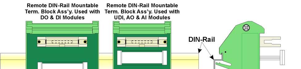
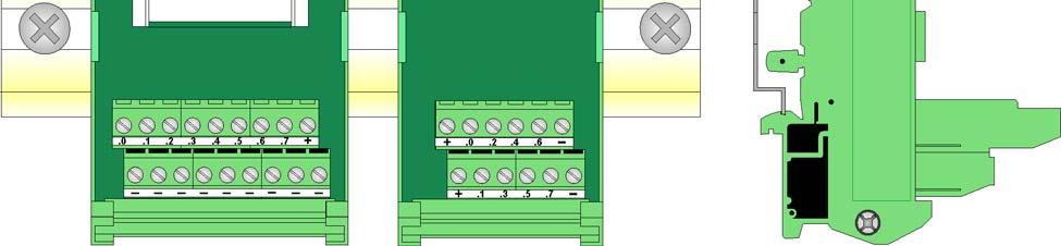
57 FUSES: F0 to F7: 1/8A, F+: 2A Figure 3-9. Remote DIN-Rail Mountable Terminal Block Assembly Assignments Software Configuration To use data from any ControlWave DI module you must add a CW_DI32 board in ControlWave Designer s I/O Configurator, and then configure it. See the ControlWave Designer Programmer's Handbook (D5125) for more information. That same manual includes an I/O Mapping section that describes, for advanced users, the I/O map for this module. Revised Aug-2015 I/O Modules 3-11


58 Figure Remote DIN-Rail Mountable Terminal Block Assembly Assignments for Relay Isolated 120Vac DI Operation 3-12 I/O Modules Revised Aug-2015
59 3.5 Digital Output (DO) Modules DO modules provide 32 or 16 DOs to control signaling functions. DO modules consist of a DO PCB with either a terminal block assembly (for local termination) or a header block assembly (for remote termination). DO modules also include an LED board, a terminal housing assembly, as well as I/O assembly and mounting hardware. Table 3-4 DO Module General Characteristics Type Number Characteristics Supported Digital Outputs (DO) 32 or 16 Each DO supports/ includes: Optically isolated open source MOSFET with surge suppression that is capable of handling 500mA at 31V. Maximum operating frequency of 20 Hz. Dedicated LED on module turns ON when DO is ON. Detailed Technical Specifications For detailed technical specifications, please see document CWPAC:DIO available on our website Configurations The DO module (general part number XX-X) comes in several possible configurations, see Table 3-5: Table 3-5. Isolated DO Module Configurations Part Number Number of DOs Local Local Termination Connector Remote Remote Notes Remote DO with read-back Jumper determines state of DOs on power-up Digital Output with Readback An on-board DO load register stores output data. Jumper JP4 determines the initial state of DOs on power-up. Table 3-6. DO State on Power-up JP4 Jumper Position Initial DO State on Power-Up 1-2 Clear register all outputs set to OFF on power-up, regardless of application initial value setting. 2-3 Hold last output on power-up, DO that was OFF at watchdog is OFF at power-up, DO that was ON at watchdog is ON at power-up. Newer digital output modules with 16 outputs support read-back capability for use in redundant systems. A DO with read-back module Revised Aug-2015 I/O Modules 3-13


60 operating in online mode monitors the DO values of its standby counterpart in order to verify that standby DO values are consistent should a failover occur. Depending upon software configuration settings; a failover can be prevented if they are inconsistent. A standard DO module used in a redundant system does not perform this monitoring; therefore the potential exists to failover to a backup DO module with failed hardware. For critical processes, the redundant DO with read-back capability is recommended. Use the same DO module type in any redundant pair; do not install a DO with read-back module in the primary controller and a standard DO module as its redundant counterpart in the backup controller, or vice versa. See Software Configuration later in this section for details on setting up DO with readback. Wiring the Module Figure 3-11 shows field wiring assignments associated with a locally terminated DO module; Figure 3-12 shows a wiring diagram for the DO. Field wiring assignments associated with remotely terminated DO modules. Figure 3-13 shows field wiring assignments for a remotely terminated DO module. Figure 3-14 shows a special remote termination module with built-in discrete relay modules. Figure Local Terminal Block Assembly Assignments for Open Source Isolated DO Operation 3-14 I/O Modules Revised Aug-2015
61 Figure Open Source Isolated DO Module - Wiring Diagram Revised Aug-2015 I/O Modules 3-15


62 FUSES: F0 to F7: 1A, F+: 2A Figure Remote DIN-Rail Mountable Terminal Block Assembly Assignments for Open Source Isolated DO Operation 3-16 I/O Modules Revised Aug-2015


63 Figure Remote DIN-Rail Mountable Terminal Block Assembly Assignments for Relay Isolated 24Vdc DO Operation Software Configuration To use data from any ControlWave DO module you must add a CW_DO32 board in ControlWave Designer s I/O Configurator, and then configure it. See the ControlWave Designer Programmer's Revised Aug-2015 I/O Modules 3-17
64 Handbook (D5125) for more information. That same manual includes an I/O Mapping section that describes, for advanced users, the I/O map for this module. DO with Readback in a Redundant System Variables in the ControlWave project govern how inconsistencies between the online DO module and the standby DO module are handled in redundant systems with DO readback. Information on configuring system variables is included in the ControlWave Designer Programmer s Handbook (D5125). If there is a discrepancy between the value of the online and standby DOs, the system sets a status variable to TRUE. For local I/O boards, this is a system variable that follows the format: _RDN_IO_n_ERR where n is the I/O slot number of the DO module in the backup unit that has a failure. For boards residing in an I/O expansion rack, instead of a system variable, a variable mapped by the _ER_STAT virtual status board provides this indication. By default, the name of the variable follows one of two possible formats. ERSTAT_n_RDN_IO_x_ERR ERST_n_RDN_IO_x_ERR where n is the I/O slot number of the virtual ER_STAT board, and x is the I/O slot number of the digital output module. See the I/O Configurator and I/O Mapping sections of the ControlWave Designer Programmer's Handbook (D5125) for more information. You can optionally rename these variables. You should configure these variables as alarms so you receive notification of a failure of the backup DO module. See the ControlWave Designer online help for information on alarm configuration. When a read-back failure occurs, the FAIL LED remains RED until the unit reboots, either through a sideload, forced redundant switchover, or power-down and restart, or you remove and replace the board (hot card replacement). Each of these operations momentarily turns the FAIL LED to GREEN (and the associated _ERR error variable to FALSE) until a new readback failure occurs, which changes the LED back to RED, and the associated _ERR error variable back to TRUE. For boards installed locally in the controller (local I/O), another system variable (_RDN_IOERR_WARN) determines whether a failure of the standby DO (as indicated by the LED and associated _ERR error variable) should only be treated as a warning condition, which would still allow a failover to occur, or as an error which would prevent a 3-18 I/O Modules Revised Aug-2015
65 failover to the standby. When you set this system variable to FALSE, the system treats a DO readback failure in the associated device as an error; failover is inhibited. When you set this variable to TRUE, the system treats a DO readback failure in the associated device as a warning that does not prevent a failover, and the only reporting is via the _RDN_IO_x_ERR system variables and LEDs discussed, above. For boards residing in an I/O expansion rack, instead of a system variable for this purpose, you must map a variable from the _ER_STAT virtual status board named either ERSTAT_RDN_IOERR_WARN (or ERST_RDN_IOERR_WARN). NOTE: Those are the default names, you can change them as needed. Note: In the I/O Configurator, you must associate these boards with a cyclic task, and the task must not run faster than 10 milliseconds. Revised Aug-2015 I/O Modules 3-19
66 3.6 Analog Input (AI) Modules AI modules support either 16 or eight 4 20 ma or 1 5 Vdc analog inputs. AI modules consist of an AI PCB with either a terminal block assembly (for local termination) or a header block assembly (for remote termination). AI modules also include an LED board, a terminal housing assembly, as well as I/O assembly and mounting hardware. Table 3-7 Analog Input (AI) Module General Characteristics Type Analog Inputs (AI) Number Supported Characteristics 16 or 8 Each AI supports: Either 4 20mA internally sourced input or 1 5Vdc isolated input operation. Choice for whether the module supports 4-20mA or 1-5Vdc is set at the factory. 1-5Vdc AIs have a common mode range of 31Vdc. 4-20mA inputs reference VFxx of the module. Analog input circuitry isolated from bus interface. Surge suppression and signal conditioning. Cable Shields Connect cable shields associated with AI wiring to the ControlWave housing ground. Multiple shield terminations require that you supply a copper ground bus (up to a #4 AWG wire size) and connect it to the housing s ground lug. This ground bus must accommodate a connection to a known good earth ground (in lieu of a direct connection from the ground lug) and to all AI cable shields. Shield wires should use an appropriate terminal lug. Secure them to the copper bus using industry rugged hardware (screw/bolt, lock washer, and nuts). Detailed Technical Specifications For detailed technical specifications, please see document CWPAC:AIO available on our website Configurations The AI module (general part number XX-X) has the following configurations: 3-20 I/O Modules Revised Aug-2015
67 Table 3-8 Analog Input Module Configurations Part Number Number of AIs Termination Connector Notes Local 4-20 ma Local 4-20 ma Remote 4-20 ma Remote 4-20 ma Remote 1-5 Vdc Wiring the Module Figure 3-18 shows terminal assignments for a locally terminated AI module; Figure 3-19 and Figure 3-20 show terminal assignments for a 4-20mA and a 1-5Vdc remotely terminated AI, respectively. Figure Internally Sourced 4-20mA Current Loop AI - Wiring Diagram Figure Externally Powered 4-20mA Current Loop AI - Wiring Diagram Revised Aug-2015 I/O Modules 3-21

 for more information.")
68 Figure Externally Powered Isolated 1-5 Volt AI - Wiring Diagram Figure Local AI Module Terminal Blocks Assembly Assignments Software Configuration To use data from any ControlWave analog input module you must add a CW_AI16 board in ControlWave Designer s I/O Configurator, and then configure it. See the ControlWave Designer Programmer's Handbook (D5125) for more information. That same manual includes an I/O Mapping section that describes, for advanced users, the I/O map for this module I/O Modules Revised Aug-2015


69 FUSES: F0, F2, F4, F6: 1/8A Figure Remote DIN-Rail Mountable Terminal Block Assembly Assignments for 4-20 ma AI Operation Revised Aug-2015 I/O Modules 3-23


70 FUSES: F0, F2, F4, F6: 1/8A Figure Remote DIN-Rail Mountable Terminal Block Assembly Assignments for 1-5V AI Operation 3-24 I/O Modules Revised Aug-2015
71 3.7 Analog Output (AO) Modules AO modules support eight 4 20 ma analog outputs. AO modules consist of an AO PCB (with a daughter board when configured for readback) an LED board, a terminal housing assembly, as well as I/O assembly and mounting hardware. Table 3-9 Analog Output (AO) Module General Characteristics Type Analog Outputs (AO) Number Supported Characteristics 8 Each AO supports: 4 20mA output with a maximum external load of 650 ohms. Analog output circuitry isolated from bus interface Surge suppression Analog Output with Read-back Analog output modules with eight outputs are available in two versions standard AO, or AO with read-back capability for use in redundant systems. Both versions may be used in redundant systems; however, they operate differently. An AO with read-back module operating in online mode monitors the AO values of its standby counterpart in order to verify that standby AO values are consistent should a failover occur. Depending upon software configuration settings; a failover can be prevented if they are inconsistent. A standard AO module used in a redundant system does not perform this monitoring; therefore the potential exists to failover to a backup AO module with failed hardware. For critical processes, the redundant AO with read-back capability is recommended. Use the same AO module type in any redundant pair i.e. do not install an AO with read-back module in the primary controller and a standard AO module as its redundant counterpart in the backup controller, or vice versa. See Software Configuration later in this section for details on setting up AO with readback. Detailed Technical Specifications For detailed technical specifications, please see document CWPAC:AIO available on our website Configurations The isolated AO module (general part number XX-X) has the following configurations: Revised Aug-2015 I/O Modules 3-25


72 Table Analog Output Module Configurations Part Number Number of AOs Termination Connector Notes local 4-20mA remote 4-20mA remote 4-20mA AO Readback on this module Wiring the Module Figure 3-21 shows field wiring assignments for a locally terminated AO module. Figure 3-22 shows field wiring assignments for a remotely terminated AO module. Figure Local AO Module Terminal Blocks Assembly Assignments 3-26 I/O Modules Revised Aug-2015
73 FUSES: F0, F2, F4, F6: 1/8A Figure Remote DIN-Rail Mountable Terminal Block Assembly Assignments for AO 4-20mA Operation Revised Aug-2015 I/O Modules 3-27
74 Figure mA Current Loop AO - Wiring Diagrams Software Configuration To use data from any ControlWave analog output module you must add a CW_AO8 board in ControlWave Designer s I/O Configurator, and then configure it. See the ControlWave Designer Programmer's Handbook (D5125) for more information. That same manual includes an I/O Mapping section that describes, for advanced users, the I/O map for this module. AO with Readback in a Redundant System Variables in the ControlWave project govern how inconsistencies between the online AO module and the standby AO module are handled in redundant systems with AO readback. Information on configuring system variables is included in the ControlWave Designer Programmer s Handbook (D5125). If there is a difference of more than 0.5% (of span) between the value of the online and standby AO values, a variable will be set TRUE. For local I/O boards, this is a system variable that follows the format: _RDN_IO_n_ERR where n is the I/O slot number of the AO module. For boards residing in an I/O expansion rack, instead of a system variable, this indication is provided by a variable mapped by the _ER_STAT virtual status board. By default, the name of the variable follows one of two possible formats. ERSTAT_n_RDN_IO_x_ERR ERST_n_RDN_IO_x_ERR where n is the I/O slot number of the virtual ER_STAT board, and x is the I/O slot number of the analog output module. See the I/O Configurator and I/O Mapping sections of the ControlWave Designer 3-28 I/O Modules Revised Aug-2015
75 Programmer's Handbook (D5125) for more information. You can optionally rename these variables. You should configure these variables as alarms so you receive notification of a failure of the backup AO module. See the ControlWave Designer online help for information on alarm configuration. When a read-back failure occurs, the FAIL LED remains RED until the unit is rebooted, either through a sideload, forced redundant switchover, or power-down and restart, or you remove and replace the board (hot card replacement). Each of these operations momentarily turns the FAIL LED to GREEN (and the associated _ERR error variable to FALSE) until a new readback failure occurs, which will change the LED back to RED, and the associated _ERR error variable back to TRUE. For boards installed locally in the controller (local I/O) another system variable (_RDN_IOERR_WARN) determines whether a failure of the standby AO (as indicated by the LED and associated _ERR error variable) should only be treated as a warning condition, which would still allow a failover to occur, or as an error which would prevent a failover to the standby. When you set this system variable to FALSE, an AO readback failure in the associated device is treated as an error; failover is inhibited. When you set this variable to TRUE, an AO readback failure in the associated device is treated as a warning that does not prevent a failover, and the only reporting is via the _RDN_IO_x_ERR system variables and LEDs discussed, above. For boards residing in an I/O expansion rack, instead of a system variable for this purpose, you must have mapped a variable from the _ER_STAT virtual status board named either ERSTAT_RDN_IOERR_WARN (or ERST_RDN_IOERR_WARN). NOTE: Those are the default names, you can change them as needed. Note: In the I/O Configurator, you must associate these boards with a cyclic task, and the task must not run faster than 10 milliseconds. Revised Aug-2015 I/O Modules 3-29
76 3.8 Universal Digital Input (UDI) Modules Universal Digital Input (UDI) modules include six inputs which you can individually configure as high speed counters or polled inputs. UDI modules consist of a UDI PCB, either a terminal board assembly for local termination or a header block assembly for remote termination, a terminal housing assembly, an LED board, as well as I/O assembly and mounting hardware. Note: Because UDI modules are interrupt driven, you can only install them in the first four I/O slots. Table UDI Module General Characteristics Type Universal Digital Inputs (UDI) Number Supported Characteristics 6 Each UDI supports/includes: Field input can be a driven signal, an open collector output, or a relay contact. Inputs handle 24V Jumper to configure point for debounce enable or debounce disable. Software configures point as a polled input with a 30 millisecond filter or as a 16-bit high speed counter (totalizer) with a 20 microsecond filter. Maximum input frequency of 10 KHz with a nominal input current of 5mA. 16 bit counter. Signal conditioning circuitry and bandwidth limiting circuitry. Software selectable delays for signal conditioning. Each input is optically isolated from the field device. Each input has an electrical isolation of 500Vdc to chassis and 1500Vdc to system logic. Surge protection. Protection from a 31dc transorb (across input and to field common) that meets ANSI/IEEE standard C Additional Technical Specifications For additional technical specifications, please see document CWPAC:UDI available on our website I/O Modules Revised Aug-2015
77 Configurations The UDI module (general part number XX-X) has the following configurations: Table UDI Module Configurations Part Number Number of UDIs Termination Connector local remote Setting Jumpers Each input has a jumper to enable/disable debounce. Enabling debounce activates filters that reduce spurious pulses caused by relay contact bounce. Figure 3-24 shows the location of jumpers on the module Jumper locations W5 W6 W7 W8 1 1 W1 W2 W3 W4 1 W12 W11 1 W9 W10 1 Front Terminal Housing Ass y. Right Side Figure UDI Module -Right Side View -Jumper Locations Revised Aug-2015 I/O Modules 3-31
78 Table Jumper Assignments: UDI Module Jumper Purpose Description W1 Configures UDI1 Pins 1-2 installed = Enable Debounce (Factory default). A change of state on both the SET and RST (reset) field inputs is required to accumulate counts. Pins 2-3 installed = Disable Debounce. A change of state on the SET field input is required to accumulate counts. W2 through W6 Configures UDI 2 through UDI6 Pins 1-2 installed = Enable Debounce (Factory default). A change of state on both the SET and RST (reset) field inputs is required to accumulate counts. Pins 2-3 installed = Disable Debounce. A change of state on the SET field input is required to accumulate counts. Wiring the Module Figure 3-27 shows field wiring assignments for the locally terminated UDI module. It also includes examples for relay contact and open collector applications. Figure 3-28 shows field wiring assignments for the remotely terminated UDI module. Figure UDI (Debounce Enabled) Wiring Diagram Figure UDI (Debounce Disabled) Wiring Diagram 3-32 I/O Modules Revised Aug-2015
79 Terminal Block Assembly Assignments for UDI Operation +HSCSET1 HSCCOM1 +HSCRST1 +HSCSET3 HSCCOM3 +HSCRST3 +HSCSET5 HSCCOM5 +HSCRST5 +HSCSET2 HSCCOM2 +HSCRST2 +HSCSET4 HSCCOM4 +HSCRST4 +HSCSET6 HSCCOM6 +HSCRST6 FIELD CIRCUITRY Relay Contact FIELD CIRCUITRY Open Collector or Relay Contact HSCSET 1 HSCCOM 3 HSCRST 5 A HSCSET 1 HSCCOM 3 B Field TB Field TB Figure Local UDI Terminal Block/Configuration Diagram Revised Aug-2015 I/O Modules 3-33
80 Cable Assembly (One of 2 Cables) End of cable that interfaces with Remote UDI Module s Header Block Assembly End of cable that interfaces with Remote UDI Module s DIN-Rail Mountable Terminal Block Assembly From P1 From P2 UDI1 - UDI3 UDI4 - UDI6 FUSE F2 FUSE F6 FUSE F0 FUSE F /24V UDI (without fuses) A = Top TB + = N/A.0 = UDISET1.2 = UDIRST1.4 = UDICOM2.6 = UDISET3 _ = UDIRST3 B = Bottom TB + = N/A.1 = UDICOM1.3 = UDISET2.5 = UDIRST2.7 = UDICOM3 _ = UDIRST3 12/24V UDI (with fuses) A = Top TB + = N/A 0 = UDISET4 2 = UDIRST4 4 = UDICOM5 6 = UDISET6 + = N/A B = Bottom TB _ = UDIRST6 1 = UDICOM4 3 = UDISET5 5 = UDIRST5 7 = UDICOM6 _ = UDIRST6 FUSES: F0, F2, F4, F6: 1/8A Figure Remote DIN-Rail Mountable Terminal Block Assembly Assignments for UDI Operation 3-34 I/O Modules Revised Aug-2015

81 Software Configuration To use data from a UDI module you must add a CW_HSC12 board in ControlWave Designer s I/O Configurator, and then configure it. The I/O Configurator is where you specify the usage for each input using the Select Filter list box. Figure Selecting Input Type in ControlWave Designer I/O Configurator Choose one of the following: HSC Channel to select a 20 microsecond delay for 10 khz high speed counter applications. 1 MS to select a 1 millisecond delay for a low speed counter application. 30 MS to select a 30 millisecond delay for a polled input. This is for general purpose inputs or contacts where contact bounce may apply. See the ControlWave Designer Programmer's Handbook (D5125) for more information. That same manual includes an I/O Mapping section that describes, for advanced users, the I/O map for this module. Revised Aug-2015 I/O Modules 3-35
82 3.9 Isolated Resistance Temperature Device (RTD) Input Module RTD Input modules provide a total of four inputs. Firmware detects the RTD type (2-, 3- or 4 wire) via the installation of jumper wires on the terminal block for 2-wire and 3-wire RTDs (see Figure 3-30). Table Isolated RTD Input Module General Characteristics Type Number Supported Characteristics Isolated RTD Input 4 Each isolated RTD input supports/includes: Signal conditioning circuitry Surge protection with a 25V transorb that meets IEEE standard Current limiting for over voltage protection 24-bit analog to digital converter (ADC) Common mode range of 500V with respect to chassis Electrical isolation of 500Vdc (channel to channel/system bus) Source current to RTD limited to 330 ua Detailed Technical Specifications The RTD Input Module consists of an isolated RTD input board, a terminal board assembly (for local termination) or a header block assembly (for remote termination), an LED board, a terminal housing assembly, as well as I/O assembly and mounting hardware. For additional technical specifications, please see document CWPAC:TEMP available on our website Configuration The isolated RTD module (general part number XX-X) has the following configurations Table Isolated RTD Input Module Configurations Part Number Termination Connector Notes local remote Enabling/Disabling LEDs using jumper The Isolated RTD Module includes a jumper (W1) to enable/disable LEDs on the module. Normally, you should keep the LEDs enabled, but if power conservation is an issue, you could disable the LEDs I/O Modules Revised Aug-2015

83 Table Jumper Assignments: Non-isolated HSC Module Jumper Purpose Description W1 Enables/disables LEDs on Pins 1-2 installed = Enable LEDs (Factory default). module Pins 2-3 installed = Disable LEDs Wiring the Module Figure 3-31 shows field wiring assignments for locally terminated isolated RTD modules. Figure 3-32 shows field wiring assignments for remotely terminated isolated RTD modules. Figure 3-30 provides wiring diagrams for 2-wire, 3-wire, and 4-wire RTDs to the local RTD module terminal blocks; wiring assignments, such as +RTD#_3/4W, -RTD#_4W, +RTD# and RTD# are similar to those assigned to the Remote DIN-rail mountable terminal blocks. Note: To maintain specified accuracy with a 3-wire RTD, you must match the two field wires that source and sink the RTD current within 0.01 ohms (matched in length and matched in wire type) and the ambient temperature on these wires must be the same. Figure Isolated RTD Module - 2-Wire, 3-Wire & 4-Wire Wiring Diagram Revised Aug-2015 I/O Modules 3-37


84 Figure Local Isolated RTD Module Terminal Block Assembly Assignments Software Configuration To use data from an Isolated RTD Input module you must add a CWM_RTD8 board in ControlWave Designer s I/O Configurator, and then configure it. See the ControlWave Designer Programmer's Handbook (D5125) for more information. That same manual includes an I/O Mapping section that describes, for advanced users, the I/O map for this module I/O Modules Revised Aug-2015


85 Figure Remote DIN-Rail Mountable Terminal Block Assembly Assignments for Isolated RTD Module Operation Revised Aug-2015 I/O Modules 3-39
86 3.10 Isolated Thermocouple Module Thermocouple modules (sometimes known as low level analog inputs) provide six individually isolated differential inputs for thermocouples or 10mV inputs plus one cold junction compensation (CJC) input for temperature compensation at the terminal block. Table Isolated Thermocouple Module General Characteristics Type Number Supported Characteristics Thermocouple (TC) 6 Each isolated thermocouple supports/includes: Signal conditioning circuitry including a 2.5V reference Surge suppression with a 188V Transorb that meets IEEE standard Over voltage protection Common mode range for each channel is 500Vdc with respect to chassis. 24-bit analog to digital converter (ADC) Detailed Technical Specifications For additional technical specifications, please see document CWPAC:TEMP available on our website Configuration The isolated thermocouple module (general part number XX- X) has the following configurations: Table Isolated Thermocouple Module Configurations Part Number Termination Connector Notes local remote Enabling/Disabling LEDs using jumper The Isolated Thermocouple Module includes a jumper (W2) to enable/disable LEDs on the module. Normally, you should keep the LEDs enabled, but if power conservation is an issue, you could disable the LEDs. Table Jumper Assignments: Isolated Thermocouple Module Jumper Purpose Description W2 Enables/disables LEDs on Pins 1-2 installed = Enable LEDs (Factory default). module Pins 2-3 installed = Disable LEDs 3-40 I/O Modules Revised Aug-2015
 with a built-in RTD provides thermocouple temperature compensation at the terminal block and is electrically isolated.")
87 Wiring the Module Figure 3-34 shows field wiring for locally terminated isolated thermocouple modules. Figure 3-35 shows field wiring for remotely terminated isolated thermocouple modules. The cold junction compensation (CJC) with a built-in RTD provides thermocouple temperature compensation at the terminal block and is electrically isolated. Pins 8, 9 and 10 of the local terminal block source and sink the CJC s RTD. Figure 3-35 also provides diagrams showing the wiring for thermocouples and the 3-wire RTDs to a locally terminated TC module. Wiring assignments (that is, +AI#, -AI#, +CJC (Sense), -CJC (Return) & +CJC (Reference) are similar to those assigned to the remote DINrail mountable terminal blocks. A small CJC PCB is factory-installed to the terminal block. Figure Isolated Thermocouple Module - Wiring Diagram Revised Aug-2015 I/O Modules 3-41


88 Figure Local Isolated Thermocouple Module Terminal Block Assembly Assignments 3-42 I/O Modules Revised Aug-2015


89 Figure Remote DIN-Rail Mountable Terminal Block Assembly Assignments for Isolated Thermocouple Module Operation Revised Aug-2015 I/O Modules 3-43
90 Ranges & Errors Table 3-20 provides the accuracy, resolution and temperature range for the various thermocouples and 10mV LLAI inputs. Table 3-21 lists the RTD error with the CJC. Table Thermocouple Module Input Accuracy and Resolution Input Type Accuracy/Range Resolution 25 C 20 C to +70 C B Thermocouple 100 C to 200 C 200 C to 390 C 390 C to 840 C 840 C to 1820 C 2.00 C 1.00 C 0.50 C 0.20 C 8 C 4 C 2 C 1 C 16 C 8 C 4 C 2 C R Thermocouple S Thermocouple 50 C to +50 C +50 C to 1720 C 50 C to +50 C +50 C to 1760 C 0.40 C 0.17 C 0.37 C 0.18 C 2 C 1 C 2 C 1 C 4 C 2 C 4 C 2 C C Thermocouple 0 C to 2315 C 0.16 C 0.75 C 1.5 C N Thermocouple J Thermocouple E Thermocouple K Thermocouple T Thermocouple 270 C to 260 C 260 C to 250 C 250 C to 230 C 230 C to 150 C 150 C to 1300 C 210 C to 191 C 190 C to 1200 C 270 C to 260 C 260 C to 225 C 225 C to 200 C 200 C to 1000 C 270 C to 261 C 260 C to 246 C 245 C to 180 C 179 C to 145 C 145 C to 1372 C 270 C to 261 C 260 C to 251 C 250 C to 181 C 180 C to 136 C 135 C to 400 C 1.50 C 0.75 C 0.50 C 0.25 C 0.09 C 0.08 C 0.11 C 1.00 C 0.25 C 0.08 C 0.09 C 2.00 C 0.56 C 0.25 C 0.08 C 0.14 C 1.50 C 0.38 C 0.18 C 0.08 C 0.06 C 8 C 4 C 2 C 1 C C C C 3 C 1 C C C 5 C 2 C 1 C C C 4 C 2 C 1 C C C 10 C 8 C 4 C 2 C 1 C 1.5 C 1 C 6 C 2 C 1.5 C 1 C 10 C 4 C 2 C 1.5 C 1 C 8 C 4 C 2 C 1.5 C 1 C 10mV 10mV 1.2 V 0.25% 0.05% Note: The CJC RTD adds an additional error (see Table 3-21) Table TC Module RTD Error with CJC at 25 C Thermocouple Type Process Temperature Range RTD Error with 25 C B 100 C to 1820 C 0.30 C R S 50 C to +50 C +50 C to 1720 C 50 C to +50 C +50 C to 1760 C 0.49 C 0.30 C 0.45 C 0.30 C 3-44 I/O Modules Revised Aug-2015
91 Thermocouple Type Process Temperature Range RTD Error with 25 C C 0 C to 2315 C 0.30 C N J E K T 270 C to 261 C 260 C to 251 C 250 C to 231 C 230 C to 189 C 188 C to 70 C 70 C to + 25 C +25 C to 1300 C 210 C to 111 C 110 C to +25 C +25 C to 1200 C 270 C to 261 C 260 C to 245 C 244 C to 200 C 200 C to 87 C 86 C to +25 C +25 C to 100 C 270 C to 261 C 260 C to 247 C 246 C to 222 C 220 C to 160 C 159 C to +25 C +25 C to 1372 C 270 C to 261 C 260 C to 243 C 242 C to 196 C 195 C to 61 C 60 C to +25 C +25 C to 400 C C 5.00 C 2.70 C 1.40 C 0.70 C 0.35 C 0.30 C 0.80 C 0.40 C 0.30 C 10 C 3 C 1.50 C 0.75 C 0.39 C 0.30 C C 4.50 C 2.20 C 1.10 C 0.55 C 0.30 C C 3.00 C 1.50 C 0.75 C C 0.30 C Note: Use straight-line approximation to calculate approximate error between end points. Software Configuration To use data from an Isolated Thermocouple module you must add a CW_TC12 board in ControlWave Designer s I/O Configurator, and then configure it. See the ControlWave Designer Programmer's Handbook (D5125) for more information. That same manual includes an I/O Mapping section that describes, for advanced users, the I/O map for this module. Revised Aug-2015 I/O Modules 3-45
92 This page is intentionally left blank

93 Chapter 4 Operation In This Chapter This chapter provides general operational details for using the ControlWave. 4.1 Powering Up/Powering Down the ControlWave Communicating with the ControlWave Default Comm Port Settings Changing Port Settings Collecting Data from the ControlWave Creating and Downloading an Application (ControlWave Project) Creating and Maintaining Backups Creating a Zipped Project File (*.ZWT) For Backup Saving Flash Configuration Parameters (*.FCP) Backing up Data Powering Up/Powering Down the ControlWave Open the bezel door on the PSSM and position the power switch (or switches if you have dual supplies) to the OFF (down) position to turn the ControlWave OFF or to the ON (up) position to turn it ON. ON position (up) to turn ON the power supply OFF position (down) to turn OFF the power supply Figure 4-1. Power Switches on PSSM Setting the Operating Mode (Run/Remote/Local Switch) Run/Remote/ Local Switch You set the CPU s Run/Remote/Local switch using a removable key. You can remove this key when the switch is in any position to prevent an unauthorized person from changing the operating mode. Figure 4-2. Run/Remote/Local Key Switch Run prevents you from performing any ControlWave Designer debug or program functions (start/stop, application downloads, etc.). Remote Revised Aug-2015 Operation 4-1
94 and Local functions depend on how you configured the communication port in ControlWave Designer (serial, IP, or OpenBSI). IP/OpenBSI (BSAP): If you configure the communication port for either of these choices in ControlWave Designer it becomes a remote port: set the Run/Remote/Local switch to Remote for downloads. Serial: If you configure the communication port for serial in ControlWave Designer, it becomes a local port: set the Run/Remote/Local switch to Local for downloads. Note: Setting the Run/Remote/Local switch to Local enables communications through any comm port. However, if you set the switch to Remote, that restricts communications only to comm ports configured as remote comm ports. 4.2 Communicating with the ControlWave You communicate to the ControlWave by connecting a cable between a port on your PC workstation and one of the ControlWave ports. See Section 2.4 for more information on communications. The port at the PC workstation must match the configuration of the ControlWave port Default Comm Port Settings As delivered from the factory, ControlWave communication ports have default settings. Table 4-1 details these defaults. Table 4-1. Default Comm Port Settings (by PCB) Port PCB Default Configuration COM1 CPU Ships from factory at RS-232; Kbps using BSAP. Once the default switch is OFF, a factory default of IP Point-to-Point protocol (PPP) at 115,200 applies with an IP address of and a mask of COM2 CPU RS-232; 9600 baud, 8 bits, no parity, 1 stop bit, BSAP or ControlWave Designer protocol COM3 SCB RS-485; 9600 baud, 8 bits, no parity, 1 stop bit, BSAP or ControlWave Designer protocol COM4 SCB RS-232 or RS-485 depending upon factory order; 9600 baud, 8 bits, no parity, 1 stop bit, BSAP or ControlWave Designer protocol Note: You can re-enable the factory comm settings at any time by setting switch 3 on the CPU module s SW1 to OFF. 4-2 Operation Revised Aug-2015
95 Ethernet The ControlWave can include from one to three Ethernet ports. You can connect directly or through a network to a PC equipped with an Ethernet port. The default IP addresses and masks for these are: ETH1 IP Address: IP Mask: ETH2 IP Address: IP Mask: ETH3 IP Address: IP Mask: Changing Port Settings You change port settings (baud rate, port type, IP address, and so on) using the Flash Configuration utility. You must establish communications with the ControlWave using NetView, LocalView, or TechView before you can run the Flash Configuration utility. Note: For detailed information on using the Flash Configuration utility, see Chapter 5 of the OpenBSI Utilities Manual (D5081). Caution When you change the baud rate for a port, the baud rate changes as soon as you write the flash file changes to the RTU, and do not require a reset. For this reason, you should not change baud rate for the active port on which you are communicating, or communications will immediately stop due to the baud rate mismatch between the PC port and the controller port. If this happens accidentally, you can use CPU switch settings as discussed in the notes in Section to restore defaults and re-establish communications. Revised Aug-2015 Operation 4-3
96 4.2.3 Collecting Data from the ControlWave OpenBSI utilities such as DataView, Data Array Save/Restore and Harvester allow you to collect real time data (values of variables, array values, alarm messages) and historical data (audit records, archive files) from the ControlWave. See the OpenBSI Utilities Manual (D5081) for details. SCADA software such as OpenEnterprise can then present this data to an operator in the form of graphical displays and reports. 4.3 Creating and Downloading an Application (ControlWave Project) Your ControlWave executes an application called a ControlWave project. You create the project using PC-based ControlWave Designer software. Instructions for creating a ControlWave project are beyond the scope of this manual. Please refer to the following sources for information: Getting Started with ControlWave Designer (D5085) ControlWave Quick Setup Guide (D5084) ControlWave Designer Programmer s Handbook (D5125) ControlWave Designer online help You must connect the ControlWave to a PC running ControlWave Designer software and OpenBSI software. Note: You can download an application either from ControlWave Designer or from the OpenBSI 1131 Downloader. 1. Set the CPU s Run/Remote/Local (key-operated) switch: If the PC is connected to a comm port configured as an IP or OpenBSI Network port set the CPU s Run/Remote/Local switch to Remote If the PC is connected to a comm port configured as a serial port set the CPU s Run/Remote/Local switch to Local Note: COM1 has a factory default of Kps (RS-232) using the Internet Point-to-Point Protocol (PPP). Do not connect COM1 to a PC unless you configure that PC s RS-232 port for PPP. 2. Define the project, setting communication and configuration parameters. 3. Download the project according to instructions in the Downloading section of the ControlWave Designer Programmer's Manual (D5125). 4. After the download completes successfully, restore the PSSM switch settings: Turn Run/Remote/Local to Run 4-4 Operation Revised Aug-2015
97 4.4 Creating and Maintaining Backups You should always maintain a current backup of each ControlWave project and keep it in a safe place, preferably in a location physically separate from the controller. The reason we recommend you keep a backup files is that if a disaster occurs that damages or destroys your ControlWave hardware (flood, lightning strike, etc.) you don t want to also lose its control strategy software programs. Otherwise, when the unit is repaired or replaced, you d have to create a new ControlWave project from scratch, which might take a lot longer than replacing a few damaged modules. Caution Always maintain a backup copy of your ControlWave project in a safe place. Anytime you modify your ControlWave project, be sure to create a new backup of the new project. Notes: You may find it useful to maintain more than one backup copy in case the backup media itself fails, for example, a CD-ROM becomes unreadable because it melted in the sun or a thumb drive fails because someone spilled coffee on it. If you don t keep more than one backup copy, it s a good idea to periodically test your backup copy to verify that the media has not failed Creating a Zipped Project File (*.ZWT) For Backup Note: The.zwt file is a complete backup of your entire project including code, comments and graphics. It may be stored on your PC or removable storage media. It may also be downloaded and archived to ControlWave Flash memory where it may be uploaded at a later time for editing. With your current ControlWave project open in ControlWave Designer, perform the following steps: 1. Click File > Save Project As / Zip Project As. Revised Aug-2015 Operation 4-5
. 4. In the Zip Options area, select which additional files you want to include in the zwt file.")
98 Figure 4-3. Saving a Backup of Your Project 2. In the Save/Zip project as dialog box, specify a project name in the File name field. In Figure 4-3 we chose the name mynewproj. 3. In the Save as type field, choose Zipped Project Files (*.zwt). 4. In the Zip Options area, select which additional files you want to include in the zwt file. Other than increasing the file size of the zwt, it doesn t hurt to check any or all of these options. Zip Option Zip User-Libraries Zip Frontend-Code Zip FW-Libraries Zip Pagelayouts Description If you created your own user-defined functions or function blocks, you must select this to preserve them. If you selected Zip User-Libraries you should also select this option to include compiled code for libraries in your zip file. Otherwise, you need to re-compile your user libraries with the project when you unzip the zwt. This includes firmware libraries, such as ACCOL3.FWL in your zwt. This includes pagelayout information for printing your project, as well as graphical elements used in certain 1131 languages. 5. Click Zip and a progress bar displays the percent complete of the zipping process. 4-6 Operation Revised Aug-2015
99 6. When the zip process completes, you ll see a message box reporting successful completion. Click OK. 7. Copy the resulting zwt file to backup media (CD-ROM, thumb drive, etc.) If you ever need to restore the project, just open the zwt file in ControlWave Designer, load libraries as needed, then compile the project and download it into the ControlWave Saving Flash Configuration Parameters (*.FCP) You must establish communications with the ControlWave using NetView, LocalView, or TechView before you can run the Flash Configuration utility. Note: For detailed information on using the Flash Configuration utility, see Chapter 5 of the OpenBSI Utilities Manual (D5081). 1. Start the Flash Configuration utility. To do this in NetView or LocalView, right-click on the icon for this ControlWave and choose RTU > RTU Configuration Parameters. To do this in TechView, click Operations > Access Flash Parameters or click the Access Flash icon. 2. Depending upon how your system is configured, the Flash Configuration Loading Options dialog box may open. If it does, choose Load from device and wait for the utility to Revised Aug-2015 Operation 4-7
100 retrieve all parameters from the ControlWave, then skip to step 4, otherwise, just proceed to step Click and wait for the utility to retrieve all parameters from the ControlWave. 4. Click and specify a name for your FCP file, then click Save. When the status line indicates successful completion, your FCP file in done. 5. Copy the resulting FCP file to backup media (CD-ROM, thumb drive, etc.) If you ever need to restore the FCP parameters to the controller, establish communications with the unit, start the Flash Configuration utility, and load the FCP file using the Read from FCP button, then choose the Write to RTU button Backing up Data You can back up certain types of data and restore it if needed. There are other types of data that you can only collect, but you cannot restore. If you have certain variables that represent tuning parameters (setpoints, for example) you can use tools such as the OpenBSI DataView recipe feature to save those values to a recipe file on the PC, and then restore them at a later time. See Chapter 8 of the OpenBSI Utilities Manual (D5081). You can store the contents of read/write data arrays using the OpenBSI Data Array Save/Restore utility. See Chapter 13 of the OpenBSI Utilities Manual (D5081). You can collect alarms, and historical data (audit records, archive files) but you cannot restore alarms or historical data. 4-8 Operation Revised Aug-2015
101 Chapter 5 Service and Troubleshooting ControlWave Instruction Manual In This Chapter This chapter provides general diagnostic and test information for the ControlWave. 5.1 Upgrading Firmware Removing or Replacing Components Accessing Modules for Testing Removing/Replacing the Bezel Removing/Replacing the CPU Module Removing/Replacing the PSSM Removing/Replacing an I/O Module (Hot Swapping) Removing/Replacing the Backup Battery General Troubleshooting Procedures Common Communication Configuration Problems Checking LEDs Checking Wiring/Signals Port 80 Display Codes Reset Switch WINDIAG Diagnostic Utility Available Diagnostics Core Updump Equipment You need the following equipment to perform the procedures described in this chapter: To run diagnostics software: PC with WINDIAG software, and either OpenBSI LocalView, NetView, or TechView for communications. Null modem interface cable Loop-back plug for RS-232 port (see Figure 5-21) Loop-back plug for RS-485 port (see Figure 5-22) Loop-back plug, 8-pin RJ-45 male (for twisted pair Ethernet) (see Figure 5-24) To perform firmware upgrades: Null modem interface cable PC with the following software: o OpenBSI System Firmware Downloader and either NetView, LocalView, or TechView for communications. o HyperTerminal (included in Windows XP) Note: When you service a ControlWave on site, we recommend that you close down (or place under manual control) any associated processes. This precaution prevents any processes from accidentally running out of control when you conduct tests. Revised Aug-2015 Service & Troubleshooting 5-1
102 Caution Harmful electrical potentials may still exist at the field wiring terminals even though the ControlWave power source may be turned off or disconnected. Do not attempt to unplug termination connectors or perform any wiring operations until you verify that all associated power supply sources are turned off and/or disconnected. Always turn off any external supply sources for externally powered I.O circuits before you change any modules. 5.1 Upgrading Firmware System Firmware Downloader The ControlWave CPU ships from the factory with system firmware already installed. If you need to upgrade the system firmware (stored in Flash memory) to acquire new functionality or restore firmware, you can use one of several methods. Use this tool to download system firmware to an unattended remote ControlWave controller. To use this utility, you must set CPU module switch SW3-2 OFF (the factory default position). Note: For further information and detailed use instructions, refer to Appendix J of the OpenBSI Utilities Manual (D5081). LocalView One of the standard OpenBSI utilities, LocalView requires OpenBSI version 5.1 (or newer). If you have an older version of OpenBSI, use HyperTerminal. Note: For further information and detailed use instructions, refer to the Flash Mode section of Chapter 5 of the OpenBSI Utilities Manual (D5081). HyperTerminal HyperTerminal is a communications utility program included with Microsoft Windows.XP Notes: If you are using a version of OpenBSI older than 5.1, or do not have OpenBSI software, you can only perform a firmware upgrade using HyperTerminal. While HyperTerminal is included in Microsoft Window XP, some newer versions of Window do not include it. HyperTerminal requires *.BIN files; newer ControlWave firmware upgrade files use *.CAB files. In cases such as those, you should use the Remote System Firmware Downloader. 1. Connect a null modem cable between COM1 of the ControlWave and any RS-232 port on the associated PC. 2. Click Start > Programs > Accessories > Communications > HyperTerminal 5-2 Service & Troubleshooting Revised Aug-2015
. 5. Apply power; to the ControlWave.")
103 3. If using HyperTerminal for the first time, set the communication properties (for the PC port) via the Properties Menu as follows: Bits per second: = , Data bits: = 8, Parity: = None, Stop bits: = 1, and Flow control: = None and then click OK. 4. Set CPU switch SW3-3 to ON (Force Recovery Mode). 5. Apply power; to the ControlWave. The resident BIOS initializes and tests the hardware, this process is referred to as POST (Power On Self Test). Unless there is a problem, you should see the code 86 on the Port 80 display. If you see a different status code, see Section From the HyperTerminal Mode menu (Figure 5-1), press the F key to enter FLASH download. A message warns that the FLASH is about to be erased; press the Y key at the prompt. The screen displays dots as the system erases the flash memory; this could take a few minutes. Figure 5-1. HyperTerminal Mode Menu 7. When the FLASH is ready for download, HyperTerminal repeatedly displays the letter C on the screen. In the HyperTerminal menu bar click Transfer > Send File (see Figure 5-2). Revised Aug-2015 Service & Troubleshooting 5-3
 and click Send to start the flash upgrade (see Figure 5-4).")
. 11.")
104 Figure 5-2. HyperTerminal (Ready to Download) 8. In the Send File dialog box (see Figure 5-3), select 1KXmodem for the protocol, enter the filename of the appropriate.bin file in the format CWPxxxxx.bin (where xxxxx varies from release to release) and click Send to start the flash upgrade (see Figure 5-4). When you see the HyperTerminal Mode Menu again, it means the download has completed. 9. Exit HyperTerminal and power down the ControlWave. If desired, you can disconnect the null modem cable between the ControlWave and the PC. 10. Set CPU switch SW3-3 to OFF (Recovery Mode Disabled). 11. Restore power to the ControlWave. Figure 5-3. Send File dialog box 5-4 Service & Troubleshooting Revised Aug-2015

105 Figure 5-4. HyperTerminal (Download in Process) 5.2 Removing or Replacing Components This section provides information on accessing ControlWave modules for testing, as well as removal/replacement procedures. Caution Field repairs to ControlWave process automation controllers are strictly limited to the replacement of complete modules. All modules (CPU, PSSM, and I/O) are factory sealed to prevent tampering. Breaking the seal and/or replacing module components constitutes tampering and voids the product warranty. Return defective modules or housings to the factory for authorized service Accessing Modules for Testing Only technically qualified personnel should test and/or replace ControlWave modules. Read completely the disassembly and test procedures described in this manual before starting. Any damage to the ControlWave resulting from improper handling or incorrect service procedures is not covered under the product warranty agreement. If you cannot properly perform these procedures, obtain authorization and then return the device to the factory for evaluation and repairs Removing/Replacing the Bezel Before you can remove the CPU module or the PSSM module you must remove the bezel. 1. Remove any cables and or the Run/Remote/Local key from their connectors; make sure you label the cables so you can replace them later. 2. Grasp the sides of the bezel assembly and gently pull it off the chassis. 3. To replace the bezel, align the bezel s two snaps (one near the top and one near the bottom) with the associated holes on the chassis. Revised Aug-2015 Service & Troubleshooting 5-5
106 (These holes are centered between the PSSM and CPU captive panel fastener holes.) 4. Press the bezel in gently until it snaps into place. 5. Reconnect the cables and reinsert the key, if necessary Removing/Replacing the CPU Module Use this procedure to remove or replace the CPU module. 1. If the ControlWave is running, place any critical control processes under manual control. 2. Shut down the ControlWave by disconnecting the power. 3. Disconnect any CPU module communication cables. Label or otherwise identify them so you can easily return them to their assigned communication ports.. 4. Remove the bezel. (See Section ) 5. Loosen the two captive panel fasteners that secure the CPU module to the chassis and carefully slide it out the front of the chassis. You may need to rock the board back and forth gently to do this. 6. To replace a CPU module, the PSSM must already reside in slot 1, but power must be off. Carefully align the CPU module with the guides for slot 2 and insert the CPU module into the housing. When the module correctly seats in the backplane, turn the module s captive panel fasteners clockwise to secure the CPU module; this establishes a low resistance path between the CPU module and chassis ground. Make sure the fasteners are tight, but don t over-tighten them. 7. Replace any communication cables, apply power, and test the module Removing/Replacing the PSSM Use this procedure to remove or replace the PSSM module. Note: For information on hot-swapping power supplies on a PSSM (assuming you have the dual power supply version) see Section If the ControlWave is running, place any critical control processes under manual control. 2. Shut down the unit by turning off the power. 3. Unplug communication cables from the CPU module (be sure you label or otherwise identify them so you can reconnect them later). 4. Remove the bezel assembly (see Section 5.2.2). 5-6 Service & Troubleshooting Revised Aug-2015
107 5. Unplug the cables and PSSM modular connectors for power (TB1 and TB2) and watchdog (TB3). 6. Remove the CPU module. See Section You must remove the CPU module in order to remove the PSSM. 7. Loosen the two captive panel fasteners that secure the PSSM module to the chassis and carefully slide it out the front of the chassis. 8. To replace a PSSM module, power must be off and the CPU module must be removed. Carefully align the PSSM module with the guides for slot 1 and insert the module into the housing. When the module correctly seats in the backplane, turn the module s captive panel fasteners clockwise to secure the PSSM module; this establishes a low resistance path between the PSSM module and chassis ground. Make sure the fasteners are tight, but don t overtighten them. 9. Replace the CPU module. 10. Replace power and watchdog cables and then apply power and test the unit Removing/Replacing an I/O Module (Hot Swapping) WARNING DO NOT ATTEMPT hot swapping in a Class I, Division 2 hazardous location. The ControlWave process automation controller supports removal of any or all I/O modules from the housing while the application is running. This is called hot swapping. When you initially remove or replace any I/O module, the ControlWave halts operation for 300 milliseconds before resuming operation from where it halted. During this momentary halt, the Port 80 display shows CA on its screen. Caution Never try to hot swap more than one I/O module simultaneously. You can remove or replace multiple modules sequentially, but not at the same time. 1. If the ControlWave is running, place any critical control processes that use this I/O module under manual control. 2. Loosen the captive fasteners at the top and bottom of the module by turning them counter-clockwise. Revised Aug-2015 Service & Troubleshooting 5-7


108 Loosen the captive fasteners at the top and bottom of the module. Figure 5-5. I/O Module to Be Replaced 3. Open the bezel door and grasp the handle. Pull the entire module out of the chassis. Figure 5-6. Pulling the I/O Module Out of the Housing 4. If you plan to replace this module with a new module, but want to retain all your existing I/O wiring to the terminal blocks, you need to disconnect the terminal block board from the rest of the module. To do that, loosen the screws at the top and bottom of the terminal block board. Then grab the handle and pull the 5-8 Service & Troubleshooting Revised Aug-2015


109 terminal block board along with the terminal housing assembly off of the front of the module. Loosen the fasteners at the top and bottom of the terminal board. Figure 5-7. Loosening the Top Fastener Figure 5-8. Terminal Block Board and Terminal Housing Assembly Separated from the Rest of the Module 5. Again, assuming you want to preserve your existing wiring to the terminal blocks, because you haven t wired to the terminal blocks on the replacement module, remove the terminal block Revised Aug-2015 Service & Troubleshooting 5-9

110 board and terminal housing assembly from the new replacement module. 6. Carefully slide the new module into the same I/O slot in the housing and tighten the top and bottom captive fasteners, but not too tight. Figure 5-9. New I/O Module in Place Prior to Attaching Terminal Board and Terminal Housing Assembly 7. Take the terminal block board and terminal housing assembly, with all the I/O wiring, that you removed in step 4, and line up its fasteners with the holes on the module, now seated in the housing, and gently push the terminal block board and terminal housing assembly into the module and tighten the fasteners. 8. When the new board starts, and is functioning properly, return any processes you put into manual control to automatic control Service & Troubleshooting Revised Aug-2015
111 5.2.6 Removing/Replacing the Backup Battery Note: For the backup battery to function, CPU switch SW3-4 must be ON. See Section for information on setting CPU module switches. The CPU module includes a backup battery that sits in front of the PSSM module as you face the ControlWave. The battery provides backup power for the real-time clock (RTC), CMOS RAM, and the system SRAM on the CPU module. The CPU module backup battery is a 3.6V, 950 ma-hr ½ AA lithium cell battery. Note: The CPU module draws power from the battery only if the module loses power. The system SRAM has a standby current draw of 50 ua maximum for each part. For a ControlWave containing 2MB of SRAM, a worst-case current draw of 110 ua allows a battery life of approximately 8,636 hours. This means you should not need to replace a battery until the ControlWave has been in service for an extended period (normally many years). Caution You lose SRAM contents when you remove the backup battery or its assembly from the CPU module. If you replace a backup battery or its assembly, wait at least one minute before re-powering the system. This enables the SRAM to completely discharge. Removing / Replacing the Battery 1. If the ControlWave is running, place any critical control processes under manual control. 2. Remove the bezel that covers the PSSM and CPU modules. 3. Grasp the battery retaining clip and gently pull it up and away from the backup battery assembly to release the top of the retaining clip. 4. Pull the retaining clip down and outward to remove it. 5. Remove the battery. Wait at least one minute for SRAM to fully decharge. 6. Put in the replacement battery. 7. Snap the retaining clip back into place. 8. Put the bezel back in place. Revised Aug-2015 Service & Troubleshooting 5-11
112 5.3 General Troubleshooting Procedures This section presents some procedures to troubleshoot problems with the ControlWave Common Communication Configuration Problems If serial communications do not function, it is often due to one of the following issues: Baud rate mismatch the baud rate at both ends of the communication line must match. If communications fail during a download of a new flash configuration profile (FCP) file, you may have changed the baud rate of the active communication line, since baud rate changes occur immediately on FCP download. You can always re-establish factory default baud rates for communication ports by powering down the unit, and then setting CPU switch SW1-3 to OFF and restoring power. Incorrect BSAP local address this address must be an integer from 1 to 127 and must be unique on this particular BSAP communication line. You set the BSAP local address using the flash configuration utility. If this ControlWave is a BSAP slave node, and the range of addresses defined for the BSAP master port end of the communication line does not encompass the local BSAP address defined for this ControlWave, BSAP communications will not function. Incorrect EBSAP Group number if you use expanded BSAP the EBSAP group number must be correct; if you are not using EBSAP, the group number must be 0. If IP communications do not function, it is often due to incorrect IP addresses or masks. Check to see that the IP address you defined for the ControlWave is compatible with the range of IP addresses defined for the communication line on which the unit resides. Also check that the IP address of the default gateway is correct Checking LEDs ControlWave modules contain light emitting diodes (LEDs) that provide operational and diagnostic functions. Table 5-1 shows LED assignments on modules Service & Troubleshooting Revised Aug-2015
113 Table 5-1. LED Assignments on Modules Module / Board LED Name LED Color Function and Location PSSM MC Red Lights when the CPU is not running, and I/O has been reset to 0. This lights momentarily when the unit first powers on or when the unit resets. Master Clear; ON 2msec after PWR FAIL goes low. See Figure PSSM PWR DOWN Red ON = Bulk or regulated power has fallen below acceptable levels. See Figure PSSM PWR GOOD Green ON = Normal operation; all power supplies okay. See Figure Each power supply on the PSSM also has its own LED which lights when power is good. If this LED does not light, remove the power supply and check the fuse. Then ensure that the board is fully inserted. CPU CR1 WATCHDOG Red ON = Watchdog condition. See Section for a description of what causes a watchdog. See Figure CPU CR2 IDLE Red ON = CPU idle. The CPU should show idle most of the time. If this light goes OFF and stays OFF, the CPU is overloaded. See Figure CPU CR3 COMM 1 RX Red ON = RX (receive activity) on COMM1. See top-left of LED cluster in Figure CPU CR3 COMM 1 TX Red ON = TX (transmit activity) on COMM1. See top-right of LED cluster in Figure CPU CR3 COMM 2 RX Red ON = RX (receive activity) on COMM2. See bottom-left of LED cluster in Figure CPU CR3 COMM 2 TX Red ON = TX (transmit activity) on COMM2. See bottom-right of LED cluster in Figure CPU CR8 ENET Port 1 Red/Green ON RED = Data Collision (Left see Figure 5-11.) CPU CR8 ENET Port 1 Red/Green ON GREEN = Receiving data (Left see Figure 5-11.) CPU CR8 ENET Port 1 Red/Green ON RED = Transmitting data (Right see Figure 5-11.) CPU CR8 ENET Port 1 Red/Green ON GREEN = Link O.K. (Right see Figure 5-11.) SCB CR2 COMM 3 RX Red ON = RX (receive activity) on COMM3. See top-left of LED cluster in Figure SCB CR2 COMM 3 TX Red ON = TX (transmit activity) on COMM3. See top-right of LED cluster in Figure SCB CR2 COMM 4 RX Red ON = RX (receive activity) on COMM4. See bottom-left of LED cluster in Figure SCB CR2 COMM 4 TX Red ON = TX (transmit activity) on COMM4. See bottom-right of LED cluster in Figure SCB CR4 ENET Port 2 Red/Green ON RED = Data Collision (Left see Figure 5- Revised Aug-2015 Service & Troubleshooting 5-13
114 Module / Board LED Name LED Color Function and Location SCB CR4 ENET Port 2 Red/Green ON GREEN = Receiving data (Left see Figure 5-11.) SCB CR4 ENET Port 2 Red/Green ON RED = Transmitting data (Right see Figure 5-11.) SCB CR4 ENET Port 2 Red/Green ON GREEN = Link O.K. (Right see Figure 5-11.) SCB CR5 ENET Port 3 Red/Green ON RED = Data Collision (Left see Figure 5-11.) SCB CR5 ENET Port 3 Red/Green ON GREEN = Receiving data (Left see Figure 5-11.) SCB CR5 ENET Port 3 Red/Green ON RED = Transmitting data (Right see Figure 5-11.) SCB CR5 ENET Port 3 Red/Green ON GREEN = Link O.K. (Right see Figure 5-11.) CPU PORT 80 DISPLAY Red LEDs LED Matrix displays status codes. See Figure See Table 5-3 & 5-4. AI AI Board Status Red/Green ON RED = Fail state/ board not recognized ON GREEN = Normal state. See Figure 5-12 AI AI Range (16 LEDs one per point) Range (16 LEDs one per point) Red 11.) LED ON = AI over-range or AI under-range condition. See Figure 5-12 Green LED ON = AI in range. See Figure 5-12 AO AO Board status fail Red LED ON = AO board fail state / board not recognized. See Figure AO AO Board status pass Green LED ON = AO board normal or O.K. state. Figure DI DI Board status Red/Green ON RED = DI board fail state; board not recognized. ON GREEN = DI board normal state. See Figure DI DI board inputs (32 LEDs 1 per point) Red LED ON = Input is present. LED OFF = Input is not present. See Figure DO DO Board status Red/Green ON RED = DO board fail state; board not recognized. ON GREEN = DO board normal state. See Figure DO DO board outputs (32 LEDs 1 per point) Red LED ON = Output is ON. See Figure UDI UDI Board Status Fail Red LED ON = UDI board fail state/board not recognized. See Figure UDI UDI Board Status Pass Green LED ON = UDI board normal or O.K. state. See Figure UDI UDI Input (12 LEDs 1 per point) Red LED ON = UDI input activity. LED OFF= no UDI input activity. See Figure Service & Troubleshooting Revised Aug-2015
 Red LED ON = RTD over-range or RTD underrange condition. See Figure 5-17. RTD Range (8 LEDs 1 per point) Green LED ON = RTD in range. See Figure 5-17. LLAI LLAI Board Status Red/Green ON RED = Fail state/board not recognized.")
 MC (MASTER CLEAR) PWR DOWN (POWER DOWN) PWR GOOD (POWER GOOD) For this power supply Pin 1 Pin 7 PWR GOOD (POWER GOOD) For this power supply Figure 5-10.")
115 Module / Board LED Name LED Color Function and Location RTD RTD Board Status Red/Green ON RED = Fail state/board not recognized. ON GREEN = Normal state. See Figure RTD Range (8 LEDs 1 per point) Red LED ON = RTD over-range or RTD underrange condition. See Figure RTD Range (8 LEDs 1 per point) Green LED ON = RTD in range. See Figure LLAI LLAI Board Status Red/Green ON RED = Fail state/board not recognized. ON GREEN = Normal state. See Figure LLAI Range (12 LEDs 1 per point) Red LED ON = LLAI over-range or LLAI underrange condition. See Figure LLAI Range (12 LEDs 1 per point) Green LED ON = LLAI in range. See Figure PWR GOOD (POWER GOOD) MC (MASTER CLEAR) PWR DOWN (POWER DOWN) PWR GOOD (POWER GOOD) For this power supply Pin 1 Pin 7 PWR GOOD (POWER GOOD) For this power supply Figure PSSM LED Locations Revised Aug-2015 Service & Troubleshooting 5-15
116 Figure CPU Module (CPU & SCB boards) Port & LED Designations Figure Analog Input (AI) Module LED Designations 5-16 Service & Troubleshooting Revised Aug-2015
117 Figure Analog Output (AO) Module LED Designations Revised Aug-2015 Service & Troubleshooting 5-17
118 Figure Digital Input (DI) Module LED Designations Figure Digital Output (DO) Module LED Designations 5-18 Service & Troubleshooting Revised Aug-2015
119 UDI Bd. Status LED (Re d ) = UDI Bd. not recognized or failed. UDI Bd. Status LED (Green) = UDI Bd. recognized and normal. ON UDIXX = Input is present. OFF UDIXX = Input is not present. UDI LED Board Note: The Status LED will turn ON (Red) whenever power is initially applied to the UDI Module. It will remain Red until the CPU has recognized the UDI Module and then it will turn Green and should remain ON. LED Assignments for UDI1 - UDI6 UNIVERSAL DIGITAL INPUT UNIVERSAL DIGITAL INPUT FAIL (Re d ) UDI Bd. Sta tus LED PASS (Green) UDI Bd. Status LED Figure Universal Digital Input (UDI) Module LED Designations Revised Aug-2015 Service & Troubleshooting 5-19


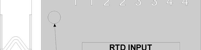
120 Figure RTD Module LED Designations 5-20 Service & Troubleshooting Revised Aug-2015
")
 Modules See Section 3.8 RTD Input Modules See Section 3.")
121 Figure Low Level Analog Input (LLAI) Module LED Designations Checking Wiring/Signals Check I/O field wiring at the terminal blocks and at the field device. Inspect the wiring for continuity, shorts, and opens. Check I/O signals at their respective terminal blocks (see Table 5-2). Table 5-2. I/O Field Wiring - Terminal Block Reference I/O Module or sub-system Notes Digital Input Modules See Section 3.4 Digital Output Modules See Section 3.5 Analog Input Modules See Section 3.6 Analog Output Modules See Section 3.7 Universal Digital Input (UDI) Modules See Section 3.8 RTD Input Modules See Section 3.9 Low Level Analog Input Modules See Section 3.10 Watchdog Circuit See Section Revised Aug-2015 Service & Troubleshooting 5-21
122 5.3.4 Port 80 Display Codes Power-On-Self- Test (POST) Codes The Port 80 Display shows two different types of codes. POST codes, and run-time status codes. When you first power up the ControlWave, or if you reset it using the reset switch, the BIOS runs a power-on-self-test (POST) to test the hardware. Normally, the POST codes pass by too quickly for you to see them, and the system enters normal run time, or if the CPU is set for force recovery mode, you see the code 86. If there is a fault during the POST process, see Table 5-3 for the 2-digit failure code. Table 5-3. Port 80 POST Status Codes HEX Code Definition 00 POST beginning. 01 CPU register test about to start. 02 NMIs are disabled; delay starts. 03 power-on delay finished. 04 kbd BAT done; reading kbd SYS bit. 05 disabling shadowing & cache. 06 calcing ROM cksum, wait kbd ctrllr. 07 cksum okay, kbd ctrllr free. 08 verifying BAT cmd to kbd ctrllr. 09 issuing kbd ctrllr cmd byte. 0A issuing kbd ctrllr data byte. 0B issuing pin 23, 24 blocking & unblocking. 0C issuing kbd ctrllr NOP cmd next. 0D testing CMOS RAM shutdown register. 0E checking CMOS cksum, updating DIAG byte. 0F initializing CMOS (if req d every boot). 10 Init. CMOS status reg. for date/time. 11 disabling DMA, interrupt ctrllrs. 12 disabling Port B, disabling video display. 13 Init. board, start auto-mem detect. 14 starting timer tests. 15 testing 8254 T2, for spkr, part B. 16 testing 8254 T1, for refresh. 17 testing 8254 To, for 18.2 Hz. 18 starting memory refresh. 19 testing memory refresh. 1A testing 15usec refresh ON/OFF time. 1B testing base 64KB memory. 1C testing data lines. 1D currently loading the Boot Project. 20 testing address lines. 21 testing parity (toggling). 22 base 64KB mem read/write test. 23 system init before vector table init. 24 init vector table. 25 reading 8042 for turbo switch setting. 26 initiating turbo data Service & Troubleshooting Revised Aug-2015
123 HEX Code Definition 27 any init after vector table init is next. 28 setting monochrome mode. 29 setting color mode. 2A toggle parity before optional video ROM. 2B init before video ROM check. 2C control passed to video ROM. 2D video ROM returned control. 2E checking for EGA/VGA adapter found. 2F no EGA/VGA found, r/w test of video. 30 looking for video retrace signal. 31 retrace failed, checking alt. Display. 32 alt found, checking video retrace signal. 33 compare switches w/actual adapter type. 34 setting display mode. 35 check ROM BIOS data area at seg 40h. 36 setting cursor for power-on msg. 37 displaying power-on message. 38 save cursor position. 39 display BIOS ident. String. 3A display Hit <DEL> to msg. 40 preparing vm test. vrfy from display. 41 preparing descriptor tables. 42 enter virtual mode for memory test. 43 enable inits for diagnostics mode. 44 init data for checking wraparound at 0:0. 45 checking for wrap, find total memory size. 46 write extended memory test patterns. 47 write conventional memory test patterns. 48 finding low memory size from patterns. 49 finding high memory size from patterns. 4A check ROM BIOS data area again. 4B check for <DEL>, clear low mem for soft reset. 4C clearing ext mem for soft reset. 4D saving memory size. 4E on cold boot, display 1 st 64KB memtest. 4F on cold boot, test all of low memory. 50 adjust memsize for 1K usage. 51 system initialization in progress. 52 prepare for shutdown to real-mode. 53 saved regs & memsize, entering real-mode. 54 shutdown successful, restoring codepath. 55 disabling A20 line. 56 checking ROM BIOS data area again. 57 checking ROM BIOS data area some more. 58 clear the Hit <DEL> message. 59 test DMA page register. 60 verify from display memory (???). 61 test DMA0 base register. 62 test DMA1 base register. 63 checking ROM BIOS data area again. 64 checking ROM BIOS data area some more. 65 programming DMA ctrllrs 0 & 1 66 initializing INT ctrllrs 0 & starting keyboard test. 80 issuing reset cmd & clring output buffer Revised Aug-2015 Service & Troubleshooting 5-23
124 HEX Code Definition 81 check for stuck keys & issue test cmd. 82 initializing circular buffer. 83 check for locked keys. 84 check for memsize mismatch. 85 check for pswd or bypass setup. 86 pswd checked. Do pgming before setup. 87 call the setup module. 88 back from setup, clr screen. 89 display power-on screen message. 8A display Wait message. 8B do system & video BIOS shadowing. 8C load standard setup params into BIOSDATA. 8D check and initialize mouse. 8E check floppy disks. 8F configure floppy drives. 90 check hard disks. 91 configure IDE drives. 92 checking ROM BIOS data area again. 93 checking ROM BIOS data area some more. 94 setting base & ext mem sizes. 95 memsize adjusted for 1K, verifying disp mem. 96 initialization before calling C800h. 97 call ROM BIOS extension at C800h. 98 processing after extension returns. 99 configuring timer data area, printer base addr. 9A configuring serial port base addrs. 9B initialization before coprocessor test. 9C initializing the coprocessor. 9D processing after coprocessor initialized. 9E check ext kbd, kbdid, numlock settings. 9F issue keyboard ID command next. A0 kbd ID flag reset. A1 do cache memory test. A2 display any soft errors. A3 set keyboard typematic rate. A4 program memory wait states. A5 clear screen. A6 enable parity and NMIs. A7 initialization before calling E000h. A8 call ROM BIOS extension at E000h. A9 processing after extension returns. B0 display system config. Box. B1 test low memory exhaustively. B2 test extended memory exhaustively. B3 enumerate PCI space. Run Time Status Codes Once your ControlWave project is normally running, the Port 80 display is usually blank to conserve power. Table 5-4 shows status codes you may see during run-time Service & Troubleshooting Revised Aug-2015
125 Table 5-4. Port 80 Run Time Status Codes ControlWave Instruction Manual HEX Definition Notes Code 00 No Application 01 Application Loaded 10 Application Loaded - BPTs Set Break Point(s) Set 11 Application Running Display Blank 12 Running with BPT Break Point in Debug 1D Currently Loading the Boot Project 51 System Initialization in Progress 86 Recovery Mode SW3-3 = ON; during normal runtime operation you should set SW3-3 to OFF. BA Standby (redundant systems only) Valid Standby (can take over) BC Standby (redundant systems only) Connected to Master BD Standby (redundant systems only) Not Connected to Master BF Battery Fail Check S3-4 CA Hot Card Replacement in Progress CF Invalid Checksum Detected Unit Stopped D0 Diagnostic Mode SW1-8 =OFF D1 Running Diagnostic DE User Application has failed to start Invalid I/O Card configuration F0 NPX Error Unit Stopped F1 Waiting for Power-down After NMI FA CPU Bd. Switch SW1-3 Set OFF Ignore Soft Switch Configuration - Use Flashes for 1 second At startup factory defaults FC Waiting for Alt. Watchdog Timer Unit Stopped FD Waiting for Updump Core Dump in process or waiting to start FE FLASH Programming Error FF Unit Crashed Unit Stopped Reset Switch The reset switch (SW4) is a momentary button that lets you reset (stop and restart) the ControlWave while you test the unit using WINDIAG diagnostic software. Caution Never use the reset switch during normal operation. 5.4 WINDIAG Diagnostic Utility WINDIAG is a software-based diagnostic tool you use to test the performance of I/O modules, CPU memory, communication ports, and other system components.. Revised Aug-2015 Service & Troubleshooting 5-25
126 WINDIAG is a PC-based program, so the ControlWave must be attached to and communicating with a PC running WINDIAG. Set configuration switch SW1-8 OFF (closed) on the CPU module to enable the diagnostic routines. Establish communication between the ControlWave (with/without an application loaded) and the PC with a local or network port under the following conditions: Turn CPU module switches SW1-3 and SW1-8 OFF to run the WINDIAG program. Setting SW1-8 off prevents the boot project from running and places the ControlWave in diagnostic mode. Setting SW1-3 off causes the ControlWave to ignore soft switch settings and use factory defaults; this sets all serial ports to 9600 baud in preparation for the diagnostic tests. Use a null modem cable to connect RS-232 ports between the ControlWave and the PC. Use an RS-485 cable to connect the RS- 485 ports of the ControlWave and the PC. Note: For information on port connections and cabling, please see Chapter 2. See Section for information on communication port defaults. Reserve the port running a diagnostic test for exclusive use; you cannot use that port for any other purpose during testing. Before starting the WINDIAG program, place any critical processes the ControlWave is handling under manual control. You cannot run WINDIAG while the ControlWave is running applications. Set the CPU modules switches SW1-3 and SW1-8 to OFF, and perform the following steps: 1. Start the NetView program in OpenBSI with your current network NETDEF file. A menu displays (similar to the one in Figure 5-19): 5-26 Service & Troubleshooting Revised Aug-2015
. WINDIAG performs the diagnostics and displays pass/fail results. 4.")
127 Figure NetView 2. Select Start >Programs > OpenBSI Tools >Common Tools > Diagnostics. The Main Diagnostics menu (Figure 5-20) displays. Figure WINDIAG Main Diagnostics Menu 3. Select the module to be tested. Enter any prompted parameters (slot #, etc.). WINDIAG performs the diagnostics and displays pass/fail results. 4. After performing all diagnostic testing, exit WINDIAG and then exit the NetView if you don t have any other ControlWave units to test. Revised Aug-2015 Service & Troubleshooting 5-27
128 When you close NetView, the system asks whether you want to close OpenBSI. Select Yes. 5. Set switch SW1-8 on the CPU module to ON (open). The ControlWave should resume normal operation Available Diagnostics Using WINDIAG, you can test all ControlWave modules with the exception of the PSSM. WINDIAG s Main Diagnostics Menu (see Figure 5-20) provides the following diagnostic selections: Option CPU & Peripherals Analog Output High Speed Counter Prom/Ram Analog Input Communications Discrete I/O Ethernet Low Level AI EEPROM Keyboard & Display Tests Checks the CPU module (except for RAM & PROM). Checks AOs on the Analog Output module. Checks the Universal Digital Input (UDI) module. Checks the CPU s RAM and PROM hardware. Checks AIs on the Analog Input module. Checks Communication ports 1 through 4. The loop-back tests require the use of a loop-back plug. Checks DIs on Digital Input Module, DOs on Digital Output Modules. Checks Ethernet Ports 1, 2, or 3. The loop-back tests require the use of a loop-back plug. Checks LLAI modules and RTD modules. Checks the EEPROM. Not applicable. Port Loop-back Test WINDIAG allows you to select the communication port (1 through 4) to test. Depending on the type of network (RS-232 or RS-485) and the port in question, a special loop-back plug is required: Ports 1 and 2 (RS-232) use a 9-pin female D-type loop-back plug (shown in the right side of Figure 5-21). Figure RS-232 Loop-back Plugs 5-28 Service & Troubleshooting Revised Aug-2015
129 Port 3 (RS-232) use an 8-pin male RJ-45 loop-back plug (shown in left side of Figure 5-21). Figure RS-485 Loop-back Plugs Port 3 (RS-485) use an 8-pin male RJ-45 loop-back plug (shown in left side of Figure 5-22). Port 4 (RS-485) use a 9-pin female D-type loop-back plug (shown in right side of Figure 5-22). These tests verify the correct operation of the communication interface on ports COM1 through COM4. Test Procedure Note: You cannot test a communications port while you are using it. You can only test currently unused ports. After you complete testing on all other communication ports (and verify their correct functioning), you must reconnect (using a now validated port) and test the remaining untested port. Use this procedure to test the comm ports. 1. Connect an external loop-back plug to the port on the CPU or SCB port you want to test. Valid ports are: J2 of CPU board for COM1 J3 of CPU board for COM2 J2 of SCB board for COM3 J3 of SCB board for COM4 2. Select Communications on the WINDIAG Main Diagnostics Menu. The Communications Diagnostic screen opens: Revised Aug-2015 Service & Troubleshooting 5-29

130 Figure Communications Diagnostic Menu 3. Enter 5 in the Number of Passes field. 4. Select a port to test (click to display all available ports). Ethernet Port Loop-back Test Note: The port you select must correlate to the port on which you placed the loop-back plug in step Select or ALL ASYNC as the baud rate (click to display all available rates). 6. Click RUN to start the test. At the completion of the test (which generally takes about 5 seconds), any failed results appear in the Status field to the right of the RUN button: TXD RXD Failure CTS RTS Failure 7. Click Return to Menu to display the WINDIAG Main Menu. The Ethernet option on the WINDIAG Main Menu allows you to select the Ethernet communication port (1 through 3) to test. This test configures the Ethernet port s ability to transmit and receive via the twisted pair. The text transmits frames and compares them against received frames. You need a special loop-back plug (shown in Figure 5-24) to perform the Ethernet loop-back test: 5-30 Service & Troubleshooting Revised Aug-2015
, you must reconnect (using a now validated port) and test the remaining untested port.")
131 Figure RJ-45 Ethernet Loop-back Plug Test Procedure Note: You cannot test a communications port while you are using it. You can only test currently unused ports. After you complete testing on all other communication ports (and verify their correct functioning), you must reconnect (using a now validated port) and test the remaining untested port. Use this procedure to test the Ethernet port. 1. Connect an external Ethernet loop-back plug (see Figure 5-24) to the Ethernet port on the CPU module to be tested. 2. Select Ethernet on the WINDIAG Main Diagnostics Menu. The Ethernet Diagnostic screen opens: Figure Ethernet Diagnostic Menu 3. Enter 1 in the Number of Passes field. 4. Enter 1, 2, or 3 in the Ethernet Port to Test field. Revised Aug-2015 Service & Troubleshooting 5-31
132 5. Click RUN next to the Loop-back out twisted pair field to start the test. At the completion of the test, any failed results appear in the Status field next to the Loop-back out twisted pair label: No Hardware Present Loop-back Send Failed Loop-back Receive Failed Loop-back Compare Failed Error Information Returned 6. Disconnect the loop-back plug and reconnect the Ethernet cable to the ControlWave and the Ethernet hub. 7. Click Return to Menu to display the WINDIAG Main Menu. 5.5 Core Updump In some cases such as when a ControlWave fails for no apparent reason you can upload a copy of the contents of SRAM and SDRAM to a PC for support personnel and service engineers to evaluate. This upload is called a core updump. A core updump may be required if the ControlWave spontaneously enters a watchdog state that affects all system operation. This occurs when the system crashes as a result of a CPU timeout (resulting from improper software operation, a firmware glitch, and so on). In some cases, the watchdog state can recur but you cannot logically reproduce the conditions. The CPU module s RAM contains crash blocks, a firmware function provided specifically for watchdog troubleshooting. You can view and save the crash blocks by viewing the Crash Block Statistic Web Page (see the Web_BSI Manual, D5087). On request, you can forward crash block files to our technical support personnel. If they need additional information to evaluate the condition, the technical support group may request a core updump. Once the core updump process generates a file, you can forward that file to the support personnel for evaluation and resolution. Use the following steps to preserve the failed state condition at a system crash and perform a core updump: 1. Set switch SW1-1 on the CPU module to OFF (Disable Watchdog Timer). Set switch SW1-4 to OFF (Enable Core Updump). 2. Wait for the error condition (typically FF on the Port 80 display). 3. Connect the ControlWave Comm Port 1 to a PC using a null modem cable. 4. Operate the Run/Remote/Local switch as follows: Note: You must perform each step in less that one second Service & Troubleshooting Revised Aug-2015
133 a. Set Run/Remote/Local switch to Run b. Set Run/Remote/Local switch to Remote c. Set Run/Remote/Local switch to Local d. Set Run/Remote/Local switch back to Remote e. Set Run/Remote/Local switch back to Local 5. Start the PC s HyperTerminal program (at kbaud) and generate a receive using the 1KX-Modem protocol. Save the resulting core updump in a file so you can forward it later to the technical support group. By setting the CPU module switches SW1-1 and SW1-4 both off before the ControlWave fails, you prevent the ControlWave from automatically recovering from the failure and enable it to wait for you to take a core updump. Once you complete the core updump, set the CPU module s switch SW1-1 to ON (Watchdog Enabled) and SW1-4 to ON (Normal Run). With these switches set, power up the ControlWave and recommence standard operations. When the active unit of a ControlWave Redundant Controller fails, it does not recover but forces the watchdog relay so the standby unit takes over. Once the core updump completes, set the failed unit s CPU switch SW1-1 to ON and SW1-4 to ON, if required, and then power cycle the failed unit to receive the sideload to become a valid standby unit. This applies to the ControlWave REDIO as well. Revised Aug-2015 Service & Troubleshooting 5-33
134 This page is intentionally left blank
135 Appendix A ControlWave Process Automation Controller Special Instructions for Class I, Division 2 Hazardous Locations 1. The ControlWave Process Automation Controller is listed by Underwriters Laboratories (UL) as nonincendive and is suitable for use in Class I, Division 2, Groups A, B, C and D hazardous locations and non-hazardous locations only. Read this appendix carefully before installing a nonincendive ControlWave Process Automation Controller. In the event of a conflict between the main body of this manual and this appendix, always follow the instructions in this appendix. 2. All power and I/O wiring must be performed in accordance with Class I, Division 2 wiring methods as defined in Article (b) of the National Electrical Code, NFPA 70, for installations within the United States, or as specified in Section of the Canadian Electrical Code for installation in Canada. WARNING EXPLOSION HAZARD Substitution of components may impair suitability for use in Class I, Division 2 environments. WARNING EXPLOSION HAZARD When situated in a hazardous location, turn off power before servicing / replacing the unit and before installing or removing I/O wiring. WARNING EXPLOSION HAZARD Do NOT disconnect equipment unless the power has been switched off or the area is known to be non-hazardous. Revised Aug-2015 Appendix A A-1
136 This page is intentionally left blank

 Lithium Thionyl Chloride Battery (1/2 AA, 3.")
137 Appendix Z Sources for Obtaining Material Safety Data Sheets This device includes certain components or materials which may be hazardous if misused. For details on these hazards, please contact the manufacturer for the most recent material safety data sheet. Manufacturer Eagle Picher SAFT America General Description Lithium Thionyl Chloride Battery (1/2 AA, 3.6V, 950 mah - On-board) Lithium Thionyl Chloride Battery (1/2 AA, 3.6V, 950 mah - On-board) Emerson Part Number & Media Notes Eagle Picher P/N LTC-9C SAFT P/N LS Revised Aug-2015 Appendix Z Z-1
ControlWave Micro Distributed I/O System
 Instruction Manual Part Number D301772X012 August 2015 ControlWave Micro Distributed I/O System Remote Automation Solutions www.emersonprocess.com/remote IMPORTANT! READ INSTRUCTIONS BEFORE STARTING! Be
ControlWave Gas Flow Computer
 ControlWave Gas Flow Computer Instruction Manual Doc Number CI-ControlWave GFC Part Number D301387X012 November 2011 Remote Automation Solutions www.emersonprocess.com/remote This page is intentionally
File E Project 00NK September 15, 2000 REPORT TELEMETERING EQUIPMENT FOR USE IN HAZARDOUS LOCATIONS. Bristol Babcock Inc.
 File E165662 Project 00NK05857 September 15, 2000 REPORT on TELEMETERING EQUIPMENT FOR USE IN HAZARDOUS LOCATIONS Bristol Babcock Inc. Watertown, CT Copyright 2000 Underwriters Laboratories Inc. Underwriters
TRC-190 User s Manual
 User s Manual Edition 3.2, May 2017 www.moxa.com/product 2017 Moxa Inc. All rights reserved. User s Manual The software described in this manual is furnished under a license agreement and may be used only
ControlWave EFM (Electronic Flow Meter)
") Instruction Manual Doc Number CI-ControlWave EFM Part Number D301383X012 December 2013 ControlWave EFM (Electronic Flow Meter) Remote Automation Solutions www.emersonprocess.com/remote IMPORTANT! READ
Instruction Manual Doc Number CI-ControlWave EFM Part Number D301383X012 December 2013 ControlWave EFM (Electronic Flow Meter) Remote Automation Solutions www.emersonprocess.com/remote IMPORTANT! READ
Vision OPLC. V T38 Installation Guide. General Description
 Vision OPLC V130-33-T38 Installation Guide The Unitronics V130-33-T38 offers the following onboard I/Os: 22 Digital Inputs, configurable via wiring to include 2 Analog and 2 HSC/Shaft-encoder Inputs 16
RAD-DO8-IFS. I/O extension module, eight digital transistor outputs. Data sheet. 1 Description
 I/O extension module, eight digital transistor outputs Data sheet 105364_en_00 PHOENIX CONTACT 2013-03-26 1 Description The I/O extension module can be used in conjunction with Radioline wireless modules
Rhino Buffer Module PSM24-BFM600S. Operating Instructions
 Rhino Buffer Module PSM24-BFM600S Operating Instructions RHINO BUFFER MODULE PSM24-BFM600S Description The PSM24-BFM600S Buffer Module will hold the output voltage of a 24 VDC power supply after brownouts
PanelView Plus/VersaView CE Terminals and Display Modules
 Installation Instructions PanelView Plus/VersaView CE Terminals and Display Modules (Catalog Numbers 2711P-xxxxxx, 6182H-xxxxxx) English Inside: Overview...2 For More Information...2 Modular Components...3
VL BPC MINI. A configurable industrial computer platform. Data sheet 2930_en_F. 1 Description. 2 Features
 A configurable industrial computer platform Data sheet 90_en_F Description PHOENIX CONTACT 0-08- Features The VL BPC MINI is an embedded box PC and is part of the Valueline family of industrial computers.
Installation and Wiring
 Wiring 2 2 Plan for Safety Safety Techniques WARNING: Providing a safe operating environment for personnel and equipment is your responsibility and should be your primary goal during system planning and
Replacing the Power Supply
 APPENDIX B This appendix includes information on how to replace the power supply for the Cisco AS550XM universal gateway and contains the following sections: Safety Recommendations, page B-1 Required Tools
Perle SMI Media Converter Installation Guide
 Perle SMI Media Converter Installation Guide P/N 5500316-14 Overview This guide contains instructions necessary for the installation and operation of the Perle SMI Media Converter. This media converter
When any of the following symbols appear, read the associated information carefully. Symbol Meaning Description
 Vision OPLC V350-35-R34/V350-J-R34 Installation Guide The Unitronics V350-35-R34/V350-J-R34 offers the following onboard I/Os: 22 Digital Inputs, configurable via wiring to include 2 Analog and 3 HSC/Shaft-encoder
MC 11 EB-2 Power supply cabinet with external bus, AC version
 MC 11 EB-2 Power supply cabinet with external bus, AC version USER/MAINTENANCE MANUAL 1 SLOT 0 SLOT 1 SLOT 2 SLOT 3 SLOT 4 SLOT 5 SLOT 6 SLOT 7 SLOT 8 SLOT 9 SLOT 10 SLOT 11 EB-2 (a) MC11 (b) (c) Figures
TRC-190 User s Manual
 First Edition, November 2008 www.moxa.com/product 2008 Moxa Inc. All rights reserved. Reproduction without permission is prohibited. The software described in this manual is furnished under a license agreement
IC693PWR331 High Capacity Power Supply, 24 VDC Input
 IC693PWR331 High Capacity Power Supply, 24 VDC Input The Series 90-30 DC input High Capacity power supply (IC693PWR33) is a 30 watt wide range supply designed for 24 VDC nominal inputs. For applications
RAD-DI8-IFS. I/O extension module with 8 digital inputs or 2 pulse inputs. INTERFACE Data sheet. 1 Description
 I/O extension module with 8 digital inputs or 2 pulse inputs INTERFACE Data sheet 0483_en_00 PHOENIX CONTACT 203-04-05 Description The I/O extension module can be used in conjunction with Radioline wireless
PIX 535. PIX 535 Product Overview CHAPTER
 CHAPTER 7 PIX 535 This chapter describes the installation of the PIX 535, and includes the following sections: PIX 535 Product Overview Installing a PIX 535 PIX 535 Feature Licenses Installing Failover
2562 QUICK START GUIDE
 2562 QUICK START GUIDE CTI P/Ns: 2562 Quick Start Guide: 062-00348-010 2562 Installation and Operation Guide: 062-00332-011 Summary: The 2562 is designed to translate a digital word from the programmable
RTU560 Connections and Settings DIN Rail RTU 560CIG10
 Connections and Settings DIN Rail RTU 560CIG10 Application, characteristics and technical data have to be taken from the hardware data sheet: 560CIG10 1KGT 150 719 Operation The 560CIG10 is a DIN rail
22 Digital Inputs, including 2 Analog, 2 HSC/Shaft-encoder inputs 16 Transistor Outputs
 Vision PLC+HMI V130-33-T38/V130-J-T38 V350-35-T38/V350-J-T38 V430-J-T38 Installation Guide 22 Digital Inputs, including 2 Analog, 2 HSC/Shaft-encoder inputs 16 Transistor Outputs General Description All
ControlWave PAC Redundant Systems
 CWPAC:RDN Product Data Sheet D301305X012 August 2017 ControlWave PAC Redundant Systems Emerson s ControlWave PAC redundant systems are designed to prevent a single point of failure from shutting down the
VL BPC 100. Valueline configurable box PC. Data sheet 3063_en_E. 1 Description. 2 Features
 Valueline configurable box PC Data sheet 0_en_E Description PHOENIX CONTACT 0-07- Features The VL BPC 000 is a configurable box PC that can be mounted either directly on a wall or on a DIN rail. The VL
Vision OPLC V TR6/V350-J-TR6
 Vision OPLC V350-35-TR6/V350-J-TR6 Installation Guide The Unitronics V350-35-TR6/V350-J-TR6 offers the following onboard I/Os: 8 Digital Inputs, configurable via wiring to include 2 Analog (current/voltage)
This guide provides basic information for Unitronics controller model V T2.
 Vision OPLC 12 pnp/npn Digital, including 2 Analog, 3 HSC/Shaftencoder Inputs, 12 Transistor Outputs This guide provides basic information for Unitronics controller model V350-35-T2. General Description
VL BPC MINI. A configurable industrial computer platform Intel Atom Z510PT CMAT IPC Module Option [I28] AUTOMATION Data Sheet 2930_en_A.
![VL BPC MINI. A configurable industrial computer platform Intel Atom Z510PT CMAT IPC Module Option [I28] AUTOMATION Data Sheet 2930_en_A.](/thumbs/72/66783612.jpg "VL BPC MINI. A configurable industrial computer platform Intel Atom Z510PT CMAT IPC Module Option [I28] AUTOMATION Data Sheet 2930_en_A.") A configurable industrial computer platform Intel Atom Z0PT CMAT IPC Module Option [I8] AUTOMATION Data Sheet 90_en_A Description PHOENIX CONTACT 0-0-0 Features The VL BPC MINI is an embedded box PC and
A configurable industrial computer platform Intel Atom Z0PT CMAT IPC Module Option [I8] AUTOMATION Data Sheet 90_en_A Description PHOENIX CONTACT 0-0-0 Features The VL BPC MINI is an embedded box PC and
Perle MCR200 Installation Guide
 Perle MCR200 Installation Guide P/N 5500322-10 Introduction The Perle MCR200 Chassis is a 2 slot chassis able to accommodate up to 2 Perle Media Converter modules or 1 Media Converter Module and an MCR-MGT
Rhino Redundancy Module PSM24-REM360S. Operating Instructions
 Rhino Redundancy Module PSM4-REM360S Operating Instructions RHINO REDUNDANCY MODULE PSM4-REM360S Description With this module and two power supplies of the PSM series (78, 90, 56, 80 and 360 watt models),
Installation Instructions
 Installation Instructions (1771-ODD Series B) Use this document as a guide when installing the catalog number 1771-ODD series B output module. The ac isolated output module is shipped in static-shielded
P3-RS Remote Slave Module
 P3-RS Rack with CPU Module Racks with P3-RS Modules The P3-RS is a full-featured, highperformance, Remote Slave module. Features include a line x 0 charactor LCD display and five communications ports
Vision OPLC. General Description. Standard Kit Contents. Installation Guide Vision120. This guide provides basic information for Unitronics Vision120.
 Vision OPLC Installation Guide Vision120 This guide provides basic information for Unitronics Vision120. General Description V120 OPLCs are micro-oplcs, rugged programmable logic controllers that comprise
PACSystems* RX3i IC695PSA040
 August 2012 PACSystems* RX3i IC695PSA040 Power Supply, 120/240VAC or 125VDC, 40 Watts The PACSystems * RX3i power supply IC695PSA040 is a 40-Watt supply that operates from an input voltage source in the
PIX 520. PIX 520 Product Overview CHAPTER
 CHAPTER 5 PIX 520 This chapter guides you through the installation of the PIX 520, and includes the following sections: PIX 520 Product Overview, page 5-1 Installing the PIX 520, page 5-4 PIX 520 Feature
RMB Peripheral Units Installation Guide
 RMB Peripheral Units Installation Guide Part Number 65-000101 2011 by Kentrox, Inc. All rights reserved. Copyright 2011 by Kentrox, Inc. All Rights Reserved. The material discussed in this publication
Junos WebApp Secure 5.0 Hardware Guide
 Junos WebApp Secure 5.0 Hardware Guide Junos WebApp Secure 5.0 Hardware Guide This document contains a specification for the MWS1000 hardware appliance, as well as instructions for installation into a
Installation Guide V290 (Color) This guide provides basic information for Unitronics LCD color touchscreen models V C30B and V T40B.
 This guide provides basic information for Unitronics LCD color touchscreen models V C30B and V T40B.") Vision OPLC Installation Guide V290 (Color) This guide provides basic information for Unitronics LCD color touchscreen models V290-19-C30B and V290-19-T40B. General Description Vision OPLCs are programmable
Vision OPLC Installation Guide V290 (Color) This guide provides basic information for Unitronics LCD color touchscreen models V290-19-C30B and V290-19-T40B. General Description Vision OPLCs are programmable
Installation Job Aid for VSP 4850GTS
 Installation Job Aid for VSP 4850GTS Notices Release 6.1.0.0 NN46251-308 Issue 02.01 November 2017 Notice paragraphs alert you about issues that require your attention. The following paragraphs describe
Instruction Sheet Board Style Low Water Cutoff
 Instruction Sheet Board Style Low Water Cutoff 102-305 SUPERSEDES: REVISION E DATED December 12, 2007 #5401173-REV F PLANT ID 001-3902 US Patents 6,904,800, 7,243,540, and 7,317,993 Other Patents Pending
ControlWave PAC Process Automation Controller
 ControlWave PAC Process Automation Controller December 2010 The ControlWave PAC is a highly adaptable Process Automation Controller with exceptional networking capability. Designed with an emphasis on
P3-SCM. General Specifications
 General Specifications Module Type Modules per Base Modules per Group I/O Points Used Field Wiring Connector Operating Temperature Storage Temperature Humidity Environmental Air Vibration Shock Field to
INSTALLATION INSTRUCTIONS
 www.altroniccontrols.com INSTALLATION INSTRUCTIONS EXACTA 21 MONITORING AND CONTROL SYSTEM CAUTION: The EXACTA 21 CONTROL SYSTEM is CSA CERTIFIED FOR use in Class I, GROUPS C & D, Division 2 hazardous
REDUNDANCY MODULE TSP-REM360 AND TSP-REM600
 REDUNDANCY MODULE TSP-REM360 AND TSP-REM600 Operating Instructions Seite 1 Dimensions drawings: TSP-REM360 Weight: 0.882lb Gewicht: 0.40kg Seite 2 Dimensions drawings: TSP-REM600 Bottom view Top view Side
When any of the following symbols appear, read the associated information carefully. Symbol Meaning Description
 Uni-I/O Wide Modules Installation Guide UIS-WCB1 Uni-I/O Wide is a family of Input/Output modules that are compatible with the UniStream control platform. Wide Modules are 1.5 times as wide as Uni-I/O
iopac 8500 Series Rugged modular RTU controllers Overview Programmable Controllers High Sampling Rate Analog Input Prerecord Feature
 Programmable Controllers iopac 8500 Series Award-winning Product Rugged modular RTU controllers Dedicated ARM (RISC) CPUs for the main system and each I/O module Millisecond timestamp granularity for digital
Vision OPLC V TR20
 Vision OPLC V130-33-TR20 Installation Guide The Unitronics V130-33-TR20 offers the following onboard I/Os: 12 Digital Inputs, configurable via wiring to include 2 Analog, and 3 HSC/Shaft-encoder Inputs
PACSystems* RX3i IC695PSA140
 August 2012 PACSystems* RX3i IC695PSA140 120/240VAC or 125VDC, 40 Watts The PACSystems * RX3i IC695PSA140 is a multi-purpose 40-Watt supply that operates from an input voltage source in the range of 85
ControlWave PAC Process Automation Controller
 CWPAC Product Data Sheet D301303X012 October 2012 ControlWave PAC Process Automation Controller The ControlWave PAC is a highly adaptable Process Automation Controller with exceptional networking capability.
FLEX Ex Spring Clamp Terminal Base
 Installation Instructions FLEX Ex Spring Clamp Terminal Base (Cat. No. 1797-TB3S) 1 10 11 4 Only remove this cover plug if connecting another terminal base unit. 3 5 6 12 2 7 8 9 41253 Component Identification
DLA. DMX512 Analyzer. DLA Users Manual SV2_00 B.lwp copyright ELM Video Technology, Inc.
 DLA DMX512 Analyzer DLA DLA-HH 1 Table Of Contents IMPORTANT SAFEGUARDS... 2 DLA OVERVIEW... 3 CONNECTION... 3 OPERATION... 3 HARDWARE SETUP... 4 DLA-HH (PORTABLE) LAYOUT... 4 CHASSIS LAYOUT... 4 DLA MENU
Model 2460-KIT. Screw Terminal Connector Kit. Description / September 2014 *P * 1
 Keithley Instruments 28775 Aurora Road Cleveland, Ohio 44139 1-800-935-5595 http://www.keithley.com Model 2460-KIT Screw Terminal Connector Kit Description The Model 2460-KIT Screw Terminal Connector Kit
D115 The Fast Optimal Servo Amplifier For Brush, Brushless, Voice Coil Servo Motors
 D115 The Fast Optimal Servo Amplifier For Brush, Brushless, Voice Coil Servo Motors Ron Boe 5/15/2014 This user guide details the servo drives capabilities and physical interfaces. Users will be able to
Vision OPLC V TR20
 Vision OPLC V130-33-TR20 Installation Guide The Unitronics V130-33-TR20 offers the following onboard I/Os: 12 Digital Inputs, configurable via wiring to include 2 Analog, and 3 HSC/Shaft-encoder Inputs
The identified danger could cause physical and property damage.
 Samba OPLC SM35-J-T20 Installation Guide The Unitronics SM35-J-T20 offers the following onboard I/Os: 12 Digital Inputs, configurable via wiring to include 2 Analog and 3 HSC/Shaft-encoder Inputs 8 Transistor
1395 Node Adapter Board Troubleshooting
 1395 Node Adapter Board Troubleshooting Specifications Electrical: Board power provided by Drive (+5V) Discrete Input 24V DC or 115V AC, jumper selectable Environmental: Ambient Operating Temperature Storage
V TU24 V350-J-TU24
 Vision PLC+HMI V350-35-TU24 V350-J-TU24 Installation Guide 12 Digital Inputs, including 2 Analog, 2 PT100/TC,1 HSC/Shaft-encoder input 12 Transistor Outputs General Description All of the controllers covered
PBSCONTROL. AMS-R4000 Modular RTU. Remote Terminal Unit
 PBSCONTROL AMS-R4000 Modular RTU Remote Terminal Unit AMS-R4000 Introduction The documentation and the software included with this product are copyrighted 2017 by pbscontrol Company. AMS-4000 System is
Screen 2.4" 3.5" Color Touch 4.3" Color Touch. RS232/485 Yes Yes Yes Yes Yes* USB device, mini-b Com Ports, separate order, user-installed
 V130-33-TR20/V130-J-TR20 V350-35-TR20/V350-J-TR20 V430-J-RH2 Installation Guide 12 Digital Inputs, including 2 Analog, 3 HSC/Shaft-encoder inputs 6 Relay Outputs 2 high-speed npn Transistor Outputs (TR20
Installation and Maintenance
 CHAPTER 4 Installation and Maintenance Revised: April 19, 2010, Introduction This chapter explains how to install a SCE 1000 platform in a rack or in a general tabletop or workbench installation. Additionally,
RAD-DOR4-IFS. I/O extension module, 4 digital relay outputs. INTERFACE Data sheet. 1 Description
 I/O extension module, 4 digital relay outputs INTERFACE Data sheet 104834_en_01 PHOENIX CONTACT 2013-01-21 1 Description The RAD-DOR4-IFS I/O extension module can be used in conjunction with Radioline
MGate 5105-MB-EIP Series
 MGate 5105-MB-EIP Series 1-port Modbus RTU/ASCII/TCP-to-EtherNet/IP gateways Features and Benefits Protocol conversion between Modbus and EtherNet/IP Supports EtherNet/IP Scanner/Adapter Supports Modbus
General Specifications. P2-SCM Serial Communications
 General Specifications Module Type Intelligent Modules per Base I/O Points Used Field Wiring Connector Operating Temperature Storage Temperature Humidity Environmental Air Vibration Shock Field to Logic
ControlWave Micro Digital Input / Output Modules
 May 2011 ControlWave Micro Digital Input / Output Modules The Digital Input (DI), Digital Output (DO), and Digital Input/Output (DI/O) modules provide the ControlWave Micro with the ability to monitor
PHOENIX CONTACT - 05/2007
 Ex Universal Module Carrier (Motherboard) for Accommodating 3-Wire Measuring Transducers, Intrinsically Safe, for a Maximum of 8 PI Ex Modules INTERFACE Data Sheet 103030_00_en PHOENIX CONTACT - 05/2007
Remote RMM-1400 Intelligent Remote Site Management Device. Installation Guide
 Remote RMM-1400 Intelligent Remote Site Management Device Guide INSTALLATION GUIDE Westell Technologies Part # 030-300645 Rev. A Copyright 2015 by Westell Technologies. All Rights Reserved. Westell, Kentrox
General Description V TR34/V130-J-TR34 V TR34/V350-J-TR34 V430J-R34 V R34/V130-J-R34 V R34/V350-J-R34
 Vision OPLC V130-33-TR34/V130-J-TR34 V350-35-TR34/V350-J-TR34 V430-J-TR34 V130-33-R34/V130-J-R34 V350-35-R34/V350-J-R34 V430-J-R34 Installation Guide 22 Digital Inputs, including 3 HSC/Shaft-encoder Inputs,
CONTROL MICROSYSTEMS Differential Analog Input Module. Hardware Manual
 550 Differential Analog Input Hardware Manual CONTROL MICROSYSTEMS SCADA products... for the distance Steacie Drive Telephone: 63-59-93 Kanata, Ontario Facsimile: 63-59-0 KK A9 Technical Support: -6-676
TrendView recorders - Installation Instruction
 TrendView recorders - Installation Instruction Analogue In / Analogue Out / Pulse Input cards / Alarm Relay and Digital Input / Output cards QX Recorder SX Recorder QXe Recorder DR Graphic Recorder This
iopac 8020 Series Rugged modular RTU controllers Overview Programmable RTU Controllers Ethernet bypass feature for seamless data transmission
 iopac 8020 Series Rugged modular RTU controllers Compliant with EN 50121-3-2, EN 50121-4, and a portion of EN 50155 specifications Supports C/C++ programming languages 2-port Ethernet switch for daisy-chain
OPLC Installation Guide
 Samba OPLC SM35-J-R20/SM43-J-R20 SM70-J-R20 SM35-J-T20/SM43-J-T20 SM70-J-T20 OPLC Installation Guide 12 Digital Inputs, include 1 HSC/Shaft-encoder Input, 2 Analog inputs (only when the digital inputs
Quick Start Installation Guide
 apc/l Quick Start Installation Guide Version A2 Document Part Number UM-201 May 2010 OVERVIEW The apc/l is an intelligent access control and alarm monitoring control panel which serves as a basic building
CONTROL MICROSYSTEMS Thermocouple Analog Input Module. Hardware Manual
 550 Thermocouple Analog Input Hardware Manual CONTROL MICROSYSTEMS SCADA products... for the distance Steacie Drive Telephone: 63-59-93 Kanata, Ontario Facsimile: 63-59-0 KK A9 Technical Support: -6-676
USP-070-B08 USP-104-B10, USP-104-M10 USP-156-B10
 UniStream HMI Panel Installation Guide USP-070-B10, USP-070-B08 USP-104-B10, USP-104-M10 USP-156-B10 Unitronics UniStream platform comprises control devices that provide robust, flexible solutions for
CONTROL MICROSYSTEMS and 5407 Relay Output Module. Hardware Manual
 506 and 507 Relay Output Module Hardware Manual CONTROL MICROSYSTEMS SCADA products... for the distance Steacie Drive Telephone: 63-59-93 Kanata, Ontario Facsimile: 63-59-0 KK A9 Technical Support: -6-676
Installing and Removing SDRAM and DRAM
 CHAPTER 4 This chapter explains how to remove and replace the main memory modules on the network processing engine or network services engine. For the location of the memory module you are replacing, find
XPSMF40. Main. Safety module name. Monitoring safety detection discrete input Monitoring safety dialogue discrete output
 Product datasheet Characteristics XPSMF4000 Preventa safety PLC compact - Safe Ethernet Main Range of product Product or component type Safety module name Safety module application Preventa Safety automation
Serial Data DIN Fiber Link System
 USER GUIDE RLH Industries, Inc. The leader in rugged fiber optic technology. U-120 2017A-0420 DIN Fiber Link System COMPACT, RUGGED & TEMPERATURE HARDENED Introduction The DIN Fiber Link system transports
Allen-Bradley. User Manual. PLC-5 Backup Communication Module (1785-BCM, 1785-BEM) product icon
 product icon") Allen-Bradley PLC-5 Backup Communication Module User Manual (1785-BCM, 1785-BEM) product icon Important User Information Because of the variety of uses for this product and because of the differences between
Allen-Bradley PLC-5 Backup Communication Module User Manual (1785-BCM, 1785-BEM) product icon Important User Information Because of the variety of uses for this product and because of the differences between
PIX 515/515E. PIX 515/515E Product Overview CHAPTER
 CHAPTER 4 PIX 515/515E This chapter describes how to install the PIX 515/515E, and includes the following sections: PIX 515/515E Product Overview Installing a PIX 515/515E PIX 515/515E Feature Licenses
Installation Instructions
 Installation Instructions Cat. No. 1771 P3, P4, P5 and P5E Use this document as a guide when installing the catalog number 1771-P3, -P4, -P5 or -P5E power supplies. Because of the variety of uses for the
Installation and Configuration Guide
 Installation and Configuration Guide Trademark Notices Comtrol, NS-Link, and DeviceMaster are trademarks of Comtrol Corporation. Microsoft and Windows are registered trademarks of Microsoft Corporation.
Digital ac/dc (24V) Input Module
 Input Module") Installation Instructions Digital ac/dc (24V) Input Module Catalog Number 1771-IND, Series C Topic Page Important User Information 2 Before You Begin 3 Power Requirements 3 Prevent Electrostatic Discharge
Installation Instructions Digital ac/dc (24V) Input Module Catalog Number 1771-IND, Series C Topic Page Important User Information 2 Before You Begin 3 Power Requirements 3 Prevent Electrostatic Discharge
RTU560 Remote Terminal Unit Connections and Settings
 Remote Terminal Unit Connections and Settings Communication Unit 560CMG10 Application, characteristics and technical data have to be taken from the hardware data sheet: 560CMG10 1KGT 150 645 Operation
Cisco ONS CL Shelf Assembly Hardware
 CHAPTER 1 This chapter provides a description of Cisco ONS 15310-CL shelf hardware. Instructions for installing equipment are provided in the Cisco ONS 15310-CL and Cisco ONS 15310-MA Procedure Guide.
P USB 2.0 (Type B) Port - Programming - Online monitoring
 Port - Programming - Online monitoring") P3-0 CPU Module Company Information Systems Overview P3-0 The P3-0 is a full-featured, highperformance CPU. Features include a line x 10 character LCD and seven communications ports which support
P3-0 CPU Module Company Information Systems Overview P3-0 The P3-0 is a full-featured, highperformance CPU. Features include a line x 10 character LCD and seven communications ports which support
OPTICAL HEADEND PLATFORM OTOHP-CH 3RU CHASSIS OTOHP-PS POWER SUPPLY MODULE OTOHP-BP BLANK PANEL INSTRUCTION MANUAL
 OPTICAL HEADEND PLATFORM OTOHP-CH 3RU CHASSIS OTOHP-PS POWER SUPPLY MODULE OTOHP-BP BLANK PANEL INSTRUCTION MANUAL Phone: (209) 586-1022 (800) 545-1022 Fax: (209) 586-1026 OTOHP-CH Rev. X1 E-Mail: salessupport@olsontech.com
Perle Gigabit Media Converter Module. Installation Guide P/N
 Perle Gigabit Media Converter Module Installation Guide Unmanaged Managed C-1000-M2SC05 C-1000-M2LC05 C-1000-S2LC10 C-1000-S2SC10 C-1000-S2LC40 C-1000-S2SC70 C-1000-S2LC70 C-1000-S1SC10U C-1000-S1SC10D
Installation Guide V290 (Color) This guide provides basic information for Unitronics LCD color touchscreen models V C30B and V T40B.
 This guide provides basic information for Unitronics LCD color touchscreen models V C30B and V T40B.") Vision OPLC Installation Guide V290 (Color) This guide provides basic information for Unitronics LCD color touchscreen models V290-19-C30B and V290-19-T40B. General Description Vision OPLCs are programmable
Vision OPLC Installation Guide V290 (Color) This guide provides basic information for Unitronics LCD color touchscreen models V290-19-C30B and V290-19-T40B. General Description Vision OPLCs are programmable
TraceTek Leak Detection Master Module Installation Instructions TOOLS REQUIRED STORAGE
 TTDM-128 TraceTek Leak Detection Master Module Installation Instructions TRACETEK APPROVALS AND CERTIFICATIONS TYPE NM General Signaling Equipment 76LJ GENERAL INFORMATION Please read these instructions
Installing the Cisco ADE 2130 and 2140 Series Appliance Hardware Options
 CHAPTER 4 Installing the Cisco ADE 2130 and 2140 Series Appliance Hardware Options This chapter provides instructions for installing, replacing, and removing various hardware options in your Cisco ADE
When any of the following symbols appear, read the associated information carefully. Symbol Meaning Description
 Uni-I/O Modules Installation Guide UIS-04PTN Uni-I/O is a family of Input/Output modules that are compatible with the UniStream control platform. This guide provides basic installation information for
When any of the following symbols appear, read the associated information carefully. Symbol Meaning Description
 Uni-I/O Modules Installation Guide UID-0808R, UID-0808T, UID-1600,UID-0016R, UID-0016T Uni-I/O is a family of Input/Output modules that are compatible with the UniStream control platform. This guide provides
TPE 1464 Series Pressure Transducer
 TPE 1464 Series Pressure Transducer Description The KMC TPE 1464 series of pressure transducers incorporate a gauge pressure transmitter featuring low hysteresis, excellent repeatability, and longterm
EOS-6000 Series Optical A/B Switch User Manual DC Version
 EOS-6000 Series Optical A/B Switch User Manual DC Version For more information on this and other products: Contact Sales at EMCORE 626-293-3400, or visit www.emcore.com. Table of Contents Table of Contents...2
Installation Job Aid for VSP 4450GTX-HT- PWR+
 Installation Job Aid for VSP 4450GTX-HT- PWR+ Notices Release 6.1.0.0 NN46251-305 Issue 02.01 November 2017 Notice paragraphs alert you about issues that require your attention. The following paragraphs
This guide provides basic information for Unitronics controllers V C30B and V T40B.
 Vision OPLC V570-57-C30B and V570-57-T40B (Color) This guide provides basic information for Unitronics controllers V570-57-C30B and V570-57-T40B. General Description Vision OPLCs are programmable logic
Installation Instructions
 Installation Instructions (Catalog Number 1771-OD) This document provides information on: Because of the variety of uses for the products described in this publication, those responsible for the application
When any of the following symbols appear, read the associated information carefully. Symbol Meaning Description
 Uni-I/O Modules Installation Guide UIA-0402N Uni-I/O is a family of Input/Output modules that are compatible with the UniStream control platform. This guide provides basic installation information for
When any of the following symbols appear, read the associated information carefully. Symbol Meaning Description
 Uni-COM Modules Installation Guide UAC-01RS2,UAC-02RS2,UAC-02RSC Uni-COM is a family of communication modules that are compatible with the UniStream control platform. This guide provides basic installation
OpenBSI Harvester Manual
 User Manual Document: D5120 Part: D301421X012 May 2013 OpenBSI Version 5.9 OpenBSI Harvester Manual Remote Automation Solutions www.emersonprocess.com/remote IMPORTANT! READ INSTRUCTIONS BEFORE STARTING!