Sport SX/Sport EX/Horizon EX. Installation Manual
|
|
|
- Phebe Boyd
- 6 years ago
- Views:
Transcription


1 Sport SX/Sport EX/Horizon EX Installation Manual Revision G 20-April-2017
2 Copyright Madison Ave. SE Wyoming, MI (616) ii Revision F
3 SPORT Installation Manual FORWARD Congratulations on your purchase of the EFIS! We are pleased that you have chosen our product to meet your flying needs. This manual describes installation of the GRT Sport SX/EX and Horizon EX EFIS using the software version shown in the Record of Revisions. Some differences may be observed when comparing the information in this manual to other software versions. Every effort has been made to ensure that the information in this manual is accurate and complete. Visit the Grand Rapids Technologies (GRT) website, for the latest manual updates, software updates and supplemental information concerning the operation of this and other GRT products. GRT is not responsible for unintentional errors or omissions in the manual or their consequences. Information in the document is subject to change without notice. Grand Rapids Technologies reserves the right to change or improve their products and to make changes in the content of this material without obligation to notify any person or organization of such changes or improvements. Copyright Grand Rapids Technologies or its subsidiaries. All rights reserved. Revision F iii
4 RECORD OF REVISIONS Revision A B D E F Date 1- May April Dec Mar Nov Sport SX SW Rev N/A 3f 8g Sport EX SW Rev Change Description Initial Release Extensive Complete Reissue 11 Addition of adaptive AHRS 11 Numerous updates. Added Sport EX/Horizon EX. G 11 All AOA Install, Both set of mag wire colors added. iv Revision F
5 SPORT Installation Manual TABLE OF CONTENTS RECORD OF REVISIONS...iv SECTION 1: GENERAL DESCRIPTION...8 Introduction...8 Certification...8 System Description & Architecture...8 Display Unit Features & Limitations...9 Light Aircraft Avionics Primer...10 Gray-Code Altitude Encoder Output (Applies to Sport SX Only)...14 USB Port...14 Physical Wiring...14 Optional Features - (Sport EX Only)...15 Analog Inputs/Audio Output - (Sport/Horizon EX only)...15 Basic Engine Monitoring Functions - (Sport/Horizon EX Only)...16 Optional Features - (Sport SX Only)...16 For More Information...16 SECTION 2: MECHANICAL INSTALLATION...17 Display Unit Installation...17 Remote Digital Magnetometer Installation...17 Legacy Analog Magnetometer Installation for Sport SX Cooling Considerations...19 Pitot-Static Connections...19 Angle-of-Attach Pressure Port Connection...20 SECTION 3: WIRING CONSIDERATIONS...21 General Guidelines...21 Revision F v
6 Power Connections...21 Ground Connections...22 Magnetometer Wiring...22 Multiple AHRS Inputs - (Sport EX/Horizon EX Only)...22 Loss of GPS Data...23 Specific Equipment Interconnect Details...23 Warning Light Output...23 SECTION 4: Initial Checkout, Basic Configuration Settings, and Calibration...24 Display Unit Check Out...24 Basic Configuration Settings...24 Configuring Serial Ports...24 Required setup for the internal GPS...24 Sport SX Internal GPS Settings...25 Sport EX - Trig TT22 Port...25 Sport EX - Required setup for the internal AHRS...25 Sport EX - Defining Magnetometer Connections...25 AHRS/Air Data Computer Test...26 Setting Instrument (AHRS) Orientation...27 Magnetometer Location Validation...28 Wiring Problems - Sport SX200 (Legacy)...28 Set Final Magnetometer and Instrument Orientation...29 Check Uncorrected Magnetic Heading...29 Magnetometer Calibration Procedure...30 Measuring the Accuracy of the Magnetic Heading...32 vi Revision F
7 SPORT Installation Manual How accurate should the magnetic heading be?...32 Sport EX - Basic Engine Monitoring Required Settings...32 SECTION 5: EQUIPMENT INTERCONNECT DETAILS...34 Introduction...34 Serial Ports...34 Common Equipment Wiring Details...34 Appendix: Mounting, Wiring & Interface Diagrams SPORT EFIS SPORT EFIS...39 Mounting Template...39 External Module Footprint and Mounting Holes...40 Magnetometer Installation Notes...41 Sport SX Internal GPS Diagram (Sport SX only)...42 Sport SX200A (Adaptive AHRS) Connector A Pinout Diagram...43 Connector A Pinout Diagram, Legacy Model SX Magnetometer - Digital and Analog (Legacy)...45 Sport SX200A - Connector A - Suggested wiring for a dual-screen system...46 Sport SX200 (Legacy*) Connector A -Suggested wiring for a dual-screen system...47 Sport SX100 Connector A Pinout - Suggested wiring for a Multi-Screen System...48 Sport EX/Horizon EX - Connector A Pinout Diagram...49 Sport EX/Horizon EX - Connector B Pinout Diagram...50 Sport EX Basic Engine Monitoring Wiring...51 Sport EX - Common Tachometer Connections...52 Dual Sport SX200 Interconnect Diagram Example...53 Revision F vii
8 Trim/Flap Position Sensor Wiring...54 viii Revision F
9 SECTION 1: GENERAL DESCRIPTION Introduction This document provides the physical, mechanical and electrical characteristics and installation requirements for the GRT Sport SX, EX EFIS and GRT Horizon EX display. This document, the Sport Set Up Guide and the Sport Users Guide make up the set of Sport user documentation. Certification The GRT Sport EFIS is not certified for installation in FAA Type Certificated Aircraft. It is designed and intended for installation in VFR aircraft licensed as Experimental or Light-Sport. System Description & Architecture The GRT Sport EFIS (Electronic Flight Information System) consists of one or more panel mounted Display Units and a remotely mounted magnetometer (optional for the Sport EX). The Sport SX Display Unit is available in panel mount or radio rack configurations with either a 6.5 or 8.4 screen. The Sport EX and Horizon EX are available with a 7 screen. Dimensional drawings for both sizes, as well as the magnetometer, are provided in the Appendix of this manual. The GRT Sport system can be as simple as a single EFIS with pitot/static input or as complex as the imagination and number of serial & USB ports allows. The most basic configuration is a single EFIS screen to display the primary flight instruments of airspeed, altitude, heading, attitude, vertical speed, and rate of turn. To do this, the primary display unit contains an attitude-heading reference system, or AHRS, which works with an externally-mounted magnetometer unit to determine aircraft attitude and heading information. The internal air data computer is connected to the aircraft pitot/static system to determine airspeed and altitude. The GRT AHRS is unique in the industry in that it provides attitude data without gyros, GPS or pitot/static input, making it more reliable than systems that require external data. The Sport SX EFIS display units have two model numbers. The S200 is used as the primary flight display (PFD) in a multi-display system, or the only display in a single-display system. It contains the AHRS, Air Data Computer, and altitude encoder for the transponder. It may also contain the optional Internal GPS, but this is typically installed in the secondary unit in multi-unit systems. The S100, or multi-function display (MFD) or slave unit, is never used as a primary unit. It does not contain an AHRS, air data computer or encoder, but may contain the Internal GPS if ordered. The S100 may be used to display map & weather data, engine instruments, or a redundant display of the flight instruments through the inter-display link. If a builder prefers dual AHRS systems for redundancy, they would install a second S200 in place of the S100. An internal GPS is standard in the Sport SX and EX models, providing ground track and a moving map. Any external GPS may also be used which includes the standard NMEA0183 serial data output, or aviation format. Most GPS units will always transmit their flight plan, allowing the EFIS to show 1-9 Revision F
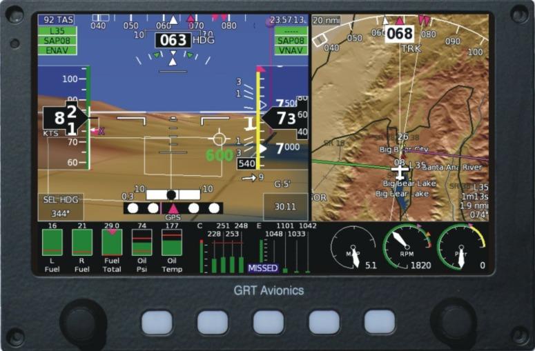
10 SPORT Installation Manual this on its map and flight plan pages. This feature is also useful for adding IFR GPS capability to the Sport system via an IFR approved GPS. Note that the only GPS functions will be transmitted via a GPS serial output, such as position, ground track, flight plan, etc, and other non-gps data, such as map details, terrian, XM weather, etc, are not displayed on the GRT EFIS screen. When the Grand Rapids Technologies Engine Information System (EIS) unit is installed in the aircraft, every engine parameter imaginable is able to be monitored through the EFIS system. The EIS module senses the desired engine or environmental data, such as exhaust gas temperature, cylinder head temperature, oil temperature/pressure, and outside air temperature, and displays it on both the EIS screen and the EFIS screen. While the EIS displays it in numerical data only, the EFIS can display data in graphical format, which is useful and easy to read during flight. One notable feature is the EGT line graph, which tracks EGT data for each cylinder over time and allows easy and instantaneous rough-engine troubleshooting. The ENG page on the EFIS is dedicated to engine and environmental parameters. Engine data can also be displayed on a portion of the primary flight display page, fully customizable in-flight according to the pilot s taste and situation. GRT strives to maintain open compatibility with third-party equipment vendors. This allows aircraft builders and pilots the freedom to choose whatever brands fit their mission and budget, as well as the flexibility for easy upgrades as technology evolves. Radios, transponders, ADS-B modules, and many other third-party units interface with the GRT Sport through serial and USB ports. Gray code output is available for transponders that require it. VOR/localizer data, traffic alerts, and in-flight weather are very common additions that are easily displayed on the EFIS screen. The addition of a second or third EFIS screen also doubles or triples the number of available serial and USB ports available, allowing use of more third-party devices. The inter-display link between EFIS screens allows data from most devices to be shared among screens for redundancy and convenience. See Section 5, the Appendix of this manual, and the Support section of grtavionics.com for information on various GRT system & third party equipment configurations. Display Unit Features & Limitations Complete PFD/Map/Engine display functionality (optional sensors required). Optional Synthetic Vision with 10 mile range with terrain, obstacles, airports, and more. Sunlight-Readable LCD displays, dimmable for night vision. Internal AHRS/Air Data computer provides critical attitude, altitude and airspeed data. Supports internal GRT GPS, external GRT GPS module, or third-party GPS. High-Integrity AHRS; Does not require pitot/static or GPS aiding. Internal world-wide database Displays Traffic Information Service (TIS) traffic. when used with Mode S transponder Interfaces to XM, ADS-B weather and ADS-B traffic Revision D 1-10
11 Interfaces to SL30/40 for display of VOR/ILS/GS and tuning pre-set radio frequencies Fully-integrated autopilot functionality or interface with third-party autopilot units Flight director Customizable split-screen views, PFD-MFD screen swap, engine page and moving map overlays Up to 5 serial ports (4 standard; fifth comes with upgraded processor) Optional ARINC 429 expansion module for full interface with Garmin panel mount GPS The serial interfaces with at least the following equipment. The list is always growing... ADS-B (Traffic and Weather) EIS Engine Monitor (all versions) GRT Autopilot Servos Single or Dual GPS Receivers (all types) Full Nav Interface with Garmin 400/500/600/700 Series Panel Mount GPS/Nav/Comm Single or Dual SL30/SL40 Deviation data from all Nav radios except those with composite outputs XM Satellite Weather CO Guardian TIS Traffic datalink (GTX 330) Zaon Traffic BF Goodrich WX-500 Stormscope Vertical Power (All Models) Tru-Track Autopilot Trio Autopilot All transponders which use serial data input TCAS Light Aircraft Avionics Primer Modern flight instrumentation systems may seem intimidating, but they can be simpler to install than their analog counterparts. This section provides some basic information for aircraft builders new to the world of electronic flight display systems. System Components & Communication 1-11 Revision F
12 Sport SX Display Unit Physical Specs Overall Size: 6.5 Sport SX Faceplate Depth of Display Unit Panel Opening Weight 7.1 wide x 5.25 high 4.75 behind panel face (approx.) 6.25 wide x 5.19 high 3.5 lbs Overall Size: 8.4 Sport SX Faceplate Depth of Display Unit Panel Opening Weight 8.7 wide x 6.47 high 4.75 behind panel face (approx.) wide x 6.33 high 4.2 lbs Sport EFIS Specifications Max Angular Rate Pitch/Roll Angles Range SX200: 200 degrees/second, all axis simultaneously. SX200A: 250 degrees/second, all axis simultaneously. Unlimited Operating Temperature Range -15 F to +160 F (-25 C to +70 C) Storage Temperature Range -25 F to +185 F (-30 C to 85 C) Maximum rate of change of temperature Long Term Reference Unlimited Accelerometer and Magnetometer (not GPS dependent) Display Max/Min Backlight Intensity Airspeed Range (Standard) Airspeed Range (High-Speed) Altimeter Range Magnetic Heading Current draw Direct sunlight-readable 800/3 nits. SX200: mph IAS SX200A mph IAS SX200: mph indicated -1,000 to +35,000 feet; Meets U.S. IFR accuracy requirements Gyro-stabilized; <5 degrees error <1 amp 1-12 Revision F
13 Sport EX/Horizon EX 7 Display Unit Physical Specs Faceplate Depth of Display Unit Panel Opening Weight 7.19 wide x 4.75 high 1.5 behind panel face (approx.) 6.25 wide x 4.38 high 1.5 lbs Sport EX AHRS/Air Data Computer Specifications Max Angular Rate Pitch/Roll Angles Range 250 degrees/second, all axis simultaneously Unlimited Operating Temperature Range -15 F to +160 F (-25 C to +70 C) Storage Temperature Range -25 F to +185 F (-30 C to 85 C) Maximum rate of change of temperature Long Term Reference Display Unlimited Accelerometer (roll and pitch) and Magnetometer or GPS (yaw) Direct sunlight-readable Max/Min Backlight Intensity Airspeed Range (Standard) Airspeed Range (High-Speed) Altimeter Range Magnetic Heading Current draw 1000/3 nits mph IAS mph indicated -1,000 to +35,000 feet; Meets U.S. IFR accuracy requirements Gyro-stabilized; <5 degrees error <1 amp 1-13 Revision F
14 A key element to designing a glass-panel installation is the communication between different components of the system, which occurs primarily through serial ports. For panels with multiple screens it is essential to consider the effect of any single device failing, including a power bus, GPS, etc., and to a lesser extent, multiple failures. Most electrical connections to the EFIS are made through d-sub connectors. These connectors provide pins for dedicated functions, such as power, ground, warning light output, etc., and other pins for serial ports. All serial ports are user-configurable to allow them to be used with a wide variety of other equipment. Each serial port consists of two pins a Transmit (OUT) and a Receive (IN) that exchange information between the display unit and a connected device such as a GPS, radio or autopilot. Some devices will only transmit data (such as a GPS), some will only receive data (such as altitude data to a transponder), and some will do both (such as autopilot servos). There are two potential limitations that should be considered when planning your serial port connections: The baud rate set for as serial port in the EFIS corresponds to BOTH the serial input and output. The type of function for an EFIS serial input does not have to match, but the baud rate must be considered. For example, serial input 1 on the EFIS could be wired to an EIS engine monitor. It would be configured for 9600 baud. Serial output 1 on the EFIS could be used to send altitude data to a transponder if it accepted data at 9600 baud. The hardware design of the serial inputs to the EFIS impose less than RS-232 standard loads, so the data provided to multiple EFIS screens can be provided by any standard RS-232 output. For example, as serial output from an external GPS can be wired to multiple GRT EFIS display units without concern for the loading the EFIS may place on this signal. The Sport SX has four serial ports, all high speed (five if it has the upgraded processor). Sport HS or WS units only have four serial ports, and Port 4 is the only high-speed port. (This is why XM Weather must be wired to Serial Port 4 when installed in a WS or HS system.) During the display unit Setup Procedure, you will use the GRT Sport Setup Guide to program the display unit and tell it which device uses each serial port and the baud rate it requires. The Sport EX and Horizon EX provide 6 serial ports, all of which are high-speed. Data is transported through the serial ports to make the devices work. A stream of serial data is like a sentence, and data packets are like the words. Data packets are transmitted in a predetermined order and frequency. This frequency is known as the baud rate. A device that communicates at a baud rate of 9600 delivers 9600 coded data packets per second in a sequence that the receiving device expects. The baud rate of the serial port in the EFIS must be configured 1-14 Revision F
15 to match that of the device. Note that when two devices share one serial port, they must use the same baud rate. Gray-Code Altitude Encoder Output (Applies to Sport SX Only) Older transponders use a binary language called gray-code to receive data from altitude encoders. Because the Sport EFIS contains an internal altitude encoder, it provides a range of pins on Connector A for gray-code output. These pins are designated on the PFD Connector A Pinout Diagram in the Appendix of this manual. Each pin has an alphanumeric code attached to it. The manufacturer of the transponder has designated the matching codes for the pins of the transponder s connector. Newer transponders, such as the Garmin GTX 327 and GTX 330, have the option to use serial data instead of gray-code, which can simplify things by cutting all this work down to one wire if you have a free serial port. USB Port In some cases other equipment may communicate with the EFIS via a USB connection. A USB port is easy to connect and transmits large amounts of data quickly. USB devices do not require you to program a baud rate. The Sport SX/EX/Horizon EX all have one USB port that may be used for one USB device, or you may attach a USB hub to run up to three devices. Software updates are also delivered to the EFIS via USB simply install the software update files onto a USB thumb drive from the GRT website, then install the thumb drive to the EFIS USB port. The EFIS will upload the files when you follow the Update instructions in the Sport Setup Guide. Physical Wiring The EFIS is supplied with a wiring harness composed of 22 gauge tefzel insulated stranded wire suited for use in any aircraft. All wires are different colors, and are terminated with a d-sub connector pin. Wires that are certain to be used, such as power and ground, are factory installed in the d-sub connector housing. The remaining wires are can be inserted into the connector for inputs that are to be used. If a wire is installed in the wrong location in the connector housing it can be removed using a d-sub pin removal tool, although this can be somewhat difficult. When routing wires it is highly desirable to allow to allow extra wire length to allow for future maintenance or alterations. When wiring an airplane it can also be useful to run spare wires to accommodate future changes. Be sure wires are never so short that they must be put under tension to allow them to be plugged. If you should need to install you own pins, information on how to crimp wires is available on the EAA s Hints for Homebuilders website, as well as written information in the publications listed at the end of this section Revision F
16 The pinout diagrams included in this manual show the function of each d-sub connector pin. NC means no connection, or a pin that should not be used. TX, or transmit, designates a Serial OUT, and RX, or receive, designates a Serial IN connection. The graphic interface diagram is provided as an example of how different devices are wired to the EFIS. The example provided uses two EFIS screens, an EIS, Garmin SL30 nav/com and GTX327 Mode C transponder, Navworx ADS-B unit, and a GRT integrated autopilot. It shows one efficient way to use the serial ports, and is based on many years of experience of our techs. Of course, this is just an example, and different third-party equipment and serial port configurations are left up to the builder and panel designer. Optional Features - (Sport EX Only) The Sport EX/Horizon EX include optional features that allow you purchase the EFIS at a lower cost, and then expand the capabilities of the EFIS in the future, usually without removing it from your instrument panel. These options can be purchased in a group at a discount, or individually as you need them. The options are: Moving Map - Includes free database updates for US territory. Worldwide database coverage is provided by Jeppesen database subscritpion. Synthetic Vision/Terrain Relief Map - 10 mile range, high-resolution forward looking synthetic vision includes terrain, runways, obstacles, waypoints, and traffic ADS-B Displays for traffic and weather on the PFD and MAP screens - Requires a connection to any ADS-B receiver that provides data in the standard GDL-90 format. Bluetooth wireless interface to the free GRT Connect Android App 3 Additional Serial Ports (3 are standard) Analog Inputs/Audio Output (See below) Basic Engine Monitoring (See below) Angle-of-Attack sensing* Touchscreen* *These options requires a hardware upgrade, requiring the unit to be returned to GRT. Analog Inputs/Audio Output - (Sport/Horizon EX only) The Sport EX/Horizon EX I includes optional analog input and an audio output. The analog inputs allow the EFIS to measure up to 4 individual voltages in the airplane that can be used by the EFIS that are commonly used for displaying trim and flap position, but may be user-defined for just about any purpose. For example, these inputs could be used to display fuel levels, fuel pressure, water temperature, or even ignition advance (if this was provided by your ignition system) Revision F
17 The audio output provides alerting when limits are exceeded, altitude call-outs on approach, traffic alerts, and much more. The audio output is wired through your intercom or audio panel. Basic Engine Monitoring Functions - (Sport/Horizon EX Only) Basic engine monitoring provides oil temperature, oil pressure, tachometer, hourmeter and flight timer. The option is provided with the sensors. These sensors are compatible with the GRT Engine Information System (EIS), to allow for a simple upgrade in the future. Other engine monitoring can be added using the optional analog inputs. (EGT and CHT monitoring can not be performed via the analog inputs due to the very small voltages generated by these probes. ) Optional Features - (Sport SX Only) The Sport SX includes a moving map, ADS-B displays, bluetooth wireless enabled, 5 serial ports and audio alerting as standard features. Synthetic vision/terrian relief map and angle-of-attack are available options. Touchscreen, basic engine monitoring, and analog inputs are not available at this time. For More Information Depending on what your mission is, you may want a simple VFR system, or an IFR system with many built-in redundancies. The GRT system enables customization for the whole range of possibilities, from simple to sophisticated, depending on the builder s desire and skill level. While this manual covers the very basics of EFIS wiring & communication and the GRT Sport-specific details, there are many very important safety aspects of aircraft wiring that we cannot even begin to discuss in this manual. The techs at GRT recommend the following sources for more information on proper aircraft avionics & electrical system design: by Bob Nuckolls is a great place to start. This manual covers everything from the very basics of electricity to the proper design and installation of sophisticated IFR-capable systems. Longtime EAA columnist Tony Bingelis s books, the series, have long been a staple of experimental aircraft builder knowledge. In addition to wiring considerations, Mr. Bingelis discusses all aspects of kitplane building, from spinner to tail. FAA Advisory Circular B provides the certified reference for safe and durable aircraft wiring techniques, though it is a bit outdated. It is available online for free download from All of the above publications are available at Amazon.com. The Experimental Aircraft Association has compiled a collection of videos called Hints for Homebuilders on its website, A quick search through these will give you valuable hints on various wiring topics, including properly crimping D-sub/Molex connector pins Revision F
18 SPORT Installation Manual Display Unit Installation SECTION 2: MECHANICAL INSTALLATION Mount the display unit(s) in the desired location in the instrument panel. The main consideration in choosing a location is the ability to view the display unit and reach its controls. Since the display is fully sunlight-readable, no consideration for shielding the display unit from sunlight is required. Be mindful of the space behind the instrument panel as well; some aircraft with tip-up canopies, for example, have canopy supports that may interfere with the back of the EFIS when the canopy is closed. See the Appendix of this manual for 6.5 and 8.4 Sport mounting templates. 1. For panel mount style display units, the use of nut plates behind the instrument panel greatly simplifies the task of installing and removing the 4 screws used to retain the display unit in the panel. #6 socket cap stainless steel screws are recommended. 2. For radio rack style display units, the #6 screws on the side of the unit (2 per side) should be used to attach the display unit to the radio rack. Remote Digital Magnetometer Installation (This section does not apply to Horizon EX.) The remote magnetometer must be placed in an area of the airplane with little or no electromagnetic interference. The cable is 20 feet long and designed to reach out to the wingtip or tail. The magnetometer is marked with an arrow pointing in the direction of flight. Mount the it with the arrow pointing forward, parallel to the centerline of the airplane. There is not a designated top of the magnetometer, so it can be turned on its side for easier mounting. The side of a wing tip rib is a simple place to put it. The arrow on the magnetometer should be parallel with the centerline of the airplane for yaw. Pitch attitude is not critical as long as it is within 60 degrees nose up or nose down. 60 up limit Longitudinal Axis 60 down limit NOTE: The most common cause of magnetic sensing error is simply magnetic disturbances near the magnetometer. This can be caused by ferrous metal (any metal that a magnet will stick to), Revision F 2-18
19 control cables, or cable carrying electrical currents, such as navigation or landing lights, being too close to the magnetometer. The magnetometer s location will be tested for interference in Section 4, after the initial boot-up checks of the Mini. Legacy Analog Magnetometer Installation for Sport SX200 Determining the location of the magnetometer requires considerable care because of the magnetometer's sensitivity to magnetic disturbances generated by the airplane. No periodic maintenance is required for the magnetometer, although it is desirable to mount it in a location that allows access to it if necessary. The most important consideration when mounting the magnetometer is choosing a location in the airplane that is away from magnetic disturbances. It is quite amazing how sensitive the magnetometer is to these disturbances, and how much error this can cause in the magnetic heading reported by the AHRS. Keep the magnetometer at least 12 inches away from any current carrying wires (such as navigation or landing light wires), and more than 18 inches from ferrous metal, such as the steel mass balance tube that is typically used in the leading edge of ailerons. Use non ferrous hardware (or even double sticky tape) for mounting the magnetometer. You can test your proposed magnetometer location prior to mounting the magnetometer itself by placing an ordinary compass at the spot. Then, Figure 2-1: Magnetometer/Display Mounting Alignment 2-19
20 SPORT Installation Manual 1. Turn on and off any electrical equipment whose wiring passes within 2 feet of the magnetometer. 2. Move the flight controls from limit to limit. 3. If the magnetometer is located within 2 feet of retractable landing gear, operate the landing gear. Observe the compass while doing each of the above. The goal is no movement, or compass movement of less than 5 degrees. If you observe greater movement, try another location. After the installation and wiring of the magnetometer and display unit(s) is complete, a more sensitive check for magnetic disturbances will be conducted. The magnetometer and the AHRS in the Primary Flight Display unit work together. For this reason, they must be oriented in the same directions, that is, the pitch, roll and yaw axes of the magnetometer and the PFD display unit which contains the AHRS need to be parallel. A standard level can be used to orient the magnetometer and display unit such that they are equal in roll, and in pitch. For yaw, the orientation of these devices should be parallel to the fuselage centerline. In cases where the magnetometer is mounted in the wing, it may be possible to orient the magnetometer parallel to a wing rib, if these ribs are oriented in the wing such that they are parallel to the fuselage centerline. This is quite practical in airplanes such as Van s RV s. Figure 2-1 illustrates this. NOTE: Magnetometer and Display Unit with AHRS must be mounted in same attitude relative to each other. Be sure to mount the magnetometer with the connector toward the rear of the airplane. Observe the label on the magnetometer to insure it is oriented correctly. Refer to the Magnetometer Installation page in the Appendix of this manual for additional installation instructions. Cooling Considerations The GRT Sport EFIS SX/EX and Horizon ES do not require external cooling. However, as with all electronic equipment, lower operating temperatures may extend equipment life. Units in an avionics stack heat each other through radiation, convection and sometimes by direct conduction. Even a stand- alone unit operates at a higher temperature in still air than in moving air. Fans or some other means of moving air around electronic equipment are usually worthwhile. Be certain that cooling air does not contain water a problem often encountered when using external forced air cooling air. A few small openings in the glare shield is usually enough to allow natural air circulation. Pitot-Static Connections The PFD display unit also contains the Air Data Computer. The ADC requires connection to the aircraft pitot-static system. Connections on the display unit take a 1/8 27 NPT male fitting. To Revision F 2-20
21 facilitate installation and removal of the display unit, quick disconnect fittings may be helpful. Connections and the entire pitot-static system must be leak tight. Refer to AC B for approved methods to achieve this. Consider placing a water trap or drain in the lowest part of the pitot-static system to prevent water from getting into the electronics. Make sure the drain is of a high enough quality that it seals completely airtight when closed. Angle-of-Attach Pressure Port Connection When equipped with the sensed angle-of-attack (AOA) option, the pitot/static block will also include a port for sensing the AOA using a dual port pitot tube. This type of pitot tube provides the pitot pressure for sensing indicated airspeed, and a second pitot pressure for sensing AOA. Typically this AOA pitot is positioned about 60 degrees down from the pitot used to sense indicated airspeed. This probe is available from several third-party sources, or may be fabricated by the builder by adding a second pitot tube, bent to point 60 degrees below the pitot used for airspeed. When constructing your own AOA pitot, it should be mounted as close as practical to the airspeed pitot. Use the appropriate tubing to make an air-tight connection between the AOA pitot and the AOA port on the EFIS. The AOA port is located between the pitot (marked P ) and the static (marked S ) ports. 2-21
22 SPORT Installation Manual SECTION 3: WIRING CONSIDERATIONS General Guidelines Wires that are certain to be used are pre-installed in the EFIS cable assembly connectors. Optional connections to the EFIS are not installed in the D-sub connectors at the factory, however, colored aviation-grade wires with pre-installed D-sub connector contacts are included for these connections. The cable description diagram includes recommended wire colors for each connection to the EFIS components. When routing the wiring, the following guidelines should be considered: Good practices for physical installation of the wiring should be followed, such as grommets where wires pass through sheet metal, considering for chaffing and interference with moving mechanisms, etc.. Cable lengths should include enough extra length to allow for servicing the equipment. For example, the cables which plug into the display unit should be long enough to allow them to be connected to display unit with the display unit not installed in the instrument panel. In general, routing of the wiring is not critical, as the EFIS is designed to be tolerant of the electrical noise and other emissions typically found in aircraft. Some consideration should be given to avoid routing wires near antennas, or other locations that could impart high levels of electromagnetic signals on the wiring. The checkout procedures outlined in Section must be completed to verify the EFIS is not affected by radio transmissions on any frequency. Consider the effects of individual component failures in the design of the system as a whole to create redundancy where necessary. Power Connections The display units each include 2 isolated power input connections. This allows redundant power sources, such as a main and secondary bus. The display units consume approximately 1 amp, making even a 2 Amp-hour gel cell a suitable backup power source.. The configuration of the power supplied to the display unit(s) is left to the installer. Considerations such as the number of power buses, the desire or not to supply one piece of equipment with power from redundant buses (which in theory allows the possibility of one device affecting both buses), the configuration of the electrical system with respect to backup equipment, and so on, may dictate the best configuration for a particular airplane. Revision F 3-22
23 No provision is included within the display units for a power switch. If a power switch is desired for the EFIS, the +12V power should be controlled with the switch (not ground). The display units include internal thermally-activated fuses. This protects the equipment from internal electrical faults. Power supplied to the EFIS must pass through a fuse or circuit breaker. It should be sized to allow at least 1.5 amps per display unit, with a maximum rating of 5 amps. The AHRS and display units monitor all of their power inputs, and alarms are available to annunciate the loss of any power source that was provided and is expected to be working according to the General Setup menu. The majority of the current flow into the display unit will occur on the bus with the highest voltage. It is desirable to have the display units and AHRS off during the engine start if all of the buses which power them are used for supplying power to the engine starter. This maximizes the current available for the starter, and prevents undesirable voltage fluctuations from being applied to the display unit when it is booting up. Ground Connections The cable assembly provided includes 22 gauge wire for the ground return of the display units. This will result in a voltage drop of about V/foot, which is acceptable for wire lengths up to 10 feet. Magnetometer Wiring Typically, the magnetometer cable supplied with the EFIS will not have a D-sub connector installed on magnetometer cable end. This makes it easier to route this cable through the airplane. After the cable has been routed, the wires can be cut to length if desired, although new D-sub pins would need to be installed. If the wires are not cut, inspect the D-sub connector pins to verify they have not been damaged. Insert the indicated wire color into the appropriate D-sub connector housing hole according to the Sport Connector Definitions diagram. If desired, the crimp-type D-sub connector can be replaced with a solder-type connector. All magnetometer connections are made directly to the mating display unit with internal AHRS. This wiring includes the power connections necessary for the magnetometer to operate. SX200A Only: The digital magnetometer serial output may be shared between any number of the Mini-X, Mini-AP, and any Adaptive AHRS. SX200 Legacy Only: Each AHRS and magnetometer pair is calibrated together at the factory for optimal accuracy, and thus this paring should be maintained for best performance. Multiple AHRS Inputs - (Sport EX/Horizon EX Only) The Sport EX/Horizon EX is capable of receiving two sets of primary AHRS data. Typically one set of primary AHRS data would come from its internal AHRS (Sport EX), and a second set may be provided through a serial port connection to an external AHRS. Primary AHRS data is required to 3-23
24 SPORT Installation Manual provide normal autopilot performance when the EFIS is wired to autopilot servos. Providing the EFIS with multiple attitude sources allows for automatic cross-checking of the attitude data. Future growth: The EFIS will use Backup AHRS data to perform cross-checking between all of attitude sources provided to it. Backup AHRS data is data provided to the EFIS via an inter-display unit link, and may include some latency, and thus can not be relied upon for normal autopilot performance. Backup AHRS data can be selected to drive the EFIS screens. When this is selected, the EFIS will continuously display Backup Attitude on the PFD screen to alert the pilot that this data is a duplicate of the data provided by the backup source. Backup attitude data allows the EFIS to more reliably choose the best AHRS when the cross-check detects a mis-compare. Loss of GPS Data While it is expected that the EFIS will be provided with GPS data to provide accurate navigation information, it is possible that all GPS data could be lost. If this were to occur when in flight,the EFIS will dead-reckon from its last known GPS position. Due to varying winds and sensor errors, the EFIS system position will degrade in accuracy over time. The intent of the dead-reckoned system position is to provide approximate position information so that the pilot has time to implement other means of navigation, such as visual observations, VOR, etc. Specific Equipment Interconnect Details Most equipment shares information with the EFIS via a serial port connection. Each serial port in the EFIS that is wired to another device must be configured so the EFIS knows what it has been connected to. This is accomplished via the Set Menu, General Setup menu. Each serial port is listed, and entries are provided to allow configuring them for a wide variety of functions. Since all serial ports on the Sport SX, Sport EX, and Horizon EX are high-speed ports, capable or receiving data at 115,200 baud, any serial port can be used for any function. Detailed instructions and wiring information for connecting to specific other avionics equipment, along with EFIS pinout information, are provided in Section 5 and the Appendix of this manual, and are provided as Equipment Supplements on the website. Depending on the other equipment installed in the airplane, switches may be necessary or desirable for some functions. For example, a switch to allow the autopilot to be controlled by the EFIS, or directly from the GPS, allows the GPS to control the autopilot in the event the display unit which normally commands the autopilot is not functioning. Warning Light Output A warning output is provided on the d-sub connector to drive an external warning light. This output provides a path to ground when active, thus the indicator should be wired with one of its terminals to aircraft power, and the other to this output. The maximum current that can be controlled by this output is 0.2 amps. Revision F 3-24
25 SPORT Installation Manual SECTION 4: Initial Checkout, Basic Configuration Settings, and Calibration Display Unit Check Out 1. Apply power to the display unit. The LCD may flicker, and within 20 seconds, the display should show the accept page if on the ground. (If in-flight, the accept page will not be displayed. ) 2. If multiple power buses connect to the display unit, apply power from each bus individually to test. Basic Configuration Settings The basic configuration settings can be made in any order. The default settings will usually allow most basic functions, such as the AHRS and GPS, to function, but this is not true for serial ports. Configuring Serial Ports When wiring the airplane it was likely that serial ports were used to send and receive information to other equipment. Each serial port, input and output, must be configured to allow successful communication with these devices. This configuration includes setting both the function, and the buad rate. A serial counter is provided to show when data is being detected at a serial input to the EFIS to help validate a new installation. The serial ports can not be configured. The configuration data is accessed by finding the Set Menu softkey that appears on the PFD, MAP and Engine pages. Pressing this button bring up the Settings Menu. Categories, and settings within them, are selected by rotating the knob to choose an item, and pressing the knob to enter or change a setting. Serial port configuration for various devices are described in equipment supplements on the GRT website, and in the Sport Setup Manual. Once all settings are complete, the settings should be backed up to a USB memory stick using the User Setting Backup function on the Display Unit Maintenance set menu. This will allow you to restore these setting if they every become altered, and also allows you to review the settings when away from the airplane by viewing the backup file with a text editor. Required setup for the internal GPS The internal GPS must be designated as GPS1, GPS2, or No (not used), to specify with of the two possible GPS sources the EFIS may use. No specifies that the internal GPS will not be used. For external GPS inputs, the serial port setup specifies if a particular input is configured as GPS1 or GPS2. The following user setting defines how the internal GPS is to be used. Internal GPS: None / GPS1 / GPS2. (Applies to Sport EX only. Accessed via the Set Menu, General Setup submenu) (Factory default is GPS1). This setting is used to assign the internal GPS to one of the two EFIS GPS inputs. If None is selected, up to 2 external GPS inputs may be wired through the serial inputs and/or from data transmitted over the inter-display link from another GRT EFIS. Revision F 4-25
26 At least one GPS should be connected to the EFIS. Only one GPS source (internal or external, can be assigned to GPS1, and only one GPS source may be assigned to GPS2.) Sport SX Internal GPS Settings The internal GPS provides serial data at 9600 baud in the NMEA0183B format. The output from this GPS is wired to pin 32, may be shared with all GRT EFIS display units as desired, as well as at least two other devices, such as an ELT, transponder, etc. If these other devices impart too much load on the serial output, the signal level will be reduced and some or all of these device will receive no data. Sport EX - Trig TT22 Port The Sport EX provides an A/B port for direct connection to the Trig via its A/B port. If this port is wired to the Trig TT22, the following should be set. This setting is accessed from the set menu, general setup submenu: TT22 A/B Port: (On/Off) Default is off. Turn this on if a Trig TT22 is wired to the Sport EX. This setting should be off is a Trig TT 22 is wired to the EFIS via a serial port using the GRT-Trig adapter. Sport EX - Required setup for the internal AHRS The Sport EX is capable of receiving two sets of primary AHRS data. Typically one set of primary AHRS data would come from its internal AHRS, and a second set may be provided through a serial port connection to an external AHRS. Primary AHRS data is required to provide autopilot functionality when the EFIS is wired to autopilot servos. Future growth: The EFIS will use Backup AHRS data to perform cross-checking between all of attitude sources provided to it. Backup AHRS data is data provided to the EFIS via an inter-display unit link, and may include some latency, and thus can not be relied upon for normal autopilot performance. Backup AHRS data can be selected to drive the EFIS screens. When this is selected, the EFIS will continuously display Backup Attitude on the PFD screen to alert the pilot that this data is a duplicate of the data provided by the backup source. A user setting is provided to allow for designating if the internal AHRS is to be used, and if so, whether it is identified as AHRS1 or AHRS2. This setting is accessed from the set menu, general setup menu, and appears as follows: Internal AHRS : No/AHRS1/AHRS2 - Normally this is configured to AHRS1. If the display unit is wired to an external AHRS, the serial port for this AHRS would be configured as AHRS2. If two sets of external AHRS data is provided to the EFIS, this setting must be set to No. Sport EX - Defining Magnetometer Connections Since the adaptive AHRS does not require a magnetometer, a setting is provided to specify if one has been connected to the AHRS. This allows the EFIS to detect if an installed magnetometer has 4-26 Revision D
27 SPORT Installation Manual stopped providing data. A setting is provided for each of the two possible AHRS connections. This setting is provided via the set menu, general setup submenu. AHRS(1/2) Has Magnetometer: Yes/No/Auto (default is auto) - Set to match your installation. If it is unknown, use the Auto setting until you determine if one has been connected. The EFIS will generate a warning if an AHRS specified to have a magnetometer provides data showing that no magnetometer data is being received by this AHRS. AHRS/Air Data Computer Test Note: All sections related to AHRS/Air Data Computer, and magnetometer, apply only to the Sport SX200, and Sport EX, since these models include an AHRS/Air Data Computer, and may include an optional magnetometer. 1. Apply power to display unit with internal AHRS. 2. Proper operation of the AHRS and magnetometer is indicated as follows: a. The display unit shows altitude and airspeed tapes. b. Attitude and heading data appears on the screen at the completion of the alignment period (typically less than 2 minutes). c. No "ATTITUDE FAIL" message is shown on the PFD screen. d. No failure messages are listed in the status page (accessible from the "Status" softkey on the PFD screen). 3. Select the Set Menu from the softkeys, and select the AHRS Maintenance page. 4. Verify AHRS communications status is valid, and AHRS status is OK. Verify the AHRS is receiving serial communications from the display unit by observing that no data fields are grayed out. 5. Verify the PFD screen shows HDG next to the heading box at the top-center of the screen. This indicates that it is receiving valid heading data from the magnetometer. Revision F 4-27
28 Setting Instrument (AHRS) Orientation This is a coarse setting to account for angled instrument panel installations. You will fine-tune the instrument orientation again in flight after validating the location of the magnetometer (if installed). 1. Access Set Menu > AHRS Maintenance. Scroll to Set Instrument Orientation. 2. Enter the offset in degrees for each axis. Positive corrections correspond to right roll, pitch up, and right yaw. See example sketches below (not to scale): Instrument Panel Tilt 20 Pitch Down = -20 Pitch Offset Longitudinal Axis EFIS Tilted toward Pilot 15 Right Yaw = +15 Yaw Offset Longitudinal Axis line drawing used with permission from Sport Performance Aviation, LLC 4-28 Revision D
29 Magnetometer Location Validation 1. Park the aircraft on a level surface and start the engine. 2. Press any button on the EFIS display to bring up the soft key labels. Press SET MENU soft key, then scroll to and select AHRS Maintenance. Locate Magnetic Heading field on this screen. NOTE: Do not use the heading data shown on the heading tape on the PFD for calibration because this is a composite reading of several other pieces of information. The Magnetic Heading field contains instantaneous data on magnetic heading only. 3. Observe the Magnetic Heading and verify it does not change by more than +/- 2 degrees while doing the following: a. Turn on and off any electrical equipment whose wiring passes within 2 feet of the magnetometer. b. Move all flight controls from limit to limit. c. Shut down the engine and observe the heading while the engine is not running, noting any difference. d. For aircraft with retractable landing gear: If the magnetometer is located within 2 feet of retractable landing gear, support the aircraft using proper jacking equipment, then repeat Step 1 while operating the landing gear. e. If greater than +/- 2 degree change is noted, either relocate the magnetometer or the offending wiring or metallic materials. Recheck. The most common cause is simply magnetic disturbances near the magnetometer. This can be caused by ferrous metal (any metal that a magnet will stick to), control cables, or cable carrying electrical currents, such as navigation or landing lights, being too close to the magnetometer. If there is any doubt about a location, try moving the magnetometer to another location. Use tape or other temporary means to hold it in place, roughly aligned with the orientation of the AHRS, and repeat the test. Wiring Problems - Sport SX200 (Legacy) 1. Some wiring problems will be detected by the AHRS built-in-test functions. The will result in an AHRS Attitude Fail Message, and an "AHRS: Magnetometer X, Y or Z-Axis Failed" message on the status page that is accessed by the STATUS button from any page. If this message is present, the wiring to the magnetometer should be checked Revision D
30 SPORT Installation Manual 2. It is also possible that no built-in-test failure is reported, but the wiring is still incorrect. This can occur if the magnetometer X, Y, Z inputs are swapped. To check for this, point the airplane at various directions listed in the table below, with the magnetometer in an approximately level position (it may need to be removed from the airplane and held by hand). Use the AHRS Maintenance page to observe the "Magnetometer X, Y, Z Raw Data". The following should be observed: * The raw data readings will appear to shift left and right on the screen once per second, as the signs change for a brief moment. This is normal, and the brief sign changes should be ignored when using this table of the expected readings. ** The Z Raw data will be greatly influenced by where on the earth the test is performed. Positive values will be observed in the northern hemisphere and negative values in the southern hemisphere. Set Final Magnetometer and Instrument Orientation Once the chosen magnetometer location is verified to have acceptable levels of interference, set the orientation of the magnetometer. 1. Go to Set Menu > AHRS Maintenance > Set Magnetometer Orientation. Answer the prompts on the screen to begin automatic orientation of the magnetometer. For maximum accuracy, this procedure should be performed with the ambient temperature is in the range of deg F. 2. When the final instrument and magnetometer orientations are set, perform the Fine Magnetometer Calibration, described in the next section. Check Uncorrected Magnetic Heading While the calibration procedure can remove errors as large as 127 degrees, accuracy is improved if the location chosen for the magnetometer requires corrections of less than 30 degrees. To check the accuracy of the uncorrected magnetic heading: 1. Scroll to Magnetometer Calibration on the AHRS Maintenance page and select it. 2. While on this page, rotate the airplane 360 degrees. A red graph will appear on this page showing the calculated errors. If errors of greater than 30 degrees are observed, see section 4.3 to troubleshoot. Revision F 4-30
31 Magnetometer Calibration Procedure The magnetometer must be calibrated before the first flight of the aircraft. Magnetometer calibration is required to achieve accurate magnetic heading readings. This calibration corrects for errors induced by magnetic disturbances local to the sensor, such as ferrous metal objects. NOTE: The AHRS will not allow magnetometer calibration to be initiated if the airspeed is greater than 50 mph to prevent inadvertent selection while in flight. If calibration is successful, the existing calibration data (if any) will be replaced with the new corrections. The Magnetometer Calibration page will help guide you through this procedure with its on-screen menus and prompts. Note: Before performing this procedure, be sure the AHRS orientation and magnetometer orientation have been set. If these are not performed, the magnetometer calibration will not result in accurate magnetic headings. 1. Point the aircraft to magnetic north, in an area without magnetic disturbances, such as a compass rose. A simple means of pointing the airplane toward magnetic north is to taxi the airplane slowly and use the GPS ground track to determine when you are taxiing in a magnetic north direction. Make small corrections to the direction of travel of the airplane, and continue to taxi for several seconds for the GPS to accurately determine your ground track. The GPS cannot determine your track unless you are moving. 2. After the aircraft is positioned accurately, turn ON the GRT Sport. (If it was already on, then turn it OFF, and then back ON again.) 3. Allow at least 1 minute for the AHRS to fully stabilize. 4. Press any button on the EFIS display to bring up the soft key labels. Press SET MENU soft key,, then scroll to and select AHRS Maintenance. Scroll to and select Magnetometer Calibration field on this screen. 5. Press Start soft key. 6. The first question is Are you sure? Press YES if you are sure. 7. Verify the airplane is still pointed to magnetic north. Answer the question Are the aircraft, AHRS, and magnetometer pointing to magnetic north? with YES. A message will appear at the bottom of the screen indicating the system is waiting for the gyros to stabilize. 8. As soon as the message Calibration in Progress is displayed (within 15 seconds), rotate the aircraft 360 degrees plus 20 degrees in a counter-clockwise manner (initially towards west). The airplane does not need to be rotated in place, but simply pulled or taxied in a circle. The 4-31 Revision D
32 airplane must be rotated completely through 360 degrees, plus an additional 20 degrees past magnetic north, within 3 minutes after initiating the calibration. The airplane should be rotated slowly, such that it takes approximately 60 seconds for the complete rotation. 9. If calibration is successful, the AHRS will re-start itself automatically, and begin using the corrections. While re-starting, the AHRS will not provide data. This will result in the AHRS data disappearing from the display unit for about 10 seconds. 10. If calibration is unsuccessful, one of two things will happen. In either case, the calibration procedure must be repeated. a. If the airplane is rotated too rapidly, the calibration will not end after the airplane has been rotated 380 degrees. b. It will exit calibration mode, and will show Calibration INVALID - Maximum correction exceeded if a correction of greater than 127 degrees is required. (Invalid - OVERLIMIT will be displayed on the AHRS maintenance page next to the Magnetometer Calibration field.) A correction of greater than 127 degrees can be caused by incorrect mounting of the magnetometer, or location of the magnetometer too close to ferrous metal in the aircraft, or starting with the airplane not pointed toward magnetic north or magnetometer wiring errors. The accuracy of the magnetometer calibration can now be verified. 11. Point the airplane toward magnetic north. 12. Turn ON the AHRS (if already ON, turn it OFF, and then back ON). 13. Verify the AHRS (on AHRS Maintenance page) shows a heading close to north. (Small errors are likely to be a result of not positioning the airplane to the exact heading used during magnetometer calibration.) 14. Select the Magnetometer Calibration page. (Do not activate the calibration this time.) 15. Rotate the airplane through 360 degrees, and inspect the Calculated Error graph (the red line) drawn on the screen. The magnetic heading errors should be less than 5 degrees, and can typically be reduced to about 2 degrees. Accurate magnetic heading is required for the AHRS to display accurate heading data, and to allow accurate wind speed/direction calculations. The graph will also show the correction stored in the AHRS as a green line. The green line will be within the +/- 30 degree range if the magnetometer was mounted in a good location, and was mounted accurately with respect to the AHRS Revision D
33 The status of the magnetometer correction data is indicated by the field next to the Magnetometer Calibration setting on the AHRS Maintenance page. If the field has the message Change to open page, then no valid data is stored within the AHRS and it must be recalibrated. If the field says Valid, it means that the data is present. Keep in mind that the accuracy of this data is not assured because it is dependent on how carefully the user performed these steps. The calibration data should be cross-checked with reliable ground references such as a compass rose or runway headings before flight. Congratulations! Magnetometer calibration is now complete. Measuring the Accuracy of the Magnetic Heading The accuracy of the magnetic heading can be easily observed while taxiing and comparing the magnetic heading displayed on the AHRS maintenance page, to the gps groundtrack. The difference between them is the heading error in that direction. This can also be observed on the PFD screen, although the heading data on this screen is slaving the yaw gyro, and thus will respond slowly to the difference between the displayed heading and the the magnetometer heading. When using the PFD screen, the best technique is to point the airplane in the direction to be tested, wait at least 20 seconds, or until the heading is not changing, and then taxi until the ground track is stable on the PFD also. The difference between them is the magnetic heading error. If it is excessive, the fine magnetometer calibration should be repeated. How accurate should the magnetic heading be? Achieving highly accurate magnetic heading requires that the magnetometer be installed in a good location on the airplane, and the AHRS be mounted accurately. Due to the steep angle of the earth s magnetic fields (only about 20 degrees off vertical), the attitude data from the AHRS must be used to process the magnetic field data from the magnetometer, and for every degree of attitude error, 3 degrees of heading error will be induced. Heading error of less than 5 degrees are not normally apparent in normal flying, but errors this large will cause the winds calculated by the EFIS to be inaccurate. For every 1 degree of heading error, 1.7% of the forward speed of the airplane will be falsely reported as a cross-wind. Thus, with only a 5 degree heading error, an airplane flying at 100 knots will show a false crosswind of 8.5 knots. Sport EX - Basic Engine Monitoring Required Settings When using the basic engine monitoring function option that is part of the Sport EX, the following settings must be made to allow for correct readings. These settings are accessed using the Set Menu, General Setup, and are located just below the serial port settings Revision D
34 TachP/R - The TachP/R setting must be set to match the number of pulses per revolution of the engine provided by the tachometer connection. The following table below shows the most common settings. Pulses per Revolution Type Use Equivalent EIS Tach P/R Setting cylinder 4-stroke engines with magneto cylinder 4-stroke engine with magneto 1 2 Rotax 2-cycle engine - Point-Style Ignition 2 5 Jabiru 4-cylinder (s/n 22A2662 and older) 5 6 Jabiru 4-cylinder (s/n 22A2663 and newer) 6 6 Jabiru 6-cylinder 6 6 Rotax 2-cycle engines with CDI ignition 6 6 HKS cylinder 4-stroke with magneto cylinder 4-stroke with magneto cylinder 4-stroke with magneto 19 Tachometer Sensitivity - (Low/High) The tachometer input includes a sensitivity adjustment. The Low sensitivity setting is best for most h tachometer connections as it provides the greatest amount of filtering and tolerance of noise on the tachometer signal from the engine. The "High sensitivity setting is best for connections to electronic ignition systems that provide a 0-5V pulse output. Since less filtering is provided when the high sensitivity setting is used, it should not be used unless required. Note: The tachometer input can tolerate signals of 200V or greater, regardless of the TachSen setting. Caution: Accurate tachometer readings should be verified by another tachometer source, such as an optical tachometer. Attempting to fly with insufficient engine power could be dangerous. Oil Pressure (150/80) - Sets the oil pressure sensor range that has been wired to the EFIS. This setting defaults to 150. Caution: Using an 80 psi sensor with this setting as 150 will cause the displayed oil pressure to be twice actual pressure Revision D
35 SPORT Installation Manual SECTION 5: EQUIPMENT INTERCONNECT DETAILS Introduction This section contains information for wiring some of the most popular brands and models of avionics to interface with the GRT Sport. If your specific unit is not listed in this manual, please check the Support section of our website or contact GRT tech support at (616) for more information. After initial installation and wiring of all the components, use the GRT Sport Setup Guide to program limits, baud rates and preferences into the EFIS. Serial Ports The serial ports listed in this section are general suggestions. You may use any serial port with baud rates compatible with the equipment you want to connect. (NOTE: For Sport HS units with the original processor, serial port 4 is the only serial port that will support GRT XM Weather.) Common Equipment Wiring Details NOTE: Refer to the latest revisions of the installation manuals of each third-party component to ensure correct wiring information. Transponders: The EFIS can provide altitude encoding information for most transponders, including Garmin GTX327 and GTX330. Gray code outputs are provided for transponders that require this format (see pinout diagram in Appendix A). Newer transponders, such as the Garmin GTX327 and GTX330, may use either serial output or Grey code. Radio Tuning: The EFIS has the ability to load the Garmin SL30 and SL40 radios with frequency pre-sets to allow convenient selection of these frequencies from the front panel controls of the radio. For the SL30, the EFIS can also tune the navigation radio. This data is transmitted to the radio via an RS-232 serial output from the EFIS display unit. Display of Navigation Data from the SL30: The EFIS provides an HIS and other functions that display and use the VOR bearing data provided by the SL30 Nav/Com. Localizer and glide slope deviation data is also displayed on the EFIS from this radio. This data is transmitted to the radio via an RS-232 output from the EFIS display unit. Multi-Display Unit Considerations: Although the navigation data from the SL30 is communicated to other display units via the inter-display serial data connection, allowing this data to appear on all display units, it is preferable to connect the serial data output from the SL30 to two display units independently. This allows the SL30 navigation data to be displayed in the event one display unit is not functional. One serial data output from the SL30 may be connected to multiple display units. Only one serial data output TO the SL30/SL40 is provided, but in this case, redundancy is not an Revision F 5-35
36 Unit EFIS D-Sub Pin Function Device D-Sub Pin Notes Garmin GTX Serial Output 2 Connector 3721, Pin 19 Provides altitude encoding data to Transponder Garmin GTX Serial Output 2 33 Serial Input 4 Connector 3721, Pin 24 Connector 3721, Pin 25 Provides altitude encoding data to Transponder Receives TIS data from Transponder External GPS 30 Serial Input 1 Varies; RS-232 Serial Data Out Use RS-232 Serial Out from GPS unit Garmin SL40 37 Serial Output 4 Pin 10 of 15-pin connector For tuning radio through EFIS. Only one display unit may provide this connection. Garmin SL30 37 Serial Output 4 33 Serial Input 4 Pin 4 of 37-pin connector Pin 5 of 37-pin connector For tuning radio through EFIS. Only one display unit may provide this connection. Provides navigation data to EFIS. May be connected to multiple display units. TruTrak Autopilot 34 Serial Output 1 GPS Serial Data Input Output from EFIS emulates NMEA0183B serial data to control autopilot. issue. If the display unit that provides the tuning data to the SL30/SL40 is not operational, the radio would simply be tuned by its front panel controls. External GPS: The EFIS can accept and display GPS data, including flight plans, from other GPS sources such as Garmin GNS430/530 and GPSMAP496. Providing EFIS Internal GPS Data/Active Waypoint to External Devices: Sport SX - When equipped with the optional internal GPS, serial input 3 is wired within the EFIS to its internal GPS. This will cause serial output data to be present on this EFIS serial input, which may be wired to other devices that require GPS data. No flight plan or active waypoint data is provided. Sport EX - Configuring any serial output to Autopilot-NMEA 0183 will provide NMEA0183 GPS data including the active waypoint. The flight plan will not be transmitted. 5-36
37 Optional Dual Serial Inputs to Autopilot: A switch may be installed to allow coupling the autopilot to the GPS in the event the display unit that normally controls the autopilot is not functional. This switch is wired to select between the EFIS autopilot output and the GPS serial data output. This switch should remain in the EFIS position unless the display unit that provides the autopilot output is not functional. When the switch is in the GPS position, the autopilot will follow the GPS flight plan only, and will not respond to EFIS autopilot mode selections such as HDG and others. See or Equipment Supplements on the website for instructions on how to program the EFIS to communicate with each of the third-party units listed in this section. 5-37
38 SPORT Installation Manual Appendix: Mounting, Wiring & Interface Diagrams Contents Appendix: Mounting, Wiring & Interface Diagrams SPORT EFIS SPORT EFIS...40 Mounting Template...40 External Module Footprint and Mounting Holes...41 Magnetometer Installation Notes...42 Sport SX Internal GPS Diagram (Sport SX only)...43 Sport SX200A (Adaptive AHRS) Connector A Pinout Diagram...44 Connector A Pinout Diagram, Legacy Model SX Magnetometer - Digital and Analog (Legacy)...46 Sport SX200A - Connector A - Suggested wiring for a dual-screen system...47 Sport SX200 (Legacy*) Connector A -Suggested wiring for a dual-screen system...48 Sport SX100 Connector A Pinout - Suggested wiring for a Multi-Screen System...49 Sport EX/Horizon EX - Connector A Pinout Diagram...50 Sport EX/Horizon EX - Connector B Pinout Diagram...51 Angle of Attack (AOA) Installation and Calibration...52 Sport EX Basic Engine Monitoring Wiring...53 Sport EX - Common Tachometer Connections...54 Dual Sport SX200 Interconnect Diagram Example...55 Trim/Flap Position Sensor Wiring...56 Revision E A-38
39 8.4 SPORT EFIS Mounting Template Note: Depth of display unit is approx. 5 beind the panel face. Allow additional 3.5 to 4 behind display unit for wiring and pitot/static connections Panel cutout x 6.33 (This allows for a small clearance each side) Use No. 6 mounting screws. All dimensions in inches. NOT TO SCALE. 8-4 Sport Template.pdf Rev D 24-Aug-2014 A-39 Revision F
40 SPORT Installation Manual Note: Depth of display unit is approx. 5 beind the panel face. Allow additional 3.5 to 4 behind display unit for wiring and pitot/static connections Panel cutout 6.24 x 5.19 (This allows for clearance on each side) Use No. 6 screws for mounting. All dimensions in inches. NOT TO SCALE. 6.5 SPORT EFIS Mounting Template Sport Template.pdf Rev D 24-Aug-2014 Revision F A-40

41 External GPS module RAIM GPS module ARINC module Magnetometer Notes: Drawing shows height of module mounting platform only. GPS and ARINC modules are 9/16 taller than mount. Allow an extra 3 above ARINC module for D-sub connector. External Module Footprint and Mounting Holes Module Dimensions Rev A.cdr A-41 Revision F
Installation Manual. Caution: Preliminary. Due to software development occurring at this time, this manual may contain inaccuracies and omissions.
 Installation Manual Caution: Preliminary Due to software development occurring at this time, this manual may contain inaccuracies and omissions. Manual Version: Preliminary Date: 10/18/04 Grand Rapids
Models HX, HS & WS. Installation Manual
 GRT HORIZON Models HX, HS & WS Installation Manual Rev. A February 2009 Grand Rapids Technologies, Inc. 3133 Madison Avenue SE Wyoming MI 49548 616-245-7700 www.grtavionics.com INTENTIONALLY BLANK GRT
Safe-Fly 2020 ADS-B Compliant GPS Module with Serial data Combiner/Expander
 Safe-Fly 2020 ADS-B Compliant GPS Module with Serial data Combiner/Expander Revision E 6/9/2017 GRTAvionics.com 1 Table of Contents Revision History...3 Description...4 Compatibility...4 Use with Non-Compatible
10.4 HXr EFIS. GRT Avionics. (616) fax (616) above, beyond.
 fax (616) above, beyond.") Grand Rapids Technologies, Inc. 10.4 HXr EFIS The large screen EFIS for your experimental airplane. Insets...Preserving the View One look at the HXr and you sense the situational awareness provided by
Grand Rapids Technologies, Inc. 10.4 HXr EFIS The large screen EFIS for your experimental airplane. Insets...Preserving the View One look at the HXr and you sense the situational awareness provided by
EFIS Horizon Cable Description
 EFIS Horizon Cable Description Dual Display Unit EFIS System Dual AHRS/Air Data Computer March 1, 2004 Rev A Grand Rapids Technologies, Inc. Revision History Rev A - 3/1/04 Initial Release Overview This
Revision A 03/31/2017 GRTAvionics.com. Serial Combiner/Expander
 Quad Serial data Combiner/Expander Revision A 03/31/2017 GRTAvionics.com 1 Table of Contents Revision History...3 Description...4 Compatibility...4 Use with Non-Compatible GRT and other systems...4 Serial
GRT External GPS Modules Equipment Supplement
 GRT External GPS Modules Equipment Supplement 30-May-2013 Table of Contents Section 1: Introduction 1.1 About GRT GPS modules...... 3 1.2 Data Port and Hardware Requirements 3 Section 2: Installation &
Safe-Fly 2020 ADS-B Compliant GPS Module with Serial Data Combiner/Expander
 Safe-Fly 2020 ADS-B Compliant GPS Module with Serial Data Combiner/Expander Revision M 8/03/2018 GRTAvionics.com 1 Table of Contents Revision History... 3 Description... 4 Compatibility... 4 Use with Non-Compatible
Dual Electronics XGPS170 ADS-B Receiver Equipment Supplement
 Dual Electronics XGPS170 ADS-B Receiver Equipment Supplement 3 9-Jul-2014 Revision Notes Revision Date Change Description A 17-Jun-2013 Initial Release A1 19-Jun-2013 Corrected error in Section 4 regarding
EFIS Horizon Display Unit Connector Definitions
 EFIS Horizon Display Unit Connector Definitions June 7,2004 Rev D Grand Rapids Technologies, Inc. Revision History Rev C - Changed naming convention to +Left/+Right and +Up/+Down for loc/gs inputs. No
EFIS Horizon Cable Description
 EFIS Horizon Cable Description Single Display Unit Jan 23, 2004 Rev C Grand Rapids Technologies, Inc. Revision History 12/15/03 Initial Release Rev B - General Updates Rev C - 1/23/04 - Changed Red/White
AFMS, Garmin G5 AML STC Rev. 3 Page 2 of 10
 LOG OF REVISIONS Rev Page Description Date of Approval FAA Approval 1 All Original Issue 7/22/2016 Robert Murray ODA STC Unit Administrator 2 All Added information regarding G5 DG/HSI 4/28/2017 Robert
The BOM [Broadcasting Outer Module]
![The BOM [Broadcasting Outer Module]](/thumbs/91/106681333.jpg "The BOM [Broadcasting Outer Module]") Avionics Reimagined The BOM [Broadcasting Outer Module] The first and only ALL-IN-ONE AVIONICS SUITE Distributed by: Adams Aviation Supply Co Ltd mail@adamsaviation.com www.adamsaviation.com BOM (Broadcasting
Avionics Reimagined The BOM [Broadcasting Outer Module] The first and only ALL-IN-ONE AVIONICS SUITE Distributed by: Adams Aviation Supply Co Ltd mail@adamsaviation.com www.adamsaviation.com BOM (Broadcasting
V-Speed Auxiliary Display System. External AoA Indicator For Dynon and GRT EFIS Systems. Installation and Application Guide. Figure 1-1.
 Vx Aviation www.vx-aviation.com V-Speed Auxiliary Display System External AoA Indicator For Dynon and GRT EFIS Systems Installation and Application Guide 1. Features Figure 1-1. V-Speed ADS Displays Angle
FAST STACK PRO-X HUB
 FAST STACK PRO-X HUB INSTALLATION MANUAL - Rev A Approach Fast Stack 301 Airport Road 7040-9110 Park Rapids, Minnesota 56470 USA Rev. A Feb. 2010 Tel: 218-237-7825 Fax: 218-237-4426 www.approachfaststack.com
EQUIPMENT INSTALLATION MANUAL. for the GDC59 CONVERTER P/N
 EQUIPMENT INSTALLATION MANUAL for the P/N 1095-4000-01 DAC International 6702 McNeil Drive Austin, TX 78729 Copyright 2009, DAC International. All rights reserved. Rev IR Page 1 of 17 RECORD OF REVISIONS
GRT Vision Addendum to the GRT Remote App User Manual 08/19/2015
 GRT Vision Addendum to the GRT Remote App User Manual 08/19/2015 Also refer to the GRT Remote App User Manual available at: http://www.grtavionics.com/grt%20remote%20app.pdf GRT AVIONICS, INC. 1 GRT VISION
Microair Avionics Pty Ltd Airport Drive Bundaberg Queensland 4670 Australia Tel: Fax:
 Microair Avionics Pty Ltd Airport Drive Bundaberg Queensland 4670 Australia Tel: +61 7 41 553048 Fax: +61 7 41 553049 e-mail: support@microair.com.au About This Document This manual describes the various
CHAPTER 34 - NAVIGATION AND PITOT-STATIC SYSTEMS TABLE OF CONTENTS
 NAVIGATION AND PITOT-STATIC SYSTEMS 34-00 General 1 FLIGHT ENVIRONMENTAL SYSTEMS 34-10 Pitot-Static - Serials w/o Perspective Avionics 1 Pitot-Static - Serials w/ Perspective Avionics 1 Outside Air Temperature
EFIS-D10. Installation Guide. *** It is the installer s responsibility to ensure a correct installation. *** Revised: Thursday, September 11, 2003
 EFIS-D10 Installation Guide *** It is the installer s responsibility to ensure a correct installation. *** Revised: Thursday, September 11, 2003 Copyright 2003 by Dynon Avionics Inc. 2003 Dynon Avionics
The GF-2 is able to measure G-forces even if the instrument is not mounted exactly on the vertical axis of the aircraft.
 GF-2 +-10g Tilt Compensated dual range aviation G-force meter Operating Manual English 1.00 Introduction The GF-2 is a 3 1/8 G-force meter capable of measuring G-forces exerted in an aircraft up to +-10g.
Microair Avionics Pty Ltd Airport Drive Bundaberg Queensland 4670 Australia Tel: Fax:
 Microair Avionics Pty Ltd Airport Drive Bundaberg Queensland 4670 Australia Tel: +61 7 41 553048 Fax: +61 7 41 553049 e-mail: support@microair.com.au About This Document This manual describes the various
ilevil 3 AW Wireless Integrated Avionics Module AD-AHRS, GPS, ADS-B 978 / 1090 MHz Receiver, Data recorder Instruction Manual
 ilevil 3 AW Wireless Integrated Avionics Module AD-AHRS, GPS, ADS-B 978 / 1090 MHz Receiver, Data recorder Instruction Manual ilevil 3 AW SD CARD PORT GPS ANTENNA ADS-B ANTENNA MINI USB PORT CHARGING LED
AFMS, Garmin G5 AML STC Rev. 1 FAA APPROVED Page 2 of 7
 LOG OF REVISIONS Date of Rev Page Description FAA Approval Approval 1 All Original Issue See Cover See Cover FAA APPROVED Page 2 of 7 TABLE OF CONTENTS SECTION 1. GENERAL... 4 SECTION 2. LIMITATIONS...
Garmin G3X Touch README File
 Garmin G3X Touch README File G3X-PRE-SETS-READ-ME-11-29-18 Rev 10 Overall it is our hope that use of the settings files will make installing new products and maintaining current software on older EFIS
Horizon HX Wiring Supplement
 Horizon HX Wiring Supplement Revision A3-8/2/2016 For units shipped after January 8, 2013 Applies to single or multi-display systems with single or dual AHRS and the following Wiring Harness Part Numbers:
G1000TM. system overview for the Diamond DA40
 G1000TM system overview for the Diamond DA40 Record of Revisions Revision Date of Revision Revision Page Range Description A 02/14/05 2-1 2-15 Initial release. Garmin G1000 System Overview for the DA40
EQUIPMENT INSTALLATION MANUAL. for the ARINC ALTITUDE ALERTER INTERFACE P/N
 EQUIPMENT INSTALLATION MANUAL for the ARINC ALTITUDE ALERTER INTERFACE P/N 1085-4000-01 DAC International 6702 McNeil Drive Austin, TX 78729 Copyright 2008, DAC International. All rights reserved. IR.doc
HARMON ROCKET C-GVRL ELECTRICAL SYSTEM DESIGN NOTES
 HARMON ROCKET C-GVRL ELECTRICAL SYSTEM DESIGN NOTES Applies to: Version C1 Schematic Date: January 1, 2015 Author: V. R. Little The following design notes should be used in conjunction with the document
PCEFIS VERSION 3.6 SOFTWARE SUMMARY DESCRIPTION Sellers Aviation Inc
 PCEFIS VERSION 3.6 SOFTWARE SUMMARY DESCRIPTION WWW.PCFLIGHTSYSTEMS.COM Sellers Aviation Inc. 352-804-7217 PCFLIGHTSYSTEMS PCEFIS VERSION 3.6 SOFTWARE DISPLAY SUMMARY Bearing to destination* Heading (slaved
EQUIPMENT INSTALLATION MANUAL. for the GDC66 FUEL QUANTITY ADAPTER UNIT P/N Rev B
 EQUIPMENT INSTALLATION MANUAL for the GDC66 FUEL QUANTITY ADAPTER UNIT P/N 1107-4000-01 Rev B DAC International 6702 McNeil Drive Austin, TX 78729 Copyright 2013, DAC International. All rights reserved.
 ! o o o o o o o o o (Per the February 9, 2015 rule change to 14 CFR 91.225 (b)(1)(ii)) (A letter of authorization from the aircraft manufacturer is needed for installation in LSA aircraft) ± ! ADF
SP-7 AHRS. Firmware upgrade instructions. Installation and calibration
 SP-7 AHRS Firmware upgrade instructions Installation and calibration General This document describes the firmware upgrade procedure and new functionality of the SP-7 Firmware release. The firmware upgrade
Installation Manual and Operating Instructions. Model MD32 Series Remote Magnetometer
 Installation Manual and Operating Instructions Model MD32 Series Remote Magnetometer Mid-Continent Instrument Co., Inc. dba Mid-Continent Instruments and Avionics 9400 E. 34 th Street N. Wichita, KS 67226
INSTALLATION MANUAL AND OPERATING INSTRUCTIONS Series Electric Attitude Indicator
 INSTALLATION MANUAL AND OPERATING INSTRUCTIONS 4200 Series Electric Attitude Indicator Mid-Continent Instruments and Avionics Manual Number 9016182 9400 E 34 th Street N, Wichita, KS 67226 USA Rev D, September
This document set is applicable to the following part number configurations:
 This document set is applicable to the following part number configurations: Part Number Kit Configuration Instrument Sensors VA200 VA200 - VA200K VA200 1 X A200-HAS Voltmeter and ammeter systems VA200X
BlueMAX Bluetooth Adapter Installation Instructions
 [BLUEMAX INSTALLATION INSTRUCTIONS] i BlueMAX Bluetooth Adapter Installation Instructions Document no. 2456-05 Date: 2017-06-07 Revision 5 Approved: Control-J Pty. Ltd. 100 Hursley Rd. Redbank NSW 2446
CIRRUS AIRPLANE MAINTENANCE MANUAL
 SYSTEM THIRTY AUTOPILOT 1. DESCRIPTION The S-TEC System Thirty is a dual axis autopilot system that provides roll stability, heading hold, NAV/ GPS tracking capabilities, and altitude hold capabilities
VP- X Pro & VP- X Sport
 VP- X Configurator Release Notes As of version 1.6 (May 13, 2013) This document updated October 31, 2013 Contents 1. Models...1 2. Updating the VP-X Pro and Sport firmware (Automatic)...1 3. Software Upgrade
Vega ASI-4. Introduction. 1 Features. Airspeed Indicator (ASI) Operating Manual English 1.00
 Operating Manual English 1.00") Vega ASI-4 Airspeed Indicator (ASI) Operating Manual English 1.00 Introduction The ASI-4 is a 2 1/4 sunlight readable instrument that provides a wide range airspeed indication in both digital and analog
Vega ASI-4 Airspeed Indicator (ASI) Operating Manual English 1.00 Introduction The ASI-4 is a 2 1/4 sunlight readable instrument that provides a wide range airspeed indication in both digital and analog
Blaze ASI-5. Introduction. 1 Features. Airspeed Indicator (ASI) Operating Manual English 1.00
 Operating Manual English 1.00") Blaze ASI-5 Airspeed Indicator (ASI) Operating Manual English 1.00 Introduction The ASI-5 is a 3 1/8 sunlight readable instrument that provides a wide range airspeed indication in both digital and analog
Blaze ASI-5 Airspeed Indicator (ASI) Operating Manual English 1.00 Introduction The ASI-5 is a 3 1/8 sunlight readable instrument that provides a wide range airspeed indication in both digital and analog
STRATUS HORIZON PRO Pilot s Guide
 Getting Started STRATUS HORIZON PRO Pilot s Guide The Stratus Horizon Pro app works with Stratus portable ADS-B receivers to show real-time AHRS (attitude, heading, and reference system) data of your aircraft
G600 PFD/MFD System Instructions for Continued Airworthiness as installed in
 Instructions for Continued Airworthiness as installed in (Make and Model Airplane) Reg. No. S/N Dwg. Number: Garmin International, Inc. 1200 E. 151st Street Olathe, Kansas 66062 USA Record of Revision
Service Bulletin No.: D42L Rev 0 Date Issued: 11 Dec 2017 Title: G1000 System Software version Update for DA42 L360 Aircraft
 Page: 1 of 22 1. ATA Code: 3400 2. Effectivity: All DA42 aircraft with TCCA STC SA09-54 or FAA STC SA02725NY installed and (Wide Area Augmentation System (WAAS) capable) with GIA 63W LRU installed. 3.
Installation Manual/Instructions
 Installation Manual/Instructions IFDR Panel Mounts/USB/Cooling Fan Page 1 of 13 USB 250-M LOG OF REVISIONS REV NO. PAGE NO. DATE DESCRIPTION APPROVED A ALL 08/18/16 Initial Release ASH VIJ B ALL 03/28/18
GF-1. Introduction. 1 Features. +-10G Tilt Compensated dual range aviation G-force meter. Operating Manual English 1.00
 GF-1 +-10G Tilt Compensated dual range aviation G-force meter Operating Manual English 1.00 Introduction The GF-1 is a 2.25 G-force meter capable of measuring G-forces exerted in an aircraft up to +-10G.
INSPIRE 1 Quick Start Guide V1.0
 INSPIRE Quick Start Guide V.0 The Inspire is a professional aerial filmmaking and photography platform that is ready to fly right out of the box. Featuring an onboard camera equipped with a 0mm lens and
SOLID-STATE SYSTEMS VRS / ESIS / EHSI
 SOLID-STATE SYSTEMS VRS / ESIS / EHSI VERTICAL REFERENCE SYSTEMS - VRS-3000 & 4000 Go with the system that won t lose momentum Reliable technology for reliable reference. Accurate flight cues are everything
MINIMUM EQUIPMENT LIST REGISTRATION: SERIAL #:
 23 COMMUNICATIONS 23-1 -05-1 Radio Management Unit (RMU) (Honeywell Equipped Aircraft Only) -10-1 Communications System (VHF & UHF) -10-2 High Frequency (HF) Communication System C 2 1 (O) One may be inoperative
SG102 AHRS. See what s next
 SG102 AHRS The Sandel SG102 (MOD2) Attitude Heading Reference System (AHRS) has an initialization time that is 3Xs faster then the previous version. It also now comes with selectable low- and high-speed
Navigational Aids 1 st Semester/2007/TF 7:30 PM -9:00 PM
 Glossary of Navigation Terms accelerometer. A device that senses inertial reaction to measure linear or angular acceleration. In its simplest form, it consists of a case-mounted spring and mass arrangement
Reliable technology for reliable reference.
 SOLID-STATE SYSTEMS VERTICAL REFERENCE SYSTEM - VRS-3000 Go with the system that won t lose momentum. Reliable technology for reliable reference. Accurate flight cues are everything to a pilot. Your flight
This document set is applicable to the following part number configurations:
 This document set is applicable to the following part number configurations: Part Number Kit Configuration Instrument Sensors VA200 VA200 - VA200K VA200 1 X A200-HAS Voltmeter and ammeter systems VA200X
FOUND AIRCRAFT CANADA
 FOUND AIRCRAFT CANADA AIRPLANE MAINTENANCE PROGRAM FAC2-M200 FBA-2C1 BUSH HAWK FBA-2C2 BUSH HAWK XP FBA-2C3 EXPEDITION FBA-2C4 FBA-2C3T FBA-2C4T Inc. 95 Airport Rd Parry Sound Area Municipal Airport (CNK4)
P/N ( )
") EQUIPMENT INSTALLATION MANUAL For the GDC55 ARINC 49 DATA CONVERTER P/N 1089-4000-01-001( ) DAC International 670 McNeil Drive Austin, TX 7879 Copyright 008, DAC International. All rights reserved. Page
EQUIPMENT INSTALLATION MANUAL For the GDC55 ARINC 49 DATA CONVERTER P/N 1089-4000-01-001( ) DAC International 670 McNeil Drive Austin, TX 7879 Copyright 008, DAC International. All rights reserved. Page
DirectCommand Installation 5 Channel Spreader Control Module Technology
 DirectCommand Installation Ag Leader Technology Note: Indented items indicate parts included in an assembly listed above Part Name/Description Part Number Quantity Direct Command Kit 4100582 1 Cable Installation
ECV ecompass Series. Technical Brief. Rev A. Page 1 of 8. Making Sense out of Motion
 Technical Brief The ECV ecompass Series provides stable azimuth, pitch, and roll measurements in dynamic conditions. An enhanced version of our ECG Series, the ECV includes a full suite of precision, 3-axis,
VSI200E Vertical Speed Indicator with Altitude Encoder
 VSI200E Vertical Speed Indicator with Altitude Encoder THIS IS A TRANSPORT CANADA APPROVED MANUAL The following checklist outlines the required articles for the VSI200E Vertical Speed Indicator. Documentation
INSPIRE 1 Release Notes
 2017.07.10 1. All-in-One firmware version updated to v01.11.01.50. 2. Remote Controller firmware version updated to v1.7.80. 3. DJI GO app ios version updated to v3.1.13. 4. DJI GO app Android version
GH-3900 ESIS. Aviation Products
 GH-3900 ESIS Aviation Products GH-3900 ESIS The GH-3900 Electronic Standby Instrument System (ESIS) represents the next generation of standby technology, taking display and operation flexibility to an
Aeronautical Navigator
 Aeronautical Navigator COCKPIT DOCKING STATION INSTALLATION GUIDE Standard and OEM Versions Your Journey, Our Technology DISCLAIMER & WARNINGS This product is not TSO-certified and have received no EASA
12.3 Pro Dash Quick Start Guide
 12.3 Pro Dash Quick Start Guide 553-111 CONTENTS: Package Contents... 3 Mounting... 3 Connections... 4 Main Connector... 4 CAN Extension Harness... 6 USB... 7 GPS Antenna... 7 Cleaning... 7 Touchscreen
The Radio Control Temperature Logger (RCTL) Manual For hardware version 1.0 Manual version 1.0b
 Manual For hardware version 1.0 Manual version 1.0b") The Radio Control Temperature Logger (RCTL) Manual For hardware version 1.0 Manual version 1.0b All materials owned by Dan Gebhardt Introduction This device records the temperature of a model engine during
The Radio Control Temperature Logger (RCTL) Manual For hardware version 1.0 Manual version 1.0b All materials owned by Dan Gebhardt Introduction This device records the temperature of a model engine during
Maintenance. Every Flying Session:
 Maintenance Maintenance The Draganflyer series aircraft feature a direct drive system requiring minimal maintenance as compared to a tradition style helicopter with servo linkages, gears, drive shafts,
USER S MANUAL Solo Flight Panel. User s Manual. Rev 1.6 October VirtualFly, S.L. tel
 User s Manual Rev 1.6 October 2015 1 TABLE OF CONTENTS 1. IDENTIFICATION OF ELEMENTS 2. INSTALLATION 3. START UP 4. SELECTION OF PANEL TYPE (according to plane) 5. ANALOGIC PANEL INDICATORS 6. RADIOSTACK
INNOVATUM REFERENCE MANUALS. Section 4-1. Smartrak Description & Installation
 INNOVATUM REFERENCE MANUALS Section 4-1 Smartrak Description & Installation The electronic version of this document is the controlled copy. All printed versions are thus uncontrolled and may not be current.
Flight Computer 1.0. Users Guide.
 Flight Computer 1.0 Users Guide. Torrent d en Puig, 31. 08358, Arenys de Munt, Barcelona,Catalonia,Spain E-mail: sales@xicoy.com. Fax: +34 933 969 743 web: www.xicoy.com Xicoy WEEE register number: ES004749
uavionix and Ping are registered trademarks of uavionix Corporation and may not be used without express permission of uavionix.
 2018 uavionix Corporation. All rights reserved. Except as expressly provided herein, no part of this guide may be reproduced, transmitted, disseminated, downloaded or stored in any storage medium, for
Installation of DynaFlight-AirAg-E
 DynaNav Systems Inc. 121 18799 Airport Way Pitt Meadows. BC, Canada, V3Y 2B4 www.dynanav.com THIS MANUAL CONTAINS HELPFUL HINTS ON: Installation of DynaFlight-AirAg-E DynaFlight Airborne Aerial Application
USER S MANUAL Duo Flight Panel. User s Manual. Rev 1.0 June VirtualFly, S.L. tel
 User s Manual Rev 1.0 June 2015 1 TABLE OF CONTENTS 1. IDENTIFICATION OF ELEMENTS 2. INSTALLATION 3. START UP 4. SELECTION OF PANEL TYPE (according to plane) 5. ANALOGIC PANEL INDICATORS 6. RADIOSTACK
Avtec, Inc. Lighting Systems
 6 Industrial Park Cahokia, IL 62206 Phone (618) 337-7800 Fax (618) 337-7976 E-Mail tech_info@avteclighting.com Report No. INSTALLATION OPERATION MAINTENANCE MANUAL, LED STRIP LIGHT, P/N 01-11-0010 P/N
Diamond DA 40 & DA 40 F
 G1000 Field Update Instructions Diamond DA 40 & DA 40 F FAA STC #SA01254WI Amendment 2 (Includes ADF, DME, GDL 69 Upgrade) 190-00544-01 September, 2005 Revision A Copyright 2005 Garmin Ltd. or its subsidiaries
G1000 SYSTEM MAINTENANCE MANUAL STANDARD PISTON/TURBOPROP AIRCRAFT
 G1000 SYSTEM MAINTENANCE MANUAL STANDARD PISTON/TURBOPROP AIRCRAFT 190-00907-00 September 2008 Revision B Copyright 2008 Garmin Ltd. or its subsidiaries All Rights Reserved Except as expressly provided
This document set is applicable to the following part number configurations:
 This document set is applicable to the following part number configurations: Part Number Kit Configuration Instrument Sensor FL202G FL202G Use with CIES Inc. TSO d fuel senders on Cirrus Aircraft SR20,
PixHawk and Marvelmind Integration Manual. PixHawk/APM Integration with Marvelmind mobile beacon
 PixHawk and Marvelmind Integration Manual PixHawk/APM Integration with Marvelmind mobile beacon The guide assumes that: 1) The user has configured the copter according to the recommendations available
AT01 AIRPLANE FLIGHT MANUAL
 1.0 General The airplane is equipped with a Bendix / King KMD 150 Multifunction Display / GPS Navigator herein referred as the Navigator. The KMD 150 is capable of providing VFR (IFR) enroute and terminal
RV-12 SKYVIEW PRE-SETS READ-ME. What s New
 14401 Keil Road NE, Aurora, Oregon, USA 97002 PHONE 503-678-6545 FAX 503-678-6560 www.vansaircraft.com info@vansaircraft.com Service Letters and Bulletins: www.vansaircraft.com/public/service.htm RV-12
Instruction Manual CTC-1
 Troubleshooting & Specs CTC-1 Amps / Volts requirements Min / Max operating temperature Min / Max operating Humidity Temperature Measurement range Temperature Accuracy CO2 sensor type CO2 Measurement range
MULTI-FUNCTION DISPLAYS A3416: 8 INCH / A3417: 13.3 INCH
 Multi-Function Displays (A3416 & A3417) - Overview, Configuration MULTI-FUNCTION DISPLAYS A3416: 8 INCH / A3417: 13.3 INCH The OctoPlex A3416/A3417, Multi-Function Displays allow for the users to control
MINIMUM EQUIPMENT LIST ATA 34 - NAVIGATION F-27 Mk 050
 F7 Mk 5 MNLFL Version :.9.Sep. 3 of Pitotstatic heads a) Pneumatic primary instruments without standby instruments NUMER INSTALLED NUMER REQUIRED FOR DISPATH REMARKS AND/OR EXEPTIONS 4 * (M) One or both
HCS-3600 / 3602 / 3604 Laboratory Grade & High RFI Immunity Switching Mode Power Supply with Rotary Encoder Control
 HCS-3600 / 3602 / 3604 Laboratory Grade & High RFI Immunity Switching Mode Power Supply with Rotary Encoder Control 1. INTRODUCTION User Manual This family of efficient, upgraded SMPS with small form factor,
INSPIRE 1 Release Notes
 2016.12.15 1. All-in-One firmware version updated to v1.10.1.40. 2. DJI GO app ios version updated to v3.1.1. 3. DJI GO app Android version updated to v3.1.1. What s New: 1. Optimized Flight Restriction
EQUIPMENT INSTALLATION MANUAL. for the GFD11 COCKPIT CONTROL UNIT
 EQUIPMENT INSTALLATION MANUAL for the GFD11 COCKPIT CONTROL UNIT DAC International 6702 McNeil Drive Austin, TX 78729 June 10, 2002 Copyright 2002, DAC International. All rights reserved. Rev D Page 1
Manual# Installation Manual. 200E Series. DCU 210E/208E Engine Panel RP 210E/220E Remote Panel
 Manual# 1006495 Installation Manual 200E Series DCU 210E/208E Engine Panel RP 210E/220E Remote Panel Installation Manual for the Marine Pro 200E Series ~~~ DCU 210E/208E Diesel Engine Control Unit RP 210E/220E
NEW PRODUCT RELEASE. PRODUCT/KIT NAME: 12 Stabilator Tip Fairing Kit
 14401 Keil Road NE, Aurora, Oregon, USA 97002 PHONE 503-678-6545 FAX 503-678-6560 www.vansaircraft.com info@vansaircraft.com Service Letters and Bulletins: www.vansaircraft.com/public/service.htm NEW PRODUCT
This document set is applicable to the following part number configurations:
 This document set is applicable to the following part number configurations: Part Number Kit Configuration Instrument Sensor TM202 TM202 - TM202B TM202 1 X A200-HMB TM202S TM202 1 X A200-HMS TM202R TM202
Garmin G5 Electronic Flight Instrument Part 23 AML STC Maintenance Manual Including Instructions for Continued Airworthiness
 Garmin G5 Electronic Flight Instrument Part 23 AML STC Maintenance Manual Including Instructions for Continued Airworthiness 190-01112-11 October 2017 Revision 3 2016,2017 Garmin International or its subsidiaries
SF10 SF10. Features: The SF10 laser altimeter is ideal for automated landings and precision hovering.
 The is a compact, lightweight laser altimeter for above-groundlevel altitude measurement from small fixed wing or multi-rotor craft. The laser altimeter is ideal for automated landings and precision hovering.
Garmin G5 Electronic Flight Instrument Part 23 AML STC Maintenance Manual Including Instructions for Continued Airworthiness
 Garmin G5 Electronic Flight Instrument Part 23 AML STC Maintenance Manual Including Instructions for Continued Airworthiness 190-01112-11 March 2017 Revision 2 2016,2017 Garmin International or its subsidiaries
skybeacon TM STC Installation Manual
 skybeacon TM STC Installation Manual UAV-1002305-001 2019 uavionix Corporation. All rights reserved. Except as expressly provided herein, no part of this guide may be reproduced, transmitted, disseminated,
Avtec, Inc. Lighting Systems
 6 Industrial Park Cahokia, IL 62206 Phone (618) 337-7800 Fax (618) 337-7976 E-Mail tech_info@avteclighting.com Report No. INSTALLATION OPERATION MAINTENANCE MANUAL, LED STRIP LIGHT, P/N 01-11-0007 P/N
CH1. Figure 1: M3 LOG Advanced
 TECHNICAL DOCUMENTATION 03/09/2003 GAUGE Notes: M3 LOG Advanced technical documentation, dimensions and pinout. Ver 1.05 M3 LOG Advanced Internal lateral accelerometer CH1 Beacon Speed COM Power CH2 CH3
SOFTWARE SERVICE BULLETIN NO.: 0740 Rev A
 SOFTWARE SERVICE BULLETIN NO.: 0740 Rev A TO: All Garmin Aviation Service Centers DATE: SUBJECT: 400W / 500W Series Unit s software upgrade to Main Software version 3.00 & GPS Software version 3.0 PURPOSE
Model: CAM430MV Wired Multi-View Camera with License Plate / Rear Surface Mount Installation Manual Features
 Model: CAM430MV Wired Multi-View Camera with License Plate / Rear Surface Mount Installation Manual Features Fully Adjustable, Multiple Viewing Angle Smart Camera. High Resolution, 1/2 CMOS Color Camera
USER MANUAL. RC-54DL KNET Auxiliary Control Panel MODEL: P/N: Rev 2
 KRAMER ELECTRONICS LTD. USER MANUAL MODEL: RC-54DL KNET Auxiliary Control Panel P/N: 2900-300130 Rev 2 Contents 1 Introduction 1 2 Getting Started 2 2.1 Achieving the Best Performance 2 3 Overview 3 3.1
RV-12 SKYVIEW PRE-SETS READ-ME
 14401 Keil Road NE, Aurora, Oregon, USA 97002 PHONE 503-678-6545 FAX 503-678-6560 www.vansaircraft.com info@vansaircraft.com Service Letters and Bulletins: www.vansaircraft.com/public/service.htm RV-12
Installation of DynaFlight-III System
 DynaNav Systems Inc. 730 11731 Baynes Road Pitt Meadows. BC, Canada, V3Y 2B3 www.dynanav.com THIS MANUAL CONTAINS HELPFUL HINTS ON: Installation of DynaFlight-III System DynaFlight Airborne Aerial Application
Dynon Avionics Product Ordering Guide/Price List
 Dynon Avionics Product Ordering Guide/Price List Product Descriptions: Introduction... 2 EAA STC Ordering Information... 2 SkyView System... 3 Dynon SV-INTERCOM-2S Two-Place Stereo Intercom... 9 D2 Pocket
Energy Management System. Operation and Installation Manual
 Energy Management System Operation and Installation Manual AA Portable Power Corp 825 S 19 TH Street, Richmond, CA 94804 www.batteryspace.com Table of Contents 1 Introduction 3 2. Packing List 5 3. Specifications
LYNX MULTILINK SURVEILLANCE SYSTEM
 Lynx Brochure 2-18-15_MB-2005-10.qxd 2/20/2015 11:16 AM Page 1 LYNX MULTILINK SURVEILLANCE SYSTEM Aviation Products Lynx Brochure 2-18-15_MB-2005-10.qxd 2/20/2015 11:16 AM Page 2 LYNX NGT-9000 The Lynx