Safe-Fly 2020 ADS-B Compliant GPS Module with Serial Data Combiner/Expander
|
|
|
- Suzan Lawrence
- 5 years ago
- Views:
Transcription


1 Safe-Fly 2020 ADS-B Compliant GPS Module with Serial Data Combiner/Expander Revision M 8/03/2018 GRTAvionics.com 1
2 Table of Contents Revision History... 3 Description... 4 Compatibility... 4 Use with Non-Compatible GRT and other systems... 4 GPS Function... 5 Multiple GPS Configuration for your GRT EFIS... 5 GPS Status Display (This section is preliminary)... 5 Serial Data Combiner/Expander Function... 6 Installation... 7 Wiring... 7 Power and Ground... 7 Serial Ports... 8 Safe-Fly/SPC Configuration... 8 Default Configuration... 8 Configuration Settings... 8 Post-Installation Checkout Procedure... 9 Status Reporting GPS Specific Status Approved Devices Wiring and Configuration Trig TT21/TT Post-Installation Checkout - Verifying Trig TT-22 is Receiving GPS Data Trig TT Sandia Uavionix Specifications Connector Pinout Dimensions Typical Wiring Included Cable Assembly
3 Revision History Rev A Initial Release 2/9/17 Rev B Added description of supplied cable. Rev C Revised for timing output for hardware version RM Rev D Added EchoUAT support. Revised wiring for SafeFly Rev B Hardware. Updated GPS status indicators. Rev E Added a section about recommended GPS configuration for with GRT EFIS. Rev F Various Changes Rev G Added wiring diagram and settings for Horizon and Sport WS and HS models with uavionics EchoUAT. Rev H Added note to EchoUAT settings to remind user to enter aircraft specific information in the EchoUAT/TT22 settings menu on the general setup page. Rev I Minor clarifications of Uavionics EchoUAT wiring diagrams and applicability. Rev J Minor improvements for the Trig TT31. Added Other TT31 Considerations section. Rev K GPS Certification Level Setting changed to B for EchoUAT. Rev L Added minimum software versions for Trig TT22, settings for Flight ID and Address, GPS Certification level for Echo UAT is now A or B, VFR ID is now N-number Rev M Added clarification for each type of equipment supported to perform the Safe-Fly GPS/SPC configuration before performing the setup for the specific equipment. 3
4 Description The Safe-Fly ADS-B compliant GPS module with serial data combiner provides GPS position data as a stand-alone module to various approved ADS-B out devices, or may be wired to any GRT EFIS to provide high integrity GPS position data, and provide more serial ports for all GRT EFIS display units except the WS and HS models. Included with the unit are a GPS antenna suitable for interior mounting, and mounting hardware. Compatibility The Safe-Fly GPS module is fully compatible with any GRT Mini, Sport SX, Horizon HX, or Horizon HxXr, Sport EX, or Horizon EX EFIS, and compatible with the Sport and Horizon WS and HS models as a GPS navigation source and for use with ADS-B in/out devices, but will not provide a serial combiner function for these models. It can also operate stand-alone with the ADS-B out devices listed in the Approved Devices section. The minimum software versions that support the module are: EFIS Minimum Software Version All models of Mini EFIS 3.00 Sport EX/Horizon EX 1.06 Sport SX HX 9.00 HXr 5.01 Sport or Horizon WS* Sport or Horizon HS* Any Any * These units are not compatible with the serial data combiner and GPS accuracy indicator functions provided by the Safe-Fly GPS, nor can these units be used to configure the Safe-Fly GPS. The Safe-Fly may be ordered pre-configured as needed at no charge, allowing it provide GPS data to your ADS-B output device. In addition, a serial output from the Safe-Fly may be configured to provide NMEA0183 GPS data to these EFIS models. Use with Non-Compatible GRT and other systems The Safe-Fly GPS module can be used with non-compatible systems, and without any connection to an EFIS, with the following limitations: 4
5 The module configuration cannot be changed, however the module can be ordered with its configuration set as desired at no additional cost. The integrity and accuracy data will not be indicated on the EFIS display unit. The serial combiner function cannot be used. For these installations we do recommend using the NMEA0183 output to the EFIS, to provide the EFIS with a high-quality navigation source. GPS Function The Safe-Fly GPS Module utilizes a RAIM GPS which provides all data required for ADS-B 2020 compliance for ADS-B out devices listed in the Approved Devices section. The GPS data can also be used with any GRT EFIS, except the WS display unit, to provide the EFIS with a high-integrity navigation source. The module communicates with compatible ADS-B out devices via a serial port connection, independent of the EFIS display unit. Multiple GPS Configuration for your GRT EFIS The high-integrity nature of this GPS position means the GRT EFIS user should configure the Safe-Fly GPS as one of the two possible GPS sources to the EFIS display unit, if at least one of the GPS inputs is not assigned to a panel mount GPS. For installations without an external panel-mount GPS, configure the Safe-Fly GPS as GPS1 (or whichever GPS is commonly selected as the navigation source). For installations with one panel mount GPS that is approach capable, the Safe-Fly GPS should be used in lieu of a non-raim external GPS module. Note that if your display unit includes an internal GPS, it is set as GPS1, GPS2, or NONE via the Internal GPS setting on the General Setup set menu. The internal GPS is a non-raim GPS in all EFIS display units equipped with an internal GPS. GPS Status Display (This section is preliminary) All GRT EFIS display units, with the exception of the Sport and Horizon HS/WS models, will show the integrity and accuracy of the GPS in the upper left corner of the screen. It should not be inferred that the Approach accuracy allows the GPS to be used for IFR approaches, however this indication is provided to enhance the understanding of the performance of their GPS installation. If GPS-INTEG is commonly displayed, or GPS-E or GPS-A is not observed, check the integrity of the antenna connection and location of the antenna. 5
6 GPS No accuracy or integrity information is known about this GPS, or horizontal accuracy limit > 4 nm. GPS-E Valid position integrity and horizontal accuracy limit > 1.0 nm, and less than 4.0 nm, typical of IFR enroute requirements. * GPS-A Valid position integrity and horizontal accuracy limit > 0.3 nm and less than 1.0 nm, typical of IFR LNAV approach requirements. * GPS-Integ No Integrity Insufficient data for validating data with RAIM integrity test. (Flashes Yellow and Green) * The GPS and EFIS are not FAA certified. Serial Data Combiner/Expander Function In addition to the GPS functions, the module includes a serial port combiner function. The module includes 4 serial ports (input and output). One of these is dedicated for communication with any the EFIS display unit. The other 3 serial ports can be configured to send GPS data directly to an ADS-B output device, or used to expand the number of serial ports available to your display unit. Recommended Usage of Serial Combiner/Expander Serial Ports The design of the serial port combiner minimizes data latency (delays), however, connecting the following devices is not recommended due to their potential sensitivity to the additional latency. GRT Autopilot Servos Data to 3 rd party autopilots, such as Trutrak and Trio AHRS, especially withwhen the system includes a connection to thean autopilots 6
7 Devices that provide large amounts of data at high baud rates (38400+), such as ADS-B receivers or XM weather will function through the combiner, but could exceed the capacity of the combiner and reduce the available data that could be passed through the other serial ports. For this reason, if practical, it is preferred that high- data rate devices must be wired directly to the display unit to avoid data loss. Installation Mounting holes are provided in the four corners of the case for #6 flat head screws. Two screws are sufficient when located in opposite corners for most installations. The module can be mounted in any orientation. Typically, the unit is mounted in the forward part of the airplane so its antenna can be positioned on the glare shield, and so it is near the GRT EFIS display units. The module should not be exposed to water, or in a location where it is likely to get wet, or where temperatures will exceed 150 deg F when in normal operation. Wiring The Safe-Fly GPS will operate with or without a connection to a GRT EFIS. In most cases it will be wired to a GRT EFIS to supply the EFIS with GPS data, and allow the use of the 3 serial ports on the module. (The serial data from these ports is combined into the one serial data stream to the EFIS, along with the GPS data, and transmitted to the EFIS via the Serial Control Out pin.) Typical wiring is illustrated at the end of this manual. Power and Ground Power Power must be provided to at least one of the three power inputs on pins 23,24, VDc is required at 0.2A maximum. These inputs are isolated, and multiple power inputs can be used for redundancy. Ground - One ground connection is recommended, to any of the provided ground pins. GPS Backup Power This connection is optional. It will draw about 30 ua from the aircraft battery, which is much smaller than the self-discharge rate of an aircraft battery. The GPS will acquire its position in less than 20 seconds when the GPS backup power connection is not used. 7
8 Serial Ports When planning an installation, keep in mind that one serial output on the GPS module is required if the GPS is to provide data to an ADS-B out device. This connection minimizes latency, and allows GPS data to be sent to your ADS-B out device without dependence on a GRT EFIS that may be connected to it. Control Port In/Out - This serial port is dedicated to use with a GRT EFIS. This connection allows the EFIS to change the configuration of the module s serial ports, and send and receive data from them. Serial Ports 1,2,3 These serial ports can be configured to transmit GPS data to an ADS-B output device. Ports 1 and 2 outputs are provided on two pins, and port 3 on three pins, so that tee-ing into an output when it is shared with more than one device is not required. Safe-Fly/SPC Configuration The module is shipped pre-configured in its default configuration. This configuration can be changed when the module is connected to a compatible GRT EFIS. Default Configuration The Safe-Fly GPS is shipped, configured to transmit NN33 on serial out 1, and NMEA0183 GPS data on serial out 2 and 3, plus RAIM integrity and accuracy data, as indicated in the following table: Serial Port Default Pins Serial Port 1 Out baud, Safe Fly NN33 19,20 Serial Port 2 Out 9600 baud, NMEA RAIM 3,4 Serial Port 3 Out 4800 baud, NMEA RAIM 1,2,15 The configuration of the module can be changed by connecting it to a compatible GRT EFIS. The configuration data is stored in the GPS module, allowing it to operate stand-alone after it is configured. Configuration Settings The EFIS display unit must be configured for this module when it is wired to one of its serial ports. Using the Set Menu, General Setup, configure the serial port on the EFIS that is wired to the Serial Control Input/Output as Safe-Fly GPS and /SPC, at 115,200 baud. After saving these settings, the Ggeneral ssetup menu will show additional settings associated with this module. They appear just after the serial port configuration settings. 8
9 Setting SPC Serial Port 1,2,3 Rate SPC Serial Port 1,2, 3 Input SPC Serial Port 1,2,3 Output GRT Safe-Fly GPS Description Rate applies to input and output Functions available are the same as the EFIS, with the addition of multiple ADS-B GPS output function. Functions available are the same as the EFIS, with the addition of multiple ADS-B GPS output functions.ads-b specific data formats. To use this GPS as a navigation source to the EFIS, set it to GPS1, or GPS2. If not used as a navigation source to the EFIS, set it to Not Assigned. Note that the EFIS supports 2 GPS inputs, and only one GPS input can be assigned to GPS1 or GPS2, so it may be necessary to change an internal GPS input to Not Assigned, or a serial input configured for GPS1 or GPS2 must be set to Not Used. Post-Installation Checkout Procedure When used to provide position to an ADS-B out device, an ADS-B receiver can be used to verify position data is being received by referring to the documentation for the ADS-B out device. An ADS-B report should also be requested from the FAA after the airplane has been flown, to further validate the installation. When connected to a display unit, see the Status Reporting section, and verify the GPS is communicating (this also verifies serial communication to the display unit), and verify the power inputs used are showing voltage on these inputs. If this page is grayed out, no communication is being received from the GPS module. Use the Set Menu, Display Unit Maintenance, and GPS sstatus (select this GPS if more than one is connected to the EFIS), and verify satellite reception. Typically, at least 7 satellites will show up on the GPS status page. If no, or poor reception, check the antenna connection and verify the antenna has a clear view of the sky. Data to and from serial ports used on the module combiner are verified by any means that validates serial communication. The technique will vary depending on the device. 9
10 Status Reporting When a serial port has been configured for this module, the status of the module may be observed on the Set Menu, Display Unit Maintenance. In the GRT Safe-Fly GPS/SPC menu, the following data is provided: Name Module Software Version GPS Communicating Load Module Software Power Input 1 Power Input 2 Power Input 3 Temperature Description Software version of the GPS module Yes/No Indicates if data has been received from the RAIM GPS within the module. Should always show Yes when the module is powered. Select to update the software into the module from a GSPCUp*.dat file. Voltage present on this power input Voltage present on this power input Voltage present on this power input Internal temperature of processor GPS Specific Status Detailed data about the performance of the GPS, including the number of satellites being tracked, the signal strengths, etc., is available on the Set Menu, Display Unit, GPS Status. If more than one GPS is connected to the EFIS, be sure to select this GPS. Approved Devices Wiring and Configuration Trig TT21/TT22 Note: All steps in the Safe-Fly/SPC Configuration section above must be completed before the following settings are made. Use of the Safe-Fly GPS for the Trig TT21/TT22 is approved by GRT Avionics when installed and configured as described in this section for experimental category airplanes. This installation meets the requirements of FAR (c), when wired as shown below, and configured as indicated. The minimum software versions required are as follows: 10
11 Device Minimum Software Version Safe-Fly GPS 2 Trig Adapter (if used) 5 Trig TT22 SW2.7 Configuration Setting Required Selection SPC Serial Port 1 Rate SPC Serial Port 1 Output Safe Fly NN33 TT21/TT22 Settings These can be found in the Set Menu, General Setup, TT22 menu when controlled by the EFIS. Setting Required Selection GPS Input GRT Safe-Fly NN33 (select NexNav on non-grt controllers) GPS/TIS Rate GPS Certification Level C GPS NACv (m/s) < 10 Wiring Safe-Fly GPS Pin Trig TT21/22 Pin Notes: 19 Serial Out 1 5 GPS Input If the GRT Trig adapter is installed on the TT21/TT22, the connection is made to pin 5 of this adapter. The data will pass through the adapter into the transponder. The adapter software must be version 5 or higher, as reported on the Set menu, General Setup, TrigTT22/EchoUAT menu (near the top of the General Setup settings). 11
12 Post-Installation Checkout - Verifying Trig TT-22 is Receiving GPS Data When a GPS data stream with a valid position is being received by the TT22, the TT22 reports the received GPS position to the controller. When a GRT EFIS is the controller, this is reported in the Set Menu, General Setup, TT22 page on the GPS Position line. If this line shows a latitude and longitude, the position data is being received from the GPS and will be used for ADS-B out. If this line indicates anything else, the TT22 is not receiving valid position data and will not transmit ADS-B out. Trig TT31 Note: All steps in the Safe-Fly/SPC Configuration section above must be completed before the following settings are made. Use of the Safe-Fly GPS for the TT31 is approved by GRT Avionics when installed and configured as described in this section for experimental category airplanes. This installation meets the requirements of FAR (c), when wired as shown below, and configured as indicated. The minimum software versions required are: Device Minimum Software Version GRT Safe-Fly GPS 2 Safe-Fly GPS Setting Safe Fly GPS Setting Required Selection SPC Serial Port 1 Rate 38400* SPC Serial Port 1 Output Safe Fly NN33* *These are the default settings for the Safe-Fly SPC Serial port 1, so no setup is normally required. Wiring Safe-Fly GPS Pin Trig TT21/2231 Pin Notes: 19 Serial Out 1 Pin 3 of Secondary Connector RS232 In 2 The TT31 must be configured for NexNav GPS In, at baud. TT31 Settings These settings are made through the Trig TT31 front panel. 12
13 Trig TT33 Setting Required Selection GPS Input NexNav on non-grt controllers) GPS/TIS Rate GPS Certification Level C GPS NACv (m/s) < 10 Other TT31 Considerations Although the GPS is providing GPS based altitude to the Trig TT31 for its ADS-B output, pressure altitude must also be provided to allow for the mode C altitude encoding output. When the Trig TT31 is used with any GRT EFIS, any serial output from the GRT EFIS can be configured as the altitude encoder output. We recommend using the Fuel/Air Data (Z Format). The baud rate set in the EFIS must match that set in the TT31. According to the Trig TT31 installation manual, RS232 In 1 (on the primary connector) is typically used to receive this data. Sandia Note: All steps in the Safe-Fly/SPC Configuration section above must be completed before the following settings are made. Testing is underway to validate the use of the Safe-Fly GPS with the Sandia ADS-B out devices. This manual will be updated when GRT Avionics and Sandia and approved the use of this GPS. We expect this approval soon (second quarter 2017 or sooner). Uavionix Note: All steps in the Safe-Fly/SPC Configuration section above must be completed before the following settings are made. Use of the Safe-Fly GPS for the uavionix EchoUAT is approved for experimental category airplanes by GRT Avionics when installed and configured as described in this section. This installation meets the requirements of FAR (c). When the Safe-Fly and EchoUAT are ordered together with the pre-wired cable, no connection to an EFIS is required. Mounting the Safe-Fly/EchoUAT, connecting the antennas, and supplying power via the cable is sufficient to provide UAT out, meet all 2020 compliance, and provide ADS-B weather and traffic data via Wi-Fi to a tablet. However, the EchoUAT must be configured as described in the EchoUAT Settings section below before the EchoUAT will function as an ADS-B out device. 13
14 Optional connections that allows the GRT EFIS to use the GPS position data, ADS-B weather and traffic, and the serial port combiner features for additional serial ports are also described. These connections also provide the EchoUAT with pressure altitude data from the EFIS (if available). EchoUAT Settings - (Required) These settings are accessed via wi-fi using an Android or iphone/ipad and the Echo Install app, in the Installation section of the app. Testing at GRT Avionics showed (as of 6/23/17) some compatibility issues with Android devices using this app. If the app shows "Please connect to PING-XXXX WI-FI Network in Settings" when the phone or tablet has been set to use the Ping-xxxx network, you may need to borrow another phone or tablet, or contact uavionix for technical support. (Note: As of this date we confirmed the app is NOT compatible with Samsung S2, S3, and some LG phones. It was confirmed to work with Samsung S5, Motorola Moto G, and Samsung Galaxy J3 Emerg. This list is incomplete.) 14
15 Setting Required Setting With EFIS controlling Safe- Fly GPS Required Settings* No EFIS control of Safe-Fly (Includes WS and HS) Setup Source EFIS (COM1) App Control Source Set to EFIS / Panel (COM1) if Transponder Monitor the squawk code controlled by this display unit, or another GRT display unit connected to this via the inter-display link. Set to Transponder Monitor if the squawk code is set on the transponder or otherwise not set by the GRT EFIS. GPS Source EFIS (COM1) External GPS (Com2) Traffic/Uplink Output MFD (COM2) MFD (Com2) COM1 Rate COM1 Data 81O 81O COM1 PHY RS-232 RS-232 COM1 Protocol: TMAP TMAP COM2 Rate 115, ,200 COM2 PHY RS-232 RS-232 COM2 Output Protocol GDL90 GDL90 Baro Altitude Source Not Applicable Internal COM2 Data Not Applicable 81N COM2 Input Protocol Not Applicable NMEA * Other settings are also required corresponding to airplane specific entries, such as aircraft type, length, width, antenna offset, etc. EFIS Configuration The following serial port settings are made from the Set Menu, General Setup 15
16 Setting Flight ID (In Flight ID and Address sub-menu) Mode S Address Required Setting With EFIS controlling Safe-Fly GPS Set to aircraft N-number Set to Mode S Address (Hex) from FAA registration Required Settings No EFIS control of Safe-Fly (Includes WS and HS) Not required Serial Port X* In Safe-Fly GPS and SPC NMEA0183 GPS Set to Mode S Address (Hex) from FAA registration Serial Port X* Out Safe-Fly GPS and SPC Not Applicable Not Used Serial Port X* Rate 115, SPC Serial Port 1 Rate Not Applicable SPC Serial Port 1 Output EchoUAT TMAP Not Applicable SPC Serial Port 1 Input EchoUAT TMAP Not Applicable Serial Port Y* In ADS-B ADS-B Serial Port Y* Rate 115, ,200 TT22/EchoUAT Settings Required See below Not Used *Serial port X refers to the serial port on the EFIS that is wired to the Serial Control In/Out of the Safe-Fly GPS module. Serial port Y refers to the serial port used to receive ADS-B data into the EFIS. These will be different serial ports. For example, Serial port X could be Serial port 1, and Serial Port Y could be Serial port 2 (depending on what serial ports are not already in use and are high-speed in your EFIS will determine the serial ports you can use.) EFIS Configuration - TT22/EchoUAT Settings After the serial port has been configured per the above paragraph, and serial communication with the Safe-Fly has been confirmed by noting the serial port counter is counting for the serial port X (the serial port configured for, and wired to the Safe-Fly GPS control input/output), then the following settings must be made. These settings are made from the TT22/EchoUAT page which is accessed from the Set Menu, General Setup, and will be near the top of this page. Use the Change to activate menu selection to show the TT22/EchoUAT page. Set at least the following items in these pages: Setting/Status DU-SF Communication (Status) Value Verify Yes 16
17 SF-echoUAT Communication Remote Status External GPS Communication Squat Switch Aircraft Category Speed Category Aircraft Width (m) Aircraft Length (m) VFR ID GPS Input* GPS/TIS Rate GPS Certification Level* TEST Squitters TIS Output UAT/978 Receiver in Aircraft 1090-ES Receiver in Aircraft GPS Antenna Offset: Linear (m) GPS Antenna Offset: Lateral (m) Verify OK Verify OK Verify Yes Set to None Set as required, such as Light Fixed Wing Set as Required Set as required in meters (divide wingspan in feet by 3 to enter as meters) Set as required in meters (divide length in feet by 3 to enter as meters) Set to airplane N-number Compliant TMAP Does not apply to EchoUAT A or B GPS NACv* <10 Mode Last Reply Count GPS Position Transponder Versions Not used Not used Set to Yes Set to Yes Set in to distance antenna is from nose of airplane in meters (feet divided by 3). Set in to distance antenna is from centerline airplane in meters (feet divided by 3) Verify On Reading does not matter Should show position if valid GPS position available Reading does not matter Adapter Software Version Reading does not matter *These settings are required to allow the EchoUAT to transmit your data. 17
18 Required Safe-Fly software version The software version for the Safe-Fly GPS, when used with the Uavionix EchoUAT, must be 2.0 or later. Minimum EFIS display unit software is as follows: EFIS Minimum Software Version All models of Mini EFIS 4.00 Sport EX/Horizon EX 2.00 Sport SX HX HXr 6.00 Sport or Horizon WS* Any Sport or Horizon HS* Any 18
19 Wiring GRT SafeFly to EchoUAT for Current GRT EFIS Models This section applies to to the following models: Sport SX, Sport EX, Horizon EX, Horizon HX, Horizon HXr, and all models of the Mini. For Sport WS, Sport HS, Horizon WS, and Horizon HS, see Wiring GRT SafeFly to EchoUAT with no EFIS control section below, following this section. The following figure illustrates the wiring to the Safe-Fly GPS and EchoUAT, when used with a GRT EFIS configured to control the Safe-Fly GPS via the serial control In/Out on the Safe-Fly GPS. This wiring cannot be used with Sport or Horizon HS and WS models. 19
20 Wiring GRT SafeFly to EchoUAT with no EFIS control (Including Sport and Horizon WS and HS Models) The following figure illustrates the wiring to the Safe-Fly GPS and EchoUAT, when no EFIS exists, or the EFIS is unable to control the GPS, such as the Sport and Horizon HS and WS models. 20
21 Post-Installation Verification The following post-installation checkout procedure should be used to validate normal operation of this equipment after installation. This procedure requires that power is supplied to the equipment. 1. Using the Echo app, select Monitor at the top of the app. This will show the Address, call sign, and other data, including Latitude and Longitude. Verify the Latitude and Longitude fields are not dashes (actual latitude and longitude should be displayed. This confirms the EchoUAT is communicating successfully with the Safe-Fly. 2. Refer to the Status Reporting section above to verify serial communication is functioning between the EFIS and Safefly control input/output, power connections, and Safe-Fly software version. 3. If ADS-B data is provided to the EFIS via a serial connection, verify the serial data counter is counting on the Set Menu, General setup, for the serial port used to receive this data. When in flight, reception of ADS-B data can be verified on the Set Menu, Display Unit Maintenance, under the ADS-B status setting. Valid frame should be detected. Alternatively, when in-flight and in range of an ADS-B ground station, METARs data will be observed when reviewing airport details. 4. If the Safe-Fly is connected to the EFIS, detailed data about the performance of the GPS, including the number of satellites being tracked, the signal strengths, etc., is available on the Set Menu, Display Unit, GPS Status. If more than one GPS is connected to the EFIS, be sure to select this GPS. Other than the first few minutes after power-up, RAIM integrity should be provided and at least 6 satellites should be used in the calculations. If this is not observed, check the antenna connection and verify the antenna has a clear view of the sky. 21
22 Specifications Power Requirements: 9-32Vdc, 0.2 Amp maximum Weight: 0.4 lbs Mounting Orientation: Any GPS Specifications: GPS Type: 12-channel GPS satellite receiver using GPS constellation and satellite-based augmentation system (SBAS), such as WAAS, EGNOS, MSAS and GAGAN to the extendt of WAAS compatiability. Approvals: Certified by GRT Avionics to FAR when used with a ADS-B out device in the Approved Devices section. GPS sensor meets TSO-C199, Appendix 1, Section A1.2.6 and FAR Section (c) for ADS-B out. NMEA0183 Sentences Transmitted $GPGGA $GPGLL $GPGSA $GPGSV $GPRMC $GPVTG $GPZDA $RAIM (proprietary) Serial Combiner Specifications: User configurable serial ports: 3 Available buad rates: 110, 300, 600, 1200, 2400, 4800, 9600, 14400, 19200, 38400, 56000, 57600, Available Serial Port Functions: All serial port functions available on the display unit can be used through the combiner, as well as ADS-B specific GPS outputs. 22
23 Connector Pinout 23
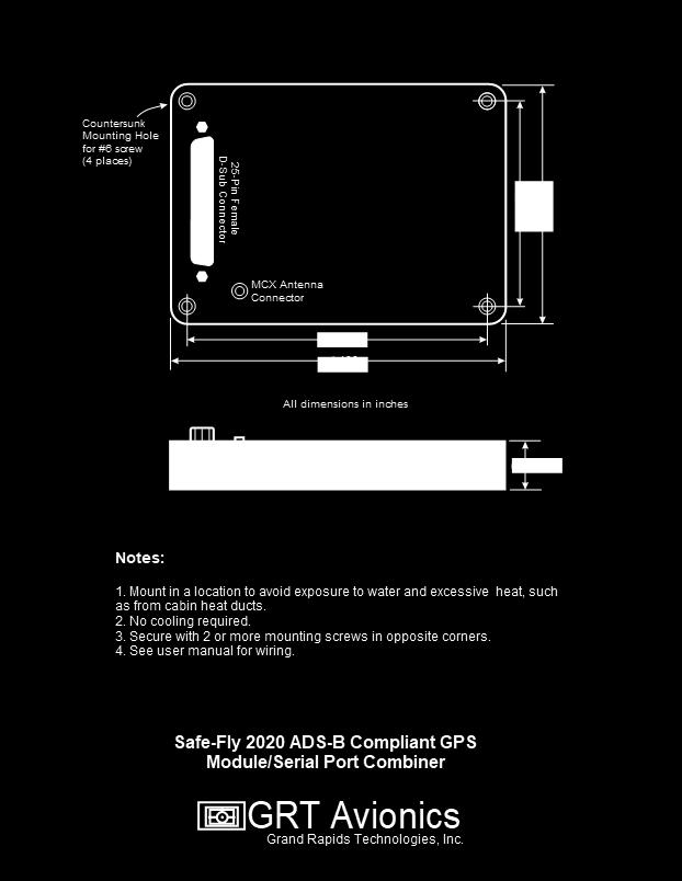
24 Dimensions 24

25 Typical Wiring 25
26 Included Cable Assembly The cable assembly is provided with a 25-pin male d-sub connector, housing, backshell, and a variety of wires pre-pinned with male contacts ready for insertion into the d-sub housing. In addition, 10 d-sub male contacts are provided. All wires for the adapter are 4 long, but can be replaced with longer wires as needed. When inserting the wires into the housing, be sure to insert them into the correct holes, as removing them requires a pin extraction tool, and can be difficult. Wire Color Suggested Function Red Power 1 Black Ground White Any Blue Any Orange Any Yellow Any Green Any Violet Any White/Green Serial Control In White/Blue Serial Control Out 26
Safe-Fly 2020 ADS-B Compliant GPS Module with Serial data Combiner/Expander
 Safe-Fly 2020 ADS-B Compliant GPS Module with Serial data Combiner/Expander Revision E 6/9/2017 GRTAvionics.com 1 Table of Contents Revision History...3 Description...4 Compatibility...4 Use with Non-Compatible
Revision A 03/31/2017 GRTAvionics.com. Serial Combiner/Expander
 Quad Serial data Combiner/Expander Revision A 03/31/2017 GRTAvionics.com 1 Table of Contents Revision History...3 Description...4 Compatibility...4 Use with Non-Compatible GRT and other systems...4 Serial
 ! o o o o o o o o o (Per the February 9, 2015 rule change to 14 CFR 91.225 (b)(1)(ii)) (A letter of authorization from the aircraft manufacturer is needed for installation in LSA aircraft) ± ! ADF
GRT External GPS Modules Equipment Supplement
 GRT External GPS Modules Equipment Supplement 30-May-2013 Table of Contents Section 1: Introduction 1.1 About GRT GPS modules...... 3 1.2 Data Port and Hardware Requirements 3 Section 2: Installation &
Dual Electronics XGPS170 ADS-B Receiver Equipment Supplement
 Dual Electronics XGPS170 ADS-B Receiver Equipment Supplement 3 9-Jul-2014 Revision Notes Revision Date Change Description A 17-Jun-2013 Initial Release A1 19-Jun-2013 Corrected error in Section 4 regarding
EFIS Horizon Cable Description
 EFIS Horizon Cable Description Dual Display Unit EFIS System Dual AHRS/Air Data Computer March 1, 2004 Rev A Grand Rapids Technologies, Inc. Revision History Rev A - 3/1/04 Initial Release Overview This
EFIS Horizon Cable Description
 EFIS Horizon Cable Description Single Display Unit Jan 23, 2004 Rev C Grand Rapids Technologies, Inc. Revision History 12/15/03 Initial Release Rev B - General Updates Rev C - 1/23/04 - Changed Red/White
uavionix and Ping are registered trademarks of uavionix Corporation and may not be used without express permission of uavionix.
 2018 uavionix Corporation. All rights reserved. Except as expressly provided herein, no part of this guide may be reproduced, transmitted, disseminated, downloaded or stored in any storage medium, for
The BOM [Broadcasting Outer Module]
![The BOM [Broadcasting Outer Module]](/thumbs/91/106681333.jpg "The BOM [Broadcasting Outer Module]") Avionics Reimagined The BOM [Broadcasting Outer Module] The first and only ALL-IN-ONE AVIONICS SUITE Distributed by: Adams Aviation Supply Co Ltd mail@adamsaviation.com www.adamsaviation.com BOM (Broadcasting
Avionics Reimagined The BOM [Broadcasting Outer Module] The first and only ALL-IN-ONE AVIONICS SUITE Distributed by: Adams Aviation Supply Co Ltd mail@adamsaviation.com www.adamsaviation.com BOM (Broadcasting
Installation Manual. Caution: Preliminary. Due to software development occurring at this time, this manual may contain inaccuracies and omissions.
 Installation Manual Caution: Preliminary Due to software development occurring at this time, this manual may contain inaccuracies and omissions. Manual Version: Preliminary Date: 10/18/04 Grand Rapids
ilevil 3 AW Wireless Integrated Avionics Module AD-AHRS, GPS, ADS-B 978 / 1090 MHz Receiver, Data recorder Instruction Manual
 ilevil 3 AW Wireless Integrated Avionics Module AD-AHRS, GPS, ADS-B 978 / 1090 MHz Receiver, Data recorder Instruction Manual ilevil 3 AW SD CARD PORT GPS ANTENNA ADS-B ANTENNA MINI USB PORT CHARGING LED
EQUIPMENT INSTALLATION MANUAL. for the GDC59 CONVERTER P/N
 EQUIPMENT INSTALLATION MANUAL for the P/N 1095-4000-01 DAC International 6702 McNeil Drive Austin, TX 78729 Copyright 2009, DAC International. All rights reserved. Rev IR Page 1 of 17 RECORD OF REVISIONS
skybeacon TM STC Installation Manual
 skybeacon TM STC Installation Manual UAV-1002305-001 2019 uavionix Corporation. All rights reserved. Except as expressly provided herein, no part of this guide may be reproduced, transmitted, disseminated,
EFIS Horizon Display Unit Connector Definitions
 EFIS Horizon Display Unit Connector Definitions June 7,2004 Rev D Grand Rapids Technologies, Inc. Revision History Rev C - Changed naming convention to +Left/+Right and +Up/+Down for loc/gs inputs. No
VSI200E Vertical Speed Indicator with Altitude Encoder
 VSI200E Vertical Speed Indicator with Altitude Encoder THIS IS A TRANSPORT CANADA APPROVED MANUAL The following checklist outlines the required articles for the VSI200E Vertical Speed Indicator. Documentation
Horizon HX Wiring Supplement
 Horizon HX Wiring Supplement Revision A3-8/2/2016 For units shipped after January 8, 2013 Applies to single or multi-display systems with single or dual AHRS and the following Wiring Harness Part Numbers:
Vector Compact-S (NMEA 0183) Vector Compact-N (NMEA 2000) Quick Installation Guide
 Vector Compact-N (NMEA 2000) Quick Installation Guide") Vector Compact-S (NMEA 0183) Vector Compact-N (NMEA 2000) Quick Installation Guide Seapilot VECTOR COMPACT-S NMEA 0183 (Serial) Kit Housing Screw Caps and O-ring Housing M6 Screws Mounting Base Front View
Vector Compact-S (NMEA 0183) Vector Compact-N (NMEA 2000) Quick Installation Guide Seapilot VECTOR COMPACT-S NMEA 0183 (Serial) Kit Housing Screw Caps and O-ring Housing M6 Screws Mounting Base Front View
Models HX, HS & WS. Installation Manual
 GRT HORIZON Models HX, HS & WS Installation Manual Rev. A February 2009 Grand Rapids Technologies, Inc. 3133 Madison Avenue SE Wyoming MI 49548 616-245-7700 www.grtavionics.com INTENTIONALLY BLANK GRT
EQUIPMENT INSTALLATION MANUAL. for the ARINC ALTITUDE ALERTER INTERFACE P/N
 EQUIPMENT INSTALLATION MANUAL for the ARINC ALTITUDE ALERTER INTERFACE P/N 1085-4000-01 DAC International 6702 McNeil Drive Austin, TX 78729 Copyright 2008, DAC International. All rights reserved. IR.doc
Sport SX/Sport EX/Horizon EX. Installation Manual
 Sport SX/Sport EX/Horizon EX Installation Manual Revision G 20-April-2017 Copyright 2016 3133 Madison Ave. SE Wyoming, MI 49548 (616) 245-7700 www.grtavionics.com ii Revision F SPORT Installation Manual
EQUIPMENT INSTALLATION MANUAL. for the GDC66 FUEL QUANTITY ADAPTER UNIT P/N Rev B
 EQUIPMENT INSTALLATION MANUAL for the GDC66 FUEL QUANTITY ADAPTER UNIT P/N 1107-4000-01 Rev B DAC International 6702 McNeil Drive Austin, TX 78729 Copyright 2013, DAC International. All rights reserved.
10.4 HXr EFIS. GRT Avionics. (616) fax (616) above, beyond.
 fax (616) above, beyond.") Grand Rapids Technologies, Inc. 10.4 HXr EFIS The large screen EFIS for your experimental airplane. Insets...Preserving the View One look at the HXr and you sense the situational awareness provided by
Grand Rapids Technologies, Inc. 10.4 HXr EFIS The large screen EFIS for your experimental airplane. Insets...Preserving the View One look at the HXr and you sense the situational awareness provided by
2nd Generation. Pilot s Guide. ForeFlight
 2nd Generation Pilot s Guide ForeFlight Copyright Information Stratus Second Generation Pilot s Guide, 2012-2013 Appareo Systems, LLC. All Rights Reserved. All content within is copyrighted by Appareo
P/N ( )
") EQUIPMENT INSTALLATION MANUAL For the GDC55 ARINC 49 DATA CONVERTER P/N 1089-4000-01-001( ) DAC International 670 McNeil Drive Austin, TX 7879 Copyright 008, DAC International. All rights reserved. Page
EQUIPMENT INSTALLATION MANUAL For the GDC55 ARINC 49 DATA CONVERTER P/N 1089-4000-01-001( ) DAC International 670 McNeil Drive Austin, TX 7879 Copyright 008, DAC International. All rights reserved. Page
Installation Manual AIS 240B-35
 Installation Manual AIS 240B-35 SANDIA aerospace 3700 Osuna Rd NE, Ste 711 Albuquerque, NM 87109 www.sandia.aero 306464 This document and the information contained herein is the proprietary data of SANDIA
Aeronautical Navigator
 Aeronautical Navigator COCKPIT DOCKING STATION INSTALLATION GUIDE Standard and OEM Versions Your Journey, Our Technology DISCLAIMER & WARNINGS This product is not TSO-certified and have received no EASA
AFMS, Garmin G5 AML STC Rev. 1 FAA APPROVED Page 2 of 7
 LOG OF REVISIONS Date of Rev Page Description FAA Approval Approval 1 All Original Issue See Cover See Cover FAA APPROVED Page 2 of 7 TABLE OF CONTENTS SECTION 1. GENERAL... 4 SECTION 2. LIMITATIONS...
Installation Manual AIS 200B-35
 Installation Manual AIS 200B-35 SANDIA aerospace 3700 Osuna Rd NE, Ste 711 Albuquerque, NM 87109 www.sandia.aero 306463 This document and the information contained herein is the proprietary data of SANDIA
EQUIPMENT INSTALLATION MANUAL. for the GFD11 COCKPIT CONTROL UNIT
 EQUIPMENT INSTALLATION MANUAL for the GFD11 COCKPIT CONTROL UNIT DAC International 6702 McNeil Drive Austin, TX 78729 June 10, 2002 Copyright 2002, DAC International. All rights reserved. Rev D Page 1
LYNX MULTILINK SURVEILLANCE SYSTEM
 Lynx Brochure 2-18-15_MB-2005-10.qxd 2/20/2015 11:16 AM Page 1 LYNX MULTILINK SURVEILLANCE SYSTEM Aviation Products Lynx Brochure 2-18-15_MB-2005-10.qxd 2/20/2015 11:16 AM Page 2 LYNX NGT-9000 The Lynx
ADL150 User and Installation Manual. Version
 ADL150 User and Installation Manual Version 1.00 15.02.2017 ADL150 User and Installation Manual 1 / 12 Revision 1.00-15.02.2017 1 Version History Version 1.00 published 15.02.2017 2 Page Index This manual
Installation Manual AIS AIS 200A-35
 Installation Manual AIS 200-35 AIS 200A-35 SANDIA aerospace 3700 Osuna Rd NE, Ste 711 Albuquerque, NM 87109 www.sandia.aero This document and the information contained herein is the proprietary data of
AFMS, Garmin G5 AML STC Rev. 3 Page 2 of 10
 LOG OF REVISIONS Rev Page Description Date of Approval FAA Approval 1 All Original Issue 7/22/2016 Robert Murray ODA STC Unit Administrator 2 All Added information regarding G5 DG/HSI 4/28/2017 Robert
ZLog Z7 High Altitude Data Logging System
 ZLog Z7 High Altitude Data Logging System 2013-02-04 Page 1 of 16 Introduction ZLog was designed to provide a lightweight, compact device for measuring and recording data in high-altitude scientific experiments.
ADL150 / ADL150B User and Installation Manual. Version
 ADL150 / ADL150B User and Installation Manual Version 2.00 21.08.2018 ADL150 User and Installation Manual 1 / 14 Revision 2.00-21.08.2018 1 Version History Version 1.00 published 15.02.2017 Version 1.01
AT01 AIRPLANE FLIGHT MANUAL
 1.0 General The airplane is equipped with a Bendix / King KMD 150 Multifunction Display / GPS Navigator herein referred as the Navigator. The KMD 150 is capable of providing VFR (IFR) enroute and terminal
DMK 11A & 11A GPS Owners Manual
 DMK 11A & 11A GPS Owners Manual Table of Contents Section I Description of DMK 11A & 11A-GPS 1.1 Introduction 1.2 Background 1.3 Infrastructure Connection 1.4 Components 1.5 Input Protocols 1.6 Configuration
Installation Manual and Operating Instructions. Model MD32 Series Remote Magnetometer
 Installation Manual and Operating Instructions Model MD32 Series Remote Magnetometer Mid-Continent Instrument Co., Inc. dba Mid-Continent Instruments and Avionics 9400 E. 34 th Street N. Wichita, KS 67226
Approved GPS and Software List For Vizion PMA Autopilot And Procedure for Approving Additional GPS or Software
 Approved GPS and Software List For Vizion PMA Autopilot And Procedure for Approving Additional GPS or Software RESTRICTION ON USE, DUPLICATION, DISCLOSURE OF PROPRIETARY INFMATION THIS DOCUMENT CONTAINS
VP- X Pro & VP- X Sport
 VP- X Configurator Release Notes As of version 1.6 (May 13, 2013) This document updated October 31, 2013 Contents 1. Models...1 2. Updating the VP-X Pro and Sport firmware (Automatic)...1 3. Software Upgrade
Bluetooth GPS Receiver. User s Guide
 HOLUX Bluetooth GPS Receiver User s Guide HOLUX Technology Inc. 1F, No. 30, R&D Rd. II, HsinChu City 300, Science-based Industrial Park, Taiwan TEL: 03-6687000 FAX: 03-6687111 E-Mail: info@holux.com.tw
Avtec, Inc. Lighting Systems
 6 Industrial Park Cahokia, IL 62206 Phone (618) 337-7800 Fax (618) 337-7976 E-Mail tech_info@avteclighting.com Report No. INSTALLATION OPERATION MAINTENANCE MANUAL, LED STRIP LIGHT, P/N 01-11-0010 P/N
BCON 1. User Guide. Document Number: SSD1000A4 Rev 1.4,
 BCON 1 User Guide Rev 1.4, 2017-07-31 SKYSENSE AB Kistagången 12, SE-164 40 Kista, Sweden, support@skysense.io Page 1 of 19 Contents User Guide...1 Contents...2 Introduction...3 Overview of the BCON1 Transmitter...3
MODEL A-30 ALTITUDE DIGITIZER OPERATION MANUAL INSTALLATION MANUAL
 LIMITED WARRANTY THIS MODEL A-30 DIGITIZER IS WARRANTED BY ACK TECHNOLOGIES INC. AGAINST DEFECTS IN MATERIALS AND WORKMANSHIP FOR A PERIOD OF THREE YEARS FROM IT S MANUFACTURING DATE. THIS WARRANTY IS
Saab TransponderTech. INSTALLATION GUIDE J4N Junction Box for R4 Navigation System
 Saab TransponderTech INSTALLATION GUIDE J4N Junction Box for R4 Navigation System Page i i Copyright The entire contents of this manual and its appendices, including any future updates and modifications,
For more details and updates go to our website, boatcommand.com.
 Installation Manual Compatibility Compatibility is easy. Our device needs a boat with a working battery. Once installed on your boat, you can monitor and control your boat from anywhere you have internet
Altair RU. Owner s Manual. Document name: AtrRU-EN Document version: 0.3 Release date: 25/03/2009
 Altair RU Owner s Manual Document name: AtrRU-EN Document version: 0.3 Release date: 25/03/2009 triadis engineering GmbH Eichholzstrasse 7 Postfach CH-3254 Messen Phone: +41 (0)31 768 15 15 Fax: +41 (0)31
Avtec, Inc. Lighting Systems
 6 Industrial Park Cahokia, IL 62206 Phone (618) 337-7800 Fax (618) 337-7976 E-Mail tech_info@avteclighting.com Report No. INSTALLATION OPERATION MAINTENANCE MANUAL, LED STRIP LIGHT, P/N 01-11-0007 P/N
GeoAudio+ Portable GPS to Audio Encoder / Decoder with Internal High Precision GPS Receiver and Antenna. Version 1.00
 GeoAudio+ Portable GPS to Audio Encoder / Decoder with Internal High Precision GPS Receiver and Antenna Version 1.00 Copyright 2012 Intuitive Circuits, LLC D escription GeoAudio+ with built-in GPS receiver
PCEFIS VERSION 3.6 SOFTWARE SUMMARY DESCRIPTION Sellers Aviation Inc
 PCEFIS VERSION 3.6 SOFTWARE SUMMARY DESCRIPTION WWW.PCFLIGHTSYSTEMS.COM Sellers Aviation Inc. 352-804-7217 PCFLIGHTSYSTEMS PCEFIS VERSION 3.6 SOFTWARE DISPLAY SUMMARY Bearing to destination* Heading (slaved
Installation Instructions for: Channel Thermocouple Amplifier
 Installation Instructions for: 30-2204 4 Channel Thermocouple Amplifier The Advanced Engine Management (AEM) 4 channel thermocouple amplifier revolutionizes temperature measurements by providing laboratory
This document set is applicable to the following part number configurations:
 This document set is applicable to the following part number configurations: Part Number Kit Configuration Instrument Sensors VA200 VA200 - VA200K VA200 1 X A200-HAS Voltmeter and ammeter systems VA200X
GRT Vision Addendum to the GRT Remote App User Manual 08/19/2015
 GRT Vision Addendum to the GRT Remote App User Manual 08/19/2015 Also refer to the GRT Remote App User Manual available at: http://www.grtavionics.com/grt%20remote%20app.pdf GRT AVIONICS, INC. 1 GRT VISION
XGPS170D OWNER'S MANUAL GPS
 OWNER'S MANUAL GPS + Dual-Band ADS-B Weather and Traffic Receiver FCC ID: GJW-XGPS170 IC ID: 4038A-XGPS170 Introduction Thank you for purchasing the XGPS170D ADS-B Receiver from Dual Electronics. The XGPS170D
Vutog GPS Simulator White Paper
 Vutog GPS Simulator White Paper -------------------------------------------------------- The Vutog GPS Simulator provides a complete suite for all your GPS simulating needs and more. It is designed to
SOFTWARE SERVICE BULLETIN NO.: 0740 Rev A
 SOFTWARE SERVICE BULLETIN NO.: 0740 Rev A TO: All Garmin Aviation Service Centers DATE: SUBJECT: 400W / 500W Series Unit s software upgrade to Main Software version 3.00 & GPS Software version 3.0 PURPOSE
Quick Start Installation Guide
 apc/l Quick Start Installation Guide Version A2 Document Part Number UM-201 May 2010 OVERVIEW The apc/l is an intelligent access control and alarm monitoring control panel which serves as a basic building
5B Series 16 Channel Backplane 5B01 FEATURES APPLICATIONS PRODUCT OVERVIEW FUNCTIONAL BLOCK DIAGRAM
 5B Series 16 Channel Backplane 5B01 FEATURES Mix and Match 5B Series I/O Module Capability Factory Mutual (FM) Approved Approved for Use in Class I, Division2, Groups A, B, C, and D Locations. CE Certified:
PingStation User and Installation Guide
 PingStation User and Installation Guide REVISION D UAV-1001358-001 Page 1 25 UAV-1001358-001 Page 2 25 2017 uavionix Corporation. All rights reserved. uavionix Corporation 380 Portage Ave. Palo Alto, CA
D-0005 BOM (Broadcasting Outer Module) Pilot s Guide LEVIL AVIATION 1704 KENNEDY POINT, SUITE 1124 OVIEDO, FL 32765
 Pilot s Guide LEVIL AVIATION 1704 KENNEDY POINT, SUITE 1124 OVIEDO, FL 32765") 2017 D-0005 BOM (Broadcasting Outer Module) Pilot s Guide LEVIL AVIATION 1704 KENNEDY POINT, SUITE 1124 OVIEDO, FL 32765 Effective Date 11/7/17 Page 1 of 12 This manual is the property of Levil Aviation.
2017 D-0005 BOM (Broadcasting Outer Module) Pilot s Guide LEVIL AVIATION 1704 KENNEDY POINT, SUITE 1124 OVIEDO, FL 32765 Effective Date 11/7/17 Page 1 of 12 This manual is the property of Levil Aviation.
Installation & Quick Start Guide iais Wireless AIS Receiver
 Installation & Quick Start Guide iais Wireless AIS Receiver and NMEA Server QUICK START iais VR1.01 1. Introduction Congratulations on the purchase of your iais Receiver. It is recommended that your receiver
Flytec Bluetooth Option
 Option English Setup Bluetooth In order to use the Bluetooth/SMS option, the Bluetooth module must be installed and tested by Flytec or Bräuniger. With the BT module installed and the SMS feature unlocked
VANTAGE CL1. Installation and use of the CL1 Karting Data Kit
 Installation and use of the CL1 Karting Data Kit Table of Contents What s in the box 3 Items needed for installation 4 CL1 registration 5 D3 app install 6 Battery installation 7 Mounting the CL1 data box
StarFinder Aire User Manual
 Document No.: Document Type: Security Level: 270-UM-001 User Manual Open StarFinder Aire User Manual (Preliminary) Version 1.00 Dec. 05, 2015 Copyright Laipac Technology Inc. Release History Revision Date
This document set is applicable to the following part number configurations:
 This document set is applicable to the following part number configurations: Part Number Kit Configuration Instrument Sensors VA200 VA200 - VA200K VA200 1 X A200-HAS Voltmeter and ammeter systems VA200X
Table of Contents 1 ABOUT THIS GUIDE CONTACT INFORMATION ANTENNA INSTALLATION... 4
 Table of Contents 1 ABOUT THIS GUIDE... 3 1.1 CONTACT INFORMATION... 3 2 ANTENNA INSTALLATION... 4 2.1 GENERAL INFORMATION... 4 2.2 SPECIFIC MOUNTING EXAMPLES... 5 2.3 CONNECTOR MOISTURE PROTECTION...
955 ebrik INSTALLATION MANUAL. Series ebrik ABSOLUTE PROCESS CONTROL KNOW WHERE YOU ARE... REGARDLESS LINEAR DISPLACEMENT TRANSDUCERS
 Series ebrik INSTALLATION MANUAL LINEAR DISPLACEMENT TRANSDUCERS ABSOLUTE PROCESS CONTROL KNOW WHERE YOU ARE... REGARDLESS Introduction The is an accurate programmable, auto-tuning, noncontact, linear
Microair Avionics Pty Ltd Airport Drive Bundaberg Queensland 4670 Australia Tel: Fax:
 Microair Avionics Pty Ltd Airport Drive Bundaberg Queensland 4670 Australia Tel: +61 7 41 553048 Fax: +61 7 41 553049 e-mail: support@microair.com.au About This Document This manual describes the various
DESIGN SPECIFICATION # R1 Model AHRS-500 P/N ARINC 407 TO ARINC 429 ADAPTOR CTRL # /17/96
 DESIGN SPECIFICATION # 550-2000-R1 Model AHRS-500 P/N 550-2000 ARINC 407 TO ARINC 429 ADAPTOR CTRL # 96060006 10/17/96 Skylight Avionics 38629 6th Street East Palmdale, California (661) 265-0497 INDEX
12.3 Pro Dash Quick Start Guide
 12.3 Pro Dash Quick Start Guide 553-111 CONTENTS: Package Contents... 3 Mounting... 3 Connections... 4 Main Connector... 4 CAN Extension Harness... 6 USB... 7 GPS Antenna... 7 Cleaning... 7 Touchscreen
This document set is applicable to the following part number configurations:
 This document set is applicable to the following part number configurations: Part Number Kit Configuration Instrument Sensor TM202 TM202 - TM202B TM202 1 X A200-HMB TM202S TM202 1 X A200-HMS TM202R TM202
ETM RECORDER P/N:
 ETM RECORDER P/N: 943200-10 MANUAL P/N: M943200-10 REV 6831 Oxford Street St. Louis Park, MN 55426-4412 Sales: (800) 328-0584 Customer Service: (800) 388-2849 Customer Service: (952) 836-2269 www.shadin.com
Short guide. Trackunit 401 SmartID. Version 1.4, June 2014
 Short guide Trackunit 401 SmartID Version 1.4, June 2014 Mounting instructions Placement of the unit on the machine Do NOT mount the unit horizontally. Make sure that water can run off the unit. Do NOT
Garmin G3X Touch README File
 Garmin G3X Touch README File G3X-PRE-SETS-READ-ME-11-29-18 Rev 10 Overall it is our hope that use of the settings files will make installing new products and maintaining current software on older EFIS
EQUIPMENT INSTALLATION MANUAL, GDC64, TABLET AIRCRAFT INTERFACE UNIT Rev C
 EQUIPMENT INSTALLATION MANUAL, GDC64, TABLET AIRCRAFT INTERFACE UNIT 1104-2510-01 Rev C 2015, DAC International All Rights Reserved 6702 McNeil Dr. Austin, Texas 78729 (512) 331-5323 Phone (512) 331-4516
GPS MOBILE LOCATOR USER S MANUAL
 GM-48S < RS-232 > GPS MOBILE LOCATOR USER S MANUAL Contents INTRODUCTION & APPLICATIONS.........3 PACKAGE CONTENTS.4 GETTING STARTED.. 5 OPERATING PROCEDURE.. 6 SPECIFICATION.....7 APPENDIX... 8 WARRANTY..9
Electronic Conspicuity and the GAINS Project. Julian Scarfe Bob Darby AGM 2018
 Electronic Conspicuity and the GAINS Project Julian Scarfe Bob Darby AGM 2018 What is electronic conspicuity? ª Conventional: ground radar detects other aircraft pilots interpret traffic information from
6222 Two Door Module Technical Operations Manual
 6222 Two Door Module Technical Operations Manual TABLE OF CONTENTS Specifications...3 Overview...4 Operations...5 Custom Access Mode...5 Standard Access Mode...5 Offline Access Mode...5 Offline Memory...5
4K/UHD Five-Input Universal Switcher with Wireless Presentation Link
 4K/UHD Five-Input Universal Switcher with Wireless Presentation Link Installation Guide The Atlona is a 5 1 multi-format switcher with wireless presentation capability. It provides universal (bring your
Local Set Point Module Operating Bulletin
 Local Set Point Module Operating Bulletin 1 Notice: The manufacturer reserves the right to make any changes and improvements to the products described in this manual at any time and without notice. This
4.8 Expansion Module MAC00-FS1/FS4
 .8 Expansion Module MAC00-FS/FS MAC00-FS With M connectors MAC00-FS With D sub connectors TT08GB.8. High speed serial RS8 module MAC00-FS and FS Introduction The MAC00-FS and FS are used for high speed
Frequently Asked Questions
 Model 881 SPORTSCAN Digital Sidescan Sonar Frequently Asked Questions What can I use to power the SportScan? The SportScan requires a DC voltage between 10 and 16 volts for proper operation (+12VDC @ 0.5A
FlightBox User Guide
 FlightBox User Guide Copyright 2017, Open Flight Solutions All Rights Reserved Published under the Creative Commons Attribution Non-Commercial License Table Of Contents Table Of Contents Regulatory Notices
This document set is applicable to the following part number configurations:
 This document set is applicable to the following part number configurations: Part Number Kit Configuration Instrument Sensor FL202G FL202G Use with CIES Inc. TSO d fuel senders on Cirrus Aircraft SR20,
Operation Manual. Fieldbus system EX510-GDN1. DeviceNet Compatible GW unit
 Fieldbus system DeviceNet Compatible GW unit Operation Manual EX50-GDN URL http://www.smcworld.com Akihabara UDX 5F, --, Sotokanda, Chiyoda-ku, Tokyo 0-00, JAPAN Phone: +8-507-89 Fax: +8-598-56 Note: Specifications
SDR MAINTENANCE INTERFACE PANEL
 SDR MAINTENANCE INTERFACE PANEL USER'S MANUAL (version 3.0) www.db-integrations.com Table Of Contents: Maintenance Panel Overview:...4 User's Manual Applicability:...4 Equipment Part Numbers:...4 Physical
GV-EL124S Electric Strike
 GV-EL124S Electric Strike Featured with a built-in door status sensor, the GV-EL124S is a fail-secure electric strike, but it is field convertible from fail secure to fail safe. It can be mounted either
HOLUX M-1200 Bluetooth GPS Receiver User s Manual M Bluetooth GPS Receiver. User s Guide
 HOLUX M-1200 Bluetooth GPS Receiver User s Manual M-1200 Bluetooth GPS Receiver User s Guide 07,2007 Rev.A HOLUX Technology Inc. 1F, No. 30, R&D Rd. II, HsinChu City 300, Science-based Industrial Park,
GPS Module. Ct-G431. Specifications Sheet V0.3
 GPS Module Ct-G431 Specifications Sheet V0.3 Features: SiRF StarIV ultra low power chipset Compact module size for easy integration : 15 x 14 x 2.8 mm UART/ I 2 C pins reserved for customizing special
DESIGN SPECIFICATION Model LRN-500, P/N DIGITAL TO ANALOG ADAPTOR
 Model LRN-500, P/N 500-5602 DIGITAL TO ANALOG ADAPTOR Skylight Avionics 38629 6th Street East Palmdale, California INDEX Section Title Page 1. Operating Instructions 1 2. Equipment Limitations 1 3. Installation
GPS Module. Ct-G432. Specifications Sheet V0.1
 GPS Module Ct-G432 Specifications Sheet V0.1 Features: SiRF StarIV internal ROM-based ultra low power chipset Compact module size for easy integration : 10.6 x 10 x 2.3 mm Ct-G432 module provide an I 2
ZLog Z7 High Altitude Data Logging System
 ZLog Z7 High Altitude Data Logging System 2015-03-02 Page 1 of 18 Introduction ZLog was designed to provide a lightweight, compact device for measuring and recording data in high-altitude scientific experiments.
ThunderBolt Display. by Adam Maurer, VK4GHZ
 ThunderBolt Display by Adam Maurer, VK4GHZ Overview ThunderBolt Display is a compact plug n play stand-alone display specifically for Trimble s ThunderBolt Disciplined Clock, providing a comprehensive
JET RANGER / LONG RANGER INSTALLATION MANUAL. Tyler - Nose Mount For Bell 206 & 206L Series Helicopters FAA STC # SH2256NM
 JET RANGER / LONG RANGER INSTALLATION MANUAL Tyler - Nose Mount For Bell 206 & 206L Series Helicopters FAA STC # SH2256NM PLEASE RETURN THIS MANUAL WITH EQUIPMENT This manual is available for download
INSTALLATION SPECIFICATION DIGITAL TO FINE/COURSE XYZ SYNCHRO MODEL, ADC-600, P/N
 INSTALLATION SPECIFICATION DIGITAL TO FINE/COURSE XYZ SYNCHRO SKYLIGHT AVIONICS 38629 6th St. East Palmdale, Ca. 93550 (661) 265-0497 TABLE OF CONTENTS REFERENCE SECTION PAGE (i) OPERATING INSTRUCTIONS
FA-2448 SIX POSITION Filter Wheel
 15 Discovery Way, Acton, MA 01720 Phone: (978)263-3584, Fax: (978)263-5086 Web Site: www.acton-research.com Operating Instructions Acton Research Corporation FA-2448 SIX POSITION Filter Wheel Rev. 3.05.17
BlueMAX Bluetooth Adapter Installation Instructions
 [BLUEMAX INSTALLATION INSTRUCTIONS] i BlueMAX Bluetooth Adapter Installation Instructions Document no. 2456-05 Date: 2017-06-07 Revision 5 Approved: Control-J Pty. Ltd. 100 Hursley Rd. Redbank NSW 2446
In-Sight 7010C/7200C/7400C
 The following sections list general specifications for the In-Sight vision system. Vision System Specifications Table 3-1: Vision System Specifications Specifications Minimum Firmware Requirement Job/Program
This document set is applicable to the following part number configurations:
 This document set is applicable to the following part number configurations: Part Number FL201D Description Fuel level instrument for digital senders, one tank Part Number FL202D Description Fuel level
Microair Avionics Pty Ltd Airport Drive Bundaberg Queensland 4670 Australia Tel: Fax:
 Microair Avionics Pty Ltd Airport Drive Bundaberg Queensland 4670 Australia Tel: +61 7 41 553048 Fax: +61 7 41 553049 e-mail: support@microair.com.au About This Document This manual describes the various