Making it easy to obtain digital forensic data from heavy vehicle crashes.
|
|
|
- Conrad Anthony
- 6 years ago
- Views:
Transcription


1 1 Making it easy to obtain digital forensic data from heavy vehicle crashes.

2 2 Using and Understanding the Smart Sensor Simulator 2


3 3 Understanding the Need for the SSS2: Connecting to Electronic Control Units A working vehicle with power, ECUs and communications may not be available. Simulating sensors and actuators for an ECU is important to reduce new Fault Codes. Criminal and civil litigation would like to see reduced fault or fault-free data from ECUs. A crash test conducted by Dr. Jeremy Daily at The University of Tulsa
 Stationary trucks don t give rich data sets.")

4 4 Smart Sensor Simulator 2 Problem Solution Fit Current Problems Developing and testing with actual trucks is expensive Rental/Leasing Storage and maintenance Limited access (one at a time) Stationary trucks don t give rich data sets. Cutting edge research risks bricking a truck Expensive wiring harnesses Need Fault-Free Environment Smart Sensor Simulator Solutions No rental or storage fees. Simple USB-to-Serial command interface with a GUI Can rapidly adjust settings to clear or set various fault codes Use one truck ECU at a time Multiple SSS2 are easy to deploy Can piggy-back ECUs for complete truck build out The SSS2 fits in your pants pocket Common Molex connector interface for easy wiring


5 5 The SSS2 as a Tool in the Toolbox Interfacing with Heavy Vehicle Electronic Control Units requires cables and connections. The SSS2 Provides: Power Ignition Key Switch Communications CAN/J1939 J1708 LIN Analog Sensor Simulation Actuators Emulation Part of an Investigative System Computer with Diagnostics Software RP1210 Device or Forensic Link Adapter Detroit Diesel DDEC 13 Common Powertrain Controller connected to the SSS2
6 6 Truck Simulation using the Smart Sensor Simulator 2 SSS2 Interface Application Heavy Vehicle ECU (Freightliner CPC4 shown) Custom Interface Cable Device Under Test (FLA shown) SSS2


7 7 Smart Sensor Simulator 2 Origins DARPA/ Univ. of Tulsa Truck In a Box 2012 Synercon Tech. Smart Sensor Simulator 2014 Synercon Tech. Smart Sensor Simulator Goal: Provide researchers and investigators easy access to Electronic Control Modules outside the heavy vehicle.
8 8 The Value Proposition for the Smart Sensor Simulator 2 Truck-in-a-box technology to simulate sensors and actuators on a heavy truck Enables fault-free downloading conditions for forensic examination. Establishes power and communication for electronic control units (ECUs) from heavy vehicles Composable networking connections to build out multiple module systems. Software controllable interface to adapt to multiple ECUs Open source hardware and software


9 9 How the SSS2 Works An ECU reads electrical signals from sensor systems. Two wire sensors Three wire sensors Actuators or Solenoids to +12V Actuators or Solenoids to Ground Pulse or Square Wave signals Controller Area Network (CAN) Switches The SSS2 can generate all these signal or connection types. Schematic Layout from a DDEC VI


10 10 Smart Sensor Simulator 2 Pinouts Some pins are multiplexed they can do more than one thing.


11 11 Two Wire Sensors: Resistance Based Temperature Sensors SSS2 provides resistors to ground through digital potentiometers. Inside the SSS2 Inside the ECU Images from Wikipedia. The original uploader was Psanderson at English Wikipedia - Transferred from en.wikipedia to Commons by JohnnyMrNinja using CommonsHelper., GFDL 1.2,

.")
12 12 Resistor To Ground Settings driven through the SSS2 Interface Application Terminal A is disconnected. Minimum Wiper to Ground resistance is about 260 ohms. Can be used to let the ECU detect current flow for some actuators. Simulate switches to ground (like Idle Validation) Typically use 100k potentiometers for temperature. Use 10k potentiometers for actuators and digital signals (pull-down resistors). The SSS2 uses the Microchip MCP41HV51 Digital Potentiometer.


13 13 Simulating a Three Wire Sensor Voltage dividers produce a voltage signal based the wiper position. Common for pressure sensors. Half Bridge sensors are voltage dividers. APP snip taken from the Navistar MaxxForce schematic.


14 14 Pulse Width Modulated Signals Emulate Accelerator Pedal Positions Can generate speed and RPM (not for forensic use)


15 15 Analog Outputs Produce steady voltage from 0 to 5 VDC. Emulates pressure sensors If set to 0V, the ECU sees a small resistor to ground. Snip from the Cummins CM870 Fault Information System

16 16 High Current Adjustable Regulator 5.0 Amp Adjustable Linear Regulator 1.9V to 11VDC Pins J18:11 and J24:19 Low Power Testing Example: Bendix Brake Controllers Power on with 8.0 VDC Low Power Fault Code present No existing faults are overwritten


17 17 Adjusting the SSS2 Settings Hard Way Type in serial commands Easy Way Smart Sensor Simulator Interface Application


18 18 Example of Adjusting the SSS2 Slide to adjust voltage


19 19 Example of Adjusting the SSS2 See the meter match the slider value. Can also directly type voltage and press the Set Voltage button. Probe connected to J24:19 and Ground Move the slider to a minimum value.

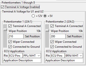
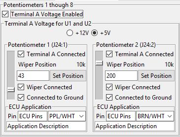
20 20 Adjust Digital Potentiometer as a Voltage Divider 210/255 43/255

21 21 Low Level Access to the SSS2 Based on the Teensy 3.6 USB development platform from PJRC.com Source Code and Schematics are available on Github: Complete listing of all the Serial commands Examples for CAN and sensor simulation Useful for building your own applications

22 22 SSS2 Interface Application Download from Controls the adjustable analog signal generation in the SSS2 Analog Voltage Output for Pressure Sensors Pulse Width Modulated Output - Tone ring generation and Accelerator Pedals Digital Potentiometers Temperature sensors, Accelerator Pedals Low Level CAN/J1939 message generation Simulate network traffic from other ECUs Create multi-packet bursts Send individual CAN frames CAN Frame Data Logger Sorts by ID Exports to CSV file

23 23 Step 1: Download the SSS2 Interface Application


24 24 Step 2: Install the Application Requires Admin Privileges Creates an SSS2 folder in Documents Contains SSS2 Settings Files
")
25 25 Step 3: Connect Power, USB, VDA and an Exemplar ECU Don t turn on the key switch yet. VDA = Vehicle Diagnostic Adapter (like the FLA or Nexiq)

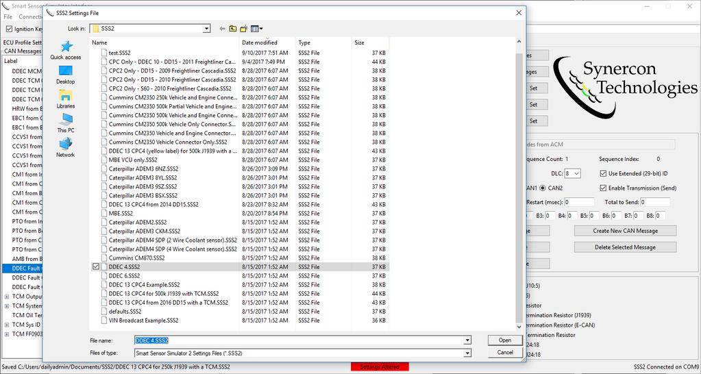
26 26 Step 4: Load the SSS2 Setting File
27 27 Step 5: Confirm Settings (Forensic Use) If performing a Forensic Investigation connect an Exemplar ECU with the same programming as the Subject ECU. Turn on the key switch and verify operation. Adjust settings if necessary Add CAN messages if needed Turn key switch off, wait until the messages turn off Unplug the exemplar module, but not the SSS2 (this keeps the settings loaded) Plug in the Subject ECU (Settings will hold from the previous session) Turn on the Key Switch and perform the download. Note: Failure to do this step may result in undesired Fault Codes being set on the Subject ECU

28 28 Step 6: Turn the Key Switch On
29 29 CAN Data Logger Check Connection
30 30 Step 7: Download Data
. Can store case file information. Open and view with a text editor. Synercon Technologies provides example.sss2 files.")
31 31 What is an SSS2 Settings File? A JSON text file to store settings data used for a particular session. Uses a SHA-256 check to ensure file has not been altered outside the SSS2 Interface App. Stores all the adjustable parameters (including CAN). Can store case file information. Open and view with a text editor. Synercon Technologies provides example.sss2 files. Users should generate their own files for each case.
.")
32 32 Saving Files The SSS2 Interface App can save settings files SSS2 should be connected. The correct Unique ID is needed. File keeps track of dates and times automatically. Status bar shows file location. Current settings are checked against the saved settings with a Secure Hash Algorithm (SHA). Green Box = settings match the file Red Box = Settings have changed
33 33 Opening Files Files open quickly, but load onto the SSS2 slowly. Press CTRL-O, Press the Open Settings File button or Select the File Menu and Open. Most Synercon Technologies provided files will have ECU data that was used for the test. Engine Serial Number Year, Make, Model Other notes Files are saved per ECU and are not general across all ECUs in that family. Exemplar Module testing is important to make sure the Synercon template file will work. ECUs with similar outward appearance can have different software or internal circuits.

34 34 CAN Message Logging Example of a CPC from a DDEC 10 with 500k CAN on the PT-CAN
35 35 CPC from DDEC 10 CAN Traffic The SSS2 logger only captures external traffic (not what it produces).

36 36 CAN Data Logger CAN data is streamed over USB in binary form. SSS2 Interface App decodes the binary and stores it in a list. Display tables are based on ID If a new CAN ID is found, it is entered into the display table Messages with existing CAN IDs add an increment to the ID counter ID rates are calculated. Saving the Buffer creates a CSV file and clears the list of messages. CSV file can be opened in Excel. Use Text Import Wizard Import columns as Text, not General CAN data is in Hexadecimal Timestamps are in seconds from Jan. 1, 1970

37 37 CAN Message Logger Buffer Size If the number of CAN messages in memory exceeds the buffer space, logging will cease and the streaming data will be highlighted. The message lists take up memory, so they have to be constrained based on system resources. Clearing or Saving the Buffer will enable continued logging.
38 38 J1708 Message Logger Connect J1708 to the external pins from the Network Message Generator tab.


39 39 J1708 Logger J1708 Messages are passed with a checksum The buffer contains a timestamp All data is in hex


40 40 Local Interconnect Network (LIN) The LIN messages for a DDEC 13 with a shifter are hard-coded into the SSS2. SSS2 acts as a LIN Slave node. Image of Detroit Diesel Self-Shift Lever

41 41 SSS2 Serial Command Interface Get listing of current numbered settings Last line of Serial console is printed in the USB/Serial Monitor
42 42 Generating CAN Messages A strength of the SSS2 is the ability to send periodic CAN messages
43 43 Network Message Generator Example Without CAN message generation, we get fault codes as seen in DDDL 8. Hardware configuration has a Detroit Diesel CPC4 connected to the SSS2. All SSS2 messages are set to not send at the beginning of this example.
44 44 Cruise Control Vehicle Speed Message Based on SAE J1939, Hex ID is 18FEF1XX where XX is the source address. Let s turn a CCVS message on.

45 45 Eliminate Two Fault Codes!
46 46 Electronic Brake Controller Message
47 47 Two More Codes Cleared
 and Aftertreatment Control")

48 48 Engine or PT CAN Connections On many modern ECUs, there are multiple CAN channels For DDEC10 systems, the Common Powertrain Controller looks for messages from the Motor Control Module (MCM) and Aftertreatment Control Module (ACM) The SSS2 can simulate connections to the powertrain control modules For DDEC13, Engine CAN is at 666,666 bits/sec For DDEC10, Engine CAN is at 500,000 bits/sec For DDEC 6 and Mercedes Benz, Engine CAN is at 125,000 bits/sec
49 49 ACM and MCM Diagnostic Messages These proprietary CAN messages still use the J1939 DM1 message ID
50 50 All Codes are Cleared

51 51 Example Limitations This example worked for this particular module. Other CPC4 modules can be programmed to look for different CAN messages. Users can use Synercon Technologies templates to build their own library of settings files.

52 52 Example of DDEC IV Connect the DDEC IV Connect Power Connect USB Open the SSS2 Interface App
53 53

54 54 DDDL 6 Shows No Codes

55 55 Download Data With the Forensic Link Adapter and/or DDEC Reports Using an SSS2 with the SSS2-DDEC4 cable and DDEC4.SSS2 Settings file yields a fault free download and preserves the Diagnostic Records in DDEC Reports.

56 56 Generating a New CAN Message Aftertreatment Systems communicate to ECMs over CAN. Use a Cummins CM2350 as an example to eliminate a fault code related to the Aftertreatment 1 Intake message.
57 57 Look Up the Aftertreatment 1 Intake Messages in J1939 PGN PGN (Hex) Acronym Parameter Group Label Transmission Rate xF00E AT1IG1 Aftertreatment 1 Intake Gas 1 50 ms XFDB4 AT1IG2 Aftertreatment 1 Intake Gas ms Source address is decimal 81 (0x51) for the Aftertreatment #1 system gas intake module Priority will be 6 (typical). The CAN IDs on CAN2 will be 0x18F00E51 0x18FDB451

58 58 Create New CAN Message and Give a Descriptive Name

59 59 Use the CAN Message Editor Add Sequential Message sets up message bursts with potentially different contents (See upcoming VIN example). Tab or Enter sends the changes to the SSS2 Pressing Modify Selected Message sends changes to the SSS2 Selecting the message fills the CAN Message Editor Period is the time gap between sequential messages Restart is the delay before starting over again (leave at 0 for single messages) If Total to Send is 0, then there is no limit. Individual messages can be toggled with the Enable Transmission box Send Selected Message starts the Total counter over again.

60 60 Eliminated Fault Code from Missing CAN Message

61 61 Generating a Burst of CAN Messages: Vehicle Identification Number Example VIN Broadcast Example.SSS2 is available with the SSS2 Interface Application.

62 62 Link:
63 63 Additional Ideas You can connect multiple SSS2 Units together and run them with the same computer. Each SSS2 has a unique COM port. Each SSS2 should have its own SSS2 Interface Application running. May be useful to connect brake and body controller together. Detroit Diesel DDEC MCM and ACM cables connect 21 Pin Connectors to the SSS2 9-pin. ACM and MCM will set new faults Enables extraction of additional parameters and engine related data Recommend to do CPC only first, then connect to MCM and ACM CPC is required for ACM and MCM connections. DDEC Reports data is on the CPC

64 64 Troubleshooting A brief guide on making sure things work.
65 65 Troubleshooting Messages or Signals are not Present Check to be sure the pin multiplexing is not blocking a signal. Radio buttons and Checkboxes perform the multiplexing. Some pin settings are on different tabs than their signal settings.


 SSS2 Interface App detects missing")
66 66 Troubleshooting The SSS2 Interface Application is designed to have the SSS2 connected by USB with the Virtual Serial driver installed. Be sure the SSS2 has its own COM port. Unplug SSS2 to see which port goes away (COM9 in this example) SSS2 Interface App detects missing communications.

67 67 Troubleshooting A red background in the USB/Serial Monitor indicates no SSS2 communications Resetting the USB on the SSS2 requires cycling SSS2 power.

68 68 Troubleshooting Try reconnecting to the SSS2 with the correct COM Port.
69 69 Troubleshooting Data from the SSS2 will show up in theusb/serial Monitor, Component ID, and Software ID fields when connected.

70 70 Troubleshooting Saving and Opening requires the SSS2 Unique ID.
71 71 Troubleshooting The Unique ID is built into the SSS2 processor.
 that is using the COM")
72 72 Troubleshooting A permission error means there is likely another program (or instance of the SSS2) that is using the COM port.

73 73 Troubleshooting Open the Task Manager and End Tasks for all SSS2 Interface App instances. Restart the program.
74 74 For More Information Contact: Jeremy Daily CEO of Synercon Technologies, LLC 125 W. Third Street, First Floor Tulsa, OK PH:
Additions, Revisions, or Updates
 1 3 39-12 SUBJECT DATE SPN 625/FMI 2 and 9 (ACM2.1) April 2012 Additions, Revisions, or Updates Publication Number / Title Platform Section Title Change DDC-SVC-MAN-0084 MY13 DD Platform SPN 625/FMI 2
U0001-CAN C BUS. Theory of Operation LX - CHRYSLER L V8 HEMI MDS V.V.T. (EZD)
") 9 - LX - CHRYSLER - 5.7L V8 HEMI MDS V.V.T. (EZD) U-CAN C BUS ACC ESM TPM ORC LRSM AHBM ITM RADIO AMP SDARV TCM WIN CAN C BUS VES DTCM PCM/ ECM SCM CAN B BUS HSM ABS DDM CAN C BUS PDM TIPM/CGW CAN B BUS
9 - LX - CHRYSLER - 5.7L V8 HEMI MDS V.V.T. (EZD) U-CAN C BUS ACC ESM TPM ORC LRSM AHBM ITM RADIO AMP SDARV TCM WIN CAN C BUS VES DTCM PCM/ ECM SCM CAN B BUS HSM ABS DDM CAN C BUS PDM TIPM/CGW CAN B BUS
2007 Electronic Tools for DDEC VI
 2006 Detroit Diesel Corporation and Technical Support. All Rights Reserved. Filename/6/6/2008 2007 Electronic Tools for DDEC VI 1 Using DDDL 7.0 I. The 2007 Electronic Tools Family of Products 2 3 Different
An ISO 9001:2008 Registered Company
 An ISO 9001:2008 Registered Company Upfitter Interface Module The following list represents firmware v4.30 A-UIM4-506-A 2011-2016 Ford F250-550 B-UIM4-506-A 2017 F250-F550 A-UIM4-751-A 2013-2017 1500-5500
Assessing the Accuracy of Vehicle Event Data based on CAN Messages
 Assessing the Accuracy of Vehicle Event Data based on CAN Messages Carsten Mueller Ph.D. Candidate in Computer Science Jeremy Daily Associate Professor (Select) of Mechanical Engineering Mauricio Papa
Additions, Revisions, or Updates
 10 20-13 1 10 20-13 SUBJECT DATE SPN 1071/FMI 3,4,5 - EPA10 - GHG14 (MCM) October 2013 Additions, Revisions, or Updates Publication Number / Title Platform Section Title Change DDC-SVC-MAN-0084 DD Platform
SCA8X0-21X Demo Kit User Manual. Doc.Nr C
 SCA8X0-21X0-3100 Demo Kit TABLE OF CONTENTS SCA8X0-21X0-31X0 DEMO KIT 1 Introduction...3 2 Quick start for using the SCA8X0-21X0-31X0 DEMO KIT...3 3 Hardware...4 4 GUI software...4 4.1 Resetting GUI and
LDV Communications Specification
 LDV6x-0308m - 1/22 Models: LDV6S and LDV6U LDV Communications Specification 2/19/2002 Rev 0.1 Created document draft JDS 2/22/2002 Rev 0.11 Added instructions on the use of Broadcast Messages JDS 3/18/2002
Either witech OR StarMOBILE DESKTOP CLIENT can be used to perform this bulletin. FLASH FILES FOR THIS BULLETIN ARE AVAILABLE VIA THE INTERNET.
 NUMBER: 18-020-10 GROUP: Vehicle Performance DATE: June 10, 2010 This bulletin is supplied as technical information only and is not an authorization for repair. No part of this publication may be reproduced,
Dodge Cummins Package Contents
 2010 2012 Dodge Cummins EFILive Instructions ------------------------------------------------------------------ Package Contents AutoCal W/ 1 Pre-loaded Tune AutoCal Cables USB & OBDII Koozi PPEI Flash
GILLIG ELECTRIC BUS Diagnostic Software User Guide & Troubleshooting Guide 8A Rev C Last Revised: 3/23/2017
 GILLIG ELECTRIC BUS Diagnostic Software User Guide & Troubleshooting Guide 8A003378 Rev C Last Revised: 3/23/2017 Table of Contents Section 1: Introduction... 2 Connector Definitions... 2 Location of Connectors...
Release Date: September 4, 2014
 MV1DU User s Guide Release Date: September 4, 2014 Use of the MV1DU Diagnostic System requires an active license agreement or MV-1 Dealer Agreement. For information on obtaining a license, please email
DC3IOB Revision User Guide Updated 3/29/10. Overview
 Revision 080910 User Guide Updated 3/29/10 Overview The is a three axis DC brush motor drive with an integrated PLC. A range of motor drive currents are selectable with jumper blocks. The integrated PLC
E401. User Manual. The New Vision of Touch
 E401 User Manual The New Vision of Touch E401 User Manual OVERVIEW This kit is designed for evaluation and development of QT401-based QSlide slider controls. It includes a fully assembled slider PCB, demo
CONCEPT P/N: AX Concept TECHNICAL DATASHEET #TDAX Analog Input CAN Controller CAN (SAE J1939 or CANopen ) with Electronic Assistant
 with Electronic Assistant") Concept TECHNICAL DATASHEET #TDAX030400 6 Analog Input CAN Controller CAN (SAE J1939 or CANopen ) with Electronic Assistant Features: 6 analog inputs (0-5V, 0-10V, 0-20mA, 4-20mA, Resistance, PWM, Digital,
Concept TECHNICAL DATASHEET #TDAX030400 6 Analog Input CAN Controller CAN (SAE J1939 or CANopen ) with Electronic Assistant Features: 6 analog inputs (0-5V, 0-10V, 0-20mA, 4-20mA, Resistance, PWM, Digital,
TECHNICAL PRODUCT DATASHEET
 FORM-ENG-0018 REV A 06-02-03 ISO 9001 CERTIFIED Phone: (352) 629-5020 or 800-533-3569 Fax: (352)-629-2902 TECHNICAL PRODUCT DATASHEET Electronic Throttle (J1939 CAN communication version) P/N 119970 PAGE
J1939 OVERVIEW. 1
 1 www.kvaser.com Table of Contents J1939: Introduction...2 Introduction... 2 Quick facts... 2 The SAE J1939 standards... 2 J1939: In Depth...4 Message Format and Usage (J1939/21)... 4 Addresses and Names
Introduction of Au SAE J1939 Simulator Gen II 1.00A and 2.00A
 Introduction of Au SAE J1939 Simulator Gen II 1.00A and 2.00A Au SAE J1939 Simulator Gen II (Figure 1), a family of well designed devices, is capable of simulating majority of SAE J1939 signals on a SAE
RaceGrade Motorsport Keypad
 RaceGrade Motorsport Keypad Part # M KEYPAD 8H Part # M KEYPAD 15 USER MANUAL Version 1.3 RaceGrade Motorsport Keypad Copyright JGM Automotive Tooling 2011, 2012 MoTeC Systems USA and RaceGrade are registered
DC3IOB Revision User Guide Updated 7/12/12. Overview
 DC3IOB Revision 080910 User Guide Updated 7/12/12 Overview The DC3IOB is a three axis DC brush motor drive with an integrated PLC. A range of motor drive currents are selectable with jumper blocks. The
Accurate Lambda Meter ALM GUI. User Manual V1.3 COPY RIGHTS ECOTRONS LLC ALL RIGHTS RESERVED.
 Accurate Lambda Meter ALM GUI User Manual V1.3 COPY RIGHTS ECOTRONS LLC ALL RIGHTS RESERVED Http://www.ecotrons.com Note: If you are not sure about any specific details, please contact us at info@ecotrons.com.
OBDII J1708/J1587 Simulator
 1 Features: Support the total 8 protocols., Customer can choose any 2 protocols or any 5 protocols or all 8 protocols in different cost 1. ISO14230-4 (KWP2000) Fast Init 2. ISO14230-4 (KWP2000) Baud 5
For more detailed information about this product please refer to the QT510 datasheet.
 E510 1 User Manual 2 E510 User Manual OVERVIEW This kit is designed for evaluation and development of QT510-based QWheel Rotary slider. It includes a fully assembled rotary slider evaluation board, user
FAC-R Frequency to Analog Converter Installation, Operating & Maintenance Manual
 COMPANY FAC-R Frequency to Analog Converter Installation, Operating & Maintenance Manual 2017 AW-Lake Company. All rights reserved. Doc ID:FACMAN12082017 V4 Table of Contents Product Overview...3 Operation...3
Table of Contents. Table of Contents
 Table of Contents Table of Contents Introduction... 3 Installing a V Series Data Logger... 5 Getting acquainted with your V Series Logger System... 5 The Data Loggers... 5 The System Components... 6 Planning
SAE J1939. Serial Control and Communications Vehicle Network
 SAE J1939 Serial Control and Communications Vehicle Network Literature Literature on Controller Area Network, CANopen and SAE J1939 Page 2 What is SAE J1939 General Aspects Higher-layer protocol based
Instruction Manual for BE-SP3 Circuit. 10/21/07
 Page 1 of 54 Instruction Manual for BE-SP3 Circuit. 10/21/07 Page 1 Index: Page 2 BE-SP3 Circuit Specifications. Page 3-4 Intro to the BE-SP3. Page 5 Basics of serial to parallel. Page 6-7 ASCII Code.
MODBUS RTU I/O Expansion Modules - Models C267, C277, and C287. Installation and Operations Manual Section 50
 MODBUS RTU I/O Expansion Modules - Models C267, C277, and C287 Installation and Operations Manual 00-02-0651 09-01-09 Section 50 In order to consistently bring you the highest quality, full featured products,
Race Keeper Pectel ECU Data Module User Guide v1.1 January 2012
 Race Keeper Pectel ECU Data Module User Guide v1.1 January 2012 Trivinci delivers user guides exclusively in soft format Trivinci Systems, LLC Race Keeper Pectel ECU Data Module User Guide v1.1, January
Sized for Print U1008-LIN 1 BUS. For a complete wiring diagram refer to Diagrams/Electrical. When Monitored: Continuously while the system is active.
 U1008-LIN 1 BUS For a complete wiring diagram refer to Diagrams/Electrical When Monitored: Continuously while the system is active. Set Condition: The ECM is receiving a LIN bus error message. http://alldatapro.com/alldata/pro~v372401349~c43644~r0~od~n/0/121547197/121549171/124495749/124495803/34853741/96340231/96340248/176614764/1
AiM User Manual. ECU Bridge. Release 1.09
 AiM User Manual ECU Bridge Release 1.09 1 Introduction ECU Bridge has been designed and developed by AiM to allow SmartyCam to connect to your vehicle ECU, sample and show the data out coming from it.
HP8440 Power Box. The Intelligent Power Distribution Module. Installation and User Guide for PCM Version 9.02
 HP8440 Power Box The Intelligent Power Distribution Module Installation and User Guide for PCM Version 9.02 1 Introduction The Power Control Module is an innovative, intelligent and programmable module
ADR. - Configuration and Functionality USER MANUAL
 ADR - Configuration and Functionality USER MANUAL Installation Contents Installation... 3 Dimensions... 3 Configuration... 4 Connection to the ADR... 4 Password Support... 5 Device Configuration... 5 Device
Audi, Seat, Skoda and Volkswagen
 Seat, Skoda and Volkswagen Audi, Seat, Skoda and Volkswagen ECU Version (VAG Mode 1) Selecting 'ECU Version' displays the following data for the selected control module: Part Number System Name Version
DEV-1 HamStack Development Board
 Sierra Radio Systems DEV-1 HamStack Development Board Reference Manual Version 1.0 Contents Introduction Hardware Compiler overview Program structure Code examples Sample projects For more information,
UCon_Lin Interface User Manual
 UCon_Lin Interface User Manual Hw Version: UCon_Lin_Interface Sw Version: 1.0.0 1. Summary 1.Summary...1 2.UCon_Lin overview...2 2.1.1.Simulator: operation examples...3 2.1.2.Minimum Hardware Requirements:...4
CAN EGT-8 Amplifier. About:
 CAN EGT-8 Amplifier About: 1. The amplifier supports up to eight K-Type temperature probes. 2. EGT temperatures are sent to engine management ECU via CAN Bus. 3. One volt input that can be used to send
SECTION B: Anti-Theft Passive Anti-Theft System (PATS) DIAGNOSIS AND TESTING Procedure revision date: 05/23/2008
 DIAGNOSIS AND TESTING Procedure revision date: 05/23/2008") SECTION 419-01B: Anti-Theft Passive Anti-Theft System (PATS) 2009 Mustang Workshop Manual DIAGNOSIS AND TESTING Procedure revision date: 05/23/2008 Anti-Theft Special Tool(s) 73III Automotive Meter 105-R0057
SECTION 419-01B: Anti-Theft Passive Anti-Theft System (PATS) 2009 Mustang Workshop Manual DIAGNOSIS AND TESTING Procedure revision date: 05/23/2008 Anti-Theft Special Tool(s) 73III Automotive Meter 105-R0057
GW-7238D J1939 to Modbus TCP Server / RTU Slave Gateway
 GW-7238D J1939 to Modbus TCP Server / RTU Slave Gateway User s Manual www.icpdas.com 1 Warranty All products manufactured by ICP DAS are under warranty regarding defective materials for a period of one
LOW VOLTAGE BLDC MOTOR CONTROLLER
 DESCRIPTION The D113-024D10/036D10/050D05 are members of a DSP based low voltage brushless DC motor controller family. The controllers are for controlling the brushless DC motor with or without Hall position
GW-7228 J1939/Modbus RTU Slave Gateway
 GW-7228 J1939/Modbus RTU Slave Gateway User s Manual www.icpdas.com GW-7228 J1939/Modbus RTU Slave Gateway User s Manual (Ver 1.2, May/2011) ------------- 1 Warranty All products manufactured by ICP DAS
DJ - RAM 2500 PICKUP - 6.7L CUMMINS TURBO DIESEL
 0 - DJ - RAM 500 PICKUP - 6.7L CUMMINS TURBO DIESEL U000-LOST COMMUNICATION WITH ECM/PCM TIPM PCM TCM ABS CAN C BUS TPM DTCM CAN C BUS FDCM UNDERHOOD INTERIOR CCN WIN RADIO HVAC AMP HFM SDARV SAS ITBM
Instruction and Operations Manual
 1 GARTECH Enterprises, Inc. Rev 2 01-23-09 Instruction and Operations Manual Portable Test Cell Overview The primary purpose of the Portable Test Cell is to allow the user the ability to control the engine
DETROIT DIESEL MASTER REPROGRAMMING USER GUIDE
 DETROIT DIESEL MASTER REPROGRAMMING USER GUIDE DETROIT DIESEL ELECTRONIC CONTROLS (DDEC)... 2 HISTORY...2 OVERVIEW...3 DDEC REPROGRAMMING SYSTEM (DRS) SOFTWARE USAGE...4 IDS AND PASSWORD...5 WARRANTY INFORMATION...6
User's Guide. For CarChip and CarChip E/X 8210 & 8220
 User's Guide TM For CarChip and CarChip E/X 8210 & 8220 Product Number: 8210, 8220 Davis Instruments Part Number: 7395.064 DriveRight CarChip User s Manual Rev A (January 2, 2003) Davis Instruments Corp.,
The Power Systems Industry Experts. Installation Instructions. PT400 Stationary Generator Monitoring System
 The Power Systems Industry Experts Installation Instructions PT400 Stationary Generator Monitoring System PLEASE READ ALL INSTRUCTIONS PRIOR TO INSTALLATION Planning the Installation The monitoring unit
An ISO 9001:2008 Registered Company
 Introduction An ISO 9001:2008 Registered Company PRC806/856-A Programmable Relay Power Center (Ford) See FlexTech Programming Utility software for latest list of supported vehicles See below for a current
Controller Pro Instruction Manual
 Controller Pro Instruction Manual These instructions cover: Installing Controller Pro Programming Troubleshooting Doc# Doc120-017 Revision: D ECO: 102208 Note: Document revision history and EC information
ALLDATA DIAGNOSTICS TM
 ALLDATA TM DIAGNOSTICS USER GUIDE ALLDATA DIAGNOSTICS TM The only scan tool solution with the power of ALLDATA built in 1 OVERVIEW ALLDATA Diagnostics ALLDATA Diagnostics delivers nextgeneration technology
MotionView Configuration and Programming Software USER S MANUAL
 MotionView Configuration and Programming Software USER S MANUAL IM94MV01C Table of Contents 1 MotionView Software Overview......................................... 3 1.1 Installation and Package Revision.................................................
TECHNICAL NOTE TNOI38
 TECHNICAL NOTE TNOI38 Title: Connecting to Banner SureCross DX80 Wireless I/O Product(s): G3, Data Station Plus and Modular Controller series ABSTRACT This document describes how to set up communications
Fan-Drive Controller. 1 Description. 2 Technical data ESLF101/ELLF General. 1.2 Models. 1.3 Application example. 2.
 Fan-Drive Controller ESLF101/ELLF101 Fan speed is controlled to match system requirements Any target value for temperature can be set For reversible and non-reversible fan motors 1 Description 1.1 General
DATA ACQUISITION Hints and Tips
 How to use the SquirrelView software with the SQ2010/SQ2020/SQ2040 Data Loggers. SquirrelView Help Page 2 Connecting Your Squirrel Data Logger Page 2 Logger Set-up Page 3 Download Data Page 8 Export Data
FAULT CODE 426. SAE J1939 Data Link Communication
 Page 1 of 6 FAULT CODE 426 SAE J1939 Data Link Communication Overview CODE REASON EFFECT Fault Code: 426 PID: S231 SPN: 639 FMI: 2/2 LAMP: None SRT: Communication between the electronic control module
SOFTWARE DC4D MONITOR
 THQtronic SOFTWARE DC4D MONITOR Communication between PC and DigiLSU can be achieved only with the cable USB-TTL from FTDI. Reference TTL-232R-5V-AJ is sold as an option. DC4D Monitor is the same application
EMCP 4.4 Simulator Manual. Author: Lucas Tolbert CIC Engineering 345 Center Street East Peoria, IL
 EMCP 4.4 Simulator Manual Author: Lucas Tolbert CIC Engineering 345 Center Street East Peoria, IL Date of Origin: 11/23/2010 Overview This document will detail the features and operation of the EMCP 4.4
XT-9100 Technical Bulletin
 System 9100 Technical Manual 636.4 Technical Bulletins Section Technical Bulletin Issue Date 0896 XT-9100 Technical Bulletin XT-9100 Extension Module/XP-910x Expansion Modules Page 3 Introduction 3 SX
EngineCheck. User manual Version January Gendan Limited
 User manual Version 3.1 January 2013 sales@enginecheck.co.uk www.enginecheck.co.uk 2013 Gendan Limited Table of contents Installation 3 Activation 3 Using 4 Connecting to a car 5 Connection problems 5
VIM Mercedes Benz Sprinter Contact Intermotive for additional applications
 An ISO 9001:2008 Registered Company VIM910 2017 Mercedes Benz Sprinter Contact Intermotive for additional applications Introduction The VIM will allow the OEM steering wheel switches to control aftermarket
USER GUIDE. NavKal User Guide (Public Version) Navistar, Inc Navistar Drive, Lisle, IL USA
 Navistar, Inc Navistar Drive, Lisle, IL USA") USER GUIDE NavKal User Guide (Public Version) Navistar, Inc. 2701 Navistar Drive, Lisle, IL 60532 USA 2018 Navistar, Inc. All rights reserved. All marks are trademarks of their respective owners. USER
USER GUIDE NavKal User Guide (Public Version) Navistar, Inc. 2701 Navistar Drive, Lisle, IL 60532 USA 2018 Navistar, Inc. All rights reserved. All marks are trademarks of their respective owners. USER
ARDUINO and STD-601 Evaluation Kit TB-STD601
 Operation Guide ARDUINO and STD-601 Evaluation Kit TB-STD601 Operation Guide Version 1.0 (Oct. 2015) CIRCUIT DESIGN, INC., 7557-1 Hotaka, Azumino-city Nagano 399-8303 JAPAN Tel: + +81-(0)263-82-1024 Fax:
PocketMaxx ECM Update. Study Guide. Course Code: 8428
 PocketMaxx ECM Update Study Guide Course Code: 8428 1 PocketMaxx ECM Update Study Guide 2013 Navistar, Inc. 2701 Navistar Drive, Lisle, IL 60532. All rights reserved. No part of this publication may be
CAN bus switch panels mounted either on the dash or the steering wheel allow for vastly simplified wiring and reduced weight.
 POWER MANAGEMENT UNIT PMU-16 PMU-16 Decades ago, the critical electronic components in a race car were the ignition coil and points. Race cars are now sophisticated machines equipped with advanced engine
Diesel Particulate Filter DPF Service Regeneration Table 1: Service Regeneration Successful Table 2: Service Regeneration Unsuccessful
 Service Information 2007 Chevrolet Silverado - 4WD [1GCHK23657F529413] Sierra, Silverado VIN C/K Service Manual Engine Engine Controls and Fuel - 6.6L LMM Diagnostic Information and Procedures Document
INSITE Release Notes
 INSITE 8.1.3 Release Notes CAUTION: Please verify that the Calibration you select to download to an ECM is appropriate for that specific ECM. Permanent damage could occur if incorrect calibrations are
INSITE What s New?
 INSITE 7.6.1 - What s New? Electronic Service Tools What s New Topics? Installation Operating Systems Supported New Engines Supported New Features Supported New ECM Diagnostic Test Supported What s New
Vi-PEC V44 and V88 ECU
 Vi-PEC V44 and V88 ECU INTRODUCTION Vi-PEC V44 and V88 No Adapter ECU AIM has developed special applications for many of the most common ECUs: by special applications we mean user-friendly systems which
DLA. DMX512 Analyzer. DLA Users Manual SV2_00 B.lwp copyright ELM Video Technology, Inc.
 DLA DMX512 Analyzer DLA DLA-HH 1 Table Of Contents IMPORTANT SAFEGUARDS... 2 DLA OVERVIEW... 3 CONNECTION... 3 OPERATION... 3 HARDWARE SETUP... 4 DLA-HH (PORTABLE) LAYOUT... 4 CHASSIS LAYOUT... 4 DLA MENU
VEHICLE DATA INTERFACES
 VEHICLE DATA INTERFACES MasterCAN CC MasterCAN V-GATE MasterCAN C 232/485 SK MasterCAN OPERATION MANUAL (including Service MasterCAN software manual) Version 4.0 Content Content Revision history... 4 Terms
Service Bulletin SB685. Date: 8/18/2017 TriPac EVOLUTION Communications Update Bulletin Location: TSA Info Central\Service Bulletins
 Service Bulletin SB685 Date: 8/18/2017 Subject: TriPac EVOLUTION Communications Update Bulletin Location: TSA Info Central\Service Bulletins Units: All TriPac EVOLUTION Summary: This bulletin updates and
Operator s Manual. Morbark Integrated Control System Woodhog Series Model 2600
 Operator s Manual Morbark Integrated Control System Woodhog Series Model 2600 Contents Introduction 4 Parts Identification 6 Display Module Display Pages 9 Main Page 11 Engine Information Page 12 Hydraulic
After-Sales Service Technical Support Communication Letter. TB T31 Cannot erase DTC P1435 and cannot clear MIL.
 Nissan Ireland PO Box 910 Naas Road Dublin 12 Technical Bulletin REFERENCE: MODEL: After-Sales Service Technical Support Communication Letter T31 X-TRAIL SUBJECT: TB T31 Cannot erase DTC P1435 and cannot
Installation Instructions
 Installation Instructions USM 4 Sensor Input Vnet Module Racepak PN: 230-VM-USM Racepak Data Systems 30402 Esperanza Rancho Santa Margarita, CA 92688 949-709-5555 www.racepak.com Table of Contents PRODUCT
An ISO 9001:2008 Registered Company
 Introduction An ISO 9001:2008 Registered Company PRC805/850-A Programmable Relay Power Center (J1939) 2010-2015 Vehicles will use a P2 J1939 Connector 2016-2017 Vehicle will use a P2G J1939 Connector See
Digital Speed Controller User Manual
 Diesel Engine for Generators Digital Speed Controller User Manual (DSC-1000) Ver_1.0 Doosan Infracore 페이지 1 / 36 Contents 1. Product Overview and General Specification 1.1 Product Information 1.2 Product
LV8414CSGEVK V1.0 Evaluation Kit User Guide
 LV8414CSGEVK V1.0 Evaluation Kit User Guide 03/25/2016 1 www.onsemi.com NOTICE TO CUSTOMERS The LV8414CS Evaluation Kit is intended to be used for ENGINEERING DEVELOPMENT, DEMONSTRATION OR EVALUATION PURPOSES
Trouble shooting the DeskCNC controller:
 Checking for a functional card. 1) Unplug/Disconnect all connections to the I/O and step and direction pins/terminals. 2) Apply regulated 5vdc to the +5 and gnd terminals. CHECK FOR CORRECT POLARITY WITH
EXPRESS. Users Guide. Version 3.5
 EXPRESS Users Guide Version 3.5 Table of Contents 1 System Overview... 3 2 System Requirements... 3 3 Contents in ECMTUNE System Box... 3 4 Installation Information... 4 5 Registration Information... 7
Controller Pro Instruction Manual
 Controller Pro Instruction Manual These instructions cover: Installing Controller Pro Programming Troubleshooting Doc# Doc120-017 Revision: B ECO: 010507 Note: Document revision history and EC information
LV8726TAGEVK Evaluation Kit User Guide
 LV8726TAGEVK Evaluation Kit User Guide 06/17/15 1 www.onsemi.com NOTICE TO CUSTOMERS The LV8726TA Evaluation Kit v0 is intended to be used for ENGINEERING DEVELOPMENT, DEMONSTRATION OR EVALUATION PURPOSES
TECHNICAL PRODUCT DATASHEET
 FORM-ENG-0018 REV A 06-02-03 ISO 9001 CERTIFIED Phone: (352) 629-5020 or 800-533-3569 Fax: (352)-629-2902 SUITABLE FOR EXTERNAL DISTRIBUTION TECHNICAL PRODUCT DATASHEET ES-Key Climate Control Module P/N
Introduction. It is important to read the whole of this manual to familiarize yourself with the terms, concepts, and the windows you will encounter.
 Revised: January 2010 Resonant Light Technology Inc Introduction The ProGen II 4050 is our programmable frequency generator that is primarily designed to deliver frequencies into our Photon Resonant Light
Open, Scalable Real-Time Solutions
 Open, Scalable Real-Time Solutions Introducing TestDrive ECU-in-the-Loop Testing Q & A Alan Soltis Applications Engineer TestDrive Simulator An Overview Compact, robust chassis Pentium 4
Perform general SC916 electrical testing. With external power removed, step on one or both of the pedal arms
 Perform general SC916 electrical testing With external power removed, step on one or both of the pedal arms the console turn on? battery in a charged state? Using external power supply, charge battery
Using Command Zone Software
 Using Command Zone Software USING COMMAND ZONE SOFTWARE...1 COMMAND ZONE DIAGNOSTICS (CZD)...2 MENU BAR...3 MENUS...3 ONLINE/OFFLINE BUTTON...3 MODULE LIST AREA...4 TASKBAR...5 MODULE VIEWS...6 POWER MODULE
SECOND EDITION. Arduino Cookbook. Michael Margolis O'REILLY- Tokyo. Farnham Koln Sebastopol. Cambridge. Beijing
 SECOND EDITION Arduino Cookbook Michael Margolis Beijing Cambridge Farnham Koln Sebastopol O'REILLY- Tokyo Table of Contents Preface xi 1. Getting Started 1 1.1 Installing the Integrated Development Environment
RoboClaw 120A/160A/200A Dual Channel Motor Controller
 RoboClaw 2x160A, 34VDC Dual Channel RoboClaw 2x120AHV, 60VDC Dual Channel RoboClaw 2x160AHV, 60VDC Dual Channel RoboClaw 2x200AHV, 60VDC Dual Channel Brushed DC Motor Controllers Version 2.1 (c) 2016 Ion
ISO 9001 CERTIFIED. 607 NW 27th Ave Ocala, FL Phone: (352) or Fax: (352) OPERATION MANUAL
 or Fax: (352) OPERATION MANUAL") ISO 9001 CERTIFIED Phone: (352) 629-5020 or 800-533-3569 Fax: (352)-629-2902 ES-Key 18 Input module (selectable polarity) with 3 outputs (selectable polarity) with 1 analog (selectable 0-5V or 4-20mA)
ISO 9001 CERTIFIED Phone: (352) 629-5020 or 800-533-3569 Fax: (352)-629-2902 ES-Key 18 Input module (selectable polarity) with 3 outputs (selectable polarity) with 1 analog (selectable 0-5V or 4-20mA)
Troubleshooter Quick Reference Guide
 Troubleshooter Quick Reference Guide March 2008 EAZ0025B29B Rev. C Trademarks Acknowledgement Snap-on, Scanner, and Fast-Track are trademarks of Snap-on Incorporated. All other marks are trademarks of
Start Relay Circuit - Test
 Start Relay Circuit - Test System Operation Description: Use this procedure to troubleshoot any suspect problems with the circuit for the start relay. This procedure covers the following diagnostic codes:
INSITE Release Notes
 INSITE 8.3.0 Release Notes CAUTION: Please verify that the Calibration you select to download to an ECM is appropriate for that specific ECM. Permanent damage could occur if incorrect calibrations are
IME-100 ECE. Lab 4. Electrical and Computer Engineering Department Kettering University. G. Tewolde, IME100-ECE,
 IME-100 ECE Lab 4 Electrical and Computer Engineering Department Kettering University 4-1 1. Laboratory Computers Getting Started i. Log-in with User Name: Kettering Student (no password required) ii.
SPN 709 (CPC)(GHG17) May Publication Number / Title Platform Section Title Change
(GHG17) May Publication Number / Title Platform Section Title Change") 1 05 22-16 SUBJECT DATE SPN 709 (CPC)(GHG17) May 2016 Additions, Revisions, or Updates Publication Number / Title Platform Section Title Change DDC-SVC-MAN-0193 SPN 709/FMI 3, 4, 5 - GHG17 New DD5 and
1 05 22-16 SUBJECT DATE SPN 709 (CPC)(GHG17) May 2016 Additions, Revisions, or Updates Publication Number / Title Platform Section Title Change DDC-SVC-MAN-0193 SPN 709/FMI 3, 4, 5 - GHG17 New DD5 and
ecuexplorer User Guide
 Installation...2 Getting Started...3 User Interface...3 Menu Structure...3 Initial Configuration...5 Hotkeys...6 Navigation Tree...7 User-Defined Data Items...7 Known Trouble Codes...8 Saved Log Files...9
TLE9869 Eval.Kit V1.0 Users Manual
 TLE9869 Eval.Kit V1.0 Users Manual Contents Abbreviations... 2 1 Concept... 3 2 Interconnects... 4 3 Test Points... 5 4 Jumper Settings... 6 5 Communication Interfaces... 7 5.1 LIN (via Banana jack and
EL7060 Series SERVICE MANUAL
 EL7060 Series SERVICE MANUAL 1 TABLE OF CONTENTS 1 General description... 4 1.1 Exploded view... 5 2 ACCESSIBILITY... 5 2.1 Dust Bag Cover.. 7 2.2 Display Cover.8 2.3 PCB Display/Switch..9 2.4 Top Cover..10
User Guide. Subaru Turbo (North American Models)
") User Guide Subaru Turbo (North American Models) Page 2 Table of Contents Product Introduction 4 Supported Vehicle List 4 In-Box Contents 5 What Is A Map? 7 AccessPORT Installation 8 Pre-Installation 8
User Guide Subaru Turbo (North American Models) Page 2 Table of Contents Product Introduction 4 Supported Vehicle List 4 In-Box Contents 5 What Is A Map? 7 AccessPORT Installation 8 Pre-Installation 8
CAN DISPLAY DASH & LOGGER SYSTEM QUICK START GUIDE
 CAN DISPLAY DASH & LOGGER SYSTEM QUICK START GUIDE AEM Performance Electronics 2205 126th Street Unit A, Hawthorne, CA 90250 Phone: (310) 484-2322 Fax: (310) 484-0152 http://www.aemelectronics.com Instruction
Contents. The USB Logic Tool... 2 Programming... 2 Using the USB Logic Tool... 6 USB Logic Tool Features... 7 Device Hardware...
 USB Logic Tool Contents The USB Logic Tool... 2 Programming... 2 Using the USB Logic Tool... 6 USB Logic Tool Features... 7 Device Hardware... 11 The USB Logic Tool The device is meant to be a prototyping
User s Manual Closer to Real, Zigbee Module ZIG-100. Wireless Communication. ROBOTIS CO.,LTD
 User s Manual 2006-07-06 Closer to Real, Wireless Communication ROBOTIS CO.,LTD. www.robotis.com +82-2-2168-8787 Contents 1. Page 02 2. Zigbee Setting Page 06 3. PC Interface Zig Board Schematic Page 10