The amount of current drawn and the temperature generated by DC motor are crucial in understanding the performance and reliability of motors.
|
|
|
- Stephen Montgomery
- 6 years ago
- Views:
Transcription
, winding isolation (short circuit), and degradation of the magnets.")

1 1/1/1 Fall 1 Honore Hodary Motivation Overheating is one of the most common cause of failure in DC motors. It can lead to bearings failure (motor jam), winding isolation (short circuit), and degradation of the magnets. The amount of current drawn and the temperature generated by DC motor are crucial in understanding the performance and reliability of motors. Provide a low cost and effective tool for measuring the amount of current drawn and heat generated by DC motors. 1
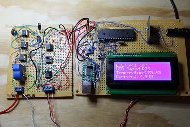
2 1/1/1 Goals Provide a cost effective mechanism for acquiring temperature and current data. Allow the operator to determine when to perform preventive maintenance. Record the temperature and current data to a host computer. Display current and temperature data on LCD Design a compact, portable, and user friendly system. Functional Requirements Measure the heat (temperature) generated by the motor. Measure the amount of current drawn by the motor. Record temperature and current data to a host computer for later analysis. Display current and temperature data on LCD display.
3 1/1/1 Specification Measured temperature shall be in the range of to degrees Fahrenheit. Measured current shall be in the range of 1 to 15 A. The temperature accuracy shall be within + degrees Fahrenheit. The current accuracy shall be within + 1 ma Both temperature and current should be transmitted to a host computer every seconds. The operating temperature shall be between and 1 degrees Fahrenheit. The system shall not exceed lbs. System Block Diagram
4 1/1/1 Subsystems Sensors module Power supply module Microcontroller module Data display module Data storage module Signal conditioning module Sensors Selection Criteria Transfer function must be linear Response time must less than 1 ms Must have great accuracy Noise level must be less than 1 mv Dynamic range must be between A and 15 A Must be easy to use

5 1/1/1 TLS 15 NP Current Sensor Type: Hall Effect Maximum measure current: 15 A Supply voltage: 5V Supply current: 1. ma Output type: voltage Response time: <1 ns Sensitivity: 1. mv/a TLS 15 NP 5

6 1/1/1 CSLACD Current Sensor Type: Hall Effect Max Current: A Supply Current:1 ua Supply Voltage: 8V 1.V Output type: Voltage Response Time:us Sensitivity:. mv/a CSLACD Sensor

7 1/1/1 Sensors (Continued) Temperature Sensor (LM) Internally calibrated Linear Output: 1mV/Degree Fahrenheit Supply Voltage: 5V to V Supply Current:5 ua Response Time:5 ms Measurement Range: 5 to Degrees Fahrenheit Accuracy: + Degrees LM Sensor
8 1/1/1 DS18 Dynamic range: to 5 Accuracy:.5 degrees Fahrenheit Resolution: 1 bits Cost: $. DS18 8
9 1/1/1 Op Amp Selection LM 1 Dual power supply Well balanced Easy to use CMP1 Single supply Requires virtual ground Hard to design Single Supply Op Amp 9
10 1/1/1 Signal Conditioning Module Temperature Sensor Signal Conditioning Circuit 5V C1 Vin.1µF U1 Vout VDD 5 V R1 15Ω RG MCP1-I/P RF R 8Ω C.1µF kω 9kΩ 1
11 1/1/1 Current Sensor Signal Conditioning Circuit Vin 5V C1.1µF U5 MCP1-I/P R 5V C.1µF U MCP1-I/P R R11 1kΩ 1.nF R1 1kΩ C 8pF C8 C9 5V.1µF U MCP1-I/P Vout R5 8Ω C.1µF R 15Ω kω VDD 5 V 9kΩ Power Supply Wall adapter Input: 11V 15V Output: 1V Current: 1A Regulator Type: LM85 Voltage: 5V Current: 1A 11

12 1/1/1 Power Supply Schematic 1NG D1 Input C1.1µF U1 LM85CT LINE VREG VOLTAGE COMMON Output C.1µF USB Communication Module FTR Controller Provides communication channel between the MCU and the host computer. Converts USB port to Virtual COM port in the host computer. Manages enumeration and other USB bus communication requirements in hardware. No USB specific firmware required. Supports Bus powered and Self powered. USB. full speed compatible. 1

13 1/1/1 USB Controller (continued) Operating temperature: to 85 degrees C. Supply voltage: 1.8V to 5.5V. Supply current: 15mA Data transfer: baud to Mbaud. USB Controller Schematic 1

14 1/1/1 Microcontroller PIC18F55 Analog to digital conversion (ADC) Process temperature and current data. Transfers temperature and current data to the host computer. Display temperature and current data on LCD display. Microcontroller Communication With USB Controller Communication With DAC Communication with LCD display 1
15 1/1/1 Microcontroller (continued) Supply voltage: V to 5.5V Supply current: 5.8 ua Sink/source current: 5mA Clock: Internal and external oscillator. Timers: ADC resolution: 1 bit Analog channels: 1 Interrupt sources: Microcontroller Schematic 15
16 1/1/1 1 System Integration U UMR U MCP1-I/P R kω R 9kΩ C.1µF C.1µF R5 8Ω R 15Ω U MCP1-I/P R11 1kΩ R1 1kΩ C 8pF C8 1.nF C9.1µF U5 MCP1-I/P C1.1µF J PJ-1A U GND CV RS RW E D D1 D D D D5 D D U8 LM85CT LINE VREG COMMON VOLTAGE D1 1NG C5.µF C.1µF D 1NG S1 Key = Space 5V U1 LTSR 15_NP J1 HDR1X 1 Isense_In Isense_Out OUT C1.1µF U MCP1-I/P R8 1kΩ R9 1kΩ C 8pF C11 1.nF C1.1µF U9 MCP1-I/P R1 kω R 1kΩ RG kω RF 1kΩ C1.1µF U1 MCP1-I/P J HDR1X 1 U11 PIC18F R 1kΩ C1 pf C15 pf X1 HC-9/U_11MHz AN AN AN1 AN1 RB RB RB RB RB1 RB1 RB RB RB5 RB5 RB RB Software Architecture
17 1/1/1 Software: Microcontroller Programming language: C Program Initialization Configure ports Configure ADC Configure USART ADC Conversion Reads data from analog channels Format data Data transfer/display Transfer data to the host computer Display data on LCD display Algorithm: Microcontroller 1


18 1/1/1 Statechart Testing and Validation 18
 $1. $. (Had it ) Capacitors 15 $9. (per kit) $9. $. (Had it) UMR USB-to- 1 $11.")
 $1. $. (purchased two years ago) Oscillator 1 $. $. $. (Had the part in my tool box) Total $9.1 $8. 19")
19 1/1/1 Testing and Validation Cost and Resource Management Part Name Quantity Price Per Unit Total Cost MCP1 Op Amp $. $. $. TLS 15-NP Current 1 $1. $1. $1. Sensor LMDZ Temperature sensor 1 $. $. $. Actual Amount of Money Spent Resistors 1 $1.(per kit) $1. $. (Had it ) Capacitors 15 $9. (per kit) $9. $. (Had it) UMR USB-to- 1 $11. $11. $1. UART Converter PIC18F55 1 $.9 $.9 $.(Had it ) Terminal Blocks $1. $. $. (removed from power supply) Barrel power Jack 1 $. $. $. (removed from an old router) Diode $. (per kit) $1. $. (purchased two years ago) Oscillator 1 $. $. $. (Had the part in my tool box) Total $9.1 $8. 19
20 1/1/1 Risks The microcontroller not sending data to PC The temperature sensor not being attached to the motor Lesson Learned Project management Planning is key to a successful project Always buy extra components in case one get damaged Gained valuable experience in analog signal conditioning Gained experience programming PIC microcontroller
21 1/1/1 Conclusion All features of the USB Based Data Acquisition System were successfully implemented The cost of designing the UBS Based Data Acquisition System was well bellow $1 Did not have enough time to focus on the project as given my work related responsibilities Overall, this was a very rewarding experience Thank you. Questions? 1
Modtronix Engineering Modular Electronic Solutions SBC28DC. Single board computer for 28 pin DIP PICs
 Modtronix Engineering Modular Electronic Solutions Single board computer for 28 pin DIP PICs Table of Contents 1 Introduction...2 2 Features...4 3 Expansion Connectors...5 3.1 Daughter Board Connectors...5
Introduction to Mechatronics and the Mechatronic Design Center Microchip Technology Incorporated. All Rights Reserved. 1
 Introduction to Mechatronics and the Mechatronic Design Center 2005 Microchip Technology Incorporated. All Rights Reserved. 1 What is Mechatronics? Implementing electronic controls in a mechanical system
SUB-SYSTEM BOARD 5562 Campbell (MAXREFDES4#): 16-Bit High-Accuracy 4-20mA Input Isolated Analog Front End (AFE)
: 16-Bit High-Accuracy 4-20mA Input Isolated Analog Front End (AFE)") Maxim > Design Support > Technical Documents > Sub-System Boards > APP 5562 Keywords: Campbell, MAXREFDES4, subsystem reference design, analog front end, AFE, industrial sensors, isolated power and data,
Maxim > Design Support > Technical Documents > Sub-System Boards > APP 5562 Keywords: Campbell, MAXREFDES4, subsystem reference design, analog front end, AFE, industrial sensors, isolated power and data,
ACU6. Technical Reference Manual. Specifications Interfacing Dimensions. Document topics. ANSARI Controller Unit Type 6 technical reference manual
 ACU6 Technical Reference Manual ANSARI Controller Unit Type 6 technical reference manual Document topics Specifications Interfacing Dimensions Document Version: 1.03 13. January 2013 By ANSARI GmbH Friedrich-Ebert-Damm
Downloaded from Elcodis.com electronic components distributor
 CONTENTS LV24-33A KEY FEATURES 4 CONNECTING THE SYSTEM 5 INTRODUCTION 6 Switches and Jumpers 7 MCU Sockets 8 Power Supply 10 On-board USB 2.0 Programmer 11 RS-232 Communication Circuit 12 LEDs 14 Push
SBC65EC. Ethernet enabled Single Board Computer
 Ethernet enabled Single Board Computer Table of Contents 1 Introduction...2 2 Features...3 3 Daughter Board Connectors...4 3.1 As a Daughter Board...5 3.2 Expansion boards...5 4 Interfaces...5 4.1 Ethernet...5
Section 30. In-Circuit Serial Programming (ICSP )
") Section 30. In-Circuit Serial Programming (ICSP ) HIGHLIGHTS This section of the manual contains the following major topics: 30. Introduction... 30-2 30.2 Entering In-Circuit Serial Programming Mode...
Section 30. In-Circuit Serial Programming (ICSP ) HIGHLIGHTS This section of the manual contains the following major topics: 30. Introduction... 30-2 30.2 Entering In-Circuit Serial Programming Mode...
SBC44EC. Single board computer for 44 pin PLCC PICs
 Single board computer for 44 pin PLCC PICs Table of Contents 1 Introduction...2 2 Features...3 3 Expansion Connectors...4 3.1 Frontend Connectors...4 3.1.1 Connecting IDC connectors to the Frontend Connector...5
EasyPIC5 Development System
 EasyPIC5 Development System Part No.: MPMICRO-PIC-Devel- EasyPIC5 Overview EasyPIC5 is a development system that supports over 120 8-, 14-, 18-, 20-, 28- and 40-pin PIC MCUs. EasyPIC5 allows PIC microcontrollers
EasyAVR6 Development System
 EasyAVR6 Development System Part No.: MPMICRO-AVR-Devel-EasyAVR6 Overview EasyAVR6 is a development system that supports a wide range of 8-, 14-, 20-, 28- and 40-pin AVR MCUs. EasyAVR6 allows AVR microcontrollers
EK307 Lab: Microcontrollers
 EK307 Lab: Microcontrollers Laboratory Goal: Program a microcontroller to perform a variety of digital tasks. Learning Objectives: Learn how to program and use the Atmega 323 microcontroller Suggested
Bolt 18F2550 System Hardware Manual
 1 Bolt 18F2550 System Hardware Manual Index : 1. Overview 2. Technical specifications 3. Definition of pins in 18F2550 4. Block diagram 5. FLASH memory Bootloader programmer 6. Digital ports 6.1 Leds and
CONTENTS. dspicpro4 KEY FEATURES 4 CONNECTING THE SYSTEM 5 INTRODUCTION 6
 CONTENTS dspicpro4 KEY FEATURES 4 CONNECTING THE SYSTEM 5 INTRODUCTION 6 Switches and Jumpers 7 MCU Sockets 8 Power Supply 10 On-Board USB 2.0 Programmer 11 MikroICD 12 RS-232 Communication Circuit 13
EEE394 Microprocessor and Microcontroller Laboratory Lab #6
 Exp. No #6 Date: INTERRUPTS AND ADC IN PIC MICROCONTROLLER OBJECTIVE The purpose of the experiment is to configure external interrupt and the ADC in PIC microcontrollers. (i) To flip the LED connected
ILI2511. ILI2511 Single Chip Capacitive Touch Sensor Controller. Specification ILI TECHNOLOGY CORP. Version: V1.4. Date: 2018/7/5
 Single Chip Capacitive Touch Sensor Controller Specification Version: V1.4 Date: 2018/7/5 ILI TECHNOLOGY CORP. 8F., No.1, Taiyuan 2 nd St., Zhubei City, Hsinchu County 302, Taiwan (R.O.C.) Tel.886-3-5600099;
AN5181. Building a thermometer using the STM8 Nucleo-64 boards. Application note. Introduction
 Application note Building a thermometer using the STM8 Nucleo-64 boards Introduction The NUCLEO-8S208RB (built around the STM8S208RBT6 device) and the NUCLEO-8L152R8 (built around the STM8L152R8T6 device)
DEV16T. LCD Daughter board
 LCD Daughter board Table of Contents 1 Introduction...2 2 Features...3 3 Expansion Connectors...4 3.1 Daughter Board Connectors...4 4 LCD Display...5 5 Input Buttons S1 to S4...5 6 Buzzer...5 7 Connector
SBC45EC. Single board computer for 44 pin PLCC PICs
 Single board computer for 44 pin PLCC PICs Table of Contents 1 Introduction...3 2 Features...4 3 Expansion Connectors...5 3.1 Frontend Connectors...5 3.1.1 Connecting IDC connectors to the Frontend Connector...5
Variable Power Supply Digital Control Circuit Diagram Using Lm317
 Variable Power Supply Digital Control Circuit Diagram Using Lm317 DIGITAL POWER SUPPLY USING LM317 A Major Project Report Submitted partial fulfillment of the requirement for the award of the Degree of
PWR-I/O-DB Power and I/O Daughterboard (#28301)
") Web Site: www.parallax.com Forums: forums.parallax.com Sales: sales@parallax.com Technical: support@parallax.com Office: (916) 624-8333 Fax: (916) 624-8003 Sales: (888) 512-1024 Tech Support: (888) 997-8267
Web Site: www.parallax.com Forums: forums.parallax.com Sales: sales@parallax.com Technical: support@parallax.com Office: (916) 624-8333 Fax: (916) 624-8003 Sales: (888) 512-1024 Tech Support: (888) 997-8267
PICado Alpha Development Board V1.0
 V1.0 Bluetooth Transceiver Module HC-05 Four onboard FET power output stage 34 freely assignable I/O pins ICSP interface 2015 Jan Ritschard, All rights reserved. V1.0 Table of Contents 1. Introduction...
Developement of Multi Interface Board for Educational Trainer Kit
 Journal of Engineering Technology Vol. 2(1): 1-5, 2012 ISSN 2231-8798 2012UniKLBMI Developement of Multi Interface Board for Educational Trainer Kit M.R. Abdullah, Z. Zaharudin, Z. Mahmoodin, Z. Zainuddin
2 in 1. EasyAVR4 User s Manual AVR. MikroElektronika. Software and Hardware solutions for Embedded World
 SOFTWARE AND HARDWARE SOLUTIONS FOR THE EMBEDDED WORLD - Books - Compilers User s Manual 2 in 1 2.0 IN-CIRCUIT PROGRAMMER ATMEL AVR DEVELOPMENT BOARD With useful implemented peripherals, plentiful practical
AL3159 Evaluation Module
 Device Features Description V IN Range: 2.7V to 5.5V Up to 93% Max Power Efficiency 1% Current Matching Accuracy Between Channels Three Simple Logic Decoding LED On/Off Control Inputs Low Transition Threshold
BG2D Solderless Connection Gate Drive Prototype Board
 Application NOTES: First Release: May, 2008 BG2D Solderless Connection Gate Drive Prototype Board Description: The BG2D is a two channel gate drive circuit for that the dual NX series modules pins plug
S USB-PC Connection (Cable Not Included) S USB Powered (No External Power Supply Required) S Real-Time Data Acquisition Through the USB
 S USB Powered (No External Power Supply Required) S Real-Time Data Acquisition Through the USB") 19-5610; Rev 1; 8/11 MAXADClite Evaluation Kit General Description The MAXADClite evaluation kit (EV kit) evaluates the MAX11645, Maxim's smallest, very-low-power, 12-bit, 2-channel analog-to-digital converter
19-5610; Rev 1; 8/11 MAXADClite Evaluation Kit General Description The MAXADClite evaluation kit (EV kit) evaluates the MAX11645, Maxim's smallest, very-low-power, 12-bit, 2-channel analog-to-digital converter
Embedded Systems and Software
 Embedded Systems and Software Lecture 12 Some Hardware Considerations Hardware Considerations Slide 1 Logic States Digital signals may be in one of three states State 1: High, or 1. Using positive logic
ILI2303. ILI2303 Capacitive Touch Sensor Controller. Specification
 Capacitive Touch Sensor Controller Specification Version: V1.03 Date: 2014/9/17 ILI TECHNOLOGY CORP. 8F, No.38, Taiyuan St., Jhubei City, Hsinchu County 302, Taiwan, R.O.C. Tel.886-3-5600099; Fax.886-3-5600055
HARDWARE MANUAL TMCM-1613 TMCM-1613-REC. Hardware Version V TRINAMIC Motion Control GmbH & Co. KG Hamburg, Germany.
 MODULES FOR BLDC MOTORS MODULES Hardware Version V 1.10 HARDWARE MANUAL + + TMCM-1613 + + Single Axis BLDC Controller / Driver Block-commutation Hall-sensor based Analog+digital inputs / outputs Up-to
AVR Intermediate Development Board. Product Manual. Contents. 1) Overview 2) Features 3) Using the board 4) Troubleshooting and getting help
 Overview 2) Features 3) Using the board 4) Troubleshooting and getting help") AVR Intermediate Development Board Product Manual Contents 1) Overview 2) Features 3) Using the board 4) Troubleshooting and getting help 1. Overview 2. Features The board is built on a high quality FR-4(1.6
AVR Intermediate Development Board Product Manual Contents 1) Overview 2) Features 3) Using the board 4) Troubleshooting and getting help 1. Overview 2. Features The board is built on a high quality FR-4(1.6
User Manual For CP-JR ARM7 USB-LPC2148 / EXP
 CP-JR ARM7 USB-LPC2148 / EXP 38 CR-JR ARM7 USB-LPC2148 which is a Board Microcontroller ARM7TDMI-S Core uses Microcontroller 16/32-Bit 64 Pin as Low Power type to be a permanent MCU on board and uses MCU
CSE 466 Exam 1 Winter, 2010
 This take-home exam has 100 points and is due at the beginning of class on Friday, Feb. 13. (!!!) Please submit printed output if possible. Otherwise, write legibly. Both the Word document and the PDF
LABORATORY MANUAL Interfacing LCD 16x2, Keypad 4x4 and 7Segment Display to PIC18F4580
 LABORATORY MANUAL Interfacing LCD 16x2, Keypad 4x4 and 7Segment Display to PIC18F458 1. OBJECTIVES: 1.1 To learn how to interface LCD 16x2, Keypad 4x4 and 7Segment Display to the microcontroller. 1.2 To
Ocean Controls KTA-224 Modbus IO Module
 Ocean Controls Ocean Controls 8 Relay outputs (5A, 250VAC contacts) 4 Opto-Isolated Inputs with counters 3 Analog Inputs (10 bit) jumperselectable for 0-5V or 0-20mA 4 Input Counters RS485 or USB (virtual
TP6836. USB 2.4G RF Dongle. Data Sheet
 TP6836 Data Sheet tenx reserves the right to change or discontinue the manual and online documentation to this product herein to improve reliability, function or design without further notice. tenx does
Application Suggestions for X2Y Technology
 Application Suggestions for X2Y Technology The following slides show applications that would benefit from balanced, low inductance X2Y devices. X2Y devices can offer a significant performance improvement
CONTENTS BIGAVR2 KEY FEATURES 4 CONNECTING THE SYSTEM 5 INTRODUCTION 6
 CONTENTS BIGAVR2 KEY FEATURES 4 CONNECTING THE SYSTEM 5 INTRODUCTION 6 Switches 7 Jumpers 8 MCU Sockets 9 Power Supply 11 On-board USB 2.0 Programmer 12 Oscillator 14 LEDs 15 Reset Circuit 17 Push-buttons
BIG8051. Development system. User manual
 BIG8051 User manual All s development systems represent irreplaceable tools for programming and developing microcontroller-based devices. Carefully chosen components and the use of machines of the last
A variety of ECONseries modules provide economical yet flexible solutions. Waveform Generation
 ECONseries BUS: USB Type: Economy, Mini-Instruments ECONseries Economy USB Mini-Instruments Flexible Yet Economical A variety of low-cost ECONseries modules are available to provide flexible yet economical
IMPROVING PROCESS CONTROL APPLICATIONS BY USING IP COMMUNICATIONS
 7 th International Conference on DEVELOPMENT AND APPLICATION SYSTEMS S u c e a v a, R o m a n i a, M a y 27 29, 2 0 0 4 IMPROVING PROCESS CONTROL APPLICATIONS BY USING IP COMMUNICATIONS Eugen COCA University
MIDI CPU Hardware Rev K. User Manual
 MIDI CPU Hardware Revision K User Manual Updated 2010-09-08 Additional documentation available at: http://highlyliquid.com/support/ Page 1 / 18 Table of Contents 1.0 Important Safety Information...2 2.0
2. Control Pin Functions and Applications
 IMARY CONTROL ( PIN) Module Enable / Disable. The module can be disabled by pulling the below 2.3 V with respect to the Input. This should be done with an open-collector transistor, relay, or optocoupler.
DEV-1 HamStack Development Board
 Sierra Radio Systems DEV-1 HamStack Development Board Reference Manual Version 1.0 Contents Introduction Hardware Compiler overview Program structure Code examples Sample projects For more information,
RS232-ADC16/24 Manual
 RS232-ADC16/24 Manual Version 1.11 Copyright taskit GmbH 2009 www.taskit.de Page 1/22 Table of contents 1 Features...3 2 Introduction...3 3 Bringing into service...4 4 Application Sample...5 5 Frame layout...6
CURRENT SOURCE FOR LED MODULES
 CURRENT SOURCE FOR LED MODULES 100 ma 2000 ma 01/2018 ATEsystem s.r.o. Studentska 6202/17 708 00 Ostrava-Poruba Czech Republic M +420 595 172 720 E atesystem@atesystem.cz W www.atesystem.cz DOCUMENT INFORMATION
AKKON USB CONTROLLER BOARD
 TN002 AKKON USB CONTROLLER BOARD USB Microcontroller board with the PIC18F4550 * Datasheet Authors: Gerhard Burger Version: 1.0 Last update: 20.01.2006 File: Attachments: no attachments Table of versions
Evaluation Board for AD5590 EVAL-AD5590
 Evaluation Board for AD5590 EVAL-AD5590 FEATURES Full-featured evaluation board for the AD5590 USB interface PC software for register programming Various reference voltages available Standalone operation
Embedded Navigation Solutions VN 100, VN 200 & VN 300 Development Board User Manual
 Embedded Navigation Solutions VN 100, VN 200 & VN 300 Development Board User Manual VectorNav Technologies Contact Info 10501 Markison Road Phone +1 512 772 3615 Dallas, Texas 75238 Email support@vectornav.com
Figure 1.1: Some embedded device. In this course we shall learn microcontroller and FPGA based embedded system.
 Course Code: EEE 4846 International Islamic University Chittagong (IIUC) Department of Electrical and Electronic Engineering (EEE) Course Title: Embedded System Sessional Exp. 1: Familiarization with necessary
8051 Intermidiate Development Board. Product Manual. Contents. 1) Overview 2) Features 3) Using the board 4) Troubleshooting and getting help
 Overview 2) Features 3) Using the board 4) Troubleshooting and getting help") 8051 Intermidiate Development Board Product Manual Contents 1) Overview 2) Features 3) Using the board 4) Troubleshooting and getting help 1. Overview 2. Features The board is built on a high quality FR-4(1.6
8051 Intermidiate Development Board Product Manual Contents 1) Overview 2) Features 3) Using the board 4) Troubleshooting and getting help 1. Overview 2. Features The board is built on a high quality FR-4(1.6
eip-24/100 Embedded TCP/IP 10/100-BaseT Network Module Features Description Applications
 Embedded TCP/IP 10/100-BaseT Network Module Features 16-bit Microcontroller with Enhanced Flash program memory and static RAM data memory On board 10/100Mbps Ethernet controller, and RJ45 jack for network
Group 10 Programmable Sensor Output Simulator Progress Report #2
 Department of Electrical Engineering University of Victoria ELEC 499 Design Project Group 10 Programmable Sensor Output Simulator Progress Report #2 March 5, 2005 Submitted by: Group No.: 10 Team: Exfour
Introduction to Microcontroller Apps for Amateur Radio Projects Using the HamStack Platform.
 Introduction to Microcontroller Apps for Amateur Radio Projects Using the HamStack Platform www.sierraradio.net www.hamstack.com Topics Introduction Hardware options Software development HamStack project
Exclusive 2.5 GHz Frequency Counter
 Exclusive 2.5 GHz Frequency Counter with blue 2 x 16 LCD display This manual will guide you how to assemble, test and tune this frequency counter KIT. Features: Frequency range from 5 MHz to 2.5GHz Factory
PIC Microcontroller Introduction
 PIC Microcontroller Introduction The real name of this microcontroller is PICmicro (Peripheral Interface Controller), but it is better known as PIC. Its first ancestor was designed in 1975 by General Instruments.
Capacitive Touch Remote Control Reference Design User s Guide
 Capacitive Touch Remote Control Reference Design User s Guide Microchip Korea V0.8-page 1 Capacitive Touch Remote Control Reference Design User s Guide Table of Contents Chapter 1. Introduction 1.1 Introduction
GPRS based SCADA implementation for multisensory security with SMS alerts.
 GPRS based SCADA implementation for multisensory security with SMS alerts. Priyanka somashekhar malabagi 1, Latha shenoy 2 M.Tech Student, Microelectronics and Control Systems, NMAM Institute of Technology,
EE445L Fall 2016 Quiz 2A Solution Page 1
 EE445L Fall 2016 Quiz 2A Solution Page 1 Jonathan W. Valvano First: Last: Solution November 18, 2016, 10:00-10:50am. Open book, open notes, calculator (no laptops, phones, devices with screens larger than
USB 1608G Series USB Multifunction Devices
 USB Multifunction Devices Features 16-bit high-speed USB devices Acquisition rates ranging from 250 ks/s to 500 ks/s differential (DIFF) or 16 singleended (SE) analog inputs (softwareselectable) Up to
MAXREFDES82#: SMART FORCE SENSOR
 System Board 6266 MAXREFDES82#: SMART FORCE SENSOR Maxim s MAXREFDES82# features a next generation industrial, smart force sensor. Mounted on a quadrant of load cells channeled into a multi-channel, 24-bit
Explorer V1.20. Features
 V1.20 Multi-function USB I/O Expander and Controller Features Dual h-bridge 1.3A motor drive with PWM speed control 4.6V to 10.8V input range USB communication 4x digital inputs 2x analogue inputs 7x 100mA
Datacorder Kit MitchElectronics 2019
 Datacorder Kit MitchElectronics 2019 www.mitchelectronics.co.uk CONTENTS Schematic 3 How It Works 4 How To Use 5 Materials 6 Construction 7 Important Information 8 Page 2 SCHEMATIC Page 3 HOW IT WORKS
EE445L Fall 2018 Final EID: Page 1 of 7
 EE445L Fall 2018 Final EID: Page 1 of 7 Jonathan W. Valvano First: Last: This is the closed book section. Calculator is allowed (no laptops, phones, devices with wireless communication). You must put your
Lecture (02) PIC16F84 (I)
 PIC16F84 (I)") Lecture (02) PIC16F84 (I) By: Dr. Ahmed ElShafee ١ Review of Memory Technologies The PIC 16 Series PIC 16F84A The PIC 16F84A Memory The Oscillator Instruction Cycle Power up and Reset Parallel ports Technical
Lecture (02) PIC16F84 (I) By: Dr. Ahmed ElShafee ١ Review of Memory Technologies The PIC 16 Series PIC 16F84A The PIC 16F84A Memory The Oscillator Instruction Cycle Power up and Reset Parallel ports Technical
RN-174. WiFly GSX Super Module. Features. Description. Applications. rn-174-ds v1.1 4/20/2011
 www.rovingnetworks.com rn-174-ds v1.1 4/20/2011 WiFly GSX Super Module Features Development board containing the RN-171 module, status LEDs, power regulator Supports chip antenna (-C), PCB Trace antenna
2 in 1. BigAVR User s Manual AVR. MikroElektronika. Software and Hardware solutions for Embedded World
 SOFTWARE AND HARDWARE SOLUTIONS FOR THE EMBEDDED WORLD - Books - Compilers User s Manual 2 in 1 USB 2.0 IN-CIRCUIT PROGRAMMER ATMEL AVR DEVELOPMENT BOARD With useful implemented peripherals, plentiful
Rapid40i PIC Prototyping PCB User Manual
 Description This is a PCB designed to facilitate the rapid prototyping of a device based on a 40 pin Microchip PIC microcontroller. To allow users to focus on their application, we take care of key housekeeping
Four-Channel Universal Analog Input Using the MAX11270
 Four-Channel Universal Analog Input Using the MAX70 MAXREFDES5 Introduction The MAXREFDES5 is a four-channel universal analog input that measures voltage or current signals. Each channel can be configured
VINCULUM-BASED TEMPERATURE / HUMIDITY / VOLTAGE DATA LOGGER FEATURES:
 DLP-VLOG *LEAD-FREE* VINCULUM-BASED TEMPERATURE / HUMIDITY / VOLTAGE DATA LOGGER FEATURES: Virtually Unlimited Data Storage Utilizing FTDI s New Vinculum USB Host IC Data Logged to USB Flash Drive Low-Power
BG1B Universal Gate Drive Prototype Board
 BG1B Universal Gate Drive Prototype Board Description: The BG1B is a single channel gate drive circuit board for high power IGBT modules. The BG1B utilizes Powerex hybrid gate drivers and DC-to-DC converters
UNIT 3 THE 8051-REAL WORLD INTERFACING
 UNIT 3 THE 8051-REAL WORLD INTERFACING 8031/51 INTERFACING TO EXTERNAL MEMORY The number of bits that a semiconductor memory chip can store is called chip capacity It can be in units of Kbits (kilobits),
TP6825. USB Full Speed Game Pad Controller. Data Sheet. Tenx reserves the right to change or discontinue this product without notice.
 Advance Information TP6825 USB Full Speed Game Pad Controller Data Sheet Tenx reserves the right to change or discontinue this product without notice. tenx technology, inc. Contain 1. GENERAL DESCRIPTION...
EVAL-INAMP-62RZ/82RZ/82RMZ
 Evaluation Boards for the AD620 Series and and the AD8220 Series Instrumentation Amplifiers EVAL-INAMP-62RZ/82RZ/82RMZ FEATURES 3 generic, easy-to-use PC boards Support several related in-amp products
USB-Based 14-Channel Data-Acquisition Module
 USB-Based -Channel Data-Acquisition Module DLP-IO LEAD FREE FEATURES: IO s: 0- Analog, Digital In/Out, Temperature Two Bipolar Analog Inputs; ± Input Range Max All Analog Inputs: Up to 0Ksps Sample Rate
BIGdsPIC6. Development System. User manual
 BIGdsPIC6 User manual All s development systems represent irreplaceable tools for programming and developing microcontroller-based devices. Carefully chosen components and the use of machines of the last
ILI2312. ILI2312 Single Chip Capacitive Touch Sensor Controller. Specification ILI TECHNOLOGY CORP. Version: V1.03.
 Single Chip Capacitive Touch Sensor Controller Specification Version: V1.03 Date: 2015/11/17 ILI TECHNOLOGY CORP. 8F, No.38, Taiyuan St., Jhubei City, Hsinchu County 302, Taiwan, R.O.C. Tel.886-3-5600099;
PVK40. User's manual. Feature Rich Development and Educational Kit for 40-pin Microchip PIC microcontrollers
 PVK40 User's manual Feature Rich Development and Educational Kit for 40-pin Microchip PIC microcontrollers CONTENTS PVK40 3 On-board peripherals: 3 Power supply 4 Microcontroller 4 Reset circuitry 4 Oscilator
Mini-TNC Rev 0711 is designed exclusively to work as an APRS TNC.
 Fox Delta Amateur Radio Projects & Kits Mini-TNC Technical Details and Schematic: Mini-TNC - A 1200-Baud Packet TNC Rev. 0711 Completed Mini-TNC: Mini-TNC Rev 0711 is designed exclusively to work as an
TS04. 4-Channel Self Calibration Capacitive Touch Sensor SPECIFICATION V2.0
 TS4 4-Channel Self Calibration Capacitive Touch Sensor SPECIFICATION V2. Specification TS4 (4-CH Auto Sensitivity Calibration Capacitive Touch Sensor). General Feature 4-Channel capacitive sensor with
EZ-Bv4 Datasheet v0.7
 EZ-Bv4 Datasheet v0.7 Table of Contents Introduction... 2 Electrical Characteristics... 3 Regulated and Unregulated Power Pins... 4 Low Battery Warning... 4 Hardware Features Main CPU... 5 Fuse Protection...
USB Debug Adapter. Power USB DEBUG ADAPTER. Silicon Laboratories. Stop. Run. Figure 1. Hardware Setup using a USB Debug Adapter
 C8051F38X DEVELOPMENT KIT USER S GUIDE 1. Kit Contents The C8051F38x Development Kit contains the following items: C8051F380 Target Board C8051Fxxx Development Kit Quick-start Guide Silicon Laboratories
Isolated, Field Configurable Analog Input 6B11 / 6B11HV FEATURES APPLICATIONS PRODUCT OVERVIEW
 Isolated, Field Configurable Analog Input 6B11 / 6B11HV FEATURES Single-channel isolated signal-conditioning modules. Accepts outputs from Thermocouple, millivolt, volt and current signals. Complete microcomputer-based
GRAVITECH GROUP
 GRAVITECH.US uresearch GRAVITECH GROUP Description The I2C-ADC board is a 14-pin CMOS device that provides 8-CH, 12-bit of Analog to Digital Converter (ADC) using I 2 C bus. There are no external components
DIGITAL COMPASS SOLUTION
 Features 5 Heading Accuracy, 0.5 Resolution 2-axis Capability Small Size (19mm x 19mm x 4.5mm), Light Weight Advanced Hard Iron Calibration Routine for Stray Fields and Ferrous Objects 0 to 70 C Operating
AIAO U CompactPCI Analog I/O Card. User Manual. 13 Altalef St. Yehud, Israel Tel: 972 (3) Fax: 972 (3)
 Fax: 972 (3)") AIAO-0700 3U CompactPCI Analog I/O Card User Manual 13 Altalef St. Yehud, Israel 56216 Tel: 972 (3) 632-0533 Fax: 972 (3) 632-0458 www.tenta.com 919 Kifer Road Sunnyvale, CA 94086 USA Tel: (408) 328-1370
AIAO-0700 3U CompactPCI Analog I/O Card User Manual 13 Altalef St. Yehud, Israel 56216 Tel: 972 (3) 632-0533 Fax: 972 (3) 632-0458 www.tenta.com 919 Kifer Road Sunnyvale, CA 94086 USA Tel: (408) 328-1370
The FED PIC Flex 2 Development Boards
 The FED PIC Flex 2 Development Boards THE FED PIC Flex Development board offers a host for 28 or 40 pin devices and includes LED's, switches, transistor switches, USB interface, serial port, support circuitry,
A Micropower, 2-channel, ksps, Serial-Output 12-bit SAR ADC
 A Micropower, 2-channel, 187.5-ksps, Serial-Output 12-bit SAR ADC FEATURES Quick and easy Interface to computer for evaluation via Touchstone Viperboard and USB cable Input BNC connection On-board +3.3V
Environmental Data Acquisition Using (ENC28J60)
") Environmental Data Acquisition Using (ENC28J60) Joshi Vaibhav Abstract -- Ethernet is a local area technology, which is used for reliable and efficient transfer and access of information across the devices
Environmental Data Acquisition Using (ENC28J60) Joshi Vaibhav Abstract -- Ethernet is a local area technology, which is used for reliable and efficient transfer and access of information across the devices
RFID: Read and Display V2010. Version 1.1. Sept Cytron Technologies Sdn. Bhd.
 PR8-B RFID: Read and Display V2010 Version 1.1 Sept 2010 Cytron Technologies Sdn. Bhd. Information contained in this publication regarding device applications and the like is intended through suggestion
Wall Industries SMPS and Microcontrollers
 Wall Industries SMPS and Microcontrollers Introduction Wall Industries commitment to the latest technologies is evident in its recent announcement to add microcontrollers to their already advanced designs.
RN-174 WiFly Super Module
 RN- WiFly Super Module Features Evaluation board for the RN- module Supports chip antenna (RN--C), PCB trace antenna (RN--P), wire antenna (RN--W), and U.FL connector for an external antenna (RN--U) Ultra-low
USB 1608G Series USB Multifunction Devices
 USB Multifunction Devices Features 16-bit high-speed USB devices Acquisition rates ranging from 250 ks/s to 500 ks/s differential (DIFF) or 16 singleended (SE) analog inputs (softwareselectable) Up to
ECE 480 Team 5 Introduction to MAVRK module
 ECE 480 Team 5 Introduction to MAVRK module Team Members Jordan Bennett Kyle Schultz Min Jae Lee Kevin Yeh Definition of MAVRK Component of MAVRK starter Kit Component of umavrk Module design procedure
Lab-3: LCDs Serial Communication Analog Inputs Temperature Measurement System
 Mechatronics Engineering and Automation Faculty of Engineering, Ain Shams University MCT-151, Spring 2015 Lab-3: LCDs Serial Communication Analog Inputs Temperature Measurement System Ahmed Okasha okasha1st@gmail.com
Set Up a PLL Loop Filter on the ez80f91 MCU
 Application Note Set Up a PLL Loop Filter on the ez80f91 MCU AN017504-0108 Abstract This document provides information that will help an application developer effectively use the ez80f91 MCU s on-chip
Mega128-DEVelopment Board Progressive Resources LLC 4105 Vincennes Road Indianapolis, IN (317) (317) FAX
 (317) FAX") Mega128-DEVelopment Board Progressive Resources LLC 4105 Vincennes Road Indianapolis, IN 46268 (317) 471-1577 (317) 471-1580 FAX http://www.prllc.com GENERAL The Mega128-Development board is designed for
Mega128-DEVelopment Board Progressive Resources LLC 4105 Vincennes Road Indianapolis, IN 46268 (317) 471-1577 (317) 471-1580 FAX http://www.prllc.com GENERAL The Mega128-Development board is designed for
Digitally Controlled Potentiometers
 Digitally Controlled Potentiometers Jim McCreary Ph.D., VP Technology 2004/12/23 icor Proprietary Information 1 JM Outline: Digitally Controlled Potentiometers DCP Fundamentals Existing DCP Family 1024
3 in 1 ICD. EASYdsPIC4 User s Manual. MikroElektronika. Software and Hardware solutions for Embedded World
 SOFTWARE AND HARDWARE SOLUTIONS FOR THE EMBEDDED WORLD - Books - Compilers EASYdsPIC4 User s Manual mikro 3 in 1 IN-CIRCUIT DEBUGGER MICROCHIP dspic DEVELOPMENT BOARD USB 2.0 IN-CIRCUIT PROGRAMMER With
Sierra Radio Systems. HamStack. Project Board Reference Manual V1.0
 Sierra Radio Systems HamStack Project Board Reference Manual V1.0 Welcome HamStack Project Board Reference Manual Revision 1.0.3 2011 George Zafiropoulos, KJ6VU and John Best, KJ6K This guide provides
Display Real Time Clock (RTC) On LCD. Version 1.2. Aug Cytron Technologies Sdn. Bhd.
 On LCD. Version 1.2. Aug Cytron Technologies Sdn. Bhd.") Display Real Time Clock (RTC) On LCD PR12 Version 1.2 Aug 2008 Cytron Technologies Sdn. Bhd. Information contained in this publication regarding device applications and the like is intended through suggestion
Display Real Time Clock (RTC) On LCD PR12 Version 1.2 Aug 2008 Cytron Technologies Sdn. Bhd. Information contained in this publication regarding device applications and the like is intended through suggestion