System Description. System Hitch Control. powersolutions.danfoss.com
|
|
|
- Phyllis Parrish
- 6 years ago
- Views:
Transcription


1 System Description System powersolutions.danfoss.com
2 Revision history Table of revisions Date Changed Rev July 2017 Updated recommended suppliers summary 0202 August 2015 Converted to Danfoss layout BA December 2008 AA 2 Danfoss July AB en-US0202
3 Contents Overview System details Control options Hardware components Application software Features and benefits About this document...4 Referenced product specific documents...4 Microcontroller... 4 Valves...4 Software...4 System start-up procedures... 4 Latest version of technical literature...4 PLUS+1 electronic controls responsibility... 4 Hitch positioning control concepts... 4 Closed loop work control modes...6 Combination of position, force and slip control...6 Adaptive force control...6 Fast down control... 6 In-cab control from HMI...6 Remote operation...7 Closed loop transport modes...7 Rear hitch active damping...7 Front hitch active damping...7 Overview...8 PVBZ double-acting actuator control... 8 PVBZ-HS single-acting actuator control...8 PVBZ-HD single and double-acting actuator control...9 Hitch valves Sensors...10 Draft sensors for force control Angle sensor for displacement control Ground speed radar...10 Microcontrollers PLUS+1 controller power supply specification MC024-01A controller for 10 Vdc draft sensors...10 HWD for PLUS+1 controllers Application block software description...11 PLUS+1 GUIDE PLUS+1 Service Tool...11 PLUS+1 Service Tool functions...11 Keyed PLUS+1 application block software and application hardware Customer access to the Hitch application block Application file contents...11 Application file download and installation in GUIDE Standard features...12 Optional features Benefits Danfoss July AB en-US0202 3
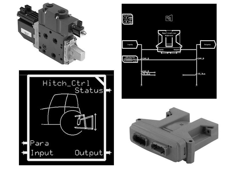
4 Overview About this document This document provides general information about the PLUS+1 System application block. In addition, it is a reference tool for vehicle OEM design, engineering, and service personnel. This document is one of several sources of technical information for the hitch control system. Other sources of technical information include individual product data sheets and application block manuals, PLUS+1 GUIDE User Manual, and PLUS+1 Service Tool User Manual. Referenced product specific documents Microcontroller PLUS+1 Controller Family Technical Information, 520L0719 PLUS+1 MC024-01A Controller Data Sheet, Valves PVG Proportional Valves Brochure, 520L0690 PVG 32 Proportional Valves Technical Information, 520L0344 Basic Module Type PVBZ Valve (hitch double-acting) Data Sheet, 520L0681 Basic Module Type PVBZ-HS Valve (hitch single-acting) Data Sheet, 520L0956 Basic Module Type PVBZ-HD Valve (hitch double-acting) Data Sheet, Software PLUS+1 GUIDE Data Sheet, 520L0708 PLUS+1 GUIDE User Manual, PLUS+1 Service Tool User Manual, 520L0899 Application Block User Manual, System start-up procedures Recommended System Start-up Procedures Technical Information, Latest version of technical literature Danfoss product literature is online at: PLUS+1 electronic controls responsibility The manufacturer of a machine or vehicle using PLUS+1 electronic controls is responsible for correctly applying and programming GUIDE-programmable PLUS+1 products. Danfoss strongly recommends that the OEM perform a system-level Failure Mode Effects Analysis (FMEA). You can find additional information about OEM responsibilities in the: PLUS+1 Controller Family Technical Information, 520L0719 Recommended System Start-up Procedures Technical Information, Hitch positioning control concepts The purpose of the hitch control system is to allow the operator to position the hitch linkage either in a work or transport position. Set points for transport and work are adjustable parameters. A closed loop position control compares the set-point to the actual input from the position sensor. If there is a difference, it controls the valve to lower or raise the linkage. The goal of an automated hitch control system is to: 4 Danfoss July AB en-US0202
5 Overview Facilitate fast and easy attachment of implements to the tractor Optimize the tractor implement output during field operation as measured in acres/hour or fuel consumption/acres relative to manually controlled systems Provide a safer and more comfortable transport of the implement between field operations Typical rear hitch Angle sensor placement Transport mode with active damping Work mode: Lift/ lower around lower reference setting Lift Draft sensor placement Force Lower 3513 Danfoss July AB en-US0202 5
6 System details Closed loop work control modes When the operator chooses work control mode, the position control adjusts the linkage to the depth reference set point. Combination of position, force and slip control In work position it is not always possible for the tractor to do the job with the specified set point. Therefore different sensors in the system collect information about the pull force and the wheel slip. The system compares these inputs with an operator defined preset maximum value. If the current pull force or wheel slip are higher than the preset maximum value, it calculates a delta and adds to the set point for the work position. When the set point is increased, the pull force/wheel slip decreases, and causes recalculation of the delta. In this way, the system continually modulates the linkage position according to the sensor inputs. Combined position, force and slip control OEM supplied Danfoss Hitch Application Block Human Machine Interface (HMI) Raising and lowering speed Active damping Speed scaling ramp deadband Danfoss Valve Reference setpoint Set-point creation and position control Force control OEM supplied Feedback sensors Slip control 3514 Adaptive force control It is sometimes difficult for the operator to find the correct parameter settings for force control in some work situations. Selecting adaptive force control allows the system to automatically adjust to changing field conditions. Fast down control This mode gets the implement more quickly to the correct working depth. Single acting: This mode bypasses the closed loop control and sends the valve to maximum lowering. Maximum lowering is still subject to scale function according to implement weight, to avoid hazardous lowering speeds. Double acting: This mode maintains the closed loop control. The only difference to work mode is that the digital output to switch between single and double acting, is set for double acting operation. In-cab control from HMI You can expand the Human Machine Interface (HMI) with up/down buttons or a joystick for manual operation. In manual operation the operator gives direct input to the valve. This is very useful for attaching and detaching implements. 6 Danfoss July AB en-US0202
7 System details Analog joystick: Control of the valve is proportional from zero to the specified maximum value. Digital buttons: If the application uses on/off buttons, pressing the appropriate button sets the valve to the specified maximum value. Remote operation It is possible to operate the hitch valve with buttons outside the cab. This operation overrides any other mode, and leaves the system in safe state after operation. When back in the cab, the operator must choose desired mode. Closed loop transport modes In transport mode, the position control adjusts the linkage to the upper limit set point. Rear hitch active damping When traveling with a heavy implement lifted, the tractor can start to oscillate around the rear axle. The result is that the front wheels no longer have a steady contact with the road. Active damping can modulate the linkage position to offset these oscillations. Normally, the draft sensors sense these oscillations and provide the input signal to the control. Front hitch active damping Active damping can benefit a front hitch as well as the rear hitch. You can add pressure sensors to the system to provide the necessary signals to the hitch control application block. Danfoss July AB en-US0202 7
.")
8 Control options Overview Control for single and double acting hitch control systems are combined in one software application block. This allows users to select the appropriate valve for the system. Options include single acting, double acting, and switchable (between single and double acting). PVBZ double-acting actuator control The PVBZ meets basic market requirements for front hitches and auxiliary valves, that raise and lower implements hydraulically. This includes the float feature. Typical double-acting system used for front hitch Microcontroller Sensors: Pressure sensors Angle sensor Wheel speed Ground speed radar Human Machine Interface (HMI) (analog/can) Hitch valve section PVBZ 3506 PVBZ-HS single-acting actuator control The PVBZ-HS meets market requirements for single-acting rear hitches, that raise implements hydraulically and lower them by gravity. Typical single-acting system used for rear hitch Microcontroller Sensors: Draft sensors Angle sensor Wheel speed Ground speed radar Human Machine Interface (HMI) (analog/can) Hitch valve section PVBZ-HS Danfoss July AB en-US0202


9 Control options PVBZ-HD single and double-acting actuator control The PVBZ-HD is a more advanced alternative to the PVBZ or PVBZ-HS. This valve can operate either as double-acting or single-acting. The PVBZ-HD has the ability to raise, lower, press down, or float. In double-acting mode, the PVBZ-HD increases comfort and safety when attaching and detaching heavy implements because of its ability to raise and lower at the same speed. For field operation you may select either single or double-acting mode. Advanced hitch system: Capable of switching between double or single-acting Microcontroller Sensors: Draft sensors Angle sensor Wheel speed Ground speed radar Human Machine Interface (HMI) (analog/can) Hitch valve section PVBZ-HD 3516 Danfoss July AB en-US0202 9
10 Hardware components Hitch valves The valve options for the Danfoss hitch control system include PVBZ double-acting, PVBZ-HS singleacting, and the PVBZ-HD single and double-acting valves. These proven PVG 32 valves feature pressure compensation, low leakage ports (P/O-check), and optional PVLP shock/anticavitation valves. These features are contained in PLUS+1 Compliant valve sections that incorporate ISO bus compatible PVED electrical actuation, making them easy to integrate into the vehicle hydraulic system. Sensors Following is a summary of typical sensors and recommended suppliers: Draft sensors for force control Vendor: Vishay Sensor excitation voltage requirements must be compatible with the selected PLUS+1 microcontroller power supply rating. Angle sensor for displacement control Vendor: Honeywell RPN Series Rotary Position Sensors use a magnetically biased Hall effect integrated circuit to accurately sense rotary movement of the actuator shaft. Ground speed radar Vendor: Dickey-john The Dickey-john RVSIII series Radar Velocity Sensors utilize Doppler radar technology to output a signal that is proportional to ground speed. Microcontrollers A wide range of keyed PLUS+1 microcontrollers are available, including 24 pin, 50 pin, and 88 pin models. PLUS+1 controller power supply specification Normal sensor power supply output specification for Danfoss microcontrollers is 5 Vdc. Output current rating ranges from 200 ma to 500 ma depending on the microcontroller model you select for your application. Please refer to individual microcontroller data sheets for additional details. MC024-01A controller for 10 Vdc draft sensors The MC024-01A is an element of the PLUS+1 family of mobile machine management products. It is a keyed general-purpose controller equally suited for use in a distributed machine control system, or as a stand-alone controller. This controller has a 10 Vdc, 0.5 A sensor supply output for use with existing hitch sensors on the market requiring a 10 Vdc power supply. HWD for PLUS+1 controllers Danfoss provides hardware description files (*.HWD file) for PLUS+1 microcontrollers. Each.HWD file includes the operating system software for a particular microcontroller. Select a microcontroller with input/output and power supply specifications that is suitable for your application. 10 Danfoss July AB en-US0202
11 Application software Application block software description The hitch control application block is a graphical representation of software algorithms that provide the foundation for automated hitch control. Specific tailoring of the block is accomplished using Danfoss PLUS+1 GUIDE tool set. GUIDE allows developers to build application software for use with Danfoss PLUS +1 controllers. The PLUS+1 Service Tool is used to download the compiled application to the target microcontroller. PLUS+1 GUIDE Customers use the hitch control application block as the starting point for a complete hitch system application that includes input mapping, calibration, fault handling, output mapping, and connection for HMI devices and microcontroller outputs. The application block is released as a.scs file, which means it can be dragged onto the GUIDE programming workspace to be included as the application block for a complete, user-developed hitch system application. PLUS+1 Service Tool The PLUS+1 Service Tool is included with the PLUS+1 GUIDE user license. PLUS+1 Service Tool functions Downloads software to keyed PLUS+1 hardware Transfers data from the microcontroller to a PC Provides interface for developing service screens for machine diagnostics, setup, and tuning Keyed PLUS+1 application block software and application hardware If the application hardware key matches the application software key the service tool permits the download to the target application hardware. Customer access to the Hitch application block The Application File, ZIP Application file contents Software and documents enclosed in the application file include: Application Block, (*.SCS) Application Block User Manual, (*. PDF) System Description, (*.PDF) Application file download and installation in GUIDE After downloading the application file to your hard drive, you can install the application block code in the My Blocks tab of the GUIDE component selector menu, for easy access during application development. Software user manual and other technical information documents from the application file may be stored in any convenient folder on your hard drive. Danfoss July AB en-US
12 Features and benefits Standard features Single-acting and double-acting proportional valves as well as advanced multi-function valve that can switch between single and double-acting Available PLUS+1 microcontroller with a 10 Vdc sensor supply voltage suitable for general market draft sensors Wide range of standard PLUS+1 microcontrollers with 5 Vdc sensor power supply Available I/O extension modules for the microcontroller to accommodate a larger number of analog signals from the HMI, if needed A generic, user-programmable application block software for controlling the hitch position Optional features Other hitch control components, such as HMI controls and sensors, are typically OEM-specific, and are not part of the Danfoss standard hitch control portfolio at this time. However, Danfoss can work with customers to develop custom OEM-specific interface solutions. In addition, Danfoss can assist with development of complete software solutions, tailored to specific requirements of the OEM interface and HMI specifications, based on the application block that is described in this document. Benefits Application block software is GUIDE programmable by end user: A complete software solution can be created by extending the application block provided by Danfoss Faster and easier prototyping, set-up and tuning Simple logics better user understanding Single or double acting system in one software application Double acting operation features enables higher safety and comfort Precise control and repeatability Simplified control of displacement force and slip factors Safer attachment and removal of implements Stable, closed-loop control in all operating modes 12 Danfoss July AB en-US0202
13 Danfoss July AB en-US
14 14 Danfoss July AB en-US0202
15 Danfoss July AB en-US
16 Products we offer: Bent Axis Motors Closed Circuit Axial Piston Pumps and Motors Displays Electrohydraulic Power Steering Electrohydraulics Danfoss Power Solutions is a global manufacturer and supplier of high-quality hydraulic and electronic components. We specialize in providing state-of-the-art technology and solutions that excel in the harsh operating conditions of the mobile off-highway market. Building on our extensive applications expertise, we work closely with our customers to ensure exceptional performance for a broad range of off-highway vehicles. We help OEMs around the world speed up system development, reduce costs and bring vehicles to market faster. Danfoss Your Strongest Partner in Mobile Hydraulics. Hydraulic Power Steering Go to for further product information. Integrated Systems Wherever off-highway vehicles are at work, so is Danfoss. We offer expert worldwide support for our customers, ensuring the best possible solutions for outstanding performance. And with an extensive network of Global Service Partners, we also provide comprehensive global service for all of our components. Joysticks and Control Handles Microcontrollers and Software Open Circuit Axial Piston Pumps Orbital Motors Please contact the Danfoss Power Solution representative nearest you. PLUS+1 GUIDE Proportional Valves Sensors Steering Transit Mixer Drives Comatrol Local address: Turolla Hydro-Gear Daikin-Sauer-Danfoss Danfoss Power Solutions (US) Company 2800 East 13th Street Ames, IA 50010, USA Phone: Danfoss Power Solutions GmbH & Co. OHG Krokamp 35 D Neumünster, Germany Phone: Danfoss Power Solutions ApS Nordborgvej 81 DK-6430 Nordborg, Denmark Phone: Danfoss Power Solutions Trading (Shanghai) Co., Ltd. Building #22, No Jin Hai Rd Jin Qiao, Pudong New District Shanghai, China Phone: Danfoss can accept no responsibility for possible errors in catalogues, brochures and other printed material. Danfoss reserves the right to alter its products without notice. This also applies to products already on order provided that such alterations can be made without changes being necessary in specifications already agreed. All trademarks in this material are property of the respective companies. Danfoss and the Danfoss logotype are trademarks of Danfoss A/S. All rights reserved. Danfoss July AB en-US0202
Hitch Control. System Description
 Revisions Version Revisions Date Page Changed Rev. 16 Dec, 2008 AA 2008 Sauer-Danfoss. All rights reserved. Sauer-Danfoss accepts no responsibility for possible errors in catalogs, brochures and other
Temperature Sensors ,
 MAKING MODERN LIVING POSSIBLE Electrical Installation Temperature Sensors 1090173, 1090174 powersolutions.danfoss.com Revision history Table of revisions Date Changed Rev September 2015 Minor layout revision
JS1000 Joystick Analog Output Product Electrical Installation
 MAKING MODERN LIVING POSSIBLE Technical Information JS1000 Joystick Analog Output Product Electrical Installation powersolutions.danfoss.com Revision history Table of revisions Date Changed Rev July 2014
Joystick JS7000 Analog and CAN Output
 Electrical Installation Joystick powersolutions.danfoss.com Revision history Table of revisions Date Changed Rev May 2017 Updated to Engineering Tomorrow design 0201 July 2014 Converted to Danfoss layout
Sensors Heavy-Duty Pressure Transmitter
 MAKING MODERN LIVING POSSIBLE Electrical Installation Sensors Heavy-Duty Pressure Transmitter powersolutions.danfoss.com Revision history Table of revisions Date Changed Rev August 2015 Converted to Danfoss
PLUS+1 Compliant JS1 J1939 CAN Joystick Function Block
 User Manual PLUS+1 Compliant JS1 J1939 CAN Joystick Function Block powersolutions.danfoss.com Revision history Table of revisions Date Changed Rev March 2018 Re-branding 0102 September 2015 0101 2 Danfoss
PVED-CLS Closed loop joystick steering
 Application Guide PVED-CLS Closed loop joystick steering www.danfoss.com Revision history Table of revisions Date Changed Rev December 2018 Corrected document title for consistency 0102 October 2018 First
Joystick JS6000 Analog Output
 Electrical Installation Joystick powersolutions.danfoss.com Revision history Table of revisions Date Changed Rev May 2017 Updated to Engineering Tomorrow design 0201 August 2015 Converted to Danfoss layout
PLUS+1 Compliant CLS1000 Laser Sensor Function Block
 MAKING MODERN LIVING POSSIBLE User Manual PLUS+1 Compliant CLS1000 Laser Sensor Function Block www.powersolutions.danfoss.com About this Manual Organization and Headings To help you quickly find information
PLUS+1 Compliant JS1 CANopen Joystick Function Block
 User Manual PLUS+1 Compliant JS1 CANopen Joystick Function Block powersolutions.danfoss.com Revision history Table of revisions Date Changed Rev March 2018 Re-branding 0102 January 2016 First edition 0101
User Manual PLUS+1 Compliant ACX104 Function Block
 MAKING MODERN LIVING POSSIBLE User Manual PLUS+1 Compliant www.powersolutions.danfoss.com Revision History Revision Date Comment Rev CA July 2015 2015 Danfoss Power Solutions (US) Company. All rights reserved.
Joysticks JS1 Heavy Duty
 Electrical Installation Joysticks JS Heavy Duty powersolutions.danfoss.com Revision history Table of revisions Date Changed Rev December 20 Added PVE information 020 February 20 First edition 00 2 Danfoss
Joysticks JS1 Heavy Duty
 Electrical Installation Joysticks JS Heavy Duty powersolutions.danfoss.com Revision history Table of revisions Date Changed Rev January 208 Removed description for One 2 pin DEUTSCH connector topic and
2x 25.2 mm [1.0] 2x 7.0 [.28] MOUNTING DIRECTION #2 LED INDICATOR LIGHTS mm [2.03] 47.1 mm [1.85]
![2x 25.2 mm [1.0] 2x 7.0 [.28] MOUNTING DIRECTION #2 LED INDICATOR LIGHTS mm [2.03] 47.1 mm [1.85]](/thumbs/96/128482272.jpg "2x 25.2 mm [1.0] 2x 7.0 [.28] MOUNTING DIRECTION #2 LED INDICATOR LIGHTS mm [2.03] 47.1 mm [1.85]") PLUS+1 GUIDE Software PLUS+1 Compliant S4 PVEO Function Block 158.2 mm 6.23 144.5 mm 5.69 142.0 mm [5.59] 2x 25.2 mm [1.0] 97.0 mm [3.82] TM 2x 7.0 [.28] MOUNTING DIRECTION #2 COMPLI ANT PIN #1 INDICATED
PLUS+1 GUIDE Software PLUS+1 Compliant S4 PVEO Function Block 158.2 mm 6.23 144.5 mm 5.69 142.0 mm [5.59] 2x 25.2 mm [1.0] 97.0 mm [3.82] TM 2x 7.0 [.28] MOUNTING DIRECTION #2 COMPLI ANT PIN #1 INDICATED
PLUS+1 Compliant MP1 NFPE Function Blocks
 User Manual PLUS+1 Compliant MP1 NFPE Function Blocks powersolutions.danfoss.com Revision history Table of revisions Date Changed Rev March 2018 Changed hex values for Hardware and General in the fault
User Manual PLUS+1 License Administration Tool powersolutions.danfoss.com
 MAKING MODERN LIVING POSSIBLE User Manual PLUS+1 License Administration Tool powersolutions.danfoss.com Revisions Revision History Table of Revisions Date Page Changed Rev 27 Jan, 2011 5-6, 7-8 Minor corrections;
PLUS+1 GUIDE Software. PLUS+1 Compliant KPP SPD Speed Sensor Function Block User Manual COMPLI ANT mm mm x 25.2 mm [1.
 PLUS+1 GUIDE Software PLUS+1 Compliant KPP SPD Speed Sensor Function Block 158.2 mm 6.23 144.5 mm 5.69 142.0 mm [5.59] 2x 25.2 mm [1.0] 97.0 mm [3.82] TM 2x 7.0 [.28] MOUNTING DIRECTION #2 COMPLI ANT PIN
JS7000 Joystick Analog, CAN, and CAN+ Output. Product Electrical Installation. Technical Information
 JS7000 Joystick Analog, CAN, and CAN+ Output Product Electrical Installation Technical Information L1105361 Rev BA May 2012 Revisions Revision History Table of Revisions Date Page Changed Rev 18 May 2012
RS485 String Potentiometer (Yo-Yo) Sensor. Technical Information
 Sensor. Technical Information") RS485 String Potentiometer (Yo-Yo) Sensor Technical Information L1223774 Rev BA Jul 2013 Revisions Revision History Table of Revisions Date Page Changed Rev 24 Jul 2013 4, 5, 6 Feature and Options list,
RS485 String Potentiometer (Yo-Yo) Sensor Technical Information L1223774 Rev BA Jul 2013 Revisions Revision History Table of Revisions Date Page Changed Rev 24 Jul 2013 4, 5, 6 Feature and Options list,
PLUS+1 GUIDE Software. AGCO Ag-Chem Fan Drive Subsystem Fault Location and Fault Type Codes User Manual. BlinkCodeGen. OutputDrivers. Faults.
 PLUS+1 GUIDE Software AGCO Ag-Chem Fan Drive Subsystem Fault Location and Fault Type Codes User Manual OutputDrivers Status Outputs Left Right Phase Drive Faults Status Inputs Cmd 158.2 mm 6.23 144.5 mm
Subsystem Application Anti Spin Control
 System Description Subsystem Application Anti Spin Control powersolutions.danfoss.com Revision history Table of revisions Date Changed Rev May 2016 Replaced screen images for system overview and vehicle
PLUS+1 GUIDE Software. PLUS+1 Compliant S4 PVEP Function Block User Manual COMPLI ANT mm mm x 25.2 mm [1.0] mm [5.
![PLUS+1 GUIDE Software. PLUS+1 Compliant S4 PVEP Function Block User Manual COMPLI ANT mm mm x 25.2 mm [1.0] mm [5.](/thumbs/95/123064927.jpg "PLUS+1 GUIDE Software. PLUS+1 Compliant S4 PVEP Function Block User Manual COMPLI ANT mm mm x 25.2 mm [1.0] mm [5.") PLUS+1 GUIDE Software PLUS+1 Compliant S4 PVEP Function Block 158.2 mm 6.23 144.5 mm 5.69 142.0 mm [5.59] 2x 25.2 mm [1.0] 97.0 mm [3.82] TM 2x 7.0 [.28] MOUNTING DIRECTION #2 COMPLI ANT PIN #1 INDICATED
PLUS+1 GUIDE Software PLUS+1 Compliant S4 PVEP Function Block 158.2 mm 6.23 144.5 mm 5.69 142.0 mm [5.59] 2x 25.2 mm [1.0] 97.0 mm [3.82] TM 2x 7.0 [.28] MOUNTING DIRECTION #2 COMPLI ANT PIN #1 INDICATED
JS7000_XY. 2x 25.2 mm [1.0] 2x 7.0 [.28] MOUNTING DIRECTION #2 LED INDICATOR LIGHTS mm [2.03] 47.1 mm [1.85]
![JS7000_XY. 2x 25.2 mm [1.0] 2x 7.0 [.28] MOUNTING DIRECTION #2 LED INDICATOR LIGHTS mm [2.03] 47.1 mm [1.85]](/thumbs/90/104114283.jpg "JS7000_XY. 2x 25.2 mm [1.0] 2x 7.0 [.28] MOUNTING DIRECTION #2 LED INDICATOR LIGHTS mm [2.03] 47.1 mm [1.85]") PLUS+1 GUIDE Software PLUS+1 Compliant JS7000 XY-Axis Joystick Function Block JS7000_XY 158.2 mm 6.23 144.5 mm 5.69 142.0 mm [5.59] 2x 25.2 mm [1.0] 97.0 mm [3.82] TM 2x 7.0 [.28] MOUNTING DIRECTION #2
PLUS+1 GUIDE Software PLUS+1 Compliant JS7000 XY-Axis Joystick Function Block JS7000_XY 158.2 mm 6.23 144.5 mm 5.69 142.0 mm [5.59] 2x 25.2 mm [1.0] 97.0 mm [3.82] TM 2x 7.0 [.28] MOUNTING DIRECTION #2
JS7000_XP3. 2x 25.2 mm [1.0] 2x 7.0 [.28] MOUNTING DIRECTION #2 LED INDICATOR LIGHTS mm [2.03] 47.1 mm [1.85]
![JS7000_XP3. 2x 25.2 mm [1.0] 2x 7.0 [.28] MOUNTING DIRECTION #2 LED INDICATOR LIGHTS mm [2.03] 47.1 mm [1.85]](/thumbs/72/66692993.jpg "JS7000_XP3. 2x 25.2 mm [1.0] 2x 7.0 [.28] MOUNTING DIRECTION #2 LED INDICATOR LIGHTS mm [2.03] 47.1 mm [1.85]") PLUS+1 GUIDE Software PLUS+1 Compliant JS7000 XP3-Axis Joystick Function Block JS7000_XP3 158.2 mm 6.23 144.5 mm 5.69 142.0 mm [5.59] 2x 25.2 mm [1.0] 97.0 mm [3.82] TM 2x 7.0 [.28] MOUNTING DIRECTION
PLUS+1 GUIDE Software PLUS+1 Compliant JS7000 XP3-Axis Joystick Function Block JS7000_XP3 158.2 mm 6.23 144.5 mm 5.69 142.0 mm [5.59] 2x 25.2 mm [1.0] 97.0 mm [3.82] TM 2x 7.0 [.28] MOUNTING DIRECTION
PLUS+1 GUIDE Software. PLUS+1 Compliant H1B Motor Electric Proportional PCOR Control Function Blocks User Manual COMPLI ANT mm 6.
 PLUS+1 GUIDE Software PLUS+1 Compliant H1B Motor Electric Proportional PCOR Control Function Blocks User Manual 158.2 mm 6.23 144.5 mm 5.69 142.0 mm [5.59] 2x 25.2 mm [1.0] 97.0 mm [3.82] TM 2x 7.0 [.28]
PLUS+1 GUIDE Software. PLUS+1 Compliant JS2000 XYZ-Axis Joystick Function Block User Manual COMPLI ANT mm mm x 25.2 mm [1.
 PLUS+1 GUIDE Software PLUS+1 Compliant JS2000 XYZ-Axis Joystick Function Block 158.2 mm 6.23 144.5 mm 5.69 142.0 mm [5.59] 2x 25.2 mm [1.0] 97.0 mm [3.82] TM 2x 7.0 [.28] MOUNTING DIRECTION #2 COMPLI ANT
Subsystem Application Fan Drive SSA
 System Description Subsystem Application powersolutions.danfoss.com Revision history Table of revisions Date Changed Rev May 206 Corrected System Overview Screen image and minor updates; Updated to Engineering
MBS1250 Heavy Duty Pressure Transmitter. Product Electrical Installation
 MBS1250 Heavy Duty Pressure Transmitter Product Electrical Installation Revisions Revisions History Table of Revisions Date Page Changed Rev 20 Feb, 2009 AA 2009 Sauer-Danfoss. All rights reserved. Sauer-Danfoss
PLUS+1 GUIDE Software. PLUS+1 Compliant S42 NFPE Function Block User Manual COMPLI ANT mm mm x 25.2 mm [1.0] mm [5.
![PLUS+1 GUIDE Software. PLUS+1 Compliant S42 NFPE Function Block User Manual COMPLI ANT mm mm x 25.2 mm [1.0] mm [5.](/thumbs/89/98840378.jpg "PLUS+1 GUIDE Software. PLUS+1 Compliant S42 NFPE Function Block User Manual COMPLI ANT mm mm x 25.2 mm [1.0] mm [5.") PLUS+1 GUIDE Software PLUS+1 Compliant S42 NFPE Function Block 158.2 mm 6.23 144.5 mm 5.69 142.0 mm [5.59] 2x 25.2 mm [1.0] 97.0 mm [3.82] TM 2x 7.0 [.28] MOUNTING DIRECTION #2 COMPLI ANT PIN #1 INDICATED
PLUS+1 GUIDE Software PLUS+1 Compliant S42 NFPE Function Block 158.2 mm 6.23 144.5 mm 5.69 142.0 mm [5.59] 2x 25.2 mm [1.0] 97.0 mm [3.82] TM 2x 7.0 [.28] MOUNTING DIRECTION #2 COMPLI ANT PIN #1 INDICATED
Subsystem Application Generic Dual Path
 System Description Subsystem Application Generic Dual Path powersolutions.danfoss.com Revision history Table of revisions Date Changed Rev April 2017 May 2016 The system application definition updated;
, Temperature Sensor. Product Electrical Installation. Tech Note
 1090173, 1090174 Temperature Sensor Product Electrical Installation Tech Note Contents Product overview Product image... 3 Description/theory of operation... 3 Electrical specifications... 3 Electrical
PLUS+1 SC Controller SC0XX-1XX Controller Family
 MAKING MODERN LIVING POSSIBLE Safety Manual PLUS+1 SC Controller SC0XX-1XX Controller Family powersolutions.danfoss.com Revision history Table of revisions Date Changed Rev December 2014 First edition
PLUS+1 GUIDE Software. PLUS+1 Compliant PVEO DI Function Block User Manual COMPLI ANT PRESSURE mm mm x 25.2 mm [1.
 PLUS+1 GUIDE Software PLUS+1 Compliant PVEO DI Function Block TEMP JOYSTICK VALVE PRESSURE 158.2 mm 6.23 144.5 mm 5.69 142.0 mm [5.59] 2x 25.2 mm [1.0] 97.0 mm [3.82] TM 2x 7.0 [.28] MOUNTING DIRECTION
PLUS+1 GUIDE Software. PLUS+1 Compliant SASA Function Block User Manual COMPLI ANT PRESSURE mm mm x 25.2 mm [1.
 PLUS+1 GUIDE Software PLUS+1 Compliant SASA Function Block TEMP JOYSTICK VALVE PRESSURE 158.2 mm 6.23 144.5 mm 5.69 142.0 mm [5.59] 2x 25.2 mm [1.0] 97.0 mm [3.82] TM 2x 7.0 [.28] MOUNTING DIRECTION #2
Propel Application Library (PAL) Software Function Blocks
 Software Function Blocks") Technical Information Propel Application Library (PAL) Software Function Blocks powersolutions.danfoss.com Revision history Table of revisions Date Changed Rev Dec 2017 First version 0101 2 Danfoss Dec
Technical Information Propel Application Library (PAL) Software Function Blocks powersolutions.danfoss.com Revision history Table of revisions Date Changed Rev Dec 2017 First version 0101 2 Danfoss Dec
PLUS+1 GUIDE Software PLUS+1 Function Block Library Filter Function Blocks
 MAKING MODERN LIVING POSSIBLE User Manual PLUS+1 GUIDE Software PLUS+1 Function Block Library Filter Function Blocks powersolutions.danfoss.com Revision history Table of revisions Date Changed Rev December
2x 25.2 mm [1.0] 2x 7.0 [.28] MOUNTING DIRECTION #2 LED INDICATOR LIGHTS mm [2.03] 47.1 mm [1.85]
![2x 25.2 mm [1.0] 2x 7.0 [.28] MOUNTING DIRECTION #2 LED INDICATOR LIGHTS mm [2.03] 47.1 mm [1.85]](/thumbs/96/129184863.jpg "2x 25.2 mm [1.0] 2x 7.0 [.28] MOUNTING DIRECTION #2 LED INDICATOR LIGHTS mm [2.03] 47.1 mm [1.85]") PLUS+1 GUIDE Software PLUS+1 Compliant JS1000 Joystick with CAN Function Block TEMP JOYSTICK PRESSURE 158.2 mm 6.23 144.5 mm 5.69 142.0 mm [5.59] 2x 25.2 mm [1.0] 97.0 mm [3.82] TM 2x 7.0 [.28] MOUNTING
PLUS+1 GUIDE Software PLUS+1 Compliant JS1000 Joystick with CAN Function Block TEMP JOYSTICK PRESSURE 158.2 mm 6.23 144.5 mm 5.69 142.0 mm [5.59] 2x 25.2 mm [1.0] 97.0 mm [3.82] TM 2x 7.0 [.28] MOUNTING
Sensors MCX104-CAN Slope Sensor
 MAKING MODERN LIVING POSSIBLE Technical Information Sensors powersolutions.danfoss.com Revision history Table of revisions Date Changed Rev November 2015 Converted to Danfoss layout 0001 December 2010
JS120 Single Axis Fingertip Joystick. Technical Information
 JS120 Single Axis Fingertip Joystick Technical Information Revisions Version Revisions Date Page Change Rev. 2 July, 2009 8, 11 Corrected connector pin assignments and added output voltage curve DA 13
JS120 Single Axis Fingertip Joystick. Technical Information
 JS120 Single Axis Fingertip Joystick Technical Information Revisions Version Revisions Date Page Change Rev. 13 Feb, 2007 Lever length options; connector pin assignments Rev-CA 12 May, 2006 7 Model code
PLUS+1 C Open Overview
 MAKING MODERN LIVING POSSIBLE Technical Information PLUS+1 C Open Overview powersolutions.danfoss.com Revision history Table of revisions Date Changed Rev February 2016 First edition 0101 2 BC00000358en-US
WMSS1000 Wireless Multi-Sonic Sensor
 MAKING MODERN LIVING POSSIBLE Technical Information WMSS1000 Wireless Multi-Sonic Sensor powersolutions.danfoss.com Revision History Table of Revisions Date Changed Rev Mar 2014 Various updates BA Feb
Technical Information. Steering SASA Sensor. powersolutions.danfoss.com
 Technical Information Steering powersolutions.danfoss.com Revision history Table of revisions Date Changed Rev Nov 2017 Replaced SAK Adapter image on page 20 0102 March 2016 First edition 0101 2 Danfoss
Sauer-Danfoss. Connector Overview
 Sauer-Danfoss Connector Overview Revisions Revisions Revision Date Page Change Changed By Version 15. June 2009 All Document generated Kent Lorenscheit 1 SAE-EU (Ganlose) 19. June 2009 6 JS-6000 CAN+ Joystick
PLUS+1 Safety Controllers SC0XX-1XX Safety Controller Family
 PLUS+1 Safety Controllers www.danfoss.com Revision history Table of revisions Date Changed Rev December 2018 Updated user application software development requirements 0404 August 2018 Corrected typo 0403
PLUS+1 Mobile Machine Displays DP570 Series
 MAKING MODERN LIVING POSSIBLE Technical Information PLUS+1 Mobile Machine Displays DP570 Series powersolutions.danfoss.com Revision History Table of Revisions Date Page Changed Rev 05 Dec 2013 6 Model
Joysticks JS1000, JS6000 Grips
 Technical Information Joysticks powersolutions.danfoss.com Revision history Table of revisions Date Changed Rev February 08 New boot part number 080 June 06 Corrected part numbers for Rocker and Banana
MAKING MODERN LIVING POSSIBLE. Technical Information. JS1000 Joystick Base. powersolutions.danfoss.com
 MAKING MODERN LIVING POSSIBLE Technical Information JS1000 Joystick Base powersolutions.danfoss.com Revision History Table of Revisions Date Changed Rev Mar 2014 SAE J1939 Extended Joystick message transmission
PLUS+1 Safety Controllers SC0XX-1XX Safety Controller Family
 Technical Information PLUS+1 Safety Controllers www.danfoss.com Revision history Table of revisions Date Changed Rev August 2018 Corrected typo 0403 August 2018 Corrected title 0402 July 2018 Updated IEC
PLUS+1 Mobile Machine Displays DP7XX Series
 Technical Information PLUS+1 Mobile Machine Displays DP7XX Series powersolutions.danfoss.com Revision history Table of revisions Date Changed Rev December 2017 Filled in function of C3-P3 pin 0602 January
Fan Drive Control Assembly FDCA
 Technical Information Fan Drive Control Assembly FDCA powersolutions.danfoss.com Revision history Table of revisions Date Changed Rev November 2017 Updated Pinout information Yellow/Black J1-15 0202 May
PLUS+1 Mobile Machine Displays DP7XX Series
 MAKING MODERN LIVING POSSIBLE PLUS+1 Mobile Machine Displays DP7XX Series powersolutions.danfoss.com Revision History Table of Revisons Date Page Changed Rev 19 Mar 2014 10 Update note to warning DB 05
PLUS+1 Mobile Machine Displays DP2XX Series
 MAKING MODERN LIVING POSSIBLE Technical Information PLUS+1 Mobile Machine Displays DP2XX Series powersolutions.danfoss.com Revision history Table of revisions Date Changed Rev May 2014 Converted to Danfoss
PLUS+1 MC0XX-1XX Controllers Family
 Technical Information PLUS+1 MC0XX-1XX Controllers Family powersolutions.danfoss.com Revision history Table of revisions Date Changed Rev May 2017 Recommended torque for fastners updated 0301 July 2016
Proportional Valves PVED-CC, Series 5 ISObus
 Technical Information Proportional Valves PVED-CC, Series 5 ISObus powersolutions.danfoss.com Revision history Table of revisions Date Changed Rev October 2017 Correction - AMP connector 0104 July 2017
PLUS+1 Mobile Machine Displays DP6XXLX Series
 Technical Information PLUS+1 Mobile Machine Displays DP6XXLX Series powersolutions.danfoss.com Revision history Table of revisions Date Changed Rev November 2017 Minor update 0903 November 2016 Updated
PLUS+1 Mobile Machine Displays DM430E Series
 PLUS+1 Mobile Machine Displays DM430E Series www.danfoss.com Revision history Table of revisions Date Changed Rev December 2018 Added note in regards to keeping ambient light sensor area clean and uncovered
JS7000 Joystick Family
 Technical Information JS7000 Joystick Family powersolutions.danfoss.com Revision history Table of revisions Date Changed Rev May 2017 Updated to Engineering Tomorrow design 0801 July 2015 Converted to
JS2000 Joystick. Technical Information. Reverse. Right. Left. Forward
 Technical Information Reverse Right Left Forward Revision history Revision date Page Change Remarks 03/24/2005 Initial release 2005 Sauer-Danfoss. All rights reserved. Printed in U.S.A. Sauer-Danfoss accepts
Displays DP6XX Series
 Technical Information Displays DP6XX Series powersolutions.danfoss.com Revision history Table of revisions Date Changed Rev November 2017 Minor update 0303 June 2016 Various updates from PAE; updated to
Proportional Valves PVED-CC, Series 5 CANopen
 Technical Information Proportional Valves PVED-CC, Series 5 CANopen powersolutions.danfoss.com Revision history Table of revisions Date Changed Rev October 2017 Correction - AMP connector 0604 July 2017
PLUS+1. DP2XX Graphical Display Family Technical Information
 PLUS+1 DP2XX Graphical Display Family Technical Information Contents Contents About This Manual... 3 What information is in this manual?... 3 What information is in product data sheets?... 3 What information
MC300. BLN Issued: April 2003
 MC300 Microcontroller Issued: April 2003 DESCRIPTION The MC300 Microcontroller is a multi-loop controller that is environmentally hardened for mobile off-highway control system applications. The MC300
A new eneration of. professional control E / Plug & Work. An excellent control to mobilize your visions ON/OFF PWM
 A new eneration of professional control ON/OFF PWM Plug & Work An excellent control to mobilize your visions The new joystick controller unit G-pro combines the flexible functionality of a remote control
Danfoss Telematics Solutions WS103 Remote Solution
 User Manual Danfoss Telematics Solutions powersolutions.danfoss.com Revision history Table of revisions Date Changed Rev July 2016 First edition 0101 2 Danfoss July 2016 AN00000339en-US0101 Contents About
INSTALLATION MANUAL. Agra-GPS Versatile-JD Bridge (row crop tractor)
") INSTALLATION MANUAL Agra-GPS Versatile-JD Bridge (row crop tractor) Version 1.0 Revision A December 2017 Contact information Agra-GPS Ltd. Box 2585 Stony Plain, AB T7Z 1X9 CANADA 001 780 990 4052 Phone
INSTALLATION MANUAL Agra-GPS Versatile-JD Bridge (row crop tractor) Version 1.0 Revision A December 2017 Contact information Agra-GPS Ltd. Box 2585 Stony Plain, AB T7Z 1X9 CANADA 001 780 990 4052 Phone
PLUS+1 GUIDE Software. JS6000 PWM Service Tool User Manual
 PLUS+1 GUIDE Software JS6000 PWM Service Tool TEMP 1 6 1 6 12 7 12 7 About this Manual Organization and Headings To help you quickly find information in this manual, the material is divided into sections,
PLUS+1 Mobile Machine Displays DP7XX Series
 PLUS+1 Mobile Machine Displays DP7XX Series www.danfoss.com Revision history Table of revisions Date Changed Rev January 2019 Removed references to obsoleted display 0802 August 2018 Changed the Pin assignments
PHASED OUT PRODUCT DC2. Microcontroller DESCRIPTION FEATURES ORDERING INFORMATION. BLN Issued: June 1995
 DESCRIPTION DC2 Microcontroller Danfoss DC2 Microcontroller is a multi-loop controller that is environmentally hardened for mobile off-highway control system applications. The DC2 Microcontroller has the
SENSORS INCLINOMETERS... SN4 LENGTH AND ANGLE SENSORS... SN6 SLIP-IN SPOOL POSITION TRANSDUCER... SN8 PROXIMITY SENSOR... SN10 MATERIAL SENSOR...
 Section / Description page INCLINOMETERS... SN4 LENGTH AND ANGLE SENSORS... SN6 SLIP-IN SPOOL POSITION TRANSDUCER... SN8 PROXIMITY SENSOR... SN10 MATERIAL SENSOR... SN11 ACCESSORIES... SN12 Page SN1 Page
Sauer-Danfoss - JCB Technology Day
 Sauer-Danfoss - JCB Technology Day Blue Graphics Concept Sauer-Danfoss Blue Graphics Concept Sauer-Danfoss Electronic Components Business Area 04.09.2012 Electronic Components Business Area Product Line
Safety Instructions 1-1 Avoid unintended Start General Description 2-2
 Contents Contents 1 Safety and precautions 1-1 Safety Instructions 1-1 Avoid unintended Start. 1-1 2 Introduction 2-1 General Description 2-2 3 Supported Configuration 3-1 Introduction 3-1 Fixed-speed
MTS Sensors. NEWS 2013 / 2014 Agritechnica 2013 / Hall 1, Booth E127. Position and Angle Measurement in Mobile Machines. The Measurable Difference
 Position and Angle Measurement in Mobile Machines NEWS 2013 / 2014 Agritechnica 2013 / Hall 1, Booth E127 The Measurable Difference MAGNETOSTRICTIVE LINEAR SENSORS The magnetostrictive Temposonics MH series
PLUS+1 TM Guide. PLUS+1 TM Inverter Function Block Library Rev AA Jan
 PLUS+1 TM Inverter Function Block Library 11023441 Rev AA Jan 2009 1 Revisions History of Revisions Table of Revisions Date Page Changed ECO No. Rev. 09.03. 2007 All valid since software version 1.00 -
AUTOMOTIVE CONTROLLER
 SA-2793 USER GUIDE BR LEE 8515/8816 PAVER AUTOMOTIVE CONTROLLER Table of Contents I. Revisions.2 II. Software Specification.......2 III. Description of Operation...3 IV. Fault Codes for Status LED..8 V.
JS1000, JS6000 Joystick Grips. Technical Information
 JS1000, JS6000 Joystick Grips Technical Information Revisions Revisions Revisions Date Page Changed Rev. 15 Jan, 2010 25 A Grip Front Plate Diagram illustration GA 17 Dec, 2009 10-11 Pro grip recommendation,
Multiturn Kit Encoders Without Batteries or Gears: A Cost-Efficient Approach for Rotary Position Measurement in Servomotors and Rotating Equipment
 Multiturn Kit Encoders Without Batteries or Gears: A Cost-Efficient Approach for Rotary Position Measurement in Servomotors and Rotating Equipment POSITAL is introducing a new set of componentlevel products
Control system MultiDrive 2 with D3 joysticks
 means total control Control system MultiDrive 2 with D3 joysticks Technical description Control system MultiDrive 2 with D3 joysticks D3 joysticks and Display... Driver display With their comfortable pistol
2301D ST Digital Load Sharing and Speed Control
 Product Specification 03297 (Rev. E) 2301D ST Digital Load Sharing and Speed Control Applications The 2301D-ST is a field-configurable control designed for single-valve steam turbine applications. This
Rexroth Controller Installation & Operations Manual
 Electric Drives and Controls Hydraulics Linear Motion and Assembly Technologies Pneumatics Service Rexroth - 105 Controller Installation & Operations Manual The Drive & Control Company Table of Contents:
德国 RAFI 官网的 JoyScape 进口摇杆控制杆 开关选型说明书 pdf 样本资料 JoyScape The Intelligent Joystick Platform for Control Panels 山东省青岛 RAFI 开关 RAFI 按钮开
 JoyScape The Intelligent Joystick Platform for Control Panels Joyscape A Logical Advancement in Man-Machine Communication In agricultural machines as components of ergonomic operating units and control
Operating Instructions Extended Cascade Controller MCO 101
 Operating Instructions Extended Cascade Controller MCO 101 VLT AQUA Drive FC 200 Extended Cascade Controller Option Contents Contents 1. Safety and precautions 3 Safety Instructions 3 Avoid unintended
Virtual Testing Methodology for TPL Lifting Capacity of Agricultural Tractor TPL
 Virtual Testing Methodology for TPL Lifting Capacity of Agricultural Tractor TPL Dheeraj Pandey AM CAE International Tractors Limited Jalandhar Road, Hoshiarpur 146001 - India dheerajpandey@sonalika.com
ISO/DIS Earth-moving machinery Quick couplers Safety. Secretariat: ANSI ISO/TC 127/SC
 DRAFT INTERNATIONAL STANDARD ISO/DIS 13031 Earth-moving machinery Quick couplers Safety Engins de terrassement Attache rapide Sécurité ISO/TC 127/SC 2 Secretariat: ANSI Voting begins on: Voting terminates
For information about the products exhibited: Walvoil Fluid Power Corp North Garnett Tulsa OK USA Tel Fax
 For information about the products exhibited: Walvoil Fluid Power Corp. 4111 North Garnett Tulsa OK 74116 USA Tel. 918.858.7100 Fax 918.858.7150 1109 Technology Drive Red Wing MN 55066 USA Tel. 651.212.6400
Electronic Control Unit RC
 Industrial Hydraulics Electric Drives and Controls Linear Motion and Assembly Technologies Pneumatics Service Automation Mobile Hydraulics Electronic Control Unit RC RE 900/.0 /6 Replaces: 09.0 Series
INSTALLATION MANUAL. MEC-HL COMPACT Electromechanical proportional actuators for Hydraulic Applications
 INSTALLATION MANUAL MEC-HL COMPACT Electromechanical proportional actuators for Hydraulic Applications Table of Contents Legal Disclaimers, Copyright, Disclaimer, Safe system use, Customer Service Contact
With this sensor, Honeywell has utilized MR technology through the ASIC at a level never before accomplished.
 DESCRIPTION The SMART Position Sensor is one of the most durable, adaptable, and lightweight linear position sensors available in the industry, enabling highly accurate motion control and improving operation
CS 140RC. Joystick Controller Configuration and Set-up Manual
 CS 140RC Joystick Controller Configuration and Set-up Manual 2/17 Table of Contents 1 Installation Recommendations 4 1.1 Step 1 4 1.2 Step 2 4 2 CS-140 Module Descriptions 6 2.1 Armrest Module 6 2.2 Joystick
Application. Features
 OBILITY CONTROL SYSTE ODEL C DESCRIPTION The Curtis C- obility Control System consists of a variety of individual modules which can be configured into a powerful, reliable and flexible system designed
MTS FlexTest SE Controller Introduction, Networking, and Trouble Shooting Information
 MTS FlexTest SE Controller Introduction, Networking, and Trouble Shooting Information 12 July 2011 i Contents Back Panel Configuration... 1 Hardware... 2 Front Panel Configuration... 4 Powering up the
DP6XX Series Graphical Terminals. Technical Information
 DP6XX Series Graphical Terminals Technical Information Contents Contents Contents... 2 About This Manual About This Manual... 4 DP2XX Graphical Display Family... 4 Safety and Liability Information User
The TVC Positioner is designed to provide precise position control of rotary or linear hydraulic or pneumatic actuated valve systems.
 TVC Positioner Introduction The TVC Positioner is designed to provide precise position control of rotary or linear hydraulic or pneumatic actuated valve systems. Key Features l Comprehensive diagnostics
The innovative interface for the last few meters to the process
 Industrial Communication The innovative interface for the last few meters to the process IO-Link: optimal integration of sensors and actuators siemens.com/io-link Complete communication down to the last
2G Actuator Communications Protocol Document Rotary & Linear Actuators
 2752 Capitol Drive Suite #103 Sun Prairie, WI 53590 2150080 2G Actuator Packets - Rotary & Linear Revision AI Date 4/25/2018 2G Actuator Communications Protocol Document Rotary & Linear Actuators DOCUMENT
Motion Controller. MXC Series Multi-Axis Motion Controller Compact Motion Controller with up to 6 Axes of Control
 MXC Series Multi-Axis Motion Controller Compact Motion Controller with up to 6 Axes of Control Allied Motion s MXC motion controller is a very compact, multi-axis servo and/or step motor motion controller,
COMMERCIAL. VAM24-90-(A) Series
 Series") MERCIAL Bray Controls Commercial Division 13788 West Road, Suite 200A Houston, Texas 77041 BCDSales@Bray.com Phone: 1-888-412-2729 Fax: 1-888-412-2720 www.braycommercialdivision.com Installation Instructions/Part
MERCIAL Bray Controls Commercial Division 13788 West Road, Suite 200A Houston, Texas 77041 BCDSales@Bray.com Phone: 1-888-412-2729 Fax: 1-888-412-2720 www.braycommercialdivision.com Installation Instructions/Part
PROFINET USER S GUIDE ACSI Servo
 PROFINET USER S GUIDE ACSI Servo 3600-4196_05 Tolomatic reserves the right to change the design or operation of the equipment described herein and any associated motion products without notice. Information
Data Sheet. JS6000 Joystick Base
 Data Sheet JS6000 Joystick Base Mobile Machine Management The JS6000 joystick base is an element of the flexible, powerful, expandable, and affordable joystick family of mobile machine management products.
TABLE OF CONTENTS. Safety Notices... 1
 TABLE OF CONTENTS Safety Notices... 1 System Overview... 3 Virtual Terminal (VT)... 3 Master Switch... 4 Working Set Master (WSMT) Module (Granular Fertilizer Control)... 4 Working Set Member (WSMB) Module