Joysticks JS1000, JS6000 Grips
|
|
|
- Carmella Johnston
- 6 years ago
- Views:
Transcription


1 Technical Information Joysticks powersolutions.danfoss.com
2 Revision history Table of revisions Date Changed Rev February 08 New boot part number 080 June 06 Corrected part numbers for Rocker and Banana covers; updated to Engineering Tomorrow design 070 February 06 Converted to Danfoss layout 070 June 0 Grip Button Color Options table HA January 00 A Grip Front Plate Diagram illustration GA December 009 Pro grip recommendation, IP rating FA September 008 obsolete joystick removed, replaced with ball grip EA 0 Jan, 008 Content update DA December 005 Operating and storage temperature updated C Danfoss February 08 50L087 BC en-US080
3 Contents General Information JS000 grips Service parts Introduction... JS000, JS6000 grip selection guide... Grip options and joystick base compatibility... Product configuration model code... 5 JS000 base model code... 6 JS000 grip model code...7 PRO grip...0 Overview...0 Model code nomenclature...0 Specifications... 0 Connector pin assignments... Front plate model code designations... Dimensions... Grip with rocker and grip with banana... Overview... Model code nomenclature... Specifications... Connector pin assignments...5 Grip with rocker dimensions... 5 Grip with banana dimensions...6 Ball grip...7 Overview...7 Model code nomenclature...7 Specifications... 7 Connector pin assignments...7 Dimensions... 8 JS6000 base model code...9 model code... 0 JS6000 connector pin assignments... A grip... Overview... Model code nomenclature... Front plate model code designations...5 Rocker profiles... 6 Rocker specifications...6 Rocker wiring details... 7 Pushbutton specifications...8 Pushbutton wiring details... 9 A grip connector pin assignments... 0 Dimensions... MG grip... Overview... Model code nomenclature...5 Specifications... 6 MG grip connector pin assignments... 6 wiring details... 7 Dimensions... 9 HKN grip... 0 Overview...0 Model code... 0 Environmental specifications...0 Dimensions... 0 JS000 service part availability... Danfoss February 08 50L087 BC en-US080

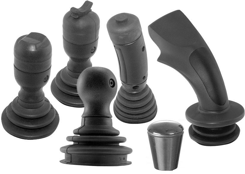
4 General Information Introduction Danfoss joysticks offer mobile machine product engineers a wide array of grip designs. Each of the grip designs outlined in this document meets the demanding conditions typically found in mobile equipment environments. The many available grip features provide OEM engineers with options offering a high degree of protection from chemicals, high-pressure wash, shock, vibration and EMC exposure. Danfoss grips are appropriate for both in-cabin and out of cabin applications and feature ergonomic forms that minimize machine operator fatigue. This publication provides technical information required to specify the grip portion of JS000 and JS6000 joysticks. Danfoss JS000 Joystick Base Technical Information, BC and JS6000 Joystick Base Technical Information, BC00000 provide technical information required to specify joystick bases. JS000, JS6000 grip selection guide Grip options and joystick base compatibility JS000, JS6000 grip options and joystick base compatibility Use the following table to determine which joystick base mates with specific Danfoss joystick grips. Grip designation Compatible with Grip functionality (maximum number) Operator Momentary es Proportional inputs JS000 base JS6000 base Rocker Banana Roller PRO X X (6) X () Grip with Rocker X X () Grip with Banana Ball X X () X A X X (8) X () X () MG X X () X () HKN X JS000, PRO grip Grip with rocker and grip with banana Ball grip A grip MG grip HKN grip Danfoss February 08 50L087 BC en-US080
5 General Information Product configuration model code A product configuration model code (model code) is used to specify particular features when ordering JS000 or JS6000 joysticks. The model code begins with the product family name and the remaining fields are filled in to configure the product with the desired features. JS000 and JS6000 model codes contain information relating to both base features and grip features. Danfoss February 08 50L087 BC en-US080 5
6 JS000 grips JS000 base model code JS000 grip product configuration model code example base part A, B, C, D and E A B C D E F G H J J S X Y A J T A Product family JS000 JS000 joystick base with DEUTSCH connector, spring return to center B Single or dual axis XY NY NG Dual axis function, forward and reverse with left and right, with guided axis (force is increased in the corners) Single axis function, forward and reverse Dual axis function, without guided axis feel (free moving in all directions) C Center return spring A B Standard spring Heavy spring D Electrical interface options J S CAN with J99 message protocol Analog voltage output D Joystick CAN source address NN None use with analog output (when D=S) Source address = (hex) Source address = (hex) 5 Source address = 5 (hex) 6 Source address = 6 (hex) D Joystick output type N None use with analog output (when D=S) CAN full scale output = 000 counts E Grip mounting options B Bottom mount (from below the panel, no boot retainer included, boot is captured between panel and housing) with vent plug * C Bottom mount (from below the panel, no boot retainer included, boot is captured between panel and housing) without vent plug * 6 Danfoss February 08 50L087 BC en-US080
7 JS000 grips E Grip mounting options (continued) T Top mount (from above the panel, includes boot retainer for attaching boot to joystick housing) with vent plug * U Top mount (from above the panel, includes boot retainer for attaching boot to joystick housing) without vent plug * * Vent plug is a Gore-Tex moisture barrier. If the plug is not present, Ingress Protection below the base is unrated. PRO grip option top mount only. JS000 grip model code JS000 grip product configuration model code example joystick part E and F A B C D E F G H J J S X Y A J T P R O R R R E Grip mounting and handle options PRO PR K0 LSW LSB PRO grip, CAN output. Complete section F, G, H, J PRO grip, with no or proportional functions, CAN output. Ball grip Do not complete F, G, H, J Grip with analog rocker,.5 to.75 V DC range. Do not complete F, G, H, J Grip with banana,.5 to.75 V DC range. Do not complete F, G, H, J PRO grip available with CAN option only. Grips with es available with analog option only. F PRO grip function layout R... L... Right handed grip Left handed grip F PRO grip function layout Number of es on the front plate.0.. No es es... es... es es F PRO grip function layout..r...n. Type of proportional function Roller or wheel, not sealed None Danfoss February 08 50L087 BC en-US080 7
8 JS000 grips F PRO grip function layout...n...r...l...b...d...s...t Position of proportional function No proportional function required Vertical proportional function on the Right-hand side Vertical proportional function on the Left-hand side Horizontal proportional function on the Bottom Vertical proportional functions on both the left and the right-hand sides Horizontal proportional functions as dual set on the top and the bottom Horizontal proportional function on top JS000 grip product configuration model code example joystick part E and F A B C D E F G H J J S X Y A J T P R O R R L R Y Y N R N G N F Grip function layout examples R0NN Right handed, 0 es, No roller, No position RRL Right handed, es, Roller, Left positioned RNN Right handed, es, No roller, No position RRL Right handed, es, Roller, Left positioned RNN Right handed, es, No roller, No position R0RB Right handed, 0 es, Roller, Bottom positioned RNN Right handed, es, No roller, No position RRB Right handed, es, Roller, Bottom positioned RNN Right handed, es, No roller, No position RRB Right handed, es, Roller, Bottom positioned R5NN Right handed, 5 es, No roller, No position RRT Right handed, es, Roller, Top positioned R0RR Right handed, 0 es, Roller, Right positioned R0RD Right handed, 0 es, Roller, Dual positioned RRR Right handed, es, Roller, Right positioned RRD Right handed, es, Roller, Dual positioned RRR Right handed, es, Roller, Right positioned R0RS Right handed, 0 es, Roller, Stacked positioned RRR Right handed, es, Roller, Right positioned RRS Right handed, es, Roller, Stacked positioned R0RL Right Handed, 0 es, Roller, Left positioned RNR Right handed, es, No roller, Right positioned RRL Right Handed, es, Roller, Left positioned RNL Right handed, es, No roller, Left positioned G PRO grip side orientation R. Right handed PRO Grip L. Left handed PRO Grip G PRO grip side color.r Red side.y Yellow side.b Black side.g Grey side.n No side 8 Danfoss February 08 50L087 BC en-US080
9 JS000 grips H PRO grip front plate color selection examples NNNNN No es (diagram 0NN * ) RYBGR Position Red, position Yellow, position Black, position Grey, position 5 Red (diagram 5NN * ) YYYYY 5 Yellow es (diagram 5NN * ) RNNRB Position Red, No position, No position, position Red, position 5 Black (diagram NN * ) YRNNN Position Yellow, Position Red, No position, No position, No position 5 (diagram RL * ) * See Front plate model code designations on page. Number refers to button location on grip front panel. Select one color code for each specified. J Operator Presence option not available N No: operator option not selected Danfoss February 08 50L087 BC en-US080 9

10 JS000 grips PRO grip PRO grip Overview The PRO grip is a patented ergonomic joystick grip that is designed to minimize operator fatigue in operations requiring repetitive, precision movement over extended periods of time. The grip is available in right and left hand versions. The profile of the PRO grip ensures that the operators fingers are close to input functions thus maximizing functional control. The hand rest at the base of the grip and soft feel elastomeric palm insert contributes to a comfortable feel and provides additional protection for the joystick boot. A unique feature of the grip is the intelligent embedded electronics that allows joystick input information to be multiplexed into a two-wire serial signal communicating with base electronics. The intelligent electronics facilitate the compact design of the grip by eliminating the need to pass large numbers of discrete wires through the joystick shaft. The PRO grip is available with a maximum of six inputs or two proportional inputs, or a mix of and proportional inputs. The PRO grip is not recommended in an open cab environment. Model code nomenclature Grip and grip options are specified using the Danfoss joystick model code. For grips designed to mate with the JS000 joystick base, use code positions E, F, G and J to specify grip properties. Reference JS000 base model code on page 6. The PRO grip uses all portions of the model code. Other JS000 grips use only the E portion of the model code. Specifications PRO grip es and proportional rollers are internally wired to a microcontroller located in grip. Grip information is included in joystick base CAN messages. Electrical action type mechanical life Specification Momentary Single pole, NO million cycles 0 Danfoss February 08 50L087 BC en-US080
11 JS000 grips Environmental Specification Operating temperature -0 C to 75 C [- F to 67 F] Storage temperature -0 C to 85 C [-0 F to 85 F] Environmental sealing (without proportional roller) IP Proportional Roller Specifications Specification Roller action Spring return to center Roller electrical output ±000 counts from null Roller mechanical life 5 million cycles Environmental sealing IP 0 Proportional rollers are not to be used in no cabin or open cabin joystick applications. Connector pin assignments PRO grips mounted on JS000 joystick bases that have user inputs es, proportional inputs or a mix of both must use the CAN electrical output option to transmit grip and proportional function information. Refer to the JS000 Joystick Base Technical Information, BC for grip CAN message details and connector pin assignments. Danfoss February 08 50L087 BC en-US080
12 JS000 grips PRO grip front plate diagram Front plate model code designations NN 0RR 0RL 0RB 0RD P P P P P P P 0RS NN RR RL RB P P 5 P RD P P 5 NN RR RL RB P P P NR NL NN 5 RR RL P P P RT NN P RRB - RY 9 5 5NN 5 F F F G G F kwa Number of es. 0 Proportional function in grip (prop). Right prop. Left prop 5. Bottom/top prop 6. Dual prop 7. Stacked prop 8. Front plate configuration example 9. Position 6 Pushbutton colors R Y B G N Red Yellow Black Grey None Danfoss February 08 50L087 BC en-US080
13 Technical Information JS000 grips Dimensions Pro grip dimensions in millimeters [inches]. 8o REF 8o REF 5 7. ± 0.5 DIA [. ± 0.0] 9. ± ± ± 0.5 [0.5 ± 0.0] Ø59. ± 0.5 [. ± 0.0] 7 [0.7 ± 0.0] [.9 ± 0.0] 66.0 ± 8o REF [6.55 ± 0.0] 8o REF x Ø.57 ± 0.05 [0.80 ±0.00] 6 R.0 ± ± 0. 5 [.5 ± 0.005] 57.5 ± 0. [.5 ± 0.005] [.8 ± 0.0] ± 0.5 [.75 ± 0.0].9 ± 0.5 [0.08 ± 0.0] 8.58 ± 0. [.5 ± 0.005] 57.5 ± 0. [.5 ± 0.005].9 ± 0.5 [.8 ± 0.0] ± 0.5 [.75 ± 0.0] kwa Pin Decreasing X Increasing X Decreasing Y Increasing Y Pin 6 Orientation feature Danfoss February 08 50L087 BC en-US080

14 JS000 grips Grip with rocker and grip with banana Grip with rocker and grip with banana Overview JS000 grips with es are intended to provide a simple, flexible and comfortable operator control that includes a proportional input device at the top of the grip. Two shapes are available for the proportional input device: V rocker or banana rocker. Both grips use Hall sensing technology to detect rocker position. The proportional input generates a nominal 0 to 5 Vdc signal that is used as a change of state () input. Model code nomenclature Grip and grip options are specified using the Danfoss joystick model code. For grips designed to mate with the JS000 joystick base, use code positions E, F, G and J to specify grip properties. Reference JS000 base model code on page 6 The grip with rocker and grip with banana are designated using only the E portion of the code. Specifications Top electrical Supply voltage Maximum survival voltage Maximum current draw Output at maximum displacement Output at null Output at minimum displacement Specification 5.0 ± 0.5 Vdc 8 Vdc Continuous 0 ma 75% ± 8% of supply voltage 50% ± % of supply voltage % ± 8% of supply voltage Top environmental Operating temperature Storage temperature EMI/RFI rating Mechanical life Specification -0 C to 80 C [-0 F to 75 F] -0 C to 85 C [-0 F to 80 F] 00 V/m 6 million cycles Danfoss February 08 50L087 BC en-US080
15 JS000 grips Connector pin assignments Both grip-with- options may use either the JS000 base analog or CAN output option. Refer to the JS000 Joystick Base Technical Information, BC for grip CAN message details and connector pin assignments. Grip with rocker dimensions Grip with rocker dimensions in millimeters [inches] ± 0.50 [.75 ± 0.0] X Ø.57 ± 0.05 [0.80 ± 0.00] R.0 ± 0.50 [0.08 ± 0.0] ± 0.50 [.75 ± 0.0] 8 REF 8 REF 8 REF 8 REF 0.6 ± 0.50 [.5 ± 0.0] 5.80 [0.5] ± 0.50 [.5 ± 0.0] 6.5 ± 0.50 [.5 ±.0] Ø 59. ± 0.50 [. ± 0.0]. Decreasing X. Increasing X. Decreasing Y. Increasing Y 5. Maximum panel feed-through mounting 6. Orientation feature kwa Danfoss February 08 50L087 BC en-US080 5
16 JS000 grips Grip with banana dimensions Grip with banana dimensions in millimeters [inches]. 5 X Ø.57 ± 0.05 [.80 ±.00] ± 0.50 [.75 ± 0.0] R.0 ± 0.50 [0.08 ± 0.0] ± 0.50 [.75 ± 0.0] 8 REF 8 REF REF 8 REF 5. ± 0.50 [.5 ± 0.0] 7.80 [0.5] ± 0.50 [.5 ±.0] 6.5 ± 0.50 [.5 ± 0.0] Ø 59. ± 0.50 [. ± 0.0]. Decreasing X. Increasing X. Decreasing Y. Increasing Y 5. Decreasing 6. Increasing 7. Maximum panel feed-through mounting 8. Orientation feature kwa Danfoss February 08 50L087 BC en-US080
17 JS000 grips Ball grip Ball grip Overview The JS000 Ball grip provides a simple and comfortable operator control. Manufactured of high impact plastic, the grip is perfectly suited for mobile machine applications requiring only X-Y control and no or proportional input options. Model code nomenclature Grip and grip options are specified using the Danfoss joystick model code. For grips designed to mate with the JS000 joystick base, use code positions E, F, G and J to specify grip properties. Reference JS000 base model code on page 6. The ball grip is designated using only the E portion of the code. Specifications Environmental Specification Operating temperature -0 C to 80 C [-0 F to 75 F] Storage temperature -0 C to 85 C [-0 F to 80 F] Environmental protection IP 66, 67 Connector pin assignments The ball grip has no electrical outputs. It can be mounted on JS000 bases having either a CAN or analog output. Refer to the JS000 Joystick Base Technical Information, BC for grip CAN message details and connector pin assignments. Danfoss February 08 50L087 BC en-US080 7
18 JS000 grips Dimensions Ball grip dimensions in millimeters [inches] ± 0.50 [.75 ± 0.0] x Ø.57 ± 0.05 [0.80 ± 0.00] R.0 ± 0.5 [0.08 ± 0.0] ± 0.5 [.75 ± 0.0] 8 o REF 8 o REF 8 o REF 8 o REF 86.6 ± 0.5 [. ± 0.0].8 [0.5] ± 0.5 [.5 ± 0.0] 6.5 ± 0.5 [0.5 ± 0.0] Ø59. ± 0.05 [. ± 0.00]. Decreasing X. Increasing X. Decreasing Y. Increasing Y 5. Maximum panel feed-through mounting 6. Orientation feature kwa Danfoss February 08 50L087 BC en-US080
19 JS6000 base model code JS6000 product configuration model code example base part A, B, C, D, E, F and G A B C D E F G H I J K L M N O P Q R S J S X Y H M M H S N L N J A 0 H 0 R V N N N N N N N N A Product series JS6000 Series JS6000 joystick B Operational axis options XY NY Bi-directional: X and Y axis Uni-directional: Y axis only (required for friction-holding) C Shaft position sensing and output options PRR PQQ PSS PTT PUU HMM CAN CPL Potentiometer: single output per axis; Vo = 0 to 90% of Vs; ±.5 neutral threshold Potentiometer: single output per axis; Vo = 5 to 75% of Vs; ±.5 neutral threshold Potentiometer: single output per axis; Vo = 0 to 90% of Vs; ±5 neutral threshold Potentiometer: single output per axis; Vo = 5 to 75% of Vs; ±5 neutral threshold Potentiometer: dual output per axis; Vo = 0 to 90% of Vs; ±.5 neutral threshold Hall effect: dual sensors per axis; Vs = 5 VDC; Vo = 0.5 to.5 VDC Hall effect: dual sensors per axis; Vs = 9 to 6 VDC; CAN.0B communication, 6 pin connector Hall effect: dual sensors per axis; Vs = 9 to 6 VDC; CAN.0B communication, 8 pin connector D Centering spring options H M L F Heavy force Medium force Light force Friction-hold (position maintained, center detent) E Gate pattern options S Square, full output at 5 degree F Mechanical options NL FB No mechanical option; spring return to center only Friction-held in Y axis; no X axis; center detent;.5 Nm [0.9 lb ft] friction-hold force;.5 Nm [.66 lb ft] breakout force Danfoss February 08 50L087 BC en-US080 9
20 F Mechanical options (continued) FC HC Friction-held in Y axis; no X axis; center detent;.5 Nm [0.9 lb ft] friction-hold force;.5 Nm [.0 lb ft] breakout force Friction-held in Y axis; no X axis; center detent;.5 Nm [.66 lb ft] friction-hold force;.0 Nm [.95 lb ft] breakout force G Direction (micro) options N Y No es Microes installed (analog potentiometer option only) model code JS6000 grip product configuration model code example grip properties - I, J, K, L, M, N, O, P, Q, R, and S A B C D E F G H I J K L M N O P Q R S J S X Y H M M H S N L N J A 0 H 0 R V N N N N N N N N H Electrical interface options S J Analog (voltage output from joystick sensors or es) CAN, SAE J99 protocol H, CAN Source Address* NN None use with analog outputs when H = S Source address = 0x Source address = 0x 5 Source address = 0x 5 6 Source address = 0x 6 * Consult the factory if additional source addresses are required. H Joystick output type N None use with analog outputs when H = S CAN full scale output = 000 counts I, J, K Grip proportional rocker output and style For grips designed to mate with the JS6000 joystick base, use code positions, I through S to specify grip properties. Refer to Front plate model code designations on page 5 for rocker location examples. 0 Danfoss February 08 50L087 BC en-US080
21 I Grip details I Handle type Number of buttons L Left rocker location (vertical orientation) R Right rocker location (vertical orientation) B Both left and right (vertical orientation) H Horizontal rocker location 0 No rocker T Top D Operator Presence B Both top and Operator Presence 0 No top, no Operator Presence J A grip proportional rocker output R Q N Potentiometer, 0% to 90% Vs Potentiometer, 5% to 75% Vs None K A grip proportional rocker style S V N Wave style V style None L, M, N, O, P, Q, R, S Grip options For A grips use code positions L, M, N, O, P, Q, R, and S to specify grip button colors. Grip button position to model code conversion Grip front plate button position Corresponding master model code L M N O 5 P 6 Q 7 R 8 S See A grip connector pin assignments on page 0. Grip Button Color Options R Red B Black Danfoss February 08 50L087 BC en-US080
22 Grip Button Color Options (continued) G Green Y Yellow L Blue N No pushbutton The red colored pushbutton is considered the default color. There is a five-piece order minimum each time the other color options are ordered. JS6000 connector pin assignments JS6000 grip function connector pin assignments for the JS6000 connector that contains grip outputs are dependent on the type of joystick shaft position sensor (potentiometer or Hall) and the electrical output option (analog or CAN) selected for the joystick base. Analog base grip pin assignments are found in A grip connector pin assignments on page 0 and MG grip connector pin assignments on page 6 of this manual. Pin assignments for other analog base functions are found in the JS6000 Joystick Base Technical Information, BC Grip pin assignments for joystick bases that have analog outputs depend on whether a potentiometer or Hall sensor is used to measure the position of the joystick shaft. If a potentiometer is used, the pin connector on the joystick base is used for grip outputs. If a Hall sensor is used, the 6 pin connector is used for grip outputs. If the CAN electrical output option is selected, a 6 or 8 pin DEUTSCH connector is provided in the base and input information from the grip is broadcast in a J99 message format. Refer to the JS6000 Joystick Base Technical Information, BC00000 for details on J99 CAN grip messages and DEUTSCH connector pin assignments. Danfoss February 08 50L087 BC en-US080
23 A grip A grip Multi-function grip. Pushbutton. Top. Operator Presence. Left rocker kwa Overview Model code for a grip front plate options I Number of momentary es grip front plate The A grip is a multi-function, ambidextrous ergonomic grip designed for a comfortable user interface and maximum functional control. The grip features a modular design that allows and proportional rocker location flexibility. The A grip is available with combinations of up to eight es and up to two proportional inputs. One of the optional es can be used to provide an Operator Presence function on the grip. Available button colors are red, black, green, yellow, and blue. Model code nomenclature Grip and grip options are specified using the Danfoss joystick model code. For grips designed to mate with the JS6000 joystick base, use code positions I through S to specify grip properties. Reference JS6000 grips model code on page 0. Number, location of proportional rocker es grip front plate A A00T 0 0 T A00D 0 0 D A00B 0 0 B A0L0 0 L 0 A0LD 0 L D A0R0 0 R 0 A0RD 0 R D A0B0 0 B 0 Number, location of momentary es back of grip Danfoss February 08 50L087 BC en-US080
24 Model code for a grip front plate options (continued) I Number of momentary es grip front plate Number, location of proportional rocker es grip front plate A0BD 0 B D A0H0 0 H 0 A0HD 0 H D A0RB 0 R B A0RT 0 R T A0LB 0 L B A0LT 0 L T A A0T 0 T A0D 0 D A0B 0 B AL0 L 0 AR0 R 0 AH0 H 0 ALD L D ARD R D AHD H D ART R T ALT L T ARB R B ALB L B A A0T 0 T A0D 0 D A0B 0 B AL0 L 0 AR0 R 0 AH0 H 0 ALD L D ARD R D AHD H D ARB R B ART R T ALB L B ALT L T A A0T 0 T A0D 0 D A0B 0 B AR0 R 0 ARD R D Number, location of momentary es back of grip Danfoss February 08 50L087 BC en-US080
25 Model code for a grip front plate options (continued) I Number of momentary es grip front plate Number, location of proportional rocker es grip front plate AL0 L 0 ALD L D ART R T ALT L T A A0T 0 T A0D 0 D A0B 0 B A A50D 5 0 D A50B 5 0 B A50T 5 0 T A A60D 6 0 D A60B 6 0 B A60T 6 0 T Number, location of momentary es back of grip Front plate model code designations A grip front plate diagram A000 A00T A00D A00B A0B0 X Y AR0 ART ARD ARB Y A00 A0T A0D A0B AH0 AHD X A0R0 A0RT A0RD A0RB Y A0H0 A0HD X AL0 ALT ALD ALB X AR0 ART ARD ARB Y A00 A0T A0D A0B A0L0 A0LT A0LD A0LB X A00 A0T A0D A0B AH0 AHD X AL0 ALT ALD ALB X A00 A0T A0D A0B AR0 ART ARD ARB 5 Y AL0 ALT ALD ALB X 6 A500 A50T A50D A50B 5 A600 A60T A60D A60B 5 6 kwa Danfoss February 08 50L087 BC en-US080 5
26 Rocker profiles Profile of wave rocker option kwa Profile of V rocker option kwa Rocker specifications The optional grip rocker es use a conductive plastic potentiometer to generate an analog output that is proportional to position. The wipers that run across the potentiometer track are driven by the thumb operated rocker mechanism. Rocker action is spring return to center. Mechanical Breakout force Operating force Maximum applied force Mechanical angle of movement ± Electrical angle of movement ± 9 Expected life Specification 5 N [. lbf] 5 N [.7 lbf] 50 N [. lbf] >5 million operations Environmental Specification Operating temperature -0 C to 70 C [-0 F to 58 F] Storage temperature -0 C to 80 C [-0 F to 76 F] Environmental sealing IP 65 6 Danfoss February 08 50L087 BC en-US080
27 Electrical Specification Maximum load current Potentiometer wiper * Directional es: 00 ma Maximum power dissipation 0.5 W at 5 C [77 F] Output voltage ranges 5 to 75% Vs 0 to 90% Vs Center tap voltage 50% Vs ± % Center tap angle Directional operating angle Directional maximum supply voltage Directional current rating.5 either side of center.5 either side of center 6 Vdc * The rocker is only to be used as a potentiometer and not as a variable resistor. Wiper load must be resistance greater than 00 kω. Center tap has an angle of ±.5 50% of the Vs is supplied at the center position The track also has a directional with a center off The direction changes state after a movement of.5 in each direction The current rating is 5 ma 5 ma Rocker wiring details Left rocker kwa Black. Blue/orange. track. Green 5. Left blank 6. Center tap (yellow/red) 7. Forwards 8. 0 V 9. Potentiometer track 0. 5 V. Backwards. White/red (V+). Pink. Pink/gray (V-) Danfoss February 08 50L087 BC en-US080 7
28 Right rocker kwa Black. Blue. track. Yellow 5. Left blank 6. Center tap (yellow/red) 7. Backwards 8. 5 V 9. Potentiometer track 0. 0 V. Forwards. Pink/gray (V+). White. White/red (V-) Horizontal rocker kwa Black. Blue. track. Green 5. Left blank 6. Center tap (yellow/red) 7. Left 8. 0 V 9. Potentiometer track 0. 5 V. Right. White/red (V+). Pink. Pink/gray (V-) Pushbutton specifications Electrical action type Contact rating Contact resistance Mechanical life Specification Momentary Single pole, NO 00 ma at 50 Vdc - person present 00 ma at 50 Vdc - top and front plate es 50 MΩ maximum million cycles 8 Danfoss February 08 50L087 BC en-US080
29 Environmental Specification Operating temperature -0 F to 70 C [-0 C to 58 F] Storage temperature -0 F to 80 C [-0 C to 76 F] Environmental sealing IP 66 Operating force N [0.67 lbf] Pushbutton wiring details Pushbutton es kwa Blue. Yellow. Yellow/Orange. Green 5. 5 Red 6. 6 Violet 7. Black Top. Pink with marker sleve. Black Operator Presence kwa kwa Danfoss February 08 50L087 BC en-US080 9
30 . Red/Green. Black/White A grip connector pin assignments W Warning Potential uncommanded machine movement. JS6000 base and grip pinout specifications are a function of joystick base measurement sensor type and electrical output (analog or CAN). For joysticks with analog output, the pinout assignments for the and 6 pin connectors depend on whether a potentiometer or Hall sensor is used to measure the position of the joystick shaft. If a potentiometer sensor is used, the pin connector is used for grip outputs. If a Hall sensor is used, the 6 pin connector is used for grip outputs and pins through 6 are not used. Refer to the Rocker specifications on page 6 for information regarding the nomenclature used below. Refer to Front plate model code designations on page 5 for information regarding the location nomenclature for push button es. Pins to 6 are not used on the 6 pin connector Blank = Pin not used A grip button position designations Pin number A000 A00T A00D A00B A0L0 A0LD A0LT A0LB A0R0 A0RD A0B0 A0BD A0H0 A0HD A0RT out H out H out H out H Top Top Operator Operator Common Common Common VoutL Center tap V+ V- Common VoutL Center tap V+ Operator VoutL Center tap V+ Top VoutL Center tap V+ Operator Top Operator Operator V- Common Operator V- Common V- Common Operator Center tap V+ VoutR V- Common Center tap V+ Operator VoutR V- Common Operator VoutL Center tap V+ VoutR V- Common VoutL Center tap V+ Operator VoutR V- Common Operator VoutH Center Tap V+ V- Common VoutH Centertap V+ Operator Top V- Common Operator Center tap V+ VoutR V- Common A00 PB Common 0 Danfoss February 08 50L087 BC en-US080
31 A grip button position designations (continued) Pin number A0T PB Top A0D PB Operator A0B PB Top AL0 AR0 PB AH0 ALD out H PB ARD PB AHD out H PB ART PB ALT ARB PB ALB Operator Common Common Common PB VoutL Center tap V+ V- Common out H Center tap V+ VoutR V- Common VoutH Center top V+ V- Common PB VoutL Center tap V+ Operator out H Center tap V+ Operator VoutH Center top V+ Operator Top Operator Operator V- Common Operator VoutR V- Common Operator V- Common Operator Center tap V+ VoutR V- Common PB VoutL Center tap V+ Top Top Center tap V+ Operator PB VoutL Center tap V+ Operator V- Common VoutR V- Common Operator Top V- Common Operator A00 PB PB Common A0T PB PB Top A0D PB PB Operator A0B PB PB Top AL0 AR0 PB PB AH0 ALD out H Operator Common Common Common PB PB VoutL Center tap V+ V- Common PB PB out H ARD PB PB AHD out H Center tap V+ VoutR V- Common VoutH Center tap V+ V- Common PB PB VoutL Center tap V+ Operator PB PB out H ARB PB PB Center tap V+ Operator VoutH Center tap V+ Operator Top Center tap V+ Operator Operator Operator V- Common Operator VoutR V- Common Operator V- Common Operator VoutR V- Common Operator Danfoss February 08 50L087 BC en-US080
32 A grip button position designations (continued) Pin number ART PB PB ALB ALT Top Center tap V+ VoutR V- Common PB PB VoutL Center tap V+ Operator Top PB PB VoutL Center tap V+ Top V- Common Operator V- Common A00 PB PB PB Common A0T PB PB PB Top A0D PB PB PB Operator A0B PB PB PB Top AR0 PB PB ARD PB PB AL0 ALD ART PB PB ALT Operator Common Common Common Center tap V+ PB5 VoutR V- Common PB5 Center tap V+ Operator Operator Operator VoutR V- Common Operator PB PB VoutL Center tap V+ PB6 V- Common PB PB VoutL Center tap V+ Operator Top PB6 V- Common Operator Center tap V+ PB5 VoutR V- Common PB PB VoutL Center tap V+ PB6 Top V- Common A00 PB PB PB PB Common A0T PB PB PB PB Top A0D PB PB PB PB Operator A0B PB PB PB PB Top Operator Common Common Common A500 PB PB PB PB PB5 Common A50D PB PB PB PB PB5 Operator A50B PB PB PB PB Top A50T PB PB PB PB Top Operator PB5 Common Operator Operator Operator PB5 Common Operator Common A600 PB PB PB PB PB5 PB6 Common A60D PB PB PB PB PB5 Operator A60B PB PB PB PB Top A60T PB PB PB PB Top PB5 Operator PB6 Common Operator PB6 Common Operator PB5 PB6 Common Danfoss February 08 50L087 BC en-US080
33 Dimensions A grip dimensions in millimeters [inches]. 60 [.6].5 [5.8] 0 [.]. Pushbutton. Top. Operator Presence. Left rocker kwa98595 Danfoss February 08 50L087 BC en-US080

34 MG grip MG grip Overview The MG multi-function grip is designed to provide an ergonomic solution to grip applications requiring an operator function. The profile of the MG grip ensures that the operators fingers are always close to the buttons to minimize operator fatigue and maximize functional control. An optional hand rest feature is also available to further minimize operator fatigue and provide additional protection for the joystick boot. The grip is available with or without an operator lever, as well as up to two low current es at the top of the grip. If two top es are present, they are actuated through a rocker assembly. 0 option with Operator Presence lever. Operator lever option with Operator Presence lever kwa position. Operator lever kwa Danfoss February 08 50L087 BC en-US080


35 option with Operator Presence lever. position. position. Operator lever Grip with hand rest option kwa56709 Model code nomenclature Grip and grip options are specified using the Danfoss joystick model code. For grips designed to mate with the JS6000 joystick base, use code positions I, J and K to specify grip properties. Reference JS6000 base model code on page 9. MG grip model codes do not use model code positions J through S. Model code for MG grip positions position * Operator lever Hand rest MG00 No es No lever No hand rest MG0 No lever No hand rest MG0, No lever No hand rest MG0, Included No hand rest MG0, Included Included MG05 Included Included MG06, No lever Included MG07 No lever Included Danfoss February 08 50L087 BC en-US080 5
36 Model code for MG grip positions (continued) position * Operator lever Hand rest MG08 Included No hand rest MG09 No es Included Included MG0 No es No lever Included MG No es Included No hand rest * Refer to Dimensions on page 9, for definition of locations. Specifications Electrical Contact resistance Contact bounce Insulation resistance Dielectric strength ing current ing voltage Electrical life Specification 50Ω ms >00 MΩ at 50 Vdc 500 V (50 Hz, min.) Max: 00 ma Min : 0 µa Max: 0 Vdc Min: Vdc million cycles at maximum voltage Environmental Operating temperature Storage temperature Ingress protection Specification -5 C to 75 C [- F to 67 F] -0 C to 80 C [- F to 78 F] IP 67 (operator lever may not operate in icing conditions) MG grip connector pin assignments W Warning Potential uncommanded machine movement. JS6000 base and grip connector pin assignments are a function of joystick base shaft measurement sensor type and base electrical output (analog or CAN). For joysticks with analog output, the pin assignments for the and 6 pin base connectors depend on whether a potentiometer or Hall sensor is used to measure the position of the joystick shaft. If a potentiometer sensor is used, the pin connector is used for grip outputs. If a Hall sensor is used, the 6 pin connector is used for grip outputs. pin connector MG grip pin assignments Pin number Not used Not used Operator 5 Operator 6 Danfoss February 08 50L087 BC en-US080
37 pin connector MG grip pin assignments (continued) Pin number 6 7 Not used 8 Not used 9 Not used 0 Not used Not used Common for, 6 pin connector MG pin assignments Pin number Not used Not used Operator 5 Operator 6 7 Not used 8 Not used 9 Not used 0 Not used Not used Common for, Not used Not used 5 Not used 6 Not used wiring details option.. Blue. Black kwa Danfoss February 08 50L087 BC en-US080 7
38 option 5 kwa Blue. Black 5. Green Operator Presence kwa Operator Presence. Yellow. Blue/orange 8 Danfoss February 08 50L087 BC en-US080
39 Dimensions MG grip dimensions in millimeters [inches]. ø0 [ø.57] 5 [. ] 8 [. ] [ 0.55 ] 88 [ 7. ] [.5 ] ø50 [ø.97] kwa98557 Danfoss February 08 50L087 BC en-US080 9

40 HKN grip HKN grip Overview The HKN grip is a plain, high impact plastic knob grip that has no electrical interface. It is designed to provide a comfortable grip for extended machine operation. Model code Grip and grip options are specified using the Danfoss joystick model code. For grips designed to mate with the JS6000 joystick base, use code positions I, through S to specify grip properties. Reference JS6000 base model code on page 9 and model code on page 0. The HKN does not use master model code positions J through S. The master model code for HKN grips is HKN0. Environmental specifications Environmental Specification Operating temperature -0 C to 80 C (-0 F to 76 F) Storage temperature -0 C to 85 C (-0 F to 85 F) Environmental sealing IP 66 Dimensions HKN grip dimensions Maximum height above flange Maximum diameter 5 mm [.76 in].6 mm [.6 in] 0 Danfoss February 08 50L087 BC en-US080
41 Service parts JS000 service part availability Service part availability for JS000 joystick is a function of joystick base and grip specifications. Refer to the JS000 Base Technical Information, BC for mating connector part information. Refer to the table below for service part information. JS000 joystick grip and base service parts Grip type Part description Replacement part ordering number JS000 ball grip Boot 055 JS000 grip with, rocker and banana JS000 PRO grip Ball grip 009 Grip fastening screw 0078 Rocker cover 007 Banana cover 0086 No replacement parts available Danfoss February 08 50L087 BC en-US080
42 Danfoss February 08 50L087 BC en-US080
43 Danfoss February 08 50L087 BC en-US080
44 Products we offer: Bent Axis Motors Closed Circuit Axial Piston Pumps and Motors Displays Electrohydraulic Power Steering Electrohydraulics Danfoss Power Solutions is a global manufacturer and supplier of high-quality hydraulic and electronic components. We specialize in providing state-of-the-art technology and solutions that excel in the harsh operating conditions of the mobile off-highway market. Building on our extensive applications expertise, we work closely with our customers to ensure exceptional performance for a broad range of off-highway vehicles. We help OEMs around the world speed up system development, reduce costs and bring vehicles to market faster. Danfoss Your Strongest Partner in Mobile Hydraulics. Hydraulic Power Steering Go to for further product information. Integrated Systems Wherever off-highway vehicles are at work, so is Danfoss. We offer expert worldwide support for our customers, ensuring the best possible solutions for outstanding performance. And with an extensive network of Global Service Partners, we also provide comprehensive global service for all of our components. Joysticks and Control Handles Microcontrollers and Software Open Circuit Axial Piston Pumps Orbital Motors Please contact the Danfoss Power Solution representative nearest you. PLUS+ GUIDE Proportional Valves Sensors Steering Transit Mixer Drives Comatrol Local address: Turolla Hydro-Gear Daikin-Sauer-Danfoss Danfoss Power Solutions (US) Company 800 East th Street Ames, IA 5000, USA Phone: Danfoss Power Solutions GmbH & Co. OHG Krokamp 5 D-59 Neumünster, Germany Phone: Danfoss Power Solutions ApS Nordborgvej 8 DK-60 Nordborg, Denmark Phone: Danfoss Power Solutions Trading (Shanghai) Co., Ltd. Building #, No. 000 Jin Hai Rd Jin Qiao, Pudong New District Shanghai, China 006 Phone: Danfoss can accept no responsibility for possible errors in catalogues, brochures and other printed material. Danfoss reserves the right to alter its products without notice. This also applies to products already on order provided that such alterations can be made without changes being necessary in specifications already agreed. All trademarks in this material are property of the respective companies. Danfoss and the Danfoss logotype are trademarks of Danfoss A/S. All rights reserved. Danfoss February 08 50L087 BC en-US080
JS1000, JS6000 Joystick Grips. Technical Information
 JS1000, JS6000 Joystick Grips Technical Information Revisions Revisions Revisions Date Page Changed Rev. 15 Jan, 2010 25 A Grip Front Plate Diagram illustration GA 17 Dec, 2009 10-11 Pro grip recommendation,
Joystick JS6000 Analog Output
 Electrical Installation Joystick powersolutions.danfoss.com Revision history Table of revisions Date Changed Rev May 2017 Updated to Engineering Tomorrow design 0201 August 2015 Converted to Danfoss layout
Joysticks JS1 Heavy Duty
 Electrical Installation Joysticks JS Heavy Duty powersolutions.danfoss.com Revision history Table of revisions Date Changed Rev December 20 Added PVE information 020 February 20 First edition 00 2 Danfoss
Joysticks JS1 Heavy Duty
 Electrical Installation Joysticks JS Heavy Duty powersolutions.danfoss.com Revision history Table of revisions Date Changed Rev January 208 Removed description for One 2 pin DEUTSCH connector topic and
JS1000 Joystick Analog Output Product Electrical Installation
 MAKING MODERN LIVING POSSIBLE Technical Information JS1000 Joystick Analog Output Product Electrical Installation powersolutions.danfoss.com Revision history Table of revisions Date Changed Rev July 2014
Joystick JS7000 Analog and CAN Output
 Electrical Installation Joystick powersolutions.danfoss.com Revision history Table of revisions Date Changed Rev May 2017 Updated to Engineering Tomorrow design 0201 July 2014 Converted to Danfoss layout
Temperature Sensors ,
 MAKING MODERN LIVING POSSIBLE Electrical Installation Temperature Sensors 1090173, 1090174 powersolutions.danfoss.com Revision history Table of revisions Date Changed Rev September 2015 Minor layout revision
Sensors Heavy-Duty Pressure Transmitter
 MAKING MODERN LIVING POSSIBLE Electrical Installation Sensors Heavy-Duty Pressure Transmitter powersolutions.danfoss.com Revision history Table of revisions Date Changed Rev August 2015 Converted to Danfoss
PLUS+1 Compliant JS1 J1939 CAN Joystick Function Block
 User Manual PLUS+1 Compliant JS1 J1939 CAN Joystick Function Block powersolutions.danfoss.com Revision history Table of revisions Date Changed Rev March 2018 Re-branding 0102 September 2015 0101 2 Danfoss
RS485 String Potentiometer (Yo-Yo) Sensor. Technical Information
 Sensor. Technical Information") RS485 String Potentiometer (Yo-Yo) Sensor Technical Information L1223774 Rev BA Jul 2013 Revisions Revision History Table of Revisions Date Page Changed Rev 24 Jul 2013 4, 5, 6 Feature and Options list,
RS485 String Potentiometer (Yo-Yo) Sensor Technical Information L1223774 Rev BA Jul 2013 Revisions Revision History Table of Revisions Date Page Changed Rev 24 Jul 2013 4, 5, 6 Feature and Options list,
PLUS+1 Compliant JS1 CANopen Joystick Function Block
 User Manual PLUS+1 Compliant JS1 CANopen Joystick Function Block powersolutions.danfoss.com Revision history Table of revisions Date Changed Rev March 2018 Re-branding 0102 January 2016 First edition 0101
Data Sheet. JS6000 Joystick Base
 Data Sheet JS6000 Joystick Base Mobile Machine Management The JS6000 joystick base is an element of the flexible, powerful, expandable, and affordable joystick family of mobile machine management products.
JS7000 Joystick Analog, CAN, and CAN+ Output. Product Electrical Installation. Technical Information
 JS7000 Joystick Analog, CAN, and CAN+ Output Product Electrical Installation Technical Information L1105361 Rev BA May 2012 Revisions Revision History Table of Revisions Date Page Changed Rev 18 May 2012
MAKING MODERN LIVING POSSIBLE. Technical Information. JS1000 Joystick Base. powersolutions.danfoss.com
 MAKING MODERN LIVING POSSIBLE Technical Information JS1000 Joystick Base powersolutions.danfoss.com Revision History Table of Revisions Date Changed Rev Mar 2014 SAE J1939 Extended Joystick message transmission
PLUS+1 Compliant CLS1000 Laser Sensor Function Block
 MAKING MODERN LIVING POSSIBLE User Manual PLUS+1 Compliant CLS1000 Laser Sensor Function Block www.powersolutions.danfoss.com About this Manual Organization and Headings To help you quickly find information
User Manual PLUS+1 Compliant ACX104 Function Block
 MAKING MODERN LIVING POSSIBLE User Manual PLUS+1 Compliant www.powersolutions.danfoss.com Revision History Revision Date Comment Rev CA July 2015 2015 Danfoss Power Solutions (US) Company. All rights reserved.
PLUS+1 Compliant MP1 NFPE Function Blocks
 User Manual PLUS+1 Compliant MP1 NFPE Function Blocks powersolutions.danfoss.com Revision history Table of revisions Date Changed Rev March 2018 Changed hex values for Hardware and General in the fault
JS120 Single Axis Fingertip Joystick. Technical Information
 JS120 Single Axis Fingertip Joystick Technical Information Revisions Version Revisions Date Page Change Rev. 13 Feb, 2007 Lever length options; connector pin assignments Rev-CA 12 May, 2006 7 Model code
JS120 Single Axis Fingertip Joystick. Technical Information
 JS120 Single Axis Fingertip Joystick Technical Information Revisions Version Revisions Date Page Change Rev. 2 July, 2009 8, 11 Corrected connector pin assignments and added output voltage curve DA 13
PLUS+1 GUIDE Software. AGCO Ag-Chem Fan Drive Subsystem Fault Location and Fault Type Codes User Manual. BlinkCodeGen. OutputDrivers. Faults.
 PLUS+1 GUIDE Software AGCO Ag-Chem Fan Drive Subsystem Fault Location and Fault Type Codes User Manual OutputDrivers Status Outputs Left Right Phase Drive Faults Status Inputs Cmd 158.2 mm 6.23 144.5 mm
2x 25.2 mm [1.0] 2x 7.0 [.28] MOUNTING DIRECTION #2 LED INDICATOR LIGHTS mm [2.03] 47.1 mm [1.85]
![2x 25.2 mm [1.0] 2x 7.0 [.28] MOUNTING DIRECTION #2 LED INDICATOR LIGHTS mm [2.03] 47.1 mm [1.85]](/thumbs/96/128482272.jpg "2x 25.2 mm [1.0] 2x 7.0 [.28] MOUNTING DIRECTION #2 LED INDICATOR LIGHTS mm [2.03] 47.1 mm [1.85]") PLUS+1 GUIDE Software PLUS+1 Compliant S4 PVEO Function Block 158.2 mm 6.23 144.5 mm 5.69 142.0 mm [5.59] 2x 25.2 mm [1.0] 97.0 mm [3.82] TM 2x 7.0 [.28] MOUNTING DIRECTION #2 COMPLI ANT PIN #1 INDICATED
PLUS+1 GUIDE Software PLUS+1 Compliant S4 PVEO Function Block 158.2 mm 6.23 144.5 mm 5.69 142.0 mm [5.59] 2x 25.2 mm [1.0] 97.0 mm [3.82] TM 2x 7.0 [.28] MOUNTING DIRECTION #2 COMPLI ANT PIN #1 INDICATED
System Description. System Hitch Control. powersolutions.danfoss.com
 System Description System powersolutions.danfoss.com Revision history Table of revisions Date Changed Rev July 2017 Updated recommended suppliers summary 0202 August 2015 Converted to Danfoss layout BA
Joysticks JS6000 Joystick Base
 Technical Information Joysticks powersolutions.danfoss.com Revision history Table of revisions Date Changed Rev April 2017 Updated to Engineering Tomorrow design 1104 April 2017 Minor correction to note
JS6000 Joystick Base. Technical Information
 JS6000 Joystick Base Technical Information Revisions Version Revisions Date Page Changed Rev. 04 Jan, 2008 26 A grip front plate diagram updated HA 14 Nov, 2007 3, 6, 7, 13, 17 Grip options model code
User Manual PLUS+1 License Administration Tool powersolutions.danfoss.com
 MAKING MODERN LIVING POSSIBLE User Manual PLUS+1 License Administration Tool powersolutions.danfoss.com Revisions Revision History Table of Revisions Date Page Changed Rev 27 Jan, 2011 5-6, 7-8 Minor corrections;
PLUS+1 GUIDE Software. PLUS+1 Compliant KPP SPD Speed Sensor Function Block User Manual COMPLI ANT mm mm x 25.2 mm [1.
 PLUS+1 GUIDE Software PLUS+1 Compliant KPP SPD Speed Sensor Function Block 158.2 mm 6.23 144.5 mm 5.69 142.0 mm [5.59] 2x 25.2 mm [1.0] 97.0 mm [3.82] TM 2x 7.0 [.28] MOUNTING DIRECTION #2 COMPLI ANT PIN
PVED-CLS Closed loop joystick steering
 Application Guide PVED-CLS Closed loop joystick steering www.danfoss.com Revision history Table of revisions Date Changed Rev December 2018 Corrected document title for consistency 0102 October 2018 First
JS7000_XP3. 2x 25.2 mm [1.0] 2x 7.0 [.28] MOUNTING DIRECTION #2 LED INDICATOR LIGHTS mm [2.03] 47.1 mm [1.85]
![JS7000_XP3. 2x 25.2 mm [1.0] 2x 7.0 [.28] MOUNTING DIRECTION #2 LED INDICATOR LIGHTS mm [2.03] 47.1 mm [1.85]](/thumbs/72/66692993.jpg "JS7000_XP3. 2x 25.2 mm [1.0] 2x 7.0 [.28] MOUNTING DIRECTION #2 LED INDICATOR LIGHTS mm [2.03] 47.1 mm [1.85]") PLUS+1 GUIDE Software PLUS+1 Compliant JS7000 XP3-Axis Joystick Function Block JS7000_XP3 158.2 mm 6.23 144.5 mm 5.69 142.0 mm [5.59] 2x 25.2 mm [1.0] 97.0 mm [3.82] TM 2x 7.0 [.28] MOUNTING DIRECTION
PLUS+1 GUIDE Software PLUS+1 Compliant JS7000 XP3-Axis Joystick Function Block JS7000_XP3 158.2 mm 6.23 144.5 mm 5.69 142.0 mm [5.59] 2x 25.2 mm [1.0] 97.0 mm [3.82] TM 2x 7.0 [.28] MOUNTING DIRECTION
JS6000 Joystick Base. Technical Information
 JS6000 Joystick Base Technical Information Revisions Revision History Table of Revisions Date Page Changed Rev. 7 June, 2010 9, 29, 30 Single or Dual Axis Options images; Dimensions and Installation KA
JS7000_XY. 2x 25.2 mm [1.0] 2x 7.0 [.28] MOUNTING DIRECTION #2 LED INDICATOR LIGHTS mm [2.03] 47.1 mm [1.85]
![JS7000_XY. 2x 25.2 mm [1.0] 2x 7.0 [.28] MOUNTING DIRECTION #2 LED INDICATOR LIGHTS mm [2.03] 47.1 mm [1.85]](/thumbs/90/104114283.jpg "JS7000_XY. 2x 25.2 mm [1.0] 2x 7.0 [.28] MOUNTING DIRECTION #2 LED INDICATOR LIGHTS mm [2.03] 47.1 mm [1.85]") PLUS+1 GUIDE Software PLUS+1 Compliant JS7000 XY-Axis Joystick Function Block JS7000_XY 158.2 mm 6.23 144.5 mm 5.69 142.0 mm [5.59] 2x 25.2 mm [1.0] 97.0 mm [3.82] TM 2x 7.0 [.28] MOUNTING DIRECTION #2
PLUS+1 GUIDE Software PLUS+1 Compliant JS7000 XY-Axis Joystick Function Block JS7000_XY 158.2 mm 6.23 144.5 mm 5.69 142.0 mm [5.59] 2x 25.2 mm [1.0] 97.0 mm [3.82] TM 2x 7.0 [.28] MOUNTING DIRECTION #2
PLUS+1 GUIDE Software. PLUS+1 Compliant S4 PVEP Function Block User Manual COMPLI ANT mm mm x 25.2 mm [1.0] mm [5.
![PLUS+1 GUIDE Software. PLUS+1 Compliant S4 PVEP Function Block User Manual COMPLI ANT mm mm x 25.2 mm [1.0] mm [5.](/thumbs/95/123064927.jpg "PLUS+1 GUIDE Software. PLUS+1 Compliant S4 PVEP Function Block User Manual COMPLI ANT mm mm x 25.2 mm [1.0] mm [5.") PLUS+1 GUIDE Software PLUS+1 Compliant S4 PVEP Function Block 158.2 mm 6.23 144.5 mm 5.69 142.0 mm [5.59] 2x 25.2 mm [1.0] 97.0 mm [3.82] TM 2x 7.0 [.28] MOUNTING DIRECTION #2 COMPLI ANT PIN #1 INDICATED
PLUS+1 GUIDE Software PLUS+1 Compliant S4 PVEP Function Block 158.2 mm 6.23 144.5 mm 5.69 142.0 mm [5.59] 2x 25.2 mm [1.0] 97.0 mm [3.82] TM 2x 7.0 [.28] MOUNTING DIRECTION #2 COMPLI ANT PIN #1 INDICATED
PLUS+1 GUIDE Software. PLUS+1 Compliant H1B Motor Electric Proportional PCOR Control Function Blocks User Manual COMPLI ANT mm 6.
 PLUS+1 GUIDE Software PLUS+1 Compliant H1B Motor Electric Proportional PCOR Control Function Blocks User Manual 158.2 mm 6.23 144.5 mm 5.69 142.0 mm [5.59] 2x 25.2 mm [1.0] 97.0 mm [3.82] TM 2x 7.0 [.28]
PLUS+1 GUIDE Software. PLUS+1 Compliant JS2000 XYZ-Axis Joystick Function Block User Manual COMPLI ANT mm mm x 25.2 mm [1.
 PLUS+1 GUIDE Software PLUS+1 Compliant JS2000 XYZ-Axis Joystick Function Block 158.2 mm 6.23 144.5 mm 5.69 142.0 mm [5.59] 2x 25.2 mm [1.0] 97.0 mm [3.82] TM 2x 7.0 [.28] MOUNTING DIRECTION #2 COMPLI ANT
MBS1250 Heavy Duty Pressure Transmitter. Product Electrical Installation
 MBS1250 Heavy Duty Pressure Transmitter Product Electrical Installation Revisions Revisions History Table of Revisions Date Page Changed Rev 20 Feb, 2009 AA 2009 Sauer-Danfoss. All rights reserved. Sauer-Danfoss
JS2000 Joystick. Technical Information. Reverse. Right. Left. Forward
 Technical Information Reverse Right Left Forward Revision history Revision date Page Change Remarks 03/24/2005 Initial release 2005 Sauer-Danfoss. All rights reserved. Printed in U.S.A. Sauer-Danfoss accepts
, Temperature Sensor. Product Electrical Installation. Tech Note
 1090173, 1090174 Temperature Sensor Product Electrical Installation Tech Note Contents Product overview Product image... 3 Description/theory of operation... 3 Electrical specifications... 3 Electrical
Propel Application Library (PAL) Software Function Blocks
 Software Function Blocks") Technical Information Propel Application Library (PAL) Software Function Blocks powersolutions.danfoss.com Revision history Table of revisions Date Changed Rev Dec 2017 First version 0101 2 Danfoss Dec
Technical Information Propel Application Library (PAL) Software Function Blocks powersolutions.danfoss.com Revision history Table of revisions Date Changed Rev Dec 2017 First version 0101 2 Danfoss Dec
Subsystem Application Anti Spin Control
 System Description Subsystem Application Anti Spin Control powersolutions.danfoss.com Revision history Table of revisions Date Changed Rev May 2016 Replaced screen images for system overview and vehicle
JS7000 Joystick Family
 Technical Information JS7000 Joystick Family powersolutions.danfoss.com Revision history Table of revisions Date Changed Rev May 2017 Updated to Engineering Tomorrow design 0801 July 2015 Converted to
JC6000 MULTI AXIS JOYSTICK CONTROLLER
 JC6000 MULTI AXIS JOYSTICK CONTROLLER Innovation In Motion INNOVATION IN MOTION The new JC6000 rugged joystick controller is designed for demanding operator control applications in off-highway vehicles
2x 25.2 mm [1.0] 2x 7.0 [.28] MOUNTING DIRECTION #2 LED INDICATOR LIGHTS mm [2.03] 47.1 mm [1.85]
![2x 25.2 mm [1.0] 2x 7.0 [.28] MOUNTING DIRECTION #2 LED INDICATOR LIGHTS mm [2.03] 47.1 mm [1.85]](/thumbs/96/129184863.jpg "2x 25.2 mm [1.0] 2x 7.0 [.28] MOUNTING DIRECTION #2 LED INDICATOR LIGHTS mm [2.03] 47.1 mm [1.85]") PLUS+1 GUIDE Software PLUS+1 Compliant JS1000 Joystick with CAN Function Block TEMP JOYSTICK PRESSURE 158.2 mm 6.23 144.5 mm 5.69 142.0 mm [5.59] 2x 25.2 mm [1.0] 97.0 mm [3.82] TM 2x 7.0 [.28] MOUNTING
PLUS+1 GUIDE Software PLUS+1 Compliant JS1000 Joystick with CAN Function Block TEMP JOYSTICK PRESSURE 158.2 mm 6.23 144.5 mm 5.69 142.0 mm [5.59] 2x 25.2 mm [1.0] 97.0 mm [3.82] TM 2x 7.0 [.28] MOUNTING
Sensors MCX104-CAN Slope Sensor
 MAKING MODERN LIVING POSSIBLE Technical Information Sensors powersolutions.danfoss.com Revision history Table of revisions Date Changed Rev November 2015 Converted to Danfoss layout 0001 December 2010
PLUS+1 GUIDE Software. PLUS+1 Compliant S42 NFPE Function Block User Manual COMPLI ANT mm mm x 25.2 mm [1.0] mm [5.
![PLUS+1 GUIDE Software. PLUS+1 Compliant S42 NFPE Function Block User Manual COMPLI ANT mm mm x 25.2 mm [1.0] mm [5.](/thumbs/89/98840378.jpg "PLUS+1 GUIDE Software. PLUS+1 Compliant S42 NFPE Function Block User Manual COMPLI ANT mm mm x 25.2 mm [1.0] mm [5.") PLUS+1 GUIDE Software PLUS+1 Compliant S42 NFPE Function Block 158.2 mm 6.23 144.5 mm 5.69 142.0 mm [5.59] 2x 25.2 mm [1.0] 97.0 mm [3.82] TM 2x 7.0 [.28] MOUNTING DIRECTION #2 COMPLI ANT PIN #1 INDICATED
PLUS+1 GUIDE Software PLUS+1 Compliant S42 NFPE Function Block 158.2 mm 6.23 144.5 mm 5.69 142.0 mm [5.59] 2x 25.2 mm [1.0] 97.0 mm [3.82] TM 2x 7.0 [.28] MOUNTING DIRECTION #2 COMPLI ANT PIN #1 INDICATED
Ergonomic Handles. CL 3 3 JC600 only EL 3 HB HP Push. A Rocker 3 TR ZAS 3 3 3Rotary ZC 3 3 KW 3 3
 Ergonomic This brochure details Penny & Giles current range of ergonomic handles that complement their extensive range of electronic joysticks. It should be read in conjunction with their joystick brochure,
PLUS+1 GUIDE Software. PLUS+1 Compliant PVEO DI Function Block User Manual COMPLI ANT PRESSURE mm mm x 25.2 mm [1.
 PLUS+1 GUIDE Software PLUS+1 Compliant PVEO DI Function Block TEMP JOYSTICK VALVE PRESSURE 158.2 mm 6.23 144.5 mm 5.69 142.0 mm [5.59] 2x 25.2 mm [1.0] 97.0 mm [3.82] TM 2x 7.0 [.28] MOUNTING DIRECTION
Subsystem Application Fan Drive SSA
 System Description Subsystem Application powersolutions.danfoss.com Revision history Table of revisions Date Changed Rev May 206 Corrected System Overview Screen image and minor updates; Updated to Engineering
JC6000 MULTI AXIS JOYSTICK CONTROLLER
 JC6000 MULTI AXIS JOYSTICK CONTROLLER Innovation In Motion INNOVATION IN MOTION The JC6000 rugged joystick controller is designed for demanding operator control applications in off-highway vehicles and
PLUS+1 GUIDE Software. PLUS+1 Compliant SASA Function Block User Manual COMPLI ANT PRESSURE mm mm x 25.2 mm [1.
 PLUS+1 GUIDE Software PLUS+1 Compliant SASA Function Block TEMP JOYSTICK VALVE PRESSURE 158.2 mm 6.23 144.5 mm 5.69 142.0 mm [5.59] 2x 25.2 mm [1.0] 97.0 mm [3.82] TM 2x 7.0 [.28] MOUNTING DIRECTION #2
Subsystem Application Generic Dual Path
 System Description Subsystem Application Generic Dual Path powersolutions.danfoss.com Revision history Table of revisions Date Changed Rev April 2017 May 2016 The system application definition updated;
JC 300 MULTI-AXIS FINGERTIP JOYSTICK
 JC 300 MULTI-AXIS FINGERTIP JOYSTICK Developed for those applications where weight and functionality are paramount, the JC300 offers switched or proportional fingertip control in up to three axes. Designed
MS series Mid-size Hall effect joysticks
 Distinctive features and specifications Compact size 1, 2 and 3 axis configurations Sealed up to IP68 Available with USB Redundant outputs available 1 million life cycles Available with J1939 CANbus and
HG series Hand grip Hall effect joysticks
 Distinctive features and specifications Rugged, hand operation Hall effect sensing Sealed up to IP68 1 million life cycles Redundant outputs available Analog, USB and custom outputs CANbus J1939 and CANopen
JC6000 MULTI AXIS JOYSTICK CONTROLLER
 JC6000 MULTI AXIS JOYSTICK CONTROLLER Innovation In Motion INNOVATION IN MOTION The JC6000 rugged joystick controller is designed for demanding operator control applications in off-highway vehicles and
HG series Hand grip Hall effect joysticks
 Distinctive features and specifications Rugged, hand operation Hall effect sensing Sealed up to IP68 1 million life cycles Redundant outputs available Analog, USB and custom outputs CANbus J1939 and CANopen
Technical Information. Steering SASA Sensor. powersolutions.danfoss.com
 Technical Information Steering powersolutions.danfoss.com Revision history Table of revisions Date Changed Rev Nov 2017 Replaced SAK Adapter image on page 20 0102 March 2016 First edition 0101 2 Danfoss
Penny & Giles Technical Information JC8000
 Penny & Giles Technical Information JC8000 Extremely robust design for arduous applications Center detent for enhanced return-to-center performance Under panel depth has been minimized to 78mm Pivot-point
Hitch Control. System Description
 Revisions Version Revisions Date Page Changed Rev. 16 Dec, 2008 AA 2008 Sauer-Danfoss. All rights reserved. Sauer-Danfoss accepts no responsibility for possible errors in catalogs, brochures and other
CJ series Ergonomic multifunction joysticks
 an APEM Group Company CJ series The CJ Series joystick features an ergonomic multifunction handle purposely designed for safety critical hand-operated applications. Available as a one or two axes joystick,
PLUS+1 Mobile Machine Displays DP570 Series
 MAKING MODERN LIVING POSSIBLE Technical Information PLUS+1 Mobile Machine Displays DP570 Series powersolutions.danfoss.com Revision History Table of Revisions Date Page Changed Rev 05 Dec 2013 6 Model
TS series Proportional Hall effect thumbsticks
 Distinctive features and specifications 1 or 2 axis Pushbutton handle option Non-contact Hall effect technology Submersible to 1m (3.28ft) per IP68 Threaded metal housing option Redundant outputs available
JC 120 Single-axis Fingertip Joystick
 NEW PRODUCT YOUR PARTNERS In Control JC 120 Single-axis Fingertip Joystick Creative solutions for position measurement and control Conductive Plastic Technology JOYSTICK CONTROLLERS Developed for applications
Fan Drive Control Assembly FDCA
 Technical Information Fan Drive Control Assembly FDCA powersolutions.danfoss.com Revision history Table of revisions Date Changed Rev November 2017 Updated Pinout information Yellow/Black J1-15 0202 May
Data Sheet for Joysticks
 Series TRY or axes Life expectancy of Million cycles Sealed up to IP68 Multifunction handle for additional functions, e.g. Switches, Rockers, Deadman Optional interfaces: USB, CANbus J99 or CANopen The
Z1 axis pot. (Rocker pot.) side operation. SW1 (ON when pushed)
 side operation. SW1 (ON when pushed)") Single, Dual, Triple or Quad Axis Position Hold or Spring Return Multiple Pushbutton Options Center and/or Directional Micro-Switches Center and/or Positional Detents 5 Mio. Operations Mechanical Life
Single, Dual, Triple or Quad Axis Position Hold or Spring Return Multiple Pushbutton Options Center and/or Directional Micro-Switches Center and/or Positional Detents 5 Mio. Operations Mechanical Life
WM-580. Electronic CANbus Joystick. Market Specification
 Electronic CANbus Joystick Market Specification Product Description The joystick is a reliable, ergonomic and configurable control solution. We leveraged our experience in the controls industry, considered
Data Sheet for Joysticks
 Up to two pushbuttons in handle Protection Grade up to IP68 Optionally available with USB and CAN (J99) The TRY50 series covers the transition from finger- to handsize joysticks. This has been realized
PLUS+1 GUIDE Software PLUS+1 Function Block Library Filter Function Blocks
 MAKING MODERN LIVING POSSIBLE User Manual PLUS+1 GUIDE Software PLUS+1 Function Block Library Filter Function Blocks powersolutions.danfoss.com Revision history Table of revisions Date Changed Rev December
Sauer-Danfoss. Connector Overview
 Sauer-Danfoss Connector Overview Revisions Revisions Revision Date Page Change Changed By Version 15. June 2009 All Document generated Kent Lorenscheit 1 SAE-EU (Ganlose) 19. June 2009 6 JS-6000 CAN+ Joystick
PLUS+1 SC Controller SC0XX-1XX Controller Family
 MAKING MODERN LIVING POSSIBLE Safety Manual PLUS+1 SC Controller SC0XX-1XX Controller Family powersolutions.danfoss.com Revision history Table of revisions Date Changed Rev December 2014 First edition
Data Sheet for Joysticks
 Series TRY or axes Life expectancy of Millionen cycles Sealed up to IP68 Multifunction handle for additional functions, e.g. Switches, Rockers, Deadman also available with USB- or CANbus-Interface The
Displays DP6XX Series
 Technical Information Displays DP6XX Series powersolutions.danfoss.com Revision history Table of revisions Date Changed Rev November 2017 Minor update 0303 June 2016 Various updates from PAE; updated to
FG series FIXED GRIP hand controllers
 an APEM Group Company FG series The FG Series of FIXED GRIP hand controllers provide rugged, yet ergonomic operation for the most demanding applications. Custom configured to order, the FG Series may be
Position Transducers Pivot head mounting potentiometric up to 300 mm, IP54 Series TEX
 Position Transducers Pivot head mounting potentiometric up to 300 mm, IP54 Series TEX Special features compact dimensions protection class IP54 mountable over back-lash free pivot heads with a large angle
VCSO COMPACT / RUGGED JOYSTICK CONTROLLER
 VCSO COMPACT / UGGED JOYSTICK CONTOLLE Construction: The TYPE VCSO Joystick Controller is rugged, compact and offers excellent application versatility. VCSO Joysticks are utilized where precise proportional
CJ series Ergonomic multifunction joysticks
 The CJ series joystick features an ergonomic multifunction handle purposely designed for safety critical hand-operated applications. Available as a one or two axes joystick, the CJ series utilizes non-contacting
RT300 Series Crane & Hoist Joystick. RunnTech. Potentiometer: ±32, Hall sensor: ±20
 Electronics (Changzhou) Corp. RT00 Series Crane & Hoist Joystick RT00 Series Crane & Hoist Joystick Product Features Single axis or dual axis control; Pure silver contacts to ensure durable; Spring return
TH series Single-axis throttle joysticks
 The TH Single Axis Throttle is a heavy duty friction clutch joystick delivering proportional control. Designed for prolonged use and durable enough to withstand rough operation, commonly used applications
RT02 Series Robust Industrial Joystick. RunnTech
 Electronics (Changzhou) Corp. RT0 Series Robust Industrial Joystick RT0 Series Robust Industrial Joystick Product Features Potentiometer sensor or Hall sensor; Single axis, dual axis or axis control; Resistant
COMPACT CATALOGUE DPC130 REMOTE CONTROL
 COMPACT CATALOGUE DPC130 REMOTE CONTROL Features H Direct interface to DPC130 equipped with 8EZR. H Mini series joystick for finger tip operations. H Maxi series joystick ready for all Walvoil handles.
PLUS+1 Mobile Machine Displays DM430E Series
 PLUS+1 Mobile Machine Displays DM430E Series www.danfoss.com Revision history Table of revisions Date Changed Rev December 2018 Added note in regards to keeping ambient light sensor area clean and uncovered
AG series Agricultural grips
 an APEM Group Company AG series The new AG Series Handle provides an innovative approach for machine control of off-highway equipment and agricultural applications. Professionally designed for optimal
Data Sheet for Joysticks
 Finger Joystick Series 87 Dual redundant outputs IP67 sealed lever heights: 8mm and 60mm 5 lever colors Series 87 is offering paddle joysticks of high precision and quality - claims that are not only supported
Position Transducers Pivot head mounting potentiometric up to 300 mm, IP54 Series TEX
 Position Transducers Pivot head mounting potentiometric up to 300 mm, IP54 Series TEX Special features compact dimensions protection class IP54 mountable over back-lash free pivot heads with a large angle
Multi-axis controller V 8 / VV 8
 Multi-axis controller V 8 / VV 8 /30 03 The multi-axis controller V 8 is a rugged switching device according IEC/EN 947-5- for electro-hydraulic applications.the modular design enables the switching device
Data Sheet for Joysticks
 Finger Joystick Series 8 Dual redundant outputs IP6 sealed lever heights: 8mm and 60mm 5 lever colors Series 8 is offering paddle joysticks of high precision and quality - claims that are not only supported
PLUS+1 Mobile Machine Displays DP6XXLX Series
 Technical Information PLUS+1 Mobile Machine Displays DP6XXLX Series powersolutions.danfoss.com Revision history Table of revisions Date Changed Rev November 2017 Minor update 0903 November 2016 Updated
Data Sheet for Joysticks
 Different handle designs available Optionally with Pushbuttons and Deadman Industrial-suited robust design IP classes up to 68 (on request) Several Output Options (analog, CAN J1939, CANopen, USB) The
Analog electric proportional joysticks JEP
 Analog electric proportional joysticks JEP 2.01.09 Index: Description: Page 3 Technical features: Page 4 Metering curve: Page 5 Overall dimensions: Pages 6 9 Control handles: Page 10 Rubber boot: Page
MC300. BLN Issued: April 2003
 MC300 Microcontroller Issued: April 2003 DESCRIPTION The MC300 Microcontroller is a multi-loop controller that is environmentally hardened for mobile off-highway control system applications. The MC300
PLUS+1 C Open Overview
 MAKING MODERN LIVING POSSIBLE Technical Information PLUS+1 C Open Overview powersolutions.danfoss.com Revision history Table of revisions Date Changed Rev February 2016 First edition 0101 2 BC00000358en-US
PRO-6 HEAVY-DUTY SINGLE AXIS JOYSTICK CONTROLLER
 PO-6 HEAVY-DUTY SINGLE AXIS JOYSTICK CONTOLLE PO-6 Single Axis Heavy-Duty Joystick PO-6H Single Axis Heavy-Duty Hall-effect Joystick Construction: The ultra-rugged PO-6 provides precise proportional control
Hall-Effect Paddle Joystick
 Hall-Effect Paddle Joystick Robust design for arduous applications Return-to-center or return-to-end options Under-panel depth minimized to 9mm Rated for 5 million cycles Hall-effect sensor technology
Fingertip Joystick. Single-axis joystick for easy and ergonomic actuation. Use. Variants
 Fingertip Joystick Single-axis joystick for easy and ergonomic actuation JFT + Compact design for simple "on top" installation in control panels + Parallel arrangement in the tightest installation spaces
4000 series Industrial resistive joysticks
 CABLE TECHNICAL Distinctive features and specifications Two standard mounting options Low current drain Variety of potentiometer options Robust All metal mechanism IP65 above panel Inherently immune to
JC150 SINGLE AXIS JOYSTICK CONTROLLER
 JC150 SIGLE AXIS JOYSTICK COTROLLER Innovation In Motion IOVATIO I MOTIO The JC150 single-axis joystick controller is designed for demanding operator control applications in off-highway vehicles and other
HT series Ruggedized Hall effect joysticks
 Distinctive features and specifications Rugged finger positioning control Available with CANbus J1939 Available with USB 1.1 HID compliant interface 1, 2 and 3 axis configurations 1 million life cycles
3000 series Premium Hall effect joysticks
 Distinctive features and specifications Class leading installed depth
PHASED OUT PRODUCT DC2. Microcontroller DESCRIPTION FEATURES ORDERING INFORMATION. BLN Issued: June 1995
 DESCRIPTION DC2 Microcontroller Danfoss DC2 Microcontroller is a multi-loop controller that is environmentally hardened for mobile off-highway control system applications. The DC2 Microcontroller has the
MINIATURE Z-AXIS HALL EFFECT JOYSTICK
 MINIATURE Z-AIS HALL EFFECT With Pushbuttons Z-Axis Without Pushbuttons The Z-Axis Miniature Series Hall Effect Joystick allows for a 6 rotational movement of the knob at the top of the joystick. Z-Axis
PLUS+1 Mobile Machine Displays DP7XX Series
 Technical Information PLUS+1 Mobile Machine Displays DP7XX Series powersolutions.danfoss.com Revision history Table of revisions Date Changed Rev December 2017 Filled in function of C3-P3 pin 0602 January