EE36 TRANSMITTER FOR MOISTURE CONTENT IN OIL MANUAL
|
|
|
- Bartholomew Marshall
- 6 years ago
- Views:
Transcription

1 Series EE36 TRANSMITTER FOR MOISTURE CONTENT IN OIL MANUAL Hardware and Software BA_EE36_e // v12.0 // technical data are subject to change //
2 E+E Elektronik Ges.m.b.H. doesn't accept warranty and liability claims neither upon this publication nor in case of improper treatment of the described products. The document may contain technical inaccuracies and typographical errors. The content will be revised on a regular basis. These changes will be implemented in later versions. The described products can be improved and changed at any time without prior notice. Copyright E+E Elektronik Ges.m.b.H. All rights reserved. USA FCC notice: This equipment has been tested and found to comply with the limits for a Class B digital device, pursuant to part 15 of the FCC Rules. These limits are designed to provide reasonable protection against harmful interference in a residential installation. This equipment generates, uses and can radiate radio frequency energy and, if not installed and used in accordance with the installation manual, may cause harmful interference to radio communications. However, there is no guarantee that interference will not occur in a particular installation. If this equipment does cause harmful interference to radio or television reception, which can be determined by turning the equipment off and on, the user is encouraged to try to correct the interference by one or more of the following measures: - Reorient or relocate the receiving antenna. - Increase the separation between the equipment and receiver. - Connect the equipment into an outlet on a circuit different from that to which the receiver is connected. - Consult the dealer or an experienced radio/tv technician for help. Caution: Any changes or modifications not expressly approved by the party responsible for compliance could void the user's authority to operate this device. CANADIAN ICES-003 notification: This Device B digital apparatus complies with Canadian ICES-003. Cet appareil numérique de la classe B est conforme à la norme NMB-003 du Canada.
3 TABLE OF CONTENTS HARDWARE 1. GENERAL Symbol assertion Safety instructions Environmental information 4 2. PRODUCT DESCRIPTION 5 3. INSTALLATION Installation of the housing Installation of the probe General Safety instructions for installation Installation of the probe directly in the process Installation of the probe by utilizing the ball valve set 7 4. ELECTRICAL CONNECTIONS Connection diagram Connection diagram alarm module / option Connection configuration of bottom part of the housing with plug connections V DC; V AC (option C03/C07) Connection configuration interface cable RS232 / Option Connection configuration of bottom part of the housing with integrated power supply V AC (option V01) 9 5. OPERATING COMPONENTS Circuit board Display module / option ALARM MODULE / OPTION HUMIDITY/TEMPERATURE CALIBRATION point humidity calibration point temperature calibration point humidity calibration point temperature calibration Resetting to factory calibration MAINTENANCE Sensor cleaning Sensor replacement Probe replacement / option Fuse replacement Self-diagnostics and error messages Replacement of sealing element REPLACEMENT PARTS / ACCESSORIES TECHNICAL DATA 20 CONFIGURATION SOFTWARE GENERAL INFORMATION INSTALLATION ICONS ON THE TOOLBAR File Interfaces Group Transmitter ?-Information ICON LIST INDEX - INDEX CARDS Analogue Relay Sensor / probe replacement Calibration Information OVERVIEW How to set-up a new transmitter? How to read the configuration of a transmitter? How to save the configuration in a transmitter? GL-APPROVAL CERTIFICATE 30
4 1. GENERAL The manual is a part of the scope of supply and serves to ensure proper handling and optimum functioning of the instrument. For this reason, the manual must be read before start-up. In addition, the manual is for all personnel who require knowledge concerning transport, setup, operation, maintenance and repair. The manual must not be used for the purpose of competition without a written consent from E+E Elektronik and must also not be forwarded to third parties. Copies for personal use are permitted. All information, technical data and illustrations contained in these instructions are based on information available at the time of publication. 1.1 Symbol assertion This symbol indicates a safety instruction. These safety instructions should always be followed carefully. By not following these instructions injuries of persons or material damage could happen. Therefore E+E Elektronik does not accept liability. This symbol indicates a note. These notes should be observed to achieve optimum functioning of the equipment. 1.2 Safety instructions General Safety Instructions Excessive mechanical loads and incorrect usage should always be avoided. Take care when unscrewing the filter cap as the sensor element could be damaged. The sensor is an Electro Static Discharge sensitive component (ESD). When touching the sensor element, ESD protective measures should be followed. Grip sensors only at the lead wires. Installation, electrical connection, maintenance and commissioning should be performed by qualified personnel only. Safety instructions for use of the alarm module with voltages >50V To insulate the optional alarm module from the low-voltage side of the transmitter, the partition provided for this purpose must be fitted in the lower section. During operation of the instrument the modular housing must be completely closed. The protection class of an opened housing corresponds to IP00 and direct contact with components carrying dangerous voltages is therefore possible. In general, work on live components should be avoided and when absolutely necessary, should be performed by qualified personnel only. Safety instructions for use of the integrated power supply (option V01) During operation of the instrument the modular housing must be completely closed. The protection class of an opened housing corresponds to IP00. In general, work on live components should be avoided and when absolutely necessary, should be performed by qualified personnel only. 1.3 Environmental aspects Hardware Equipment from E+E Elektronik is developed with due consideration to all resultant environmental issues. When you dispose the equipment you should avoid environmental pollution. For disposal of the transmitter the individual components must be sorted with care. The housing consists of recyclable polycarbonate or metal (aluminium, Al Si 9 Cu 3). The electronics must be collected as electronic scrap and disposed of according to the regulations in force. 4
5 2. PRODUCT DESCRIPTION E+E Transmitter Series EE36 are specially designed for the measurement of water content in oil. The measured and the calculated values are available on two free scaleable and configurable analogue outputs. In addition, an optional relay output can be used for alarms and process control. The modular housing enables a user-friendly operation and a quick replacement of the sensor unit for service purposes. The construction of the transmitter makes field and local loop calibration an easy task. GL-Approval: The series EE36 is certified in accordance with the regulations of the Germanischen Lloyd (GL) and therefore can be utilized in the maritime field as well. From the certification exempted are the polycarbonate housing, the integrated power supply (option V01) and units with probe length >400mm. 3. INSTALLATION 3.1 Installation of the housing The necessary dimensions for the mounting holes can be found in the drawings below. Drilling with round hole: Ø4.2 (0.16 ) 150 (6 ) metal housing: polycarbonate housing: 116 (4.5 ) 50.8 (2 ) 57 (2.24 ) Drilling with long hole: 148 (5.8 ) 90 (3.5 ) 55 (2.16 ) 135 (5.3 ) 4.5 (0.18 ) 90 (3.5 ) 135 (5.3 ) 5 Hardware
6 3.2 Installation of the probe Select a location with environmental conditions that permit an optimal measurement of the process. The measuring medium (e.g.: oil) shall be as clean as possible i.e. without contamination. The probe cable (connection between sensing probe and basic device) must not be shortened or extended. A correct function of the transmitter is only guaranteed with the original probe cable. 13 (0.51 ) code cable length 32 (1.3 ) code probe length 12 (0.47 ) 23 (1 ) minimum installation depth 64 (2.5 ) resp. 164 (6.5 ) maximum installation depth General safety instructions for installation Because the sensing probe can be exposed to very high pressures in the measurement environment, there is the risk of sudden, unintentional expulsion of the probe during or after improper installation. Therefore, special precautions should be taken when working on the sensing probe or in its vicinity. Bending over the sensing probe should be avoided under any circumstances! During the installation of the sensor probe, make sure that the surface of the sensing probe is not damaged! Damaging the probe could lead to damaged seals (consequence: leakage and pressure loss) and to problems during removal (jamming) Installation of the probe directly in the process For direct probe installation, a stop valve should be provided on both sides of the probe insert. This allows the sensor probe to be removed for maintenance and calibration without any problems. metal sealing ring (ISO) stop valve Hardware 1/2 ISO or 1/2 NPT inside diameter 13.1 mm (0.55 ) stop valve If the sensor probe is installed in a pressure chamber, make sure that the pressure in the chamber and the ambient pressure are in equilibrium before you remove the probe. INSTALLATION OF THE PROBE: The temperature during installation may not vary more than ±40 C (±72 F) from the operating temperature. 1st step: Install the probe with the stop valves closed. 2nd step: Insert the sensor probe into the process. 3rd step: To ensure a secure installation of the probe, the lock nut must be tightened to a defined torque of 30 Nm. If no torque-spanner is available tighten the lock nut by hand as far as possible. Continue to turn with an open-ended spanner ~50. 6
7 metal sealing ring (as a standard contained with the probe) extension (is not available for an NPT thread) metal sealing ring (as a standard contained with the ball valve set) 1/2 ball valve inside diameter 13.1 mm (0.55 ) Installation of the probe by utilizing the ball valve set The ball valve set allows for the removal of the probe without interrupting the process. Install the balve valve perpendicular to the direction of flow. The pressure of the process must be less than 10 bar (145psi). The two metal sealing rings (see figure) should be replaced every time prior to re-installing the probe. INSTALLATION OF THE PROBE: The temperature during installation may not vary more than ±40 C (±72 F) from the operating temperature. 1st step: Install the probe with the ball valve closed. 2nd step: Open the ball valve. 3rd step: Insert the sensor probe through the ball valve into the process. A manual pressing tool is recommended at high pressure. 4th step: To ensure a secure installation of the probe, the lock nut must be tightened to a defined torque of 30 Nm. If no torque-spanner is available tighten the lock nut by hand as far as possible. Continue to turn with an open-ended spanner ~50. A too low torque results in a smaller tension force (fixing force) on the clamping sleeve. There is the risk of injury due to sudden expulsion of the sensing probe. A too high torque can lead to permanent deformation of the clamping sleeve and the sensing probe. This can make the removal and re-installation difficult or impossible. lock nut adapter body clamping sleeve sealing element 2 sealing element 1 REMOVING OF THE PROBE: 1st step: Firmly hold sensing probe. (Attention: do not bend connection cable) 2nd step: Slowly loosen the lock nut with a spanner (spanner width 24) until the expulsion force acts on the probe. In the installed state, never completely remove the lock nut, only unscrew it as much as necessary! 3rd step: After the sensor head has been pulled out of the process up to the stop, close the ball valve. 4th step: Probe can now be completely removed. Pay attention to the sealing element 1 while mounting or removing the probe. This sealing element has to be put in a proper form. Hardware 7
8 4. ELECTRICAL CONNECTIONS 4.1 Connection diagram 4.2 Alarm module connection diagram / Option Rel 1 Rel Connection configuration of bottom part of the housing with plug connections / V DC; V AC (option C03/C06/C07) Plug for supply and analogue output (front view) Plug for RS232 connection (front view) Euro Standard Euro Standard Description: Connection assignment: V+ 5 GND 4 GND 3 OUT1 2 OUT2 1 Description: Connection assignment: GND-Ser 5 Rxd/B- 3 Txd/A+ 1 not assigned 2,4 The cable should be connected according to the number stamped in the plug as shown in the above drawings! 4.4 Connection configuration interface cable RS232 / Option Hardware Cable: yellow brown white Description: GND TXD RXD 8
9 4.5 Connection configuration of bottom part of the housing with integrated power supply / V AC (option V01) plug for RS232 and analogue output (front view) Euro-Standard Description: Connection assignment: RxD / B- 5 TxD / A+ 4 GND 3 OUT1 2 OUT2 1 plug for V metal housing (front view) Description: Connection assignment: grounding PE phase (L1) 1 neutral wire (N) 3 plug for V polycarbonate housing (front view) Description: Connection assignment: phase (L1) 1 neutral wire (N) 3 External diameter of supply cable: 10-12mm ( ) Maximum wire cross section: 1,5mm² (AWG 16) The protection of the supply cable against excess current and short-circuit shall be in accordance with national and local codes. Bottom and centrepiece of the housing shall be grounded! 5. OPERATING COMPONENTS 5.1 Circuit board After removal of the housing cover, the following operating components on the circuit board may be accessed for adaptation of the transmitter to the desired configuration. 1. Current / voltage output 2. RS Display I U D1 S1 D2 S2 1. Current / voltage output: If the device is switched from current to voltage output using the configuration software the two jumpers must be located as follows: for current signals: for voltage signals: 2. RS232: Serial interface for configuration of the EE Display: pin connector for optional display. 4. Push-Buttons for calibration purposes: see Hardware, chapter 7 Humidity/Temperature calibration 5. Diagnosis LEDs: see Harware, chapter 7 "Humidity/Temperature calibration," and Hardware, chapter 8.3 "Self diagnosis and error messages" 9 I I U U OUT2 OUT1 OUT2 OUT1 4. Push-button 5. Diagnosis LEDs Hardware
10 5.2 Display module / Option 1. Measurand 2. Units REL1 aw: Measurand selection and 4. Min/Max function 5. Measured values 6. Status line 1. MEASURAND: 2. UNITS: 3. MEASURAND SELECTION: SI SI US T Temperature C F aw Water activity x Water content ppm ppm Press the or button to select the desired measurand 4. MIN / MAX FUNCTION: Transmitters of the EE36 series can display the highest and lowest measured value measured since the last reset. Highest measured value: 1. Select the desired measurand. 2. To display the maximum value of the selected measurand, press the button for at least five seconds To reset the instrument to its normal operating status, press the button once again for five seconds If both buttons are pressed for at least five seconds while the maximum value is displayed the "MAX" symbol disappears the maximum value will be deleted (Reset). Lowest measured value: 1. Select the desired measurand. 2. To display the minimum value of the selected quantity, press the button for at least five seconds. 3.1.To reset the instrument to its normal operating status, press the button once again for five seconds If both buttons are pressed for at least five seconds while the minimum value is displayed the "MIN" symbol disappears the minimum value will be deleted (Reset). 5. MEASURED VALUES: The dominant value of the appropriate quantity is displayed in this field. For the factory configuration, the measured values may fall between the measurement ranges shown below. from up to unit Water activity aw 0 1 Temperature T -40 (-40 F) 180 (356 F) C ( F) Water content x ppm The measurement ranges indicated above can be set to individual requirements using the configuration software (see software manual; chapter 5 "Index - Index Cards"). Hardware 6. STATUS LINE: - MIN; MAX: see point "MIN/MAX Function" - CALIB LOW; CALIB HIGH: indicates the low or high humidity/temperature calibration point. - REL1 / REL2: Status Relay - "ERROR ": see Hardware, chapter 8.3 Self-diagnosis and error messages 10
11 6. ALARM MODULE / OPTION The optional alarm module can be used for alarm and basic control functions. This module can be configured using the configuration software supplied. The user thus has the option of setting the measurand to be monitored (aw, x, T) and the threshold hysteresis for each relay. (For the procedure, see the Configuration Sofware, chapter 5.2 Relay ) max. switched voltage / max. switched current: 250 VAC / 6A 28 VDC / 6A Minimum load: >100mA / 12V Switching relay 1: EIN ON 11 NC 212 C 13 3 NO Relais Status relay status Ausschaltpunkt switching off 8 C 8% Hysterese If relay 1 has tripped (ON), then REL1 is displayed. AUS OFF 111 NC 212 C 313 NO Einschaltpunkt switching on [%, C,kj/kg, [ppm,, C/ F] g/kg,g/m³,mbar, Schaltpunkt switching point Switching relay 2: 14 4 EIN 15 5 ON 16 6 NC C NO Relais Status relay status Ausschaltpunkt switching off 8 C 8% Hysterese If relay 2 has tripped (ON), then REL2 is displayed. AUS OFF 14 4 NC 15 5 C 16 6 NO Einschaltpunkt switching on [%, C,kj/kg, [ppm,, C/ F] g/kg,g/m³,mbar,... Schaltpunkt switching point 11 Hardware
12 7. HUMIDITY/TEMPERATURE CALIBRATION The EE36 transmitter series can be calibrated in two ways: - 1-point humidity/temperature calibration: quick and simple calibration on a defined humidity/ temperature point (working point). - 2-point humidity/temperature calibration: simple calibration for accurate measuring results over the whole humidity/temperature working range. To reach a temperature balance it is recommended to keep the transmitter and the reference chamber (e.g. HUMOR 20,...) for minimum 4 hours in the same room. During stabilisation period and calibration procedure it is important to keep the temperature constant in the reference climate chamber. For calibration the humidity sensor probe must be stabilised at least 20 minutes in the reference chamber. Replace a dirty filter cap before calibration! A reduction of the stabilisation time can be achieved by cleaning the probe with n-hexan resp. n-heptan. Sway the probe carefully in the solvent then drip off and after that exhaust the air around the probe >0.5h. Attention: Other solvents than above mentioned can corrode the humidity sensor! point humidity calibration For accurate adjustment over the whole working range a two point calibration is recommended. Start calibration at the low humidity calibration point! The humidity difference between the two points should be > 30%RH Low humidity point < high humidity point 2-point calibration may be performed directly on the circuit board or using the configuration software supplied (for more details, see Configuration Software, chapter 5.4 Calibration ) 2-point humidity calibration procedure on the circuit board: low calibration point: 1. Insert the sensor probe into the reference humidity 1 (low calibration point) and stabilise for at least 20 minutes. 2. BUTTON S2: Pressing the button for 5 seconds starts the procedure for the calibration mode RH. The calibration mode is indicated by the lit LED "D2" on the circuit board. CALIB LOW 3. BUTTON S2: Pressing the button for 5 seconds starts the procedure for the low calibration point. The calibration mode is indicated by the lit LED "D2" and the symbol "CALIB LOW" will appear on the optional LC display. 4. BUTTON S1 (up) and S2 (down): Pressing one of the two buttons will adjust the measuring value in steps of 0.1% up or down to the reference value. The actual measuring value is indicated on the display or can be measured with the analogue output. As soon as the measured value is changed, "D1" flashes resp. disappears when pressing alternating S1 resp. S2. Hardware 5. BUTTON S1 (store): Pressing the button for 5 seconds stores the calibration value and the procedure is ended. LED "D2" flashes to indicate exiting of the calibration mode and the symbol "CALIB LOW" will disappear from the optional LC display. BUTTON S2 (cancel): Pressing the button for 5 seconds the calibration procedure will be ended without storing the calibration values. LED "D2" flashes to indicate exiting of the calibration mode and the symbol "CALIB LOW" will disappear from the optional LC display. 12
13 high calibration point: 6. Insert the sensor probe into the reference humidity 2 (high calibration point) and stabilise for at least 20 minutes. 7. BUTTON S2: Pressing the button for 5 seconds starts the procedure for the calibration mode RH. The calibration mode is indicated by the lit LED "D2" on the circuit board. CALIB HIGH 8. BUTTON S1: Pressing the button for 5 seconds starts the procedure for the high calibration point. The calibration mode is indicated by the lit LED "D2" and the symbol "CALIB HIGH" will appear on the optional LC display. 9. BUTTON S1 (up) and S2 (down): Pressing one of the two buttons will adjust the measuring value in steps of 0.1% up or down to the reference value. The actual measuring value is indicated on the display or can be measured with the analogue output. As soon as the measured value is changed, "D1" flashes resp. disappears when pressing alternating S1 resp. S BUTTON S1 (store): Pressing the button for 5 seconds stores the calibration value and the procedure is ended. LED "D2" flashes to indicate exiting of the calibration mode and the symbol "CALIB HIGH" will disappear from the optional LC display. BUTTON S2 (cancel): Pressing the button for 5 seconds the calibration procedure will be ended without storing the calibration values. LED "D2" flashes to indicate exiting of the calibration mode and the symbol "CALIB HIGH" will disappear from the optional LC display point temperature calibration Start calibration at the low calibration point! The temperature difference between the two points should be at least 30 degc (86 F)! Low temperature point < high temperature point Attention: A 2-point temperature calibration is not supported by the configuration software and must therefore be done directly on the circuit board! (see the following procedure) 13 Hardware
14 2-point temperature calibration procedure on the circuit board: low calibration point: 1. Insert the sensor probe into the reference temperature 1 (low calibration point) and stabilise for at least 20 minutes. 2. BUTTON S1: Pressing the button for 5 seconds starts the procedure for the calibration mode temperature. The calibration mode is indicated by the lit LED "D1" on the circuit board. CALIB LOW 3. BUTTON S2: Pressing the button for 5 seconds starts the procedure for the low calibration point. The calibration mode is indicated by the symbol "CALIB LOW" on the optional LC display. 4. BUTTON S1 (up) and S2 (down): Pressing one of the two buttons will adjust the measuring value in steps of 0.1 degc up or down to the reference value. The actual measuring value is indicated on the display or can be measured with the analogue output. As soon as the measured value is changed, "D1" flashes resp. disappears when pressing alternating S1 resp. S2. 5. BUTTON S1 (store): Pressing the button for 5 seconds stores the calibration value and the procedure is ended. LED "D2" flashes to indicate exiting of the calibration mode and the symbol "CALIB LOW" will disappear from the optional LC display. BUTTON S2 (cancel): Pressing the button for 5 seconds the calibration procedure will be ended without storing the calibration values. LED "D2" flashes to indicate exiting of the calibration mode and the symbol "CALIB LOW" will disappear from the optional LC display. high calibration point: 6. Insert the sensor probe into the reference temperature 2 (high calibration point) and stabilise for at least 20 minutes. 7. BUTTON S1: Pressing the button for 5 seconds starts the procedure for the calibration mode temperature. The calibration mode is indicated by the lit LED "D1" on the circuit board. CALIB HIGH 8. BUTTON S1: Pressing the button for 5 seconds starts the procedure for the high calibration point. The calibration mode is indicated by the symbol "CALIB HIGH" on the optional LC display. 9. BUTTON S1 (up) and S2 (down): Pressing one of the two buttons will adjust the measuring value in steps of 0.1 degc up or down to the reference value. The actual measuring value is indicated on the display or can be measured with the analogue output. As soon as the measured value is changed, "D1" flashes resp. disappears when pressing alternating S1 resp. S2. Hardware 10. BUTTON S1 (store): Pressing the button for 5 seconds stores the calibration value and the procedure is ended. LED "D2" flashes to indicate exiting of the calibration mode and the symbol "CALIB HIGH" will disappear from the optional LC display. BUTTON S2 (cancel): Pressing the button for 5 seconds the calibration procedure will be ended without storing the calibration values. LED "D2" flashes to indicate exiting of the calibration mode and the symbol "CALIB HIGH" will disappear from the optional LC display. 14
15 7.3 1-point humidity calibration When the working range is limited to a certain more narrow range, a calibration at one humidity point is sufficient. In accordance with the working range, either the high or low calibration point should be selected. (CP > or < 50% RH) This calibration causes an extra inaccuracy for the rest of the working range. The 1-point humidity calibration may be done directly on the circuit board or using the configuration software supplied. (for more details, see the Configuration Software, chapter point humidity calibration ) 1-point humidity calibration procedure on the circuit board: 1. Insert the sensor probe into the reference humidity (calibration point) and stabilise for at least 20 minutes. 2. BUTTON S2: Pressing the button for 5 seconds starts the procedure for the calibration mode RH. The calibration mode is indicated by the lit LED "D2" on the circuit board. CALIB HIGH CALIB LOW 3. BUTTON S1: Pressing the button for 5 seconds starts the procedure. The calibration mode is indicated by the lit LED "D2" and the symbol "CALIB HIGH" will appear on the optional LC display (CP 50% RH). or BUTTON S2: Pressing the button for 5 seconds starts the procedure. The calibration mode is indicated by the lit LED "D2" and the symbol "CALIB LOW" will appear on the optional LCD (CP < 50% RH). 4. BUTTON S1 (up) and S2 (down): Pressing one of the two buttons will adjust the measuring value in steps of 0.1% up or down to the reference value. The actual measuring value is indicated on the display or can be measured with the analogue output. 5. BUTTON S1 (store): Pressing the button for 5 seconds stores the calibration value and the procedure is ended. LED "D2" flashes to indicate exiting of the calibration mode and the symbol "CALIB LOW" or "CALIB HIGH" will disappear from the optional LC display. BUTTON S2 (cancel): Pressing the button for 5 seconds the calibration procedure will be ended without storing the calibration values. LED "D2" flashes to indicate exiting of the calibration mode and the symbol "CALIB LOW" or "CALIB HIGH" will disappear from the optional LC display. 15 Hardware
16 7.4 1-point temperature calibration When the working range is limited to a certain more narrow range, a calibration at one temperature point is sufficient. In accordance with the working range, either the high or low calibration point should be selected. (CP or < 45 degc / 113 F) This calibration causes an extra inaccuracy for the rest of the working range. The 1-point temperature calibration may be performed directly on the circuit board or using the configuration software supplied. (for more details, see Configuration Software, chapter point temperature calibration ) 1-point temperature calibration procedure on the circuit board: 1. Insert the sensor probe into the reference temperature (calibration point) and stabilise for at least 20 minutes. 2. BUTTON S1: Pressing the button for 5 seconds starts the procedure for the calibration mode temperature. The calibration mode is indicated by the lit LED "D1" on the circuit board CALIB HIGH CALIB LOW 3. BUTTON S1: Pressing the button for 5 seconds starts the procedure. The calibration mode is indicated by the symbol "CALIB HIGH" on the optional LC display (CP 45 degc / 113 F). or BUTTON S2: Pressing the button for 5 seconds starts the procedure. The calibration mode is indicated by the symbol "CALIB LOW" on the optional LC display (CP < 45 degc / 113 F). 4. BUTTON S1 (up) and S2 (down): Pressing one of the two buttons will adjust the measuring value in steps of 0.1 degc up or down to the reference value. The actual measuring value is indicated on the display or can be measured with the analogue output. 5. BUTTON S1 (store): Pressing the button for 5 seconds stores the calibration value and the procedure is ended. LED "D2" flashes to indicate exiting of the calibration mode and the symbol "CALIB LOW" or "CALIB HIGH" will disappear from the optional LC display. BUTTON S2 (cancel): Pressing the button for 5 seconds the calibration procedure will be ended without storing the calibration values. LED "D2" flashes to indicate exiting of the calibration mode and the symbol "CALIB LOW" or "CALIB HIGH" will disappear from the optional LC display. Hardware 16
17 7.5 Resetting the customer calibration to the factory calibration on the circuit board: 1. RH + T RESET: BUTTON S1 and S2: In neutral mode pressing buttons S1 and S2 simultaneously for 10 seconds customer calibration settings are reset to factory calibration. A short flash of the LED "D1" indicates the reset. or 2. RH RESET: BUTTON S2: Pressing the button for 5 seconds starts the procedure for the calibration mode RH. Pressing buttons S1 and S2 simultanously for 10 seconds customer calibration settings are reset to factory calibration. A short flash of the LED "D1" indicates the reset. or 3. Temp. RESET: BUTTON S1: Pressing the button for 5 seconds starts the procedure for the calibration mode T. Pressing buttons S1 and S2 simultanously for 10 seconds customer calibration settings are reset to factory calibration. A short flash of the LED "D2" indicates the reset. 8. MAINTENANCE 8.1 Sensor cleaning Cleaning of humidity and temperature sensors from oil residue: 1) Remove filter cap carefully, do not touch the sensors 2) Emerge the measuring head in N-HEPTAN and swirl for approx. 30 seconds 3) Remove excess liquid and allow to air dry for approx. 30 minutes 4) Screw on filter cap carefully Cleaning of the measuring head is recommended before emerging in other oil and before a calibration. 17 Hardware

 Loose the fixing of the filter cap with an appropriate tool (see pic.1). 3) Unscrew the filter cap carefully. 4) Pull out the humidity sensor element.")
18 8.2 Sensor replacement Under certain circumstances, the capacitive humidity sensor element can get damaged. To avoid the costly return of the entire transmitter to the manufacturer it is possible to replace the sensor. Note: This will invalidate the factory calibration. The sensor elements should be touched by the lead wires only. (use tweezers!) Sensor replacement of pluggable sensors 1) Switch off supply voltage. 2) Loose the fixing of the filter cap with an appropriate tool (see pic.1). 3) Unscrew the filter cap carefully. 4) Pull out the humidity sensor element. 5) Put in the new humidity sensor, the active side has to face the inside (see pic.2). 6) Screw the filter cap on again (in case of pollution replace it by a new filter cap). 7) Press in the fixing of the filter cap. 8) Establish connection to PC (RS232). 9) Switch on the supply voltage. 10) Start configuration software on PC. 11) For further instructions, see Configuration software, chapter 5.3 "Sensor/Probe replacement". solder points pic.1: loosen the fixing pic.2: aktive active Seite side Sensor replacement of soldered sensors 1) Switch off supply voltage. 2) Loose the fixing of the filter cap with an appropriate tool (see pic.1). 3) Unscrew the filter cap carefully. 4) Desolder the humidity sensor element. 5) Shorten the sensor legs of the replacement sensor with a side cutter at 4mm (0.16 ) (from 10mm / 0.39 to 6mm / 0.24 ), see pic.2. 6) Solder in the new humidity sensor, the active side has to face the inside (see pic.2) 7) Screw the filter cap on again (in case of pollution replace it by a new filter cap). 8) Press in the fixing of the filter cap. 9) Establish connection to PC (RS232). 10) Switch on the supply voltage. 11) Start configuration software on PC. 12) For further instructions, see Configuration software, chapter 5.3 "Sensor/Probe replacement". solder points pic.1: loosen the fixing pic.2: reduce 4mm active side 8.3 Sensor probe replacement / optional Transmitters of the EE36 series are available with an optional remote sensor probe that can be plugged into the middle section of the housing. If the sensor probe is damaged (damage to the cable, mechanical destruction of the sensor probe) it is possible to replace the probe. Note: This will invalidate the factory calibration. Hardware Sensor probe replacement procedure: 1) Switch off supply voltage. 2) Remove damaged sensor probe. 3) Plug replacement probe onto middle section of the housing. 4) Establish connection to PC (RS232). 5) Switch on power supply voltage. 6) Start configuration software on PC. 7) For further instructions, see Configuration software, chapter 5.3 "Sensor/Probe replacement" 18


19 8.4 Fuse replacement If the green LED on the PCB is not flashing with the supply voltage switched on, check the fuse and replace if required. Fuse secondary: Nominal voltage: Replacement types: Series: MSTU mA / T UL V Manufacturer: Schurter Order No.: / Series: 374 Manufacturer: Littelfuse Order No.: Self diagnostics and error messages Self diagnostics via LEDs on the circuit board: Green LED flashing Supply voltage applied / Microprocessor is active Red LED constantly lit Humidity sensor element damaged flashing Humidity sensor element accruing moisture (condensation!) Self diagnostics via display (where available): Error 1 Humidity sensor element damaged Error 2 Humidity sensor element moistened (condensation!) Error 3 Temperature sensor element damaged Error 4 Temperature input short circuit Definitions: Error possible cause Measures / Help Display shows incorrect values Error during re-adjustment of the transmitter Reset to factory calibration and repeat the calibration routine Filter soiled Replace filter Sensor defective Replace sensor Output configured incorrectly PC - Software Transmitter failure no supply voltage Check wiring and supply voltage only green LED is illuminated continuously Electronics defect contact the manufacturer 8.6 Replacement of sealing element sealing element Because of repeated installations and various other circumstances the sealing element can get damaged. The customer can do a replacement of this sealing element (refer to drawing). 19 Hardware
20 9. REPLACEMENT PARTS / ACCESSORIES Description Order Code - Stainless steel filter HA Display and housing cover in metal D05M - Display and housing cover in polycarbonate D05P - Replacement probe - for EE36 with 2m cable PE02xx - for EE36 with 5m cable PE05xx - for EE36 with 10m cable PE10xx e.g. PE055HA03 (acc. to order code) - Mounting rail bracket HA TECHNICAL DATA Description Order Code - Sealing element HA Replacement sensor - Humidity sensor with sensor data FE10 - Temperature sensor with sensor data TE38 - Interface cable for circuit board HA Interface cable for plug C06, C07 HA Ball valve set 1/2 ISO HA Ball valve set 1/2 NPT HA Double nibble G1/2 to G3/4 HA Enlargement G1/2 to G3/4 HA Measuring values Water activity Water activity sensor 1) HC Measuring range 1) a w Accuracy *) (including hysteresis, non-linearity and repeatability, traceable to intern. standards, administrated by NIST, PTB, BEV...) C ( F) 0.9 a w ± ( %*mv) a w C ( F) >0.9 a w ± a w C ( F) ± ( %*mv) a w C ( F) ± ( %*mv) a w Temperature dependence of electronics typ. ± [1/ C] (typ. ± 5.6 * 10-5 [1/ F]) Temperature dependence of sensing probe typ. ± ( x a w ) x T [ C] T = T - 20 C Response time with stainless steel filter at 20 C / t 90 typ. 10min in still oil Temperature Temperatur sensor element Pt1000 (tolerance class A, DIN EN 60751) Working range sensing probe C ( F) Accuracy C C Temperature dependence of electronics typ. ± C/ C Outputs 2) Two freely selectable and scaleable analogue outputs 0-5V -1mA < I L < 1mA 0-10V -1mA < I L < 1mA 4-20mA R L < 500 Ohm 0-20mA R L < 500 Ohm Adjustable measurement range 2) from up to units Water activity a w 0 1 Temperature T -40 (-40) 180 (356) C ( F) Water content 3) x ppm General Supply voltage V DC V AC (optional V AC, 50/60Hz) Current consumption - 2x voltage output for 24V DC/AC: typ. 40mA - 2x current output typ. 80mA Pressure range sensing pobe bar ( psi) System requirements for software WINDOWS 2000 or later; serial interface Serial interface for configuration 4) RS232C Housing / Protection class PC or Al Si 9 Cu 3 / IP65; Nema 4 Cable gland M16 x 1.5 cable Ø mm ( ) Electrical connection screw terminals up to max. 1.5mm² (AWG 16) Sensor protection stainless steel filter Operating temperature range of electronics C ( F) Working and storage temperature range Housing with display C ( F) Storage temperature C ( F) Electromagnetic compatibility according to EN EN ICES-003 ClassB Industrial Environment FCC Part15 ClassB GL-Certification 5) Environmental Category D Options Display graphical LCD (128x32 pixels), with integrated pushbuttons for selecting parameters and MIN/MAX function Alarm outputs 2 x 1 switch contact: 250V AC / 6A and 28V DC / 6A threshold + hysteresis can be adjusted with configuration software Switching parameters (freely selectable) a w Water activity T Temperature x Water content 1) refer to the working range of the humidity sensor. 2) can be easily changed by software 3) ppm output is valid in the range C ( F) 4) no data output 5) not for polycarbonate housing or integrated power supply (V01) *) The accuracy statement includes the uncertainty of the factory calibration with an enhancement factor k=2 (2-times standard deviation). The accuracy was calculated in accordance with EA-4/02 and with regard to GUM (Guide to the Expression of Uncertainty in Measurement). 20
21 CONFIGURATION SOFTWARE LIMITED LIABILITY E+E Elektronik is not liable for any damages or consequential damages (for example, but not restricted to loss of earnings, interruption of business, loss of information and data or any other pecuniary damages), that result from the installation, usage and also impossibility of usage of a software product from E+E Elektronik and supportservices possibly associated with it or non-performance of support. 1. GENERAL INFORMATION The configuration software was developed by E+E Elektronik Ges.m.b.H to allow fast and easy configuration of individual transmitters. This software tool is included in the scope of supply. System requirements: MS WINDOWS 98 or higher; RS232 serial interface 2. INSTALLATION Insert the CD-ROM supplied with the transmitter into the PC and open the set-up application. Follow the instructions of the dialogue menus to set the desired language and all other parameters for installation. At the end of the routine, the software is installed and the Readme file or the program will be automatically opened. Note: Before any reinstallment or upgrade the older version must first be uninstalled (the User will be notified during the installation routine and the process will be interrupted automatically). To remove the previous version, open the software folder in the system control panel. All of the programs installed on your system are located here. Uninstall the EE36 Configurator by clicking on the appropriate button and then reinstall or upgrade. 21 Configuration software

 for communication with the transmitters.")
22 3. ICONS ON THE TOOL BAR 3.1 File Load: Loads a file with a saved transmitter configuration. Save: Saves the current transmitter configuration in a file. New Workspace: Opens a file for a new tree. Open Workspace: Opens existing trees. Save Workspace: Saves the current trees in an archive file. Note: The functions "Save Workspace" and "Open Workspace" apply to the tree structure only, not to the configurations of individual transmitters! 3.2 Interfaces Select: Selects the serial interface (COM port) for communication with the transmitters. Following functions are available: use / do not use: Marked COM ports are greyed out and deactivated for the configuration software (e.g. COM for integrated Notebook Modem). Note: A disabled interface (shaded = do not use), can be enabled by clicking on the "use" button. Configuration software 22


23 3.3 Group The icon "Group" provides the option of combining transmitters in groups. A group may consist of transmitters used in the same application, for instance assigned to a building. New: Delete: Rename: Creates a group or adds another group into an existing structure. Deletes groups within a tree. Changes the name of a transmitter group. 3.4 Transmitter New transmitter: A new transmitter is created in the tree. This procedure requires the input of a number of parameters: Group: Network: Interface: Network address: Name: Assigns a transmitter to a group. This function is not available for the EE36 series. Selects the interface for connecting the transmitter to the network. (For information on how to set up a COM port, see Configuration Software, chapter 3.2 Interfaces ). This function is not available for the EE36 series. Assigns a meaningful name related to the transmitter. This name is displayed in the tree under the relevant group (e.g.: Clean Room). 23 Configuration software
24 Preferences: Delete transmitter: Read: Read All: Write: Write All: Warm Start: Displays the preferences for all transmitters that have been set-up. The preferences may also be changed here. Deletes from the tree structure the selected transmitters, or the selected groups. Reads and displays the configuration parameters of the selected transmitter. This function is not available for the EE36 series. Writes the current configuration to the selected transmitter. This function is not available for the EE36 series. Resets and restarts the microprocessor of the selected transmitter. 3.5? - Information Version: Displays the version number of the EE36 software currently installed and the contact information for E+E Elektronik. 4. ICON LIST "Load File" (see Configuration Software, chapter 3.1 File) "Save File" (see Configuration Software, chapter 3.1 File) "New Transmitter" (see Configuration Software, chapter 3.4 Transmitter) "Read Transmitter" (see Configuration Software, chapter 3.4 Transmitter) "Save Transmitter" (see Configuration Software, chapter 3.4 Transmitter) This function is not available for the EE36 series. This function is not available for the EE36 series. "Delete Transmitter" (see Configuration Software, chapter 3.4 Transmitter) Configuration software 24
 or a user-defined current/voltage")

25 5. INDEX - INDEX CARDS 5.1 Analogue For the configuration of both analogue outputs. Range: Physical Quantity: Highest / Lowest Limit: Units: Using the drop-down input field, select either a standardized output signal (0-5V, 0-10V, 0-20mA, 4-20mA) or a user-defined current/voltage output range (upper and lower limits may be selected as required between the limits indicated). Selects the output physical quantities. Sets the desired scaling of the output. The limits must fall within the operating range indicated above. Selects between SI or US units. 5.2 Relay Used to set both optional alarm outputs. Physical Quantity: Switching Point High: Hysteresis: Selects the physical quantity for each alarm output. Sets the high switching point. Sets the switching hysteresis that should be maintained each time the signal falls below the upper switching limit. Relais Status relay status Ausschaltpunkt switching off Hysterese 8 C 8% obere Schaltschwelle switching on [%, C,kj/kg, [ppm,, C/ F] g/kg,g/m³,mbar,...] Schaltpunkt switching point Configuration software
 Replace the humidity sensor by a new one (see Hardware, chapter 8.1 Sensor Replacement).")
26 5.3 Sensor / Probe Replacement In case of sensor or probe replacement, the following steps have to be done: Replacement - Humidity Sensor: 1) Open the configuration of the selected transmitter by clicking on the button "Read Transmitter". 2) Replace the humidity sensor by a new one (see Hardware, chapter 8.1 Sensor Replacement). 3) Enter the nominal capacity C76 (500pF) and the humidity coefficient (2800ppm) in the corresponding input fields. 4) Save the settings by clicking on the button "Save Transmitter". 5) For humidity calibration procedure (see chapter 5.4 Calibration) Replacement - Probe: 1) Open the configuration of the selected transmitter by clicking on the button "Read Transmitter." 2) Replace the probe by a new one (see Hardware, chapter 8.2 Probe Replacement). 3) Enter the nominal capacity C76, the humidity coefficient, the offset, the gain, the resistor R0, the temperature coeffcients, and the resistor offset in the corresponding input fields. 4) Save the settings by clicking on the button "Save Transmitter." Configuration software 26
![5.4 Calibration Saturation content: Enter the parameter A and B for calculation of the water content x [ppm].](/docs-images/79/79966021/images/27-0.jpg "In addition to the manual calibration procedure on the circuit board (see Hardware, chapter 7. Humidity/Temperature Calibration ), new calibrations can be performed using the EE36 software.")

27 5.4 Calibration Saturation content: Enter the parameter A and B for calculation of the water content x [ppm]. In addition to the manual calibration procedure on the circuit board (see Hardware, chapter 7. Humidity/Temperature Calibration ), new calibrations can be performed using the EE36 software. Note: A 2-point calibration for temperature is only possible on the circuit board and is not supported by the software. Note: A reduction of the stabilisation time can be achieved by cleaning the probe with n-hexan resp. n-heptan. Sway the probe carefully in the solvent then drip off and after that exhaust the air around the probe >0.5h. Attention: Other solvents than above mentioned can corrode the humidity sensor! 1-point calibration Humidity: Fast and easy calibration for accurate measurement results at a defined working point (humidity point). For calibration procedure see Hardware, chapter 7. Humidity/Temperature Calibration 1) Stabilise the probe of the desired humidity for min. 30 minutes. 2) Click on the Humidity "1-point calibration" button. The measured values will now appear in both input fields. 3) Replace the value in the input field "Humidity Reading" with the reference humidity (value of the saline solution or display of HUMOR 20). 4) By clicking on "Save", the humidity reading for the transmitter will be adjusted to the reference humidity. 27 Configuration software
 Place the probe at the reference humidity (lower point). 2) Click on the Humidity 2-Point Calibration button.")
 4) By clicking on \"Save\", the humidity reading of the transmitter will be adjusted to the reference humidity.")
28 2-point calibration Humidity: Calibration for accurate results over the entire measurement range. For calibration procedure, see Hardware, chapter 7. Humidity/Temperature Calibration. 1) Place the probe at the reference humidity (lower point). 2) Click on the Humidity 2-Point Calibration button. (In a separate window, the measured values will appear in both input fields) 3) Replace the value in the input field "Humidity Reading" with the reference humidity. (Value of the saline solution or display of HUMOR 20) 4) By clicking on "Save", the humidity reading of the transmitter will be adjusted to the reference humidity. Now the 30-minute stabilisation period starts. 5) Place the probe at the reference humidity (high point). 6) Before continuing wait till the 30-minute stabilisation period is over. 7) Replace the value in the input field "Humidity Reading" with the reference humidity. (Value of the saline solution or display of HUMOR 20) 8) By clicking on "Save", the humidity reading of the transmitter will be adjusted to the reference humidity. 9) The process is complete when the message "Two-point calibration successful" appears. 1-point calibration Temperature: If the working range is limited to a narrow temperature range, one-point calibration will be sufficient within this working range. 1) Place the probe at the reference temperature and allow stabilisation for approx. 30 minutes. 2) Click on the Temperature 1-Point Calibration button. The measured value will appear in both input fields. (see additional window) 3) Replace the value in the input field "Temperature Reading" with the reference temperature. 4) By clicking on "Save", the temperature reading of the transmitter will be adjusted to the reference temperature. 5) The process is complete when the message "Calibration Successful" appears. Configuration software 28

29 5.5 Information Here you will find information on the selected transmitter. Serial number: Network address: Type: Humidity Calibration Date: Temperature Calibration Date: Firmware / Version: Used to track the manufacturing data of the transmitter. Each transmitter is assigned a unique network address at the factory for precise identification. Note: This identification number is also issued for transmitters of the EE36 series, although transmitters of this series are not network compatible. Name of the transmitter series. Provides information on the date of the last humidity calibration, but only if the configuration software was used. Note: Calibrations performed directly on the circuit board are not recorded! Provides information on the date of the last temperature calibration, but only if the configuration software was used Note: Calibrations performed directly on the circuit board are not recorded! Provides information on the software version implemented in the transmitter (internal). 6. OVERVIEW 6.1 How to set-up a new transmitter? Menu "File" --> "New Workspace" Assign a name to the file and select the location to save the file Menu "Group" --> "New Group" Assign and add a name, then click on "Finish" Menu " Transmitter" --> "New Transmitter" or Button "New Transmitter" Select the group for the transmitter using the pull-down menu "Group." Specify the COM port (serial interface) of the PC / Notebook in the pull-down menu "Interface". Enter the name for the transmitter in the "Name" field. Complete the "New Transmitter" process by clicking on the button "Add". 6.2 How to read the configuration of a transmitter? The current configuration of the selected transmitter can be read by clicking on the button "Read Transmitter" or by selecting "Transmitter" --> "Read Transmitter." If the configuration is already loaded, the configuration data in the Index- index cards can be modified. 6.3 How to save the configuration in a transmitter? A modified configuration in the Index - index cards can be saved to the selected transmitter by clicking on the button "Save Transmitter" or by selecting "Transmitter" --> "Save Transmitter." 29 Configuration software

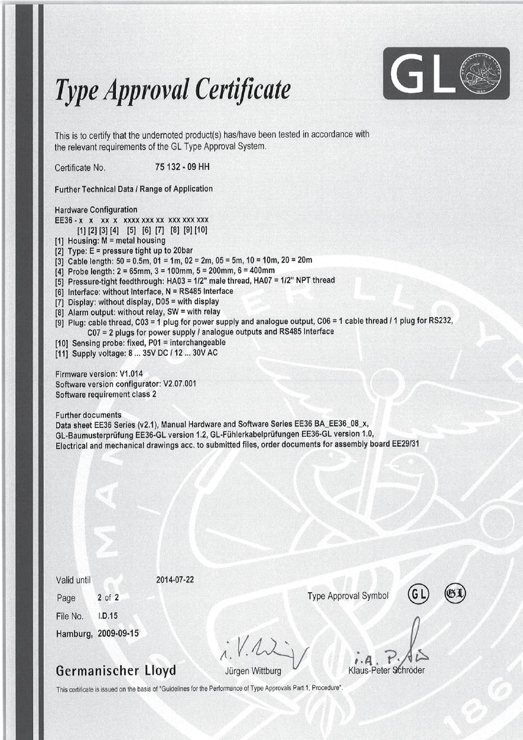
30 7. GL - APPROVAL CERTIFICATE 30
31 31
Series EE35 MANUAL. Hardware and Software INDUSTRIAL TRANSMITTER FOR DEWPOINT MEASUREMENT
 Series EE35 INDUSTRIAL TRANSMITTER FOR DEWPOINT MEASUREMENT MANUAL Hardware and Software BA_EE35_e // v13 / technical data are subject to change // 302297 E+E Elektronik Ges.m.b.H. doesn't accept warranty
EE360. High-End Moisture in Oil Transmitter. Typical applications. Features EE360 EE360. (+34)
") is dedicated for reliable monitoring of lubrication, hydraulic and insulation oils as well as diesel fuel. In addition to highly accurate measurement of water activity (a w ) and temperature (T), calculates
is dedicated for reliable monitoring of lubrication, hydraulic and insulation oils as well as diesel fuel. In addition to highly accurate measurement of water activity (a w ) and temperature (T), calculates
HLX31 Series. Multifunctional Industrial Transmitter for Humidity / Temperature / Dew Point / Absolute Humidity... Model A. Model B.
 Series The precise and reliable measurement of humidity in industrial processes is gaining more and more importance. The multifunctional transmitters series offer the ideal solution. The result of many
Manual EE371. Dew Point Transmitter / Switch down to -60 C Td. BA_EE371_e // V2.0 // technical data are subject to change
 Manual EE371 Dew Point Transmitter / Switch down to -60 C Td BA_EE371_e // V2.0 // technical data are subject to change E+E Elektronik Ges.m.b.H. doesn't accept warranty and liability claims neither upon
EE35. Industrial Transmitter for Dew Point Measurement. Autocalibration. Installation. Alarm Output. Integrated power supply. Typical Applications
 EE35 Industrial Transmitter for Dew Point Measurement Exact dew point monitoring is increasingly playing a more important role in many industrial applications, such as drying processes, air pressure pipelines,
Environmental Conditions C - remote sensing probe up to 120 C (248 F)
") EE33 Humidity / Temperature Transmitter for High Humidity and Chemical Applications The highly accurate EE33 series are designed for fast and reliable measurement of relative humidity / dew point temperature
EE33 Humidity / Temperature Transmitter for High Humidity and Chemical Applications The highly accurate EE33 series are designed for fast and reliable measurement of relative humidity / dew point temperature
EE32/33 Series. Humidity / Temperature Transmitter for High Humidity and Chemical Applications. Typical Applications. Features
 EE32/33 Series Humidity / Temperature Transmitter for High Humidity and Chemical Applications The highly accurate EE32/33 series are designed for fast and reliable measurement of relative humidity / dew
EE310. High-End Humidity and Temperature Transmitter for Demanding Process Control. Typical applications. Features EE310 EE310
 High-End Humidity and Temperature Transmitter for Demanding Process Control is optimized for reliable measurement in demanding industrial applications. In addition to highly accurate measurement of relative
TPM 80. Dew Point Transmitter. Manual. BA_TPM80_e // V1.0 // technical data are subject to change
 TPM 80 Dew Point Transmitter Manual BA_TPM80_e // V1.0 // technical data are subject to change Pro air doesn t accept warranty and liability claims neither upon this publication nor in case of improper
EE310. High-End Humidity and Temperature Transmitter for Demanding Process Control. Typical applications. Features EE310 EE310
 is optimized for reliable measurement in demanding industrial applications. In addition to highly accurate measurement of relative humidity (RH) and temperature (T), the transmitter also calculates parameters
USER S GUIDE. EE210 - Humidity and Temperature Transmitter for demanding Climate Control Applications GENERAL
 USER S GUIDE EE210 - Humidity and Temperature Transmitter for demanding Climate Control Applications GENERAL The EE210 transmitter, available for wall or duct mounting, is designed for the highly accurate
sensor, which compensates for ageing effects, is highly insensitive to pollution and offers outstanding long term stability.
 USER S GUIDE EE800 - HVAC Room Transmitter for CO 2, Temperature and Relative Humidity GENERAL EE800 combines CO 2, temperature (T) and relative humidity (RH) measurement in one device with modern design.
EE160 - Humidity and Temperature Transmitter for HVAC Applications
 USER S GUIDE EE160 - Humidity and Temperature Transmitter for HVAC Applications GENERAL The EE160 transmitter, available for wall or duct mounting, is designed for the measurement of humidity and temperature
EE75 Series. Manual. Hardware and Software. Air / Gas Velocity Transmitter. BA_EE75_e_12// technical data subject to change //
 EE75 Series Air / Gas Velocity Transmitter Manual Hardware and Software BA_EE75_e_12// technical data subject to change // 192310 E+E Elektronik Ges.m.b.H. doesn't accept warranty and liability claims
EE671 - Miniature Air Flow Transmitter
 USER s guide EE671 - Miniature Air Flow Transmitter GENERAL The EE671 air velocity transmitter operates on the hot-film anemometer principle and features an innovative, very robust E+E sensing element
USER S GUIDE. EE211 - Heatead Humidity and Temperature Transmitter for High Humidity Applications GENERAL ASSEMBLY SCOPE OF SUPPLY CAUTION
 USER S GUIDE EE211 - Heatead Humidity and Temperature Transmitter for High Humidity Applications GENERAL The EE211 is dedicated for accurate, long term stable measurement under high humidity and condensing
In order to minimize the impact of rain, snow, ice and solar radiation on the measurement the EE33-M must be mounted inside a radiation shield.
 Humidity and Temperature Transmitter for High-end Meteorological Applications E33-M is optimized for reliable measurement under demanding weather conditions. Besides accurate measurement of relative humidity
Insertion Flowmeter for compressed air and gases DN50 - DN700 (2-28 )
") The flow meter is based on the thermal mass flow measurement and is ideal for measuring the flow of compressed air and gases in pipes from DN50 (2 ) to DN700 (28 ). With the, the consumption of compressed
The flow meter is based on the thermal mass flow measurement and is ideal for measuring the flow of compressed air and gases in pipes from DN50 (2 ) to DN700 (28 ). With the, the consumption of compressed
EE210. Humidity and Temperature Transmitter for Demanding Climate Control. Applications. Features. 36 v2.5 / Modification rights reserved EE210
 Humidity and Temperature Transmitter for Demanding Climate Control The transmitter by E+E Elektronik meets the highest requirements in demanding climate control applications. Besides the accurate measurement
HDMI and USB KVM Extender
 HDMI and USB KVM Extender P/N 34898 User's Manual SAFETY WARNINGS AND GUIDELINES Please read this entire manual before using this device, paying extra attention to these safety warnings and guidelines.
HARDWARE GUIDE. Water Loop Controller C1000 Series. Specifications and Operational Guide
 HARDWARE GUIDE Water Loop Controller C1000 Series Specifications and Operational Guide www.proloncontrols.com info@proloncontrols.com 17 510, rue Charles, Suite 100, Mirabel, QC, J7J 1X9 REV. 6.1.6 PL-HRDW-WLC-C1000-C/F-EN
HD40H(X) Performance Series Camera. User Guide
 Performance Series Camera. User Guide") HD31H(X) HD30H(X) HD40H(X) Performance Series Camera User Guide Document 1 2 HD40H(X)/HD30H(X)/HD31H(X) Camera User Guide Thank you for purchasing our product. If there are any questions, or requests,
HD31H(X) HD30H(X) HD40H(X) Performance Series Camera User Guide Document 1 2 HD40H(X)/HD30H(X)/HD31H(X) Camera User Guide Thank you for purchasing our product. If there are any questions, or requests,
MC 11 EB-2 Power supply cabinet with external bus, AC version
 MC 11 EB-2 Power supply cabinet with external bus, AC version USER/MAINTENANCE MANUAL 1 SLOT 0 SLOT 1 SLOT 2 SLOT 3 SLOT 4 SLOT 5 SLOT 6 SLOT 7 SLOT 8 SLOT 9 SLOT 10 SLOT 11 EB-2 (a) MC11 (b) (c) Figures
DXTH DUCT SENSOR / SWITCH FOR TEMPERATURE AND HUMIDITY. Mounting and operating instructions
 DUAL DUCT SENSOR / SWITCH FOR TEMPERATURE AND HUMIDITY Mounting and operating instructions Table of contents SAFETY AND PRECAUTIONS 3 PRODUCT DESCRIPTION 4 ARTICLE CODES 4 INTENDED AREA OF USE 4 TECHNICAL
MONOPRICE. Blackbird 4K Pro 1x2 Ultra Slim HDMI Splitter. User's Manual P/N 21612
 MONOPRICE Blackbird 4K Pro 1x2 Ultra Slim HDMI Splitter P/N 21612 User's Manual SAFETY WARNINGS AND GUIDELINES Please read this entire manual before using this device, paying extra attention to these safety
WCC100 IN-VEHICLE CHARGING CRADLE OWNER S MANUAL
 WCC100 IN-VEHICLE CHARGING CRADLE OWNER S MANUAL 128-9237B WCC100 In-Vehicle Charging Cradle 12 03 13.indd 1 12/4/2013 10:38:04 AM 128-9237B WCC100 In-Vehicle Charging Cradle 12 03 13.indd 2 12/4/2013
SAFETY WARNINGS AND GUIDELINES
 1 SAFETY WARNINGS AND GUIDELINES Do not expose this device to water or moisture of any kind. Do not place drinks or other containers with moisture on or near the device. If moisture does get in or on the
Cardax Prox Plus Mifare Reader
 Installation Note Cardax Prox Plus Mifare Reader CAUTION This equipment contains components that can be damaged by electrostatic discharge. Ensure both you and the equipment are earthed before beginning
Now with Picture Memory
 Intrasonic Technology, Inc. Color Video Door Phone / Intercom Installer s Manual Model No.V304KIT-R Now with Picture Memory Please read this manual carefully before the products are installed.technical
Operating Manual UMB ISO Converter ISOCON Order Number: 8160.UISO
 Order Number: 8160.UISO Status: V3; 17.09.2010c G. Lufft Mess- und Regeltechnik GmbH, Fellbach, Germany 1 TABLE OF CONTENTS PLEASE READ BEFORE USE... 3 DESCRIPTION... 5 UMB ISO CONVERTER ISOCON... 6 CONFIGURATION...
Contents Safety precautions Product components Optional accessories Names of each parts Product Dimension Cables and Connectors Power Connection
 Contents Safety precautions Product components Optional accessories Names of each parts Product Dimension Cables and Connectors Power Connection LAN Connection RS485 Connection Relay Connection Digital
EE80 Series. HVAC Room Transmitter and Switches for CO 2, Relative Humidity and Temperature EE80. Applications. Typical
 EE80 Series HVAC Room Transmitter and Switches for, Relative Humidity and Temperature EE80 series set new standards in measurements for HVAC. The transmitters resp. switches combine, relative humidity
MONOPRICE. ShowPony 12-Watt LED Derby FX Light (RGBW) User's Manual P/N
 User's Manual P/N") MONOPRICE ShowPony 12-Watt LED Derby FX Light (RGBW) P/N 612900 User's Manual CONTENTS SAFETY WARNINGS AND GUIDELINES... 3 FEATURES... 5 CUSTOMER SERVICE... 5 PACKAGE CONTENTS... 5 DIMENSIONS DIAGRAM...
MONOPRICE ShowPony 12-Watt LED Derby FX Light (RGBW) P/N 612900 User's Manual CONTENTS SAFETY WARNINGS AND GUIDELINES... 3 FEATURES... 5 CUSTOMER SERVICE... 5 PACKAGE CONTENTS... 5 DIMENSIONS DIAGRAM...
Manual EE355. Dew Point Transmitter down to -60 C Td. BA_EE355_e // V1.3 // technical data are subject to change
 Manual EE355 Dew Point Transmitter down to -60 C Td BA_EE355_e // V1.3 // technical data are subject to change E+E Elektronik Ges.m.b.H. doesn t accept warranty and liability claims neither upon this publication
EE211. Humidity and Temperature Transmitter for Continuous High Humidity. Features. 42 v1.3 / Modification rights reserved EE211 EE211
 Humidity and Temperature Transmitter for Continuous High Humidity The is dedicated for accurate and long term stable measurement under continuous high humidity (>85 % RH) and condensing conditions in demanding
DSTHM-2 COMBINED T AND RH DUCT TRANSMITTER. Mounting and operating instructions
 Mounting and operating instructions Table of contents SAFETY AND PRECAUTIONS 3 PRODUCT DESCRIPTION 4 ARTICLE CODES 4 INTENDED AREA OF USE 4 TECHNICAL DATA 4 STANDARDS 4 OPERATIONAL DIAGRAMS 5 WIRING AND
RTT2 ROOM TEMPERATURE SWITCH. Mounting and operating instructions
 Mounting and operating instructions Table of contents SAFETY AND PRECAUTIONS PRODUCT DESCRIPTION ARTICLE CODES INTENDED AREA OF USE TECHNICAL DATA STANDARDS OPERATIONAL DIAGRAMS WIRING AND CONNECTIONS
Installation instructions RF-identification system with integrated AS-i slave DTSLF / / 2010
 Installation instructions RF-identification system with integrated AS-i slave UK DTSLF 704153 / 07 04 / 2010 Inhalt 1 Preliminary note...4 1.1 Symbols used...4 2 Safety instructions...4 2.1 General...4
Bluetooth Enabled Access Control MODEL BG-FE. Operating Instructions
 BlueGuard FE Bluetooth Enabled Access Control MODEL BG-FE Operating Instructions CAUTION AND SAFETY INFORMATION IMPORTANT: If the equipment is used in a manner not specified in this manual, the protection
MONOPRICE. Blackbird 4x4 HDMI Matrix/Extender with 4 Receivers. User's Manual P/N 21905
 MONOPRICE Blackbird 4x4 HDMI Matrix/Extender with 4 Receivers P/N 21905 User's Manual CONTENTS SAFETY WARNINGS AND GUIDELINES... 3 INTRODUCTION... 4 FEATURES... 4 CUSTOMER SERVICE... 5 PACKAGE CONTENTS...
COMMERCIAL. VAM24-90-(A) Series Installation Instructions
 Series Installation Instructions") MERCIAL VAM24-90-(A) Series Installation Instructions Bray Controls Commercial Division 13788 West Road, Suite 200A Houston, Texas 77041 BCDSales@Bray.com Phone: 1-888-412-2729 Fax: 1-888-412-2720 www.braycommercialdivision.com
MERCIAL VAM24-90-(A) Series Installation Instructions Bray Controls Commercial Division 13788 West Road, Suite 200A Houston, Texas 77041 BCDSales@Bray.com Phone: 1-888-412-2729 Fax: 1-888-412-2720 www.braycommercialdivision.com
Operation manual EE310. Humidity/Temperature Transmitter. BA_EE310_e // V2.1 // Technical data subject to change //
 Operation manual EE310 Humidity/Temperature Transmitter BA_EE310_e // V2.1 // Technical data subject to change // 194474 E+E Elektronik Ges.m.b.H. provides no warranty of any kind for this publication
Table of Contents. Federal Communications Commission (FCC) Statement...2
 Statement...2") Contents Table of Contents Federal Communications Commission (FCC) Statement...2 Important Safety Instructions...3 Chapter 1 Introduction Features...6 Package Contents...7 Front View and Controls...8 Installing
Contents Table of Contents Federal Communications Commission (FCC) Statement...2 Important Safety Instructions...3 Chapter 1 Introduction Features...6 Package Contents...7 Front View and Controls...8 Installing
ShoreTel IP Phone 655. Quick Install Guide & Warranty
 ShoreTel IP Phone 655 Quick Install Guide & Warranty Document and Software Copyrights Copyright 1998-2012 by ShoreTel Inc., Sunnyvale, California, USA. All rights reserved. Printed in the United States
Control different load types with one device
 Multipurpose Controllers DMC2 Multipurpose Modular Controller Control different load types with one device The Philips Dynalite DMC2 provides multichannel control via two interchangeable output modules.
INSTALLATION GUIDE DM-20 English Version 1.10 EN DM20 V1.10A
 www.supremainc.com INSTALLATION GUIDE DM-20 English Version 1.10 EN 101.00.DM20 V1.10A Contents Safety Instructions... 3 Components... 4 Front Side... 5 Installation Example... 6 Dimensions... 7 Installation...
EE870 Modular CO 2 Transmitter
 EE870 Modular CO 2 Transmitter Manual BA_EE870_e // v1.5 // Technische Änderungen vorbehalten E+E Elektronik Ges.m.b.H. doesn't accept warranty and liability claims neither upon this publication nor in
Type Quickstart (from device Version 2)
") Type 8022 Flow Transmitter / Pulse divider Durchflusstransmitter / Impulsteiler Transmetteur de débit / Diviseur d impulsions We reserve the right to make technical changes without notice. Technische Änderungen
Type 8022 Flow Transmitter / Pulse divider Durchflusstransmitter / Impulsteiler Transmetteur de débit / Diviseur d impulsions We reserve the right to make technical changes without notice. Technische Änderungen
Original operating instructions Fail-safe inductive sensor GI711S / / 2010
 Original operating instructions Fail-safe inductive sensor GI7S 704583 / 0 06 / 200 Contents Preliminary note 3. Explanation of symbols 3 2 Safety instructions 4 2. Safety-related requirements regarding
Ball Probe Moisture Meter With Bluetooth
 User Manual Ball Probe Moisture Meter With Bluetooth Model MR59 Table of Contents 1. Advisories... 3 1.1 Copyright... 3 1.2 Quality Assurance... 3 1.3 Documentation... 3 1.4 Disposal of Electronic Waste...
RТTH DUAL ROOM SWITCH
 DUAL ROOM SWITCH FOR TEMPERATURE AND RELATIVE HUMIDITY Mounting and operating instructions Table of contents SAFETY AND PRECAUTIONS PRODUCT DESCRIPTION ARTICLE CODES INTENDED AREA OF USE TECHNICAL DATA
elise 3 embedded linux server including safety instructions
 elise 3 embedded linux server including safety instructions Contents Getting Started... 2 Safety and Regulatory Instructions for Elise3... 8 English Getting Started These instructions will help you getting
2 Mesa Ethernet Dock User s Manual
 owner s manual Mesa Ethernet Dock The Mesa Ethernet Dock is an optional accessory that provides an ethernet port for networking, power input jack, USB client port, and a mounting station for the Mesa Rugged
Original operating instructions Fail-safe inductive sensor GF711S / / 2013
 Original operating instructions Fail-safe inductive sensor GF7S 8528 / 5 / 23 Contents Preliminary note...3. Explanation of symbols...3 2 Safety instructions...4 2. Safety-related requirements regarding
CPCI-PS24 24V-Power Supply
 24V-Power Supply Hardware Manual to Product I.2301.21 esd electronic system design gmbh Vahrenwalder Str. 207 30165 Hannover Germany http://www.esd.eu Phone: +49 (0) 511 3 72 98-0 Fax: +49 (0) 511 3 72
USER GUIDE. AXIS T8120 Midspan 15 W 1-port ENGLISH
 USER GUIDE AXIS T8120 Midspan 15 W 1-port ENGLISH Legal Considerations Video and audio surveillance can be prohibited by laws that vary from country to country. Check the laws in your local region before
*520886* IntelliTouch Pool & Spa Control System MobileTouch Wireless Controller. User s and Installation Guide. P/N Rev A
 pool/spa control system IntelliTouch Pool & Spa Control System MobileTouch Wireless Controller User s and Installation Guide P/N 520886 - Rev A *520886* i MobileTouch Wireless Controller kit contents The
User Guide Microsoft Portable Power (DC-21)
") User Guide Microsoft Portable Power (DC-21) Issue 1.0 EN-US User Guide Microsoft Portable Power (DC-21) Contents For your safety 3 About your portable charger 4 Keys and parts 5 Charge your portable charger
User Guide Microsoft Portable Power (DC-21) Issue 1.0 EN-US User Guide Microsoft Portable Power (DC-21) Contents For your safety 3 About your portable charger 4 Keys and parts 5 Charge your portable charger
The following symbols are used to show dangerous operation or handling. Make sure you understand them before reading the guide.
 Safety Instructions Before use Thank you very much for purchasing this product. This product is an interface box called "Connection & Control Box" for EPSON short throw projectors. For your safety, read
5 B&W Rear View System Camera
 5 B&W Rear View System Camera Instruction Manual MODEL: CA453 www.lorexcctv.com Copyright 2007 LOREX Technology Inc. Thank you for purchasing the Lorex 5 Black & White Rear View System Camera. This system
HARDWARE GUIDE. Boiler Controller M2000 Series. Specifications and Operational Guide
 HARDWARE GUIDE Boiler Controller M2000 Series Specifications and Operational Guide www.proloncontrols.com info@proloncontrols.com 17 510, rue Charles, Suite 100, Mirabel, QC, J7J 1X9 REV. 6.1.9 PL-HRDW-BLR-M2000-C/F-EN
Operating Instructions VEGAMET 381
 Operating Instructions VEGAMET 381 in out Contents Contents 1 About this document... 4 1.1 Function... 4 1.2 Target group... 4 1.3 Symbolism used... 4 2 For your safety... 6 2.1 Authorised personnel...
Handset Charging Rack OpenStage WL 3 / OpenStage WL3 Plus. Installation Guide A31003-M2000-J
 Handset Charging Rack OpenStage WL 3 / OpenStage WL3 Plus Installation Guide A31003-M2000-J102-2-7631 Our Quality and Environmental Management Systems are implemented according to the requirements of the
Installation Instructions RF5010 and RF5210
 Installation Instructions RF5010 and RF5210 HES, Inc. 2260 N. 17th Ave. Phoenix, AZ 85027 800-626-7590 1 Product Description Dimensions Orientation Compatibility Access Control Systems Proximity Cards
FILTER NAME CONSTRUCTION FEATURES APPLICATIONS ORDER CODE MEMBRANE Body: polycarbonate Filter: PTFE membrane
 Filter Caps for Humidity and Dewpoint Transmitters with probe 12 mm (0.47 ) The right choice of appropriate filter cap is essential for best long term performance in the application. For assistance please
The Solution. Multi-Input Module IMPORTANT: READ AND UNDERSTAND ALL INSTRUCTIONS BEFORE BEGINNING INSTALLATION
 The Solution Multi-Input Module INSTALLATION INSTRUCTIONS Model: MIM-62 IMPORTANT: READ AND UNDERSTAND ALL INSTRUCTIONS BEFORE BEGINNING INSTALLATION MIM-62 connects up to 6 monitored entrapment protection
X-12s Users Manual. X-12s User Manual Revisions Revision Description Initial release. Xytronix Research & Design, Inc.
 X-12s User Manual Revisions Revision Description 1.0 Page 2 Initial release Introduction Section 1: Introduction The X-12s 8-Relay expansion module is used with the X-600M controller. The X-12s has eight
Intrinsically safe batch controller Batching Master 110i
 Intrinsically safe batch controller Batching Master 110i Installation Guide BVS 04 AT E 172 Revision 12.2 IBS BatchControl GmbH Im Sträßchen 2-4 Tel.: ++49 2441 9199 801 53925 Kall Fax.: ++49 2441 9199
The following symbols are used to show dangerous operation or handling. Make sure you understand them before reading the guide.
 Safety Instructions Before use Thank you very much for purchasing this product. This product is an interface box called "Connection & Control Box" for EPSON short throw projectors. For your safety, read
Manual Control Unit GFC 32
 Manual Control Unit 1400004_EN/05.2017 Index 1. Main features 3 2. Technical features 3 3. Installation guidelines 4 4. Preliminary checks 5 5. Electrical connections 5 6. Settings 6 7. Remote control
InBin-P Pressure switches from 5 Pa Pa
 InBin-P Pressure switches from 5 Pa...100 Pa Electrical, binary pressure or differential pressure switches with adjustable switch activation delay 24 VAC/DC supply voltage, potential free switching contact
Cardax FT Controller 3000
 Installation Note Cardax FT Controller 000 CAUTION This equipment contains components that can be damaged by electrostatic discharge. Ensure both you and the equipment are earthed before beginning any
EE75 Series. High-Precision Air / Gas Velocity Transmitter for Industrial Applications. Model A. Model B. Model C. Typical Applications.
 Series High-Precision Air / Gas Velocity Transmitter for Industrial Applications The series air velocity transmitters were developed to obtain accurate measuring results over a wide range of velocities
INSTALLATION INSTRUCTIONS
 INSTALLATION INSTRUCTIONS Adaptor Model No. CZ-CFUNC1U For your safety Read the following instructions carefully, and carry out secure installation and electrical work. The precautions given in this manual
FR-IB100/PCIe. FlexRay PCI Express Interface Card USER MANUAL ENGLISH
 FR-IB100/PCIe FlexRay PCI Express Interface Card USER MANUAL 4.01.0103.20000 2.0 ENGLISH Important User Information Liability Every care has been taken in the preparation of this document. Please inform
B-33. Hardware and Install Manual. (DC 12V / PoE)
") B-33 Hardware and Install Manual (DC 12V / PoE) Table of Contents Precautions 3 Safety Instructions... 4 Introduction 6 Package Contents... 6 Physical Description... 7 Installation Procedures 9 Step 1:
B-33 Hardware and Install Manual (DC 12V / PoE) Table of Contents Precautions 3 Safety Instructions... 4 Introduction 6 Package Contents... 6 Physical Description... 7 Installation Procedures 9 Step 1:
RXTH DUAL ROOM SENSOR / SWITCH
 DUAL ROOM SENSOR / SWITCH FOR TEMPERATURE AND RELATIVE HUMIDITY Mounting and operating instructions Table of contents SAFETY AND PRECAUTIONS 3 PRODUCT DESCRIPTION 4 ARTICLE CODES 4 INTENDED AREA OF USE
Operating instructions. Speed monitor D / / 2014
 Operating instructions Speed monitor D200 80005257 / 00 05 / 2014 Contents 1 Preliminary note...4 1.1 Symbols used...4 1.2 Warning signs used...4 2 Safety instructions...5 2.1 General...5 2.2 Target group...5
MONOPRICE. Blackbird HDMI Bi-Directional Switch. User's Manual P/N 24280
 MONOPRICE Blackbird HDMI Bi-Directional Switch P/N 24280 User's Manual SAFETY WARNINGS AND GUIDELINES Please read this entire manual before using this device, paying extra attention to these safety warnings
FEMTOCELL MULTI-BAND SOHO B2/B4 (SS2FII)
") FEMTOCELL MULTI-BAND SOHO B2/B4 (SS2FII) Table of Contents Welcome... 3 Box Content... 4 Connection Overview... 5 Quick Setup... 6 Common Troubleshooting Procedures... 10 FAQs... 11 2 Welcome The Femtocell
FEMTOCELL MULTI-BAND SOHO B2/B4 (SS2FII) Table of Contents Welcome... 3 Box Content... 4 Connection Overview... 5 Quick Setup... 6 Common Troubleshooting Procedures... 10 FAQs... 11 2 Welcome The Femtocell
accurate measurement of compressed air consumption and leakage detection Calibration certificates and continous calibration, OEKD calibration service
 Series Flowmeter for compressed air and gases in Industrial Applications The flowmeter of the series, based on the measurement principle of thermal mass flow, is ideally suited for the measurement of flow
2-Port Serial-to-IP Ethernet Device Server - RS232
 2-Port Serial-to-IP Ethernet Device Server - RS232 NETRS2322P *actual product may vary from photos FR: Guide de l utilisateur - fr.startech.com DE: Bedienungsanleitung - de.startech.com ES: Guía del usuario
Industriefunkuhren. Technical Manual. Signal Converter. for DIN Rail Mounting Series 4800xx-yy ENGLISH
 Industriefunkuhren Technical Manual Signal Converter for DIN Rail Mounting Series 4800xx-yy ENGLISH Version: 01.01-19.07.2007 2 / 23 Signal Converter 4800 - V01.01 INPORTANT NOTES Downloading Technical
3M Ground Master Equipment Ground Monitor Models CTC065-RT and CTC065-5 User s Guide
 3M Ground Master Equipment Ground Monitor Models CTC065-RT and CTC065-5 User s Guide Table of Contents Section Page Safety Statements...3 Intended Use...3 Specifications...4 Controls and Indicators...5
Clipsal Bus Couplers. Two Channel (SLC5102BCLEDL) and Four Channel (SLC5104BCL) for Use with C-Bus Wired Systems
 and Four Channel (SLC5104BCL) for Use with C-Bus Wired Systems") Clipsal Bus Couplers Two Channel (SLC5102BCLEDL) and Four Channel (SLC5104BCL) for Use with C-Bus Wired Systems Instruction Bulletin Retain for future use. Clipsal Bus Couplers 63249-420-236A2 Instruction
Clipsal Bus Couplers Two Channel (SLC5102BCLEDL) and Four Channel (SLC5104BCL) for Use with C-Bus Wired Systems Instruction Bulletin Retain for future use. Clipsal Bus Couplers 63249-420-236A2 Instruction
USER MANUAL. Model NAME : Anker USB 2.4G Wireless Vertical Mouse MODEL NO. : A VERSION : 0.1 DATE : A User Manual VER: 0.
 USER MANUAL Model NAME : Anker USB 2.4G Wireless Vertical Mouse MODEL NO. : A7809012 VERSION : 0.1 DATE : 2015.10.16 Page 1 of 8 Version. Revised Date PIC Remark # 0.1 16/10/2015 Bob Preliminary Page 2
InCos-P Pressure sensor 20 Pa Pa
 InCos-P Pressure sensor 20 Pa... 7.500 Pa Electrical pressure / differential pressure sensors 24 VAC/DC supply voltage, 0...10 V / (0) analogue Compact. Easy installation. Universal. Cost effective. Safe.
This document will show you how to set up the Hotwire 6205 ADSL Modem, and how to customize its configuration to get the most out of this product.
 Hotwire 6205 ADSL Modem Installation Instructions Document Number 6205-A2-GZ40-10 September 2004 Introduction Congratulations on becoming the owner of a Hotwire ADSL USB Modem. You will now be able to
User's Guide. Video Borescope Inspection Camera. Model BR70
 User's Guide Video Borescope Inspection Camera Model BR70 Introduction Congratulations on your purchase of this Extech BR70 Video Borescope. This instrument was designed for use as a remote inspection
This simple chassis houses one media-converter module and features an external AC power supply and also a terminal block for DC power input.
 LMC5103A-R2 1-slot Multipower Desktop Chassis (Module Not Included) This simple chassis houses one media-converter module and features an external AC power supply and also a terminal block for DC power
Daily use. indicating that the loud speakers
 BeoLab 8002 Guide WARNING: To reduce the risk of fire or electric shock, do not expose this appliance to rain or moisture. Do not expose this equipment to dripping or splashing and ensure that no objects
Electromotoric actuators Torques up to 60 Nm Running times ¹) s. ¹) Predefined by the basic unit (LMV5...)
 s. ¹) Predefined by the basic unit (LMV5...)") 7 818 Actuators SQM9... Electromotoric actuators Torques up to 60 Nm Running times ¹) 30...120 s ¹) Predefined by the basic unit (LMV5...) The SQM9... and this Data Sheet are intended for use by OEMs which
7 818 Actuators SQM9... Electromotoric actuators Torques up to 60 Nm Running times ¹) 30...120 s ¹) Predefined by the basic unit (LMV5...) The SQM9... and this Data Sheet are intended for use by OEMs which
DVI Splitter Amplifier DS01. User s Manual. Preliminary version Copyright 2012 SHENZHEN BIGTIDE TECHNOLOGY CO., LTD
 BIGTIDE SERVICE DOCUMENT DVI Splitter Amplifier DS01 Preliminary version Copyright 2012 SHENZHEN BIGTIDE TECHNOLOGY CO., LTD Contents 1. INTRODUCTION...2 2. SAFETY PRECAUTIONS...2 3. TECHNICAL INFORMATION...4
SPK User Manual. 900MHz Wireless Stereo Headphones INTRODUCTION FEATURES IMPORTANT SAFETY INFORMATION
 INTRODUCTION Thank you for purchasing our 900Mhz compact cordless stereo headphone system that takes advantage of the very latest advances in wireless transmission technology so you SPK-9100 900MHz Wireless
EX-RC1 Remote I/O Adapter
 EX-RC1 Remote I/O Adapter The EX-RC1 interfaces between Unitronics Vision OPLCs and remote I/O Expansion Modules distributed throughout your system. The adapter is connected to a PLC via CANbus. Each adapter
CAN Repeater CAN-CR200, CAN-CR220, CAN-CR210/FO USER MANUAL ENGLISH
 CAN Repeater CAN-CR200, CAN-CR220, CAN-CR210/FO USER MANUAL 4.01.0067.20000 3.1 ENGLISH Important User Information Liability Every care has been taken in the preparation of this document. Please inform
Optical distance sensors. Dimensioned drawing
 Optical distance sensors Dimensioned drawing en 03-2012/11 50110829 120 1400mm 18-30 V DC We reserve the right to make changes DS_ODS96BMV61400S12_en_50110829.fm Reflection-independent distance information
Emotiv Insight User Manual. Revision 1.0 June 2015 Emotiv Inc, 2015
 Emotiv Insight User Manual Revision 1.0 June 2015 Emotiv Inc, 2015 Before first use - check the parts are in the box - assemble the Insight - charge the Insight - obtain software - check operation - read
E2K-X4ME1 2M E2K-X4ME2 2M
 Cylindrical Proximity Sensor EK- CSM_EK-_DS_E 1 General-purpose Threaded Sensor That Detects Metals and Non-metals Alike Detects both metallic and nonmetallic objects (water, oil, glass, plastic, etc.).
RXTP ROOM TEMPERATURE
 ROOM TEMPERATURE CONTROLLER WITH PI CONTROL Mounting and operating instructions Table of contents SAFETY AND PRECAUTIONS 3 PRODUCT DESCRIPTION 4 ARTICLE CODES 4 INTENDED AREA OF USE 4 TECHNICAL DATA 4