OptiSystem Training Seminar optiwave.com optiwave.jp
|
|
|
- Annabel Booker
- 6 years ago
- Views:
Transcription


1 2009 Optiwave Systems, Inc. OptiSystem Training Seminar optiwave.com optiwave.jp
2 About Optiwave Systems Leader in the development of innovative software tools in Optics Design, simulation, and optimization of components, links, systems and networks for Photonics Nanotechnology, Optoelectronics, Optical Networks Established in 1994 Licensed in 1000 industry-leading corporations and universities in over 60 countries 2


3 Photonics design portfolio System design Time and frequency domain simulators for the design of the physical or transmission layer of optical systems, subsystems and components. Component design Unique circuit design software that incorporates equations governing optical elements into an electrical simulation framework to provide selfconsistent analysis of opto-electronic circuits Based on the Beam Propagation Method (BPM), simulates light field distribution through any waveguide medium Based on FDTD and UPML boundary condition, solves the E & H fields in both the spatial and temporal domains, for advanced passive and nonlinear photonic component design Based on Coupled Mode theory and the Transfer Matrix method, simulates the design of waveguide and fiber based periodic structures Using an array of mode solvers; calculates dispersion, material losses, birefringence, and PMD to aid in optimizing parameter selection for single and multi-mode fiber designs 3
 Single-mode/multi-mode transmission Free space optics (FSO), Radio over fiber (ROF), OFDM (direct,")
4 About OptiSystem OptiSystem is a time/frequency domain simulator for optical system design. Applications include: Optical network design (OTDM, SONET/SDH rings, CWDM, DWDM, PON, Cable, OCDMA) Single-mode/multi-mode transmission Free space optics (FSO), Radio over fiber (ROF), OFDM (direct, coherent) Amplifiers and lasers (EDFA, SOA, Raman, Hybrid, GFF optimization, Fiber Lasers) Signal processing (Electrical, Digital, All-Optical), Direct/Coherent Tx/Rx design Modulation formats (RZ, NRZ, CSRZ, DB, DPSK, QPSK, DP-QPSK, PM-QPSK, etc.) System performance analysis (Eye Diagram/Q-factor/BER, Signal power/osnr, Polarization states, Constellation diagrams, Linear and non-linear penalties) Default component library Customized components Co-simulation components System & Sub-system design layouts Signal representation & hierarchy between components, sub-systems, etc.: Binary Multilevel Electrical Optical Any type 4
5 2009 Optiwave Systems, Inc. OptiSystem Seminar Module 1: Overview of OptiSystem GUI features optiwave.com optiwave.jp
6 Module 1 OptiSystem GUI Overview Menu/tool bars Display properties Project layout Project browser Design & analysis tools Components overview Application examples Resources 6
 Projects tab")
7 OptiSystem GUI: Overview Default component library Custom Favorites Recently Used Tool bars Description docker Component library Layout Editor Project Browser Pan window Scaled view of layout Component inventory/data for all layouts associated with a Project Layout tab(s) Projects tab 7
 Search for")


8 OptiSystem GUI: Component library Default library 400+ components (16 libraries) Search for components via Find component or Browse features Custom Create user-defined components and sub-systems Favorites Add most often used components Recently used Display most recently used components (up to 10) 8

9 OptiSystem GUI: Menu/Tool bar functions (1) Open project Print current project Undo, Redo Calculate Visualizers Layout menu bar Set total sweep iterations Previous. Next sweep iterations New project Save current project Cut, copy, paste Calculate Add, Duplicate layouts Delete current layout Set current iteration Parameter sweeps Layout size, parameters and properties Generate script Save script Performer settings Export Performer Component, Project and Description dockers Run script Load script Find script 9
10 OptiSystem GUI: Menu/Tool bar functions(2) Layout tool Monitor tool Draw output port Draw input port Draw path Draw rectangle Draw circle Draw line Draw text label Bit map tool Zoom in Zoom out Zoom to window Zoom 1:1 Auto-connect on drop Auto-connect on move View component parameters View port signal data View component results 10
11 OptiSystem GUI: File menu functions 11
12 OptiSystem GUI: Edit menu functions (1) Layout tools. Also available via menu bars Component tools. Also available via project layout context tool 12

13 OptiSystem GUI: Edit menu functions (2) Also available via project layout context tool 13

14 OptiSystem GUI: View menu functions Also available via project layout context tool 14
15 OptiSystem GUI: Layout menu functions Also available via project layout context tool 15
16 OptiSystem GUI: Tools/Report/Help menu Also accessed via the Calculations dialog box Use this function (or the shortcut) to add new report pages Provides access to html help version of the User Reference guide 16

17 OptiSystem GUI: Display properties Access via Tools/Options 17


18 Project layout: Layout properties Name, author and date is reflected within the Layout properties header 18


19 Project layout: Accessing/modifying components View or modify all parameters linked to a component Enable or disable for simulation Access results (when available) following a calculation Create a VB script that is specific to the component 19

20 Project layout: Working with components in the layout Select links (left-click) to either delete or adjust their position Select/Copy/Delete Select individual components, or highlight groups of components; to duplicate, move or delete Drag and drop components from libraries Links Can auto-connect on drop or move or manually from an output port to an input port Non-compatible connections are flagged Monitors/Visualizers Monitors are automatically created when visualizers are attached Multiple visualizers can be connected to an output port Connections are represented by dotted lines 20


21 Project layout: Layout depth order Component and sub-systems can be allocated to different layers to simplify complicated or dense layouts 21
22 Project layout: Component properties/parameters Parameters are grouped by categories and define the input characteristics and simulation settings for the component Components can be disabled by unselecting the Enabled parameter in the Simulation tab Access component properties by double clicking on a component or by right-clicking and selecting Component Properties Parameters can either be defined directly (Normal), by using a formula/script (Script) or swept between a set of a data points (Sweep). When selected, and when View component parameters is on, the parameter value will be displayed below the component in the layout editor 22


23 Project layout: Visualizers properties/parameters Access visualizers by right clicking and selecting Component Properties Parameters used to defined measurement and graph settings 23
 to access Port")


24 Project layout: Port properties Hover mouse over port (and right-click) to access Port Properties Label information and port position/location can only be modified for sub-systems Determine which signal data to view when View port signal data is activated. 24

 It is important to keep monitors to a minimum to reduce memory requirements!")
25 Project layout: Data monitors & signal tracing Port data appears (after calculation) when View Port Signal data is selected Note: Calculate signal tracing must also be enabled in Global Parameters Select monitor tool and hover over output ports that you wish to add or remove data monitors Data monitors Data passed through ports can have large amounts of data (this data is saved only at ports where monitors are present) It is important to keep monitors to a minimum to reduce memory requirements! 25


26 Project layout: Adding objects and text Double click on objects to modify line and fill colors Basic tools: Lines, rectangles, circles/ellipses Add images (bit map, jpeg) to the layout Create text boxes and edit text type, font and colour 26


27 Project layout: Bill of Materials Defined in the Custom order tab for Component properties 27

28 Project browser: Overview Global layout settings including Global parameters, Sweeps and Paths Data on each component includes: Ports Parameters Results (when applicable) Graphs (when applicable) Lists all information for a project The components in the project layout are synchronized with those in the project browser view (when you click a component in the project browser, the same component is selected in the layout (and vice versa)) All information linked to any component (or the layout) can be viewed through an expandable menu tree structure 28

29 Project browser: View settings Create and access customized views 29
30 Design and analysis tools: Visualizers Optical / RF Spectrum Analyzer Resolution filter, Signal analysis Oscilloscope Amplitude, Power, Chirp EYE Diagram Analyzer Masks and Histograms BER Analyzer Numerical and quasi-analytical analysis WDM Analyzer Calculate power, wavelengths, S/N ratios Signal Analyzer Statistical analysis 30


31 Design and analysis tools: Path tool 31

32 Design and analysis tools: Graphs The graphic icons (2D/3D) appear for all graphs that can be viewed Double-click, or right click and select Quick view, to preview the graph results The Component view feature can also be used to visualize 2D and 3D graphs 32


33 Design and analysis tools: Results Displays values representing calculated data generated by a component Cab be accessed via Project browser, Component view and Component Results Checked values will be displayed in the project layout (just below the component) If a calculated value is outside the min-max points, it will be displayed in a red font 33

34 Design and analysis tools: Reports Create Tables 2D Graphs 3D Graphs Plot parameters vs. results 34
35 Design and analysis tools: Scripts Uses standard VB script language. Allows changes in the parameters of current project. Can be used for postprocessing of simulation results. 35


36 Design and analysis tools: Optimizations Single-parameter optimization Multiple-parameter optimization GFF optimization Monte Carlo Yield Estimate 36


37 Design and analysis tools: Co-simulation Matlab component Scilab component Optiwave SW tools OptiGrating OptiBPM OptiSPICE Agilent EDS file transfer 37
38 Components overview 38
39 Application examples 39


40 Digital Link Design Using Different Modulation Formats RZ, NRZ Duobinary CSRZ DPSK DQPSK 100 km 165 km 180 km 40

41 WDM Systems DWDM CWDM 41


42 Multimode Link 42

43 Ring Network 43


44 Metro Network 44

45 CATV Systems 45


46 Optical Amplifier Design EDFA YDFA EYDFA RFA 46

47 PON-Bidirectional Transmission 47

48 SCM Optical Transmission 48

49 Resources (1) Documentation OptiSystem Component Library OptiSystem Getting Started OptiSystem Tutorials Vol 1 & Vol 2 OptiSystem User Reference OptiSystem VBScripting Ref Guide Component help 49
50 Resources (2) Samples folder On-line examples Manuals (2012) Manuals 2012.zip (User: q236jd2; Pwd: r71de13) Customer support Phone: (OPTI)/ (Mon-Fri, Eastern) Feedback Optiwave community forum (User: perf38201, PW: login9371) 50
51 2009 Optiwave Systems, Inc. OptiSystem Seminar Module 2: System design optiwave.com optiwave.jp
52 Module 2 (1) Signals Global parameters Calculate tab overview Project 1: Transmitter External modulated laser Project layout Component parameters Visualizers Info-window features Project 2: Subsystems Hierarchical simulation Creating a sub-system with ports Subsystem properties Accessing global parameters Adding a custom component to the library 52
53 Module 2 (2) Project 3: Optical Systems WDM Designs Parameter groups Fiber/EDFA spans BER Analysis 3D graphs Project 4: Parameter Sweeps BER x Input power Setting up sweep iterations Browsing iteration results Analyzing results with Reports 53
 and optical pulse generators Sampled in time domain 54")
54 Signals: Types & representation Binary Sequences of 1 s & 0 s Created by bit sequence generators M-ary Multi-level discrete values for advanced modulation (PAM, QAM, QPSK) Electrical Generated by electrical pulse generators and photo-detectors Sampled in time domain Optical Generated by optical sources (e.g. lasers) and optical pulse generators Sampled in time domain 54
55 Signals: Electrical Noise power spectral densities in frequency domain. Sampled signal waveform in time domain. Signal noise variances in time domain. Pulse generators Create noise-less time domain sampled waveform Photo-detectors On top of time domain sampled waveform may contain information on time variance noise (shot) or power spectral density (thermal) 55
56 Signals: Optical Adaptive noise bins Parameterized Sampled signals Sampled signals (optical sources) Time domain representation of optical signal Can be represented in independent bands or in the same continuous frequency band Spatial mode data is also available Parameterized signals Time-averaged descriptions of sampled signals (Average power, Central frequency, and Polarization state) Useful for performing a fast estimation of system performance (power budget, OSNR) Noise bins Represent optical noise via average spectral density in two polarizations (power spectral density x bandwidth) Propagated separately from the optical sampled signals (but can be combined with signals for overlapping bands 56
 The global Bit rate can affect components such as Bit sequence generators (which may use as a default value) and the value for the bandwidth or cut-off")
57 Global parameters: Simulation tab Set bit rate (Default mode) Set time window Set sample rate When enabled, closest Time window or Sample rate is found Set by the user Set by the user Always calculated (Sequence length X Samples/bit) The global Bit rate can affect components such as Bit sequence generators (which may use as a default value) and the value for the bandwidth or cut-off frequency of most electrical filters. The Time window affects all components (each component works with the same time window). This parameter is best expressed in terms of the sequence length and the bit rate used during the simulation. The global Sample rate specifies the frequency simulation window or simulation bandwidth in Hz. It can affect components such as pulse generators and optical sources that generate signals at different sample rates. It is normally best to operate all modules in the design at the same sample rate The Sequence length should be set based on the simulation objectives. Use long sequences for transmission metrics (such as eye diagrams & BER) and short sequences to study optical effects (such as pulse dispersion) 57
58 Global parameters: Simulation basics Defines the frequency spacing in the freq domain. TW = Seq. length X Bit period Df = 1/Time window = Sample rate/# samples Time domain samples = Freq domain samples Samples per bit Time spacing = 1/Sample rate The Samples per bit, or the number of samples taken over a bit period (0 or 1), must be a power of two (2, 4, 8, 16, ). The sampling rate is automatically adjusted after Samples per bit is changed The Sequence length, the number of bits that are captured within a given time (or sampling) window in seconds, must also be a power of two. The Sampling rate is calculated by taking the inverse of the sampling time T (the time interval between performing measurements on the analog signal). If the highest known or expected frequency component (non-negligible) of the signal stream is Fsample, then the sampling rate should be set to at least 2 X Fsample (Nyquist rate) to ensure good fidelity of the reconstructed signal. 58


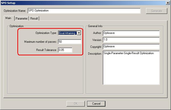
59 Global parameters: Simulation tab (GPU) 59
60 Global parameters: Signals tab Iterations Number of signal blocks generated by each simulation. It mainly affects transmitters and components used in bidirectional simulations and in network ring design. By increasing the parameter iterations a component will repeat the previous calculation until the number of calculations is equal to the iterations. Initial Delay This parameter forces a component to generate a null signal at each output port. It affects all components and it is mainly used in bidirectional simulations. The user does not have to add delays at the component input ports if using this parameter. Parameterized Defines whether the signal output will be sampled signals (disabled) or parameterized signals (enabled). It can affect components such as optical sources and optical pulse generators. 60


61 Global parameters: Spatial effects tab The spatial effects parameters affect components that generate spatial modes, where the discretization space and the level of the discretization should be defined. The number of points per spatial mode is defined as the product of the number of points in the X and Y 61

62 Global parameters: Signal tracing tab dbm, W or mw Hz, m, THZ or nm Defines if noise floor will be calculated using interpolation OptiSystem allows for fast estimation of power and noise at each output port. This estimation is calculated every time a signal is sent to the component output port. The signal tracing parameters allow the user to control the calculation and presentation of the results 62

63 Calculate tab overview Setup optimizations for layout Start calculation Pause calculation Stop calculation Disables & cleans the signal buffers at the end of the calculation. When disabled, user can perform large number of sweeps. Calculate the whole project Calculates all the layouts and all the sweep iterations within each layout. Calculate all sweep iterations in the active layout Calculates all the sweep iterations within the current active layout only. Calculate current sweep iteration Calculates only the selected sweep iteration in the current layout. 63

64 Project 1: Transmitter External modulated laser 64
 and may comprise a group of components or other")
65 Project 2: Subsystems hierarchical simulation OS allows for the creation of multiple layers of subsystems. Subsystems are identical to components (icons, parameters, ports) and may comprise a group of components or other subsystems. 65


66 Project 3: Optical Systems - WDM design 66


67 Project 4: Parameters sweeps BER x Input pwr 67
68 2009 Optiwave Systems, Inc. OptiSystem Seminar Module 3: Advanced topics optiwave.com optiwave.jp
69 Module 3 Bi-directional simulation Bidirectional Simulation Working with multiple iterations (OptiSystem_Tutorials_Volume_1, pp ) Optimization APD gain optimization (single parameter goal attaining) Scripts Nested sweeps 69

70 Optimizations 70
71 Application Example: Receiver Calibration Sensitivity: The minimum amount of power required to achieve a specific receiver performance. Sensitivity: -18 dbm, Bit rate:10 GBs, Modulation: NRZ, log(ber):-10 For a given layout and parameters, optimize receiver noise until the log(ber) is equal to

72 Create System Layout 72

73 Creating Optimizations 73


74 Optimization Setup 74

75 Calculation 75


76 Results 76
77 More about Optimizations Cascaded optimizations Priority levels Parameter sweep and optimizations AGC APC Gain Flattening Filter/Equalization optimizations 77

78 Nested Parameter Sweeps If you set more than one parameter to sweep mode, you can create nested parameter sweeps. 78

79 Application Example: Spectral Gain Analysis in EDFA EDFA Gain at different signal wavelengths for different input powers Parameter 1 Signal wavelength Parameter 2 Signal Power 79

80 Sweep Setup 80


81 Sweep Setup 81

82 Sweep Setup 82


83 Combinations for nested parameter sweeps (Plotting Graphs) 83
84 Script Overview Architecture Advantages of using script Automation: access to Excel, MATLAB, etc. Low memory requirements Customization of calculation Typical applications Large number of sweeps Nested sweeps 84
85 OptiSystem Script 85
86 Setup Create design Load script template Modify template Run script Post process results 86

87 Load or Create Design 87

88 Load Script Template 88
89 Typical Script Structure 89

90 Nested Sweep Parameters 90
91 Calculation Loop 91

92 Run Script and Obtain Results 92


93 Component Script The script function allows to view or change parameter values, graphs and results of a selected component. 93
94 Component Script example Calculates the average population inversion in a doped fiber amplifier. Create the population inversion result Add the script code to calculate the average population inversion base on the Normalized population density graph. 94


95 Adding the component result 95
96 Scheduling Signal 96

97 Disconnected Component 1 1 X X Signal 97

98 Loop Control X
99 Loop Control


100 Signal Index Index = 0 Index = 1 Signal 10

101 Disconnected Bidirectional Components X X 1 X 10
102 Bidirectional Components

103 Cascading Components X X X 1 10
104 Cascading Components

105 Global Parameter: Iterations Signal 10

106 Bidirectional Simulations 10
 10")
107 Bidirectional EDFA (initial delay) 10
")
108 Bidirectional EDFA (delay component) 10

109 Time-Driven simulation The simulation can convert signals to Individual Samples Individual sample is a signal type that allows the users to simulate time-driven systems in the electrical and optical domain. By using time-driven simulation, users can create designs that have closed loops and feedbacks. 10

110 Time-Driven simulation Time driven simulations are slower than comparable, block mode Important global parameters are: Sequence length Samples per bit 11
 This filter operates on individual samples This filter operates on sampled")
111 Individual samples vs sampled signals Tool for duplicating any signal (perfect duplication) This filter operates on individual samples This filter operates on sampled signal 11

112 Gain-clamped EDFA in a ring laser 11
113 Unlimited capabilities with MATLAB Co-simulation Design and analyze algorithms for the physical layer of optical communication components and systems Analysis Data visualization, data analysis, and numerical computation of OptiSystem results Optimizations Widely used algorithms for standard and large-scale optimization. 113
114 Matlab code 114
115 Unlimited capabilities with MATLAB Co-simulation Design and analyze algorithms for the physical layer of optical communication components and systems Analysis Data visualization, data analysis, and numerical computation of OptiSystem results Optimizations Widely used algorithms for standard and large-scale optimization. 115
116 Analysis Post-Processing 116

117 Matlab code 117

118 Simulation Results 118


119 Optical Circuits (OptiBPM) Ring Ressonator 119
")
120 OCDMA System (OptiGrating) 12
121 OptiPerformer It is a free software that can read and simulate encrypted files exported by OptiSystem Same accuracy of OptiSystem, with a customized interface Allows users to generate files that can be shared with people who do not have a license of OptiSystem Users: students, coworkers, marketing and sales teams 12


122 OptiPerformer 12
MTS/T-BERD 8000 Platform Optical Spectrum Analyzer Module
 COMMUNICATIONS TEST & MEASUREMENT SOLUTIONS MTS/T-BERD 8000 Platform Optical Spectrum Analyzer Module MTS/T-BERD 8000 platform Key Features New in-band OSA version for measuring the true OSNR in ROADM
RSoft Product Applications
 RSoft Product Applications Complete design solutions for photonic components, circuits and systems synopsys.com/optical-solutions/rsoft RSoft Photonic Design Software Applications Synopsys RSoft products
Experiment 3. Getting Start with Simulink
 Experiment 3 Getting Start with Simulink Objectives : By the end of this experiment, the student should be able to: 1. Build and simulate simple system model using Simulink 2. Use Simulink test and measurement
Optical Networks. A Practical Perspective. Rajiv Ramaswami Kumar N. Sivarajan MORGAN KAUFMANN PUBLISHERS
 Optical Networks A Practical Perspective Second Edition Rajiv Ramaswami Kumar N. Sivarajan к MORGAN KAUFMANN PUBLISHERS AN IMPRINT OF ACADEMIC PRESS A Division of Harcourt, Inc. SAN FRANCISCO SAN DIEGO
S.R.M. University Faculty of Engineering and Technology School of Electronics and Communication Engineering
 S.R.M. University Faculty of Engineering and Technology School of Electronics and Communication Engineering Question Bank Subject Code : EC459 Subject Name : Optical Networks Class : IV Year B.Tech (ECE)
Achieve more with light.
 Achieve more with light. Comprehensive suite of leading photonic design tools. Component Design Multiphysics Component Design Lumerical s highly integrated suite of component design tools is purposebuilt
Introduction To Optical Networks Optical Networks: A Practical Perspective
 Introduction To Optical Networks Optical Networks: A Practical Perspective Galen Sasaki Galen Sasaki University of Hawaii 1 Galen Sasaki University of Hawaii 2 Galen Sasaki University of Hawaii 3 Telecommunications
Optical Component Test Agilent Multi-Wavelength Meters
 Optical Component Test Agilent Multi-Wavelength Meters High-performance wavelength measurements for characterizing next generation optical networks Optical Component Test The Agilent Family of Multi-Wavelength
REVIEW ON WDM AND TDM PON USING DIFFERENT CODING SCHEMES FOR EXTENDED REACH
 REVIEW ON WDM AND TDM PON USING DIFFERENT CODING SCHEMES FOR EXTENDED REACH Pallavi Katna 1, Anu Sheetal 2 1,2 Guru Nanak Dev University, Regional Campus, Gurdaspur (Punjab) ABSTRACT Telecommunication
100G DWDM QSFP Datasheet
 100G DWDM QSFP Datasheet Product Overview The Arista Dense Wavelength-Division Multiplexing (DWDM) 100G QSFP pluggable module (Figure 1) offers cost effective solution for metro Data Center Interconnect
Effects of using RZ and NRZ modulation formats for TDM-PON system on Transmission Characteristics for Downstream Signals
 Effects of using RZ and NRZ modulation formats for TDM-PON system on Transmission Characteristics for Downstream Signals Nimrat Kaur Sai Institute of Engg. & Tech, Amritsar, Punjab, India. Malti Sarangal
Next Generation Requirements for DWDM network
 Next Generation Requirements for DWDM network Roman Egorov Verizon Laboratories May 3, 2011 Verizon copyright 2011. NG Requirements for DWDM network: Outline Optical Transport Network Metro vs. Long-Haul
Name of Course : E1-E2 CFA. Chapter 15. Topic : DWDM
 Name of Course : E1-E2 CFA Chapter 15 Topic : DWDM Date of Creation : 28.03.2011 DWDM 1.0 Introduction The emergence of DWDM is one of the most recent and important phenomena in the development of fiber
AON Agile Optical Networks Measuring the Optical Signal-to-Noise Ratio in Agile Optical
 White Paper AON Agile Optical Networks Measuring the Optical Signal-to- Ratio in Agile Optical Introduction The mainstreaming of consumer broadband and the accelerated growth of enterprise traffic have
Considerations on X00 Gb/s 40-80km interfaces with appropriate support for DWDM systems. Peter Stassar HUAWEI TECHNOLOGIES CO., LTD.
 Considerations on X00 Gb/s 40-80km interfaces with appropriate support for DWDM systems Peter Stassar www.huawei.com HUAWEI TECHNOLOGIES CO., LTD. Co-author(s) Pete Anslow (Ciena), providing valuable feedback
EDFA-4400A series 1550nm CATV Erbium Doped Fiber Amplifier
 EDFA-4400A series 1550nm CATV Erbium Doped Fiber Amplifier Features Total output power range: 500~5000mW(27~37dBm) 19 1RU rack, with configurations up to 32 output ports Built-in low noise pre-amplifier,
How to Simulate and Optimize Integrated Optical Components. Lumerical Solutions, Inc.
 How to Simulate and Optimize Integrated Optical Components Lumerical Solutions, Inc. Outline Introduction Integrated optics for on-chip communication Impact on simulation Simulating planar devices Simulation
Optical WDM-PON Access System with Shared Light Source
 Progress In Electromagnetics Research Symposium Proceedings 497 Optical WDM-PON Access System with Shared Light Source Sandis Spolitis, Lilita Gegere, Anita Alsevska, Ilja Trifonovs, Jurgis Porins, and
ITT Technical Institute. ET3430 Fiber Optic Communications Onsite Course SYLLABUS
 ITT Technical Institute ET3430 Fiber Optic Communications Onsite Course SYLLABUS Credit hours: 4.5 Contact/Instructional hours: 45 (45 Theory Hours) Prerequisite(s) and/or Corequisite(s): Prerequisites:
Key Features for OptiFDTD 14
 14.0 New Features Created to address the needs of research scientists, photonic engineers, professors and students; OptiFDTD satisfies the demand of users who are searching for a powerful yet easy to use
Performance Analysis of Unidirectional and Bidirectional Broadband Passive Optical Networks
 Performance Analysis of Unidirectional and Bidirectional Broadband Passive Optical Networks Rini T. Jacob PG Scholar, Opto Electronics and Communication Systems, Dept. of Electronics and Communication
Design of AWG-based WDM-PON Architecture with Multicast Capability
 e-issn 2455 1392 Volume 2 Issue 4, April 2016 pp. 33-40 Scientific Journal Impact Factor : 3.468 http://www.ijcter.com Design of AWG-based WDM-PON Architecture with Multicast Capability Suresh Aundekar1
Intra and Inter-PON ONU to ONU Virtual Private Networking using OFDMA in a Ring Topology
 Downloaded from orbit.dtu.dk on: Jun 07, 018 Intra and Inter-PON ONU to ONU Virtual Private Networking using OFDMA in a Ring Topology Deng, Lei; Zhao, Ying; Pang, Xiaodan; Yu, Xianbin; Liu, Deming; Tafur
On the use of CS-RZ in optical Ring Access Networks
 On the use of CS-RZ in optical Ring Access Networks 1 Sanjeev Verma, 2 Manisha Verma, 3 Ashu Verma 1,2 Assistant Professor 1 PG Department of Computer Science & Applications, 2 Department of Computer Science
WDM-PON Architecture Implement Using AWG with Multicasting Efficiency
 WDMPON Architecture Implement Using AWG with Multicasting Efficiency Nerkar Narendra N, Kadu Mahesh B Electronics and Telecommunication Department, AVCOE Sangamner, India. ABSTRACT: We present the experimental
WDM Phasar User s Guide
 WDM Phasar User s Guide Phased Array WDM Device Design Software Version 2.0 for Windows WDM_Phasar User s Guide Phased Array WDM Device Design Software Copyright Opti wave Systems Inc. All rights reserved.
Undo Button Clicking this tool will undo the last action. Clicking on this tool multiple times will undo all subsequent changes that were made.
 SMS Featured Icons: Editor Window This document includes a brief description of the tools in the SMS Desktop Software Editor windows, as well as showing you the toolbar shortcuts to easily access these
Academic Course Description. CO2111 Optical Network and Photonic Switching Second Semester, (Even semester)
") Academic Course Description SRM University Faculty of Engineering and Technology Department of Electronics and Communication Engineering CO2111 Optical Network and Photonic Switching Second Semester, 2014-15
Academic Course Description SRM University Faculty of Engineering and Technology Department of Electronics and Communication Engineering CO2111 Optical Network and Photonic Switching Second Semester, 2014-15
Spectral testing in lab and manufacturing environments
 Spectral testing in lab and manufacturing environments Table of contents 1. Introduction...3 1.1. Distributed feedback (DFB) lasers and Fabry-Perot (FP) lasers...3 2.2. Transmitter optical subassemblies
A Review Paper on Improvement in Gain and Noise Figure in Raman Amplifiers in Optical Communication System
 A Review Paper on Improvement in Gain and Noise Figure in Raman Amplifiers in Optical Communication System 1 Er. Jyoti Dhir, 2 Er. Vivek gupta 1 Student, Dept. of ECE, Rayat and Bahra Institute of Engg.
Outline. Darren Wang ADS Momentum P2
 Outline Momentum Basics: Microstrip Meander Line Momentum RF Mode: RFIC Launch Designing with Momentum: Via Fed Patch Antenna Momentum Techniques: 3dB Splitter Look-alike Momentum Optimization: 3 GHz Band
Optical Transceivers for 100GE
 Optical Transceivers for 100GE F3: Transceiver Circuits for Optical Communications ISSCC 10 11 February 2010 Chris Cole chris.cole@finisar.com Outline Optical Interface Types DSP in Datacom Optical Datacom
10-Gigabit Ethernet DWDM OTN Optical Interface Specifications
 1-Gigabit Ethernet DWDM OTN Optical Interface Specifications M12 router and T Series routers support the following 1-Gigabit Ethernet DWDM OTN PIC transceiver. To determine DWDM OTN support, see the cables
10-Gigabit Ethernet DWDM OTN PIC Optical Interface Support (T640 Router)
") 1-Gigabit Ethernet DWDM OTN PIC Optical Interface Support (T64 Router) Table 1 describes the optical interfaces supported on the 1 Gigabit Ethernet DWDM OTN PIC. Table 1: Optical Interface Support for
1-Gigabit Ethernet DWDM OTN PIC Optical Interface Support (T64 Router) Table 1 describes the optical interfaces supported on the 1 Gigabit Ethernet DWDM OTN PIC. Table 1: Optical Interface Support for
Simple Optical Network Architectures
 Simple Optical Network Architectures Point to Point Link The simplest optical communication system is that linking two points. The length of such links may be a small as 100 m for say, a computer data
from ocean to cloud KEY FEATURES OF THE UNDERSEA PLANT FOR HIGH CAPACITY AND FLEXIBILITY
 KEY FEATURES OF THE UNDERSEA PLANT FOR HIGH CAPACITY AND FLEXIBILITY Stuart Abbott, Dmitriy Kovsh, George Harvey (TE SubCom) E-mail: sabbott@subcom.com TE Submarine Communications, LLC, 50 Industrial Way
Open Cloud Interconnect: Use Cases for the QFX10000 Coherent DWDM Line Card
 Open Cloud Interconnect: Use Cases for the QFX10000 DWDM Delivering Scale, Security, and Resiliency to Metro, Regional, and Long-Haul Data Center Interconnect 1 Open Cloud Interconnect: Use Cases for the
Spectrum Allocation Policies for Flex Grid Network with Data Rate Limited Transmission
 Spectrum Allocation Policies for Flex Grid Network with Data Rate Limited Transmission Kruthika Lohith 1, Triveni C L 2, Dr. P.C Srikanth 3 1Malnad College of Engineering, Hassan, Karnataka 2 Asst Professor,
Final Year Projects in Integrated Photonics
 Final Year Projects in Integrated Photonics Integrated Photonics Group Final Year Projects in Integrated Photonics September 25, 2017 Slide 1 The Internet not slowing yet Final Year Projects in Integrated
SCOPE OF ACCREDITATION TO ISO/IEC 17025:2005
 SCOPE OF ACCREDITATION TO ISO/IEC 17025:2005 ECI TELECOM S LQLAB 30 Hasivim Street Petah-Tikva 4959338, ISRAEL Moshe Perel Phone: 972 52-4008642 Email: Moshe.Perel@ecitele.com ELECTRICAL Valid to: June
40 and 100 Gigabit Ethernet Consortium Clause 86 40GBASE-SR4 and 100GBASE-SR10 PMD Test Suite v0.1 Technical Document
 40 and 100 Gigabit Ethernet Consortium Clause 86 40GBASE-SR4 and 100GBASE-SR10 PMD Test Suite v0.1 Technical Document Last Updated: March 26, 2013 10:00am 40 and 100 Gigabit Ethernet Consortium 121 Technology
Optical Loss Budgets
 CHAPTER 4 The optical loss budget is an important aspect in designing networks with the Cisco ONS 15540. The optical loss budget is the ultimate limiting factor in distances between nodes in a topology.
Presentation at GLOBECOM After quantum keys are distributed: Physical-Layer Encryption Aided by Optical Noise. Gregory Kanter and Prem Kumar
 Presentation at GLOBECOM 2007 After quantum keys are distributed: Physical-Layer Encryption Aided by Optical Noise By Gregory Kanter and Prem Kumar NuCrypt, LLC 1801 Maple Ave. #6322, Evanston, IL 60201-3135
OptiBPM 12.2 Release Notes
 OptiBPM 12.2 Release Notes OptiBPM 12.2.0.569, December 16, 2014 1. Overview OptiBPM 12.2 is an update to OptiBPM 12.1. The main feature of this release is to add new options for export of files containing
PERFORMANCE ANALYSIS AND APPLICATIONS OF PASSIVE OPTICAL NETWORKS
 Özge GÜRE and N. Özlem ÜNVERDİ / IU-JEEE Vol. 14(2), (2014), 1843-1848 PERFORMANCE ANALYSIS AND APPLICATIONS OF PASSIVE OPTICAL NETWORKS Özge GÜRE 1, N. Özlem ÜNVERDİ 2 1,2 Yildiz Technical University,
Master Oscillator Power Amplifier SLD System MOPA-SLD-850
 Master Oscillator Power Amplifier SLD System MOPA-SLD-850 1. Product Description The Superlum MOPA-SLD-850 is an ultra-high power SLD-based light source that features an extremely weak sensitivity to optical
40Gbit/s Coherent Optical Receiver Using a Costas Loop
 1 40Gbit/s Coherent Optical Receiver Using a Costas Loop H. Park, M. Lu, E. Bloch, T. Reed, Z. Griffith, L. Johansson, L. Coldren, and M. Rodwell University of California at Santa Barbara 2 Introductions
Optical Networks: A Practical Perspective
 Optical Networks: A Practical Perspective Rajiv Ramaswami Tellabs, Inc. Kumar N. Sivarajan Indian Institute of Science 14 Morgan Kaufmann Publishers, Inc. San Francisco, California Contents Foreword vii
TeraWave Fiber Fiber for the Long Haul
 TeraWave Fiber Fiber for the Long Haul David Mazzarese John George Robert Lingle March 2014 OFS Technical Marketing and Professional Services Long Haul Network Capacity Reaching Limits Advanced Fibers
ARIS Admintool Commands
 Appendix A ARIS Admintool Commands Command Backup Backupconfig Configadminpassword Copy Createdb Dbmspassword Delete Download Exit Help Syntax / Description backup all []
Impact of Physical Layer Impairments on Multi-Degree CDC ROADM-based Optical Networks
 94 Regular papers ONDM 08 Impact of Physical Layer Impairments on Multi-Degree CDC ROADM-based Optical Networks Diogo G Sequeira, Luís G Cancela,, and João L Rebola, Optical Communications and Photonics
Viewing Network Reports
 3 CHAPTER 3.1 Types of Reports Cisco Transport Planner provides the reports listed in Table 3-1. Report availability depends on whether a network has been analyzed or whether it is in the Install or Upgrade
Cloud Interconnect: DWDM Integrated Solution For Secure Long Haul Transmission
 Cloud Interconnect: DWDM Integrated Solution For Secure Long Haul Transmission The phenomenal growth in mobile, video streaming and Cloud services is driving the need for higher bandwidth within datacenters.
Session 3 Introduction to SIMULINK
 Session 3 Introduction to SIMULINK Brian Daku Department of Electrical Engineering University of Saskatchewan email: daku@engr.usask.ca EE 290 Brian Daku Outline This section covers some basic concepts
Solo 4.6 Release Notes
 June9, 2017 (Updated to include Solo 4.6.4 changes) Solo 4.6 Release Notes This release contains a number of new features, as well as enhancements to the user interface and overall performance. Together
Computer Graphics. Sampling Theory & Anti-Aliasing. Philipp Slusallek
 Computer Graphics Sampling Theory & Anti-Aliasing Philipp Slusallek Dirac Comb (1) Constant & δ-function flash Comb/Shah function 2 Dirac Comb (2) Constant & δ-function Duality f(x) = K F(ω) = K (ω) And
The following instructions cover how to edit an existing report in IBM Cognos Analytics.
 IBM Cognos Analytics Edit a Report The following instructions cover how to edit an existing report in IBM Cognos Analytics. Navigate to Cognos Cognos Analytics supports all browsers with the exception
Performance Evaluation of Qos for Multicast Streams in Optical Passive Networks
 Performance Evaluation of Qos for Multicast Streams in Optical Passive Networks 1 Deepak Malik, 2 Ankur Singhal 1,2 Dept. of ECE, MMEC, Mullana, India Abstract The intensification of traffic in the access
LAMPIRAN. Source type SLM SLM SLM Maximum spectral power mw/ ffs ffs ffs Ffs
 LAMPIRAN Table 8-6/G.959.1 Single-channel IrDI parameters and values for optical tributary signal class NRZ 10G short-haul applications for G.652 fibre Parameter Units P1S1-2D1 P1S1-2D2a P1S1-2D2b 1S1-2D2bF
SmartSpice Analog Circuit Simulator Product Update. Yokohama, June 2004 Workshop
 SmartSpice Analog Circuit Simulator Product Update Yokohama, June 2004 Workshop Agenda SmartSpice Products SmartSpice General Features SmartSpice New GUI SmartSpice New features Supported Models and Modeling
CHAPTER TWO LITERATURE REVIEW
 CHAPTER TWO LITERATURE REVIEW 2.1 Introduction. This chapter provides in detail about the multiple access technologies and the OCDMA system. It starts with a discussion on various existing multiple-access
Simulation of Simultaneous All Optical Clock Extraction and Demultiplexing for OTDM Packet Signal Using a SMZ Switch
 Simulation of Simultaneous All Optical Clock Extraction and Demultiplexing for OTDM Packet Signal Using a SMZ Switch R. Ngah, and Z. Ghassemlooy, Northumbria University, United Kingdom Abstract In this
FLIR Tools+ and Report Studio
 Creating and Processing Word Templates http://www.infraredtraining.com 09-20-2017 2017, Infrared Training Center. 1 FLIR Report Studio Overview Report Studio is a Microsoft Word Reporting module that is
Fast and Easy CWDM Network Assessment, Using ITU-T G.695 application codes
 Application Note Fast and Easy CWDM Network Assessment, Using ITU-T G.695 application codes MU909020A Network Master Optical Channel Analyzer Introduction Although Coarse wavelength-division multiplexing
SAVI Advanced The Basics
 SAVI Advanced The Basics Help Topics The Basics Getting Started System Requirements Getting Started Using SAVI Advanced Exploring the Data in SAVI Advanced Viewing Change Over Time Identifying Target Geographies
SOFTWARE INSTRUCTIONS DIGITAL SPEAKER PROCESSOR DP-SP3
 SOFTWARE INSTRUCTIONS DIGITAL SPEAKER PROCESSOR DP-SP3 Thank you for purchasing TOA s Digital Speaker Processor. Please carefully follow the instructions in this manual to ensure long, trouble-free use
Design of High capacity, reliable, efficient Long distance communication network. using DWDM
 Design of High capacity, reliable, efficient Long distance communication network using DWDM V.Ranjani 1, R.Rajeshwari 2, R.Ranjitha 3, P.Nalini 4 1. B.E Student, 2. B.E Student 3. B.E Student, 4. Assistant
DWDM Rack mounted EDFA
 DWDM Rack mounted EDFA Transmitter OP-8000-EDFA-6U/OP-8000-EDFA-2.5U/OP-8000-EDFA-1U Series EDFA OP-8000-6U OP-8000-2.5U OP-8000-1U EDFA Module Shenzhen Optostar Optoelectronics Co., Ltd 2016. 9(Version
Communication Networks
 Communication Networks Chapter 3 Multiplexing Frequency Division Multiplexing (FDM) Useful bandwidth of medium exceeds required bandwidth of channel Each signal is modulated to a different carrier frequency
PureGain PG1600P. Data Sheet. Fixed Gain, Compact EDFA with Digital Control Electronics. Contents: Features:
 PureGain PG1600P Fixed Gain, Compact EDFA with Digital Control Electronics Features: The PureGain PG1600P Optical Amplifier Series combines state-of-the-art electronics, superior optical performance, a
Introduction to Optical Networks
 Introduction to Optical Networks P. Michael Henderson mike@michael-henderson.us 1 Agenda The physics of light Laser and photodetector operation Characteristics of optical fiber Optical amplifiers SONET
OTEB-CO-B Series. Booster EDFA OPERATING MANUAL
 OTEB-CO-B Series Booster EDFA OPERATING MANUAL 24926 Highway 108 Sierra Village, CA 95346 Phone: (800) 545-1022 Fax: (209 586-1022 025-000533 Rev X6 E-Mail: sales@olsontech.com 27 Apr 2010 TABLE OF CONTENTS
Photonic Communications Engineering
 Photonic Communications Engineering Instructor Alan Kost Email - akost@arizona.edu Office OSC 529 Office Hours Walk In or by Appointment 1 Photonic Communications Class Syllabus Engineering Class is divided
Advanced Design System 1.5. Data Display
 Advanced Design System 1.5 Data Display December 2000 Notice The information contained in this document is subject to change without notice. Agilent Technologies makes no warranty of any kind with regard
OTEB-CO-P PRE-AMP EDFA INSTRUCTION MANUAL
 OTEB-CO-P PRE-AMP EDFA INSTRUCTION MANUAL Phone: (209) 586-1022 (800) 545-1022 Fax: (209) 586-1026 E-Mail: salessupport@olsontech.com www.olsontech.com 025-000521 Rev. X1 10/01/2012 SAFETY WARNINGS LASER
PIC design across platforms. Ronald Broeke Bright Photonics
 PIC design across platforms Ronald Broeke Bright Photonics OUTLINE Introduction PIC applications & designs MPW Materials & platforms Design modules PICs in Phoxtrot Design House for Photonics ICs Custom
Lecture 2: Introduction
 Lecture 2: Introduction v2015.0 Release ANSYS HFSS for Antenna Design 1 2015 ANSYS, Inc. Multiple Advanced Techniques Allow HFSS to Excel at a Wide Variety of Applications Platform Integration and RCS
Specification Manager
 Enterprise Architect User Guide Series Specification Manager Author: Sparx Systems Date: 30/06/2017 Version: 1.0 CREATED WITH Table of Contents The Specification Manager 3 Specification Manager - Overview
Lecture 05. First Example: A Real Lidar
 Lecture 05. First Example: A Real Lidar Brief review of lidar basics K Doppler lidar system architecture K lidar signal estimate from lidar equation Comparison of estimate to reality Summary Review of
4. If you are prompted to enable hardware acceleration to improve performance, click
 Exercise 1a: Creating new points ArcGIS 10 Complexity: Beginner Data Requirement: ArcGIS Tutorial Data Setup About creating new points In this exercise, you will use an aerial photograph to create a new
User Guide. Web Intelligence Rich Client. Business Objects 4.1
 User Guide Web Intelligence Rich Client Business Objects 4.1 2 P a g e Web Intelligence 4.1 User Guide Web Intelligence 4.1 User Guide Contents Getting Started in Web Intelligence 4.1... 5 Log into EDDIE...
twisted wave twisted wave [an introduction]
![twisted wave twisted wave [an introduction]](/thumbs/86/94307689.jpg "twisted wave twisted wave [an introduction]") twisted wave information www.twistedwave.com $80 free 30 day trial mac only updated frequently 2 versions available (OSX [more powerful] & ios [more portable]) OSX & ios are different purchases [different
twisted wave information www.twistedwave.com $80 free 30 day trial mac only updated frequently 2 versions available (OSX [more powerful] & ios [more portable]) OSX & ios are different purchases [different
The Evolution of Optical Transport Networks
 The Evolution of Optical Transport Networks Rod C. Alferness Chief Technology Officer - Optical Networking Group Lucent Technologies SPARTAN Symposium - 5/20/98 Page 1 Network Architecture Dynamics...
DWDM Cards. 6.1 DWDM Card Overview CHAPTER
 CHAPTER 6 This chapter describes Cisco ONS 15454 dense wavelength-division multiplexing (DWDM) card features and functions. For installation and card turn-up procedures, refer to the Cisco ONS 15454 Procedure
Workshop 3-1: Coax-Microstrip Transition
 Workshop 3-1: Coax-Microstrip Transition 2015.0 Release Introduction to ANSYS HFSS 1 2015 ANSYS, Inc. Example Coax to Microstrip Transition Analysis of a Microstrip Transmission Line with SMA Edge Connector
International Standardization Activities on Optical Interfaces
 International Standardization Activities on Optical Interfaces Masahito Tomizawa, Akira Hirano, Shigeki Ishibashi, and Takeshi Sakamoto Abstract This article reviews international standardization activities
Bridging the Gap in Optical Network Testing by Bill Heselden
 Bridging the Gap in Optical Network Testing by Bill Heselden TABLE OF CONTENTS: 1.0 Meeting Demand 02 2.0 Installation Testing 03 3.0 Commissioning the MON 05 The evolution of service is driving a desire
Specification Manager
 Enterprise Architect User Guide Series Specification Manager How to define model elements simply? In Sparx Systems Enterprise Architect, use the document-based Specification Manager to create elements
Objectives. Simulink Basics
 Simulink Basics This material exempt per Department of Commerce license exception TSU Objectives After completing this module, you will be able to: Describe Simulink environment List some of the commonly
Lecture 24. Lidar Simulation
 Lecture 24. Lidar Simulation q Introduction q Lidar Modeling via Lidar Simulation & Error Analysis q Functions of Lidar Simulation and Error Analysis q How to Build up Lidar Simulation? q Range-resolved
Hybrid On-chip Data Networks. Gilbert Hendry Keren Bergman. Lightwave Research Lab. Columbia University
 Hybrid On-chip Data Networks Gilbert Hendry Keren Bergman Lightwave Research Lab Columbia University Chip-Scale Interconnection Networks Chip multi-processors create need for high performance interconnects
DATA COMMUNICATIONS AND COMPUTER NETWORKS
 DATA COMMUNICATIONS AND COMPUTER NETWORKS Second Edition PRAKASH C. GUPTA Formerly Head Department of Information Technology Maharashtra Institute of Technology Pune Delhi-110092 2014 DATA COMMUNICATIONS
MARKET PERSPECTIVE: SEMICONDUCTOR TREND OF 2.5D/3D IC WITH OPTICAL INTERFACES PHILIPPE ABSIL, IMEC
 MARKET PERSPECTIVE: SEMICONDUCTOR TREND OF 2.5D/3D IC WITH OPTICAL INTERFACES PHILIPPE ABSIL, IMEC OUTLINE Market Trends & Technology Needs Silicon Photonics Technology Remaining Key Challenges Conclusion
Study of Bidirectional Broadband Passive Optical Network (BPON) Using EDFA
 Using EDFA") University of Denver Digital Commons @ DU Electronic Theses and Dissertations Graduate Studies 1-1-2014 Study of Bidirectional Broadband Passive Optical Network (BPON) Using EDFA Yasser A. Almalaq University
University of Denver Digital Commons @ DU Electronic Theses and Dissertations Graduate Studies 1-1-2014 Study of Bidirectional Broadband Passive Optical Network (BPON) Using EDFA Yasser A. Almalaq University
Laboratory exercises for optical communications: Hardware and simulation
 Rochester Institute of Technology RIT Scholar Works Presentations and other scholarship 2006 Laboratory exercises for optical communications: Hardware and simulation Warren Koontz Nerdin Taverez Follow
Product Documentation. ER/Studio Portal. User Guide. Version Published February 21, 2012
 Product Documentation ER/Studio Portal User Guide Version 1.6.3 Published February 21, 2012 2012 Embarcadero Technologies, Inc. Embarcadero, the Embarcadero Technologies logos, and all other Embarcadero
Low power applications
 MSc in Photonics & Europhotonics Laser Systems and Applications 2017/2018 Low power applications Prof. Cristina Masoller Universitat Politècnica de Catalunya cristina.masoller@upc.edu www.fisica.edu.uy/~cris
Update on technical feasibility for PAM modulation
 Update on technical feasibility for PAM modulation Gary Nicholl, Chris Fludger Cisco IEEE 80.3 NG00GE PMD Study Group March 0 PAM Architecture Overview [Gary Nicholl] PAM Link Modeling Analysis [Chris
Ansys Designer RF Training Lecture 2: Introduction to the Designer GUI
 Ansys Designer RF Solutions for RF/Microwave Component and System Design 7. 0 Release Ansys Designer RF Training Lecture 2: Introduction to the Designer GUI Ansoft Designer Desktop Menu bar Toolbars Schematic
Horizon 2020 EU Japan coordinated R&D project on Scalable And Flexible optical Architecture for Reconfigurable Infrastructure (SAFARI)
") Horizon 2020 & MIC funded SAFARI Project Scalable and Flexible optical Architecture for Reconfigurable Infrastructure Horizon 2020 EU Japan coordinated R&D project on Scalable And Flexible optical Architecture
Horizon 2020 & MIC funded SAFARI Project Scalable and Flexible optical Architecture for Reconfigurable Infrastructure Horizon 2020 EU Japan coordinated R&D project on Scalable And Flexible optical Architecture