Gemco 1996 Ram-Set. Automatic Press Shut Height Controller. Installation and Maintenance Manual. Gemco 1996 Ram-Set
|
|
|
- Alfred Pitts
- 5 years ago
- Views:
Transcription

1 Gemco 1996 Ram-Set Automatic Press Shut Height Controller Gemco 1996 Ram-Set Automatic Press Shut Height Controller
2 1080 North Crooks Road Clawson, MI Phone: Fax: Preface This manual provides a system description, installation, maintenance and trouble shooting instructions for the Gemco 1996 Ram-Set automatic shut height controller. Copyright 2001 by AMETEK Automation & Process Technologies All Rights Reserved -- Made in the USA Version 1.0
3 Contents Chapter 1: General Description 1.1 Controller Features and Functions 1.2 Output Board Features and Functions Chapter 2: Installation Instructions 2.1 Introduction 2.2 Mechanical Installation 2.3 Electrical Installation Chapter 3: Programming and Operating Instructions 3.1 RS-485 Protocol Information Chapter 4: Maintenance and Trouble Shooting Chapter 5: Programming and Function Charts Chapter 6: Transducer Connector Pin Out Chart Wiring Diagrams D D Transducer Installation Drawing E C General Wiring Diagram #1 SD Universal Mounting Kit
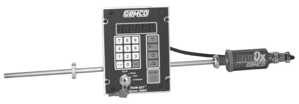
4 Chapter 1: General Description The standard 1996 Ram-Set consists of a transducer, transducer cable termination kit, controller, and output module. The transducer device is a magnetostrictive linear displacement transducer (LDT for short). The LDT consists of a fixed guide tube assembly attached to an electronics package, and a non-contacting magnet assembly that moves up and down the guide tube. The magnet position is precisely sensed by the guide tube electronics. The guide tube assembly is attached to a fixed member of the slide, typically at the Pitman arm. The magnet assembly is attached to a moving portion of the slide. The output signal of the LDT is transmitted through the cable termination kit. The kit consists of strain relief fittings at the transducer connection point, flexible cable between the transducer, and a J box mounted on the crown of the press. The J box has quick disconnect fittings for the flexible cable and cable running to the controller. The controller and output modules accept slide position information from the LDT, programming information, and energize outputs to accurately position the slide to any customer selected die number. 1.1 Controller Features and Functions The controller is housed in an all metal case that can be panel mounted. The controller consists of a mother board, which contains all keypad interface components, a CPU board, and a power supply board. The Ram-Set controller is the brain of the Ram-Set system. It provides the operator interface and microprocessor to carry out all programmed directions. The following features are found on the Ram-Set faceplate: Display - A six (6) digit L.E.D. read-out will show current shut height position, programming details, and while in automatic operation the display will show shut height movement. Programming Keys - There are three sets of programming keys on the Ram-Set faceplate. The largest group contains numbers from 0-9 for entering programming data. A C/CE or clear key will remove any erroneous programming mistakes, and an ENT or enter key for entering programming data into the controller memory. The second group of keys contains a DIE # key used to enter customer selected die numbers into the Ram-Set memory. An F or function key is used as a precursor to let the Ram-Set controller know that new programming data is being entered. The key must be depressed before any programming function is entered. Jog up and Jog down keys are used to manually adjust the press shut height. The keyswitch must be in the Jog mode to enable the Jog up/jog down keys. The last key is the Stop key. This will automatically disable the drive relays when the system is in the automatic mode and a drive sequence has been initiated. Mode Select Keyswitch - This four (4) position keyswitch allows customer selection of several modes. Auto - This mode is used when the customer desires to drive to a new pre-programmed shut height. Prog - This is a program mode. In this mode calibration data and die number/shut height values can be entered. Jog - Jog mode enables the Jog up/jog down keys, allowing manual adjustment of the shut height. Standby - The standby key should be used while the press is in operation. It locks out all automatic and manual movement, as well as programming features.
5 Chapter 1: General Description Located on the rear of the unit is a (14) fourteen terminal connector which interfaces with the output module, provides the 115VAC input, and also provides four auxiliary outputs. A (6) six terminal connector for transducer input and a D9 connector for RS485 communication are also located on the rear of the unit. 1.2 Output Board Features and Functions The output board is the press/ram-set interface. It contains the relays used to connect to the press shut height controls. Up/Down Relays - These triple pole relays should be tied into the appropriate Ram-adjust motor starter. In-Position Relay - This relay will energize when the customer programmed shut height is achieved. The controller allows programming of a +/- value at which the in-position relay will stay energized. The output of this relay could be used for visual indication or as an interface to the press control alerting the user to possible slide drift. Run Relay - This relay energizes when the mode select keyswitch is positioned in the standby mode. The relay is usually tied into the same circuit as the existing press run-interlock switch. The objective is to let the press controls receive positive feedback that slide adjustment is no longer possible. The output module accepts 115VAC to operate the relays and provide an auxiliary 24VDC output. Terminals are provided for the 115VAC power input, an auxiliary input, relay inputs from the controller, and the relay outputs.
6 Chapter 2: Installation Instructions Introduction This section describes the installation and wiring of a standard Ram-Set controller, output module and transducer. Changes to these instructions should be made as necessary if special options and/or equipment are used. The controller and output module should be installed in an area free of water spray, corrosive gases, flying chips or other foreign matter. The operating temperature should be between 32 and 125 degrees Fahrenheit, with less than 95% relative humidity. 2.1 Mechanical Installation Mounting the Transducer The proper mounting of the Ram-Set transducer assembly is critical to ensure the systems accuracy. A universal transducer mounting and cable termination kit can be provided with each system. The kit contains all hardware needed to complete mounting. When designing your own LDT mounting brackets, see Drawing D D. Using existing press controls, jog ram up to its maximum up position. Bypass up safety limit switch if necessary. Refer to Drawing D D 1996 Ram-Set Transducer Installation for the following installation instructions. Mounting steps: 1. Brackets for both the transducer and magnet assembly should be fabricated at time of installation. The brackets should be slotted as shown in the transducer installation drawing. The transducer bracket should be mounted to a fixed member of the slide, and the magnet assembly bracket to a movable portion of the slide. If mounting to a round surface, use v-block construction on the brackets. It is important to note the following dimensional minimum requirements when designing the brackets: A. An 8 minimum clearance is required from the bottom of the crown to the top of the transducer mounting bracket (at the point of transducer connection), when the press is at top dead center. B. A minimum gap is needed between the top of the transducer mounting bracket and the top of the magnet assembly bracket. C. Make sure the transducer guide tube has clearance when the slide adjustment is fully down. D. A tolerance of.001 per foot must be held between the side of the magnet assembly bracket and an imaginary perpendicular line intersecting the guide tube. D. A tolerance of.001 per foot must be held between the side of the magnet assembly bracket and an imaginary perpendicular line intersecting the guide tube. E. Check all other points for possible obstructions. The brackets should be affixed to the press with 3/8-16 socket head cap screws. 2. Attach the taping plate for weld block anchor on or near the transducer mounting bracket. The mating half with elbow assembly will act as a strain relief for the transducer cable.
7 Chapter 2: Installation Instructions 3. Mount the supplied junction box to the crown of the press in an area free from obstruction. The flexible cable from the junction box runs through the elbow assembly to the transducer. Run conduit from the junction box to the controller. Note: Transducer wires only in this conduit. A maximum transducer cable length of 30 ft. is recommended. Consult factory on cable lengths greater than 30 ft. Mounting the Controller Note: Panel cutouts, mounting holes, and sizes for each component are shown in the rear of the 1996 catalog section (page 6). The controller should be mounted in the appropriate panel cutout and securely bolted into place using the (4) four 3/16 diameter mounting holes. The output module is normally mounted inside the same enclosure, but can be mounted up to 30 feet from the controller. A 8 foot cable is provided standard. It is always good design practice to mount the controller and output module in the enclosure as far away from the motor starters and control relays as possible to minimize the effects of electromagnetic interference (EMI). Interconnecting wiring also should be routed to minimize EMI coupling. Note: In instances where the Ram-Set is being mounted directly on the press, care should be taken to isolate the controller and output boards from shock load and vibration. 2.2 Electrical Installation Introduction The Ram-Set is designed for use in an industrial environment and incorporates extensive transient suppression circuitry. However, the same general installation rules should be followed that are used on all micro-processor based equipment. Incoming AC lines should be from a clean power source and lines carrying computer level signals should not be routed in the same conduit as high voltage, transient producing circuits like variable speed drives, welders or DC switching circuits. Installation Disconnect existing press controls and re-wire press control per Drawing E , 1996 Ram-Set General Wiring Diagram. Please note that the typical press control wiring shown on this diagram is general in nature and may be modified to accommodate each particular application. Attach the pre-wired plug on the transducer cable to the transducer. Connect the second set of plugs inside the junction box and lastly, connect the transducer cable end to the (6) six place connector on the rear of the controller. The AC line voltage, 115VAC 60HZ, should be connected to the appropriate terminals on the controller and output module. Complete and/or check the interface wiring between the controller and output module. Calibration 1. Mode Select: Insert the mode select key into the keyswitch and turn to the program mode. With power on, the following sequences should be followed: 2. Initialize: The initialization code clears the Ram-Set memory. The initialization code should be entered prior to calibration to eliminate possible unwanted data. After initialization, proceed as follows: F ENT
8 Chapter 2: Installation Instructions 3. This unit has been set up to work in inches or millimeters. The operator can select between working with inches (to 1/1000 of an inch) or millimeters (to 1/100 of a millimeter). Default is inch mode (1). F ENT 0 or 1 0 = Millimeter 1 = Inch When millimeter mode is selected, all programmable values are entered as millimeters except the wire speed. The wire speed is still entered in inches per microsecond (i.e. the wire speed printed on the transducer s can). This value will be converted into millimeters internally. The default and maximum values in the inch mode for the altered functions are: Function Number Description Default Value Range Position 0 to in 8 System offset in 0 to in 11 Slow-down entry point in 0 to in 12 Upper limit in 0 to in 13 Lower limit in 0 to in 18 Ram In Position window in 0 to in Any time the readout mode is changed, some of the system s parameters will be reset and all of the die will be cleared to reflect the new mode. The default and maximum values in the millimeter mode for the altered functions are: The default and maximum values in the millimeter mode for the altered functions are: Function Number Description Default Value Range Position 0 to mm 8 System offset mm 0 to mm 11 Slow-down entry point 1.27 mm 0 to 7.00 mm 12 Upper limit mm 0 to mm 13 Lower limit 0.00 mm 0 to mm 18 Ram In Position window mm 0 to 3.00 mm 4. Wire Speed: Enter the transducer wire speed. The wire speed number can be obtained from the transducer data plate. Because each transducer has its own unique wire speed, it is imperative the proper wire speed is entered. Incorrect wire speed data will affect the system s accuracy. F ENT - Wire Speed # - ENT 5. Count Direction: Establish proper count direction. The standard mounting position of the transducer is with the rod end down. The top end of the transducer then indicates the upper-most position of the press slide. In cases where inverted counting may be desired, proceed as follows: (otherwise skip step) F ENT 0 or 1 ENT 0 = decreasing value from top to bottom (standard) 1 = increasing value from top to bottom (inverted)
9 6. Press Type: Select the type of press: (if applicable) Chapter 2: Installation Instructions F ENT 0, 1 or 2 ENT 0 = single action (standard) 1 = double action (inner slide) 2 = double action (outer slide) Note: If option 1 or 2 is picked, the 110VAC from the slide gap switch must be connected to Ram-Set per Wiring Diagram E C. 7. Offset: With keyswitch in program position, depress jog-up key. Jog past the upper mechanical overtravel limit to the upper maximum mechanical position. Determine this value (measure or use press manufacturers data) and enter value into Ram-Set offset. This will assure a consistent measurement format even when changes are made. F ENT - Max. Value - ENT Note: Please also note that offset can be set any known slide position. 8. Upper Limit: The electronic limits of the Ram-Set should be used in conjunction with the existing press mechanical overtravel limits. To set the upper electronic limit, jog the slide down past then back to the existing slide upper limit switch. Read the Ram-Set display and program this value as the electronic upper limit setting. F ENT - Value - ENT 9. Lower Limit: Jog slide to existing press mounted lower limit switch. Read the Ram- Set display and program this value as the Ram-Set lower electronic limit setting. F Value - ENT 10. Slow Dwell: The slow dwell settings are the method the Ram-Set uses to precisely position the slide. These time based dwells (on/off) are attached to the up/down output relays, and are enabled in the auto mode when the slide enters the slow down zone. The amount of time the on/off dwells should be enabled varies from system to system, but the idea is to enable the on dwell long enough to energize the slide adjust motor starter, and the off dwell long enough for the slide to coast to a stop. Slow dwell can be programmed from.01 to 9.99 seconds. A good typical value for the time on a dwell is.40 seconds. F ENT - Time On # - ENT Program time off for slow dwell. This function, more than any other, determines the repeatability of the automatic positioning. It is typically set at.60 seconds. F ENT - Time Off # - ENT 11. Slow Down Setpoint: Set the deceleration distance or slow down entry point. This is the point at which the system will begin to pulse the output to the Ram adjust motor starters. It is designed such that the system will drive toward the setpoint from below in all cases. If the ram is above the setpoint, the system will drive below the setpoint by the width of the down setpoint, stop for 3 seconds, and drive up to the programmed shut height. This method serves two purposes: one, to take the backlash out of the ram adjust system; and two, to gain consistency in adjustment by driving at the setpoint in one direction at all times. F ENT - Value - ENT
10 Chapter 2: Installation Instructions 12. Drift Window: Establish an acceptable drift window. If the slide moves outside of this window, the In Position relay denergizes. Typically to inch. F ENT - Value - ENT Note: In any cases where F ENT is used, steps one (1) through eleven (11) will be erased from memory and will have to be repeated. The calibration steps are now completed and the system is ready for programming. Chapter 3: Programming and Operating Instructions Programming Dies: 1. Programming New Die # s and Shut Height Values: A. Select Prog mode on keyswitch B. Depress F ENT C. Depress DIE # - Die code # - ENT D. Enter shut height and depress ENT E. *Optional Counter Balance Entry Enter counter balance value (1-16) and depress ENT The counter balance value will generate a (4) four binary output from the rear of the Ram-Set proportional to the programmed value. The binary output will interface to Gemco Series 2200 to automatically adjust the press counter balance. Note: It is important that shut height value entered has been pre-tested with die in press prior to entry. To program new die # s and shut heights at this point, simply start at step C. 2. Operating in Auto Mode: This function allows the retrieval of existing programmed dies and their associated shut heights. A. Keyswitch in auto mode. B. Depress DIE # - Die code # - ENT. The programmed optional counter balance will now appear on the display for 3 seconds then it will display the shut height value. C. Verify that shut height value and counter balance value correspond to the selected die. D. Depress ENT. This will enable the drive sequence. The drive sequence will remain active until the shut height drive mechanism moves the slide to the programmed value. E. Select Standby mode on keyswitch. The auto adjust sequence is now complete. 3. Operating in Jog Mode: This function allows the customer to manually jog the slide using the Ram-Set keys. A. Keyswitch in job mode. B. Depress appropriate Jog up or Jog down key on unit for appropriate motion.
11 4. Clear All Die # s and Positions: This function lets you clear all die numbers and shut height values without affecting the other functions. Simply select PROG mode and depress: F ENT. This will remove all die numbers and position values. 5. Remove a Specific Die # and Position: To remove a specific die, select PROG mode and depress: F ENT - DIE # - SPECIFIC DIE # - ENT. The specific die selected and associated shut height value are now deleted. 6. Review All Programmed Dies and Positions: This is a read-only function. It provides a review of all existing programmed die numbers *optional counter balance values and position values. In any mode depress: F ENT. The lowest die number will appear in the display followed by it s optional counter balance value then by it s corresponding position. By pressing ENT the remaining die(s), optional counter balance(s) and shut height(s) will be displayed in numerically increasing order. 7. Ram In Position Window: This function puts an In Position window around each selected die position. It compensates for small positional variations due to shock, temperature, etc. To use this function, select PROG mode and depress: F ENT - WINDOW ± VALUE - ENT. When in the AUTO mode the Ram will move to the center of the window before stopping. 8. Jogging with System Errors: Should the transducer and/or cable become disabled, or it is desired to move the ram beyond it s electronic limits this function allows the JOG keys to operate the slide in the manual mode. To access select JOG mode and depress: F ENT. The manual jog keys will now activate the slide motors even though the display may not be providing position feedback or the ram may be beyond it s limits. Note: Extreme care must be taken when operating in this mode. This mode will be reset when the selector switch is rotated out of the jog mode. 9. Counter Balance Override: Function #200 was added to allow for a counter balance override value. The counter balance override value, once programmed in the PROG mode, is implemented instantly. Once a new die has been selected in the AUTO mode, the new die s programmed counter balance value is implemented. The current counter balance value can be viewed through Function #200 in any mode. Example: In PROG mode: enter the override counter balance value in Function #200 as 2. <F> <2> <0> <0> <ENT> <2> <ENT> enter die #1 s position at and set the counter balance to 10. <F> <1> <ENT> <DIE #> <1> <ENT> <4> <2> <0> <0> <0> <ENT> <1> <0> <ENT> In AUTO mode: enter a die number. <DIE #> <1> <ENT> <ENT> Chapter 3: Programming and Operating Instructions
12 Chapter 3: Programming and Operating Instructions Once the die number is selected and <ENT> has been depressed, the preprogrammed counter balance value and shut height value for that die # will be displayed to be verified. Depressing <ENT> again will confirm and enable a drive to the selected shut height and the counter balance for that die will be implemented. Upon system initialization, the counter balance override value is set to zero. If power is shut down, once power is restored, the last counter balance utilized before shut down is implemented and displayed. 3.1 RS485 Protocol and Interface The RS485 option provides the user with the mechanism to establish a communication link between the 1996 Ram-Set and any remote system incorporating RS485 capability. The remote system could be a programmable controller, or any computer based operating system. Through use of this communication link, all Ram-Set functions can be monitored or changed. Up to 32 systems, including the host computer can be tied into this link. System Protocol The Ram-Set is factory set for 9600 baud rate, 8 bit word length, 1 stop bit, parity off, and parity even. To change baud rate: F ENT - Value - ENT The following baud rates are available: 150, 300, 600, 1200, 2400, 4800, or The remaining protocol information is entered by: F ENT - Value - ENT The value is a (4) four digit code relating to parity odd/even, parity enable/disable, bit data, transmit with or without leading zeros omitted. X X X X 0 = even parity, 1 = odd parity 0 = disable parity, 1 = enable parity 7 = seven bit data, 8 = eight bit data 0, 1 and 2 transmits 4, 5, 6 characters with leading zeros omitted 4, 5 and 6 transmits 4, 5, 6 characters without leading zeros omitted Each Ram-Set must have it s own unique address location from 00 to 99. F Value - ENT The host computer (bus master) must have an address on the same format as the Ram-Set. Program by: F Value - ENT Note: The address functions are only accessible through the keypad. (F-232, 233, 234, 235). Serial programming follows the keypad entry format.
13 Chapter 3: Programming and Operating Instructions Example: To enter die number 1 and shut height of : STXZmmF1ED1E0000EEOT. To access data through the serial port, the ENQ ($05) character must proceed entries. Example: STXZmmENQF1ED1EEOT would cause the Ram-Set to return STXZbbACKF001D001 : 10000EOT. If commands are strung together in the same transmission, ENQ must precede each function that data is being requested from: Command Symbols D ($44) Represents the die # key E ($45) Represents the ENT key F ($46) Represents the F key K ($4B) Used to request a program dump L ($4C) Used to request a decimal position P ($50) Used to request a transducer position : ($3A) Precedes returned function data = ($3D) Requested data is unavailable After the Ram-Set has successfully received a message, it will transmit the following: A. If no data was requested and no data errors occurred, it will transmit STXZmmACKEOT where mm is the last address. B. If data was requested, it will transmit STXZmm ACK (requested data) EOT. C. If an error occurred, it will transmit STXZmmNAK00xEOT. The x in the above transmission represents an error code. The codes are detailed below: Error Codes 1: Transmission error, over-run, framing or parity error 2: Receiver buffer overflowed (256 characters max.) 3: Data format error (check control characters) 4: Data error (check data limits) 5: Signal error (function 8 offset can t be entered) Pinout of D9 to any RS485 terminal Host D9 Ram-Set D GND Data Data Data Data
14 Chapter 4: Maintenance and Trouble Shooting The following procedures are intended as an aid to isolate system malfunctions down to field replaceable elements. These elements include; controller, output module, transducer and interconnecting wiring. Preliminary Checks Check System connections at the transducer, junction box, controller and output module to ensure that all connectors and wires are secure. A slight tug on each wire at the controller is recommended. Verify that all wiring to the controller and output board is in agreement with the data plates. Check input power to the controller and output board. Input voltage should be from 105 to 125VAC. Verify line fuse on output board has not blown. Malfunction Analysis Problem: Unit powers up with EE POS Cause: There are several probably causes for this error message. To check system for cause, depress F ENT. This causes the unit to display a trouble flag, shown below: EE0001 = Signal loss EE0010 = Lower limit exceeded EE0100 = Upper limit exceeded EE1000 = Slide gap interference fault or loss of 110 V.A.C. on slide gap interference input. EE0000 = All are correct Note: If more than one error exists, a combined error message will be displayed. Ex.: a slide gap interference fault and lower limit exceeded fault occur at the same time, an error flag of EE1010 shows. To trouble shoot flags: 1. EE Shows that a transducer signal loss has occurred. Check all transducer connections. If all connections are made, check circuit integrity (see transducer information sheet). 2. EE Lower limit exceeded. The electronic lower limit has been exceeded. Putting the keyswitch in the Jog Mode and moving the slide out of this zone (jog up) will reset this fault. 3. EE Upper limit exceeded. The electronic upper limit has been exceeded. Putting the keyswitch in the Job Mode and moving the slide out of this zone (jog down) will reset this fault. 4. EE The slide gap interference switch has been activated. Depending on which slide is being monitored, a jog move will have to be made to bring slide out of the slide gap interference zone. Or 110 V.A.C. has been lost on slide gap interference switch when F ENT is set for option 1 or 2. Problem: Unit reads EEEEEE Cause: This is due to a programming error. Depress the clear (C/CE) key. Now reprocess sequence. If EEEEEE s persist, check diagnostic code.
15
16 Chapter 4: Maintenance and Trouble Shooting Problem: Outputs will not operate or continuously stay on. Cause: Output interface wire(s) disconnected, output driver blown, CPU problem or blown fuse on output module. Check all wire connections and output fuse. If check out proceed as follows: A. To check up and down relays put keyswitch in jog mode. With a digital volt meter check between GND and up/down terminals on output board. There should be a presence of 25 to 28VDC across these terminals. Depress the up/down button of keypad, the output voltage should drop to around.7vdc. If no voltage is present across GND and up/down terminals, the driver outputs from the controller are blown or an internal processor error has occurred. B. To check run contact put keyswitch in stand-by mode. Check voltage across GND and run terminals on output board. (See (A) for cause of errors). C. To check in position contact put keyswitch in stand-by mode. Depress the die # key (which will display last used die number and shut height), jog system to this shut height. The in position, L.E.D. on keypad will light. Now check voltage between GND and in position terminal on output board. (See (A) for cause of error). Problem: Cause: Problem: Cause: Problem: Ram-Set controller display blank and outputs not operating. Fuse blown inside Ram-Set controller. Remove back plate and examine fuse on power supply board. Controller displays meaningless data. Outputs may or may not operate properly. Controller mounted in a high shock and/or vibration environment causing intermittent connections. Controller operating in a high electrical noise environment. Cause: Improperly connected cable shield or high power AC wiring running in same conduit with transducer cable. It is always a good practice to isolate programmer wiring from other machines.
17 Chapter 4: Maintenance and Trouble Shooting Note: Malfunctions due to the above can usually be cleared by removing, and then reconnecting power to the controller. The cause of such problems can be determined and eliminated. If removal and reconnection of power does not correct the problem, a controller failure has occurred. If the outputs are operating properly, the failure is most likely in the display section. If outputs do not operate properly, the failure is most likely in the CPU section. Chapter 5: Programming and Function Charts Password Function Initialization Number Description Value Range 1 Program new die # s and positions N/A Up to 5 digits 753 Clear all die # s and positions N/A N/A 8 System offset 48 In. Max. Pos. 0 to inch 9 Transducer calibration (wire speed) in/sec to in/sec. 10 Up/down counting direction 0 (Up) 0=Up; 1=Down 11 Slow-down entry point inch 0 to.259 inch 12 Upper limit inch 0 to inch 13 Lower limit inch 0 to inch 14 Time-on for slow dwell 0.40 sec. 0 to 9.99 second 15 Time-off for slow dwell 0.40 sec. 0 to 9.99 second 16 Trouble flags N/A N/A 17 Review all programmed dies & positions N/A N/A 18 Ram In Position window.010 inch 0- to.099 inch 19 Software number N/A N/A 21 Inches/mm 1 0 or Remove a specific die # and position N/A N/A 200 Counter balance override 0 0 to Diagnostics (Function #268) N/A N/A 391 Initialization N/A N/A 555 Jogging with system errors (Function #555) N/A N/A Note: If an attempt is made to enter too large a value, the display will show EEEEE4. If this value is too small, the display will show EEEEE3. Example: Entering a ram position outside of the upper and lower limits.


18 1080 North Crooks Road Clawson, MI M1R 03/02 Z150 5C
955S BRIK. Series 955S Brik. Smart BRIK LDT ABSOLUTE PROCESS CONTROL KNOW WHERE YOU ARE... REGARDLESS. Linear Displacement Transducer
 Series 955S Brik Linear Displacement Transducer Installation Manual 955S BRIK Smart BRIK LDT ABSOLUTE PROCESS CONTROL KNOW WHERE YOU ARE... REGARDLESS Introduction The 955S Smart Brik is an accurate programmable,
GEMCO. Installation & Programming Manual. Series 1746R. PLC Resolver Interface Module. For Allen-Bradley SLC 500 I/O Chassis
 Series 746R GEMCO PLC Resolver Interface Module Installation & Programming Manual For Allen-Bradley SLC 500 I/O Chassis Spec Tech Industrial 03 Vest Ave. Valley Park, MO 63088 Phone: 888 SPECTECH E-mail:
955 ebrik INSTALLATION MANUAL. Series ebrik ABSOLUTE PROCESS CONTROL KNOW WHERE YOU ARE... REGARDLESS LINEAR DISPLACEMENT TRANSDUCERS
 Series ebrik INSTALLATION MANUAL LINEAR DISPLACEMENT TRANSDUCERS ABSOLUTE PROCESS CONTROL KNOW WHERE YOU ARE... REGARDLESS Introduction The is an accurate programmable, auto-tuning, noncontact, linear
TIME SENTRY MANUAL PROGRAMMABLE LIMIT SWITCH SERIES RC95BPS
 TIME SENTRY MANUAL PROGRAMMABLE LIMIT SWITCH SERIES RC95BPS TABLE OF CONTENTS I INTRODUCTION / DESCRIPTION II INSTALLATION III PROGRAMMING IV EXPANSION MODULES V FAULT CHECK VI SECURITY INPUTS VII REMOTE
Product Manual 8330GMX
 Product Manual 8330GMX Register Access Panel with Modbus Interface Quartech Corporation 15923 Angelo Drive Macomb Township, Michigan 48042-4050 Phone: (586) 781-0373 FAX: (586) 781-0378 Email: Sales@QuartechCorp.com
GEMCO. Installation & Programming Manual. Series 1746L. PLC LDT Interface Module. For Allen-Bradley SLC 500 I/O Chassis
 Series 746L GEMCO PLC LDT Interface Module For Allen-Bradley SLC 5 I/O Chassis Spec Tech Industrial 3 Vest Ave. Valley Park, MO 6388 Phone: 888 SPECTECH E-mail: sales@spectechind.com www.spectechind.com
This Datasheet for the IC697CHS790. Rack, 9 Slots, Rear Mount.
 This Datasheet for the IC697CHS790 Rack, 9 Slots, Rear Mount. http://www.cimtecautomation.com/parts/p-14771-ic697chs790.aspx Provides the wiring diagrams and installation guidelines for this GE Series
Tachometer Panel, PE3
 Features Plug-n-play units with factory programmed parameters 4-20 ma feedback signal Isolated relay alarm outputs Frequency input Diagnostic indicators NEMA 4 Enclosure Model PE3, Tachometer Panel Benefits
Series 957SSI Brik. Linear Displacement Transducer. Installation Manual. 957SSI Brik ABSOLUTE PROCESS CONTROL KNOW WHERE YOU ARE...
 Series 957SSI Brik Linear Displacement Transducer Installation Manual 957SSI Brik ABSOLUTE PROCESS CONTROL KNOW WHERE YOU ARE... REGARDLESS Contents Chapter 1: Overview... 2 Chapter 2: Installing... 5
Allen-Bradley PLCs. 100 Programmable Controller Processor Unit -Catalog Nos LPI01, -LP102, -LP103, -LP104 SLC TM. The Unit
 PRODUCT DATA SLC TM 100 Programmable Controller Processor Unit -Catalog Nos. 1745-LPI01, -LP102, -LP103, -LP104 The SLC 100 programmab/e Contro"er The SLC 100 Programmable Controller is easy to program,
PLC Racks IC697CHS782/783
 5 1 PLC Racks IC697CHS782/783 (IC697CHS782/783) datasheet Features Accepts 3rd Party VME modules which require 0.8 spacing. Accepts all IC697 PLC module types. Rear mount rack mounts in a 10 (254 mm) deep
TOXALERT MODEL AIR 2000
 TOXALERT MODEL AIR 2000 NOTE: Toxalert s Model GVU-CO 2 Sensor is the same as the Air2000R. Microprocessor-based, Infrared Environmental CO 2 Sensor OPERATOR S MANUAL TOXALERT TM INTERNATIONAL INC. P.O.
Instruction Manual. M Pump Motor Controller. For file reference, please record the following data:
 Instruction Manual M Pump Motor Controller For file reference, please record the following data: Model No: Serial No: Installation Date: Installation Location: When ordering replacement parts for your
mbc082 Bus Converter
 BUS CONVERTER RS485 TO 1-WIRE BUS mbc082 mbc082 Bus Converter Document. 10910, Revision - February 2007 2007 CMC Industrial Electronics Ltd. This page intentionally left blank. mbc082 Bus Converter Technical
Model HM-535 Power Supply Installation and Service Instructions
 Model HM-535 Power Supply Installation and Service Instructions 430-535 0104 2004 Heritage MedCall, Inc SENTRY INSTALLATION & SERVICE INSTRUCTIONS POWER SUPPLY UNIT Model HM-535 IMPORTANT SAFETY INSTRUCTIONS
Standard Options. Model 4100 Position Indicating Meter. Three Phase Motor Control. Positran Transmitter
 Standard Options Model 4100 Position Indicating Meter A percent-of-full-travel meter is supplied with a trim potentiometer resistor, terminal block and connectors. A potentiometer is required in the actuator
INSTRUCTION MANUAL STATION CONTROLLER SC1000 MOTOR PROTECTION ELECTRONICS, INC.
 INSTRUCTION MANUAL STATION CONTROLLER SC1000 MOTOR PROTECTION ELECTRONICS, INC. 2464 Vulcan Road, Apopka, Florida 32703 Phone: (407) 299-3825 Fax: (407) 294-9435 Revision Date: 9-11-08 Applications: Simplex,
H704-42(H)(E), H704-42/1(H)(E)
(E), H704-42/1(H)(E)") POWER MONITORING INSTALLATION GUIDE H704-42(H)(E), H704-42/1(H)(E) Branch Current Monitor DANGER NOTICE Installer's Specifications General: Operating Temp. Range 0 to 60 C (32 to 140 F) (
POWER MONITORING INSTALLATION GUIDE H704-42(H)(E), H704-42/1(H)(E) Branch Current Monitor DANGER NOTICE Installer's Specifications General: Operating Temp. Range 0 to 60 C (32 to 140 F) (
Rexroth Controller Installation & Operations Manual
 Electric Drives and Controls Hydraulics Linear Motion and Assembly Technologies Pneumatics Service Rexroth - 105 Controller Installation & Operations Manual The Drive & Control Company Table of Contents:
MICRO SERIES PROCESS DISPLAYS LARGE DIGIT MODELS
 The MICRO SERIES PROCESS DISPLAYS LARGE DIGIT MODELS Mighty-5 DPM MODELS Micro-P & Mighty-1 Mighty-1 Micro-P ELECTRO-NUMERICS, INC. Introduction The Electro-Numerics family of Digital Panel Meters and
Installation and Operation Instructions I/CO 2, I/CO 2 -VDC, I/CO 2 -T
 Installation and Operation Instructions I/CO 2, I/CO 2 -VDC, I/CO 2 -T READ THESE INSTRUCTIONS BEFORE YOU BEGIN INSTALLATION LOCATION The I/CO 2 transmitter is designed to mount over a standard single
MODEL 8000MP LEVEL SENSOR
 1 MODEL 8000MP LEVEL SENSOR INSTRUCTIONS FOR INSTALLATION, OPERATION & MAINTENANCE VISIT OUR WEBSITE SIGMACONTROLS.COM 2 SERIES 8000MP LEVEL SENSOR 1. DESCRIPTION The Model 8000MP Submersible Level Sensor
Vorne Industries. 2000S Series Serial Input Alphanumeric Display User's Manual
 Vorne Industries 2000S Series Serial Input Alphanumeric Display User's Manual 1445 Industrial Drive Itasca, IL 60143-1849 Telephone (630) 875-3600 Telefax (630) 875-3609 2000S Series Serial Input Alphanumeric
Table of Contents 1. Overview Installation...6
 (2003-01-31) Table of Contents 1. Overview...1 1.1. Introduction... 1 1.2. Product Description... 1 1.2.1. Mechanical Actuator Assembly with M2CP Electrical Enclosure... 1 1.2.2. Variable Frequency Controller
Version Accurate Technology, Inc.
 Single Axis Position Control Unit (PCU) User s Manual Version 2.040 270 Rutledge Rd. Suite E Fletcher, North Carolina 28732 USA 828-654-7920 www.proscale.com The contents of this document are protected
GV3000/SE Operator Interface Module (OIM) User Guide Version 2.0 M/N 2RK3000
 User Guide Version 2.0 M/N 2RK3000") GV3000/SE Operator Interface Module (OIM) User Guide Version 2.0 M/N 2RK3000 Instruction Manual D2-3342-2 The information in this manual is subject to change without notice. Throughout this manual, the
GV3000/SE Operator Interface Module (OIM) User Guide Version 2.0 M/N 2RK3000 Instruction Manual D2-3342-2 The information in this manual is subject to change without notice. Throughout this manual, the
MAINTENANCE MANUAL. EDACS REDUNDANT POWER SUPPLY SYSTEM 350A1441P1 and P2 POWER MODULE CHASSIS 350A1441P3, P4, AND P5 POWER MODULES TABLE OF CONTENTS
 MAINTENANCE MANUAL EDACS REDUNDANT POWER SUPPLY SYSTEM 350A1441P1 and P2 POWER MODULE CHASSIS 350A1441P3, P4, AND P5 POWER MODULES TABLE OF CONTENTS SPECIFICATIONS*... 2 INTRODUCTION... 3 DESCRIPTION...
1/32-DIN TEMPERATURE CONTROLLER INSTALLATION, WIRING AND OPERATION MANUAL FORM 3882
 1/32-DIN TEMPERATURE CONTROLLER INSTALLATION, WIRING AND OPERATION MANUAL FORM 3882 This manual is intended for use in support of installation, commissioning and configuration of the 1/32-DIN Temperature
MOTION MASTER SENSOCONTROLLER - PRODUCT SPECIFICATION S MMS WA-5, SU-5, EXP-5 WA-5 SU-5 EXP-5
 MOTION MASTER SENSOCONTROLLER - PRODUCT SPECIFICATION S MMS WA-5, SU-5, EXP-5 VER5.2 WA-5 SU-5 EXP-5 GENERAL DESCRIPTION Belcatec Design Inc. designs and manufactures Motion Master Sensocontroller safety
SC2000 MOTOR PROTECTION ELECTRONICS, INC. INSTRUCTION MANUAL. (407) Phone: Website:
 Phone: Website:") SC2000 INSTRUCTION MANUAL MOTOR PROTECTION ELECTRONICS, INC. 2464 Vulcan Road Apopka, Florida 32703 Phone: Website: (407) 299-3825 www.mpelectronics.com Operating Program Revision: 12 Revision Date: 8-27-14
SC2000 INSTRUCTION MANUAL MOTOR PROTECTION ELECTRONICS, INC. 2464 Vulcan Road Apopka, Florida 32703 Phone: Website: (407) 299-3825 www.mpelectronics.com Operating Program Revision: 12 Revision Date: 8-27-14
Product Manual Pushbutton Station for Modicon Programmable Controller MODBUS Interface
 Product Manual 8652 Pushbutton Station for Modicon Programmable Controller MODBUS Interface Quartech Corporation 15923 Angelo Drive Macomb Township, Michigan 48042-4050 Phone: (586) 781-0373 FAX: (586)
I need to protect my equipment against damaging power surges and spikes.
 Complex Problems I need a fail safe way to distribute clean power to my system. I need to protect my equipment against damaging power surges and spikes. I need a way to both monitor my electrical system
Quick Start Installation Guide
 apc/l Quick Start Installation Guide Version A2 Document Part Number UM-201 May 2010 OVERVIEW The apc/l is an intelligent access control and alarm monitoring control panel which serves as a basic building
Instruction Manual. Electrical Management System (EMS) EMS-HW30C & EMS-HW50C
 EMS-HW30C & EMS-HW50C") Instruction Manual Electrical Management System (EMS) EMS-HW30C & EMS-HW50C EMS-HW50C EMS-HW30C! CAUTION These instructions are intended to provide assistance with the installation of this product, and
Instruction Manual Electrical Management System (EMS) EMS-HW30C & EMS-HW50C EMS-HW50C EMS-HW30C! CAUTION These instructions are intended to provide assistance with the installation of this product, and
A Axis M-Functions Level 1 A Axis Standard A Axis SMT Level 2. Each console includes the following:
 Hardware List The 3000M Crusader II Upgrade system has been custom configured to provide the necessary hardware required for installation on your machine. Verify that you have received all the correct
Energy Management System. Operation and Installation Manual
 Energy Management System Operation and Installation Manual AA Portable Power Corp 825 S 19 TH Street, Richmond, CA 94804 www.batteryspace.com Table of Contents 1 Introduction 3 2. Packing List 5 3. Specifications
E102 - Advanced Strain Gauge Transducer Display Interface. Contents
 E102 - Advanced Strain Gauge Transducer Display Interface Contents Torque Transducer Display Interface: TSE3249R Strain Gauge Transducer Display Interface [E102] Operating Guide: TSE2098V (Includes Introduction,
Nearus USB2.0 Camera Manual NU-350-USB2PTZ-B
 Nearus USB2.0 Camera Manual NU-350-USB2PTZ-B Safety Tips Please read this manual carefully before installing the camera. Keep the camera away from violent vibration, physical stress, moisture, extreme
EntraGuard Bronze. Quick Start Guide. Telephone Entry. 1.0 Specifications. 2.0 Unit Installation
 The EntraGuard Bronze is a residential telephone keypad entry system which allows a homeowner to communicate directly with visitors and provide access by using any phone extension in the home. Because
Data sheet MK 20 GR. Customized solution or off-the-shelf: The choice is yours!
 Data sheet MK 20 GR Customized solution or off-the-shelf: The choice is yours! MK20-GR data sheet Looking for a quick and reliable solution? Then rely on our standard products: Our universal controls provide
The PM1000 series is a universal 4 digit LED plug-on display for transmitters with 4-20mA 2 wire output and fitted with DIN43650 connector.
 PM1000 SERIES PLUG-ON DISPLAY BRIGHT LED DISPLAY INDICATION RANGE -999 TO +9999 FITS TO DIN 43650 CONNECTOR PLUG-ON TO ANY TRANSMITTER WITH 4-20MA OUTPUT EASY TO SCALE ON SITE ROBUST DESIGN SET POINT OPTION
TARA CONTROLS AGC-5. UCI Random Start USER S GUIDE. With Optional Warning Flashes for the Hearing Impaired. TARA CONTROLS by Cartessa Corporation
 TARA CONTROLS AGC-5 UCI Random Start USER S GUIDE With Optional Warning Flashes for the Hearing Impaired TARA CONTROLS by Cartessa Corporation 4825 Cincinnati-Brookville Road Shandon, Ohio 45063 Phone:
FLEX Ex Spring Clamp Terminal Base
 Installation Instructions FLEX Ex Spring Clamp Terminal Base (Cat. No. 1797-TB3S) 1 10 11 4 Only remove this cover plug if connecting another terminal base unit. 3 5 6 12 2 7 8 9 41253 Component Identification
Table of Contents
 Table of Contents Table of Contents Analog Input Module (12-Bit) Assembly cat. no. 1771-IF Series B and Analog Input Expander (12-Bit) cat. no. 1771-E1, -E2, -E3 are plug-in modules that interface analog
INSTRUCTION MANUAL FOR VAR/POWER FACTOR CONTROLLER SCP
 INSTRUCTION MANUAL FOR VAR/POWER FACTOR CONTROLLER SCP 250 Publication: 9 1100 00 99Y Revision: S 04/04 INTRODUCTION This instruction manual provides information about the operation and installation of
User Operation Manual: Motorized Valve Controller for Valved Sources
 User Operation Manual: Motorized Valve Controller for Valved Sources Table of Contents BEFORE YOU BEGIN...2 Safety Precautions...2 Product Concerns...2 Specifications...3 Support...3 INTRODUCTION...4 Product
PACSystems RX7i IC698CHS009/119
 January 2010 The RX7i rack can be used for all RX7i CPU and I/O configurations, Series 90-70 I/O, and VME modules. Backplane connectors are spaced on 0.8" (20.3mm) centers to accommodate single-width RX7i
Quantum III. Compact DC Drive Package. Slitter DC Drive Package. Quantum III
 Compact DC Drive Package The delivers a DC drive package that integrates the intelligence of the Mentor II with a space saving design that incorporates many accessories typically required in the North
Andover ContinuumTM Infinet II
 Andover ContinuumTM Infinet II The i80 Series controllers are designed for control of Air Handling Units, Roof Top Units, and other mechanical plant equipment. Features 0 Choose the i80 model with the
DUAL LOOP DETECTOR WITH MODBUS COMMUNICATIONS
 LD220 DUAL LOOP DETECTOR WITH MODBUS COMMUNICATIONS USER MANUAL P.O.Box 24 STANFIELD 3613 SOUTH AFRICA Tel: +27 (031) 7028033 Fax: +27 (031) 7028041 Email: proconel@proconel.com Web: www.proconel.com 18/08/2005
PMDX-105. I/O Option Riser Board User s Manual. Document Revision: 1.1 Date: 7 September 2004 PCB Revision: PCB-443A
 PMDX-105 I/O Option Riser Board User s Manual Date: 7 September 2004 PMDX Web: http://www.pmdx.com 7432 Alban Station Blvd., A105 Phone: +1 (703) 912-4991 Springfield, VA 22150-2321 USA FAX: +1 (703) 912-5849
SED2 Variable Frequency Drives with Electronic (E) Bypass Options
 Bypass Options") SED2 Variable Frequency Drives with Electronic (E) Options Description The E- Options are companion packages for the family of SED2 Variable Frequency Drives (s). For information on the family of SED2
SED2 Variable Frequency Drives with Electronic (E) Options Description The E- Options are companion packages for the family of SED2 Variable Frequency Drives (s). For information on the family of SED2
egate Product Catalog Electronic activegate Control Stabilize your Process
 Product Catalog Electronic activegate Control Stabilize your Process CAT-16-0013_EN-Rev06 EN 05/2017 Electric Valve Gate Product Description Hot Runner System Patented electronically actuated Valve Gate
Unitary Controller. Features. Description. Technical Specification Sheet Rev. 6, March, 2000
 Technical Specification Sheet Rev. 6, March, 2000 Unitary Controller The Unitary Controller can operate as an independent stand-alone controller, or can be connected to the APOGEE Automation System via
PROSMART Parts and Services Catalog
 Parts and Services Catalog TABLE OF CONTENTS CM s & DM s Communication Module Options 3 Data Monitoring Options 4 Sensors & Cables Vibration/Temperature Sensor Options 5 Mounting Adapter for Vibration/Temperature
INSTALLATION DKM-409 NETWORK ANALYSER WITH HARMONIC MEASUREMENT AND SCOPEMETER. Before installation:
 DKM-409 NETWORK ANALYSER WITH HARMONIC MEASUREMENT AND SCOPEMETER The DKM-409 is a precision instrument designed for displaying various AC parameters in 3-phase distribution panels. Thanks to its isolated
Installing the Cisco AS5400XM Universal Gateway
 CHAPTER 3 Installing the Cisco AS5400XM Universal Gateway This chapter guides you through the installation of the Cisco AS5400XM universal gateway and includes the following sections: Setting Up the Chassis,
Models VSP12824V & VSP12860V
 Programmable Voltage Interface Unit Models VSP12824V & VSP12860V Installation & Programming Manual PREFACE Important Installation Information It is the purchasers responsibility to determine the suitability
Resolver to Digital Expansion Board
 Resolver to Digital Expansion Board Catalog No. EXB009A01 Installation and Operating Manual 6/98 MN1313 Table of Contents Section 1 General Information............................. 1-1 Introduction....................................
MT400 MOTION CONTROLLER
 MT400 MOTION CONTROLLER INSTALLATION & TECHNICAL MANUAL 5/30/2012 417 Wards Corner Road Loveland, OH 45140 800.659.8250 FAX: 513.398.2536 www.maxitronic.com Table of Contents Page 3: Page 4: Page 5: Page
DSTHM-2 COMBINED T AND RH DUCT TRANSMITTER. Mounting and operating instructions
 Mounting and operating instructions Table of contents SAFETY AND PRECAUTIONS 3 PRODUCT DESCRIPTION 4 ARTICLE CODES 4 INTENDED AREA OF USE 4 TECHNICAL DATA 4 STANDARDS 4 OPERATIONAL DIAGRAMS 5 WIRING AND
Model User Manual Revision E 04/29/99. OEM Gaging System. Part Number R01
 04/29/99 Model 3800 OEM Gaging System User Manual Revision E Part Number 028585-R01 Information in this document is subject to change without notice. No part of this document may be reproduced or transmitted
TECHNICAL DATASHEET #TDAX023240
 Preliminary TECHNICAL DATASHEET #TDAX023240 2 Quadrature Decoder Inputs, Dual Valve Controller 2 Quadrature Decoder Inputs 2-3A Outputs CAN (SAE J1939) Configurable with Electronic Assistant P/N: AX023240
DirectCommand Installation 5 Channel Spreader Control Module Technology
 DirectCommand Installation Ag Leader Technology Note: Indented items indicate parts included in an assembly listed above Part Name/Description Part Number Quantity Direct Command Kit 4100582 1 Cable Installation
Trident and Trident X2 Digital Process and Temperature Panel Meter
 Sign In New User ISO 9001:2008 Certified Quality System Home Products Online Tools Videos Downloads About Us Store Contact Policies Trident and Trident X2 Digital Process and Temperature Panel Meter Products
Sidewinder Pumps Inc. AC C1D2 Timer/Controller
 Sidewinder Pumps Inc. AC C1D2 Timer/Controller Page 1 of 14 Rev 4/26/17 Table of Contents 1. Warnings --------------------------------------------------------------------------------------------------
Level-Lance Model 5400A
 Sales Manual Section 100 PRODUCT SPECIFICATION 5400A GENERAL DESCRIPTION The ROBERTSHAW Level-Lance Model 5400A is a microprocessor based, multi-point On-Off capacitance type level detection system. Utilizing
Carbon Monoxide Sensor - ModBus
 Introduction The CO Sensor uses an electrochemical sensor to monitor CO level in a range of 0 to 500 ppm and communicates via an RS-485 network configured for ModBus protocol. Before Installation Read
Repair and Replacement Instructions Genesis Desking Lift System
 Field Service Guide for Lift System Components Controllers, Motors, Cables and Switches Repair and Replacement Instructions KI-62057R1/PDF/309 Used with written consent. Copyright, Suspa Inc., 2002 Before
Residential/Light Commercial Remote Control System
 MODULAR CONTROLLER REMOTE CONTROL Residential/Light Commercial Remote Control System OWNER S MANUAL AND INSTALLATION INSTRUCTIONS CONTENTS INTRODUCTION 2 SYSTEM COMPONENTS - REMOTE 3 SYSTEM COMPONENTS
C-Series C142 Machine Controller Eurocard DIN Packaged Systems
 C-Series C142 Machine Controller Eurocard DIN Packaged Systems FEATURES: Available as 2- or 3-axes CNC Controller Remote START/STOP/RESET Bidirectional serial communication at up to 192 baud 32K of on-board
2. Actuator B: Ball type P: Pin type F: Flat type
 Contact Displacement Sensor Built-in Amplifier Ensures Ease of Use and Saves Wiring Effort. Sensor Operates with a Low Force in a Wide Range of Applications. H Works with a low operating force (30 gf)
Uninterruptible Power Supplies
 Xi Series 1-6kVA True On-Line UPS Features Rack-Mount/Standalone Format Universal Battery Design (Optional 10 year batteries) Dual Mains Input Dual Position Backlit LCD LCD Load Segment Control 2.5kVA
SMARTEYE P-Linc User Manual VERSION L1.5 Revision 4
 SMARTEYE P-Linc User Manual VERSION L1.5 Revision 4 www.smarteyecorporation.com related documents: SMARTEYE Electronics Assembly User Manual SMARTEYE Twin User Manual The material in this manual is for
Switching Power Supply
 Switching Power Supply Highly Reliable and Full-functioned 1-year Life Expectancy, 12, 1, or 24 V output voltages, and 30, 60, 0, or 10 W power ratings. 8 to 132 VAC or 170 to 264 VAC switchable input
PowerFlex 400 AC Drive Guide Specification
 PowerFlex 400 AC Drive Guide Specification Adjustable Frequency Drives with Bypass 3.0 50HP @ 208V AC 3.0 350HP @ 480V AC PART 1 GENERAL 1.01 Quality Assurance A. The manufacturer shall have minimum 5
EPS 06 in rear housing type A1
 Field Installation and / or Replacement of RACO Electronic Position Sensor Board EPS 02 & EPS 06 - Electronic Limit Switches - Analog Output Position Signal - Very Accurate - Easy To Use - Robust - Dependable
- Electronic Limit Switches - Very Accurate - Easy to use - Robust - Dependable - High Resolution - Non Contact Measurement - Wide Temp.
 1-30-2018 EPS 02 Operating Instructions RACO Electronic Position Sensor - Electronic Limit Switches - Very Accurate - Easy to use - Robust - Dependable - High Resolution - Non Contact Measurement - Wide
Series P215DP Single/Dual Pressure Input Condenser Fan Speed Controllers For Single Phase Motors (incl. built-in RFI suppression filter)
") PSC 0108 European Refrigeration Controls Catalogue Catalog Section 4 Product Bulletin Series Single/Dual Pressure Input Condenser Fan Speed Controllers For Single Phase Motors (incl. built-in RFI suppression
PSC 0108 European Refrigeration Controls Catalogue Catalog Section 4 Product Bulletin Series Single/Dual Pressure Input Condenser Fan Speed Controllers For Single Phase Motors (incl. built-in RFI suppression
MTII4200 Level Transmitter Installation, Operation & Maintenance Instructions
 Specialists in Liquid Level Indication MTII4200 Level Transmitter Installation, Operation & Maintenance Instructions Section: M500 Bulletin: M500.31 Date: 05-17-16 Supersedes: 09-30-11 1. INTRODUCTION
FOR PC BOARD TO FLAT CABLE
 AXM FOR PC BOARD TO FLAT CABLE MIL CONNECTORS (AXM) Density mounting Long lever type Short lever type Compliance with RoHS Directive FEATURES 1. High density mounting is possible. Even with mounting right
BACnet. b3810 Series Local Controllers
 BACnet b380 Series Local Controllers The Andover Continuum TM b380 series controllers are designed for control of Air Handling Units, Roof Top Units, and other mechanical plant equipment. 0 Features Choose
Ag Leader Technology Insight. Direct Command Installation Spra-Coupe 7000 Series
 Note: Indented items indicate parts included in an assembly listed above. Part Name / Description Part Number Quantity Direct Command Spra-Coupe 7000 Kit 4100531 1 Liquid Product Control Module 4000394
CS 140RC. Joystick Controller Configuration and Set-up Manual
 CS 140RC Joystick Controller Configuration and Set-up Manual 2/17 Table of Contents 1 Installation Recommendations 4 1.1 Step 1 4 1.2 Step 2 4 2 CS-140 Module Descriptions 6 2.1 Armrest Module 6 2.2 Joystick
MRC 7000 Proven Recording Reliability that Became the Industry Standard!
 Data Sheet Recorder//Profiler DESCRIPTION The MRC7000 Recorder/ is a microprocessor based circular chart instrument capable of measuring, displaying, recording and controlling up to two process variables
RS3000 SERIES BILL ACCEPTORS
 Flash Diagnostic Codes RS3000 SERIES BILL ACCEPTORS INSTALLATION GUIDE s of the bill acceptor. Below is a chart that lists all the flash codes of the RS3000 Bill Acceptor and a description of each code.
Voltage Dip-Proofing Inverter
 Voltage Dip-Proofing Inverter DPI54S / 54L Series Models 120V & 208/230 50/60Hz Contents: Introduction...3 Theory of operation...3 Specifications...5 Up-time considerations...6 Installation Guide...7 Test
M-5072 Retrofit Kit For M-4272 Digital Motor Bus Transfer System
 SYNCHRONIZING M-5072 Retrofit Kit For M-4272 Digital Motor Bus Transfer System Adapts M-4272 Digital Motor Bus Transfer System as a replacement for existing analog motor bus transfer equipment Provides
AD-8923-BCD. Remote Controller (BCD) INSTRUCTION MANUAL 1WMPD
 INSTRUCTION MANUAL 1WMPD") AD-8923-BCD Remote Controller (BCD) INSTRUCTION MANUAL 1WMPD4002137 2010 A&D Company, Limited. All rights reserved. No part of this publication may be reproduced, transmitted, transcribed, or translated
AD-8923-BCD Remote Controller (BCD) INSTRUCTION MANUAL 1WMPD4002137 2010 A&D Company, Limited. All rights reserved. No part of this publication may be reproduced, transmitted, transcribed, or translated
T E M P O S O N I C S I I I INSTALLATION CAUTION! B. CONNECTORS RG Connector. D6 Connector: INTEGRAL CABLE P Integral Cable
 T E M P O S O N I C S I I I INSTALLATION C A N B U S O U T P U T 550573 B W I R I N G - C A N b u s O U T P U T S CONNECTORS RG Connector Pin No. Wire Color Function 1 Gray CAN-L 2 Pink CAN-H 3 Yellow
MODEL SW6000 & SM6100 CENELEC INSTRUCTIONS
 MODEL SW6000 & SM6100 CENELEC INSTRUCTIONS Installation Manual 1180 METRIX Experience Value 8824 Fallbrook Dr. Houston, TX 77064, USA Tel: 1-281-940-1802 After Hours Technical Assistance: 1-713-702-8805
Guard Mode. Machine Test Signal. MPCE Checking. Remote Function Access. Status and Diagnostic indicator lights visible on controller enclosure lid
 MicroSafe File No. LR90200 Description MicroSafe Ultra-compact transmitter and receiver 1 x 1.25 inches (25 x 32 mm) 0.8 inch (20 mm) resolution 29.5 foot (9 m) range Protected heights from 8 to 48 inches
PowerFlex 40 Sample Specification
 PowerFlex 40 Sample Specification GENERAL REFERENCES REGULATORY REQUIREMENTS Designed to meet the following specifications: NFPA 70 - US National Electrical Code NEMA ICS 3.1 - Safety standards for Construction
CRAGG RAILCHARGER Instruction Manual for 10DTC-12V 20DTC-12V 30DTC-24V 40DTC-12V 60DTC-12V
 CRAGG RAILCHARGER for 10DTC-12V 20DTC-12V 30DTC-24V 40DTC-12V 60DTC-12V Contents 1 Warnings, Cautions, and Notes... 1 2 Description... 2 3 Features... 2 3.1 STANDARD FEATURES... 2 3.2 CHARGER REGULATION...
Basketball Shot Clock Set LX2180 Manual
 Basketball Shot Clock Set LX2180 Manual 72 Industrial Boulevard Wrightsville, GA 31096 Phone: (800) 445-7843 Fax: (800) 864-0212 www.electro-mech.com LX2180 Revision 5 February 8, 2013 Table of Contents
BA/BS4S Temperature Sensor Installation & Operating Instructions
 Product Overview and Identification The BAPI-Stat 4 room temperature sensor features a large format LCD and slider setpoint adjustment. Additional options include button override and communication jack.
Electrical Management System (EMS) EMS-HW30C & EMS-HW50C
 EMS-HW30C & EMS-HW50C") Electrical Management System (EMS) EMS-HW30C & EMS-HW50C Installation & Operating Guide for: Model EMS-HW30C Rated at 120V/30A and Model EMS-HW50C Rated at 240V/50A Surgio Says Lifetime Warranty on all
Electrical Management System (EMS) EMS-HW30C & EMS-HW50C Installation & Operating Guide for: Model EMS-HW30C Rated at 120V/30A and Model EMS-HW50C Rated at 240V/50A Surgio Says Lifetime Warranty on all
User s Manual. ACS550-PD 3R Irrigation Packaged Drive Supplement to ACS550-U1 User s Manual
 User s Manual ACS550-PD 3R Irrigation Packaged Drive Supplement to ACS550-U1 User s Manual 2 ACS550-PD 3R Irrigation Packaged Drive ACS550 Drive Manuals GENERAL MANUALS ACS550-U1 User s Manual (1 200 HP)
Tonnage and Analog Signal Monitor
 5100-8 Tonnage and Analog Signal Monitor Installation and Operating Manual Doc # L-802-1110 Rev. 02 Link Electric & Safety Control Co. 444 McNally Drive Nashville, TN 37211 Phone: (615) 833-4168 Fax: (615)
12-36 VDC/12-24 VAC Power Option 4-Digit Display, 0.56 (14.2 mm) or 1.20 (30.5 mm)
 or 1.20 (30.5 mm)") 4-20 ma & Relay Output Features 4-20 ma, ± 10 V, TC & RTD Inputs 12-36 VDC/12-24 VAC Power Option 4-Digit Display, 0.56 (14.2 mm) or 1.20 (30.5 mm) 24 VDC @ 200 ma Transmitter Power Supply Options Type
4-20 ma & Relay Output Features 4-20 ma, ± 10 V, TC & RTD Inputs 12-36 VDC/12-24 VAC Power Option 4-Digit Display, 0.56 (14.2 mm) or 1.20 (30.5 mm) 24 VDC @ 200 ma Transmitter Power Supply Options Type