USER MANUAL DECEMBER 2016
|
|
|
- Jack Pearson
- 5 years ago
- Views:
Transcription

1 DECEMBER 2016 ETHERNET RELAY CARD
2 Table of contents Introduction 3 1. Connecting the Using the ios and Android app for the first time Using the PC application for the first time 8 2. Controlling the Relay Input Analog input API Factory reset Editing the Credentials Network settings settings I/O settings Notification settings API API references About Upgrading the firmware 21 Let s get started! CAUTION u Do u Take u machines not connect external voltage to the inputs because this will destroy the! care not to exceed the relay rated voltage and current! Changing the credentials will reboot the and all relays will be deactivated, make sure no are connected while doing this! If you click the save and reboot button, the will deactivate all relays. The webserver will restart with the new port and/or IP so the current webpage will not work. Browse to the u new page with the correct port and/or IP.

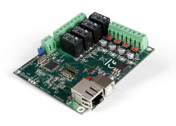
3 Introduction to the The is an Ethernet controlled board with 4 relay contacts, 4 digital inputs and 1 analog input. You can connect these I/O s to different devices and control or check them from anywhere you like using your PC, smartphone or tablet. The can also send notifications when the status of an input changes and features an embedded webserver. If you wish to control your with your smartphone or tablet, free apps are available for Android and ios. SPI Factory reset Analog input - + Max.30V / 2A 4 relay contacts UART Status LEDs P 5 PIC32MX695F VELLEMAN NV GND INPUT4 GND INPUT3 For inductive loads, add optional VDRs to protect relays (e.g., Velleman VDR250) Relay status LEDs Digital inputs accept dry contact or open collector INPUTx Reset button Power LED GND INPUT2 GND INPUT1 GND Ethernet connector USB (5 V) power supply input Digital input test buttons & status LEDs 3
4 1. Connecting the Ethernet relay card or First of all make sure you have a DHCP enabled network. If you don t know what DHCP is then don t worry, a regular home network is usually DHCP enabled. u Please make sure to upgrade your firmware to version 1.1. Download here: Please see section 4 of the user manual for more information on upgrading the firmware. Connect both the Ethernet cable and the USB cable into the. Afterwards, connect the Ethernet cable to your router and the USB cable to a USB power plug or USB port. The red and yellow LEDs should now be blinking. If the green led is on, you can proceed to the next instruction. To continue, download the ios- or Android app via the links below: ios: Android: Or install the PC application via the link below: Using the ios and Android app for the first time First, make sure your smartphone or tablet is connected to the same network/wi-fi as the. Then open the app and follow these simple steps to add your personal to your app: 1. Add a new relay card by tapping the <+> button. 4

5 2. Tap the <scan> button below to search for your. 3. Your should pop up in the list, be sure to select it. 5

6 4. Fill out the default credentials: Login: admin Password: (capital letters). We will explain how you can change your credentials later on. 5. Continue by tapping the <Save> button, there should be a Relay card added to the list now. 6
 or long press the name of your relay card (for Android) and tap <Edit>.")
7 6. Tap on the name of your newly added relay card (standard name is ) to go to the control page of your. Head forward to chapter 2. Controlling the and discover all the possibilities. 7. To edit your relay card, go back and slide over the name of your relay card to the left (for ios) or long press the name of your relay card (for Android) and tap <Edit>. If you wish to delete your relay card, tap <Delete>. 7

8 1.2 Using the PC application for the first time If you choose to use your PC to control the, make sure your PC is connected to the same network/wi-fi as the. Then open the discovery application and follow these simple steps to connect your : 1. Click the <Discover Devices> button. 2. A new row will be added. Click on your device and a webpage should open. 3. Fill out the default credentials: Login: admin Password: (capital letters). We will explain how you can change your credentials later on. 8
9 4. You now have access to the and will be able to control it. Head to the next chapter to discover the possibilities. 9
10 2. Controlling the The has 3 different Input/Outputs: relays, inputs and an analog input. By using these I/Os, you can read statuses from sensors or switches via the inputs and control devices via the relays. 2.1 Relay A relay (electro-mechanical switch) is used to switch external connected electrical devices. An external supply is used that suits the connected device. The relay does not generate any power; therefor it is a dry contact. u ATTENTION Take care not to exceed the relay rated voltage and current! Connect a relay to a device as shown in de diagram below: 12 V 12 V OFF ON PIC32MX695F P 5 VELLEMAN NV 10

11 Controlling the relay You can control the relays you connected via the Main page of your control panel by tapping/clicking on the <OFF> or <ON> button. The toggle buttons represent the current state of the relay. This means that if you see ON in the button, the relay is closed and is passing through current. If the button says OFF the relay is open and is not passing any current. 2.2 Input Inputs are used to sense whether 2 terminals are connected to each other or not. These digital inputs accept dry contact or open collector. u ATTENTION Do not connect external voltage to the inputs because this will destroy the! If the 2 wires are not connected, the status of the input will be OFF, if the 2 wires are connected the status of the input will be ON. PIC32MX695F P 5 VELLEMAN NV BUTTON 11

12 The status of the inputs can also be checked on the main page, here: 2.3 Analog input The analog input is a special kind of input which does not read 1 s and 0 s but measures the exact voltage on the input. This means you can read sensors like a thermistor or an anemometer. The grafic below shows an example of an analog and a digital signal: ANALOG 5V 2.5V 0V DIGITAL
13 The analog value can be read from the main page, here: 2.4 API (Application Programming Interface) The has an API which makes it easier for developers to control the relay card from their own application. The complete reference for accessing the API calls can be found in Settings and then API Reference. 2.5 Factory reset To return to the default settings, follow these steps: 1. First, make sure the power of the card is on (the yellow and red LEDs should be on). 2. Place a shunt (not incl.) on the factory reset pins (2 pins) next to the analog input. If you do not have a shunt, short the two pins with a conductive piece of metal/wire. 3. Unplug the USB cable (the yellow and red LEDs should now be off). 4. Remove the blue shunt or conductive piece. 5. Plug the USB cable back in. Make sure you follow the correct order! PIC32MX695F P 5 VELLEMAN NV 13
14 3. Editing the To start editing the, go to Settings in the left menu bar. 3.1 Credentials u WARNING changing the credentials will reboot the and all relays will be deactivated, make sure no machines are connected while doing this! If you want to control or edit the, you must first be authenticated. The default Login and password are still: Login: admin Password: (capitals) If you want to change the credentials go to Settings then Authentication. Fill out the form and click or tap <save and reboot>. 3.2 Network settings In general, the network settings are set up to suit your convenience and can remain unadjusted. If however you are an experienced user, we created an opportunity for you to adjust the network configuration of the. If you want to change the port* which the webserver is running on, you can change it by going to Settings and then Network. Now you can enter a new port in the web interface subsection. Click or tap <Save and reboot> to finalise. u WARNING If you click the save and reboot button, the will deactivate all relays. The webserver will restart with the new port and/or IP so the current webpage will not work. Browse to the new page with the correct port and/or IP. 14
15 3.3 settings The is capable of sending s even with SSL/TLS encryption. This makes the compatible with Gmail, Outlook, etc... In the settings, you can enter the address from which s will be sent via the. Go to Settings in the left menu bar and scroll down to the section. Fill out the credentials of your ISP or any webmail service and press <Save> to finalise. You can test your credentials by clicking <Test mail settings>. This will send an to the address that has been saved into the. If everything is filled out correctly, you will receive an saying If you received this mail, everything is OK. 15
16 3.4 IO settings It is possible to customize the IO names, set the Pulse time of the Relays, customize the look and feel and even the functionality of the website. Changing the IO names The name of the and all the relays and inputs can be changed by going to Settings, Customize and then fill out a new name in the name field of either the card name, relays or inputs (blue arrows). Don t forget to click <Save> when you are done. A specific card name makes it easy to browse to the relay card in your local network without remembering the IP address. It also makes it easy to distinguish multiple cards in the same network. If you give each relay and input a different name, it s easy to remember what the relay is controlling or what the input is reading. For example lights bathroom or doorbell. These names will also be used when sending s from the. Set the Pulse time Another customizable feature is activating the relays for a certain amount of time. This is the pulse feature. The length of the pulse can be set in the Pulse section using seconds (as shown in the picture above, red arrow). The pulse can work in two ways: The first way, as shown in the first diagram is when you activate the pulse when the relay was in the OFF state. The relay will be in the ON state for the amount of time that you have set. ON OFF TIME ACTIVATE PULSE END The second way is when you activate the pulse while the relay is already in the ON state. The relay will remain in the ON state for the amount of time that you have set. ON OFF TIME ACTIVATE PULSE END 16
17 The look, feel and functionality The two next fields in the Custom section are Custom js and Custom css. They allow you to add a URL to Javascript or a CSS file, which can alter the looks and functionality of the website. 3.5 Notifications The Notification settings allow you to enable and disable notifications for different actions. When an action is triggered an will be sent from the account you gave up in your settings. First make sure you enter the correct addresses to which you want to send the notifications (blue arrow). If you want to enter more then one address, type a ; inbetween the addresses with no spaces. For example: alice@ .com;trudy@ .com;john@ .com To disable the notifications, simply uncheck the Enabled box (red arrow). Don t forget to save! Actions There are 4 different actions to which you can enable an notification. You can choose one or more actions by opening the notification list (as shown in the picture) and selecting the actions you want to get notified of. We will now explain each action in detail. 17
18 A. Input rising: An will be sent if the corresponding Input transfers from a low to a high (or from off to on) state. For example: when the doorbell goes off. This can be done for each individual input. ON OFF TIME OFF = OPEN ON = CLOSED OFF = OPEN B. Input falling: An will be sent if the corresponding Input transfers from a high to a low (or from on to off) state. For example: when the heating is turned off. This can be done for each individual input. ON OFF TIME OFF = OPEN ON = CLOSED OFF = OPEN 18
19 C. Boot: When the is powered up and has an IP, the card will send an notifying you it started up. For example: when the power is rebooted after a power failure. D. Analog threshold: When the analog value reaches a specified value, it will send an . If the analog value goes below the threshold and then above, it will send an again. For example: if the temperature outside drops below 0C. The analog treshold is in this case 0. TEMPERATURE ANALOG TRESHOLD Analog treshold reached = TIME You can set the analog treshold value in the Alarm value box after you select this action in the list (see picture below).the alarm value must be between 1 and This value can be calculated by multiplying your voltage value times 155. For example if your voltage value is 3.3 V then the calculation is: 3.3 V * 155 = => 512. Floatingpoint numbers are not valid so round your value up or down. The maximum voltage that can be sensed is 6.6 V (=1024). 19
20 3.6 API The API key allows the user to login to the relay card without the credentials but with only a single key. This key is only valid when accessing the API urls that can be found in the API Reference page which will help you to control the relay card from your own programme. 3.7 API reference The API reference shows you a list of all commands and requests that can be made with your own programme. 3.8 About This section shows you the device information such as Board name, MAC address, System up-time, Firmware version, Analog max. value and Analog min. value. 20

21 4. Upgrading the firmware In case there is new firmware available or if there should be any problems with your Ethernet relay card, you can always reinstall/upgrade the firmware by following these steps. 1. Before we start, it is important to copy/remember/note your IP address for later on. You can find this either in the settings page of the app or in the IP column in the discovery software. You won t be able to do this after step Go to the download page of the on the Velleman website: Download the Firmware V Mount a shunt onto the factory reset pins (2 pins), located next to the analog input. If you do not have a shunt, short the two pins with a conductive piece of metal/wire. PIC32MX695F P 5 VELLEMAN NV 4. Power cycle the card by first unplugging the USB cable and then inserting it again. 21
22 5. Open the FW application which is included in the PC software. You can download this PC software on the product page here: 5. Hopefully you remembered your IP address! Copy it into the IP Address field and press <Connect>. Normally, you should see device connected. 6. Press <Load Hex File> and open the Hex file you downloaded during step 2. 22

23 7. Press <Erase - Program - Verify>, this will first reprogram the and then restart it. 23
24 ORDERCODE: REVISION: H 1 VELLEMAN nv - Legen Heirweg 33, Gavere (Belgium) vellemanprojects.com
IpAlarm Module Set Up
 Page 1 IpAlarm Module Set Up Note: This device is shipped configured for Ethernet connectivity. To use in this mode, connect the BLUE Jack (marked WAN) to your router and wait for the LEDs to stabilize.
IpAlarm Module Set Up VirtuAlarm model
 Page 1 IpAlarm Module Set Up VirtuAlarm model Note: This device is shipped configured for Ethernet connectivity. To use in this mode, connect the BLUE Jack (marked WAN) to your router and wait at least
The list of Events gives the detail of each modification of a sensor (date and time of the modification, person, setting modified)
") Page 1 / 30 1. Home page 2 2. Detail of an Item 3 3. Modification of the period of analysis 4 4. Quick change of settings 5 5. Create / modify Locations and Zones 6 6. Create / Modify Items 7 7. Create
Page 1 / 30 1. Home page 2 2. Detail of an Item 3 3. Modification of the period of analysis 4 4. Quick change of settings 5 5. Create / modify Locations and Zones 6 6. Create / Modify Items 7 7. Create
The GV-I/O Box 16 Ports provides 16 inputs and 16 relay outputs, and supports both DC and AC output voltages.
 GV-I/O Box 16 Ports The GV-I/O Box 16 Ports provides 16 inputs and 16 relay outputs, and supports both DC and AC output voltages. Key Features 16 inputs and 16 outputs are provided. Up to 9 pieces of GV-I/O
SETUP GUIDE INSTALLATION HANDBOOK. For Integrators, Installers and Administrators. Everything on how to get Kisi up and running. getkisi.
 SETUP GUIDE INSTALLATION HANDBOOK For Integrators, Installers and Administrators Everything on how to get Kisi up and running getkisi.com 1 TABLE OF CONTENT 13 14 INSTALLING KISI AS A STAND-ALONE SYSTEM
Contents. 1 Register and Configure Hi-Gate Add Sensor Node Create a Fresh New Project... 6
 Contents 1 Register and Configure Hi-Gate... 2 1.1 Add Sensor Node... 4 1.2 Create a Fresh New Project... 6 1.3 Project Testing on Real Hardware... 9 1.4 Troubleshoot Guide... 10 2 Connection Modes: WiFi,
Sygonix Home Starter Kit
 App Instruction Manual Sygonix Home Starter Kit Item No. 1597114 www.conradconnect.de Contents Conrad Connect... 4 Symbols... 4 Core functions... 5 App to device communication... 6 App Installation...
Zavio P5111/ P5116/ P5210 Quick Installation Guide
 86085M2000010 Zavio P5111/ P5116/ P5210 Quick Installation Guide Installation Steps Please follow the installation steps below to set up your P5111 / P5116/ P5210 Day/Night Pan/Tilt IP Camera. Check the
How to update firmware on a DVR/NVR
 How to update firmware on a DVR/NVR Warning: You need to log in to your DVR and do Reset to Factory Default before you start upgrading the firmware. Log in to DVR Main Menu Settings Systems Default (All
Firmware Revision History and Upgrade Instructions
 SENSAPHONE Firmware Revision History and Upgrade Instructions Equipment Firmware: WEB600 v1.46 WEB600 with Relay Output v1.59 Release Date: July 15, 2013 The upgrade package has no prerequisites and supersedes
P6210 PN: 86085A A
 P6210 1 PN: 86085A1000010 86085A1000000 Zavio P6210 Quick Installation Guide Please follow the installation steps below to set up P6210 Pan/Tilt IR Dome IP Camera. Check the package contents against the
F3102 / F3107 / F3110 / F3115 / F3210 / F3215 PN: 86085K K
 F3102 / F3107 / F3110 / F3115 / F3210 / F3215 86085K3000020 PN: 86085K3000030 Zavio F3102/F3107/F3110/F3115/F3210/F3215 Quick Installation Guide Please follow the installation steps below to set up F3102
Product Manual. Rimikon IP CONTROLLER Model No: RIM-IPC V.02. P a g e 1
 P a g e 1 www.rimikon.com Product Manual Rimikon IP CONTROLLER Model No: RIM-IPC V.02 P a g e 2 Product Description The Rimikon IP Controller is designed to work with all of Rimikon s Low Voltage LED Lighting
ETH044-4 SSR (230VAC) and 4 Digital IO
 and 4 Digital IO") ETH044-4 SSR (230VAC) and 4 Digital IO Technical Documentation WARNING Mains Voltages can be Lethal. If you are not confident with using these voltages, please use a qualified electrician to wire this
ETH044-4 SSR (230VAC) and 4 Digital IO Technical Documentation WARNING Mains Voltages can be Lethal. If you are not confident with using these voltages, please use a qualified electrician to wire this
Innovative Electronics for a Changing World INDEX
 Innovative Electronics for a Changing World INDEX 1. SYSTEM DESCRIPTION 2. BOARD CONNECTIONS terminals and indicators 3. CONNECTION DIAGRAM 4. START UP GUIDE and passwords 5. HOME PAGE 6. STATUS PAGE 7.
Quick Install Guide. Model: PLC-223W, PLC-233W
 Quick Install Guide Model: PLC-223W, PLC-233W This installation guide provides basic instructions for installing the PLC-213W/ PLC-223W/PLC-233W indoor wireless IP camera on your network. By following
owncloud Android App Manual
 owncloud Android App Manual Release 2.0.0 The owncloud developers December 14, 2017 CONTENTS 1 Using the owncloud Android App 1 1.1 Getting the owncloud Android App...................................
TABLE OF CONTENTS COPYRIGHT INTRODUCTION...3 PRODUCT OVERVIEW...3 COMPONENTS AND FEATURES...3 HARDWARE INSTALLATION
 TABLE OF CONTENTS COPYRIGHT...2 1. INTRODUCTION...3 PRODUCT OVERVIEW...3 COMPONENTS AND FEATURES...3 HARDWARE INSTALLATION...3 2. MFP SERVER INSTALLATION...5 PREPARATION...5 CONFIGURATION SOLUTION TABLE...5
Longshine Technologie Europe GmbH
 Longshine Technologie Europe GmbH www.longshine.de TABLE OF CONTENTS COPYRIGHT...2 1. INTRODUCTION...3 PRODUCT OVERVIEW...3 COMPONENTS AND FEATURES...3 HARDWARE INSTALLATION...3 2. MFP SERVER INSTALLATION...5
INDEX. Network Power Monitor R10 SNMP
 Innovative Electronics for a Changing World NPM-R10 Remote Network Power Monitor With optional relay board and GSM module INDEX Amended 21 March 2017: Add user defined Password see page 13 Add wire Connection
VEGA. Operation Manual T A B L E T P C. advent vega operation manaul_new.indd 1
 VEGA T A B L E T P C Operation Manual advent vega operation manaul_new.indd 1 advent vega operation manaul_new.indd 2 CONTENTS SETTING UP YOUR TABLET FOR THE FIRST TIME... 4 USING THE DEVICE S BUTTONS
Firmware User Manual. Firmware version v1.0. Suitable for Product Series: Touch Panel PC Panel PC Box PC. QD-FW_Manual_v1.0
 1 Firmware User Manual Firmware version v1.0 Suitable for Product Series: Touch Panel PC Panel PC Box PC 2 Contents Features 3 System setup 3 System start up 3 System Settings 4 System Information 9 System
Configuration. Guides on how to configure BarWeb hosted accounts. Exchange Accounts. Outlook Windows. Outlook Windows
 Email Configuration Guides on how to configure BarWeb hosted email accounts Exchange Accounts Outlook 2016 - Windows Outlook 2013 - Windows Outlook 2010 - Windows Windows Mail Android iphone/ipad MacMail
INDEX. Network Power Monitor NPM-R10-SNMP. Innovative Electronics for a Changing World. NPM-R10-SNMP Remote Network Power Monitor
 Innovative Electronics for a Changing World NPM-R10-SNMP Remote Network Power Monitor Optional relay board and GSM module INDEX 1. SYSTEM DESCRIPTION 2. SYSTEM BATTERY CONNECTIONS 3. SERIES CONNECTED BATTERIES
SVT-WIFI Video Intercom System C
 SVT-WIFI Video Intercom System C User Manual Please read this user manual prior to installing the system, and keep it well for future use. CONTENTS 1. Parts and Functions... 1 2. Terminal Descriptions...
Configuring the LxOEM
 Technical Instruction The LxOEM lighting controller is designed to be configured in several ways. As a programmable controller, it can be fully programmed and configured at the ligthing panel manufacturing
Bush Baby Wi-Fi Wall Outlet Hidden Camera
 Bush Baby Wi-Fi Wall Outlet Hidden Camera SKU: BBWiFiWallOutlet 1 Version 1.1 THANK YOU FOR PURCHASING THE BBWIFIWALLOUTLET Please read this manual before operating the BBWIFIWALLOUTLET and keep it handy.
Instruction Manual. Wi-Fi Full HD 1080p IP Concealed Junction Box Hidden Camera. V 1.3
 Instruction Manual Wi-Fi Full HD 1080p IP Concealed Junction Box Hidden Camera After Sales Support techsupport@123anfang.com www.yooseecamera.com V 1.3 Hardware Installation 1. Connect the power supply
GET STARTED AC 1200 High Power Dual Band Wi-Fi Range Extender
 GET STARTED AC 1200 High Power Dual Band Wi-Fi Range Extender Overview 01 Package Contents... 01 Front Panel... 02 LED Descriptions... 03 Using as an Extender 04 Connects to a WIFI network... 04 Acts as
Longshine Technologie Europe GmbH LCS-MFP101-2 Multifunction Printserver
 Longshine Technologie Europe GmbH LCS-MFP101-2 Multifunction Printserver www.longshine.de TABLE OF CONTENTS COPYRIGHT...2 1. INTRODUCTION...3 PRODUCT OVERVIEW...3 COMPONENTS AND FEATURES...3 HARDWARE INSTALLATION...3
User Manual. Microdigital IP cameras with built-in Ivideon software
 User Manual Microdigital IP cameras with built-in Ivideon software Table of Contents Introduction to Ivideon... What is Ivideon about?... Why use an IP camera with built-in Ivideon software?... How to
Orbi WiFi System User Manual
 User Manual February 2018 202-11675-09 350 E. Plumeria Drive San Jose, CA 95134 USA Support Thank you for purchasing this NETGEAR product. You can visit www.netgear.com/support to register your product,
Wireless Advisor Advanced Pedestrian System (WiAAPS) Common Procedures
 Common Procedures") Wireless Advisor Advanced Pedestrian System (WiAAPS) Common Procedures Table of Contents 1 Introduction... 2 2 Accessing the Webpage... 3 3 Swapping Out a WiAPB... 4 4 Swapping Out a WiAPC... 7 5 Adding
Wireless Advisor Advanced Pedestrian System (WiAAPS) Common Procedures Table of Contents 1 Introduction... 2 2 Accessing the Webpage... 3 3 Swapping Out a WiAPB... 4 4 Swapping Out a WiAPC... 7 5 Adding
D4210 PN: 86085A
 D4210 1 PN: 86085A2000000 Zavio D4210 Quick Installation Guide Please follow the installation steps below to set up D4210 IR Dome IP Camera. Check the package contents against the list below. See P.1
INSTRUCTIONS TO UPDATE FIRMWARE FOR
 INSTRUCTIONS TO UPDATE FIRMWARE FOR Dranetz 1000 New Durham Road, Edison, New Jersey 08818 Telephone 1-800-372-6832 or 732-287-3680 Fax 732-248-1834 www.dranetz.com Updating the HDPQ SP s Firmware The
User Manual. AC ac Wireless Access Point/Router. Model WAC124. NETGEAR, Inc.
 AC2000 802.11ac Wireless Access Point/Router Model WAC124 December 2018 202-11885-02 NETGEAR, Inc. 350 E. Plumeria Drive San Jose, CA 95134, USA AC2000 802.11ac Support Thank you for purchasing this NETGEAR
Magnetic base Indicator light Microphone Camera lens Micro SD card slot Infrared light Front Side Pivot connector Built-in speakers
 Niro USER MANUAL Contents Introduction 4 Product Features 5 Niro LED Indicators 6 What s Included 7 Wi-Fi Requirements 8 Mobile Device Requirements 8 Garage Door Opener Requirements 8 Download the Momentum
FAQ for KULT Basic. Connections. Settings. Calls. Apps. Media
 FAQ for KULT Basic 1. What do the Icons mean that can be found in notifications bar at the top of my screen? 2. How can I move an item on the home screen? 3. How can I switch between home screens? 4. How
Version 13. Cisco to Meraki Firewall Upgrade Graphical Instructions
 Version 13 Cisco to Meraki Firewall Upgrade Graphical Instructions We are pleased to provide this technology to upgrade Church meetinghouse networks. The upgrade process has been simplified, and these
Instructions for SimplicityTouch ST-700 Gen 3 TECHNICAL TRAINING GUIDE
 Page 1 Instructions for SimplicityTouch ST-700 Gen 3 TECHNICAL TRAINING GUIDE Manuals included in guide: 1. Update panel firmware and reinstall applications. page 2 2. Update router firmware page 10 3.
SERIAL PORT TOOL. N-Button Lite Quick Start Guide
 SERIAL PORT TOOL N-Button Lite Quick Start Guide SERIAL PORT TOOL N-Button Lite Quick Start Guide Copyright 2014 All Rights Reserved. Notice: Portions of this manual require internet access. Table of Contents
Table of Contents. The Botron B92700 OMNIGND is a Multi-Ground Continuous Monitoring Automation System.
 Operation Manual Table of Contents Description: The Botron B92700 OMNIGND is a Multi-Ground Continuous Monitoring Automation System. Directory: Overview Pg. 2 Features Pg. 3 Quick Setup Guide Pg. 3 Settings
WI-FI GARAGE DOOR CONTROLLER WITH CAMERA USER MANUAL
 WI-FI GARAGE DOOR CONTROLLER WITH CAMERA USER MANUAL Contents Introduction 4 Product Features 5 Garage Door Controller LED Indicators 6 What s Included 7 Wi-Fi Requirements 8 Mobile Device Requirements
Contents. GV-I/O Box 8 Ports Key Features Compatible Software Packing List Overview DIP Switch...
 Contents GV-I/O Box 8 Ports...2 1. Key Features... 2 2. Compatible Software... 2 3. Packing List... 2 4. Overview... 3 5. DIP Switch... 3 6. Connections to PC... 4 6.1 Installing USB Driver... 5 6.2 Assigning
Innovative Electronics for a Changing World. NPM-R10 Remote Network Power Monitor. With optional relay board and GSM module INDEX
 Innovative Electronics for a Changing World NPM-R10 Remote Network Power Monitor With optional relay board and GSM module INDEX 1. SYSTEM DESCRIPTION 2. BOARD CONNECTIONS terminals and indicators 3. CONNECTION
8-Port Gigabit Ethernet Smart Managed Plus Switch with Integrated Cable Management User Manual
 8-Port Gigabit Ethernet Smart Managed Plus Switch with Integrated Cable Management User Manual Model GS908E December 2017 202-11807-03 350 E. Plumeria Drive San Jose, CA 95134 USA Support Thank you for
Welcome Contents Diagram
 Welcome Congratulations on your purchase of our GBF PL960 Series of IP Doorbells. Our factory engineers were the first to enable viewing of multiple security cameras through your handheld smart device,
WELCOME. For customer support or any inquiries, please visit our web site at or contact us at
 WELCOME Congratulations on purchasing the GBF Smart Four Wire Intercom System. Our factory engineers were the first to enable multiple security cameras being monitored through a smart mobile device and
UserGuide_TempSensor_with_Alarms Issue 4/
 SPECTECS TEMPERATURE SENSOR WITH ALARMS ( Wi-Fi enabled with optional module ) Embedded control EMC1001 sensor Range 0C to +125C Resolution 0.25C Accuracy +/-1.5C, 40 to 85C USB powered or external 2.2-16V
A Connect the Broadband Router
 A CheckPoint FTS Broadband Linksys WRT54G Router Setup V2 A Connect the Broadband Router PRINT THIS DOCUMENT FOR REFERENCE IMPORTANT: Before you begin, disconnect any computers that are connected to your
Version /13/2014. User Manual. mydlink Home Smart Plug DSP-W215
 Version 2.00 08/13/2014 User Manual mydlink Home Smart Plug DSP-W215 Preface D-Link reserves the right to revise this publication and to make changes in the content hereof without obligation to notify
ZAVIO Indoor Box Camera. Quick Installation Guide
 ZAVIO Indoor Box Camera Quick Installation Guide 1 Quick Installation Guide Please follow the installation steps below to set up your IP camera. Check the package contents with the list below. See P.2
THE SHADE STORE MOTORS WITH AMAZON ALEXA
 THE SHADE STORE MOTORS WITH AMAZON ALEXA ABOUT THE SKILL: The Shade Store s motorized window treatments can be voice controlled easily through Amazon Alexa. Simple commands allow you to raise and lower
Setup Guide for Wi-Fi Hotspot Boosting Kit
 Setup Guide for WI-KIT-02 Wi-Fi Hotspot Boosting Kit Congratulations on purchasing the WI-KIT-02, this contains everything you need to be able to connect to Wi-Fi at a camp site / marina / other location.
Cloud IP Camera Note:
 Version:V2.0 Cloud IP Camera User s Manual Note: To protect your privacy, please change the initial password after login. Please keep your user name and password safely. Contents 1. Introduction... 2 1.1
DENT Instruments ELITEpro Mobile App
 DENT Instruments ELITEpro Mobile App Version 3.0 Instruction Guide Revision: Final Draft May 20, 2015 Page 2 of 16 Instruction Guide: ELITEpro Mobile App 2015 DENT Instruments, Inc. All rights reserved.
Super USB. User Manual. 2007, March
 Super USB User Manual 2007, March Windows98 Driver Install/Uninstall Driver Install: 1. Execute Win 98 UFD driver, then restart PC. 2. Plug Super USB into an available USB port. A new Removable Disk drive
C1002 IP Camera. Quick Installation Guide. Solwise Ltd., 1
 C1002 IP Camera Quick Installation Guide Solwise Ltd., www.solwise.co.uk, sales@solwise.co.uk 1 Trademarks and/or registered trademarks are the property of their respective owners The information presented
DMS Local. User Manual. For Projector Management V 1.01
 DMS Local User Manual For Projector Management V 1.01 2 Copyright Copyright Copyright 2018 BenQ Corporation. All rights reserved. No part of this publication may be reproduced, transmitted, transcribed,
Technical Training Guide for SimplicityTouch IFP Model Numbers Covered: 70 ST-700, Generation 2 (802.11ac)
") TM TM Technical Training Guide for SimplicityTouch IFP Model Numbers Covered: 70 ST-700, Generation 2 (802.11ac) Last Update: 01-29-16 e: support@recordexusa.com TOPICS COVERED: 1) Update Panel Firmware
TM TM Technical Training Guide for SimplicityTouch IFP Model Numbers Covered: 70 ST-700, Generation 2 (802.11ac) Last Update: 01-29-16 e: support@recordexusa.com TOPICS COVERED: 1) Update Panel Firmware
LonHand Series Product Specification USR-R16-T
 LonHand Series Product Specification USR-R16-T Ver: V1.0 Jinan USR IOT Technology Limited 1 / 19 sales@usr.cn 目录 LonHand Series Product Specification...1 1 Quick start... 3 1.1 Product Brief Introduction...
Heatmiser Netmonitor v3
 Heatmiser Netmonitor v3 Technical Set-Up (Firmware Version 3.5 or above) Function Page Number Connecting to your Netmonitor 2 Changing the Netmonitor IP address 4 Accessing the Netmonitor over the Internet
User Guide for Client Remote Access. Version 1.2
 User Guide for Client Remote Access Version 1.2 Table of Contents PAGE Introduction... 2 Microsoft Multi-Factor Authentication Introduction... 3-4 User Enrollment... 5-8 Accessing Remote Resources Windows
IP Camera User Manual
 the world through my eyes R IP Camera User Manual EN App Store Google Play Version:TWS20180723 1Product description 1.1Product Feature 1.2Package Contents 1.3IP Camera Overview 1.4Operating System Requirement
SoundEar 3 micro PC manual Ver.5.2.6
 SoundEar 3 micro PC manual Ver.5.2.6 Table of Contents Introduction... 2 Choosing your connection... 2 Set a new site ID... 2 Configure your SoundEar 3 device... 4 Connecting to either cloud broker or
BITMAIN. S4+ Server Manual
 BITMAIN S4+ Server Manual Page 2 of 10 Contents 1 Overview... 3 2 Features... 3 3 Connect to Server... 3 4 Server Configuration... 6 4.1 Pool Setting... 6 4.2 Frequency Modification... 6 5 Server Status...
Energy Client. Version Feb Electrocom Rødeledsvej 95 DK-5700 Svendborg Denmark Tel:
 Energy Client Version 2.0.806 3. Feb. 2014 Electrocom Rødeledsvej 95 DK-5700 Svendborg Denmark Tel: +45 88 80 75 80 www.electrocom.dk p. 2 Introduction... 3 Installation... 4 LED, Switches and Reset...
Connecting to your Caravan or Motorhome
 Welcome to Swift Command This document will show you how to connect the Swift Command App to your Caravan or Motorhome and then explain the key features and their operation. Control your lighting and adjust
AC1900 WiFi Mesh Extender Essentials Edition
 AC1900 WiFi Mesh Extender Essentials Edition Model EX6400 User Manual July 2018 202-11611-03 350 East Plumeria Drive San Jose, CA 95134 USA Support Thank you for purchasing this NETGEAR product. You can
WF-2402 Quick Installation Guide
 WF-2402 Quick Installation Guide Netis 150Mbps Wireless-N Broadband Router 1. Check Your Package Contents The following items should be found in your package: 150Mbps Wireless-N Broadband Router Power
HomeTroller Zee S2 Getting Started Guide
 HomeTroller Zee S2 Getting Started Guide Congratulations on your purchase! Your HomeTroller Zee S2 is ready to put you in control of your home. Please take a few minutes to read through this guide to familiarize
RV2458 Router User Manual
 RV2458 Router User Manual For Technical Assistance, please call (800) 638-3600, or visit www.magnadyne.com Contents Establish a WiFi Connection............... 3 Pair RV2400(MV2400)........................
HomeTroller Zee Quick-Start Guide
 HomeTroller Zee Quick-Start Guide Congratulations on your purchase! Your HomeTroller Zee is ready to put you in control of your home. Please take a few minutes to read through this guide to familiarize
Intel Entry Storage System SS4000-E
 Intel Entry Storage System SS4000-E Software Release Notes January 2007 Storage Systems Technical Marketing Engineering Document Revision History Intel Entry Storage System SS4000-E Document Revision History
EP2 EP8 User Manual. Copyright 2007,ATAL
 EP2 EP8 User Manual Copyright 2007,ATAL 1) Introduction 1. What is EP? 2. What s the difference between the EP2 and the EP8? 3. How to use this manual 4. EP2 5. EP8 2) Installation 1. Assigning an IP address
1. Press "Speed Test" to find out your actual uplink and downlink speed.
 ASRock G10 Gaming Router 6.4 QoS Settings QoS Add Gaming Boost web page. Gaming Boost: Enable or disable the Gaming Boost. Bandwidth The router supports Gaming Boost natively, which identifies and intelligently
User manual. tel.+ (48)
") ilock User manual system User manual contact@ilocksystems.com www.ilocksystems.com tel.+ (48) 61 669 06 87 e-mail: contact@ilocksystems.com www.ilocksystems.com technical support: support@ilocksystems.com
ilock User manual system User manual contact@ilocksystems.com www.ilocksystems.com tel.+ (48) 61 669 06 87 e-mail: contact@ilocksystems.com www.ilocksystems.com technical support: support@ilocksystems.com
960P and 1080P HD Video Security DVR System User Manual
 960P and 1080P HD Video Security DVR System User Manual www.tigersecu.com Copyright 2017 TIGERSECU, Inc Contents Contents... 1 Important Information...3 Installation Guide....4 Chapter 1. Start-up Wizard...6
Amcrest 960H DVR Quick Start Guide
 Amcrest 960H DVR Quick Start Guide Version 2.0.2 Revised July 22, 2015 Welcome Thank you for purchasing our Amcrest 960H DVR! This quick start guide will help you become familiar with our DVR in a very
Quick Start Guide. GV-Video Server. 1 Introduction. Packing List
 Introduction Quick Start Guide GV-Video Server Welcome to the GV-Video Server Quick Start Guide. In the following sections, you will learn about the basic installations and configurations of the GV-Video
5.1 Configure each Sensor Pin Rename Set Rules Export Data Switching Nodes... 25
 Hi-Gate User Manual Hi-Gate User Manual Hi-Gate User Manual Contents 1 Introduction... 3 1.1 Hi-Gate... 3 1.1.1 What is Hi-Gate... 3 1.1.2 Specifications... 3 1.1.3 Features... 4 1.2 Hi-Node... 5 1.2.1
QUICK GUIDE. Camera Installation for iphone, ipad, Android smart phone and tablet
 QUICK GUIDE Camera Installation for iphone, ipad, Android smart phone and tablet For Technical questions, please email: info@trivisiontech.com 1 Contents 1.0 Introduction ----------------------------------------------------------------------3
EC-11 Ethernet Converter
 EC-11 Ethernet Converter PSTN Contact ID to TCP Converter Installation and Operations Manual Version 8.H3.MID 1 Table of Contents About EC-11 Ethernet Converter... 3 Circuit Board Layout and Wiring Diagram...
Installing the Linksys app on your Android device via the Google Play Store and Google Play Website
 User Guide Installing the Linksys app on your Android device via the Google Play Store and Google Play Website The Linksys app is a free mobile application that allows you to securely access your home
MARQUE: GARMIN REFERENCE: EX FRS CODIC: NOTICE
 MARQUE: GARMIN REFERENCE: EX3800-100FRS CODIC: 4121198 NOTICE Model EX3800 User Manual May 2015 202-11488-01 350 East Plumeria Drive San Jose, CA 95134 USA Support Thank you for selecting NETGEAR products.
Amcrest Eco HDCVI DVR Quick Start Guide
 Amcrest Eco HDCVI DVR Quick Start Guide Version 1.0.1 Revised August 13th, 2015 Welcome Thank you for purchasing our Amcrest Eco HDCVI DVR! This quick start guide will help you become familiar with our
RN-171-EK Evaluation Board
 RN -17 1-E K-DS RN-171-EK Evaluation Board Features Ultra-low power: 4-uA sleep, 40-mA Rx, 180-mA Tx at 10 dbm Configurable transmit power: 0 to +12 dbm UART hardware interfaces and SPI slave Up to 1 Mbps
BlackVue C App Manual
 BlackVue C App Manual BlackVue C App Manual Contents Connecting to BLACKVUE CLOUD... 3 (A) Create an account... 3 (B) Register your dashcam with your account... 3 (C) Connect your BlackVue dashcam to a
IP Energizer Instructions
 IP Energizer Instructions IP Energizer Instructions Versions: IP Energizer Controller 1.31 PAE025 3v26 Introduction In order to allow remote control of the IP Energizer you will need to set up its Wi-Fi
Network USB over IP Server With 1-USB2.0 Port. User Manual V1.0
 Network USB over IP Server With 1-USB2.0 Port User Manual V1.0 1 2 TABLE OF CONTENTS COPYRIGHT...4 1. INTRODUCTION...5 PRODUCT OVERVIEW...5 COMPONENTS AND FEATURES...5 HARDWARE INSTALLATION...5 2. THE
DCS-8000LH. HW Version FW Version App Name App Version. A1 V Mydlink Lite V3.8.0
 DCS-8000LH HW Version FW Version App Name App Version A1 V1.00.05 Mydlink Lite V3.8.0 Contents Q1: How to setup DCS-8000LH using mydlink Lite App?... 2 Q2: How to setup Motion detection?... 7 Q3: How to
Connecting to Director. Before setting up Director for the first time run through the check list below:
 Connecting to Director Before setting up Director for the first time run through the check list below: 1.Are both the lights and router within reasonable distance from Director and all components preferably
F100 Basic Setup Instructions
 F100 Basic Setup Instructions Basics The F100W-LPG (F100) sends LPG tank level information to an email address using the WiFi network where an LPG tank is located. The F100 unit can be setup without being
Cloud IP Camera Note:
 Version:V2.0 Cloud IP Camera User s Manual Note: Due to the continuous updating of the product and software, there may be a discrepancy between the operating guide and the APP interface.all the instructions
USER MANUAL FOR MF0200 GATEWAY BOX VERSION 2.0
 USER MANUAL FOR MF0200 GATEWAY BOX VERSION 2.0 COPYRIGHT & TRADEMARKS 2016 Mentor Graphics Corporation, all rights reserved. This document contains information that is proprietary to Mentor Graphics Corporation
Panoramic Fisheye IP Camera. Quick Installation Guide
 Panoramic Fisheye IP Camera Quick Installation Guide 8608595330000 Please follow the installation below steps to set up Panoramic Fisheye IP Camera. Check the package contents against the list below.see
SAS-IPCAM115 SAS-IPCAM116 MANUAL IP CAMERA
 SAS-IPCAM115 SAS-IPCAM116 MANUAL IP CAMERA Table of contents Introduction: Safety precautions: Packaging content: System requirements: Product description: User instructions: Maintenance: Warranty: Disclaimer:
Premiertek AP Mbps Wireless-N Broadband Router Quick Installation Guide
 Premiertek AP2402 150Mbps Wireless-N Broadband Router Quick Installation Guide V1.0.8.11 1. Check Your Package Contents The following items should be found in your package: 150Mbps Wireless-N Broadband
Table of Contents. Camera Anatomy... pg 1. Package Contents... pg 2. Camera Assembly... pg 3. Account Login... pg 5. Adding a New Camera...
 Table of Contents Camera Anatomy... pg 1 Package Contents... pg 2 Camera Assembly... pg 3 Account Login... pg 5 Adding a New Camera... pg 6 Wireless Configuration... pg 9 WPS Enabled Routers... pg 13 Technical
3G WIFI ROUTER/POWERBANK Quick Guide
 3G WIFI ROUTER/POWERBANK Quick Guide The factory default password WIFI connection: 12345678 Initial Account: admin Default password: admin Ports: 21 3GWi-Fi is one Power bank and mobile 3G wifi router