FIELDBUS TECHNOLOGY ETHERNET- PROFIBUS- INTERFACE PB-XEPI F1144/ 03 INSTALLATION MANUAL
|
|
|
- Elmer Cunningham
- 6 years ago
- Views:
Transcription


1 FIELDBUS TECHNOLOGY ETHERNET- PROFIBUS- INTERFACE PB-XEPI INSTALLATION MANUAL F1144/ 03
2 2 Installation PB-XEPI D
3 Content About this "Installation manual"...5 Intended use...5 Explanation of the safety instructions...5 Menu and keyboard commands...5 For your safety...6 Performance and functioning...8 PB-XEPI features...8 Scope of delivery...8 PB-XEPI Configuration requirements...8 Ethernet network presettings...8 Design of the device...9 Connections and indicating elements...10 Mounting...10 Start-up guideline...11 Note regarding the application software...11 Assembling and disassembling the device...12 Assembling the device...12 Disassembling the device...12 Connecting the Ethernet...12 Connecting the power supply...13 Configuring the device in the Ethernet network...14 Connection in a network with DHCP (Dynamic Host Configuration Protocol)...14 Connection in a network with manual IP assignment...15 Determining the network addresses...16 Setting the new IP and network addresses...16 Checking the Ethernet connection to the device...17 Connecting the PROFIBUS...18 Bus terminating resistors...19 D Installation PB-XEPI 3
4 Content PB-XEPI operation modes PROFIBUS Diagnosis...20 PROFIBUS network access...21 Troubleshooting...22 Technical data Installation PB-XEPI D
5 About this "Installation manual" About this "Installation manual" Please read this manual carefully, prior to installation. It facilitates assembly and setup of your system and provides you with important information. Intended use The device is designed to be used as an interface between PROFIBUS and Ethernet networks. Any other use is deemed non-intended use. Explanation of the safety instructions The following symbols and signal words used are intended to draw your attention to special situations: Danger Warning of personal injury from voltage. Warning Warning of damage to device. Note Useful tips. Disposal Notes on disposal. Menu and keyboard commands The following conventions apply to menu and keyboard commands: Courier font <Key> Window names, menu items, fields and descriptions of combo boxes, check boxes, radio buttons and icons. Press the indicated key. D Installation PB-XEPI 5
6 For your safety For your safety Strictly observe the following safety instructions before connecting the device: Warning Never open the case of the device or carry out any mechanical modifications on the device. Otherwise, this may lead to damages on the device as well as to loss of warranty. Warning The device contains electronic components sensitive to electrostatic discharges. Damages due to electrostatic discharge can lead to premature failure of components or intermittent faults at a later stage. Before installing the device, divert the electrostatic discharge away from your body and the tools used. Warning Small objects or liquids must not enter the case of the device (e.g. through the ventilation slots). This may damage the device. Never cover the ventilation slots on the device. Carefully plan the integration of the device into an existing system and ensure a proper function of the system after installation. The device may only be assembled or disassembled by qualified, trained electrical engineering personnel. When installing the device, observe the regulations for handling electric components in accordance with VDE In addition, you must also observe the valid safety and accident prevention regulations (UVV) when operating the device within the jurisdiction of the Federal Republic of Germany. Observe the EN PROFIBUS norm. Always install the device on a suitable DIN-rail (mounting rail). Cables used for the connection must not apply any mechanical forces to the device. High temperature differences between the storage site and installation site can result in condensation within the case, which may cause the device to become damaged. In case of high temperature differences, please wait at least three hours before operating the device. Lock the connected plug (PROFIBUS) using the screw connections intended for this purpose. 6 Installation PB-XEPI D
7 For your safety Disposal The device must be disposed of separately from normal household waste in accordance with the 2002/96/EC (WEEE) Directive. D Installation PB-XEPI 7
8 Performance and functioning Performance and functioning The Ethernet-PROFIBUS-Interface (PB-XEPI) as a compact gateway enables an easy connection of PROFIBUS networks to the Ethernet. PB-XEPI features Supports 2 operation modes: integrated PROFIBUS diagnosis of the entire PROFIBUS network with alert via and PROFIBUS network access for other applications like PROFIBUS Scope from Trebing & Himstedt, TH OPC Server DP from Trebing & Himstedt, FDT frame application with CommDTM PROFIBUS DP-V1 from Trebing & Himstedt or Emerson s AMS Suite Supports leading technologies such as FDT, EDD (Emerson s AMS Suite), OPC Supports central field device configuration, calibration and diagnosis, e.g. via configuration tools such as FieldCare of Endress + Hauser, FieldMate from Yokogawa, PACTware or Emerson s AMS Suite Independent of process control system or PLC manufacturers Supports condition monitoring Support smart-devices asset management Scope of delivery Ethenet-PROFIBUS-Interface PB-XEPI Documentation PB-XEPI Configuration requirements (not included in the scope of delivery) PC or notebook with Windows 2000, XP or Server 2003 (operating system dependent on the application software used) Web browser (MS Internet Explorer 6 or 7) for configuration of Ethernet and PROFIBUS diagnosis Application software for PROFIBUS configuration Enabling the ports 80 and 2364 Ethernet network presettings The device is preset to Ethernet network operation with a DHCP server. No Ethernet configuration settings are required in this operating mode. In case of manual allocation of IP addresses the device has the following standard IP: configuration: IP address Subnet mask Standard gateway Installation PB-XEPI D
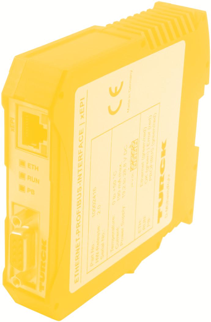
9 Design of the device Design of the device (see Fig. 1) 1 Ethernet interface 5 PROFIBUS interface 2 LED ETH 6 Terminal strip for power supply 3 LED RUN 7 Type label 4 LED PB 8 DIN-rail (not included in the scope of delivery) [1] [2] [3] [4] ETH RUN PB [8] PB-XEPI [5] [6] A B C D [7] PB-XEPI Ident No.: HW-Release: 2.0 Serial No.: Temperature: C Current: max. 190 ma Power Supply: 19,2...28,8 VDC + 24 VDC ETH: RUN: PB: Ethernet (GN/RD) OK (GN) Error (RD) PROFIBUS (GN/RD) Made in Germany D-Mülheim/Ruhr Fig. 1: PB-XEPI (front and side view) D Installation PB-XEPI 9
10 Connections and indicating elements Connections and indicating elements [1] Ethernet interface: RJ45 (10Base-T/100Base-TX) LED lights yellow: Ethernet data communication LED lights green: physical connection available [2] LED ETH ETH lights red: first start phase ETH flashes red: boot procedure ETH lights red or flashes red or green in case of an error: internal failure of the firmware. ETH lights green: connection to application via Ethernet [3] LED RUN RUN lights red: internal failure identified RUN lights green: 24 V power supply is fed [4] LED PB PB lights or flashes green: device communicates via PROFIBUS [5] PROFIBUS interface: D-Sub socket [6] Terminal strip for +24 VDC power supply A: 24 V (+) B: 0 V (-) C: not assigned D: Earth conductor Mounting 35 mm DIN rail [8] (not included in the scope of delivery) 10 Installation PB-XEPI D
11 Start-up guideline Start-up guideline The following steps are required for start-up: 1. Mount the device (see»assembling the device«on page 12). 2. Connect to the Ethernet (see»connecting the Ethernet«on page 12). 3. Connect to the power supply (see»connecting the power supply«on page 13) 4. Configure the Ethernet (see»configuring the device in the Ethernet network«on page 14). Note To set the IP address manually you must connect your computer to the device via a patch cable. 5. Connect the PROFIBUS (see»connecting the PROFIBUS«on page 18). 6. If you use the PB-XEPI in the PROFIBUS network access operation mode you have to configure PROFIBUS parameters of the device using an application software (not included in the scope of delivery). Note regarding the application software An application software with the appropriate drivers is required for operating the device. The COM-DTM for usage of the PB-XEPI in FDT frame applications is on the CD. D Installation PB-XEPI 11
12 Assembling and disassembling the device Assembling and disassembling the device Warning Warning of damage to device. Above and below the device, a minimum of 5 cm head space for heat dissipation needs to be available. [1] [2] [3] [4] Fig. 2: Assembly and disassembly of the device 1 Device with notch on DIN rail 2 DIN rail 3 Device on DIN rail 4 Stop lever Assembling the device 1. Place the notch of the device on the DIN rail and move the device downward until the stop lever locks into place on the DIN rail. Disassembling the device 1. Disassemble the connected supply and signal lines (Ethernet, PROFIBUS, voltage). 2. Place the screwdriver into the stop lever on the device (see Fig. 2, [3]). 3. Press the screwdriver in the direction of the device and simultaneously swing the device off the DIN rail. Connecting the Ethernet 1. Insert the patch cable plug (RJ45, not included in the scope of delivery) into the Ethernet socket on the device until the plug locks into place. 2. The green LED on the Ethernet socket lights as soon as the device is energized and an Ethernet network is available. 12 Installation PB-XEPI D
13 Connecting the power supply Connecting the power supply Danger Electrical voltage. Only a qualified electrician is allowed to work on the device's electrical equipment. Incorrect device earthing can cause injury to personnel or device damage. Ensure correct and proper earthing of the device. Warning Reverse polarity in the power supply can damage the device. Make sure the power supply is connected with correct polarity. +24 V 0 V not assigned Earth conductor Fig. 3: Terminal strip for power supply on the device 1. Connect the cable of a 24 V power supply and the earth conductor (earth terminal) to the terminal strip on the device. The terminal strip can be plugged and lifted out using a screwdriver for installation. 2. Switch on the power supply. The LED RUN flashes green until the device's initiation procedure is completed. Afterwards the LED RUN lights green. D Installation PB-XEPI 13
14 Configuring the device in the Ethernet network Configuring the device in the Ethernet network There are two connecting options to choose from, depending on your Ethernet network: Ethernet network with DHCP server automatic and dynamic allocation of IP addresses (connection with patch cable via hub or switch) Ethernet network (Peer-to-Peer) manual allocation of IP addresses (connection via patch cable) Connection in a network with DHCP (Dynamic Host Configuration Protocol) The device is preset to Ethernet network operation with a DHCP server and in this case it is automatically assigned an IP address. This operation mode does not require configuration settings. Note If you connect the Ethernet with the power supply already connected, the DHCP may fail to be identified. The routine for the DHCP identification only runs during device start-up. Briefly switch off the power supply for a new DHCP identification. 14 Installation PB-XEPI D
15 Connection in a network with manual IP assignment Connection in a network with manual IP assignment If you use the device in an Ethernet network without DHCP server, you need the following for configuration: TCP/IP settings for this network. A PC/notebook with a web browser. A patch cable between PC/notebook and device (peer-to-peer connection). Note The computer must be in the same network as the device. Note Always notify your system administrator prior to allocating IP addresses. If you set an address already assigned, other devices in the network may be deactivated and communication may be affected. The device has the following manual default IP addresses (default settings at the time of delivery): IP address Subnet Mask Standard gateway D Installation PB-XEPI 15

16 Determining the network addresses Determining the network addresses Ask your system administrator for the IP addresses or do the following: 1. Connect your PC/notebook to the Ethernet network into which the device is to be integrated. 2. Start the MS-DOS prompt. 3. Enter ipconfig -all. All settings for your network are displayed. Note down the settings for subnet mask and standard gateway. Setting the new IP and network addresses 1. Connect a patch cable to the device. 2. Connect a PC/notebook to the patch cable. 3. Start a Web browser on your PC/notebook (MS Internet Explorer 6 or 7). 4. Enter the IP address and press <Enter>. The PB-XEPI web site loads. A pop-up window opens. Please read the information carefully and close the window after that. 5. Then click the Settings tab. Information on the device is displayed in the web browser. Fig. 4: Setting the IP and network addresses 16 Installation PB-XEPI D
17 Determining the network addresses 6. Select as user Admin to login as an administrator. The default password is the sixfigure serial number of the device. We recommend to change the password after login. Click on Change and enter the new password. Repeat the password and click Apply. 7. Select Manual in the Network configuration. 8. Enter the new IP address into the text field. 9. Enter the new addresses for Subnet mask and Default gateway into the text fields. 10. Note down the set IP address. 11. If you do not want to use a DNS-Server, select No, otherwise enter the IP addresses. Click on the diskette to save the settings. The device restarts after this. Checking the Ethernet connection to the device Note The device saves your settings. You can only access the configuration page of the device and modify settings using these addresses. After manual TCP/IP configuration settings, the device always starts with the latest saved configuration - even if the power supply was switched off for a short time. You can check the device in the Ethernet network, if: The device is integrated into the Ethernet network The device is energized The PC/notebook is in the same Ethernet network. Procedure Start a web browser on your PC/notebook (e.g. MS Internet Explorer ). Via DHCP: Enter the default host name (consisting of Turck_+serial number) found on the device's type label (e.g.: Turck_000915) and press <Enter>. Manual IP configuration: Enter the set IP address (basic setting: ) and press <Enter>. Information on the PROFIBUS network is displayed in the web browser. D Installation PB-XEPI 17
18 Connecting the PROFIBUS Connecting the PROFIBUS The 9-pin D-Sub socket is used for connection. Only use standard PROFIBUS plugs and cards. Wire the PROFIBUS plug according to the details for pin assignment (see Technical data on page 23). If the device is installed at the beginning or end of the PROFIBUS cable segment, you will need a bus terminating resistor (see page 19). Warning! Do not use branch lines for the connection. If local conditions do not allow a direct connection, use a repeater (connection according to PROFIBUS norm). 1. Attach the PROFIBUS connector onto the PROFIBUS socket on the device. 2. Secure the plug with screws. 3. Switch the switch for the bus terminating resistor on the PROFIBUS connector to the required position (ON/OFF). [1] [2] [3] PROFIBUS Repeater Master Slave Slave Slave Fig. 5: Possibilities for interface connection in the PROFIBUS network 1 Connection at end/start of bus with terminating resistor 2 Connection in the middle of the PROFIBUS segment 1 3 Connection in a seperate PROFIBUS segment behind a repeater. 18 Installation PB-XEPI D
19 Bus terminating resistors Bus terminating resistors Terminations of a PROFIBUS network must each be terminated with a bus terminating resistor. Use standardized plugs containing terminating resistors.. +5 V DC/DC (Pin 6) Data+ (Pin 3) Data (Pin 8) GND DC/DC (Pin 5) [1] [2] [3] Fig. 6: Bus termination configuration for PROFIBUS (see PROFIBUS standard IEC 61185) Ω Pull-up resistance from pin 3 to positive supply voltage at pin Ω Cable terminating resistor between pin 3 and pin Ω Pull-down resistance from pin 8 to data reference potential at pin 5 Warning The PROFIBUS is shorted if you use the device as a passive terminating resistor (supply voltage from the device) and the device is switched off. This may cause disruption or complete failure of PROFIBUS communication. Use active resistors to avoid this problem. In this case the terminating resistors are fed with +5 V and GND independently from the device. Setting PROFIBUS parameters Depending on the application software (not included in the scope of delivery) used, the device can be a passive station (without an own station address) or an active station (class 2 PROFIBUS master). The setting of the PROFIBUS parameters is only required, if you use the device as a class 2 PROFIBUS master or in the operation mode PROFIBUS network access. The PROFIBUS parameters are given by the class 1 PROFIBUS master. D Installation PB-XEPI 19
. Click on the Settings tab and login as an administrator.")
20 PB-XEPI operation modes PB-XEPI operation modes PROFIBUS Diagnosis The default setting at delivery of the device is the PROFIBUS diagnosis mode. It enables monitoring of the entire PROFIBUS network. You can configure the monitoring setup. Procede equal to Checking the Ethernet connection to the device (see»procedure«on page 17). Click on the Settings tab and login as an administrator. Select Admin as user and enter the password (Default is the six-figure serial number of the device). Select View - PROFIBUS diagnosis. Here you can configure the settings of Measurement, Alert and Time Server. If you need help, click on the question mark. Fig. 7: PROFIBUS diagnosis settings 20 Installation PB-XEPI D
.")
21 PROFIBUS network access PROFIBUS network access The PROFIBUS network access operation mode enables use of the PB-XEPI for other applications (PROFIBUS Scope from Trebing & Himstedt, TH OPC Server DP from Trebing & Himstedt, FDT frame application with CommDTM PROFIBUS DP- V1 from Trebing & Himstedt or Emerson s AMS Suite). Procede equal to Checking the Ethernet connection to the device (see»procedure«on page 17). Click on the Settings tab and login as an administrator. Select Admin as user and enter the password (Default is the six-figure serial number of the device). Select View - PROFIBUS diagnosis. Click on Stop to stop the measurement. Cange the view to PB-XEPI. Then select PROFIBUS network access as operation mode and save your settings by clicking on the diskette. Fig. 8: Settings PROFIBUS network access D Installation PB-XEPI 21
22 Troubleshooting Troubleshooting Device is not found in the Ethernet network Check the power supply (LED RUN must light green). Check for correct connection (RJ-45, see page 12). The device is preset to Ethernet network operation with a DHCP server (IP address for the device is assigned by the DHCP server). If your network server does not support DHCP, you need to set the IP address for the device yourself (see»connection in a network with manual IP assignment«on page 15). When a patch cable is used between PC/notebook and device, both devices must be in the same network. PROFIBUS network is not found PB-XEPI as passive station: Check for proper connection (see»connecting the PROFIBUS«on page 18) and switch at Settings - PROFIBUS diagnosis - Measurement the baud rate on Automatic detection. PB-XEPI as active station (PROFIBUS network access): Check the PROFIBUS parameters for the channel used (see application software, not included in the scope of delivery). Each station has its own station address, which can only be assigned once in the network. LED ETH lights red or flashes red or green in case of failure or LED RUN lights red internal error Internal error or defect: Please contact Technical Support. 22 Installation PB-XEPI D
23 Technical data Technical data Electrical data Nominal supply voltage VDC 24 ( ) (limit values) Current consumption ma 190 max. Protection class IP 20 Operating conditions Ambient temperature C range Relative humidity % (no condensation) Case data Dimensions W H D mm Weight (approx.) g 120 PROFIBUS interface Interface Type RS 485 Transmission rate bps 9, M Sub-D plug pin assignment Pin 1 Pin 2 Pin 3 Pin 4 Pin 5 Pin 6 Pin 7 Pin 8 Pin 9 not assigned not assigned B line data+ (RxD/TxD-P) RTS GND (0 V) Potential (+5 VDC) not assigned A line data (RxD/TxD-N) not assigned Other Ethernet connection Type RJ45 (10Base-T/100Base-TX) Certificates CE D Installation PB-XEPI 23
24 Technical data 24 Installation PB-XEPI D
25 D Installation PB-XEPI 25
26 TURCK WORLD-WIDE HEADQUARTERS GERMANY Hans Turck GmbH & Co. KG Witzlebenstraße Mülheim an der Ruhr Phone +49 (0) Fax +49 (0) more@turck.com D *D301143ßß0509* Subject to change without notice
Installation Manual TH LINK PROFINET. Version: EN Copyright 2014 Softing Industrial Automation GmbH
 Installation Manual TH LINK PROFINET Version: EN-201410-1.00 Copyright 2014 Softing Industrial Automation GmbH Disclaimer of liability The information contained in these instructions corresponds to the
Serial PROFIBUS Interface
 Installation Manual Serial PROFIBUS Interface Version: EN-062016-2.3 Copyright 2016 Softing Industrial Automation GmbH Disclaimer of liability The information contained in these instructions corresponds
Programmable Set for Ethenet/IP in IP67 TI-BL67-PG-EIP-2
 Type designation Ident no. 1545069 Number of channels 2 Dimensions (W x L x H) 108 x 145 x 77.5 mm CoDeSys-programmable acc. to IEC 61131-3 Cable max. 50 m between interface and read/write head 10/100
Profibus-DPV1 Set in IP67 TI-BL67-DPV1-6
 Type designation Ident no. 1545030 Number of channels 6 Dimensions (W x L x H) 172 x 145 x 77.5 mm Cable max. 50 m between interface and read/write head 3 decimal rotary coding switches for the adjustment
Programmable Set for Ethernet Modbus/TCP in IP67 TI-BL67-PG-EN-2
 Type designation Ident no. 1545065 Number of channels 2 Dimensions (W x L x H) 108 x 145 x 77.5 mm CoDeSys-programmable acc. to IEC 61131-3 Cable max. 50 m between interface and read/write head 10/100
BL67 electronic module 8 configurable digital channels, PNP, channel diagnostics, 0.5 A BL67-8XSG-PD
 Independent of the type of fieldbus and connection technology used Protection class IP67 LEDs indicate status and diagnostic Electronics galvanically separated from the field level via optocouplers 8 configurable
BL67 electronic module 4 analog inputs for current/voltage BL67-4AI-V/I
 Independent of the type of fieldbus and connection technology used Protection class IP67 LEDs indicate status and diagnostic Electronics galvanically separated from the field level via optocouplers 4 analog
CODESYS 3 Programmable Gateway for the BL67 I/O System Multiprotocol Ethernet gateway for PROFINET, EtherNet/IP and Modbus TCP BL67-PG-EN-V3
 CODESYS V3 programmable acc.to IEC 61131-3 Ethernet and USB programming interface Protection class IP67 Integrated power supply LEDs for display of PLC status, supply voltage, group and bus errors Programmable
Fieldgate SFG500. Technical Information. Intelligent Ethernet/PROFIBUS gateway
 Technical Information Fieldgate Intelligent Ethernet/PROFIBUS gateway Application Fieldgate is a system component that provides an independent access route to a PROFIBUS network. It may be used in a variety
Programmable Set for Simple I/O Communication via PROFIBUS-DP in IP67 TI-BL67-PG-DP-S-8
 Type designation Ident no. 1545097 Number of channels 8 Dimensions (W x L x H) 204 x 145 x 77.5 mm CoDeSys-programmable acc. to IEC 61131-3 Cable max. 50 m between interface and read/write head 12 Mbps
Profibus-DPV1 Set in IP20 TI-BL20-DPV1-2
 Type designation Ident no. 1545004 Number of channels 2 Dimensions (W x L x H) 72.5 x 128.9 x 74.4 mm Cable max. 50 m between interface and read/write head 2 decimal rotary coding switches for the adjustment
CAN-Bridge. CAN Communications Module for CAN 2.0 A/B, CAN Layer AA01. Manual. Version 1/ from HW 1 & FW 1.00
 CAN-Bridge CAN Communications Module for CAN 2.0 A/B, CAN Layer 2 700-660-2AA01 Manual Version 1/26.01.2011 from HW 1 & FW 1.00 Manual order number 700-660-2AA01/en Systeme Helmholz GmbH Hannberger Weg
Technical Information Fieldgate SFG500
 TI00029S/04/EN/10.16 71324508 Products Solutions Services Technical Information Fieldgate SFG500 Smart Ethernet/PROFIBUS gateway Parallel access to PROFIBUS networks Monitoring of PROFIBUS and HART device
Operating Manual UMB ISO Converter ISOCON Order Number: 8160.UISO
 Order Number: 8160.UISO Status: V3; 17.09.2010c G. Lufft Mess- und Regeltechnik GmbH, Fellbach, Germany 1 TABLE OF CONTENTS PLEASE READ BEFORE USE... 3 DESCRIPTION... 5 UMB ISO CONVERTER ISOCON... 6 CONFIGURATION...
CODESYS 3 Programmable Gateway for the BL20 I/O System Multiprotocol Ethernet Gateway for PROFINET, EtherNet/IP and Modbus TCP BL20-PG-EN-V3
 Programmable multiprotocol Ethernet gateway for PROFINET, EtherNet/IP and Modbus TCP OPC-Server CODESYS V3 programmable acc.to IEC 61131-3 Ethernet and USB programming interface Protection type IP20 Integrated
Profinet Set in IP20 TI-BL20-E-PN-4
 Connection of up to 4 read/write heads via BLident M12 extension cables Mixed operation of HF and UHF read/ write heads Field/System Supply Type designation Ident no. 7030468 Number of channels 4 Dimensions
1 Safety instructions. 2 Device components. 3 Function. Smart Control IP. Art. No. SC 1000 IP. Operating instructions
 Smart Control IP Art. No. SC 1000 IP Operating instructions 1 Safety instructions Electrical equipment may only be installed and fitted by electrically skilled persons. Serious injuries, fire or property
Anybus Communicator STARTUP GUIDE. IIoT. SP en-us ENGLISH
 Anybus Communicator IIoT STARTUP GUIDE ENGLISH Important User Information Liability Every care has been taken in the preparation of this document. Please inform HMS Industrial Networks AB of any inaccuracies
BL compact Multiprotocol Station for Industrial Ethernet 16 Digital PNP Inputs BLCEN-16M8LT-8DI-P-8DI-P
 On-Machine compact fieldbus I/O blocks EtherNet/IP, Modbus TCP or PROFINET slave Integrated Ethernet switch 10 Mbps/100 Mbps Two 4-pin, D-coded M12 connectors for fieldbus connection 2 rotary coding switches
Motortronics VirtualSCADA VS2-MT Communication Gateway VS2-MT User Manual Revision
 Motortronics VirtualSCADA VS2-MT Communication Gateway VS2-MT User Manual Revision 1.03.00 Motortronics / Phasetronics 1600 Sunshine Drive Clearwater, Florida 33765 Tel: 727-573-1819 Fax: 727-573-1803
Kit for Simple I/O Communication via Ethernet Modbus/TCP/ EtherNet/IP / PROFINET in IP67 TI-BL67-EN-S-8
 Type code Ident no. 1545153 Number of channels 8 Dimensions (W x L x H) 204 x 145 x 77.5 mm A special software (function module) for integration in PLC systems is not required. Cable max. 50 m between
Industrial Serial Device Server
 1. Quick Start Guide This quick start guide describes how to install and use the Industrial Serial Device Server. Capable of operating at temperature extremes of -10 C to +60 C, this is the Serial Device
Operating and mounting instructions
 General Usage IPAS DALI Gateways bring together the crossfunctional KNX installation bus and the lighting control specific DALI-Bus (IEC 60929). Lights with cost-effective, digital DALI ECGs can therefore
Type ME43. Quickstart
 Type ME43 Fieldbus gateway büs to Industrial Ethernet, PROFIBUS DPV1, CC-Link Feldbus-Gateway büs zu Industrial Ethernet, PROFIBUS DPV1, CC-Link Passerelle bus de terrain büs vers Ethernet industriel,
DF PROFI II PCIe. Installation Instructions V Project No.: 5302 Doc-ID.: DF PROFI II PCIe KUNBUS
 DF PROFI II PCIe Installation Instructions V1.6 27.02.2017 Project No.: 5302 Doc-ID.: DF PROFI II PCIe KUNBUS h:\dokumente\project\5302_df_profi_ii\anwenderdoku\installation\pcie\kunbus\version_1.5\df
User manual BLCDN-8M12LT-8XSG-PD-8XSGPD
 User manual BLCDN-8M12LT-8XSG-PD-8XSGPD Edition: 2011-3-15 All brand and product names are trademarks or registered trade marks of the owner concerned. Hans Turck GmbH, Mülheim an der Ruhr All rights reserved,
User Manual BLCDP-2M12MT-2RFID-S
 User Manual : 2010-6-18 All brand and product names are trademarks or registered trade marks of the owner concerned. Hans Turck GmbH, Mülheim an der Ruhr All rights reserved, including those of the translation.
User Manual Revision English
 Document code: MN67609_ENG Revision 1.001 Pagina 1 di 22 User Manual Revision 1.001 English PROFINET / DeviceNet Slave - Converter (Order Code: HD67609-A1) for Website information: www.adfweb.com?product=hd67609
CU USB-Extender-Rx (USB and DVI Extender) Version: 0.3 Date:
 Version: 0.3 Date:") CU8860-0000 USB-Extender-Rx (USB and DVI Extender) Version: 0.3 Date: 2006-02-20 Table of Contents Table of Contents 1 Foreword 1 1.1 Notes on the documentation 1 1.1.1 Liability Conditions 1 1.1.2 Conditions
CU8860-0000 USB-Extender-Rx (USB and DVI Extender) Version: 0.3 Date: 2006-02-20 Table of Contents Table of Contents 1 Foreword 1 1.1 Notes on the documentation 1 1.1.1 Liability Conditions 1 1.1.2 Conditions
Expansion Module for I/O Communication BL Ident RFID Module for Connecting 2 Read/Write Heads (HF/UHF) BL20-2RFID-S
 BL20-2RFID-S") Fieldbus and connection technology independent A special software (function module) for integration in PLC systems is not required. 8 bytes of user data per read/write cycle LEDs indicate status and diagnostic
Fieldbus and connection technology independent A special software (function module) for integration in PLC systems is not required. 8 bytes of user data per read/write cycle LEDs indicate status and diagnostic
Programmable Set for PROFIBUS-DP in IP67 TI-BL67-PG-DP-8
 Tip kodu İdent no. 1545064 Kanal sayısı 8 Boyutlar (W x L x H) 204 x 145 x 77.5 mm CoDeSys-programmable acc. to IEC 61131-3 Cable max. 50 m between interface and read/write head 12 Mbps Male M12 x 1, 5-pin,
CPU module for zone 2 Series 9442/35
 > Supports PROFIBUS DP, PROFINET, Modbus TCP and Ethernet/IP; incl. HART transmission > RS-485 (max. 12 Mbps) and Ethernet (max. 100 Mbps) interfaces > Extensive diagnostics based on NE 107 > Support of
E600 VX01 Installation guide
 E600 VX01 Installation guide illuminfx Dimensions 2007 Viso Systems ApS, Denmark All rights reserved. No part of this manual may be reproduced, in any form or by any means, without permission in writing
Operating Manual FPGA-based High-Speed Micro-PLC
 ZX20T Operating Manual FPGA-based High-Speed Micro-PLC Zander GmbH & Co. KG Am Gut Wolf 15 52070 Aachen, Deutschland info@zander-aachen.de www.zander-aachen.de Part No.: E61-335-10 Edition: H03 This document
BL compact Fieldbus Station for DeviceNet 4 Analog Current Outputs BLCDN-4M12LT-2AO-I-2AO-I
 On-Machine compact fieldbus I/O blocks DeviceNet slave 125/250/500 kbps Two 5-pin M12 male receptacles for fieldbus connection 2 rotary coding switches for node-address IP 69K M12 I/O ports LEDs indicating
Your Global Automation Partner. Teachable Capacitive Sensors. Operating Instructions
 Your Global Automation Partner BCT- Teachable Capacitive Sensors Operating Instructions 2 Hans Turck GmbH & Co. KG T +49 208 4952-0 F +49 208 4952-264 more@turck.com www.turck.com 1 About These Instructions
Programmable Set for Ethernet Modbus/TCP in IP20 TI-BL20-PG-EN-2
 CoDeSys-programmable acc. to IEC 61131-3 Cable max. 50 m between interface and read/write head 10/100 Mbps LEDs for display of supply voltage, group and bus errors as well as status and diagnostics Connection
Quick Startup Guide. datafeed uagate SI. Version: EN Copyright 2016 Softing Industrial Automation GmbH
 Quick Startup Guide datafeed uagate SI Version: EN-052016-1.01 Disclaimer of liability The information contained in these instructions corresponds to the technical status at the time of printing of it
Power Xpert Meter 2000 Gateway Card Kit
 Quick Start Guide IL02601011E Rev. 2 December 2011 PXM 2250 PXM 2260 IQ 250 IQ 260 Power Xpert Meter 2000 Gateway Card Kit Table of Contents Remove the Meter From Service.... 2 Disconnect Power Connections,
Power Xpert Meter 2000 Gateway Card Kit
 Quick Start Guide IL02601011E PXM 2250 PXM 2260 IQ 250 IQ 260 Power Xpert Meter 2000 Gateway Card Kit Table of Contents Remove the Meter From Service... 2 Disconnect Power Connections, CTs, and Modbus....
DF PROFI II CPCI. Installation Instructions V Project No.: 5302 Doc-ID.: DF PROFI II CPCI KUNBUS
 DF PROFI II CPCI Installation Instructions V1.7 27.02.2017 Project No.: 5302 Doc-ID.: DF PROFI II CPCI KUNBUS h:\dokumente\project\5302_df_profi_ii\anwenderdoku\installation\cpci\kunbus\version_1.6\df
Documentation EM2042. Sixteen Channel Digital Output Module with D-Sub Connector. Version: Date:
 Documentation Sixteen Channel Digital Output Module with D-Sub Connector Version: Date: 2.0 2016-08-03 Table of contents Table of contents 1 Foreword... 4 1.1 Notes on the documentation... 4 1.2 Safety
Installation- and Operating instructions for CU Ethernet Controller with USB Input. Version: 1.4 Date:
 Installation- and Operating instructions for CU8880-0010 Ethernet Controller with USB Input Version: 1.4 Date: 2018-04-12 Table of contents Table of contents 1. 2. 3. 4. 5. General instructions 2 Notes
MODEL CIO-EN MODBUS/TCP, MODBUS/RTU I/O MODULE
 INSTALLATION INSTRUCTIONS Revision B1 Rapid City, SD, USA, 05/2009 MODEL CIO-EN MODBUS/TCP, MODBUS/RTU I/O MODULE BE SURE POWER IS DISCONNECTED PRIOR TO INSTALLATION! FOLLOW NATIONAL, STATE AND LOCAL CODES.
CU Compact-Flash card adapter for USB. Version: 1.0 Date:
 CU8870-0000 Compact-Flash card adapter for USB Version: 1.0 Date: 2007-06-15 Table of Contents Table of Contents 1 Foreword 1 1.1 Notes on the documentation 1 1.1.1 Liability Conditions 1 1.1.2 Conditions
256 MB RAM. 256 MB 32 bits RISC Cortex-A8 600MHz SD Card Slot. N/A USB Host. N/A USB Client
 User Manual V1.0.0 Table of Contents Overview... 1 1.1. Specification... 1 1.2. Dimensions... 2 1.3. Connector pinouts... 3 1.4. Restoring factory default... 3 1.5. LED indicator... 3 1.6. CR1225 battery...
Siemens Spares. Preface 1. Scope of Delivery 2 SIPLUS CMS4000. Product Characteristics 3 ION PROFIBUS DP SPY T001 Installation and Maintenance 4
 Preface 1 Scope of Delivery 2 Product Characteristics 3 Industrial I/O-Node ION PROFIBUS DP SPY T001 Installation and Maintenance 4 6AT8000-1BA00-5XA0 Notes on the CE Mark 5 References 6 Appendix 7 Release
Your Global Automation Partner. excom I/O System
 Your Global Automation Partner excom I/O System excom I/O System for Ex and Non-Ex Areas Turck s excom I/O family offers a universal I/O system that can be installed in zone 1/21 and in zone 2/22 or in
GREENBOX EV. User Guide. Revision 1.3
 GREENBOX EV User Guide Revision 1.3 Table of Contents Chapter Page Description Chapter 1. 3 Glossary Chapter 2. 4 Introduction 4 General Operation Chapter 3. 5 Packaging 5 Content 5 Identification Label
Quick Start Guide NETL ink Ethernet Gateways
 Version en as of FW. Quick Start Guide NETL ink Ethernet Gateways www.helmholz.com Content. Introduction. Checking the Network Situation. Preparing the NETL ink. IP Address Settings on the PG/PC Network
Documentation KM2042. Sixteen channel digital output module with D-Sub Connector. Version: Date:
 Documentation Sixteen channel digital output module with D-Sub Connector Version: Date: 2.0.0 2017-11-20 Table of contents Table of contents 1 Foreword... 5 1.1 Notes on the documentation... 5 1.2 Safety
PAS 300, PROFIBUS Slave Interface Module
 Catalog 08 PROFIBUS-Components 27 PAS 300, PROFIBUS Slave Interface Module PROFIBUS PROFIBUS slave interfaces PROFIBUS slave module The PROFIBUS slave interface module PAS 300 from the Systeme Helmholz
CPCI-PS24 24V-Power Supply
 24V-Power Supply Hardware Manual to Product I.2301.21 esd electronic system design gmbh Vahrenwalder Str. 207 30165 Hannover Germany http://www.esd.eu Phone: +49 (0) 511 3 72 98-0 Fax: +49 (0) 511 3 72
XPSMF35. Product data sheet Characteristics. Preventa safety PLC compact - Profibus DP protocol. Main. Complementary. Safety module name
 Product data sheet Characteristics XPSMF3542 Preventa safety PLC compact - Profibus DP protocol Main Range of product Product or component type Safety module name Safety module application Nov 13, 2018
Date Revision Change(s) 29/07/ First version
 29/07/ First version") Revision overview Revision overview Date Revision Change(s) 29/07/2016 0 First version Copyright 2016 Indu-Sol GmbH We reserve the right to amend this document without notice. We continuously work on further
Revision overview Revision overview Date Revision Change(s) 29/07/2016 0 First version Copyright 2016 Indu-Sol GmbH We reserve the right to amend this document without notice. We continuously work on further
MINI MCR-SL-UI-2I. Configurable signal duplicator. Data sheet. 1 Description
 Configurable signal duplicator Data sheet 102382_en_03 PHOENIX CONTACT 2012-05-02 1 Description The MINI MCR-SL-UI-2I(-SP)(-NC) configurable signal duplicator is used to electrically isolate, condition,
Your Global Automation Partner. IO-Link Devices Commissioning. User Manual
 Your Global Automation Partner IO-Link Devices Commissioning User Manual Contents 2 Hans Turck GmbH & Co. KG T +49 208 4952-0 F +49 208 4952-264 more@turck.com www.turck.com Contents 1 About these instructions
USER MANUAL. Longo programmable controller LPC-2.MC8 Main module. Version 10
 USER MANUAL Longo programmable controller LPC-2.MC8 Main module Version 10 SMARTEH d.o.o. / Poljubinj 114 / 5220 Tolmin / Slovenia / Tel.: +386(0) 388 44 00 / e-mail: info@smarteh.si / www.smarteh.si Written
FL MC 2000T. Fiber optic converter for 10/100Base-Tx to single- or multi-mode fiberglass with SC-duplex and ST connections. Data sheet 3379_en_B
 Fiber optic converter for 10/100Base-Tx to single- or multi-mode fiberglass with SC-duplex and ST connections Data sheet 3379_en_B 1 Description PHOENIX CONTACT 2015-07-14 2 Features Media converters provide
RMx621. Appendix to the operating manual
 Appendix to the operating manual RMx621 DP-slave module ( PROFIBUS-coupler ) from V2.01.00 Connecting the RMx621 to PROFIBUS DP via the RS485 serial interface using the external module (HMS AnyBus Communicator
BL compact Multiprotocol Station for Industrial Ethernet 8 Analog Current or Voltage Inputs BLCEN-8M12LT-4AI-VI-4AI-VI
 On-Machine compact fieldbus I/O blocks EtherNet/IP, Modbus TCP or PROFINET slave Integrated Ethernet switch 10 Mbps/100 Mbps supported Two 4-pin, D-coded M12 connectors for fieldbus connection 2 rotary
TRIO-DIODE/12-24DC/2X10/1X20
 Redundancy module INTERFACE Data sheet 104278_en_00 1 Description PHOENIX CONTACT 20100423 Features TRIO DIODE is the DINrail mountable redundancy module from the TRIO POWER product range. Using the redundancy
CommDTM ET 200M. User Manual. Doc. Version 4.0. English
 CommDTM ET 200M Doc. Version 4.0 User Manual English Dear Customer, This»User Manual«describes the functionalities of the CommDTM for the Remote I/O SIMATIC ET 200M in a FDT frame application. If you have
Documentation. KM10xx. Terminal Modules with Digital Inputs. Version: Date:
 Documentation KM10xx Terminal Modules with Digital Inputs Version: Date: 3.1.0 2017-01-23 Product overview KM10xx Product overview KM10xx KM1002, KM1012 [} 11] - 16 inputs, input filter 3 or 0.2 ms KM1004,
Documentation ZB8610. Fan cartridge for EtherCAT and Bus Terminals. Version: Date:
 Documentation Fan cartridge for EtherCAT and Bus Terminals Version: Date: 1.5 2017-08-07 Table of contents Table of contents 1 Foreword... 5 1.1 Notes on the documentation... 5 1.2 Safety instructions...
RMx621 /FML621. Appendix to the operating manual
 Appendix to the operating manual RMx621 /FML621 DP-slave module ( PROFIBUS-coupler ) from V2.01.00 Connecting the RMx621 /FML621 to PROFIBUS DP via the RS485 serial interface using the external module
RAD-DO8-IFS. I/O extension module, eight digital transistor outputs. Data sheet. 1 Description
 I/O extension module, eight digital transistor outputs Data sheet 105364_en_00 PHOENIX CONTACT 2013-03-26 1 Description The I/O extension module can be used in conjunction with Radioline wireless modules
Dynamic-UserCenter 32
 Dynamic-UserCenter 32 Installation Guide About this manual This manual has been carefully compiled and examined to the state-of-the-art. G&D neither explicitly nor implicitly takes guarantee or responsibility
Access Terminal IF-800
 95-10287 IF-800_1312_3 Access Terminal IF-800 1 Slave Terminal IF-800 Thank you for using a terminal of the series IF-800 for recording access data. Scope of Delivery: Slave terminal IF-800. I/O controller
User Manual Anybus Serial Server
 User Manual Anybus Serial Server Rev. 1.20:1 HMS Industrial Networks AB Germany Japan Sweden U.S.A UK + 49-721 - 96472-0 + 81-45 - 478-5340 + 46-35 - 17 29 20 + 1-773 - 404-3486 + 44 (0) 1908-359301 ge-sales@hms-networks.com
MGate 5111 Quick Installation Guide
 MGate 5111 Quick Installation Guide Edition 1.0, December 2017 Technical Support Contact Information www.moxa.com/support Moxa Americas: Toll-free: 1-888-669-2872 Tel: 1-714-528-6777 Fax: 1-714-528-6778
Documentation. KM2604 and KM2614. Four channel relay module. Version: Date:
 Documentation KM2604 and KM2614 Four channel relay module Version: Date: 2.1.0 2017-12-01 Tabel of contents Tabel of contents 1 Foreword... 5 1.1 Notes on the documentation... 5 1.2 Safety instructions...
1. CP430, CP470, CP474, CP770 and CP774
 1. CP430, CP470, CP474, CP770 and CP774 1.1 Order data CPUs CP430, CP470, CP474, CP770 and CP774 CP430, CP470, CP770 CP474, CP774 Model number 7CP430.60-1 7CP470.60-2 7CP474.60-2 7CP770.60-1 7CP774.60-1
User manual Quick start TSwin.net
 User manual Quick start TSwin.net Part Number: 80860.653 Version: 1 Date: 25.07.2005 Valid for: TSwin.net 4.00 BT03Ax BT05Ax BT07Ax BT21Ax TP11Ax TP21Ax Version Date Modifications 1 25.07.2005 First Edition
Embedded Modbus TCP Module GS11-MT. User Manual REV 1.1. SST Automation.
 Embedded Modbus TCP Module GS11-MT User Manual REV 1.1 SST Automation E-mail: SUPPORT@SSTCOMM.COM WWW.SSTCOMM.COM Catalog 1 About the Embedded Module... 4 1.1 General...4 1.2 Features... 4 1.3 Specifications...4
Your Global Automation Partner. Startup. Getting Started Guide
 Your Global Automation Partner FEN20- Startup Getting Started Guide 2 Hans Turck GmbH & Co. KG T +49 208 4952-0 F +49 208 4952-264 more@turck.com www.turck.com Table of Contents 1 General Information 4
Compact Multiprotocol I/O Module for Ethernet 8 IO-Link Master Channels 4 Universal Digital PNP Channels, 2 A, Channel Diagnostics TBEN-L5-8IOL
 Type designation Ident no. 6814017 Supply Supply voltage Admissible range Voltage supply connection 24 VDC 18 30 VDC Total current max. 9 A per voltage group Total current V1 + V2 max. 11 A 20.4 28.8 VDC
MINI MCR-SL-RPS-I-I. Repeater power supply, active. Data sheet. 1 Description
 Repeater power supply, active Data sheet 09_en_0 PHOENIX CONTACT 0--0 Description The. mm wide... repeater power supply supplies transmitters in the field and electrically isolates the input signal from
MGate 5105-MB-EIP Quick Installation Guide
 MGate 5105-MB-EIP Quick Installation Guide Edition 2.2, March 2019 Technical Support Contact Information www.moxa.com/support Moxa Americas: Toll-free: 1-888-669-2872 Tel: 1-714-528-6777 Fax: 1-714-528-6778
FL MC 2000E (SM40) LC
 LC") IEC 61850 fiber optic converter with LC fiber optic connection (1310 nm) to convert 100Base-Tx to single- or multi-mode fiber glass Data sheet 3205_en_C 1 Description PHOENIX CONTACT 2014-04-04 2 Features
IEC 61850 fiber optic converter with LC fiber optic connection (1310 nm) to convert 100Base-Tx to single- or multi-mode fiber glass Data sheet 3205_en_C 1 Description PHOENIX CONTACT 2014-04-04 2 Features
modunet292: novanet-ethernet interface
 SAUTER EY-modulo 2 PDS 96.015 en Product Data Sheet EY-BU292 : - interface How energy efficiency is improved SAUTER EY-modulo 2 integrated into familiar IP technology Areas of application Parameterisation
DF PROFI II PC/104-Plus
 DF PROFI II PC/104-Plus Installation Instructions V1.4 23.09.2009 Project No.: 5302 Doc-ID.: DF PROFI II PC/104-Plus COMSOFT d:\windoc\icp\doku\hw\dfprofi ii\installation\pc104+\version_1.4\df profi ii
Power Xpert Meter 2000 Gateway Card Kit
 Quick Start Guide IL02601011E PXM 2250 PXM 2260 IQ 250 IQ 260 Power Xpert Meter 2000 Gateway Card Kit Table of Contents Remove the Meter From Service.... 2 Disconnect Power Connections, CTs, and Modbus....
IP 69K M12 I/O ports LEDs indicating status and diagnostics
 On-Machine compact fieldbus I/O blocks EtherNet/IP, Modbus TCP or PROFINET slave Integrated Ethernet switch 10 Mbps/100 Mbps supported Two 4-pin, D-coded M12 connectors for fieldbus connection 2 rotary
INSTRUCTION MANUAL WCS-Interface Module, DeviceNet
 FACTORY AUTOMATION INSTRUCTION MANUAL WCS-Interface Module, DeviceNet WCS-DG210 Part. No. 202340 / DOCT-1305 / 11. june 2007 1 Working principle............................ 6 2 Installation and commissioning.................
Manual Fiber Optic Interfaces
 Manual Fiber Optic Interfaces Type 81210, 81211 61210, 61211 65210, 65211 41210 Release 1.4 Subject to error and alteration 31 06/2007 by Wiesemann & Theis GmbH Subject to error and alteration: Since it
Technical Description
 B Content 1. Allgemeines...1 2. Blockdiagramm...2 3. Inbetriebnahme...2 4. Technische Daten...3 4.1 AS-Interface...3 4.2 Anschlussbelegung...3 4.3 LED Anzeige...4 4.4 Mechanische und Umgebungsdaten...4
FG-260. Quick Startup Guide. Gateway between EtherNet/IP and PROFINET with PROFINET Controller functionality. Version: MMA-CA EN
 Quick Startup Guide FG-260 Gateway between EtherNet/IP and PROFINET with PROFINET Controller functionality Version: MMA-CA-010260-EN-072015-1.02 Copyright 2014-2015 Softing Industrial Automation GmbH Disclaimer
See instructions to download and install the latest version of LinkBoxMB and the user's manual at
 Safety Instructions WARNING Follow carefully this safety and installation instructions. Improper work may lead to serious harmful for your health and also may damage seriously the IntesisBox and/or any
SGE-3G/GPRS INSTRUCTION MANUAL (M179B A)
") Modem/Router INSTRUCTION MANUAL (M179B01-03-17A) 2 SAFETY PRECAUTIONS Follow the warnings described in this manual with the symbols shown below. DANGER Warns of a risk, which could result in personal injury
Modem/Router INSTRUCTION MANUAL (M179B01-03-17A) 2 SAFETY PRECAUTIONS Follow the warnings described in this manual with the symbols shown below. DANGER Warns of a risk, which could result in personal injury
PI-EX-ME-2NAM/COC-24VDC
 Ex-i NAMUR Isolation Amplifier, With Intrinsically Safe Input and Relay Output, PDT, Two-Channel, 4 V DC Supply INTERFACE Data Sheet 0033_0_en PHOENIX CONTACT - /007 Description The PI-EX-ME-NAM/COC-4VDC
Sauter Systems
 96.692/1 EYZ 292:, interface The is a interface for connecting the CASE Suite/ programming tools and the various novapro software on the management level to the EY3600 system with in a local area network
SK CU4-PBR-C Part number:
 SK CU4-PBR-C Part number: 275 271 500 PROFIBUS DP Internal Bus Interface The bus interface may only be installed and commissioned by qualified electricians. An electrician is a person who, because of their
Date Revision Change(s) First version
 First version") Revision overview Revision overview Date Revision Change(s) 04.06.2015 0 First version Copyright 2015 Indu-Sol GmbH We reserve the right to amend this document without notice. We continuously work on further
Revision overview Revision overview Date Revision Change(s) 04.06.2015 0 First version Copyright 2015 Indu-Sol GmbH We reserve the right to amend this document without notice. We continuously work on further
COMELIT AUDIO PLAYER ART
 COMELIT AUDIO PLAYER ART. 20004500-20004501 - 20004502 1 2 TABLE OF CONTENTS 1 INTRODUCTION... 4 1.1 OVERVIEW OF FUNCTIONS... 4 1.2 FUNCTIONAL PRINCIPLE... 4 2 COMELIT AUDIO PLAYER... 5 2.1 SERVER AND
IO1000. Type designation. Product description I/O module INSTALLATION MANUAL. Catalog no. from software version Document no I/O module 1.
 INSTALLATION MANUAL IO1000 Type designation Product description I/O module Catalog no. from software version Document no. 560-310 I/O module 1.0 jiqc10en1-b (1301) This document applies to the software
Programmable Set for Simple I/O Communication via Ethernet Modbus/TCP in IP20 TI-BL20-PG-EN-S-6
 CoDeSys-programmable acc. to IEC 61131-3 Cable max. 50 m between interface and read/write head 10/100 Mbps LEDs for display of supply voltage, group and bus errors as well as status and diagnostics Connection
User Manual Gateway component for EtherNet/IP
 User Manual Gateway component for EtherNet/IP PR100066 1/7/2016 Table of Contents KUNBUS GmbH Table of Contents 1 General Information... 3 1.1 Disclaimer... 3 1.2 Notes Regarding this User Manual... 4
BL compact Multiprotocol Station for Industrial Ethernet 2 Analog Pt and Ni Sensor Inputs BLCEN-2M12MT-2AI-PT
 On-Machine compact fieldbus I/O blocks EtherNet/IP, Modbus TCP or PROFINET slave Integrated Ethernet switch 10 Mbps/100 Mbps Two 4-pin, D-coded M12 connectors for fieldbus connection 2 rotary coding switches
See instructions to download and install the latest version of LinkBoxMB and the user's manual at
 Safety Instructions WARNING Follow carefully this safety and installation instructions. Improper work may lead to serious harmful for your health and also may damage seriously the IntesisBox and/or any