RMx621 /FML621. Appendix to the operating manual
|
|
|
- Augustine Powell
- 6 years ago
- Views:
Transcription

1 Appendix to the operating manual RMx621 /FML621 DP-slave module ( PROFIBUS-coupler ) from V Connecting the RMx621 /FML621 to PROFIBUS DP via the RS485 serial interface using the external module (HMS AnyBus Communicator for PROFIBUS) BA154R/09/en/
2
3 Table of contents Table of contents 1 General Transport damage Delivery Notes on safety conventions and icons Abbreviations/terminology explanation Installation Function description Conditions Connections and operating elements Installation on DIN rail Connections and terminal layout PROFIBUS-DP terminal layout Bus address set-up Commissioning Set-up for the RMx621 / FML Set-up for the PROFIBUS-coupler Status display Data transmission General Usable data construction Units for the transmission of process values Installation in a Simatic S Network overview GSD file EH_x153F.gsd Projecting the RMx621 / FML621 as a slave Technical data
4 General 1 General 1.1 Transport damage Please inform both your supplier and transport company. 1.2 Delivery These operating instructions The DP-slave module HMS AnyBus communicator for PROFIBUS Serial connection cable for the RMx621 / FML621 CD-ROM containing the GSD-file and Bitmaps Should anything be missing please inform your supplier immediately! " Caution! # Warning!! Note! 1.3 Notes on safety conventions and icons The safety instructions in these Operating Instructions are labelled with the following safety icons and symbols: This symbol draws attention to activities or procedures that can lead to defective operation or to destruction of the device if not carried out properly. This symbol draws attention to activities or procedures that can lead to injuries to persons, to a safety risk or to destruction of the device if not carried out properly. This symbol draws attention to activities or procedures that have an indirect effect on operation, or can trigger an unforeseen device reaction if not carried out properly. 1.4 Abbreviations/terminology explanation PROFIBUS-coupler In the following text the external DP-slave module HMS AnyBus communicator for PROFIBUS will be known as the PROFIBUS-coupler. PROFIBUS-master All units such as DCS, PLC, PC-plug in boards, that operate as a PROFIBUS-DP master, will be known as the PROFIBUS-master. 4
.")

5 Installation 2 Installation 2.1 Function description The Profibus-DP connection is made using an external PROFIBUS-coupler. This module is connected to the RMx621 / FML621using the RS485-serial interface (RxTx1). The PROFIBUS-coupler operates as a master in the direction of the RMx621 / FML621 and reads out and the process values in every second and then places these into its buffer memory. In the direction of the Profibus DP system the PROFIBUS-coupler operates with the function of a DP-slave for cyclic data transfer and on request makes the buffer stored process values available to the Bus. Architecture, see the diagram below. G09-RMC621ZZ xx-de Requirements This option is available in the RMC621, RMM621 and FML621 from Firmware-Version V and in the RMS621 from Firmware-Version V

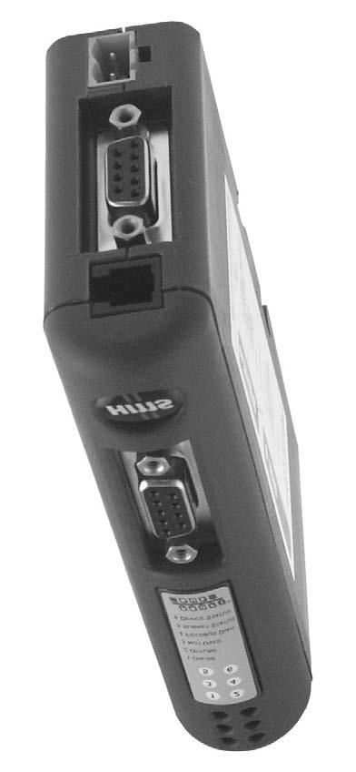

6 Installation 2.3 Connections and operating elements G09-RMx621ZZ xx-de Installation on DIN rail A - Snap ON B - Snap OFF G09-RMx621xx xx-001 6
 For connection to the PROFIBUS we recommend the use of an EN 50170 compliant 9-pole Sub-D plug with an integrated Bus termination resistance.")
7 Installation 2.5 Connections and terminal layout Connecting the RMx621 / FML621 with the PROFIBUS-coupler G09-RMx621ZZ xx-de-004! Note! The color indication is valid for the cable supplied. PROFIBUS DP connections (to the PROFIBUS-coupler) For connection to the PROFIBUS we recommend the use of an EN compliant 9-pole Sub-D plug with an integrated Bus termination resistance. G09-RMx621ZZ xx-xx-003 7
 5 GND Operational ground 6 VP Supply for the termination resistors 8 A-cable RxTx (-) 2.")
8 Installation 2.6 PROFIBUS-DP terminal layout Pin No. Signal Description Housing Screen Functional ground 3 B-cable RxTx (+) 5 GND Operational ground 6 VP Supply for the termination resistors 8 A-cable RxTx (-) 2.7 Bus address set-up The two selector switches used for the set up of the Bus address are available after carefully opening the front cover. G09-RMx621xx xx-000! Note! Using these selector switches Bus addresses within a range of 00 to 99 can freely set up. Only use valid addresses. 8
 of the RMx621/ FML621 the parameters for the RS485 (1) interface should be set up as Unit address to 1 and Baudrate to 38400.")

9 Commissioning 3 Commissioning 3.1 Set-up for the RMx621 / FML621 In the main menu Communication É RS485(1) of the RMx621/ FML621 the parameters for the RS485 (1) interface should be set up as Unit address to 1 and Baudrate to G09-RMx621xx de-001 How many process values are to be transmitted can be set up in the main menu Communication É PROFIBUS É Number, whereby the maximum number is limited to 48. In further steps each offset address can be allocated to the required process value using selection lists. G09-RMx621xx de-002! Note! For simple and easy further evaluation of the process values the list of offset addresses can be printed out using the ReadWin 2000 operating software.. When specifying the process values displayed with PROFIBUS DP, please note that the same process value can be set to more than one address. If a PROFIBUS coupler labeled "Rev.B" is used, device software version V should be used for RMC621 and device software version V for RMS621. PROFIBUS couplers labeled "Rev.B" have a fixed baudrate of 38,400 baud. Set the baudrate to 57,600 for devices before "Rev.B". 3.2 Set-up for the PROFIBUS-coupler The PROFIBUS-coupler is already set-up by the factory. Apart from the Bus addresses no further setup is required. A match to the Profibus-DP data transmission rate is done automatically. 9

10 Commissioning 3.3 Status display The 6 LEDs display the actual unit status and data exchange. G09-RMx621xx xx-003 LED Description Display Status Actions 1 ONLINE Green Off 2 OFFLINE Red Off 3 NOT USED PROFIBUS-coupler ready for operation PROFIBUS-coupler not ready for operation Check connector Check Profibus network 4 FIELDBUS DIAG Red flashing Configuration error Check PLC set-up Off No Bus error detected 5 SUBNET STATUS Green Data exchange running Green flashing Data exchange halted Check connection between Red Data exchange not possible PROFIBUS-coupler and the RMx621 / FML621; Check communication parameter in the RMx621 / FML621 Off Power supply failure Check the power supply 6 DEVICE STATUS Green Initialisation running Green flashing Red/Green flashing PROFIBUS-coupler operating Faulty set-up Unit defective Off Power supply failure Check the power supply 10
11 Data transmission 4 Data transmission 4.1 General In the RMx621 / FML621 various process values are calculated dependent on the preset applications and are then made available for read out. In addition to the calculated values the input values can also be read out from the RMx621 / FML Usable data construction Each process value takes up 5 Bytes in the process picture. The first 4 Bytes are compliant to an IEEE-754 (MSB first) 32-Bit floating point number 32-Bit floating point number (IEEE-754) Octet VZ (E) 2 7 (E) 2 6 (E) (E) 2 0 (M) 2-1 (M) 2-2 (M) (M) 2-8 (M) (M) 2-16 (M) 2-23 VZ = 0: Positive number VZ = 1: Negative number Number = -1 VZ (1 + M) 2 E 127 E = Exponent; M = Mantissa Example: 40 F h = b Value = ( ) = ( ) = = 7.5 The last Byte transmits the value s status: 80h = Valid value 81h = Valid value with alarm set point violation (linked to relay output) 10h = Faulty value (e.g. Cable open circuit) 00h = No value available (e.g. due to communication error in the sub-net)! Note! For calculated values (e.g. mass flow), the alarm condition of all the inputs deployed and the application are checked. If a "fault" is displayed for one of these variables, the calculated value is given the status "10h", i.e. invalid value. Example: Temp1 cable open circuit; Alarm type: fault => calculated mass flow (10h) Temp1 cable open circuit; Alarm type: notice => calculated mass flow (80h) The number of process values transmitted is laid down in the energy manager set-up, see Section 3.1. The minimum number is 1 process value (5 Byte), the maximum is 48 process values (240 Byte). 11


12 Data transmission 4.3 Units for the transmission of process values The units for the transmission of process values are specified in the Setup menu of the RMx621 / FML621. Choose Display units in order to use the units configured for display also for the transmission via PROFIBUS DP. Choose Default units to use the following standard units for the transmission: Volume flow l/s Temperature C Pressure Heat quantity Heat flow (power) Mass flow Corrected volume Flow sum Mass sum Corrected flow sum bar kj kw (kj/s) kg/s (N)l/s l kg (N)l Density kg/m 3 Enthalpy kj/kg 12

13 Installation in a Simatic S7 5 Installation in a Simatic S7 5.1 Network overview G09-RMx621xx-02-xx-xx-de GSD file EH_x153F.gsd Either install using Extras/install new GSD or copy the GSD- and BMP- files into the required directory of the Software STEP 7. e.g.: c:\...\siemens\step7\s7data\gsd c:\...\ Siemens\Step7\S7data\NSBMP The GSD-file is located on the Readwin 2000 CD-ROM supplied, in the directory \GSD\RMS621 RMC621 RMM621\ Example for Energy Manager G09-RMx621xx xx-xx

14 Installation in a Simatic S7 5.3 Projecting the RMx621 / FML621 as a slave Hardware configuration (e.g. Energy Manager RMS/RMC621): Pull out the Energymanager RMx621 unit from the hardware catalogue -> PROFIBUS DP -> further field units -> General in the PROFIBUS DP network Set the user addresses G09-RMx621xx-02-xx-xx-de-001 The GSD-File has two modules defined: Input (SPS) RMx621 É PROFIBUS master Config string AI: 5 bytes One numeric value + status 0x40, 0x84 4 AI: 20 bytes Four numeric values with status each 0x40, 0x93! Note! Assign as many modules to the individual slots as is necessary for the number of process values to match the number set in the energy manager. A maximum of 12 modules can be used here. The "4 AI: 20 Byte" module can be used instead of four individual "AI: 5 Byte" modules. The projected unit address must correspond with the actual set up hardware addresses. The address range of the process values must be uninterrupted. 14
15 Technical data 6 Technical data Dimensions: 120mm x 75mm x 27mm (height, depth, width) Power supply: 24V DC +/-10% Power consumption: PROFIBUS-DP Baud rate: Typ. 120mA, Max. 280mA 9.600, , , , , , 1.5M, 3M, 6M, 12M RS485 interface parameters: Baud rate 38400, 8 data bits, 1 stop bit, unit address 01 Ambient temperature: C Storage temperature: C Air humidity: %, no condensation Ingress protection: IP 20 Ground cable connection: Approvals: Grounded internally via the DIN rail UL - E
16 BA154R/09/en/ FM+SGML6.0 ProMoDo
RMx621. Appendix to the operating manual
 Appendix to the operating manual RMx621 DP-slave module ( PROFIBUS-coupler ) from V2.01.00 Connecting the RMx621 to PROFIBUS DP via the RS485 serial interface using the external module (HMS AnyBus Communicator
Appendix to the Operating Instructions RMx621 with ModBus Interface V Connection to ModBus-IDA System
 Operating Instructions Appendix to the Operating Instructions RMx621 with ModBus Interface V3.03.00 Connection to ModBus-IDA System BA231R/09/en/08.09 71027031 MS Word Endress+Hauser 2 Contents 1 General...
BA00216R/09/EN/ MS Word
 Operating Instructions Appendix to the Operating Instructions Energy Manager RMx621 with M-Bus interface V3.06.00 Connecting the Energy Manager to M-Bus system (two-wire bus in accordance with DIN EN 1434-3)
Operating Instructions RMx621
 BA00216R/09/EN/03.17 71355431 Valid as of FW version: 03.08.xx (device software) Products Solutions Services Operating Instructions Appendix to the Operating Instructions M-Bus interface V3.08.00: Connecting
Additional instructions Memograph M, RSG45 Advanced Data Manager
 BA01414R/09/EN/01.15 No.: 71302193 Firmware version ENU000A, V2.00.xx Products Solutions Services Additional instructions Memograph M, RSG45 Advanced Data Manager PROFIBUS DP slave Table of contents: 1
Table of Contents 1 ABOUT THIS DOCUMENT GENERAL COPYRIGHT INFORMATION TERMS ABOUT THE GATEWAY PRODUCT FUNCTIO
 DeviceNet/PROFIBUS-DP Adapter - User Manual REV 4.0 SiboTech Automation Co., Ltd. Technical Support: +86-21-5102 8348 E-mail:gt@sibotech.net Table of Contents 1 ABOUT THIS DOCUMENT...2 1.1 GENERAL... 2
PROFIBUS DP/CAN Gateway PCA-100. User Manual
 PCA-100 REV 4.0 SiboTech Automation Co., Ltd. Technical Support: 021-5102 8348 E-mail: support@sibotech.net Catalog 1 Introduction... 2 1.1 About This Instruction... 2 1.2 Copyright... 2 1.3 Related Products...
Operation Manual Profibus DP -Display HE 5120 P with digital I/O's
 Operation Manual Profibus DP -Display HE 510 P with digital I/O's "HESCH" Schröder GmbH Boschstraße 8 31535 Neustadt Telefon +49 (0) 503 / 9535-0 Telefax +49 (0) 503 / 9535-99 e-mail: info@hesch.de http://www.hesch.de
SCHMIDT Sensor interface PROFIBUS Instructions for use
 SCHMIDT Sensor interface PROFIBUS Instructions for use Table of contents 1 Important information... 3 2 Intended use... 4 3 Electrical connection... 4 4 Signalizations... 7 5 Startup... 9 6 Technical data...
INSTRUCTION MANUAL WCS-Interface Module, DeviceNet
 FACTORY AUTOMATION INSTRUCTION MANUAL WCS-Interface Module, DeviceNet WCS-DG210 Part. No. 202340 / DOCT-1305 / 11. june 2007 1 Working principle............................ 6 2 Installation and commissioning.................
Anybus X-gateway. PROFIBUS Master Interface NETWORK GUIDE SCM EN 1.0 ENGLISH
 Anybus X-gateway PROFIBUS Master Interface NETWORK GUIDE SCM-1202-104 EN 1.0 ENGLISH Important User Information Liability Every care has been taken in the preparation of this document. Please inform HMS
H 250 with PROFIBUS-PA signal converter ESK3-PA
 KROHNE 12/2000 7.02117.21.00 GR Supplement to Installation and Operating Instructions Variable area flowmeter H 250 with PROFIBUS-PA signal converter ESK3-PA Version: 1.02/00-06-29 Suitable for software
i-7550 PROFIBUS to RS-232/422/485 Converter User's Manual High Quality, Industrial Data Acquisition, and Control Products
 i-7550 PROFIBUS to RS-232/422/485 Converter User's Manual High Quality, Industrial Data Acquisition, and Control Products i-7550 PROFIBUS to RS-232/422/485 Converter User's Manual (Version 1.01) PAGE:1
UFC 400 Supplementary instructions
 UFC 400 Supplementary instructions Signal converter for ultrasonic flowmeters Description of PROFIBUS interface PROFIBUS PA: PROFIBUS device with MBP Physical Interface and PA Profile 3.02 (V2.2.3_ / 140430)
FC8x. Profibus Communication
 Title FC8x Profibus Communication SIEB & MEYER AG Auf dem Schmaarkamp 21 * D-21339 Lüneburg * (Germany) Telephone: +49-4131 - 203-0 * Telefax: +49-4131 - 203-2000 Email: documentation@sieb-meyer.de Internet:
VersaMax IP Input Module
 Module is used to accept digital input signals. Module Specifications Housing dimensions (width x height x depth) Connection style Operating temperature Storage temperature Operating/storage humidity 60mm
Modbus/ PROFIBUS DP Gateway PM-160
 Modbus/ PROFIBUS DP Gateway PM-160 REV 3.2 SiboTech Automation Co., Ltd. Technical Support: +86-21-5102 8348 E-mail: support@sibotech.net Table of Contents 1 About This Document... 3 1.1 General... 3 1.2
DVPPF02-SL PROFIBUS DP Slave Communication Module
 DVPPF02-SL PROFIBUS DP Slave Communication Module Operation Manual DVP-0155320-01 Warning This operation manual provides introduction on the functions, specifications, installation, basic operation, settings
L5353 Profibus-DP Communications Interface
 L5353 Profibus-DP Communications Interface Technical Manual HA470380 Issue 2 Copyright SSD Drives, Inc 2005 All rights strictly reserved. No part of this document may be stored in a retrieval system, or
PCM-Decoder HG A
 Device Description HG 17100-A PCM-Decoder HG 17100-A English, Revision 01 Dev. by: L.M. Date: 12.09.2013 Author(s): RAD / A.F. Götting KG, Celler Str. 5, D-31275 Lehrte - Röddensen (Germany), Tel.: +49
Operation manual. HDOM-Profibus-V0. More options please visit;www.veikong-electric.com
 Operation manual HDOM-Profibus-V0 More options please visit;www.veikong-electric.com Contents 1 Introduction... 1 1.1 Product description... 1 1.2 HDOM-Profibus-V0 label... 1 1.3 Technical specifications...
Date Revision Change(s) First version
 First version") Revision overview Revision overview Date Revision Change(s) 04.06.2015 0 First version Copyright 2015 Indu-Sol GmbH We reserve the right to amend this document without notice. We continuously work on further
Revision overview Revision overview Date Revision Change(s) 04.06.2015 0 First version Copyright 2015 Indu-Sol GmbH We reserve the right to amend this document without notice. We continuously work on further
CAN-Bridge. CAN Communications Module for CAN 2.0 A/B, CAN Layer AA01. Manual. Version 1/ from HW 1 & FW 1.00
 CAN-Bridge CAN Communications Module for CAN 2.0 A/B, CAN Layer 2 700-660-2AA01 Manual Version 1/26.01.2011 from HW 1 & FW 1.00 Manual order number 700-660-2AA01/en Systeme Helmholz GmbH Hannberger Weg
Expansion Module HZS 541-1S
 Expansion Module HZS 541-1S 12.10.2015 Page 1 System Description The external HZS 541-1S expansion module provides users of biomass heating systems with additional 230 V AC relay outputs, analog inputs
Device manual Profibus encoder. RM30xx RN30xx /00 06/2013
 Device manual Profibus encoder RM30xx RN30xx 706355/00 06/2013 Contents 1 Preliminary note................................................. 4 1.1 Symbols used...............................................
Fieldgate SFG500. Technical Information. Intelligent Ethernet/PROFIBUS gateway
 Technical Information Fieldgate Intelligent Ethernet/PROFIBUS gateway Application Fieldgate is a system component that provides an independent access route to a PROFIBUS network. It may be used in a variety
Date Revision Change(s) 29/07/ First version
 29/07/ First version") Revision overview Revision overview Date Revision Change(s) 29/07/2016 0 First version Copyright 2016 Indu-Sol GmbH We reserve the right to amend this document without notice. We continuously work on further
Revision overview Revision overview Date Revision Change(s) 29/07/2016 0 First version Copyright 2016 Indu-Sol GmbH We reserve the right to amend this document without notice. We continuously work on further
Date Revision Change(s) First version Firmware Update 1.5
 First version Firmware Update 1.5") Revision overview Revision overview Date Revision Change(s) 04.06.2015 0 First version 30.06.2016 1 Firmware Update 1.5 Copyright 2016 Indu-Sol GmbH We reserve the right to amend this document without
Revision overview Revision overview Date Revision Change(s) 04.06.2015 0 First version 30.06.2016 1 Firmware Update 1.5 Copyright 2016 Indu-Sol GmbH We reserve the right to amend this document without
Operating Manual UMB ISO Converter ISOCON Order Number: 8160.UISO
 Order Number: 8160.UISO Status: V3; 17.09.2010c G. Lufft Mess- und Regeltechnik GmbH, Fellbach, Germany 1 TABLE OF CONTENTS PLEASE READ BEFORE USE... 3 DESCRIPTION... 5 UMB ISO CONVERTER ISOCON... 6 CONFIGURATION...
Anybus Communicator STARTUP GUIDE. IIoT. SP en-us ENGLISH
 Anybus Communicator IIoT STARTUP GUIDE ENGLISH Important User Information Liability Every care has been taken in the preparation of this document. Please inform HMS Industrial Networks AB of any inaccuracies
Murdoch University Engineering Thesis. Appendix XII. Profibus PA System Configuration Instructions
 Appendix XII Profibus PA System Configuration Instructions Author: Hao Xu Page: p8 - p Last modified: // This is part of the Engineering Thesis WinCC SCADA System via Profibus & OPC by Hao Xu. 8 P a g
Catalog 1 Product Overview General Important User Information About the Gateway Function Features Tec
 PROFIBUS DP / Modbus TCP Gateway EP-321MP User Manual REV 1.2 Sibotech Automation Co., Ltd Technical Support: 021-5102 8348 E-mail:support@sibotech.net Catalog 1 Product Overview... 4 1.1 General...4 1.2
CAN 300 PRO, Communication Module
 90 Communication Modules CAN 300 PRO, Communication Module Layer 2, 11 Bit and 29 Bit (CAN 2.0 A/B) on the module DIP switch for adress + baud rate Micro Memory Card for saving a project (optional) USB
Supplementary instructions Sigma X control type with PROFIBUS
 Supplementary instructions Sigma X control type with PROFIBUS EN These operating instructions are only valid in combination with the "Operating instructions for diaphragm motor driven dosing pump Sigma
ST (6ES7132-6FD00-0BB1)
") SIMATIC ET 200SP Digital output module DQ 4x24..230VAC/2A ST (6ES7132-6FD00-0BB1) Manual Edition 02/2014 Answers for industry. DQ 4x24..230VAC/2A ST Preface Guide to documentation 1 SIMATIC ET 200SP DQ
SIMATIC ET 200SP Digital output module DQ 4x24..230VAC/2A ST (6ES7132-6FD00-0BB1) Manual Edition 02/2014 Answers for industry. DQ 4x24..230VAC/2A ST Preface Guide to documentation 1 SIMATIC ET 200SP DQ
Product Information Mixed. Configuration ET 200SP / ET 200AL SIMATIC. ET 200SP Product Information Mixed Configuration ET 200SP / ET 200AL.
 Product Information Mixed Configuration ET 200SP / ET 200AL SIMATIC ET 200SP Product Information Mixed Configuration ET 200SP / ET 200AL Product Information Preface Application planning 1 Mounting 2 Connection
The accessories described in this manual are of the highest quality, carefully designed and built in order to ensure excellent performance.
 INTRODUCTION Thank you for choosing our product. The accessories described in this manual are of the highest quality, carefully designed and built in order to ensure excellent performance. This manual
PROFI-5053 PROFIBUS Remote I/O Module Quick Start Guide
 Introduction PROFI-5053 PROFIBUS Remote I/O Module Quick Start Guide This user guide introduces the user how to implement the PROFI-5000 into their applications in a quick and easy way. Therefore, it only
SMART RELAY SRW 01 V4.0X
 Motors Automation Energy Transmission & Distribution Coatings SMART RELAY SRW 01 V4.0X Profibus DP Communication Manual Profibus DP Communication Manual Series: SRW 01 Firmware Version: V4.0X Language:
LB/FB8X09* / LB/FB8X05*
 GETTING STARTED Connecting Remote I/O Stations with Com Unit LB/FB8X09* / LB/FB8X05* to Siemens PLC (S7-300) via PROFIBUS 1 Contents 1. INTRODUCTION... 3 2. PREPARING FOR CONFIGURATION... 3 2.1. DOWNLOADING
ABB Drives. User s Manual. Modbus Adapter Module RMBA-01
 ABB Drives User s Manual Modbus Adapter Module RMBA-01 Modbus Adapter Module RMBA-01 User s Manual 3AFE 64498851 REV A EN EFFECTIVE: 1.3.2002 2002 ABB Oy. All Rights Reserved. Safety instructions Overview
Technical Manual. HA Issue 4. Copyright Parker SSD Drives, Inc 2008
 Technical Manual HA470380 Issue 4 Copyright Parker SSD Drives, Inc 2008 All rights strictly reserved. No part of this document may be stored in a retrieval system, or transmitted in any form or by any
Temposonics. R-Series Profibus. Absolute, Non-Contact Position Sensors. Temposonics RP and RH Stroke length mm
 Temposonics Absolute, Non-Contact Position Sensors R-Series Temposonics RP and RH Stroke length 25 7600 mm Advanced Communication offers Multi-Position Measurement Rugged industrial sensor Linear and absolute
RS485 MODBUS Module 6RO
 Version 2.0 12/02/2013 Manufactured for Thank you for choosing our product. This manual will help you with proper support and proper operation of the device. The information contained in this manual have
NMID. Remote control. SAPIM I/O number. SAPIM I/O number NBRN (RS485) ZM100. Relay, 24 VDC - + UO07 UI11 UI10 UI09 UI08 UI07 UI06 UI05 UI04 UI03 UI02
 ZM100. Relay, 24 VDC - + UO07 UI11 UI10 UI09 UI08 UI07 UI06 UI05 UI04 UI03 UI02") 1/8 NRK16/A, NRK16-B/A, (NRK16-T /A, NRK14-T /A, NRK16-WEB/A) Control and interlock devices with pre-programmed system-specific application modules The controllers may be used as stand-alone control and
1/8 NRK16/A, NRK16-B/A, (NRK16-T /A, NRK14-T /A, NRK16-WEB/A) Control and interlock devices with pre-programmed system-specific application modules The controllers may be used as stand-alone control and
An optional analog input module, Order no connected to a 6-pole system connector adds four more analog sensors to the device.
 Application: The analog input 4gang RMD processes measured-value data supplied by analog sensors. Four analog transducers in any combination can be connected to the input. The analog input 4gang RMD evaluates
Motortronics VirtualSCADA VS2-MT Communication Gateway VS2-MT User Manual Revision
 Motortronics VirtualSCADA VS2-MT Communication Gateway VS2-MT User Manual Revision 1.03.00 Motortronics / Phasetronics 1600 Sunshine Drive Clearwater, Florida 33765 Tel: 727-573-1819 Fax: 727-573-1803
I/O module (Expansion module)
") I/O module (Expansion module) Variomat Variomat Giga Reflexomat Servitec V2.00 02.02.2015 GB Operating manual Original operating manual English I/O module (Expansion module) Contents 02.02.2015 Contents
I/O module (Expansion module) Variomat Variomat Giga Reflexomat Servitec V2.00 02.02.2015 GB Operating manual Original operating manual English I/O module (Expansion module) Contents 02.02.2015 Contents
EL731 PROFIBUS INTERFACE
 Tel: +1-800-832-3873 E-mail: techline@littelfuse.com www.littelfuse.com/el731 EL731 PROFIBUS INTERFACE Revision 0-A-032816 Copyright 2016 Littelfuse Startco All rights reserved. Document Number: PM-1011-EN
IO1000. Type designation. Product description I/O module INSTALLATION MANUAL. Catalog no. from software version Document no I/O module 1.
 INSTALLATION MANUAL IO1000 Type designation Product description I/O module Catalog no. from software version Document no. 560-310 I/O module 1.0 jiqc10en1-b (1301) This document applies to the software
The output variables can be force-controlled from a coordinating control system.
 Produktname: 4-channel analog actuator Bauform: rail-mounted device Artikel-Nr.: 1022 00 ETS-Suchpfad: Gira Giersiepen / Output / Analog output 4fach / Analog actuator 4fach Scope of application: The analog
CVIC II - CVIL II - CVIR II - MULTICVIL II - Memory Mapping - Manual
 1/36 CVIC II - CVIL II - CVIR II - MULTICVIL II - Memory Mapping - Manual N - Copyright 2011, St Herblain France All rights reserved. Any unauthorized use or copying of the contents or part thereof is
While every effort was made to verify the following information, no warranty of accuracy or usability is expressed or implied.
 AG090115 How to configure SIMATIC STEP7 V5.5 to read cyclic data from Objective: To use Siemens SIMATC S7300 PLC to read data from MultiRanger/HydroRanger 200 HMI through SmartLinx PROFIBUS communication
GW-7553-CPM PROFIBUS/CANopen GATEWAY. User's Manual
 GW-7553-CPM PROFIBUS/CANopen GATEWAY User's Manual High Quality, Industrial Data Acquisition, and Control Products GW-7553-CPM PROFIBUS/CANopen GATEWAY User Manual (Version 1.00, Apr/2016) PAGE: 1 Warranty
PA ROUTERS. The following criteria can be applied when choosing the network transition:
 PA ROUTERS To create a smooth network transition between PROFIBUS DP and PROFIBUS PA, the SIMATIC product range offers two versions: the DP/PA coupler and the PA link. The following criteria can be applied
Date Revision Change(s) 10/10/ First version
 10/10/ First version") Revision overview Revision overview Date Revision Change(s) 10/10/2017 0 First version Copyright 2017 Indu-Sol GmbH We reserve the right to amend this document without notice. We continuously work on further
Revision overview Revision overview Date Revision Change(s) 10/10/2017 0 First version Copyright 2017 Indu-Sol GmbH We reserve the right to amend this document without notice. We continuously work on further
VPGate Manual PROFIBUS to serial
 VPGate Manual PROFIBUS to serial Important information Purpose of the Manual This user manual provides information how to work with the VPGate PROFIBUS to serial. Document Updates You can obtain constantly
ANTAL ELECTRONIC Field Bus and Communication Technology. Manual PDP2CL2. Version 3.08
 ANTAL ELECTRONIC Field Bus and Communication Technology Manual PDP2CL2 Version 3.08 ANTAL ELECTRONIC Höfles 4 91322 Gräfenberg Telephone (+49) 09192/9256-0 Fax (+49) 09192/9256-78 Important Notice Antal
IL CAN BK-TC-PAC. Extract from the online catalog. Order No.:
 Extract from the online catalog IL CAN BK-TC-PAC Order No.: 2718701 CANopen bus coupler, 24 V DC, bus interface 2 x 5-pos. TWIN- COMBICON connector, complete with accessories (connector and labeling field)
ILBPB24DO32. Inline Block IO Module for PROFIBUS With 32 Digital Outputs. AUTOMATIONWORX Data Sheet 6889_en_04. Description
 Inline Block IO Module for PROFIBUS With 32 Digital Outputs AUTOMATIONWORX Data Sheet 6889_en_04 Description PHOENIX CONTACT - 03/2007 & & ' ) The ILB PB 24 DO32 module is designed for use within a PROFIBUS
Universal Serial/PROFIBUS DP Gateway GT200-DP-RS User Manual V6.1 SST Automation
 GT200-DP-RS V6.1 SST Automation E-mail: SUPPORT@SSTCOMM.COM WWW.SSTCOMM.COM Catalog 1 About the Gateway...4 1.1 Product Function...4 1.2 Product Features... 4 1.3 Technical Specifications... 4 1.4 Related
Motors Automation Energy Transmission & Distribution Coatings. Profibus DP SRW 01. User s Manual
 Motors Automation Energy Transmission & Distribution Coatings Profibus DP SRW 01 User s Manual Profibus DP User s Manual Series: SRW 01 Firmware Version: V6.0X Language: English Document Number: 10000521541
RS485 MODBUS Module 8AO
 Version 1.3 12/02/2013 Manufactured for Thank you for choosing our product. This manual will help you with proper support and proper operation of the device. The information contained in this manual have
BB2 Profibus DP option
 BB2 Profibus DP option 2017-09-06 MANUS09/17 VER 1.03 Table of contents 1. Introduction... 3 2. A few words about this manual... 3 3. Fieldbus introduction... 3 Network Overview... 3 4. Unpacking... 4
Siemens Drives & PLCs
 Automation System S7-300: Getting Started CPU 31xC: Commissioning Introduction 1 Preparation 2 SIMATIC S7-300 Automation System S7-300: Getting Started CPU 31xC: Commissioning Learning units 3 Further
Serial PROFIBUS Interface
 Installation Manual Serial PROFIBUS Interface Version: EN-062016-2.3 Copyright 2016 Softing Industrial Automation GmbH Disclaimer of liability The information contained in these instructions corresponds
Dual Channel Monitor for Measurement of Speed and Ratio with SIL1 requirements Series D224.xx
 D224 Dual Channel Monitor for Measurement of Speed and Ratio with SIL1 requirements Series D224.xx D224 Front View KEY FEATURES SIL1 / IEC 61508:2010 compliant Dual Channel Speed and Ratio Monitor with
1. CP430, CP470, CP474, CP770 and CP774
 1. CP430, CP470, CP474, CP770 and CP774 1.1 Order data CPUs CP430, CP470, CP474, CP770 and CP774 CP430, CP470, CP770 CP474, CP774 Model number 7CP430.60-1 7CP470.60-2 7CP474.60-2 7CP770.60-1 7CP774.60-1
IL CAN BK-TC-PAC. Extract from the online catalog. Order No.:
 Extract from the online catalog IL CAN BK-TC-PAC Order No.: 2718701 CANopen bus coupler, 24 V DC, bus interface 2 x 5-pos. TWIN- COMBICON connector, complete with accessories (connector and labeling field)
IndraControl S67. Fieldbus coupler PROFINET
 Fieldbus coupler PROFINET Bosch Rexroth AG Electric Drives and Controls Documentation Instructions Technical data S67-PN-BK-DI8-M8 System data Interfaces Number of segments per station Total of all I/O
Installation and Operating Instructions. webremote
 Installation and Operating Instructions webremote 02/2012 PSG Plastic Service GmbH 1 Installations- und Bedienungsanleitung webremote Table of Contents 1 Typographical Conventions 2 webremote 2.1 Overview
General information. Engineering with. Supply voltage. Load voltage L+ Input current. Power losses. Memory. Work memory.
 Product data sheet SIMATIC S7-300, CPU 314C-2DP COMPACT CPU WITH MPI, 24 DI/16 DO, 4AI, 2AO, 1 PT100, 4 FAST COUNTERS (60 KHZ), INTEGRATED DP INTERFACE, INTEGRATED 24V DC POWER SUPPLY, 64 KBYTE WORKING
Linienkoppler S KNX. Line coupler S KNX. Line coupler S KNX Status: March 16 (Subject to change) Page 1 of 29
 Page 1 of 29") Linienkoppler S KNX Line coupler S KNX Line coupler S KNX 9070880 Status: March 16 (Subject to change) Page 1 of 29 KNX Contents Contents Page 1 General... 3 1.1 Using the product manual... 3 1.1.1 Structure
Linienkoppler S KNX Line coupler S KNX Line coupler S KNX 9070880 Status: March 16 (Subject to change) Page 1 of 29 KNX Contents Contents Page 1 General... 3 1.1 Using the product manual... 3 1.1.1 Structure
Operator Manual for Profibus
 PROCESS ANALYSERS SERVOPRO MultiExact Operator Manual for Profibus Part Number: Revision: Language: 05410007A 0 UK English This page intentionally blank LIST OF CONTENTS Section Page 1. DESCRIPTION AND
PROFIBUS Slave. X-gateway Interface Addendum. Doc: HMSI , Rev: Connecting Devices TM
 X-gateway Interface Addendum PROFIBUS Slave Connecting Devices TM HALMSTAD CHICAGO KARLSRUHE TOKYO BEIJING MILANO MULHOUSE COVENTRY PUNE COPENHAGEN HMS Industrial Networks Mailing address: Box 4126, 300
Gateway 1400 Reference Manual
 Profibus-DP Gateway 1400 Reference Manual Copyright All Rights Reserved. No part of this document may be copied, reproduced, republished, uploaded, posted, transmitted, distributed, stored in or introduced
User s Manual DX1000/DX1000N/DX2000 PROFIBUS-DP (/CP1) Communication Interface
 Communication Interface") User s Manual DX1000/DX1000N/DX2000 PROFIBUS-DP (/CP1) Communication Interface Yokogawa Electric Corporation 3rd Edition Thank you for purchasing Daqstation DX1000, DX1000N, or DX2000 (Hereafter, called
User s Manual DX1000/DX1000N/DX2000 PROFIBUS-DP (/CP1) Communication Interface Yokogawa Electric Corporation 3rd Edition Thank you for purchasing Daqstation DX1000, DX1000N, or DX2000 (Hereafter, called
SDM-8AO. Expansion Module 8 analog outputs. Manufactured for
 Version 1.0 16.05.2014 Manufactured for Thank you for choosing our product. This manual will help you with proper support and proper operation of the device. The information contained in this manual have
GRASSO SYSTEM CONTROL
 Control device for Packages and Chillers with screw compressors Product information 09.2002/ 2 638630_pi gsc gbr.doc Copyright GmbH Refrigeration Technology The contents of this documentation and the enclosed
AnyBus-PCI Profibus DPV1 Master
 AnyBus-PCI Profibus DPV1 Master Package Contents The AnyBus-PCI Profibus DPV1 Master package consists of the following items: Anybus-PCI Profibus DPV1 Master card This installation leaflet CD-ROM containing
FIELDBUS TECHNOLOGY ETHERNET- PROFIBUS- INTERFACE PB-XEPI F1144/ 03 INSTALLATION MANUAL
 FIELDBUS TECHNOLOGY ETHERNET- PROFIBUS- INTERFACE PB-XEPI INSTALLATION MANUAL F1144/ 03 2 Installation PB-XEPI D301144 0509 Content About this "Installation manual"...5 Intended use...5 Explanation of
PCAN-Router FD Universal, programmable Converter for CAN FD and CAN. User Manual. Document version ( )
") PCAN-Router FD Universal, programmable Converter for CAN FD and CAN User Manual Document version 1.0.1 (2017-01-27) Relevant products Product Name Model Part number PCAN-Router FD 2 D-Sub connectors IPEH-002214
PCAN-Router FD Universal, programmable Converter for CAN FD and CAN User Manual Document version 1.0.1 (2017-01-27) Relevant products Product Name Model Part number PCAN-Router FD 2 D-Sub connectors IPEH-002214
mipick Pick-by-Light System
 mipick Pick-by-Light System User Manual microsyst Systemelectronic GmbH Exclusive UK and Ireland Agent: Metrix Electronics Ltd tel: 0845 034 3234 www.metrix-electronics.com Index 1 SYSTEM OVERVIEW 4 2
General information. Supply voltage
 Data sheet SIMATIC S7-300, CPU 313C-2DP COMPACT CPU WITH MPI, 16 DI/16 DO, 3 FAST COUNTERS (30 KHZ), INTEGRATED DP INTERFACE, INTEGRATED 24V DC POWER SUPPLY, 128 KBYTE WORKING MEMORY, FRONT CONNECTOR (1
User Manual. Profibus DP Master to Crowcon Vortex 12 Ch. Generic. Formac Electronics Ltd. T:+44 (0) Oxford House F:+44 (0)
 Oxford House F:+44 (0)") User Manual Profibus DP Master to Crowcon Vortex 12 Ch. Generic Formac Electronics Ltd. T:+44 (0) 1225 837333 Oxford House F:+44 (0) 1225 430995 Combe Down e: info@formac.net Bath W:www.formac.net BA2
User Manual Profibus DP Master to Crowcon Vortex 12 Ch. Generic Formac Electronics Ltd. T:+44 (0) 1225 837333 Oxford House F:+44 (0) 1225 430995 Combe Down e: info@formac.net Bath W:www.formac.net BA2
Switched Mode Power Supply Operating manual PAP800
 Features: Switched mode power supply Wide output 0 144Vdc Analog control by an external 0 5Vdc Power failure alarm output Master-slave connection Powerfinn PAP series is a high power, lightweight, advanced
PAC BI-DP BIM and 8701-CA-BI Carrier
 June 2013 PAC8000 8507-BI-DP BIM and 8701-CA-BI Carrier PROFIBUS DP Bus Interface Module and Carrier The 8507-BI-DP Bus Interface Module (BIM) provides the communications link between the PAC8000 series
FLM DI 8 M12. Function. Fieldline Modular Device With Eight Digital Inputs. Data Sheet
 Fieldline Modular Device With Eight Digital Inputs Data Sheet 697000 02/2004 This data sheet is only valid in association with the FLS FLM SYS INST UM E user manual or the user manual for your bus system
PROFIBUS OPTION CARD FOR VLINX FIELDBUS GATEWAY
 VFG9000-PB-1012qsg Phone: (815) 433-5100 Fax: (815) 4334-5104 www.bb-elec.com PROFIBUS OPTION CARD FOR VLINX FIELDBUS GATEWAY ADDS PROFIBUS CONNECTIVITY TO THE FIELDBUS GATEWAY PROFIBUS SLAVE PROTOCOL
SDM-6RO. Expansion Module 6 relay outputs. Manufactured for
 Version 1.0 5.02.2014 Manufactured for Thank you for choosing our product. This manual will help you with proper support and proper operation of the device. The information contained in this manual have
This manual may not be reproduced in whole or in part by any means, without written permission of Accuenergy.
 Copyright 2008 V1.10 This manual may not be reproduced in whole or in part by any means, without written permission of Accuenergy. The information contained in this document is believed to be accurate
Documentation KM2042. Sixteen channel digital output module with D-Sub Connector. Version: Date:
 Documentation Sixteen channel digital output module with D-Sub Connector Version: Date: 2.0.0 2017-11-20 Table of contents Table of contents 1 Foreword... 5 1.1 Notes on the documentation... 5 1.2 Safety
PCAN-MicroMod Digital 1 & 2 Application-specific PCAN-MicroMod Motherboard. User Manual V1.10.0
 PCAN-MicroMod Digital 1 & 2 Application-specific PCAN-MicroMod Motherboard User Manual V1.10.0 Products taken into account Product Name Model Part number PCAN-MicroMod Digital 1 Including casing and PCAN-
CP ADVANCED. Function
 CP 343-1 ADVANCED Function The CP 343-1 Advanced independently handles data traffic over Industrial Ethernet. The module has its own processor and can be put into service directly using the unique preset
IQ SENSOR NET MIQ/(A-)MOD
MOD") Operating Manual IQ SENSOR NET Modbus RTU and RS 485 connection for the IQ SENSOR NET system2020 XT USB ba76021e01 01/2012 Note For the most recent version of the manual, please visit www.ysi.com. Contact
Operating Manual IQ SENSOR NET Modbus RTU and RS 485 connection for the IQ SENSOR NET system2020 XT USB ba76021e01 01/2012 Note For the most recent version of the manual, please visit www.ysi.com. Contact
MU110-6U. Analog output module 6 channel. User guide
 MU110-6U Analog output module 6 channel User guide MU110-6U_2016.12_0221_EN All rights reserved Subject to technical changes and misprints akytec GmbH Vahrenwalder Str. 269 A 30179 Hannover Тел.: +49 (0)
DN-DP PROFIBUS-DP / DeviceNet-Gateway
 PROFIBUS-DP / DeviceNet-Gateway Hardware Manual to Product C.2930.02 Hardware Manual Doc.-No.: C.2930.21 / Rev. 1.2 Page 1 of 17 esd electronic system design gmbh Vahrenwalder Str. 207 30165 Hannover Germany
RS485 MODBUS Module 8I8O
 Expansion Module 8 digital inputs, 8 digital outputs Version 2.2 12/01/2014 Manufactured for Thank you for choosing our product. This manual will help you with proper support and proper operation of the
Additional instructions Videographic recorder LINAX DR3000. PROFINET Device
 Additional instructions Videographic recorder LINAX DR3000 PROFINET Device Table of contents: 1 General information... 3 1.1 Scope of delivery... 3 1.2 Firmware history... 3 1.3 Connections... 4 1.3.1
User Manual AnyBus Communicator for Profibus
 User Manual AnyBus Communicator for Profibus Rev. 2.02 HMS Industrial Networks AB Germany Japan Sweden U.S.A +49-721 - 96472-0 +81-45 - 478-5340 +46-35 - 17 29 20 +1-773 - 404-3486 sales-ge@hms-networks.com