JUNE 2009 EME201AEE. Guide SUPPOR
|
|
|
- Beatrix Matthews
- 6 years ago
- Views:
Transcription


1 JUNE 2009 EME201AEE ServMon xb Environmental Monitoring System System Administrator s Guide SUPPOR RT FREE technical support

2 ServMon xb ServMon xb is a remote environmental monitoring system to increase the security of your facilities and reduce unforeseen downtimes of your equipment. Its modular conception allows to monitor many sensors and trigger emergency actions like individual control of power outlets and alert sending via SNMP traps, or Syslog messages. This product carries the CE mark to indicate compliance with the European Directive on Electromagnetic Compatibility (89/336/EEC). It has been tested to EN55024:1998 and EN55022:1998. Edition June 2009
3 Environmental monitoring system Contents Safety instructions: DESCRIPTION Diagram Package list Option INSTALLATION CONFIGURATION Configuration through the LAN using the Finder program Configuration through an RS232 Terminal connection Configuration through the LAN using a standard Browser General / IP configuration General / System time General / SMTP General / SNMP General / Tools Settings / Accounts Settings / Groups Settings / Peripherals Settings / Peripherals - devices labelling Settings / Peripherals - epowerswitch settings Settings / Peripherals - Sensors settings Settings / Peripherals - Digital Input settings Digital Input Modules Temperature and proximity sensors Push Button settings Settings / Peripherals - AC Current Probe settings Settings / Peripherals - Energy Meter settings Settings / Rules Settings / Rules / Schedule Rule Settings / Rules / Ping Monitoring Rule Settings / Rules / Scan Monitoring Rule Settings / Rules / Power Supply Monitoring Rule Settings / Rules / Digital Input Monitoring Rule Settings / Rules / Analog Input Monitoring Rule Misc / Control Panel Misc / Rule Panel Misc / Log Misc / Log Settings POWER OUTLET CONTROL AND PERIPHERALS STATUS ANNEXES Ping and Scan Methods Technical Data Commonly used Ports Syslog Messages: Severity Level Definitions
4 Environmental monitoring system Safety instructions: to read before use! NOTE The ServMon xb Remote Monitoring System and all its peripheral components can only be installed by qualified people with the following installation and use instructions. The manufacturer disclaims all responsibility in case of a bad use of the ServMon xb device and its peripheral components and particularly any use with equipments that may cause personal injury or material damage. The power adapter of the ServMon xb is designed to be installed on a dedicated circuit that must have a circuit breaker or fuse protection. The electrical power socket used to plug the power adapter of the ServMon xb must be close to the ServMon xb device and easily accessible. Check that the power adapter, plug and socket are in good condition. If power switches, Energy Meter or Current Probe devices are connected to the ServMon xb, always plug them into properly grounded power sockets (two poles plus ground). The ServMon xb is intended for indoor use only. Do NOT install them in an area where excessive moisture or heat is present. Always disconnect the power adapter of the ServMon xb if you want to intervene on the ServMon xb or on the equipments connected to the ServMon xb. Do NOT attempt to disassemble the ServMon xb or any of its peripheral components, they contain potentially hazardous voltages. The ServMon xb and its peripheral components contain no user serviceable parts and repairs are to be performed by factory trained service personnel only. Always use a shielded cable for the Ethernet connection. 2

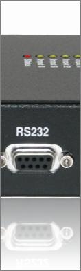
5 Environmental monitoring system 1. DESCRIPTION ServMon xb is a remote environmental monitoring system to increase the security of your facilities and reduce unforeseen downtimes of your equipment. Its modular conception allows to monitor many sensors and trigger emergency actions like individual control of power outlets and alert sending via SNMP traps, or Syslog messages 1.1 Diagram Front side 10/100 (RJ45 Connector) Network connection 10/100 Mbits/sec Link (LED): - off = network connection not detected - on = network connection detected - flashing = the device is sending or receiving data over this port 100 (LED): - off = 10 Mbits/sec connection - on = 100 Mbits/sec connection RS232 (SUB-D 9F Connector) Serial port RS232 for Terminal connexion Pinout: 2 = TxD, 3 = RxD, 5 = Gnd Back 12 VDC Power input B Optional second power supply of the ServMon xb The Web server can be powered either by Power Input A or Power Input B. I/O Dry contacts In1 to In4 4 digital inputs for dry contact xbus 1 to 4 (RJ45 Connector) Connection for all xbus peripherals Maximal TOTAL line length: 200 meters 12 VDC Power input A First power supply of the ServMon xb The Web server can be powered either by Power Input A or Power Input B. Top Side LEDs Power A: - green, lights up when power applied on power input A (on front side) Power B: - green, lights up when power applied on power input B (on front side) Input 1: - yellow, lights up when digital input 1 closed (on back side) Input 2: - yellow, lights up when digital input 2 closed (on back side) Input 3: - yellow, lights up when digital input 3 closed (on back side) Input 4: - yellow, lights up when digital input 4 closed (on back side) Status: - green, on, ServMon xb software is started - green/red flashing, ServMon xb is initializing 3


6 Environmental monitoring system 1.2. Package list The following items are included: 1 x ServMon xb device with cabinet mounting kit 1 x 19" rack mount kit, ref. RMK-D, 1 x power adapter 12 VDC 1 x RJ45 M/M cable, 2 Meters 1 x serial cable SUB-D 9 points M/F, 1.80 Meters 1 x CD ROM 1 x quick installation guide 1.3 Option The following option can be ordered separately: power adapter 12 VDC for redundant power supply, ref. PA 12VDC 4
7 Environmental monitoring system 2. INSTALLATION Connect the ServMon xb to your Local Area Network. Power-up the ServMon xb using the provided power adapter (you can use either the Power Input A on the front panel or the Power Input B on the back panel of the device). Starting needs approximately 30 seconds. During this time, the status LED on the top of the case flashes red/green. During all this time you cannot login. 5


 to configure the network parameters.")
8 Environm mental monitoring system 3. CONFIGURATION To use the ServMon xb on your network, you must first configure network administrator for the parameters to use. its network parameters. Ask your There are the three following methods to configure the network parameters of the ServMon xb: 3.1. Configuration through the LAN using the Finder program It is the simplest and fastest configuration method if you use Windows as operating system. It allows to configure your ServMon xb through your local network even if its network parameters are not compatible with those of your PC. 1. Start the Finder.exe program contained on the CD-ROM. 2. Open the File menu and choose SCAN (or click on the first left button in the tool bar) to discover the ServMon xb connected on your LAN. 3. Open the File menu and choose CONFIGURE (or click on the second left button in the tool bar) to configure the network parameters. This page enables to define all IP parameters of the ServMon xb device and displays the version of the Firmware. The HTTP protocol is enabled and the Finder program is authorized at factory settings.!!! To achieve the highest security level we suggest to disable the configuration using the Finder program after the first installation. 6
9 Environme ental monitoring system DHCP: Check this box is you want to obtain the IP address, the subnet mask and the default gateway for your ServMon xb via DHCP. Use of DHCP (Dynamic Host Configurationn Protocol) requires a DHCP host to be set up on the network. IP Address: IP addresss of the ServMon xb, default is Subnet Mask: Subnet Mask of the ServMon xb, default is Gateway: Generally the address of your router, default is blank. DNS 1: Primary DNS (Domain Name Server), default is blank. DNS 2: Secondary DNS, default is blank. Version: Firmware version of the ServMon xb Finder authorized: The Network parameters of the ServMon xb can be configured through a Local Area Network using the provided Finder Program. It is a simple and fast configuration method if you use Windows as operating system.!!! The Finder Program is enabled as default value. For security reasons we suggest to disable the Finder program after the first configuration. HTTP / HTTPS Access: These options enable to choose between the standard HTTP and the HTTP over SSL protocol. HTTPS encrypts and decrypts the page requests and page information between the client browser and the web server of the ServMon xb using a Secure Socket Layer (SSL). A URL beginning with HTTPS indicates that the connection is encrypted using SSL. SSL transactions are negotiated by means of a Keybased encryption algorithm between your browser and the web server of your ServMon xb. The HTTP protocol is enabled as default value. HTTP Port Number: Port number: default is 80 (HTTP). Standard HTTP port is 80. Standard HTTPS port is
10 Environmental monitoring system 3.2. Configuration through an RS232 Terminal connection 1. Use the provided RS232 cable to connect the ServMon xb to an available serial port of your PC. 2. Run a Terminal program such as Windows HyperTerminal. 3. Configure the appropriate serial 9.600, n, 8, 1 and no flow control. 4. On your computer, press <ENTER> until the menu appears on your screen. 5. Press the M on your keyboard and follow the menu to configure the network parameters of your ServMon xb. NETWORK INTERFACE PARAMETERS: Should this target obtain IP settings from the network?[n] Static IP address [ ]? Subnet Mask IP address [ ]? Gateway IP address [ ]? Primary DNS Server IP address [ ]? Secondary DNS Server IP address [ ]? MISCELLANEOUS: Finder program enabled?[y] Configuration menu 8
11 Environme ental monitoring system 3.3. Configuration through the LAN using a standard Browser During the first installation, change temporarily the network settings of your PC according to the default network settings of the ServMon xb. Factory network settings of the ServMon xb: IP Address: Port: 80 Gateway: Default factory protocol is HTTP!!! 1. Open your Web browser and type following IP address: 2. Enter the administrator name and password (default for both = admin) 3. The home page appears, allowing you to configure all settings of your ServMon xb. 9


12 Environmental monitoring system General / IP configuration This page enables you to define all the IP parameters of the ServMon xb Remote Monitoring System. DHCP Client enabled: Check this box is you want to obtain the IP address, the subnet mask and the default gateway for your ServMon xb via DHCP. Factory default setting for this option is disabled. Use of DHCP (Dynamic Host Configurationn Protocol) requires a DHCP host to be set up on the network. IP Address: IP addresss of the ServMon xb, default is If you use the https protocol and change the IP address, the system needs to compute new SSL keys. This operation takes several minutes and the LED marked "Status" on the case blinks 3 times repeatedly during all the process. During all this time, you cannot login. Subnet Mask: Subnet Mask of the ServMon xb, default is Default Gateway: Generally the address of your router, default is blank. Primary DNS Address: Primary DNS (Domain Name Server), default is blank Secondary DNS Address: Secondary DNS, default is blank Finder Program enabled: The Network parameters of the ServMon xb can also be configured through a Local Area Network using the provided Finder Program. It is a very simple and fast configuration method if you use Windows as operating system. The Finder Program is enabled as default value.!!!for security reasons we suggest to disable the Finder program after the first configuration. HTTP / HTTPS Access: This option enables to choose between the standard HTTP and the HTTP over SSL protocol. HTTPS encrypts and decrypts the page requests and page information between the client browser and the web server of the ServMon xb using a Secure Socket Layer (SSL). A URL beginningg with HTTPS indicates that the connection is encrypted using SSL. SSL transactions are negotiated by means of a Key-based encryptionn algorithm between your browser and the web server of your ServMon xb. The HTTP Protocol is enabled as default value.!!!to achieve the highest security level we suggest to choose the HTTPS protocol. 10
13 Environmental monitoring system HTTP Port: Port number: default is 80 (HTTP). Standard HTTP port is 80. Standard HTTPS port is 443. LOGOUT: Click "Logout" at the bottom of the page to exit the session without saving changes. DISCARD CHANGES: Click "Discard Changes" at the bottom of the page to discard all the changes you have made on this page. APPLY CHANGES: Click "Apply Changes" at the bottom of the page to save changes. 11


14 Environm mental monitoring system General / System time The system time of the ServMon xb is used for synchronizing scheduling actions and to timestamp SNMP traps, Syslog information, s and internal logs. The system time can be set manually with the browser time of the connected computer or can be automatically synchronized with one or two NTP timeservers. Current System Time: This field shows the current system time of the ServMon xb. As the system time is displayed through the browser, a small difference (1 to 2 sec) can appear as compared to the exact hour. The system time is nevertheless correct. Use Browser Time: If you want to set the system time using the current Browser time of your PC, select this option and click on the "Set System Time" button. Use NTP Server: If you want to set the system time using an NTP timeserver, select this option, choose a refresh interval and enter the IP address of the timeserver you wish to use in the "Primary" field. The address of a second timeserverr can be specified in the "Secondary" field. The secondary timeserver is optional and is used only if the primary timeserver is not available. You can enter either the hostname (in that case you must have specified a DNS serverr on the IP configuration page) or the IP address of an NTP server. NTP uses port 123/UDP. Time Zone: Set the time zone corresponding to your location. The system clock will subsequently show local time. Without setting this, the system clock will show UTC/GMT time. Setting a time zone is only relevant if you are synchronizing with an NTP server. Daylight Saving Time: If you want to set Daylight Saving dates, check this box and specify the date you want to use. LOGOUT: Click "Logout" at the bottom of the page to exit the session without saving changes. DISCARD CHANGES: Click "Discard Changes" at the bottom of the page to discard all the changes you have made on this page. APPLY CHANGES: Click "Apply Changes" at the bottom of the page to save changes. 12

 or the IP address of an NTP server. NTP uses port 123/UDP.")
15 Environme ental monitoring system General / SMTP You can setup the ServMon xb to send the logs to an account and report all activities triggered by the rules defined by the administrator. To send s, you will need a SMTP server on the network and you will have to configure the following parameters: SMTP enabled: Check this box if you want the ServMon xb to be able to send s. SMTP Server Address: In this field, enter the address of the server you want to use. You can enter either the hostname (in that case you must have specified a DNS serverr on the IP configuration page) or the IP address of an NTP server. NTP uses port 123/UDP. SMTP Port: In this field, enter the Port Number you want to use, default and usual port is 25. From ( Address): In this field, enter the address that ServMon xb messages will appear to come from. The name can be from 1 to 64 characters long, and can contain alphanumeric characters. This should be a valid address (generally servers reject messages that don't have a valid from address). Example: LOGOUT: Click "Logout" at the bottom of the page to exit the session without saving changes. DISCARD CHANGES: Click "Discard Changes" at the bottom of the page to discard all the changes you have made on this page. APPLY CHANGES: Click "Apply Changes" at the bottom of the page to save changes. 13
 agent, which enables you to manage the ServMon xb through SNMP-based network management systems.")

16 Environm mental monitoring system General / SNMP The ServMon xb provides a built-in SNMP (Simple Network Management Protocol) agent, which enables you to manage the ServMon xb through SNMP-based network management systems. The ServMon xb MIB file enables to remotely read out the status of all power outlets and the values of all sensors (temperature, humidity, ambient light). It also enables to control individually all power outlets and all groups of power outlets. The MIB file is stored on the ServMon xb and can be downloaded from the General / Tools Page. SNMP enabled: Check this box if you want to enable the SNMP protocol. Contact: In this field, enter the name you want to give to the Contact field. The name can be from 1 to 64 characters long, and can contain alphanumeric characters. Default name is "contact". Name: In this field, enter the name you want to give to the Name field. The name can be from 1 to 64 characters long, and can contain alphanumeric characters. Default name is "name". Location: In this field, enter the name you want to give to the Location field. The name can be from 1 to 64 characters long, and can contain alphanumeric characters. Default name is "location". Read Community: In this field, enter the name you want to give to the Read Community field. The name can be from 1 to 64 characters long, and can contain alphanumeric characters. Default name is "public". Write Community: Check this box if you want to be able to control the power outlets through a MIB browser. In the following field, enter the name you want to give to the Write Community. The name can be from 1 to 64 characters long, and can contain alphanumeric characters. Default name is "private". Trap Community: Check this box if you want to configure the ServMon xb SNMP agent to send traps to a community. In the following field, enter the name you want to give to the Trap Community. The name can be from 1 to 64 characters long, and can contain alphanumeric characters. Default name is "trap". Trap Destination 1: Check this box and enter the primary SNMP Server address the traps will be sent to. Trap Destination 2: Check this box and enter the secondary SNMP Server address the traps will be sent to. LOGOUT: Click "Logout" at the bottom of the page to exit the session without saving changes. DISCARD CHANGES: Click "Discard Changes" at the bottom of the page to discard all the changes you have made on this page. APPLY CHANGES: Click "Apply Changes" at the bottom of the page to save changes. 14

17 Environme ental monitoring system General / Tools This page enables you to: - downloadd and save the current settings of your ServMon xb on your PC - upload an existing configuration file to your ServMon xb - restore the factory settings - downloadd the ServMon xb MIB file on your PC. Save: Click this button to save the current system settings onto your local hard drive. Load: Click this button and select a settings file you want to download to the ServMon xb. Restore: Click this button if you want to restore the factory default settings. Save MIB: Click this button if you want to download the ServMon xb MIB file onto your local hard drive. LOGOUT: Click "Logout" at the bottom of the page to exit the session without saving changes. 15


18 Environm mental monitoring system Settings / Accounts This page is used to create, activate, deactivate, modify and delete up to 255 accounts. - To activate or deactivate an account, check or uncheck the corresponding checkbox. - To modify an account, click on "Edit" next to the corresponding account. - To deletee an existing account, click on "Delete" next to the corresponding account. - To createe an account, click on "Add a New Account" on the right side of the page. A new page appears, allowing you to set all the parameters of the account. User Name: In this field, enter the name you want to give to the user. The name can be from 1 to 32 characters long, and can contain alphanumeric characters. Password: In this field, enter the password you want to give to the user. The password can be from 4 to 32 characters long, and can contain alphanumeric characters. Confirm Password: In this field, enter the password again. 16
19 Environmental monitoring system Groups: This field is used to add or remove groups to the current account. To add Groups to the current account, press the Ctrl key and click on the displayed Groups. The selected Groups are marked dark blue and their IDs are listed at the right side of the Groups field. Device: In this drop-down list, choose a device from which you want to add Inputs or Outputs to the current account. Inputs/Outputs: This field is used to add/remove Inputs or Outputs to/from the current account. To add Inputs or Outputs to the current account, press the Ctrl key and click on the Inputs/Outputs of the device selected in the previous field. The selected Inputs/Outputs are marked dark blue and their IDs are listed at the right side of the Input/Output field. The ServMon xb supports number of peripherals which are clearly identified by specific ID Codes. LOGOUT: Click "Logout" at the bottom of the page to exit the session without saving changes. DISCARD CHANGES: Click "Discard Changes" at the bottom of the page to discard all the changes you have made on this page. APPLY CHANGES: Click "Apply Changes" at the bottom of the page to save changes. 17


20 Environm mental monitoring system Settings / Groups This page is used to create, modify and delete groups of power outlets which can be controlled by the ServMon xb. This functionality is particularly useful if you have to control the power supply of devices using redundant power supplies. You can create groups including several power outlets distributed on several epowerswitch 8XS devices. - To deletee an existing group, click on "Delete" of the corresponding device. - To add or remove power outlets to/from an existing group, click on "Edit" of the corresponding device. - To deactivate a Group, uncheck the box "Activated" of the corresponding group. - To add a new group, click on "Add a New Group" on the right side of the page. A new page appears, allowing you to set all parameters of the group. Group Id: The ServMon xb automatically creates an ID Code to clearly identify each group of Power Outlets. All the ID Codes used to identify groups start with the letter "G". Group Name: In this field, enter the name you want to give to the selected group. The name can be from 1 to 32 characters long, and can contain alphanumeric characters. Device: In this drop-down list, choose a Power Switch from which you want to add power outlets to the selected group. 18
21 Environmental monitoring system Power Outlets: This field is used to add and remove power outlets to/from the group. - To add power outlets to the group, press the Ctrl key and click on the power outlets of the Power Switch selected in the field above. The selected power outlets are marked dark blue and their names are listed at the right of the field "Power Outlets". - To remove a power outlet from the group, press the Ctrl key and click on the power outlet you wish to remove. LOGOUT: Click "Logout" at the bottom of the page to exit the session without saving changes. DISCARD CHANGES: Click "Discard Changes" at the bottom of the page to discard all the changes you have made on this page. APPLY CHANGES: Click "Apply Changes" at the bottom of the page to save changes. 19

 16 x Digital Input Modules (with 16 digital inputs) or 16 x push buttons or 16 x IR")
22 Environmental monitoring system Settings / Peripherals The Peripherals page is used to enable and configure the xbus peripherals which have been connected to the ServMon xb. This page is also very useful to give an overview of all the peripherals which are or have been connected to the ServMon xb. Following xbus peripherals can be connected to the ServMon xb Environmental Monitoring System: 16 x Secure Power Switch Satellite (8-Port) or Power Switch Satellite (1-Port) 16 x EnergyMeter for real-time power consumption measuring 16 x current probes 32 x sensors (temperature, humidity and ambient light) 16 x Digital Input Modules (with 16 digital inputs) or 16 x push buttons or 16 x IR proximity sensors any xbus Extenders any xbus Optocouplers You can connect an xbus peripheral to each of the 4 connectors located on the back of the ServMon xb or behind an xbus peripheral already connected to the ServMon xb (Daisy Chain Connection). Connecting an xbus peripheral to the ServMon xb: 1. Set the dip switches of the xbus peripheral so that the selected I/O addresss does not conflict with another peripheral already connected to the xbus (see user's guide of the corresponding peripheral). - Do NOT connect the xbus cable (and the power cable if need be) before setting its DIP switches - Do NOT use the same address for two different xbus peripherals 2. Using of the a standard RJ45 Network cable, connect the xbus peripheral to an xbus connector on the back ServMon xb or behind an xbus peripheral already connected to the ServMon xb. After connecting an xbus peripheral, you MUST enablee it in the Peripherals Page: 1. Open your browser and log in to the Administrator's Configuration Page (default: 2. Enter the administrator name and password (default for both = admin). => The home page appears. 3. Click on the Settings and then on the Peripherals Tab. If the peripheral is properly connected to the ServMon xb it will be automatically recognized and displayed on this page after a delay of 1 to 60 seconds. In this case, the colour of the corresponding Edit and Info symbol is red. The Peripheral page is not automatically refreshed, so you need to refresh it by clicking the peripheral TAB again (or push [F5] or press <CTRL-R> on your keyboard if you use Internet Explorer or Mozilla Firefox). 20


23 Environmental monitoring system Problem / Troubleshooting If you choose any setting that is already in use by another xbus peripheral connected to the ServMon xb, an address conflict occurs and the corresponding Edit and Info symbol of the previous connected peripheral will be replaced by a yellow warning triangle. In that case, disconnect your last connected peripheral, removee its power cable if need be, change the DIP switch settings to solve the address conflict and reconnect the peripheral. If the conflict is solved, all connected peripherals will appear on the Peripherals page and their Edit and Info Symbol will be red. The yellow warning triangle is also displayed to point out that a longer be reached (for instance if a cable is disconnected). connected xbus peripheral can no The Peripheral page is not automatically efreshed, so you need to refresh it by clicking the peripheral TAB again (or push [F5] or press <CTRL-R> on your keyboard if you use Internet Explorerr or Mozilla Firefox). The Peripherals page is used to configure all peripherals connected to the ServMon xb. - To activate a peripheral, check the box "Activated" of the correspondin ng device. - To deactivate a peripheral, uncheck the box " Activated" of the corresponding device. Even if the device remains physically connected to the ServMon xb, it will no longer be accessible by its authorized users. The ServMon xb cannot be deactivated. - To remove a peripheral, click on the corresponding Delete button. A peripheral cannot be deleted if it belongs to a group or a rule. In that case, you will first have to deletee it from the group or the rule. - To know the Firmware version of a device, click on the corresponding Info button. - To configure or modify the settings of a device, click on the corresponding "Edit" button. 21

24 Environm mental monitoring system Settings / Peripherals - devices labelling This page enables to label both power supply inputs, the 4 digital inputs located on the back of the ServMon xb and all connected devices. Names of up to 32 alphanumeric characters in length are supported and appear in log files, Syslog messages, SNMP traps and s to avoid confusions. Procedure: 1. Open you browserr and log in to the Administrator's Page, (ex. // /sysadmin.htm). 2. Enter the administrator name and password (default for both = admin). The home page appears. 3. Click on the Settings Tab and then on the Périphrasa Tab. Following new page appears, allowing you to define the labels. ID: The ServMon xb automatically creates an ID Code to clearly identify each device and each input. EMS0 identifies the ServMon xb PW followed by A or B identifies power supply input A and B of the ServMon xb DI followed by 1 to 4 identifies the Digital Inputs of the ServMon xb DIM followed by a number identifies the Digital Input Modules S followed by a number identifies the power switches T followed by a number identifies the temperature sensors TH followed by a number identifies the temperature and humidity sensors TA followed by a number identifies the temperature and ambient light sensorss TP followed by a number identifies the temperature and proximity sensors PB followed by a number identifies the push buttons CB followed by a number identifies the current probes EM followed by a number identifies the energy meters Name: In this field, enter the name you want to give to the selected device and its analog or digital inputs, power supply or Digital Input. The name can be from 1 to 32 characters long, and can contain alphanumeric characters. 22
25 Environmental monitoring system LOGOUT: Click "Logout" at the bottom of the page to exit the session without saving changes. DISCARD CHANGES: Click "Discard Changes" at the bottom of the page to discard all the changes you have made on this page. APPLY CHANGES: Click "Apply Changes" at the bottom of the page to save changes. 23
26 Environm mental monitoring system Settings / Peripherals - epowerswitch settings Up to 16 Power Switches 8-Port or Power Switches 1-Port can be attached to the ServMon xb to turn electrical devices on and off as well as reboot them remotely. You can connect a Power Switch 1-port or 8-port to each of the 4 connectors located on the back of the ServMon xb or behind an xbus peripheral already connected to the ServMon xb (Daisy Chain Connection). To connect a Power Switch to the ServMon xb, use following procedure: 1. Set the dip switches of the Power Switch so that the selected I/O address another Power Switch already installed (see user's guide of the corresponding does not conflict with Power Switch). - Do NOT connect the xbus cable and the power cable before setting its DIP switches, - Do NOT use the same address for two different Power Switch devices. 2. Using a standard RJ45 network cable, connect the Power Switch to an xbus connector on the back of the ServMon xb or behind another xbus peripheral already connected to the ServMon xb. 3. Connect the power cable(s) to your Power Switch device. To configure the Power Switch, use following Log in procedure: 1. Open you browserr and log in to the Administrator's Configuration Page, (ex Enter the administrator name and password (default for both = admin). The home page appears. 3. Click on the Settings and then on the Peripherals Tab. If the Power Switch is properly connected to the ServMon xb it will be automatically recognized and displayed on this page after a delay of up to 60 seconds. In this case, the colour of the corresponding Edit and Info symbol is red. The Peripheral page is not automatically refreshed, so you need to refresh it by clicking the peripheral TAB again (or push [F5] or press <CTRL-R> on your keyboard if you use Internet Explorer or Mozilla Firefox). Problem / Troubleshooting If you choose any setting that is already in use by another Power Switch connected to the ServMon xb, a conflict occurs and the corresponding Edit and Info symbol of the previous connected Power Switch will be changed to black. In that case, disconnect your last connected Power Switch, remove its power cable, change the DIP switch settings to solve the address conflict and reconnect the Power Switch again. If the conflict is solved, all connected Power Switches will now appear on the Peripherals page and their Edit and Info Symbol will be red. The Peripheral page is not automatically efreshed, so you need to refresh it by clicking the peripheral TAB again (or push [F5] or press <CTRL-R> on your keyboard if you use Internet Explorerr or Mozilla Firefox). 24

 and its")


27 Environme ental monitoring system To configure or modify the settings of the connected Power Switch device, click on the corresponding "Edit" button in the Peripherals page. A new page appears, allowing you to set all the parameters of the Power Switch device. ID: The ServMon xb automatically creates an ID Code to clearly identify each connected Power Switch, its power input(s) and its power outlet(s). S followed by a number between 1 and 16 identifies the Power Switch unit, PW followed by A or B identifies power supply input A and B of each Power Switch, followed by 1 to 8 identifies the Power outlet output, Name: In this field, enter the name you want to give to the selected Power Switch. The name can be from 1 to 32 characters long and can contain alphanumeric characters. Power Supplies: In this field, enter the name you want to give to the two power input 1 and 2. The name can be from 1 to 32 characters long and can containn alphanumeric characters. Power Outlets: In this field, enter the name you want to give to each power outlet of the Power Switch. The name can be from 1 to 32 characters long and can contain alphanumeric characters. Default Power-Up: In the drop-down lists, choose for each power outlet the default status to apply after power-up. You can choose between: - "On" if you want the corresponding power outlet to be always switched On after power-up. - "Off" if you want the corresponding power outlet to be always switched Off after power-up. - "Last Status" if you want that the corresponding power outlet takes again the state it was in before power failure. Power up delay: In this field, enter the power up delay you want to define for each power outlet. Power up delay means the delay before the power outlet will take the defined status after power up. The delay can be set between 1 and seconds, the value 0 means that no delay has to be applied after power up. Function delay: In this field, enter the delay you want to define before the execution of a function (for example Restart function of an outlet). LOGOUT: Click "Logout" at the bottom of the page to exit the session without saving changes. DISCARD CHANGES: Click "Discard Changes" at the bottom of the page to discard all the changes you have made on this page. APPLY CHANGES: Click "Apply Changes" at the bottom of the page to save changes. 25
28 Environm mental monitoring system Settings / Peripherals - Sensors settings Up to 32 temperature, temperaturee & humidity, temperature and ambient light sensors or 16 temperature and proximity sensors can be attached to the ServMon xb to monitor environmental conditions. You can connect a sensor to each of the 4 connectors located on the back of the ServMon xb or behind an xbus peripheral already connected to the ServMon xb (Daisy Chain Connection). To connect an sensor to the ServMon xb, use following procedure: 1. Set the dip switches of the sensor so that the selected I/O address does not conflict with another sensor already installed (see user's guide of the corresponding sensor). - Do NOT connect the xbus cable before setting its DIP switchess - Do NOT use the same address for two different sensors 2. Using a standard RJ45 network cable, connect the sensor to an xbus connector on the back of the ServMon xb or behind another xbus peripheral already connected to the ServMon xb. To configure the sensor, use following Log in procedure: 1. Open you browserr and log in to the Administrator's Configuration Page, (ex Enter the administrator name and password (default for both = admin). The home page appears. 3. Click on the Settings and then on the Peripherals Tab. If the sensor is properly connected to the ServMon xb it will be automatically recognized and displayed on this page after a delay of up to 60 seconds. In this case, the colour of the corresponding Edit and Info symbol is red. The Peripheral page is not automatically refreshed, so you need to refresh it by clicking the peripheral TAB again (or push [F5] or press <CTRL-R> on your keyboard if you use Internet Explorer or Mozilla Firefox). Problem / Troubleshooting If you choose any setting thatt is already in use by another sensor connected to the ServMon xb, a conflict occurs and the corresponding Edit and Info symbol of the previous connected sensor will be changed to black. In that case, disconnect your last connected sensor, change the DIP switch settings to solve the address conflict and reconnect the sensor again. If the conflict is solved, all connected sensors will now appear on the Peripherals page and their Edit and Info Symbol will be red. The Peripheral page is not automatically efreshed, so you need to refresh it by clicking the peripheral TAB again (or push [F5] or press <CTRL-R> on your keyboard if you use Internet Explorerr or Mozilla Firefox). 26
29 Environme ental monitoring system To configure or modify the settingss of a sensor, click on the corresponding "Edit" button in the Peripherals page. A new page appears, allowing you to set all the parameters of the temperature (T), temperature & humidity (TH), temperature & ambient light (TA) or temperature & proximity (TP) sensors. 27

30 Environmental monitoring system Sensor ID: The ServMon xb automatically creates an ID Code to clearly identify each connected sensor. T followed by a number between 1 and 32 identifies each temperature sensor TH followed by a number between 1 and 32 identifies each humidity sensor TA followed by a number between 1 and 32 identifies each ambient light sensor TP followed by a number between 1 and 16 identifies each proximity sensor The ServMon xb supports a total of up to 32 sensors but only 16 temperature and sensors with digital input. proximity Sensor Name: In this field, enter the name you want to give to the selected sensor. The name can be from 1 to 32 characters long, and can contain alphanumeric characters. Analog Inputs Name: In this field enter the name you want to give to the analog inputs. Unit: In this field enter the unit of measurement you want to be displayed ( C, %RH...). Graph: Check this box if you want a display of the analog inputs. Period (minutes): In this field enter the period between two measurements. Digital Inputs Name: In this field enter the name you want to give to the digital input. LOGOUT: Click "Logout" at the bottom of the page to exit the session without saving changes. DISCARD CHANGES: Click "Discard Changes" at the bottom of the page to discard all the changes you have made on this page. APPLY CHANGES: Click "Apply Changes" at the bottom of the page to save changes. 28
31 Environme ental monitoring system Settings / Peripherals - Digital Input settings Up to 16 x Digital Input Modules, Push Buttons or Temperature and Proximity sensors can be attached to the ServMon xb to monitor environmental conditions. You can connect them to each of the 4 connectors located on the back of the ServMon xb or behind an xbus peripheral already connected to the ServMon xb (Daisy Chain Connection) Digital Input Modules Up to 16 Digital Input Modules with 16 inputs for dry contacts (door contacts, smoke detectors ) can be attached to the ServMon xb to monitor environmental conditions. and water To connect a Digital Input Module to the ServMon xb, use following procedure: 1. Set the dip switches on the bottom of the case so thatt the selected I/O address does not conflict with another Digital Input Module already installed (see user's guide of the Digital Input Module). - Do NOT connect the xbus cable and the Power adapter(s) before setting its DIP switches - Do NOT use the same address for two different Digital Input Modules 2. Using a standard RJ45 network cable, connect the Digital Input Module to an xbus connector on the back of the ServMon xb or behind another xbus peripheral already connected to the ServMon xb. 3. Connect the power adapter(s) to your Digital Input Module. To configure the Digital Input Module, use following Log in procedure: 1. Open you browserr and log in to the Administrator's Configuration Page, (ex Enter the administrator name and password (default for both = admin). The home page appears. 3. Click on the Settings and then on the Peripherals Tab. If the Digital Input Module is properly connected to the ServMon xb it will be automatically recognized and displayed on this page after a delay of up to 60 seconds. In this case, the colour of the corresponding Edit and Info symbol is red. The Peripheral page is not automatically refreshed, so you need to refresh it by clicking the peripheral TAB again (or push [F5] or press <CTRL-R> on your keyboard if you use Internet Explorer or Mozilla Firefox). Problem / Troubleshooting If you choose any setting that is already in use by another Digital Input Module connected to the ServMon xb, a conflict occurs and the corresponding Edit and Info symbol of the previous connected Digital Input Module will be changed to black. In that case, disconnect your last connected Digital Input Module, remove its power adapter( (s), change the DIP switch settingss to solve the address conflict and reconnect it again. If the conflict is solved, all connected devices will now appear on the Peripherals page and their Edit and Info Symbol will be red. The Peripheral page is not automatically efreshed, so you need to refresh it by clicking the peripheral TAB again (or push [F5] or press <CTRL-R> on your keyboard if you use Internet Explorerr or Mozilla Firefox). 29
32 Environm mental monitoring system To configure or modify the settings of the Digital inputs, click on the corresponding "Edit" button in the Peripherals page. A new page appears, allowing you to set all the parameters of the Digital Inputs. ID: The ServMon xb automatically creates an ID Code to clearly identify each connected Digital Input Module. DIM followed by a number between 1 and 16 identifies each Digital Input Module PW followed by A or B identifies power supply input A and B of each Digital Input Module DI followed by a number between 1 and 16 identifies each digital input of the module Name: In this field, enter the name you want to give to the Digital Input Module. The name can be from 1 to 32 characters long, and can contain alphanumeric characters. Power Supplies: In this field, enter the name you want to give to the two power suppliess PWA and PWB. The name can be from 1 to 32 characters long, and can contain alphanumeric characters. Digital Inputs Name: In this fields, enter the name you want to give to each Digital Input. The name can be from 1 to 32 characters long, and can contain alphanumeric characters. 30
33 Environmental monitoring system LOGOUT: Click "Logout" at the bottom of the page to exit the session without saving changes. DISCARD CHANGES: Click "Discard Changes" at the bottom of the page to discard all the changes you have made on this page. APPLY CHANGES: Click "Apply Changes" at the bottom of the page to save changes. 31
34 Environm mental monitoring system Temperature and proximity sensors Up to 16 temperature and proximity sensors can be attached to the ServMon xb to monitor environmental conditions. You can connect a sensor to each of the 4 connectors located on the back of the ServMon xb or behind an xbus peripheral already connected to the ServMon xb (Daisy Chain Connection). To connect a sensor to the ServMon xb, use following procedure: 1. Set the dip switches of the sensor so that the selected I/O address does not conflict with another sensor already installed (see user's guide of the corresponding sensor). - Do NOT connect the xbus cable before setting its DIP switchess - Do NOT use the same address for two different sensors 2. Using a standard RJ45 network cable, connect the sensor to an xbus connector on the back of the ServMon xb or behind another xbus peripheral already connected to the ServMon xb. To configure the sensor, use following Log in procedure: 1. Open you browserr and log in to the Administrator's Configuration Page, (ex Enter the administrator name and password (default for both = admin). The home page appears. 3. Click on the Settings and then on the Peripherals Tab. If the sensor is properly connected to the ServMon xb it will be automatically recognized and displayed on this page after a delay of up to 60 seconds. In this case, the colour of the corresponding Edit and Info symbol is red. The Peripheral page is not automatically refreshed, so you need to refresh it by clicking the peripheral TAB again (or push [F5] or press <CTRL-R> on your keyboard if you use Internet Explorer or Mozilla Firefox). Problem / Troubleshooting If you choose any setting thatt is already in use by another sensor connected to the ServMon xb, a conflict occurs and the corresponding Edit and Info symbol of the previous connected sensor will be changed to black. In that case, disconnect your last connected sensor, change the DIP switch settings to solve the address conflict and reconnect the sensor again. If the conflict is solved, all connected sensors will now appear on the Peripherals page and their Edit and Info Symbol will be red. The Peripheral page is not automatically efreshed, so you need to refresh it by clicking the peripheral TAB again (or push [F5] or press <CTRL-R> on your keyboard if you use Internet Explorerr or Mozilla Firefox). 32
 sensors.")
35 Environme ental monitoring system To configure or modify the settingss of a sensor, click on the corresponding "Edit" button in the Peripherals page. A new page appears, allowing you to set all the parameters of the temperature & proximity (TP) sensors. Sensor ID: The ServMon xb automatically creates an ID Code to clearly identify each connected sensor. TP followed by a number between 1 and 16 identifies each proximity sensor The ServMon xb supports a total of up to 16 temperature and proximity sensors. Sensor Name: In this field, enter the name you want to give to the selected sensor. The name can be from 1 to 32 characters long, and can contain alphanumeric characters. Analog Inputs Name: In this field enter the name you want to give to the analog inputs. Unit: In this field enter the unit of measurement you want to be displayed ( C, %RH...). Graph: Check this box if you want a display of the analog inputs. Period (minutes): In this field enter the period between two measurements. Digital Inputs Name: In this field enter the name you want to give to the digital input. LOGOUT: Click "Logout" at the bottom of the page to exit the session without saving changes. DISCARD CHANGES: Click "Discard Changes" at the bottom of the page to discard all the changes you have made on this page. APPLY CHANGES: Click "Apply Changes" at the bottom of the page to save changes. 33
36 Environm mental monitoring system Push Button settings Up to 16 Push buttons can be attached to the ServMon xb to trigger manually pre-programmed actions. You can connect a Push Button to each of the 4 connectors located on the back of the ServMon xb or behind an xbus peripheral already connected to the ServMon xb (Daisy Chain Connection). To connect a Push button to the ServMon xb, use following procedure: 1. Set the dip switches of the Push button so that the selected I/O address does not conflict with another Push button or another Digital Input Module already installed (see user's guide of the Push button). - Do NOT connect the xbus cable before setting its DIP switchess - Do NOT use the same address for two different Push buttons 2. Using a standard RJ45 network cable, connect the Push button to an xbus connector on the back of the ServMon xb or behind another xbus peripheral already connected to the ServMon xb. To configure the Push button, use following Log in procedure: 1. Open you browserr and log in to the Administrator's Configuration Page, (ex Enter the administrator name and password (default for both = admin). The home page appears. 3. Click on the Settings and then on the Peripherals Tab. If the Push button is properly connected to the ServMon xb it willl be automatically recognized and displayed on this page after a delay of 1 to 60 seconds. In this case, the colour of the corresponding Edit and Info symbol is red. The Peripheral page is not automatically refreshed, so you need to refresh it by clicking the peripheral TAB again (or push [F5] or press <CTRL-R> on your keyboard if you use Internet Explorer or Mozilla Firefox). Problem / Troubleshooting If you choose any setting that is already in use by another Push button or another Digital Input Module connected to the ServMon xb, a conflict occurs and the corresponding Edit and Info symbol of a previous connected Push button or Digital Input Module will be changed to black. In that case, disconnect your last connected Push button, change the DIP switch settingss to solve the address conflict and reconnect the Push button again. If the conflict is solved, all connected devices will now appear on the Peripherals page and their Edit and Info Symbol will be red. The Peripheral page is not automatically efreshed, so you need to refresh it by clicking the peripheral TAB again (or push [F5] or press <CTRL-R> on your keyboard if you use Internet Explorerr or Mozilla Firefox). 34


37 Environme ental monitoring system To configure or modify the settings of the Push Button, click on the corresponding "Edit" button in the Peripherals page. A new page appears, allowing you to set all the parameters of the connected Push Buttons. ID: The ServMon xb automatically creates an ID Code to clearly identify each Push button. PB followed by a number between 1 and 16 identifies each Push button SP1 identifies each "Short Push" action (during less than 1 second) LP2 identifies each "Long Push" action (during more than 3 seconds) Name: In this field, enter the name you want to give to the selected Push button. The name can be from 1 to 32 characters long, and can contain alphanumeric characters. Digital Inputs Name: In this fields enter the name of the two type of action (Short Push or Long Push). 35
38 Environm mental monitoring system Settings / Peripherals - AC Current Probe settings Up to 16 AC Current probes can be attached to the ServMon xb to monitor the current consumption of an electrical device (PC, server, light, printer ) and trigger actions if predefined limits are exceeded. You can connect an AC Current probe to each of the 4 connectors located on the back of the ServMon xb or behind an xbus peripheral already connected to the ServMon xb (Daisy Chain connection). To connect an AC Current probe to the ServMon xb, use following procedure: 1. Set the dip switches of the AC Current probe so that the selected I/O addresss does not conflict with another AC Current probe already installed (see user's guide of the AC Current probe) - Do NOT connect the xbus cable and the Power cable before setting its DIP switches - Do NOT use the same address for two different AC Current probes 2. Using a standard RJ45 network cable, connect the AC Current probe to an xbus connector on the back of the ServMon xb or behind another AC Current probe already connected to the ServMon xb. 3. Connect the power cable to your device To configure the Current Probe, use following Log in procedure: 1. Open you browserr and log in to the Administrator's Configuration Page, (ex Enter the administrator name and password (default for both = admin). The home page appears. 3. Click on the Settings and then on the Peripherals Tab If the AC Current probe is properly connected to the ServMon xb it will be automatically recognized and displayed on this page after a delay of 1 to 60 seconds. In this case, the colour of the corresponding Edit and Info symbol is red. The Peripheral page is not automatically refreshed, so you need to refresh it by clicking the peripheral TAB again (or push [F5] or press <CTRL-R> on your keyboard if you use Internet Explorer or Mozilla Firefox). Problem / Troubleshooting If you choose any setting that is already in use by another AC Current probe connected to the ServMon xb, a conflict occurs and the corresponding Edit and Info symbol of the previous connected AC Current probe will be changed to black. In that case, disconnect your last connected AC Current probe, remove its power cable, change the DIP switch settings to solve the address conflict and reconnect the AC Current probe again. If the conflict is solved, alll connected AC Current probes will now appear on the Peripherals page and their Edit and Info Symbol will be red. The Peripheral page is not automatically efreshed, so you need to refresh it by clicking the peripheral TAB again (or push [F5] or press <CTRL-R> on your keyboard if you use Internet Explorerr or Mozilla Firefox). 36

39 Environme ental monitoring system To configure or modify the settingss of an AC Current Probe, click on the corresponding "Edit" button in the Peripherals page. A new page appears, allowing you to set all the parameters of the connected AC Current Probe. ID: The ServMon xb automatically creates an ID Code to clearly identify each Current Probe. CP followed by a number between 1 and 16 identifies each current probe I1 identifies the current analog input. Name: In this field, enter the name you want to give to the selected current probe. The name can be from 1 to 32 characters long, and can contain alphanumeric characters. Analog Inputs Name: In this field, enter the name you want to give to the analog input. The name can be from 1 to 32 characters long, and can contain alphanumeric characters. Unit: In this field enter the unit of measurement you want to be displayed. Graph: Check this box if you want a display of the analog inputs. Period (minutes): In this field enter the period between two measurements. LOGOUT: Click "Logout" at the bottom of the page to exit the session without saving changes. DISCARD CHANGES: Click "Discard Changes" at the bottom of the page to discard all the changes you have made on this page. APPLY CHANGES: Click "Apply Changes" at the bottom of the page to save changes. 37
40 Environm mental monitoring system Settings / Peripherals - Energy Meter settings Up to 16 EnergyMeters can be attached to the ServMon xb to monitor the energy consumption (kwh) and the current consumption (Amp RMS) of eight electrical devices (PC, server, light, printer ) and trigger actions if predefined limits are exceeded. The EnergyMeter is also able to monitor the Input voltage of both 20 Amps power inputs. You can connect an EnergyMeter to each of the 4 connectors located on the back of the ServMon xb or behind an xbus peripheral already connected to the ServMon xb (Daisy Chain connection). To connect an EnergyMeter to the ServMon xb, use following procedure: 1. Set the dip switches of the EnergyMeterr so that the selected I/O address another EnergyMeter already installed (seee user's guide of the EnergyMeter) does not conflict with - Do NOT connect the xbus cable and the Power cable(s) before setting its DIP switches - Do NOT use the same address for two different AC Current probes 2. Using a standard RJ45 Network cable, connect the EnergyMeter to an xbus connector on the back of the ServMon xb or behind another xbus peripheral already connected to the ServMon xb. 3. Connect the power cable(s) to your EnergyMeter. To configure the EnergyMeter, use following Log in procedure: 1. Open you browserr and log in to the Administrator's Configuration Page, (ex Enter the administrator name and password (default for both = admin). The home page appears. 3. Click on the Settings and then on the Peripherals Tab. If the EnergyMeter is properly connected to the ServMon xb it willl be automatically recognized and displayed on this page after a delay of 1 to 60 seconds. In this case, the colour of the corresponding Edit and Info symbol is red. The Peripheral page is not automatically refreshed, so you need to refresh it by clicking the peripheral TAB again (or push [F5] or press <CTRL-R> on your keyboard if you use Internet Explorer or Mozilla Firefox). Problem / Troubleshooting If you choose any setting that is already in use by another EnergyMeter connected to the ServMon xb, a conflict occurs and the corresponding Edit and Info symbol of the previous connected EnergyMeter will be changed to black. In that case, disconnect your last connected EnergyMeter, remove its power cable( s), change the DIP switch settings to solve the address conflict and reconnect the AC Current probe again. If the conflict is solved, all connected EnergyMeter will now appear on the Peripherals page and their Edit and Info Symbol will be red. The Peripheral page is not automatically efreshed, so you need to refresh it by clicking the peripheral TAB again (or push [F5] or press <CTRL-R> on your keyboard if you use Internet Explorerr or Mozilla Firefox). 38


: In this field enter the period between two measurements.")
41 Environme ental monitoring system To configure or modify the settings of the EnergyMeter, click on the corresponding "Edit" button in the Peripherals page. A new page appears, allowing you to set all the parameters of the Digital Inputs. This page is used to configure the connected Push Buttons. ID: The ServMon xb automatically creates an ID Code to clearly identify each Energy Meter. All the ID Codes used to identify a Energy Meter start with the characters "EM" followed by a number. Name: In this field, enter the name you want to give to the selected Energy Meter. The name can be from 1 to 32 characters long, and can contain alphanumeric characters. Analog Inputs Name: In this field enter the name you want to give to the analog inputs. Unit: In this field enter the unit of measurement you want to be display (A, kwh, V...). Graph: Check this box if you want a display of the analog inputs. Period (minutes): In this field enter the period between two measurements. LOGOUT: Click "Logout" at the bottom of the page to exit the session without saving changes. DISCARD CHANGES: Click "Discard Changes" at the bottom of the page to discard all the changes you have made on this page. APPLY CHANGES: Click "Apply Changes" at the bottom of the page to save changes. 39


42 Environm mental monitoring system Settings / Rules Rules are used to control actions according to a specific event. For example, you can define a rule to switch a power outlet OFF and send an alert message using different methods like , SNMP or Syslog when a temperature, humidity, ambient light or current exceeds a predefined value or when a contact is open. - To remove an existing rule, click on "Delete" of the corresponding rule. - To modify a rule, click on "Edit" of the corresponding rule. This page is used to create, modify and delete rules. - To add a new rule, click on "Add a New Rule" on the right side of the page. A new page appears, allowing you to set all the parameters of the rule. A total of 255 rules can be created and there are 6 different types of rules. 40
43 Environmental monitoring system 1. Schedule Rule: This rule is used to control actions according to the scheduler of the Master Unit. 2. Ping Monitoring Rule: This rule is used to control actions according to the response to a Ping command. 3. Scan Monitoring Rule: This rule is used to control actions according to the response to a Scan command. 4. Power Supply Monitoring Rule: This rule is used to control actions according to the state of the power supplies of the ServMon xb and its peripherals like the epowerswitch 8XS and the Digital Input Module. 5. Digital Input Monitoring Rule: This rule is used to control actions according to the state of a dry contact connected to the back panel of the ServMon xb, to a Digital Input Module or a Push Button connected over the xbus to the ServMon xb. 6. Analog Input Monitoring Rule: This rule is used to control actions when an analog input (temperature, humidity, ambient light, current...) exceeds a predefined value. LOGOUT: Click "Logout" at the bottom of the page to exit the session without saving changes. DISCARD CHANGES: Click "Discard Changes" at the bottom of the page to discard all the changes you have made on this page. APPLY CHANGES: Click "Apply Changes" at the bottom of the page to save changes. 41

44 Environm mental monitoring system Settings / Rules / Schedule Rule This rule can be used to execute some actions according to a defined time table. Rule ID: The ServMon xb automatically creates an ID Code to clearly identify each rule. All the ID Codes used to identify rules start with the letter "R" followed by a number from 1 to 255. If you delete a rule in the middle of the Rule list, the number of this rule will only be used again if no other rule is available. Rule Name: In this field, enter the name you want to give to the rule. The name can be from 1 to 32 characters long, and can contain alphanumeric characters. Rule Color: In this field, select one of the 48 standard colours you want to use to highlight the rule when executed. To use own colours, just type in the Hex value of the colour you want. The Rule highlighting allows to quickly identify the triggered rule when displayed in the Rule Panel page or in a special users page. Rule Type: In this drop-down list, choose Schedule Rule then configure the event and the actions to perform. Configuring the Event Schedule Action: Here you can define the time when the rule has to be executed. In the Drop-Down lists choose the time and below, check one or more day boxes. 42
45 Environmental monitoring system Configuring the Actions For the Event defined above, you can choose and configure following actions: Set Group: This type of action appears and can be configured only if you already have created at least one group (Settings/Groups Tab). Check this box and in the corresponding drop-down list, choose the action to execute. Each power outlet group can be switched On/Off and restarted. If you choose "restart" you will also be list choose the power outlet group the rule will apply to. In the next corresponding drop-down able to define a restartt delay between 0 and seconds. - If you choose 0 second for the delay, the delay will be the delay defined in the "Power Outlets Page". - If you choose a delay different from 0, the delay will replace the delay defined in the "Power Outlets Page". Set Power Outlet: Check this box and in the corresponding drop-down list, choose the power outlet the rule will apply to. In the next corresponding drop-down list, choose the action to execute. Each power outlet can be switched On/Off and restarted. If you choose "restart" you will also be able to define a restart delay between 0 and seconds. Send Syslog Message: This type of action appears and can be configured only if you already have created at least one destination Syslog Server (Misc/Log Settings Tab). Check this box if you want to send a message to a Syslog server. In the following drop-down lists choose the facility and the severity of the message to send. The address of the Syslog server has to be defined in the "Log Settings Page". Send Trap Message: This type of action appears and can be configured only if you already have specified at least a destination SNMP Server (General/SNMP Tab). Check this/these box(es) and specify one or two SNMP addresses in the corresponding field if you want to send SNMP messagess to one or two SNMP Servers. Mail to: This type of action appears and can be configured only if you already have created a destination SMTP Server (General/SMTP Tab). Check this/these box(es) and specify one or two address(es) in the corresponding field if you want to send an to one or two specific user(s). To send s, you will need a SMTP server on the network and you will have to configure its parameters in the "SMTP Page". Syslog / Trap / Mail Message: This field appears only if you already have configured at least one destination Syslog Server (Misc/Log Settings Page) or a destination SMTP Serverr (General/SMTP Page). Up to 255 characters may be entered in this free text field. The text will appear in the Syslog, the Trap and the s. LOGOUT: Click "Logout" at the bottom of the page to exit the session without saving changes. DISCARD CHANGES: Click "Discard Changes" at the bottom of the page to discard all the changes you have made on this page. APPLY CHANGES: Click "Apply Changes" at the bottom of the page to save changes. 43

46 Environm mental monitoring system Settings / Rules / Ping Monitoring Rule This rule can be used to check if a computer or any IP device is connected to the network. It sends ping packets and listens for replies from the specific host. If the host doesn't reply, the ServMon xb can automatically switch the powered device off and after a specified delay, switch it again on (for details see Ping & Scan Method). Rule ID: The ServMon xb automatically creates an ID Code to clearly identify each rule. All the ID Codes used to identify rules start with the letter "R" followed by a number from 1 to 255. If you delete a rule in the middle of the Rule list, the number of this rule will only be used again if no other rule is available. Rule Name: In this field, enter the name you want to give to the rule. The name can be from 1 to 32 characters long, and can contain alphanumeric characters. Rule Color: In this field, select one of the 48 standard colours you want to use to highlight the rule when executed. To use own colours, just type in the Hex value of the colour you want. The Rule highlighting allows to quickly identify the triggered rule when displayed in the Rule Panel page or in a special users page. Rule Type: In this drop-down list, choose Ping Monitoring Rule then configure the event and the actions to perform. Configuring the Event IP device to monitor: In this field enter the IP address of the IP device that you want to monitor using the Ping command. Wait Time for Answer: In this field, define the delay in seconds for the Answer Timeout. The delay can be set between 1 and 10 seconds. Interval between Requests: In this field, define the delay in seconds between ping commands sent to the IP device to monitor. The delay can set between 30 and seconds. 44
47 Environmental monitoring system Number of unsuccessful Requests before Action: In this field, define the number of Ping commands to be sent to the IP device beforee executing the actions. The number can be set between 1 and seconds. Delay before First Request after Power up: In this field, define the time in seconds before restarting the monitoring after the reboot action. The delay can be set between 30 and seconds. Configuring the Actions: For the Event defined above, you can choose and configure following actions: Set Group: This type of action appears and can be configured only if you already have created at least one group (Settings/Groups Tab). Check this box and in the corresponding drop-down list, choose the action to execute. Each power outlet group can be switched On/Off and restarted. If you choose "restart" you will also be list choose the power outlet group the rule will apply to. In the next corresponding drop-down able to define a restartt delay between 0 and seconds. - If you choose 0 second for the delay, the delay will be the delay defined in the "Power Outlets Page". - If you choose a delay different from 0, it will replace the delay defined in the "Power outlets page". Set Power Outlet: Check this box and in the corresponding drop-down list, choose the power outlet the rule will apply to. In the next corresponding drop-down list, choose the action to execute. Each power outlet can be switched On/Off and restarted. If you choose "restart" you will also be able to define a restart delay between 0 and seconds. Send Syslog Message: This type of action appears and can be configured only if you already have created at least one destination Syslog Server (Misc/Log Settings Tab). Check this box if you want to send a message to a Syslog server. In the following drop-down lists choose the facility and the severity of the message to send. The address of the Syslog server has to be defined in the "Log Settings Page". Send Trap Message This type of action appears and can be configured only if you already have specified at least a destination SNMP Server (General/SNMP Tab). Check this/these box(es) and specify one or two SNMP addresses in the corresponding field if you want to send SNMP messagess to one or two SNMP Servers. Mail to: This type of action appears and can be configured only if you already have created a destination SMTP Server (General/SMTP Tab). Check this/these box(es) and specify one or two address(es) in the corresponding field if you want to send an to one or two specific user(s). To send s, you will need a SMTP server on the network and you will have to configure its parameters in the "SMTP Page". Syslog / Trap / Mail Message This field appears only if you already have configured at least one destination Syslog Server (Misc/Log Settings Page) or a destination SMTP Serverr (General/SMTP Page). Up to 255 characters may be entered in this free text field. The text will appear in the Syslog, the Trap and the s. LOGOUT: Click "Logout" at the bottom of the page to exit the session without saving changes. DISCARD CHANGES: Click "Discard Changes" at the bottom of the page to discard all the changes you have made on this page. APPLY CHANGES: Click "Apply Changes" at the bottom of the page to save changes. 45
 ). If the connection is possible, ServMon xb knows that a server program is running there.")

48 Environm mental monitoring system Settings / Rules / Scan Monitoring Rule This rule can be used to check if a specific protocol is available on a server (for example HTTP, FTP, Telnet, SMTP, POP...) ). If the connection is possible, ServMon xb knows that a server program is running there. If the connectionn is not possible, ServMon xb can automatically switch the powered device off and, after a specified delay, switch it again on (for details see Ping & Scan Method). Rule ID: The ServMon xb automatically creates an ID Code to clearly identify each rule. All the ID Codes used to identify rules start with the letter "R" followed by a number from 1 to 255. If you delete a rule in the middle of the Rule list, the number of this rule will only be used again if no other rule is available. Rule Name: In this field, enter the name you want to give to the rule. The name can be from 1 to 32 characters long, and can contain alphanumeric characters. Rule Color: In this field, select one of the 48 standard colours you want to use to highlight the rule when executed. To use own colours, just type in the Hex value of the colour you want. The Rule highlighting allows to quickly identify the triggered rule when displayed in the Rule Panel page or in a special users page. Rule Type: In this drop-down list, choose Scan Monitoring Rule then configure the event and the actions to perform. Configuring the Event IP device to monitor: In this field, enter the IP address of the IP device that you want to monitor using the Scan command. In the "Port to scan" field, enter the port number you want to monitor. The value can be set between 1 and Wait Time for Answer: In this field, define the delay in seconds for the Answer Timeout. The delay can be set between 1 and 10 seconds. 46
49 Environme ental monitoring system Interval between Requests: In this field, define the delay between the scan commands sent to the IP device. The delay can be set between 30 and seconds. Number of unsuccessful Scan Commands before Action: In this field, define the number of Port scanning commands to be sent to the IP device beforee executing the actions. The number can be set between 1 and seconds. Delay before First Request after Power Up: In this field, define the time in seconds before restarting the monitoring after the reboot action. The delay can be set between 30 and seconds. Configuring the Actions For the Event defined above, you can choose and configure following actions: Set Group This type of action appears and can be configured only if you already have created at least one group (Settings/Groups Tab). Check this box and in the corresponding drop-down list, choose the action to execute. Each power outlet group can be switched On/Off and restarted. If you choose "restart" you will also be list choose the power outlet group the rule will apply to. In the next corresponding drop-down able to define a restartt delay between 0 and seconds. - If you choose 0 second for the delay, the delay will be the delay defined in the "Power Outlets Page". - If you choose a delay different from 0, it will replace the delay defined in the "Power Outlets Page". Set Power Outlet: Check this box and in the corresponding drop-down list, choose the power outlet the rule will apply to. In the next corresponding drop-down list, choose the action to execute. Each power outlet can be switched On/Off and restarted. If you choose "restart" you will also be able to define a restart delay between 0 and seconds. Send Syslog Message: This type of action appears and can be configured only if you already have created at least one destination Syslog Server (Misc/Log Settings Tab). Check this box if you want to send a message to a Syslog server. In the following drop-down lists choose the facility and the severity of the message to send. The address of the Syslog server has to be defined in the "Log Settings Page". Send Trap Message: This type of action appears and can be configured only if you already have specified at least a destination SNMP Server (General/SNMP Tab). Check this/these box(es) and specify one or two SNMP addresses in the corresponding field if you want to send SNMP messagess to one or two SNMP Servers. Mail to: This type of action appears and can be configured only if you already have created a destination SMTP Server (General/SMTP Tab). Check this/these box(es) and specify one or two address(es) in the corresponding field if you want to send an to one or two specific user(s). To send s, you will need a SMTP server on the network and you will have to configure its parameters in the "SMTP Page". Syslog / Trap / Mail Message: This field appears only if you already have configured at least one destination Syslog Server (Misc/Log Settings Page) or a destination SMTP Serverr (General/SMTP Page). Up to 255 characters may be entered in this free text field. The text will appear in the Syslog, the Trap and the s. LOGOUT: Click "Logout" at the bottom of the page to exit the session without saving changes. DISCARD CHANGES: Click "Discard Changes" at the bottom of the page to discard all the changes you have made on this page. APPLY CHANGES: Click "Apply Changes" at the bottom of the page to save changes. 47

50 Environm mental monitoring system Settings / Rules / Power Supply Monitoring Rule This rule can be used to monitor the status of the 2 power supplies of the ServMon xb and the power supplies of connected peripherals like Power Switches and Digital Input Modules. Rule ID: The ServMon xb automatically creates an ID Code to clearly identify each rule. All the ID Codes used to identify rules start with the letter "R" followed by a number from 1 to 255. If you delete a rule in the middle of the Rule list, the number of this rule will only be used again if no other rule is available. Rule Name: In this field, enter the name you want to give to the rule. The name can be from 1 to 32 characters long, and can contain alphanumeric characters. Rule Color: In this field, select one of the 48 standard colours you want to use to highlight the rule when executed. To use own colours, just type in the Hex value of the colour you want. The Rule highlighting allows to quickly identify the triggered rule when displayed in the Rule Panel page or in a special users page. Rule Type: In this drop-down list, choose Power Supply Monitoring Rule then configure the event and the actions to perform. 48
51 Environmental monitoring system Configuring the Event Power Input to monitor: In the first Drop-Down list choose the device for which you want to monitor the power supplies. Each device name is preceded by the ID Code of the device. EMS0 for the ServMon xb. S1 to S16 for the Power Switch units. TA1 to TA32 for the sensors. DIM1 to DIM16 for Digital Input Modules. CP1 to CP16 for the Current Probes. A character between brackets can follow this ID Code: - The "X" character means that the corresponding peripheral is physically not connected. - The "!" character means that the corresponding peripheral is physically connected but not activated. If you want to activate it, go to the "Settings/Power Outlets" tab. - The " " character (blank) means that the corresponding satellite is physically connected and activated. In the second Drop-Down list, choose the power input (Input A or Input B) you wish to monitor. Action if power supply...: In this Drop-Down list, choose if the action has to be executed on power on or power failure. Configuring the Actions For the Event defined above, you can choose and configure following actions: Set Group: This type of action appears and can be configured only if you already have created at least one group (Settings/Groups Tab). Check this box and in the corresponding drop-down list, choose the action to execute. Each power outlet group can be switched On/Off and restarted. If you choose "restart" you will also be list choose the power outlet group the rule will apply to. In the next corresponding drop-down able to define a restartt delay between 0 and seconds. - If you choose 0 second for the delay, the delay will be the delay defined in the "Power Outlets Page". - If you choose a delay different from 0, the delay will replace the delay defined in the "Power Outlets Page". Set Power Outlet: Check this box and in the corresponding drop-down list, choose the power outlet the rule will apply to. In the next corresponding drop-down list, choose the action to execute. Each power outlet can be switched On/Off and restarted. If you choose "restart" you will also be able to define a restart delay between 0 and seconds. Send Syslog Message: This type of action appears and can be configured only if you already have created at least one destination Syslog Server (Misc/Log Settings Tab). Check this box if you want to send a message to a Syslog server. In the following drop-down lists choose the facility and the severity of the message to send. The address of the Syslog server has to be defined in the "Log Settings Page". Send Trap Message: This type of action appears and can be configured only if you already have specified at least a destination SNMP Server (General/SNMP Tab). Check this/these box(es) and specify one or two SNMP addresses in the corresponding field if you want to send SNMP messagess to one or two SNMP Servers. Mail to: This type of action appears and can be configured only if you already have created a destination SMTP Server (General/SMTP Tab). Check this/these box(es) and specify one or two address(es) in the corresponding field if you want to send an to one or two specific user(s). To send s, you will need a SMTP server on the network and you will have to configure its parameters in the "SMTP Page". Syslog / Trap / Mail Message: This field appears only if you already have configured at least one destination Syslog Server (Misc/Log Settings Page) or a destination SMTP Serverr (General/SMTP Page). Up to 255 characters may be entered in this free text field. The text will appear in the Syslog, the Trap and the s. 49
52 Environmental monitoring system LOGOUT: Click "Logout" at the bottom of the page to exit the session without saving changes. DISCARD CHANGES: Click "Discard Changes" at the bottom of the page to discard all the changes you have made on this page. APPLY CHANGES: Click "Apply Changes" at the bottom of the page to save changes. 50
 and to")


53 Environme ental monitoring system Settings / Rules / Digital Input Monitoring Rule This rule can be used to monitor the status of an electrical contact (a door contact, a smoke contact, a proximity sensor, a push button) and to initiate different actions if the contact status has changed. Rule ID: The ServMon xb automatically creates an ID Code to clearly identify each rule. All the ID Codes used to identify rules start with the letter "R" followed by a number from 1 to 255. If you delete a rule in the middle of the Rule list, the number of this rule will only be used again if no other rule is available. Rule Name: In this field, enter the name you want to give to the rule. The name can be from 1 to 32 characters long, and can contain alphanumeric characters. Rule Color: In this field, select one of the 48 standard colours you want to use to highlight the rule when executed. To use own colours, just type in the Hex value of the colour you want. The Rule highlighting allows to quickly identify the triggered rule when displayed in the Rule Panel page or in a special users page. Rule Type: In this drop-down list, choose Digital Input Monitoring Rule then configure the event and the actions to perform. Configuring the Event Digital Input to monitor: In the first drop-down list, choose the device you want to monitor: - EMS0 for ServMon xb, - TP followed by a number for a Proximity Sensor, - DIM followed by a number for a Digital Input Module, - PB follower by a number for a Push Button. 51
54 Environm mental monitoring system In the second drop-down list, choose the Input you want to monitor. The ServMon xb uses ID Codes to clearly identify each Input: - DI1 to DI4 for the digital inputs of the ServMon xb, - PS followed by a number for a proximity input, - DI followed by a number for all digital input of a DIM module, - SP followed by a number for a short push on the push button, - LP followed by a number for a long push on the push button. Action if contact...: In this Drop-Down list choose if the action has to be executed when: - a contactt opens or closes, - when a push button is used (long push or short push), - when the proximity sensor detects a presence. Configuring the Actions For the Event defined above, you can choose and configure following actions: Set Group: This type of action appears and can be configured only if you already have created at least one group (Settings/Groups Tab). Check this box and in the corresponding drop-down list, choose the action to execute. Each power outlet group can be switched On/Off and restarted. If you choose "restart" you will also be list choose the power outlet group the rule will apply to. In the next corresponding drop-down able to define a restartt delay between 0 and seconds. - If you choose 0 second for the delay, the delay will be the delay defined in the "Power Outlets Page". - If you choose a delay different from 0, the delay will replace the delay defined in the "Power Outlets Page". Set Power Outlet: Check this box and in the corresponding drop-down list, choose the power outlet the rule will apply to. In the next corresponding drop-down list, choose the action to execute. Each power outlet can be switched On/Off and restarted. If you choose "restart" you will also be able to define a restart delay between 0 and seconds. Send Syslog Message: This type of action appears and can be configured only if you already have created at least one destination Syslog Server (Misc/Log Settings Tab). Check this box if you want to send a message to a Syslog server. In the following drop-down lists choose the facility and the severity of the message to send. The address of the Syslog server has to be defined in the "Log Settings Page". Send Trap Message: This type of action appears and can be configured only if you already have specified at least a destination SNMP Server (General/SNMP Tab). Check this/these box(es) and specify one or two SNMP addresses in the corresponding field if you want to send SNMP messagess to one or two SNMP Servers. Mail to: This type of action appears and can be configured only if you already have created a destination SMTP Server (General/SMTP Tab). Check this/these box(es) and specify one or two address(es) in the corresponding field if you want to send an to one or two specific user(s). To send s, you will need a SMTP server on the network and you will have to configure its parameters in the "SMTP Page". Syslog / Trap / Mail Message: This field appears only if you already have configured at least one destination Syslog Server (Misc/Log Settings Page) or a destination SMTP Serverr (General/SMTP Page). Up to 255 characters may be entered in this free text field. The text will appear in the Syslog, the Trap and the s. LOGOUT: Click "Logout" at the bottom of the page to exit the session without saving changes. DISCARD CHANGES: Click "Discard Changes" at the bottom of the page to discard all the changes you have made on this page. APPLY CHANGES: Click "Apply Changes" at the bottom of the page to save changes. 52
 and perform actions when the predefined value is exceeded. Rule ID: The ServMon xb automatically creates an ID Code to clearly identify each rule.")

55 Environme ental monitoring system Settings / Rules / Analog Input Monitoring Rule This rule can be used to monitor an Analog Input value (temperature, humidity, ambient light, current...) and perform actions when the predefined value is exceeded. Rule ID: The ServMon xb automatically creates an ID Code to clearly identify each rule. All the ID Codes used to identify rules start with the letter "R" followed by a number from 1 to 255. If you delete a rule in the middle of the Rule list, the number of this rule will only be used again if no other rule is available. Rule Name: In this field, enter the name you want to give to the rule. The name can be from 1 to 32 characters long, and can contain alphanumeric characters. Rule Color: In this field, select one of the 48 standard colours you want to use to highlight the rule when executed. To use own colours, just type in the Hex value of the colour you want. The Rule highlighting allows to quickly identify the triggered rule when displayed in the Rule Panel page or in a special users page. Rule Type: In this drop-down list, choose Analog Input Monitoring Rule then configure the event and the actions to perform. 53
56 Environmental monitoring system Configuring the Event Analog Input to monitor: Choose in the first Drop-Down list the device you want to monitor. The ServMon xb supports: - up to 32 temperature, humidity and ambient light sensors, - up to 16 current probes, - up to 16 EnergyMeter, - up to 16 Power Switch Satellite 8-port 32 A. Each device name, which can be defined by the administrator (go to Settings/Sensors Tab), is preceded by the ID Code of the device. For example, all ID Codes used to identify temperature sensors start with the character "T" followed by a number. A character between brackets can follow this ID Code: - The "X" character means that the corresponding sensor is physically not connected. - The "!" character means that the corresponding sensor is physically connected but not activated. If you want to activate it, go to the "Settings/Power Outlets" tab. - The " " character (blank) means that the corresponding sensor is physically connected and activated. According to the device you use, choose the Analog Input in the humidity, light, current, energy...). second Drop-Down (temperature, Action Condition: The options "higher than" and "lower than" enable you to define when the rule has to be executed. - Choose "higher than" if you want to execute the rule when the environment value exceeds the value you defined in the field on the right of "higher than". - Choose "lower than" if you want to execute the rule when the environment value is below the value you defined in the field on the right of "lower than". For temperature, you can define values between -25 C and 60 C, +/- 2 C. For relativee humidity, you can define values between 20 RH and 80 RH, +/- 3%. For ambient light, you can define values between 0 and 1000 Lux. For the effective current (rms), you can define values between 1 and 10 Amps. Configuring the Actions For the Event defined above, you can choose and configure the following actions: Set Group: This type of action appears and can be configured only if you already have created at least one group (Settings/Groups Tab). Check this box and in the corresponding drop-down list, choose the action to execute. Each power outlet group can be switched On/Off and restarted. If you choose "restart" you will also be list choose the power outlet group the rule will apply to. In the next corresponding drop-down able to define a restartt delay between 0 and seconds. - If you choose 0 second for the delay, the delay will be the delay defined in the "Power Outlets Page". - If you choose a delay different from 0, the delay will replace the delay definedd in the "Power Outlets Page". Set Power Outlet: Check this box and in the corresponding drop-down list choose the power outlet the rule will apply to. In the next corresponding drop-down list, choose the action to execute. Each power outlet can be switched On/Off and restarted. If you choose "restart" you will also be able to define a restart delay between 0 and seconds. Send Syslog Messages: This type of action appears and can be configured only if you already have created at least one destination Syslog Server (Misc/Log Settings Tab). Check this box if you want to send a message to a Syslog server. In the following drop-down list chose the facility and the severity of the message to send. The address of the Syslog server has to be defined in the "Log Settings Page". Send Trap Message: This type of action appears and can be configured only if you already have specified at least a destination SNMP Server (General/SNMP Tab). Check this/these box(es) and specify one or two SNMP addresses in the corresponding field if you want to send SNMP messagess to one or two SNMP Servers. 54
57 Environmental monitoring system Mail to: This type of action appears and can be configured only if you already have created a destination SMTP Server (General/SMTP Tab). Check this/these box(es) and specify one or two address(es) in the corresponding field if you want to send an to one or two specific user(s). To send s, you will need a SMTP server on the network and you will have to configure its parameters in the "SMTP Page". Syslog / Trap / Mail Message: This field appears only if you already have configured at least one destination Syslog Server (Misc/Log Settings Page) or a destination SMTP Serverr (General/SMTP Page). Up to 255 characters may be entered in this free text field. The text will appear in the Syslog, the Trap and the s. LOGOUT: Click "Logout" at the bottom of the page to exit the session without saving changes. DISCARD CHANGES: Click "Discard Changes" at the bottom of the page to discard all the changes you have made on this page. APPLY CHANGES: Click "Apply Changes" at the bottom of the page to save changes. 55


58 Environm mental monitoring system Misc / Control Panel This page is very helpful for the administrator because it gives a complete overview of all the peripherals which are currently connected or have been connected to the ServMon xb. At a glance, the administrator can check the status of the power supplies of the ServMon xb and the connected Peripherals. He can also check the values of the connected sensors, check the status of the connected dry contacts and of course control all the Power Outlets of the connected Power Switch units. 56


59 Environme ental monitoring system Misc / Rule Panel This page shows all the rules the administrator has created and activated. The rules which have been executed can also be highlighted in different colours according to the emergency of the action. The highlight colours can be customized during the creation of the rule (Settings/Rules Page). For supervision purpose, the administrator can create special accounts which display only some specific rules. In the example below, the user Bill has the possibility to supervise 4 rules and to see on a glance the rules which have been triggered. The page is automatically refreshed every 10 seconds. Unlike a standard session, the web server of the ServMon xb won t automatically close this kind of session. Opening many sessionss of this affects the performances of the web server. 57


60 Environm mental monitoring system Misc / Log The log file keeps a running log of events and activities occurring on the device. The logs are automatically cleared when the device is rebooted. The file will display up to 2048 recent logs. 58


61 Environme ental monitoring system Misc / Log Settings This page allows you to configure the logs. The Log file is used by the system to record actions, warnings, errors and problems. It is often quite useful to discover the causes of tricky problems. The messages recorded in the log file and sent as copy to a Syslog server are classified into 8 severity levels (Emergency, Alert, Critical, Error, Warning, Notice, Informational and Debug). Primary Syslog Server: If you want to enable the ServMon xb to send messages to a Syslog Server, check the box "Syslog Server Address" and enter the address of the Syslog Server you wish to use. You can enter either the hostname or the IP address of a Syslog server. The Syslog uses port 443/UDP. Secondary Syslog Server: In this field you can define the IP Address of a secondary Syslog Server. Example: syslog.servmon xb.com or Address: If you want to enable the ServMon xb to send s, check the box " address" and specify the destinationn address to be used. Type of messages to send: Specify in this field the type of messages you want to send to the specified address. (for details see Syslog Messages: Severity Level definition) ). LOGOUT: Click "Logout" at the bottom of the page to exit the session without saving changes. DISCARD CHANGES: Click "Discard Changes" at the bottom of the page to discard all the changes you have made on this page. APPLY CHANGES: Click "Apply Changes" at the bottom of the page to save changes. 59


62 Environm mental monitoring system 4. POWER OUTLET CONT ROL AND PERIPHERALS STATUS Start your Web browser and type the IP address of your ServMon xb. The authentication dialog box. browser displays the Enter a user name and its corresponding password. The status of the ServMon xb is displayed. In the drop-down list, choose the power control unit you want to control or the peripheral for which you want to know the status. 60
, - display the status of all digital inputs.")


63 Environme ental monitoring system If you log in as system administrator, you will be able to: - control all the power outlets and all the power outlet groups of the connected Power Switch devices, - display the instant values of all the connected sensors (temperature, humidity, ambient light), - display the status of all digital inputs. If you log in as a user (ServMon xb handles up to 255 accounts), you will be able to: - control individually all the power outlets and all the power outlet groups for which you have the rights, - display the values of all the connected sensors for which you have the rights, - display the status of all the digital inputs for which you have the rights. The ON button allows you to switch ON the corresponding power outlett or group of power outlets. The OFF button allows you to switch OFF the corresponding power outlet or group of power outlets. The RESTART button allows you to switch OFF the corresponding power outlet or group of power outlets. The power outlet or group of power outlets will then be automatically switched ON after the delay defined by the administrator (see Settings / power outlets Page). 61
M R2. Version 09/2009
 epowerswitch 8X M R2 User guide Version 09/2009 www.neol.com Copyright by NEOL S.A.S - 4 Rue Nationale, 67800 BISCHHEIM, France Printed in France All rights reserved. No part of this documentation, accompanying
epowerswitch 8M+ R2 User guide Version
 epowerswitch 8M+ R2 User guide Version 03 2011 www.neol.com Copyright by NEOL S.A.S - 4 Rue Nationale, 67800 BISCHHEIM, France Printed in France All rights reserved. No part of this documentation, accompanying
epowerswitch 1G R2 User guide Version
 epowerswitch 1G R2 User guide Version 02 2011 www.neol.com Copyright by NEOL S.A.S - 4 Rue Nationale, 67800 BISCHHEIM, France Printed in France All rights reserved. No part of this documentation, accompanying
Power Switch Cabinet 4-Port New Generation
 May 2011 PSE544-XX Power Switch Cabinet 4-Port New Generation SUPPORT FREE technical support This product carries the CE mark to indicate compliance with the European Directive on Electromagnetic Compatibility
epowerswitch-8 Power Management Master Slave User's Guide
 epowerswitch-8 Power Management Master Slave User's Guide epowerswitch-8 epowerswitch-8 is a couple of power control units made of a Master named epowerswitch-m8 and a slave named epowerswitch-s8. epowerswitch-m8
VizioGuard Tiny. Datasheet
 Datasheet The is the ideal monitoring system for small to mediumsized infrastructures. Its modular architecture makes this system extremely versatile. The xbus port allows the connection of up to 4 peripherals.
Expert Power Control NET 4x DIN
 Expert Power Control NET 4x DIN 2009 Gude Analog- & Digitalsysteme GmbH 2009 Gude Analog- & Digitalsysteme GmbH 14.12.2009 Content 3 Table of contents 1 Security Advise 4 2 Description 5 3 Hardware 3.1
Technical Manual Nova: Cabinet Security Management System (CSMS)
") Technical Manual Nova: Cabinet Security Management System (CSMS) KP_nova_TM_160501_EN 1 Publication May, 2016, Keyprocessor BV Paasheuvelweg 20 1105BJ Amsterdam, The Netherlands www.keyprocessor.com/nova
Technical Manual Nova: Cabinet Security Management System (CSMS) KP_nova_TM_160501_EN 1 Publication May, 2016, Keyprocessor BV Paasheuvelweg 20 1105BJ Amsterdam, The Netherlands www.keyprocessor.com/nova
Industrial Serial Device Server
 1. Quick Start Guide This quick start guide describes how to install and use the Industrial Serial Device Server. Capable of operating at temperature extremes of -10 C to +60 C, this is the Serial Device
ETHM-2. Ethernet Module. SATEL sp. z o.o. ul. Schuberta Gdańsk POLAND tel
 Ethernet Module ETHM-2 Firmware version 1.0 ethm2_en 09/08 SATEL sp. z o.o. ul. Schuberta 79 80-172 Gdańsk POLAND tel. + 48 58 320 94 00 info@satel.pl www.satel.pl SATEL's goal is to continually improve
Poseidon 4002 MANUAL
 Poseidon 4002 MANUAL Poseidon 4002 MANUAL POWER input 12VDC supply (jack or terminals) INPUTS Binary inputs 1 6 (for contacts) OUTPUTS Two 50V rated switchover relay contacts ETHERNET 10 or 100/10 Mbps
IP Sensor IPS2222 User manual
 IP Sensor IPS2222 User manual Output LED indicators Power input 12VDC adapter 2 Relay outputs LED Indicators 1 wire 2 Dry 2 Analog Green : Power Yellow: Link temperature & humidity contact inputs inputs
User s Manual. Management Converter Chassis. Model No.: SP1386 / SP1387. World Wide Web: ;
 User s Manual Management Converter Chassis Model No.: SP1386 / SP1387 World Wide Web: www.micronet.com.tw ; www.micronet.info Table of Content 1. INTRODUCTION... 2 1.1 PACKAGE CONTENT... 2 1.2 KEY FEATURES...
1. Short description. 2. Features. 3. Technical parameters
 1. Short description TCW122B-RR is a remote relay control module with embedded WEB server for set up. The device has two digital inputs and two relays, with normally open and normally closed contacts.
User Manual. Per Port Monitoring Models
 User Manual Per Port Monitoring Models Table of Contents 1. Introduction... 1 2. Package Contents... 2 3. Function... 3 4. Installation... 5 5. Web Interface... 6 1. Introduction The ServerLink Per Port
Installing the Cisco Unified Videoconferencing 3545 MCU
 CHAPTER 2 Installing the Cisco Unified Videoconferencing 3545 MCU The Cisco Unified Videoconferencing 3545 MCU works together with a Cisco Unified Videoconferencing 3545 EMP Enhanced Media Processor (EMP)
Poseidon MANUAL
 Poseidon2 3266 MANUAL Safety information The device complies with regulations and industrial standards in force in the Czech Republic and the European Union. The device has been tested and is supplied
Cascade Sensor Installation Guide. Version 8.2 March 2009
 Cascade Sensor Installation Guide Version 8.2 March 2009 Trademarks Riverbed, the Riverbed logo, Riverbed Cascade, and Cascade are trademarks of Riverbed Technology, Inc. Intel is a registered trademark
Table of Contents. 1. Introduction Package Contents Function Installation Web Interface... 5
 User Manual Table of Contents 1. Introduction... 1 2. Package Contents... 2 3. Function... 3 4. Installation... 4 5. Web Interface... 5 6. Specifications... 8 1. Introduction The ServerLink PDU is a network
smartden IP-WatchDog PING Restarter and Auto-Rebooter
 smartden IP-WatchDog PING Restarter and Auto-Rebooter User Manual Date: For firmware version: v1.21 / May 2017-1- Content smartden IP-WatchDog User Manual 1. Features... 3 2. Application examples... 4
Setting Up Your Cisco Unified Videoconferencing 3515 MCU
 CHAPTER 2 Setting Up Your Cisco Unified Videoconferencing 3515 MCU This section describes the following topics: Physical Description, page 2-1 Preparing for Installation, page 2-2 Verifying the Package
1111 West 35th Street Chicago, IL Customer Support: (773) UPS SNMPWEBCARD
 UPS SNMPWEBCARD") 1111 West 35th Street Chicago, IL 60609 Customer Support: (773) 869-1234 www.tripplite.com UPS SNMPWEBCARD USER S GUIDE FCC Radio/TV Interference Notice The SNMPWEBCARD has been tested and found to comply
1111 West 35th Street Chicago, IL 60609 Customer Support: (773) 869-1234 www.tripplite.com UPS SNMPWEBCARD USER S GUIDE FCC Radio/TV Interference Notice The SNMPWEBCARD has been tested and found to comply
Switched Rack Power Distribution Unit
 Switched Rack Power Distribution Unit AS-216-520-30A-L530 Installation and Quick Start Contents Product Description and Inventory...................... 1 AS-216-520-30A-L530....................... 1 Additional
Installation of the PCMeasure Movement Sensor (30114)
") 1. Hardware: Installation of the PCMeasure Movement Sensor (30114) Connect the sensor to a serial or parallel port of the PC using one of the PCMeasure adaptors, or directly to the PCMeasure Ethernet Box.
1. Hardware: Installation of the PCMeasure Movement Sensor (30114) Connect the sensor to a serial or parallel port of the PC using one of the PCMeasure adaptors, or directly to the PCMeasure Ethernet Box.
RX3041. User's Manual
 RX3041 User's Manual Table of Contents 1 Introduction... 2 1.1 Features and Benefits... 3 1.2 Package Contents... 3 1.3 Finding Your Way Around... 4 1.4 System Requirements... 6 1.5 Installation Instruction...
INSTALLATION INSTRUCTIONS
 INSTALLATION INSTRUCTIONS BACnet Communication Card RXRX-AY01 RECOGNIZE THIS SYMBOL AS AN INDICATION OF IMPORTANT SAFETY INFORMATION! WARNING THESE INSTRUCTIONS ARE INTENDED AS AN AID TO QUALIFIED, LICENSED
1. General Description
 ipio-2, ipio-8, ipio-16 Monitor and Control of Digital I/O 1. General Description The ipio is a network attached, web enabled digital input and output device. The ipio can be controlled and monitored with
DC-228. ADSL2+ Modem/Router. User Manual. -Annex A- Version: 1.0
 DC-228 ADSL2+ Modem/Router -Annex A- User Manual Version: 1.0 TABLE OF CONTENTS 1 PACKAGE CONTENTS...3 2 PRODUCT LAYOUT...4 3 NETWORK + SYSTEM REQUIREMENTS...6 4 DC-228 PLACEMENT...6 5 SETUP LAN, WAN...7
Poseidon MANUAL
 Poseidon2 4002 MANUAL www.hw-group.com 2 Safety information The device complies with regulations and industrial standards in force in the Czech Republic and the European Union. The device has been tested
LevelOne FBR User s Manual. 1W, 4L 10/100 Mbps ADSL Router. Ver
 LevelOne FBR-1416 1W, 4L 10/100 Mbps ADSL Router User s Manual Ver 1.00-0510 Table of Contents CHAPTER 1 INTRODUCTION... 1 FBR-1416 Features... 1 Package Contents... 3 Physical Details... 3 CHAPTER 2
ROOM GUARD VT335. Environmental Infrastructure monitoring
 Environmental Infrastructure monitoring ROOM GUARD VT335 Environmental monitoring of any facilities, control of security breaches, temperatures, smoke, water leakages, voltages and more. Compatible with
Network Management Card. User Manual
 User Manual 1 Contents Contents 2 Chapter 1 Overview 3 1.1 NMC package contents 4 1.2 NMC CD Resources 4 1.3 Features 4 1.4 NMC Applications 5 Chapter 2 NMC parameters setting via serial COM port 6 2.1
SNMP IPv6 for UPS. Save This Manual
 SNMP IPv6 for UPS Save This Manual This manual contains important instructions and warnings that you should follow during the installation, operation, storage and maintenance of this product. Failure to
PN5212/PN5320/PN7212/PN7320
 PN522/PN520/PN722/PN720 Power Over the NET Power Distribution Units ALTUSEN Power Over the NET products are Power Distribution Units that offer outlet level control combined with remote access to give
Viewing System Status, page 404. Backing Up and Restoring a Configuration, page 416. Managing Certificates for Authentication, page 418
 This chapter describes how to maintain the configuration and firmware, reboot or reset the security appliance, manage the security license and digital certificates, and configure other features to help
GV-AS200 Controller. Hardware Installation Guide
 GV-AS200 Controller Hardware Installation Guide Before attempting to connect or operate this product, please read these instructions carefully and save this manual for future use. 2008 GeoVision, Inc.
EP2 EP8 User Manual. Copyright 2007,ATAL
 EP2 EP8 User Manual Copyright 2007,ATAL 1) Introduction 1. What is EP? 2. What s the difference between the EP2 and the EP8? 3. How to use this manual 4. EP2 5. EP8 2) Installation 1. Assigning an IP address
NET101. RS232 / RS422 / RS485 to Ethernet Converter. User s Manual. Version 1.2
 NET101 RS232 / RS422 / RS485 to Ethernet Converter User s Manual Version 1.2 Copyright Information Copyright 2004-2005, Mega System Technologies, Inc. All rights reserved. Reproduction without permission
Innovative Electronics for a Changing World INDEX
 Innovative Electronics for a Changing World INDEX 1. SYSTEM DESCRIPTION 2. BOARD CONNECTIONS terminals and indicators 3. CONNECTION DIAGRAM 4. START UP GUIDE and passwords 5. HOME PAGE 6. STATUS PAGE 7.
User s Manual PowerPanel Shutdown Service Graceful Shutdown and Notification service to ensure power protection of your computer
 User s Manual PowerPanel Shutdown Service Graceful Shutdown and Notification service to ensure power protection of your computer Version 1.3 TABLE OF CONTENTS INTRODUCTION... 1 INSTALLATION GUIDE... 4
Cascade Express Installation Guide. Version 8.2 March 2009
 Cascade Express Installation Guide Version 8.2 March 2009 Trademarks Riverbed, the Riverbed logo, Riverbed Cascade, and Cascade are trademarks of Riverbed Technology, Inc. Intel is a registered trademark
Monitoring system LN-VT325. Environmental Infrastructure monitoring
 Environmental Infrastructure monitoring Monitoring system LN-VT325 Environmental monitoring of small facilities, access control, monitoring of tempertures, smoke, water leakages, voltages and more. Overview
SonicWALL Security Appliances. SonicWALL SSL-VPN 200 Getting Started Guide
 SonicWALL Security Appliances SonicWALL SSL-VPN 200 Getting Started Guide SonicWALL SSL-VPN 200 Appliance Getting Started Guide This Getting Started Guide contains installation procedures and configuration
Panoramic Power Installation and configuration guide
 Panoramic Power Installation and configuration guide Advanced 4th generation Bridge for firmware v259 Version 1 1 Copyright notice Copyright 2017 Panoramic Power Ltd. All rights reserved. Panoramic Power
PCE-IMS 1 User Manual IP Monitoring systems IP Switchable Metered PDU s
 PCE-IMS 1 IP Monitoring systems IP Switchable Metered PDU s System installation System setting Accessories Monitoring master unit Extension units Sensors SNMP server List of USB-cameras - 02 - Contents
VT608 / Switched PDU with 8 outlets
 Switched PDU with Monitoring VT608 / Switched PDU with 8 outlets Device is used for load management and allows to switch on/off or reboot up to 8 outlets. It has built-in temperature sensor, can connect
Network Management Card. User Manual
 User Manual 1 Contents Contents 2 Chapter 1 Overview 3 1.1 NMC package contents 4 1.2 NMC CD Resources 4 1.3 Features 4 1.4 NMC Applications 5 Chapter 2 NMC parameters setting via serial COM port 6 2.1
Instruction Manual Environmental Monitoring Unit with Optional POE. Watchdog 15 Series Firmware Version 1
 Instruction Manual Environmental Monitoring Unit with Optional POE Watchdog 15 Series Firmware Version 1 Geist 1821 Yolande Ave., Lincoln, NE 68521 800.432.3219 402.474.3400 F: 402.474.4369 www.geistglobal.com
ROOM GUARD VT335. Environmental Infrastructure monitoring
 Environmental Infrastructure monitoring ROOM GUARD VT335 Environmental monitoring of any facilities, control of security breaches, temperatures, smoke, water leakages, voltages and more. Compatible with
Quick Installation Guide
 Quick Installation Guide DL-200 Cellular Data logger V1.2_201610 TABLE OF CONTENTS CHAPTER 1 INTRODUCTION... 4 1.1 CONTENTS LIST... 5 1.2 HARDWARE INSTALLATION... 6 1.2.1 WARNING... 6 1.2.2 SYSTEM REQUIREMENTS...
SNMP Web Management. User s Manual
 SNMP Web Management User s Manual Suitable Product: SNMP Web Card SNMP Web Box Management Software for Uninterruptible Power Supply Systems Table of Contents 1. Overview... 1 1.1 Introduction... 1 1.2
Suggested Functional Specifications for a GPS-Synchronized Clock System using Network Time Protocol and Power over Ethernet
 Suggested Functional Specifications for a GPS-Synchronized Clock System using Network Time Protocol and Power over Ethernet 1.1 SCOPE This document specifies a wired clock system that relies on the accuracy
Wireless Network Video Recorder
 LD2R/LD2R500 Wireless Network Video Recorder User Guide Version 1.0 PREFACE Thank you for purchasing the Wireless Network Video Recorder, an IP based device that installed on your network, which can be
TCD channel H.264 Video Encoder Hardware User s Manual (DC 12V) Ver. 2010/10/29
 Ver. 2010/10/29") TCD-2100 1-channel H.264 Video Encoder Hardware User s Manual (DC 12V) Ver. 2010/10/29 Table of Contents 0. Precautions 3 1. Introduction 4 Package Contents... 4 Features and Benefits... 5 Safety Instructions...
TCD-2100 1-channel H.264 Video Encoder Hardware User s Manual (DC 12V) Ver. 2010/10/29 Table of Contents 0. Precautions 3 1. Introduction 4 Package Contents... 4 Features and Benefits... 5 Safety Instructions...
Installation and Configuration Guide
 Installation and Configuration Guide Trademark Notices Comtrol, NS-Link, and DeviceMaster are trademarks of Comtrol Corporation. Microsoft and Windows are registered trademarks of Microsoft Corporation.
Switched XPDU. 15A Model. User & Installation Manual Xtreme Power Conversion Corporation. All rights reserved.
 Switched XPDU 15A Model User & Installation Manual www.xpcc.com 2014. All rights reserved. (Rev 10/02/14) Table of Contents Introduction...4 PDU Package...4 Function...4 Interface...4 Installation...5
TEW-211BRP. Wireless AP Router. User s Manual
 TEW-211BRP Wireless AP Router User s Manual Version 1.4 - Jan 2002 CONTENTS Introduction...3 Hardware Installation...5 General Wireless AP Router System Connection...6 Wireless AP Router Default Settings
sensorprobe2 / sensorprobe8 User Manual
 www.akcp.com sensorprobe2 / sensorprobe8 User Manual Help Version updated till firmware 382L Copyright 2007, AKCP Co., Ltd.. 1) Introduction 1. What is sensorprobe? 2. What s the difference between sp2
Peplink SD Switch User Manual. Published on October 25th, 2018
 Peplink SD Switch User Manual Published on October 25th, 2018 1 Table of Contents Switch Layout 4 Specifications 5 Hardware Overview 6 Quick Start Functions 7 Reset Switch 7 Connect Ethernet 7 Connect
Application. Contents of Package. Inspect the CyberSwitch upon receipt. The package should contain the following items:
 Overview CyberPower power manager CyberSwitch is the ultimate power control center to manage multiple network devices via the Internet. After installing the hardware and setting up an IP address, this
Access Your 34972A Wirelessly with a TRENDnet Travel Router
 M E A S U R E M E N T T I P S Volume 9, Number 4 Access Your 34972A Wirelessly with a TRENDnet Travel Router Sometimes, it is difficult to run LAN wires to a location from which you want to collect data.
VT805 / Monitoring system
 Environmental Infrastructure monitoring VT805 / Monitoring system Environmental monitoring of any facilities, control of security breaches, temperatures, smoke, water leakages, voltages and more. Compatible
ECO PDU Power Distribution Unit
 ECO PDU Distribution Unit PE6108/PE6208/PE8108/PE8208 ATEN has developed a new generation of green energy power distribution units (PDUs) to effectively increase the efficiency of data center power usage.
ACTpro Single Door IP Controller. Operating & Installation Instructions
 ACTpro 1500 Single Door IP Controller Operating & Installation Instructions 18-00079 Issue 1 This manual refers to the ACTpro 1500 a TCP/IP based control unit supporting up to 32 doors. Access Control
Configuring and Managing the IP Camera
 CHAPTER 3 The Cisco Video Surveillance IP Camera provides configuration windows that you use to configure and manage the IP camera. This chapter explains how to access the configuration windows, describes
Manual Version: V1.00. Video Decoder User Manual
 Manual Version: V1.00 Video Decoder User Manual Thank you for purchasing our product. If there are any questions, or requests, please do not hesitate to contact the dealer. Copyright Copyright 2016 Zhejiang
Quick Start Guide. Remote Console Manager Quick Start Guide
 LES1202A-R2 LES1203A-M-R2 LES1204A-R2 Remote Console Manager Quick Start Guide Quick Start Guide This quick start guide helps you through installation, configuration, and local operation. For more details,
Ethernet/Network Communications Module. Installation and Programming Manual. LINQ2 - Two (2) Port Connectivity Module. More than just power.
 Port Connectivity Module. More than just power.") Ethernet/Network Communications Module Installation and Programming Manual LINQ2 - Two (2) Port Connectivity Module DOC#: LINQ2 Rev. 060514 More than just power. Overview: Altronix LINQ2 network module
Ethernet/Network Communications Module Installation and Programming Manual LINQ2 - Two (2) Port Connectivity Module DOC#: LINQ2 Rev. 060514 More than just power. Overview: Altronix LINQ2 network module
Safety Precautions Legrand PDU. 0U PDU Overview. Outlets. Circuits. Controller with Connector Ports: See Controller (on page 4).
.") LG_QSG _0A_3.4.11 0A 255-80-0053-00 R oh S Legrand PDU - LG_QSG_0A_3.4.11 Safety Precautions Legrand PDU WARNING! Read and understand all sections in this guide before installing or operating this product.
LG_QSG _0A_3.4.11 0A 255-80-0053-00 R oh S Legrand PDU - LG_QSG_0A_3.4.11 Safety Precautions Legrand PDU WARNING! Read and understand all sections in this guide before installing or operating this product.
Deployment Guide: Routing Mode with No DMZ
 Deployment Guide: Routing Mode with No DMZ March 15, 2007 Deployment and Task Overview Description Follow the tasks in this guide to deploy the appliance as a router-firewall device on your network with
QUICK SETUP GUIDE PMC-1000, PMC-1001, PMM-1000, PMB PM Series Power Meter. Safety Information. Equipment Maintenance and Service.
 PM Series Power Meter QUICK SETUP GUIDE PMC-1000, PMC-1001, PMM-1000, PMB-1960 Safety Information DANGER! HAZARD OF ELECTRIC SHOCK, EXPLOSION, OR ARC FLASH Follow safe electrical work practices. See NFPA
Network Management Card (66102 & 66103)
") www.mgeops.com Network Management Card (66102 & 66103) User manual Network Management Card User Manual 34003991EN/DA Page 1/120 Contents 1 MGE OFFICE PROTECTION SYSTEMS NETWORK SOLUTION 5 1.1 GENERAL PRESENTATION
www.mgeops.com Network Management Card (66102 & 66103) User manual Network Management Card User Manual 34003991EN/DA Page 1/120 Contents 1 MGE OFFICE PROTECTION SYSTEMS NETWORK SOLUTION 5 1.1 GENERAL PRESENTATION
Dell Network Management Card. User's Guide. w w w. d e l l. c o m s u p p o r t. d e l l. c o m
 Dell Network Management Card User's Guide w w w. d e l l. c o m s u p p o r t. d e l l. c o m Notes and Warnings NOTE: A NOTE indicates important information that helps you make better use of your software.
ILF-100WD User Manual. Router Watchdog / Connection Monitor 2007 Stealth Laboratories, LLC Patent Pending
 ILF-100WD User Manual Router Watchdog / Connection Monitor 2007 Stealth Laboratories, LLC Patent Pending Rev. 1.17 02/24/2009 Table of Contents Installation and Configuration...3 Network Configuration...4
Connector for sensing cable
 HWg-WLD MANUAL ETHERNET 10/100 Mbps Status LED Yellow: Power & Mode Green: Link & Activity Connection cable 100 m max POWER input 5V DC supply Use the supplied power adapter SENSOR Connector for sensing
Table of Contents. 1. Introduction Package Contents Function Installation Web Interface... 4
 User Manual Table of Contents 1. Introduction... 1 2. Package Contents... 2 3. Function... 3 4. Installation... 2 5. Web Interface... 4 1. Introduction The ServerLink PDU is a network ready device designed
VIEVU DOCKING STATION USER GUIDE
 VIEVU DOCKING STATION USER GUIDE Contact Us If you need assistance or have any questions, please visit www.vievu.com/docking-station-support, contact us by phone at 888-285-4548 or email support@vievu.com.
NCOM SERIAL DEVICE SERVER 1XX SERIES USER S MANUAL
 NCOM SERIAL DEVICE SERVER 1XX SERIES USER S MANUAL 2017-07-07 Edition Titan Electronics Inc. Web: www.titan.tw Contents 1. INTRODUCTION... 4 1.1 Key Features... 5 1.2 Specifications... 6 2. PANEL LAYOUT
CHAPTER 7 ADVANCED ADMINISTRATION PC
 ii Table of Contents CHAPTER 1 INTRODUCTION... 1 Broadband ADSL Router Features... 1 Package Contents... 3 Physical Details... 4 CHAPTER 2 INSTALLATION... 6 Requirements... 6 Procedure... 6 CHAPTER 3 SETUP...
Encoder Firmware V User s Manual. Outdoor PTZ Camera Hardware Manual KCM /05/09.
 Encoder Firmware V4.06.09 User s Manual Outdoor PTZ Camera Hardware Manual KCM-8211 2013/05/09 1 Table of Contents Precautions... 3 Introduction... 4 List of Models... 4 Package Contents... 5 Safety Instructions...
INDEX. Network Power Monitor R10 SNMP
 Innovative Electronics for a Changing World NPM-R10 Remote Network Power Monitor With optional relay board and GSM module INDEX Amended 21 March 2017: Add user defined Password see page 13 Add wire Connection
VT825 / Environmental Monitoring unit. Environmental Infrastructure monitoring
 Environmental Infrastructure monitoring VT825 / Environmental Monitoring unit The unit is used for IT environmental control in data-centers, remote facilities, offices, industrial facilities & remote shelters.
QUICK-START EMU M-BUS CENTER ENGLISH
 QUICK-START EMU M-BUS CENTER ENGLISH EN QUICK-START INSTRUCTIONS CONTENT INSTALLATION...3 Power supply...3 Network connection...4 Connect meter (M-BUS)...4 START-UP PROCEDURE...5 Default network configuration...5
Configuring General Settings for the EN-4000
 EN-4000 Reference Manual Document 4 Configuring General Settings for the EN-4000 T he EN-4000 is the newest member of Encore Networks family of routers. It provides wireless and cabled connections to a
TABLE OF CONTENTS COPYRIGHT INTRODUCTION...3 PRODUCT OVERVIEW...3 COMPONENTS AND FEATURES...3 HARDWARE INSTALLATION
 TABLE OF CONTENTS COPYRIGHT...2 1. INTRODUCTION...3 PRODUCT OVERVIEW...3 COMPONENTS AND FEATURES...3 HARDWARE INSTALLATION...3 2. MFP SERVER INSTALLATION...5 PREPARATION...5 CONFIGURATION SOLUTION TABLE...5
PM Series Power Meter
 PM Series Power Meter Quick Setup Guide - PMC-1000, PMC- 1001, PMM-1000, PMB-1960 Safety Information DANGER! HAZARD OF ELECTRIC SHOCK, EXPLOSION, OR ARC FLASH Follow safe electrical work practices. See
Index. B Boot software 5-2 Bridging architecture 7-6 Broadcast filter 8-55 limiting 8-22 Buffer port 7-9 Syslog 8-17, 8-20
 Index Numerics 10/100 mode 8-27 1000BaseLx 7-10 1000BaseSx 7-10 1000BaseT 7-10 100BaseFx 7-10 100BaseFx Ports 7-10 100BaseTx 7-10 10BaseT 7-10 802.3x Gigabit negotiation 8-29 9304M Routing Switch 2-9 9308M
User s Manual PowerPanel Shutdown Service Graceful Shutdown and Notification service to ensure power protection of your computer
 User s Manual PowerPanel Shutdown Service Graceful Shutdown and Notification service to ensure power protection of your computer K01-SNMP004-00 TABLE OF CONTENTS INTRODUCTION... 1 INSTALLATION GUIDE...
PE A/16A 8-Outlet 1U Outlet-Metered & Switched eco PDU
 PE8208 20A/16A 8-Outlet 1U Outlet-Metered & Switched eco PDU 8 outlets 20A (UL derated 16A) / 16A Outlet Power Measurement The PE8208 eco PDU is intelligent PDUs that contains 8 AC outlets and is available
USB 2.0 Print Server. User s Manual. Rev. 01 (Jan, 2004) Made In Taiwan
 Made In Taiwan") USB 2.0 Print Server User s Manual Rev. 01 (Jan, 2004) Made In Taiwan TABLE OF CONTENTS ABOUT THIS GUIDE... 4 INTRODUCTION... 5 PACKAGE CONTENTS... 6 SYSTEM REQUIREMENTS... 6 GENERAL FEATURES... 7 PRODUCT
USB 2.0 Print Server User s Manual Rev. 01 (Jan, 2004) Made In Taiwan TABLE OF CONTENTS ABOUT THIS GUIDE... 4 INTRODUCTION... 5 PACKAGE CONTENTS... 6 SYSTEM REQUIREMENTS... 6 GENERAL FEATURES... 7 PRODUCT
Gigaset Router / en / A31008-E105-B / cover_front_router.fm / s Be inspired
 s Be inspired Table of Contents Table of Contents Safety precautions........................... 3 The Gigaset Router........................... 3 Features and Benefits..................................................
User Guide. DOCSIS 3.0 High Speed Cable Modem TC7650 REV
 User Guide DOCSIS 3.0 High Speed Cable Modem TC7650 REV1.1.0 1910011895 Contents About This Guide..................................................... 1 Chapter 1. Get to Know Your Modem................................
Quick Start Guide. 8-Port Value-Line Console Server QS Guide LES1508A
 LES1508A 8-Port Value-Line Console Server QS Guide Quick Start Guide This Quick Start Guide helps you through installation, configuration, and local operation. For more details, refer to the user manual
Indoor Mini Dome. Hardware Manual D91, D92, E91, E92. Ver. 2013/06/14
 Indoor Mini Dome Hardware Manual D91, D92, E91, E92 Ver. 2013/06/14 Table of Contents Precautions 3 Safety Instructions... 5 Introduction 6 List of Models... 6 Package Contents... 7 Physical description...
User Manual A08. User Manual
 A08 TABLE OF CONTENTS TABLE OF CONTENTS... 1 1. INTRODUCTION... 2 1.1. Key Features... 3 1.2. OS Requirement... 4 1.3. Specification... 4 1.4. Packing List... 4 2. OVERVIEW... 5 2.1. LED Definition...
Longshine Technologie Europe GmbH
 Longshine Technologie Europe GmbH www.longshine.de TABLE OF CONTENTS COPYRIGHT...2 1. INTRODUCTION...3 PRODUCT OVERVIEW...3 COMPONENTS AND FEATURES...3 HARDWARE INSTALLATION...3 2. MFP SERVER INSTALLATION...5
connecdim Gateway G1 Ethernet TCP/IP to DALI
 Gateway G1 Ethernet TCP/IP to LI Independent lighting control for up to 256 LI gears on 4 LI lines Can be expanded by connecting multiple gateways on the same network Cloud based web interface for configuration
Securely manage data center and network equipment from anywhere in the world.
 LES1208A-R2 LES1216A-R2 LES1232A LES1248A-R2 8-/16-/32-/48-Port Advanced Console Servers QS Guide Securely manage data center and network equipment from anywhere in the world. Customer Support Information
Environmental Manager: Main Module
 Contents Introduction--1 Product Description....................................... 1 Features of the 1 Initial setup 2 Access Procedures....................................... 3 Overview 3 Access priority
Energy Client. Version Feb Electrocom Rødeledsvej 95 DK-5700 Svendborg Denmark Tel:
 Energy Client Version 2.0.806 3. Feb. 2014 Electrocom Rødeledsvej 95 DK-5700 Svendborg Denmark Tel: +45 88 80 75 80 www.electrocom.dk p. 2 Introduction... 3 Installation... 4 LED, Switches and Reset...