Department Of Computer Science
|
|
|
- Lee Floyd
- 6 years ago
- Views:
Transcription
1 Department Of Computer Science Laboratory Manual Prepared By: Muhammad Nouman Farooq Lecturer and Course Coordinator Course: Computer Communication and Networks (CS-205) Page 1 of 43
2 Table of Contents Lab 1- Introduction and Getting Started.3-17 Lab 2- Network Simulation Address Resolution Protocol (ARP) 2.2 Adding Routers and Installing Modules 2.3 Basic Router Configurations using Config Mode Creating a Copy of Existing Router Configuring the Wide Area Network (WAN) Link Configuring the Routing Protocol: Routing Information Protocol (RIP) Setting the default Gateway on the Personal Computers (PCs) Testing the Connectivity of the Build Network 2.9 Saving the Packet Tracer File Lab 3- Configuring DHCP & DNS & Web Server Page 2 of 43
3 What is Packet Tracer? INSTITUTE OF SOUTHERN PUNJAB (ISP), Lab 1- Introduction and Getting Started Packet Tracer is a protocol simulator developed by Dennis Frezzo and his team at Cisco Systems. Packet Tracer (PT) is a powerful and dynamic tool that displays the various protocols used in networking, in either Real Time or Simulation mode. This includes layer 2 protocols such as Ethernet and PPP, layer 3 protocols such as IP, ICMP, and ARP, and layer 4 protocols such as TCP and UDP. Routing protocols can also be traced. Purpose: The purpose of this lab is to become familiar with the Packet Tracer interface. Learn how to use existing topologies and build your own. Requisite Knowledge: This lab assumes some understanding of the Ethernet protocol. At this point we have not discussed other protocols, but will use Packet Tracer in later labs to discuss those as well. Version: This lab is based on Cisco Packet Tracer 6.1 for Windows Student version. Page 3 of 43

4 Introduction to the Packet Tracer Interface using a Hub and making some Physical Topologies Step 1: Start Packet Tracer and Entering Real-time Mode Page 4 of 43

5 Step 2: Choosing Devices and Connections We will begin building our network topology by selecting devices and the media in which to connect them. Several types of devices and network connections can be used. For this lab we will keep it simple by using End Devices, Switches, Hubs, and Connections. Single click on each group of devices and connections to display the various choices Page 5 of 43


6 Step 3: Building the Topology Adding Hosts Single click on the End Devices Move the cursor into topology area. You will notice it turns into a plus + sign. Single click in the topology area and it copies the device. Add three more Hosts Page 6 of 43

7 Step 4: Building the Topology Connecting the Hosts to Hubs and Switches Adding a Hub Select a hub, by clicking once on Hubs and once on a Generic hub Perform the following steps to connect PC0 to Hub0: 1. Click once on PC0 2. Choose Fast Ethernet 3. Drag the cursor to Hub0 Page 7 of 43
8 4. Click once on Hub0 and choose Port 0 5. Notice the green link lights on both the PC0 Ethernet NIC and the Hub0 Port 0 showing that the link is active Page 8 of 43

9 Page 9 of 43
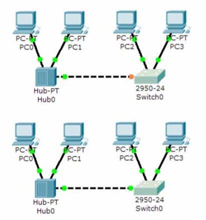
10 Perform the following steps to connect PC2 to Switch0: 1. Click once on PC2 2. Choose FastEthernet 3. Drag the cursor to Switch0 4. Click once on Switch0 and choose FastEthernet0/1 5. Notice the green link lights on PC2 Ethernet NIC and amber light Switch0 FastEthernet0/1 port The switch port is temporarily not forwarding frames, while it goes through the stages for the Spanning Tree Protocol (STP) process. 6. After a about 30 seconds the amber light will change to green indicating that the port has entered the forwarding stage. Frames can now forwarded out the switch port. Page 10 of 43

11 Step 5: Configuring IP Addresses and Subnet Masks on the Hosts Page 11 of 43
12 Also, notice this is where you can change the Bandwidth (speed) and Duplex of the Ethernet NIC (Network Interface Card). The default is Auto (auto negotiation), which means the NIC will negotiate with the hub or switch. The bandwidth and/or duplex can be manually set by removing the check from the Auto box and choosing the specific option. Bandwidth Auto If the host is connected to a hub or switch port which can do 100 Mbps, then the Ethernet NIC on the host will choose 100 Mbps (Fast Ethernet). Otherwise, if the hub or switch port can only do 10 Mbps, then the Ethernet NIC on the host will choose 10 Mbps (Ethernet) Page 12 of 43
, then the Ethernet NIC on the host will")
 The information is automatically saved when entered. Repeat these steps for the other hosts.")
13 Duplex - Auto Hub: INSTITUTE OF SOUTHERN PUNJAB (ISP), If the host is connected to a hub, then the Ethernet NIC on the host will choose Half Duplex. Switch: If the host is connected to a switch, and the switch port is configured as Full Duplex (or Auto negotiation), then the Ethernet NIC on the host will choose Full Duplex. If the switch port is configured as Half Duplex, then the Ethernet NIC on the host will choose Half Duplex. (Full Duplex is a much more efficient option.) The information is automatically saved when entered. Repeat these steps for the other hosts. Use the information below for IP Addresses and Subnet Masks. Page 13 of 43
 over each host.")


14 Verify the Information: INSTITUTE OF SOUTHERN PUNJAB (ISP), To verify the information that you entered, move the Select tool (arrow) over each host. Deleting a Device or Link: To delete a device or link, choose the Delete tool and click on the item you wish to delete. Step 6: Connecting Hub0 to Switch0 To connect like-devices, like a Hub and a Switch, we will use a Cross-over cable. Click once the Cross-over Cable from the Connections options. Page 14 of 43

15 Page 15 of 43

16 Page 16 of 43
17 Lab Task: 1. Design the following Topologies for LAN using hub and switches and 15 PC s connected together a) Buss b) Star c) Tree d) Hybrid Topologies Home Task: 1. Briefly describe the Connections section of Packet Tracer. END OF LAB 1 Page 17 of 43
18 2. Network Simulation: Lab 2- Network Simulation In this part, we are going to use the simulator to simulate traffic between hosts. For this scenario, delete the switch and host PC3, then connect host PC2 to the hub from lab 1. Observe the flow of data from PC0 to PC1 by Creating Network Traffic. a) Switch to Simulation Mode by selecting the tab that is partially hidden behind the Real Time tab in the bottom right-hand corner. The tab has the icon of a stopwatch on it. NOTE: When Simulation Mode is chosen, a Simulation Panel will appear on the right side of the screen. This panel can be moved by moving the cursor at the top of the panel until it changes and then double-clicking on it. The panel can be restored to the original location by double-clicking on the Title bar. If the panel is closed, click on the Event List button. Page 18 of 43
 Select a Simple PDU by clicking the closed envelope in the Common Tools Bar on the right. Move to PC0 and click to establish the source.")

19 b) Click on Edit Filters, and then select All/None to deselect every filter. Then choose ARP and ICMP and click in the workspace to close the Edit Filters window. c) Select a Simple PDU by clicking the closed envelope in the Common Tools Bar on the right. Move to PC0 and click to establish the source. Move to PC1 and click to establish the destination. Notice that two envelopes are now positioned beside PC0. This is referred to as a data traffic scenario. One envelope is an ICMP packet, while the other is an ARP packet. The Event List in the Simulation Panel will identify exactly which envelope represents ICMP and which represents an ARP. Page 19 of 43
 Select Auto Capture / Play from the Simulation Panel Play Controls.")
 Choose the Reset Simulation button in the Simulation window.")
20 A scenario may be deleted by clicking on the Delete button in the Scenario panel. Multiple scenarios can be created by clicking on the new button in the Scenario panel. The scenarios can then be toggled between without deleting. d) Select Auto Capture / Play from the Simulation Panel Play Controls. Below the Auto Capture / Play button is a horizontal bar, with a vertical button that controls the speed of the simulation. Dragging the button to the right will speed up the simulation, while dragging is to the left will slow down the simulation. e) Choose the Reset Simulation button in the Simulation window. Notice that the ARP envelope is no longer present. This has reset the simulation but has not cleared any configuration changes or MAC / ARP table entries. Page 20 of 43
 Choose the Power Cycle Devices button on the bottom left, above the device icons. Choose: Yes Notice that both the ICMP and ARP envelopes are now present.")
21 f) Choose the Capture / Forward button. Notice that the ICMP envelope moved forward one device and stopped. The Capture / Forward button will allow you to move the simulation one step at a time. h) Choose the Power Cycle Devices button on the bottom left, above the device icons. Choose: Yes Notice that both the ICMP and ARP envelopes are now present. The Power Cycle Devices will clear any configuration changes not saved and clear the MAC / ARP tables. Page 21 of 43
 Select the Command Prompt and type the command: arp a d) Notice that the MAC address for PC2 is in the ARP table (to view the MAC address of PC2, click on PC2 and select the Config")
22 2.1- Address Resolution Protocol (ARP) a) Choose the Auto Capture / Play button and allow the simulation to run completely. b) Click on PC-0 and select the Desktop tab. c) Select the Command Prompt and type the command: arp a d) Notice that the MAC address for PC2 is in the ARP table (to view the MAC address of PC2, click on PC2 and select the Config tab). Page 22 of 43
 Click on PC2 to view the ARP table. Then close the ARP Table window.")
23 e) To examine the ARP tables for PC1 and PC2 in another way, click on the Inspect Tool. Then click on PC1 and the ARP table will appear in a new window. Note that PC2 does not have an entry in the ARP table yet. Close the ARP Table window. f) Click on PC2 to view the ARP table. Then close the ARP Table window. NOTE: To deactivate the Inspect Tool, click on the Select Tool Page 23 of 43
 Select")
 Move the cursor to the Logical Workspace and click")
24 2.2 Adding Routers and Installing Modules a) In the Network Component Box, click on the Router b) Select an 1841 Router. c) Move the cursor to the Logical Workspace and click on the desired location. Page 24 of 43
 Click on the router to bring up the Configuration Window.")
25 NOTE: If multiple instances of the same device are needed press and hold the Ctrl button, click on the desired device, and then release the Ctrl button. A copy of the device will be created and can now be move to the desired location. d) Click on the router to bring up the Configuration Window. This window has three modes: Physical, Config, and CLI (Physical is the default mode). The Physical mode is used to add modules to a device, such as a WAN Interface Card (WIC). The Config mode is used for basic configuration. Commands are entered in a simple GUI format, with actual equivalent IOS commands shown in the lower part of the window. The CLI mode allows for advanced configuration of the device. This mode requires the user to enter the actual IOS commands just as they would on a live device. Page 25 of 43
 Select the WIC-2T module and drag it to Slot 0 on the router. Then drag a WIC Cover to Slot 1.")
26 e) In the Physical mode, click on the router power switch to turn the device off. f) Select the WIC-2T module and drag it to Slot 0 on the router. Then drag a WIC Cover to Slot 1. g) Power the device back on. Page 26 of 43
27 h) Click on the Network Component Box and select Connections. Then select a Copper Straight-through connection to connect the router to the hub. NOTE: The Smart Connection can be used to automatically select the appropriate cable type. However, the user will have no choice as to which interface the connection is assigned to; it will take the first available appropriate interface. Click on the hub and choose Port 3. Then click on the router and choose interface FastEthernet 0/0. Page 27 of 43
28 2.3 Basic Router Configurations using Config Mode a) Click on the Config mode tab of Router0 to begin configuring the device b) After the device has finished booting, change the display name of the router to CISCO_1. Changing the display name does not affect the configuration. NOTE: If the device hangs up in the booting process, save the activity. Then close the application and reopen the file c) Click in the Hostname field and type CISCO_1, then press the TAB key. Note the equivalent IOS command is entered in the lower portion of the window. d) Click on interface FastEthernet 0/0 and assign the IP address , then press the TAB key. Enter the subnet mask Page 28 of 43
.")
29 e) Click the Port Status to On to enable the port (no shutdown). Page 29 of 43
30 2.4 - Creating a Copy of Existing Router a) Make sure that the existing router is selected (it will be grayed out). b) In the Main Tool Bar click on the Copy tool. c) Click on the Paste tool and the copied device will appear in the work area. d) Drag the new device to the desired location. e) Click on the Network Component Box and select Connections. Then select the Serial DCE connection. f) Click on the CISCO_1 router and connect to the Serial 0/0/0 interface. Page 30 of 43
31 g) Click on the new router (copy CISCO_1) and connect to the Serial 0/0/0 interface. Page 31 of 43
32 2.5 - Configuring the Wide Area Network (WAN) Link a) Click on the CISCO_1 router and select the Config mode b) Select interface Serial 0/0/0 c) Configure the interface Serial 0/0/0 with the IP address , then press the TAB key and enter the subnet mask on the interface. d) Set the clock rate to e) Click the Port Status to On to enable the port (no shutdown). f) Click on the new router and select the Config mode. g) Change the Display Name and Hostname to CISCO_2. h) Configure the interface Serial 0/0/0 with the IP address , then press the TAB key and enter the subnet mask on the interface. i) Click the Port Status to On to enable the port (no shutdown). NOTE: The link lights on the serial link should change from red to green to indicate the link is active. Page 32 of 43
33 2.6 - Configuring the Routing Protocol: Routing Information Protocol (RIP) a) Click on the CISCO_1 router and select the Config tab. Then click on RIP and add the network address and b) Click on the CISCO_2 router and select the Config tab. Then click on RIP and add the network address c) Go to each PC and set the Default Gateway to Page 33 of 43
34 2.7 - Setting the default Gateway on the Personal Computers (PCs) a) Click on PC0 and select the Config tab. Enter the default gateway address b) Click on PC1 and select the Config tab. Enter the default gateway address c) Click on PC2 and select the Config tab. Enter the default gateway address Page 34 of 43
35 2.8 Testing the Connectivity of the Build Network a) Click on the Simulation mode. b) Select a Simple PDU and click on PC-A as the source, then click on Cisco_2 as the destination. The ping should be successful. 2.9 Saving the Packet Tracer File a) Save the Packet Tracer file with the name: Your Name-Class-Semester-Section-lab2 END OF LAB 2 Page 35 of 43
36 Lab 3- Configuring DHCP & DNS & Web Server 1. Start Packet Tracer using Realtime mode. Options -> Preferences o Enable Show Link Lights o Disable Hide Device Label 2. Configuring the DHCP Server Add a server. Global Settings: Change the Display Name to DHCP Server Set the Gateway to FastEthernet: Set the IP address to Set the Subnet Mask to HTTP: Set HTTP Service and HTTPS Service to Off DHCP: Set the Default Gateway to Set the DNS Server to Set the Start IP Address to DNS: Set the Service to Off Page 36 of 43
37 2. Configuring the DNS Server Add a server. Global Settings: Change the Display Name to DNS Server Set the Gateway to FastEthernet: Set the IP address to Set the Subnet Mask to HTTP: Set HTTP Service and HTTPS Service to Off DHCP: Set the Service to Off DNS: Entering the Domain Name o Enter for the Domain Name o Enter for IP Address o Click Add Entering the Domain Name o Enter for the Domain Name o Enter for IP Address o Click Add Page 37 of 43
38 3. Configuring the Web Server Add a server. Global Settings: Change the Display Name to Web Server: Set the Gateway to FastEthernet: Set the IP address to Set the Subnet Mask to DHCP: Set the Service to Off DNS: Set the Service to Off HTTP Change the sentence, <hr>welcome to Packet Tracer 5.0, the best thing since... Packet Tracer 4.0. to <hr> Welcome to Tsrb's public web page! You may add other information as well. Page 38 of 43
39 4. Configuring the Web Server Add a server. Global Settings: Change the Display Name to Web Server: Set the Gateway to FastEthernet: Set the IP address to Set the Subnet Mask to DHCP: Set the Service to Off DNS: Set the Service to Off Page 39 of 43
40 HTTP INSTITUTE OF SOUTHERN PUNJAB (ISP), Change the sentence, <hr>welcome to Packet Tracer 5.0, the best thing since... Packet Tracer 4.0. to <hr> This is the corporate internal network! You may add other information as well. 5. Configure Two Client Computers using DHCP Add two client computers. Global Settings: Change the Display Names to Dynamic 1 and to Dynamic 2 respectively Set the Gateway/DNS to DHCP FastEthernet: Set the IP Configuration to DHCP 6. Configure One Client Computers using Static IP Addressing Add two client computers. Global Settings: Change the Display Name to Static Set the Gateway/DNS to Static Set Gateway to Set the DNS Server to FastEthernet: Be sure the configuration is set to Static Set the IP address to Set the Subnet Mask to Page 40 of 43
41 7. Adding switches INSTITUTE OF SOUTHERN PUNJAB (ISP), Add two switches. Connect the servers to one switch using a straight-through cable. Connect the client computers to the other switch using a straight-through cable. Interconnect the two switches using a crossover cable. 8. Verify connectivity Ping (ICMP) o From a client computer use the Desktop Command prompt to ping the other client computers and the servers. o Example: From the Dynamic 1 client, C> ping o The first one or two pings may fail, but you should receive a reply on the later pings. This is due to the ping timing out while the ARP process takes place (later). Web Browser (HTTP) o On the client computers use the Desktop Web Browser, enter the URLs of the Web Servers and o You should see the web pages that you created on these servers. Page 41 of 43
42 9. Using Simulation Mode INSTITUTE OF SOUTHERN PUNJAB (ISP), Click on Simulation. Note: To reset a simulation, click on Reset Simulation Click on Edit Filters Choose Show All/None so that all the boxes (protocols) are unchecked. Select (check) the following protocols: DHCP, ICMP, HTTP, DNS. Web Browser (HTTP) On the client computers use the Desktop Web Browser, enter the URLs of the Web Servers or Click on Auto Capture/Play (automatically forwards the packets) or Capture Forward (must keep clicking to advance the packets) DHCP Reset the simulation by clicking on Reset Simulation To view DHCP, on one of the Dynamic client computers using DHCP go to the Desktop Command prompt. To have the client computer ask for new IP address and other information from the DHCP server, enter the command: C> ipconfig /renew Page 42 of 43
43 END OF LAB 3 Page 43 of 43
Experiment 3: Protocol Visualization with Packet Tracer
 Experiment 3: Protocol Visualization with Packet Tracer Learning Objectives: Explore Packet Tracer Real-time mode Explore the Logical Workspace Explore Packet Tracer operation Connect devices Examine a
Lab#01 - Introduction to Packet Tracer
 Lab#01 - Introduction to Packet Tracer What is Packet Tracer? Packet Tracer is a protocol simulator developed by Dennis Frezzo and his team at Cisco Systems. Packet Tracer (PT) is a powerful and dynamic
Introduction to the Packet Tracer Interface using a Hub Topology
 Introduction to Packet Tracer What is Packet Tracer? Packet Tracer is a protocol simulator developed by Dennis Frezzo and his team at Cisco Systems. Packet Tracer (PT) is a powerful and dynamic tool that
GAME100 Lab 5. Before beginning the lab, please download and install Cisco Packet Trace
 GAME100 Lab 5 Name: Part 1: Learn to Use Packet Tracer Objectives Develop an understanding of the basic functions of Packet Tracer. Create/model a simple Ethernet network using two hosts and a switch.
Internetworking with Packet Tracer
 Internetworking with Packet Tracer Objectives Develop an understanding of the basic functions of Packet Tracer. Create/model two simple Ethernet networks connected by a switch. Observe traffic behavior
Packet Tracer: Novice Session. Packet Tracer: Novice Session 2007 Cisco Systems, Inc. All rights reserved. Cisco Public
 Packet Tracer: Novice Session Packet Tracer: Novice Session 1 How Can I Use Packet Tracer? Problem Scenario: Your students need to learn how to configure a router Ethernet interface and to verify connectivity
Packet Tracer: Novice Session 2007 Cisco Systems, Inc. All rights reserved. Cisco Public. Packet Tracer: Novice Session
 Packet Tracer: Novice Session Packet Tracer: Novice Session 1 How Can I Use Packet Tracer? Problem Scenario: Your students need to learn how to configure a router Ethernet interface and to verify connectivity
Use of the TCP/IP Protocols and the OSI Model in Packet Tracer
 Communication Networks [Netw501] Spring 2018 Tutorial 3 Packet Tracer Activity 3 Use of the TCP/IP Protocols and the OSI Model in Packet Tracer Introduction: In Packet Tracer simulation mode, detailed
CNPE Communications and Networks Lab Book: Data Transmission Over Digital Networks
 Lab Book: Data Transmission Over Digital Networks Contents Data Transmission Over Digital Networks... 3 Lab Objectives... 3 Lab Resources... 3 Task 1 Build the Home Network... 3 Task 2 Configure IP Addresses...
Packet Tracer - Explore a Network
 Topology Objectives Part 1: Examine Internetwork Traffic at Branch Part 2: Examine Internetwork Traffic to Central Part 3: Examine Internet Traffic from Branch Background This simulation activity is intended
Packet Tracer Create a Simple Network Using Packet Tracer
 Using Packet Tracer Topology Addressing Table Device Interface IP Address Subnet Mask Default Gateway PC Ethernet0 DHCP 192.168.0.1 Wireless Router Cisco.com Server LAN 192.168.0.1 255.255.255.0 Internet
NET323 D: NETWORKS PROTOCOLS
 1 NET323 D: NETWORKS PROTOCOLS Networks and Communication Systems Department TA. Anfal AlHazzaa Lab # 2 : Hub Vs. Switch Lab Objectives 2 To create two small LANs contain three PCs using Packet Tracer
NETWORK LAB 2 Configuring Switch Desktop
 Configuring Switch 1. Select the switch tab and then add a switch from the list of switches we have to the workspace, we will choose (2950-24) switch. 2. Add a number of PCs next to the switch in order
NET323 D: NETWORKS PROTOCOLS
 1 NET323 D: NETWORKS PROTOCOLS Networks and Communication Systems Department Lab # 1 : Introduction to Packet Tracer Lab Objectives 2 To become familiar with Packet Tracer Interface To differentiate between
Packet Tracer - Investigating the TCP/IP and OSI Models in Action (Instructor Version Optional Packet Tracer)
") (Instructor Version Optional Packet Tracer) Instructor Note: Red font color or gray highlights indicate text that appears in the instructor copy only. Optional activities are designed to enhance understanding
(Instructor Version Optional Packet Tracer) Instructor Note: Red font color or gray highlights indicate text that appears in the instructor copy only. Optional activities are designed to enhance understanding
NET323 D: NETWORKS PROTOCOLS
 1 NET323 D: NETWORKS PROTOCOLS Networks and Communication Systems Department TA. Anfal AlHazzaa Lab # 8: DNS (Domain Name System) Lab Objectives 2 To understand how DNS works Lab Content 3 Introduction
Packet Tracer Mini-Lab 04: Supplement Configuring 2 LANs and 2 Routers with Config in Packet Tracer
 Packet Tracer Mini-Lab 04: Supplement Configuring 2 LANs and 2 Routers with Config in Packet Tracer CAVEAT: THE LABS IN CC2-180 MAY NOT WORK ENTIRELY AS PLANNED. WE WILL BE UTILIZING BOTH A SERVER 2012
CNBK Communications and Networks Lab Book: Purpose of Hardware and Protocols Associated with Networking Computer Systems
 Lab Book: Purpose of Hardware and Protocols Associated with Networking Computer Systems Contents Purpose of Hardware and Protocols Associated with Computer Networks... 3 Lab Objectives... 3 Lab Resources...
Lab - Connect to a Router for the First Time
 Introduction In this lab, you will configure basic settings on a wireless router. Recommended Equipment A computer with Windows installed An Ethernet NIC installed Wireless router Ethernet patch cable
PreLab for CS356 Lab NIL (Lam) (To be submitted when you come for the lab)
 (To be submitted when you come for the lab)") PreLab for CS356 Lab NIL (Lam) (To be submitted when you come for the lab) Name: UT EID: 1. Differentiate between Routers, Switches, and Hubs. 2. Explain subnet masks. 3. For this lab, where is subnet
PreLab for CS356 Lab NIL (Lam) (To be submitted when you come for the lab) Name: UT EID: 1. Differentiate between Routers, Switches, and Hubs. 2. Explain subnet masks. 3. For this lab, where is subnet
Lab Correcting RIPv2 Routing Problems
 Lab 9.4.2 Correcting RIPv2 Routing Problems e Interface IP Address Subnet Mask Default Gateway Device Host Name Interface IP Address Subnet Mask Default Gateway R1 BRANCH1 Fast Ethernet 0/0 172.16.0.1
CS356 Lab NIL (Lam) In this lab you will learn: Cisco 2600 Router Configuration Static Routing PartB 20 min Access Control Lists PartC 30 min Explore!
 In this lab you will learn: Cisco 2600 Router Configuration Static Routing PartB 20 min Access Control Lists PartC 30 min Explore!") CS356 Lab NIL (Lam) In this lab you will learn: PartA Time: 2 hrs 40 min Cisco 2600 Router Configuration Static Routing PartB 20 min Access Control Lists PartC 30 min Explore! Components used: 2 computers
CS356 Lab NIL (Lam) In this lab you will learn: PartA Time: 2 hrs 40 min Cisco 2600 Router Configuration Static Routing PartB 20 min Access Control Lists PartC 30 min Explore! Components used: 2 computers
Device Interface IP Address Subnet Mask Default Gateway
 Topology Diagram Addressing Table Device Interface IP Address Subnet Mask Default Gateway BRANCH HQ ISP Fa0/0 172.20.1.129 255.255.255.128 N/A S0/0/0 172.20.1.1 255.255.255.128 N/A Fa0/0 172.20.0.129 255.255.255.128
Configuration and management of Networks LAB 1 Introduction to packet tracer
 LAB 1 Introduction to packet tracer Objectives: Learn Packet Tracer to design and simulate networks. Learn to create a simple LAN with two PCs using an Ethernet hub and two straight through cables to connect
Activity Configuring Routers, Web, DHCP, DNS and FTP Servers
 Activity Configuring Routers, Web, DHCP, DNS and FTP Servers Objectives: 1. Configure a network using 2 routers, 4 switches, 6 servers and 8 PC s. 2. Assign network addresses. 3. Configure a DHCP server
CS 326e Lab 2, Edmondson-Yurkanan, Spring 2004 Router Configuration, Routing and Access Lists
 CS 326e Lab 2, Edmondson-Yurkanan, Spring 2004 Router Configuration, Routing and Access Lists Name: In this lab you will learn: PartA Cisco 2600 Router Configuration Static Routing PartB 20 min Dynamic
Chapter 10 - Configure ASA Basic Settings and Firewall using ASDM
 Chapter 10 - Configure ASA Basic Settings and Firewall using ASDM This lab has been updated for use on NETLAB+ Topology Note: ISR G1 devices use FastEthernet interfaces instead of GigabitEthernet interfaces.
Classful Address Subnet Mask Number of Hosts per Subnet (2 x 2)
") LAB 1 Exercise 1- Subnetting exercises. Write the subnet, broadcast address, and valid host range for question 1 through question 6: 1. 192.168.100.25/30 2. 192.168.100.37/28 3. 192.168.100.66/27 4. 192.168.100.17/29
LAB 1 Exercise 1- Subnetting exercises. Write the subnet, broadcast address, and valid host range for question 1 through question 6: 1. 192.168.100.25/30 2. 192.168.100.37/28 3. 192.168.100.66/27 4. 192.168.100.17/29
Lab 7.5.1: Basic Wireless Configuration
 Topology Diagram Learning Objectives Configure options in the Linksys Setup tab. Configure options in the Linksys Wireless tab. Configure options in the Linksys Administration tab. Configure options in
Lab Viewing Wireless and Wired NIC Information
 Objectives Part 1: Identify and Work with PC NICs Part 2: Identify and Use the System Tray Network Icons Background / Scenario This lab requires you to determine the availability and status of the network
PT Activity 5.6.1: Packet Tracer Skills Integration Challenge Topology Diagram
 Topology Diagram All contents are Copyright 2008 Cisco Systems, Inc. All rights reserved. This document is Cisco Public Information. Page 1 of 6 Addressing Table Device Interface IP Address Subnet Mask
Packet Tracer Simulation - TCP and UDP Communications
 Topology Objectives Part 1: Generate Network Traffic in Simulation Mode Part 2: Examine the Functionality of the TCP and UDP Protocols Background This simulation activity is intended to provide a foundation
1. Which OSI layers offers reliable, connection-oriented data communication services?
 CCNA 1 Practice Final Exam Answers v4.0 100% 1. Which OSI layers offers reliable, connection-oriented data communication services? application presentation session transport network 2. Refer to the exhibit.
CS 356 Lab #1: Basic LAN Setup & Packet capture/analysis using Ethereal
 CS 356 Lab #1: Basic LAN Setup & Packet capture/analysis using Ethereal Tasks: Time: 2:00 hrs (Task 1-6 should take 45 min; the rest of the time is for Ethereal) 1 - Verify that TCP/IP is installed on
Lab - Configure a NIC to Use DHCP in Windows
 Introduction In this lab, you will configure an Ethernet NIC to use DHCP to obtain an IP address and test connectivity between two computers. Recommended Equipment Wireless router Two computers running
Packet Tracer Mini-Lab 05: Supplement Configuring 2 LANs with 2 Routers using CLI in Packet Tracer
 Packet Tracer Mini-Lab 05: Supplement Configuring 2 LANs with 2 Routers using CLI in Packet Tracer CAVEAT: THE LABS IN CC2-180 MAY NOT WORK ENTIRELY AS PLANNED. WE WILL BE UTILIZING BOTH A SERVER 2012
NET323 D: NETWORKS PROTOCOLS
 1 NET323 D: NETWORKS PROTOCOLS Networks and Communication Systems Department TA. Anfal AlHazzaa Lab # 6 : Dynamic Route (OSPF Single area) Lab Objectives 2 To connect small LANs using routers. To configure
Interconnecting Cisco Networking Devices Part1 ( ICND1) Exam.
 Exam.") Cisco 640-822 Interconnecting Cisco Networking Devices Part1 ( ICND1) Exam TYPE: DEMO http://www.examskey.com/640-822.html Examskey Cisco 640-822 exam demo product is here for you to test quality of the
Cisco 640-822 Interconnecting Cisco Networking Devices Part1 ( ICND1) Exam TYPE: DEMO http://www.examskey.com/640-822.html Examskey Cisco 640-822 exam demo product is here for you to test quality of the
This document is exclusive property of Cisco Systems, Inc. Permission is granted to print and copy this document for non-commercial distribution and
 This document is exclusive property of Cisco Systems, Inc. Permission is granted to print and copy this document for non-commercial distribution and exclusive use by instructors in the CCNA Exploration:
Objective: Select the appropriate media, cables, ports, and connectors to connect switches to other network devices and hosts
 Curriculum Name CCENT Study Guide 2 Section 9.2 Troubleshooting Layer 1 and Layer 2 Issues As you work through this troubleshooting section, you can review the material necessary to prepare you to obtain
Packet Tracer Mini-Lab 08: Supplement Configuring 2 LANs/2 Routers using Config, CLI, & RIPv2
 Packet Tracer Mini-Lab 08: Supplement Configuring 2 LANs/2 Routers using Config, CLI, & RIPv2 CAVEAT: THE LABS IN CC2-180 MAY NOT WORK ENTIRELY AS PLANNED. WE WILL BE UTILIZING BOTH A SERVER 2012 R2 HOST
NET323 D: NETWORKS PROTOCOLS
 1 NET323 D: NETWORKS PROTOCOLS Networks and Communication Systems Department TA. Anfal AlHazzaa Lab # 5 : Dynamic Route (RIP) Lab Objectives 2 To connect small LANs using routers. To configure dynamic
Packet Tracer - Connect a Router to a LAN (Instructor Version)
") (Instructor Version) Instructor Note: Red font color or gray highlights indicate text that appears in the instructor copy only. Topology Addressing Table Device Interface IP Address Subnet Mask Default
(Instructor Version) Instructor Note: Red font color or gray highlights indicate text that appears in the instructor copy only. Topology Addressing Table Device Interface IP Address Subnet Mask Default
Network II Lab 01. Part 01: Interface Overview. Program interface
 Part 01: Interface Overview Network II Lab 01 This initial interface contains ten components. If you are unsure of what a particular interface item does, move your mouse over the item and a help balloon
Activity Configuring and Securing a Wireless LAN in Packet Tracer
 Activity Configuring and Securing a Wireless LAN in Packet Tracer Objectives: 1. Configure a Wireless Access Point (WAP) local IP address. 2. Configure a WAP with an SSID. 3. Change the administrator s
Lab 1. CLI Navigation. Scenario. Initial Configuration for R1
 Lab 1 CLI Navigation This lab covers the most basic skills for accessing and using the command-line interface (CLI) on a Cisco router or switch. Many of the small, picky details of how the CLI works cannot
Introduction to Routing and Packet Forwarding
 Introduction to Routing and Packet Forwarding Routing Protocols and Concepts 1 Objectives Identify a router as a computer with an OS and hardware designed for the routing process. Demonstrate the ability
Packet Tracer - Using Traceroute to Discover the Network (Instructor Version)
") (Instructor Version) Instructor Note: Red font color or Gray highlights indicate text that appears in the instructor copy only. Topology Scenario The company you work for has acquired a new branch location.
(Instructor Version) Instructor Note: Red font color or Gray highlights indicate text that appears in the instructor copy only. Topology Scenario The company you work for has acquired a new branch location.
LevelOne FBR User s Manual. 1W, 4L 10/100 Mbps ADSL Router. Ver
 LevelOne FBR-1416 1W, 4L 10/100 Mbps ADSL Router User s Manual Ver 1.00-0510 Table of Contents CHAPTER 1 INTRODUCTION... 1 FBR-1416 Features... 1 Package Contents... 3 Physical Details... 3 CHAPTER 2
EXAM - HP0-Y52. Applying HP FlexNetwork Fundamentals. Buy Full Product.
 HP EXAM - HP0-Y52 Applying HP FlexNetwork Fundamentals Buy Full Product http://www.examskey.com/hp0-y52.html Examskey HP HP0-Y52 exam demo product is here for you to test the quality of the product. This
Lab : Challenge OSPF Configuration Lab. Topology Diagram. Addressing Table. Default Gateway. Device Interface IP Address Subnet Mask
 Topology Diagram Addressing Table Device Interface IP Address Subnet Mask Default Gateway Fa0/0 HQ S0/0/0 S0/0/1 Lo1 10.10.10.1 255.255.255.252 Fa0/0 Branch1 S0/0/0 S0/0/1 Fa0/0 Branch2 S0/0/0 S0/0/1 PC1
CCNA 1 Final Exam Answers UPDATE 2012 eg.1
 CCNA 1 Final Exam Answers UPDATE 2012 eg.1 January 12th, 2012AdminLeave a commentgo to comments Which of the following are the address ranges of the private IP addresses? (Choose three.) 10.0.0.0 to 10.255.255.255
Lab 9.6.3: EIGRP Troubleshooting Lab
 Topology Diagram Addressing Table Device Interface IP Address Subnet Mask Default Gateway Fa0/0 172.18.64.1 255.255.192.0 N/A HQ S0/0/0 209.165.202.129 255.255.255.252 N/A S0/0/1 209.165.202.133 255.255.255.252
Broadband Router DC-202. User's Guide
 Broadband Router DC-202 User's Guide Table of Contents CHAPTER 1 INTRODUCTION... 1 Broadband Router Features... 1 Package Contents... 3 Physical Details...3 CHAPTER 2 INSTALLATION... 5 Requirements...
Networking Notes. Common Internet Speeds. Online Speed Test myspeed.visualware.com
 Networking Notes Common Internet Speeds Dial Up 56 kbs 1000kbs = 1 mbs (1 user capacity) DSL 1.5 mbs (1 channel 10 user capacity) T1 1.5 mbs (24 channel 500 user capacity) Scalable Ethernet (Adjustable
Lab Using Wireshark to Examine Ethernet Frames
 Topology Objectives Part 1: Examine the Header Fields in an Ethernet II Frame Part 2: Use Wireshark to Capture and Analyze Ethernet Frames Background / Scenario When upper layer protocols communicate with
Lecture (02) Switch remote configuration peer2peer star network clients/server star network Traffic analysis using Packet Tracer
 Switch remote configuration peer2peer star network clients/server star network Traffic analysis using Packet Tracer") Lecture (02) Switch remote configuration peer2peer star network clients/server star network Traffic analysis using Packet Tracer Dr. Ahmed M. ElShafee ١ Topology ٢ Preparation ٣ Commands summery ٤ enabl
Lecture (02) Switch remote configuration peer2peer star network clients/server star network Traffic analysis using Packet Tracer Dr. Ahmed M. ElShafee ١ Topology ٢ Preparation ٣ Commands summery ٤ enabl
6.5.1: Packet Tracer Skills Integration Challenge Activity Topology Diagram
 6.5.1: Packet Tracer Skills Integration Challenge Activity Topology Diagram All contents are Copyright 1992 2007 Cisco Systems, Inc. All rights reserved. This document is Cisco Public Information. Page
on the bottom left hand corner you will find all the devices you need.
 Create a simple LAN in packet tracer Things you will need 1) Generic PC 1) Switch 1) Server open packet tracer on the bottom left hand corner you will find all the devices you need. Click on END DEVICES
Lab - Configure Wireless Router in Windows
 Introduction In this lab, you will configure and test the wireless settings on a wireless router. Recommended Equipment A computer with Windows installed A Wireless NIC installed An Ethernet NIC installed
Lab Applying a Logical Layered Model to a Physical Network
 Lab 3.1.1 Applying a Logical Layered Model to a Physical Network Objective In this exercise, you will use various Cisco IOS commands and a protocol analyzer to map the layers in the OSI model to the encapsulated
Antonio Cianfrani. Packet Tracer
 Antonio Cianfrani Packet Tracer Packet Tracer (1/2) Packet Tracer? Cisco Packet Tracer is a software able to emulate CISCO networking devices. Packet Tracer features: Allows to create network topologies
Lab Using Wireshark to Examine Ethernet Frames
 Topology Objectives Part 1: Examine the Header Fields in an Ethernet II Frame Part 2: Use Wireshark to Capture and Analyze Ethernet Frames Background / Scenario When upper layer protocols communicate with
UIP1869V User Interface Guide
 UIP1869V User Interface Guide (Firmware version 0.1.8 and later) Table of Contents Opening the UIP1869V's Configuration Utility... 3 Connecting to Your Broadband Modem... 5 Setting up with DHCP... 5 Updating
Lab 5.6.2: Challenge RIP Configuration
 Topology Diagram Addressing Table Device Interface IP Address Subnet Mask Default Gateway BRANCH HQ ISP PC1 PC2 PC3 Fa0/0 S0/0/0 Fa0/0 S0/0/0 S0/0/1 Fa0/0 S0/0/1 NIC NIC NIC Learning Objectives Upon completion
OSI Model with Protocols. Layer Name PDU Address Protocols Device
 NetEss Name: Networking Essentials Prof. CHIN OSI Model with Protocols Layer Name PDU Address Protocols Device 7 Application Data FTP, SSH, Telnet, SMTP, DNS TFTP,HTTP, POP3, IMAP, HTTPS 6 Presentation
Lab IP Addresses and Network Communication
 Lab 3.5.2 IP Addresses and Network Communication Objectives Build a simple peer-to-peer network and verify physical connectivity. Assign various IP addresses to hosts and observe the effects on network
Smart Serial. Show interfaces. Shut down. logging synchronous
 SEMESTER 2 Chapter 2 Static Networking V 4.0 2.1.1 What are the primary responsibilities of the router? 2.1.3 What is the first serial connector described called at the router end? What is the first serial
The following steps should be used when configuring a VLAN on the EdgeXOS platform:
 EdgeXOS VLANs VLAN Overview This document provides an overview of what a VLAN is and how it is configured on the EdgeXOS platform. Use the step-by-step guide below to configure a VLAN on the Edge appliance
Static Routing. Routing Protocols and Concepts Chapter 2. ITE PC v4.0 Chapter Cisco Systems, Inc. All rights reserved.
 Static Routing Routing Protocols and Concepts Chapter 2 1 Objectives Define the general role a router plays in networks. Describe the directly connected networks, different router interfaces Examine directly
Lab 7.5.3: Troubleshooting the Wireless WRT300N
 Lab 7.5.3: Troubleshooting the Wireless WRT300N Topology Diagram Addressing Table Device Interface IP Address Subnet Mask Default Gateway Fa0/1.5 5.5.5.10 255.255.255.0 N/A Fa0/1.10 192.168.10.1 255.255.255.0
Lab DHCP Client Setup
 Lab 9.3.5 DHCP Client Setup Objective The purpose of this lab is to introduce Dynamic Host Configuration Protocol (DHCP) and the process for setting up a network computer as a DHCP client to use DHCP services.
Quick Installation Guide of Acer WLAN 11b Broadband Router
 Preparation 1 At lease one PC with IEEE802.11b WLAN client installed. 2 One straight-through Category 5 Ethernet cable, used to link WAN interface to xdsl or CM for Internet connection. 3 Acer WLAN 11b
CCNA 1 v5.0 R&S ITN Final Exam 2014
 CCNA 1 v5.0 R&S ITN Final Exam 2014 1 Refer to the exhibit. The network administrator enters these commands into the R1 router: R1# copy running-config tftp Address or name of remote host [ ]? When the
Lab 1.3.2: Review of Concepts from Exploration 1 - Challenge
 Lab 1.3.2: Review of Concepts from Exploration 1 - Challenge Topology Diagram Learning Objectives Upon completion of this lab, you will be able to: Create a logical topology given network requirements
Lab : OSPF Troubleshooting Lab
 Topology Diagram Addressing Table Device Interface IP Address Subnet Mask Default Gateway Fa0/0 10.10.0.1 255.255.252.0 N/A HQ S0/0/0 172.16.7.1 255.255.255.252 N/A S0/0/1 172.16.7.5 255.255.255.252 N/A
CHAPTER 7 ADVANCED ADMINISTRATION PC
 ii Table of Contents CHAPTER 1 INTRODUCTION... 1 Broadband ADSL Router Features... 1 Package Contents... 3 Physical Details... 4 CHAPTER 2 INSTALLATION... 6 Requirements... 6 Procedure... 6 CHAPTER 3 SETUP...
Hochschule Bremen Networking Lab
 Hochschule Bremen Networking Lab User Manual Welcome to the Hochschule Bremen networking lab. This manual will give you a brief introduction on how to use the PCs and networking hardware in the lab. The
Troubleshooting Network analysis Software communication tests and development Education. Protocols used for communication (10 seconds capture)
") Lab 1 Wireshark Wireshark is an open source and free packet analyser used for many purposes, such as: Troubleshooting Network analysis Software communication tests and development Education This reports
Lab 1 Wireshark Wireshark is an open source and free packet analyser used for many purposes, such as: Troubleshooting Network analysis Software communication tests and development Education This reports
Lab Troubleshooting LAN Connectivity
 Lab 9.2.4 Troubleshooting LAN Connectivity Device Host Name Interface IP Address Subnet Mask Default Gateway Switch Port R1 R1 Fast Ethernet 0/0 192.168.1.1 255.255.255.0 N/A Fast Ethernet 0/2 S1 S1 VLAN
Lab Configuring an ISR with SDM Express
 Lab 5.2.3 Configuring an ISR with SDM Express Objectives Configure basic router global settings router name, users, and login passwords using Cisco SDM Express. Configure LAN and Internet connections on
MiPDF.COM. 1. Convert the decimal number 231 into its binary equivalent. Select the correct answer from the list below.
 CCNA1 v6.0 Pretest Exam Answers 2017 (100%) MiPDF.COM 1. Convert the decimal number 231 into its binary equivalent. Select the correct answer from the list below. 11110010 11011011 11110110 11100111* 11100101
Network II Lab 03 Part 01: Ping command in simula on mode
 Network II Lab 03 Part 01: Ping command in simula on mode 1. Open the file saved from the previous lab. [Dr. Ahmed ElShafee, ACU Fall 2011, Network II] 1 / 18 2. add simple packet from client to server
Lab 2.8.2: Challenge Static Route Configuration
 Topology Diagram Addressing Table Device Interface IP Address Subnet Mask Default Gateway BRANCH HQ ISP PC1 PC2 Web Server Fa0/0 S0/0/0 Fa0/0 S0/0/0 S0/0/1 209.165.201.2 255.255.255.252 Fa0/0 209.165.200.225
Ch6 Packet Tracer Skills Integration Challenge Topology Diagram
 Topology Diagram All contents are Copyright 1992 2007 Cisco Systems, Inc. All rights reserved. This document is Cisco Public Information. Page 1 of 7 Addressing Table for R1 Device Interface IP Address
CCNA 1 Final Exam Answers UPDATE 2012 eg.2
 CCNA 1 Final Exam Answers UPDATE 2012 eg.2 January 12th, 2012AdminLeave a commentgo to comments 1. When must a router serial interface be configured with the clock rate command? when the interface is functioning
CCENT Practice Certification Exam # 2 - CCNA Exploration: Accessing the WAN (Version 4.0)
") CCENT Practice Certification Exam # 2 - CCNA Exploration: Accessing the WAN (Version 4.0) 1. Data is being sent from a source PC to a destination server. Which three statements correctly describe the function
CCENT Practice Certification Exam # 2 - CCNA Exploration: Accessing the WAN (Version 4.0) 1. Data is being sent from a source PC to a destination server. Which three statements correctly describe the function
Broadband Router DC 202
 Broadband Router DC 202 Full Manual Table of Contents DC-202 xdsl/cable Broadband router REQUIREMENTS...4 INTRODUCTION...4 DC-202 Features...4 Internet Access Features...4 Advanced Internet Functions...5
PT Activity: Configuring a Zone-Based Policy Firewall (ZPF)
") PT Activity: Configuring a Zone-Based Policy Firewall (ZPF) Instructor Version Topology Diagram Addressing Table Device Interface IP Address Subnet Mask Default Gateway R1 R2 R3 Fa0/1 192.168.1.1 255.255.255.0
PT Activity: Configuring a Zone-Based Policy Firewall (ZPF) Instructor Version Topology Diagram Addressing Table Device Interface IP Address Subnet Mask Default Gateway R1 R2 R3 Fa0/1 192.168.1.1 255.255.255.0
A+ Certification Guide. Chapter 16 (Part B) Networking
 Networking") A+ Certification Guide Chapter 16 (Part B) Networking Chapter 16 (Part B) Objectives Installing and Configuring Network Interface Cards Networking Configuration for Small Network Switches and Routers Setting
A+ Certification Guide Chapter 16 (Part B) Networking Chapter 16 (Part B) Objectives Installing and Configuring Network Interface Cards Networking Configuration for Small Network Switches and Routers Setting
Using Packet Tracer to Build a Network
 Using Packet Tracer to Build a Network We will be using Packet Tracer today to create the following network. This topology requires one 2811 router two 2960 switches and three workstations. Launch Packet
CCNA Security 1.0 Student Packet Tracer Manual
 1.0 Student Packet Tracer Manual This document is exclusive property of Cisco Systems, Inc. Permission is granted to print and copy this document for non-commercial distribution and exclusive use by instructors
Lab Troubleshooting WAN Connectivity
 Lab 9.2.5 Troubleshooting WAN Connectivity Device Host Name Interface IP Address Subnet Mask Default Gateway R1 R1 Fast Ethernet 0/0 192.168.1.1 255.255.255.0 N/A Serial 0/0/0 (DCE) 192.168.3.1 255.255.255.252
Lab 9.6.2: Challenge EIGRP Configuration Lab
 Topology Diagram Addressing Table Device Interface IP Address Subnet Mask Default Gateway HQ BRANCH1 BRANCH2 PC1 PC2 PC3 Fa0/0 S0/0/0 S0/0/1 Lo1 Fa0/0 S0/0/0 S0/0/1 Fa0/0 S0/0/0 S0/0/1 NIC NIC NIC All
CCNA MCQS with Answers Set-1
 CCNA MCQS with Answers Set-1 http://freepdf-books.com CCNA MCQS with Answers Set-1 Question 1# - Which of the following are ways to provide login access to a router? (choose all that apply) A. HTTP B.
OHLONE COLLEGE Ohlone Community College District OFFICIAL COURSE OUTLINE
 OHLONE COLLEGE Ohlone Community College District OFFICIAL COURSE OUTLINE I. Description of Course: 1. Department/Course: CNET - 155A 2. Title: Introduction to Networks (CCNA1) 3. Cross Reference: 4. Units:
Release Notes CCNA Exploration: Routing Protocols and Concepts Release
 Release Notes CCNA Exploration: Routing Protocols and Concepts Release 4.0.5.0 Purpose Release 4.0.5.0 of Routing Protocols and Concepts is the fifth maintenance release of the second course in the CCNA
HOME AUTOMATION, INC. Model 93A00-1. Serial Server. User s Manual
 HOME AUTOMATION, INC. Model 93A00-1 Serial Server User s Manual Document Number 93I00-1 Rev. A December, 2009 Introduction The 93A00-1 is a RS232/RS485 to TCP/IP converter integrated with a robust system
Troubleshooting Can not access the router on
 Troubleshooting Can not access the router on 192.168.0.1 Please note that when accessing the router s Web interface via http://192.168.0.1 you are not accessing some web site on the Internet. The router
Cisco CCNA (ICND1, ICND2) Bootcamp
 Bootcamp") Cisco CCNA (ICND1, ICND2) Bootcamp Course Duration: 5 Days Course Overview This five-day course covers the essential topics of ICND1 and ICND2 in an intensive Bootcamp format. It teaches students the skills
Cisco CCNA (ICND1, ICND2) Bootcamp Course Duration: 5 Days Course Overview This five-day course covers the essential topics of ICND1 and ICND2 in an intensive Bootcamp format. It teaches students the skills