Chapter 8: Subnetting IP Networks
|
|
|
- Roger Dorsey
- 5 years ago
- Views:
Transcription

1 Chapter 8: Subnetting IP Networks Designing, implementing and managing an effective IP addressing plan ensures that networks can operate effectively and efficiently. This is especially true as the number of host connections to a network increases. Understanding the hierarchical structure of the IP address and how to modify that hierarchy in order to more efficiently meet routing requirements is an important part of planning an IP addressing scheme. In the original IPv4 address, there are two levels of hierarchy: a network and a host. These two levels of addressing allow for basic network groupings that facilitate in routing packets to a destination network. A router forwards packets based on the network portion of an IP address. When the network is located, the host portion of the address allows for identification of the destination device. However, as networks grow, with many organizations adding hundreds, and even thousands of hosts to their network, the two-level hierarchy is insufficient. Subdividing a network adds a level to the network hierarchy, creating, in essence, three levels: a network, a subnetwork, and a host. Introducing an additional level to the hierarchy creates additional sub-groups within an IP network that facilitates faster packet delivery and added filtration, by helping to minimize local traffic. This chapter examines, in detail, the creation and assignment of IP network and subnetwork addresses through the use of the subnet mask.

2 Class Activity Call Me! In this chapter, you will be learning how devices can be grouped into subnets, or smaller network groups, from a large network. In this modeling activity, you are asked to think about a number you probably use every day, a number such as your telephone number. As you complete the activity, think about how your telephone number compares to strategies that network administrators might use to identify hosts for efficient data communication. Complete the two questions listed below and record your answers. Save the two sections in either hardor soft-copy format to use later for class discussion purposes. Explain how your smartphone or landline telephone number is divided into identifying groups of numbers. Does your telephone number use an area code? An ISP identifier? A city, state, or country code? In what ways does separating your telephone number into managed parts assist in contacting or communicating with others?

3 Broadcast Domains In an Ethernet LAN, devices use broadcasts to locate: Other devices A device uses Address Resolution Protocol (ARP) which sends Layer 2 broadcasts to a known IPv4 address on the local network to discover the associated MAC address. Services A host typically acquires its IP address configuration using the Dynamic Host Configuration Protocol (DHCP) which sends broadcasts on the local network to locate a DHCP server. Switches propagate broadcasts out all interfaces except the interface on which it was received. For example, if a switch in the figure were to receive a broadcast, it would forward it to the other switches and other users connected in the network. Routers do not propagate broadcasts. When a router receives a broadcast, it does not forward it out other interfaces. For instance, when R1 receives a broadcast on its Gigabit Ethernet 0/0 interface, it does not forward out another interface. Therefore, each router interface connects a broadcast domain and broadcasts are only propagated within its specific broadcast domain.


4 Problems with Large Broadcast Domains A large broadcast domain is a network that connects many hosts. A problem with a large broadcast domain is that these hosts can generate excessive broadcasts and negatively affect the network. In Figure 1, LAN 1 connects 400 users that could generate broadcast traffic resulting in:
5 Slow network operations due to the significant amount of traffic it can cause Slow device operations because a device must accept and process each broadcast packet The solution is to reduce the size of the network to create smaller broadcast domains in a process called subnetting. These smaller network spaces are called subnets. In Figure 2 for example, the 400 users in LAN 1 with network address /16 have been divided into two subnets of 200 users each; /24 and /24. Broadcasts are only propagated within the smaller broadcast domains. Therefore a broadcast in LAN 1 would not propagate to LAN 2. Notice how the prefix length has changed from a /16 to a /24. This is the basis of subnetting; using host bits to create additional subnets. Note: The terms subnet and network are often used interchangeably. Most networks are a subnet of some larger address block.
6
7
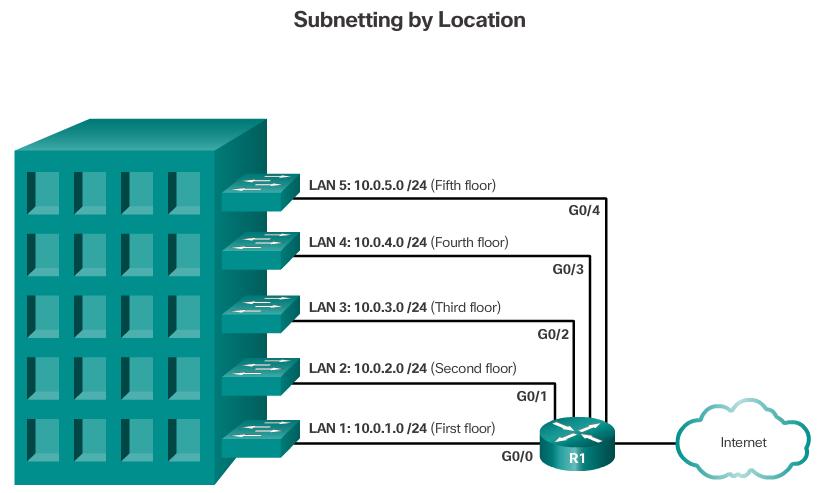
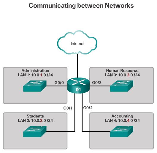
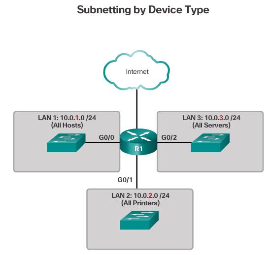
8 Reasons for Subnetting Subnetting reduces overall network traffic and improves network performance. It also enables an administrator to implement security policies such as which subnets are allowed or not allowed to communicate together. There are various ways of using subnets to help manage network devices. Network administrators can group devices and services into subnets that are determined by: Location, such as floors in a building (Figure 1) Organizational unit (Figure 2) Device type (Figure 3) Any other division that makes sense for the network. Notice in each figure, the subnets use longer prefix lengths to identify networks. This chapter describes how subnetting is performed. Understanding how to subnet networks is a fundamental skill that all network administrators must develop. Various methods have been developed to help understand this process. This chapter will focus on looking at the binary method. Although a little overwhelming at first, focus and pay close attention to the detail and with practice, subnetting should become easier.

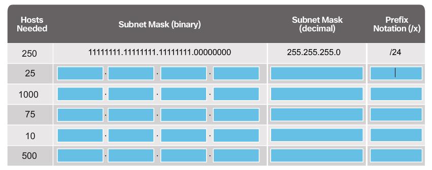
9 Octet Boundaries Every interface on a router is connected to a network. The IP address and subnet mask configured on the router interface are used to identify the specific broadcast domain. Recall that the prefix length and the subnet mask are different ways of identifying the network portion of an address. IPv4 subnets are created by using one or more of the host bits as network bits. This is done by extending the subnet mask to borrow some of the bits from the host portion of the address to create additional network bits. The more host bits that are borrowed, the more subnets that can be defined. Networks are most easily subnetted at the octet boundary of /8, /16, and /24. The table in the figure identifies these prefix lengths, equivalent subnet masks, the network and host bits, and the number of hosts each subnet can connect. Notice that using longer prefix lengths decreases the number of hosts per subnet.
10

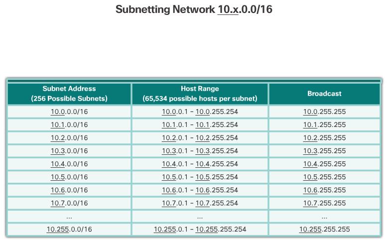
11 Subnetting on the Octet Boundary To understand how subnetting on the octet boundary can be useful, consider the following example. Assume an enterprise has chosen the private address /8 as its internal network address. That network address can connect 16,777,214 hosts in one broadcast domain. Obviously, this is not ideal. The enterprise could further subnet the /8 address at the octet boundary of /16 as shown in Figure 1. This would provide the enterprise the ability to define up to 256 subnets (i.e., / /16) with each subnet capable of connecting 65,534 hosts. Notice how the first two octets identify the network portion of the address while the last two octets are for host IP addresses. Alternatively, the enterprise could choose to subnet at the /24 octet boundary as shown in Figure 2. This would enable the enterprise to define 65,536 subnets each capable of connecting 254 hosts. The /24 boundary is very popular in subnetting because it accommodates a reasonable number of hosts and conveniently subnets at the octet boundary.

12 Classless Subnetting The examples seen so far borrowed host bits from the common /8, /16, and /24 network prefixes. However, subnets can borrow bits from any host bit position to create other masks. For instance, a /24 network address is commonly subnetted using longer prefix lengths by borrowing bits from the fourth octet. This provides the administrator with additional flexibility when assigning network addresses to a smaller number of end devices. As shown in the figure: /25 row - Borrowing 1 bit from the fourth octet creates 2 subnets supporting 126 hosts each. /26 row - Borrowing 2 bits creates 4 subnets supporting 62 hosts each. /27 row Borrowing 3 bits creates 8 subnets supporting 30 hosts each. /28 row Borrowing 4 bits creates 16 subnets supporting 14 hosts each. /29 row Borrowing 5 bits creates 32 subnets supporting 6 hosts each. /30 row Borrowing 6 bits creates 64 subnets supporting 2 hosts each. For each bit borrowed in the fourth octet, the number of subnetworks available is doubled while reducing the number of host addresses per subnet.

13 Video Demonstration The Subnet Mask Click Play to view an explanation of the subnet mask. Click here to read the transcript of this video.
14 Video Demonstration Subnetting with the Magic Number Click Play to view an explanation of the magic number. Click here to read the transcript of this video.
15

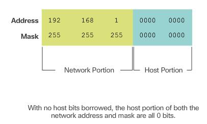
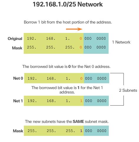
16 Classless Subnetting Example To understand how subnetting at a classless level can be useful, consider the following examples. Consider the private network address /24 shown in Figure 1. The first three octets are displayed in decimal, while the last octet is displayed in binary. The reason for this is because we will be borrowing bits from the last octet to create subnets of the /24 network. The subnet mask is as indicated by the /24 prefix length. This identifies the first three octets as the network portion and the remaining 8 bits in the last octet as the host portion. Without subnetting, this network supports a single LAN interface providing 254 host IP addresses. If an additional LAN is needed, the network would need to be subnetted. In Figure 2, 1 bit is borrowed from the most significant bit (leftmost bit) in the host portion, thus extending the network portion to 25 bits or /25. This enables the creation of two subnets. Figure 3 displays the two subnets: /25 and /25. The two subnets are derived from changing the value of the bit borrowed to either 0 or 1. Because the bit borrowed is the 128 bit, the decimal value of the fourth octet for the 2nd subnet is 128. Figure 4 displays the resulting subnet mask for both networks. Notice how it uses a 1 in the borrowed bit position to indicate that this bit is now part of the network portion. Figure 5 displays the dotted decimal representation of the two subnet addresses and their common subnet mask. Because one bit has been borrowed, the subnet mask for each subnet is or /25.
17
18

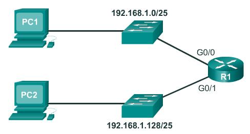
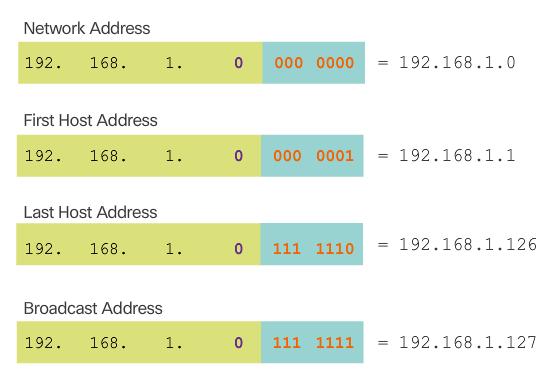
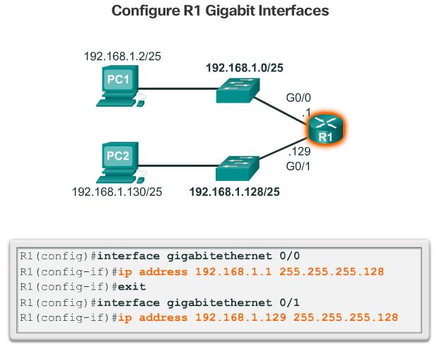
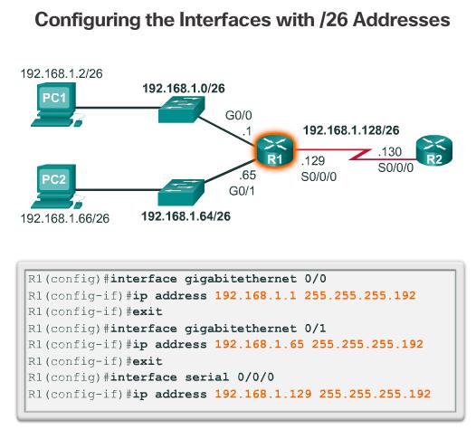
19 Creating 2 Subnets To see how a /25 subnet is applied in a network; consider the topology in Figure 1. R1 has two LAN segments attached to its GigabitEthernet interfaces. Each LAN is assigned one of the subnets. Figure 2 displays the important addresses of the first subnet, /25. Notice how the: Network address is and contains all 0 bits in the host portion of the address. First host address is and contains all 0 bits plus a right-most 1 bit in the host portion of the address. Last host address is and contains all 1 bits plus a right-most 0 bit in the host portion of the address. Broadcast address is and contains all 1 bits in the host portion of the address. Figure 3 displays the important addresses of the second subnet, /25. Router interfaces must be assigned an IP address within the valid host range for the assigned subnet. This is the address that hosts on that network will use as their default gateway. A very common practice is to use the first or last available address in a network range for the router interface address. Figure 4
20 shows the configuration for R1 s interfaces with the first IP address for their respective subnets using the ip address interface configuration command. Hosts on each subnet must be configured with an IP address and default gateway. Figure 5 displays the IP configuration for PC2 host on the /25 network. Notice that the default gateway IP address is the address configured on the G0/1 interface of R1, , and the subnet mask is

21 Video Demonstration Creating Two Equal-Sized Subnets Click Play to view a demonstration of creating two equal-sized subnets. Click here to read the transcript of this video.
22

23 Subnetting Formulas To calculate the number of subnets that can be created from the bits borrowed, use the formula displayed in Figure 1. Figure 2 displays the possible number of subnets that can be created when borrowing 1, 2, 3, 4, 5, or 6 bits. Note: The last two bits cannot be borrowed from the last octet because there would be no host addresses available. Therefore, the longest prefix length possible when subnetting is /30 or To calculate the number of hosts that can be supported, use the formula displayed in Figure 3. There are two subnet addresses that cannot be assigned to a host, the network address and the broadcast address, so we must subtract 2. As shown in Figure 4, there are 7 host bits remaining, so the calculation is 2^7 = = 126. This means that each of the subnets has 126 valid host addresses. Therefore, borrowing 1 host bit toward the network results in creating 2 subnets, and each subnet can have a total of 126 hosts assigned.
24
25

26 Creating 4 Subnets
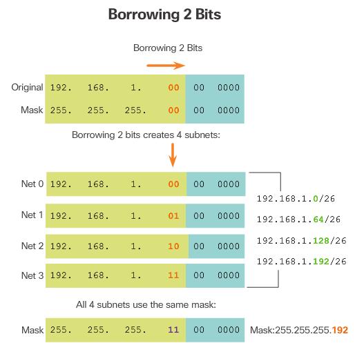
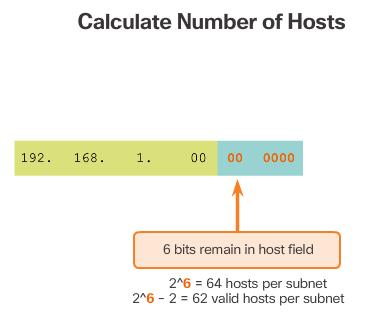
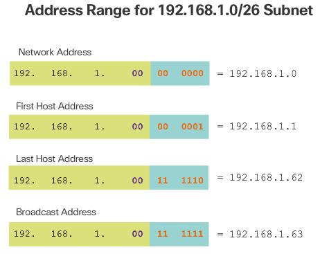
27 Now consider the network topology shown in Figure 1. The enterprise is using the private network address /24 range and requires three subnets. Borrowing a single bit only provided 2 subnets; therefore, another host bit must be borrowed as shown in Figure 2. Using the 2^n formula for two borrowed bits results in 2^2 = 4 subnets. The specifics of the four subnets are shown in Figure 3. The resulting subnet mask of /26 or is used by all four subnets. To calculate the number of hosts, examine the last octet as shown in Figure 4. After borrowing 2 bits for the subnet, there are 6 host bits remaining. Apply the host calculation formula 2^n - 2 as shown to reveal that each subnet can support 62 host addresses. The significant addresses of the first subnet (i.e., Net 0) are displayed in Figure 5. Only the first three subnets are required because there are only three interfaces. Figure 6 displays the specifics of the first three subnets that will be used to satisfy the topology in Figure 1. Finally, Figure 7 applies the first valid host address from each subnet to the respective R1 LAN interface.

28 Video Demonstration Creating Four Equal-Sized Subnets Click Play to view a demonstration of creating four equal-sized subnets. Click here to read the transcript of this video.
29 Video Demonstration Creating Eight Equal-Sized Subnets Click Play to view a demonstration of creating eight equal-sized subnets. Click here to read the transcript of this video.


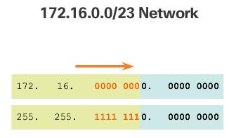
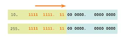
30 Creating Subnets with a /16 prefix In a situation requiring a larger number of subnets, an IP network is required that has more hosts bits to borrow from. For example, the network address has a default mask of , or /16. This address has 16 bits in the network portion and 16 bits in the host portion. The 16 bits in the host portion are available to borrow for creating subnets. The table in the figure highlights all the possible scenarios for subnetting a /16 prefix. Although a complete memorization of the table is not required, it is suggested that you gain a good understanding of how each value in the table is generated. Do not let the size of the table intimidate you. The reason it is big is because it has 8 additional bits that can be borrowed, and, therefore, the number of subnets and hosts are simply larger.
31

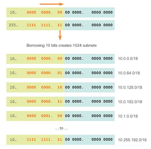
32 Creating 100 Subnets with a /16 Network Consider a large enterprise that requires at least 100 subnets and has chosen the private address /16 as its internal network address. When borrowing bits from a /16 address, start borrowing bits in the third octet, going from left to right. Borrow a single bit at a time until the number of bits necessary to create 100 subnets is reached. Figure 1 displays the number of subnets that can be created when borrowing bits from the third octet and the fourth octet. Notice there is now up to 14 host bits that can be borrowed. To satisfy the requirements of the enterprise, 7 bits (i.e., 2^7 = 128 subnets) would need to be borrowed, as shown in Figure 2. Recall that the subnet mask must change to reflect the borrowed bits. In this example, when 7 bits are borrowed, the mask is extended 7 bits into the third octet. In decimal, the mask is represented as , or a /23 prefix, because the third octet is in binary and the fourth octet is in binary. Figure 3 displays the resulting subnets from /23 up to /23.
33
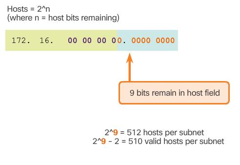
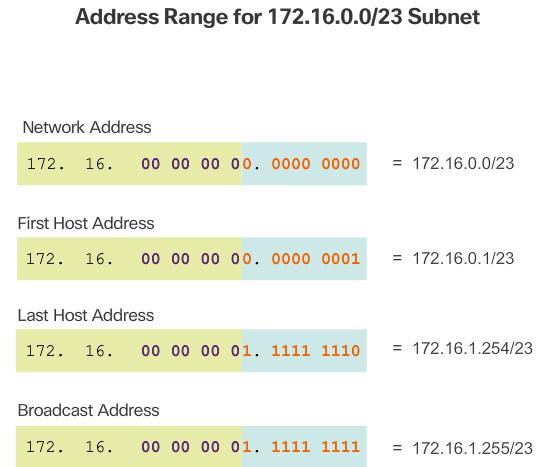
34 Calculating the Hosts To calculate the number of hosts each subnet can support, examine the third and fourth octet. After borrowing 7 bits for the subnet, there is one host bit remaining in the third octet and 8 host bits remaining in the fourth octet for a total of 9 bits that were not borrowed. Apply the host calculation formula as shown in Figure 1. There are only 510 host addresses that are available for each /23 subnet. As shown in Figure 2, the first host address for the first subnet is , and the last host address is
35 Video Demonstration Creating One Hundred Equal-Sized Subnets Click Play to view a demonstration of creating 100 equal-sized subnets. Click here to read the transcript of this video.
36
37
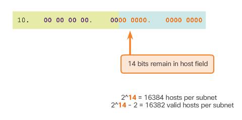
38 Creating 1000 Subnets with a /8 Network Some organizations, such as small service providers or large enterprises, may need even more subnets. Take, for example, a small ISP that requires 1000 subnets for its clients. Each client will need plenty of space in the host portion to create their own subnets. The network address has a default subnet mask of or /8. This means there are 8 bits in the network portion and 24 host bits available to borrow toward subnetting. Therefore, the small ISP will subnet the /8 network. As always, in order to create subnets we must borrow bits from the host portion of the IP address of the existing internetwork. Starting from the left to the right with the first available host bit, we will borrow a single bit at a time until we reach the number of bits necessary to create 1000 subnets. As shown in Figure 1, we need to borrow 10 bits to create 1024 subnets. Specifically, we need to borrow the 8 bits in the second octet and 2 additional bits from the third octet. Figure 2 displays the network address and the resulting subnet mask which converts to or a /18 prefix. Figure 3 displays the resulting subnets of borrowing 10 bits creating subnets from /18 to /18. Figure 4 displays that 14 host bits were not borrowed, therefore, 2^14-2 = This indicates that each of the 1000 subnets can support up to 16,382 hosts. Figure 5 displays the specifics of the first subnet.
39 Video Demonstration Subnetting Across Multiple Octets Click Play to view an explanation of using the magic number across classful bit boundaries. Click here to read the transcript of this video.

40 Subnetting Based on Host Requirements There are two considerations when planning subnets: the number of host addresses required for each network the number of individual subnets needed The table in the figure displays the specifics for subnetting a /24 network. Notice how there is an inverse relationship between the number of subnets and the number of hosts. The more bits borrowed to create subnets, the fewer host bits available. If more host addresses are needed, more host bits are required, resulting in fewer subnets. The number of host addresses required in the largest subnet will determine how many bits must be left in the host portion. Recall that two of the addresses cannot be used, so the usable number of addresses can be calculated as 2^n-2.

41 Subnetting Based on Network Requirements Sometimes a certain number of subnets is required, with less emphasis on the number of host addresses per subnet. This may be the case if an organization chooses to separate their network traffic based on internal structure or department setup, as shown in the figure. For example, an organization may choose to put all host devices used by employees in the Engineering department in one network, and all host devices used by management in a separate network. In this case, the number of subnets is most important in determining how many bits to borrow. Recall the number of subnets created when bits are borrowed can be calculated using the formula 2^n (where n is the number of bits borrowed). The key is to balance the number of subnets needed and the number of hosts required for the largest subnet. The more bits borrowed to create additional subnets means fewer hosts available per subnet.
42
43
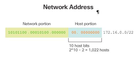
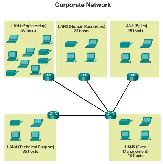
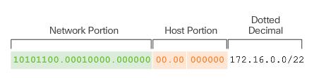
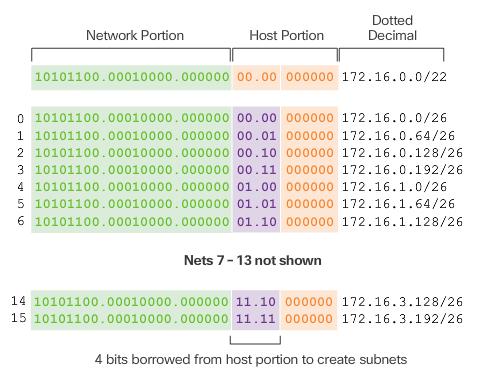
44 Network Requirement Example Network administrators must devise the network addressing scheme to accommodate the maximum number of hosts for each network and the number of subnets. The addressing scheme should allow for growth in the both the number of host addresses per subnet and the total number of subnets. In this example, corporate headquarters has allocated a private network address of /22 (10 host bits) to a branch location. As shown in Figure 1, this will provide 1,022 host addresses. The topology for the branch locations, shown in Figure 2, consists of 5 LAN segments and 4 internetwork connections between routers. Therefore, 9 subnets are required. The largest subnet requires 40 hosts. The /22 network address has 10 host bits as shown in Figure 3. Because the largest subnet requires 40 hosts, a minimum of 6 host bits are needed to provide addressing for 40 hosts. This is determined by using this formula: 2^6 2 = 62 hosts. Using the formula for determining subnets, results in 16 subnets: 2^4 = 16. Because the example internetwork requires 9 subnets this will meet the requirement and allow for some additional growth. Therefore, the first 4 host bits can be used to allocate subnets, as shown in Figure 4. When 4 bits are borrowed, the new prefix length is /26 with a subnet mask of As shown in Figure 5, the subnets can be assigned to the LAN segments and router-to-router connections.
45 This topic concludes with four activities to practice subnetting. The Chapter Appendix includes additional practice activities.
46
47

48 Lab - Calculating IPv4 Subnets In this lab, you will complete the following objectives: Part 1: Determine IPv4 Address Subnetting Part 2: Calculate IPv4 Address Subnetting Lab - Calculating IPv4 Subnets

49 Packet Tracer - Subnetting Scenario 1 In this activity, you are given the network address of /24 to subnet and provide the IP addressing for the network shown in the topology. Each LAN in the network requires enough space for, at least, 25 addresses for end devices, the switch and the router. The connection between R1 to R2 will require an IP address for each end of the link. Packet Tracer - Subnetting Scenario 1 Instructions Packet Tracer - Subnetting Scenario 1 - PKA Note: Refer to the Chapter Appendix for Subnetting Scenario 2.

50 Lab Designing and Implementing a Subnetted IPv4 Addressing Scheme In this lab, you will complete the following objectives: Part 1: Design a Network Subnetting Scheme Part 2: Configure the Devices Part 3: Test and Troubleshoot the Network Lab - Designing and Implementing a Subnetted IPv4 Addressing Scheme
51

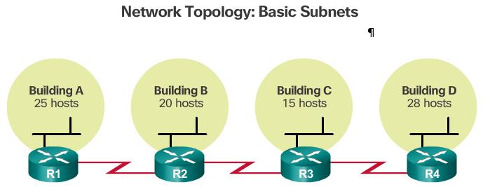
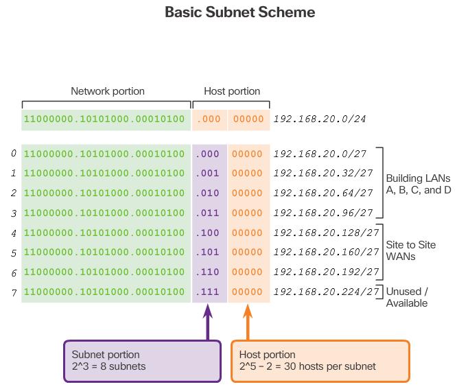
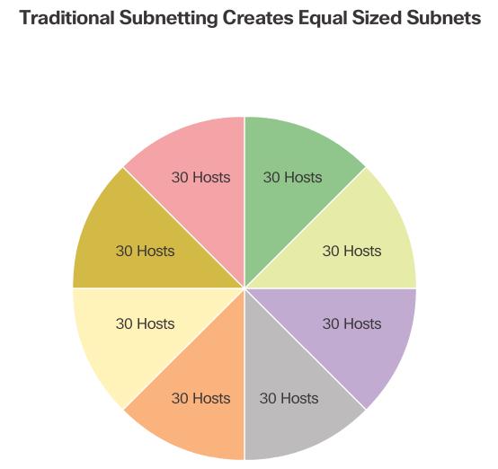
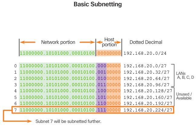
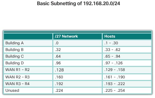
52 Traditional Subnetting Wastes Addresses Using traditional subnetting, the same number of addresses is allocated for each subnet. If all the subnets have the same requirements for the number of hosts, these fixed size address blocks would be efficient. However, most often that is not the case. For example, the topology shown in Figure 1 requires seven subnets, one for each of the four LANs, and one for each of the three WAN connections between routers. Using traditional subnetting with the given address of /24, 3 bits can be borrowed from the host portion in the last octet to meet the subnet requirement of seven subnets. As shown in Figure 2, borrowing 3 bits creates 8 subnets and leaves 5 host bits with 30 usable hosts per subnet. This scheme creates the needed subnets and meets the host requirement of the largest LAN. Although this traditional subnetting meets the needs of the largest LAN and divides the address space into an adequate number of subnets, it results in significant waste of unused addresses. For example, only two addresses are needed in each subnet for the three WAN links. Because each subnet has 30 usable addresses, there are 28 unused addresses in each of these subnets. As shown in Figure 3, this results in 84 unused addresses (28x3). Further, this limits future growth by reducing the total number of subnets available. This inefficient use of addresses is characteristic of traditional subnetting. Applying a traditional subnetting scheme to this scenario is not very efficient and is wasteful. Subnetting a subnet, or using Variable Length Subnet Mask (VLSM), was designed to avoid wasting addresses.
53

54 Variable Length Subnet Masks In all of the previous examples of subnetting, notice that the same subnet mask was applied for all the subnets. This means that each subnet has the same number of available host addresses. As illustrated in Figure 1, traditional subnetting creates subnets of equal size. Each subnet in a traditional scheme uses the same subnet mask. As shown in Figure 2, VLSM allows a network space to be divided into unequal parts. With VLSM, the subnet mask will vary depending on how many bits have been borrowed for a particular subnet, thus the variable part of the VLSM. VLSM subnetting is similar to traditional subnetting in that bits are borrowed to create subnets. The formulas to calculate the number of hosts per subnet and the number of subnets created still apply. The difference is that subnetting is not a single pass activity. With VLSM, the network is first subnetted, and then the subnets are subnetted again. This process can be repeated multiple times to create subnets of various sizes. Note: When using VLSM, always begin by satisfying the host requirements of the largest subnet. Continue subnetting until the host requirements of the smallest subnet are satisfied.
55
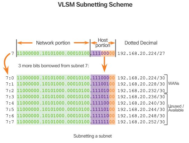
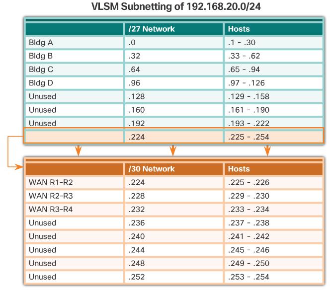
56 Basic VLSM To better understand the VLSM process, go back to the previous example, shown in Figure 1. The network /24 was subnetted into eight equal-sized subnets. Seven of the eight subnets were allocated. Four subnets were used for the LANs and three subnets for the WAN connections between the routers. Recall that the wasted address space was in the subnets used for the WAN connections, because those subnets required only two usable addresses: one for each router interface. To avoid this waste, VLSM can be used to create smaller subnets for the WAN connections. To create smaller subnets for the WAN links, one of the subnets will be divided. In this example, the last subnet, /27, will be further subnetted. Recall that when the number of needed host addresses is known, the formula 2^n-2 (where n equals the number of host bits remaining) can be used. To provide two usable addresses, 2 host bits must be left in the host portion. Because there are 5 host bits in the subnetted /27 address space, 3 more bits can be borrowed, leaving 2 bits in the host portion, as shown in Figure 2. The calculations at this point are exactly the same as those used for traditional subnetting. The bits are borrowed, and the subnet ranges are determined. This VLSM subnetting scheme reduces the number of addresses per subnet to a size appropriate for the WANs. Subnetting subnet 7 for WANs, allows subnets 4, 5, and 6 to be available for future networks, as well as 5 additional subnets available for WANs.
57 Video Demonstration Basic VLSM Click Play to view a demonstration of basic VLSM techniques. Click here to read the transcript of this video.
58
59
60

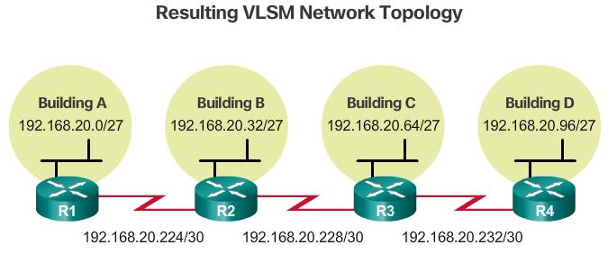
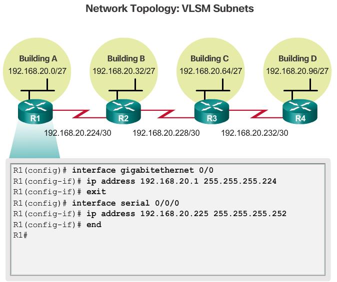
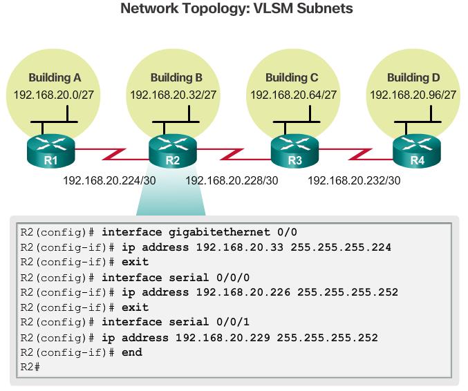
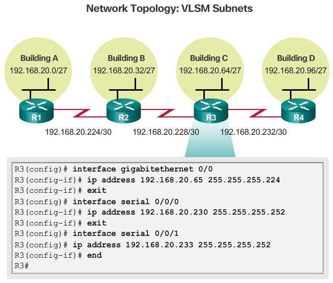
61 VLSM in Practice Using the VLSM subnets, the LAN and WAN segments can be addressed without unnecessary waste. As shown in Figure 1, the hosts in each of the LANs will be assigned a valid host address with the range for that subnet and /27 mask. Each of the four routers will have a LAN interface with a /27 subnet and a one or more serial interfaces with a /30 subnet. Using a common addressing scheme, the first host IPv4 address for each subnet is assigned to the LAN interface of the router. The WAN interfaces of the routers are assigned the IP addresses and mask for the /30 subnets. Figures 2-5 show the interface configuration for each of the routers. Hosts on each subnet will have a host IPv4 address from the range of host addresses for that subnet and an appropriate mask. Hosts will use the address of the attached router LAN interface as the default gateway address. Default gateway for Building A hosts ( /27) will be Default gateway for Building B hosts ( /27) will be Default gateway for Building C hosts ( /27) will be
62 Default gateway for Building D hosts ( /27) will be
63
64 VLSM Chart An addressing chart can be used to identify which blocks of addresses are available for use and which ones are already assigned, as shown in Figure 1. This method helps to prevent assigning addresses that have already been allocated. In order to use the address space more efficiently, /30 subnets are created for WAN links, as shown in the VLSM chart in Figure 2. To keep the unused blocks of addresses together in a block of contiguous address space, the last /27 subnet was further subnetted to create the /30 subnets. The first 3 subnets were assigned to WAN links. Designing the addressing scheme in this way leaves 3 unused, contiguous /27 subnets and 5 unused contiguous /30 subnets.
65 Video Demonstration VLSM Example Click Play to view a demonstration of VLSM subnetting. Click here to read the transcript of this video.
66

67 Network Address Planning As shown in the figure, the allocation of network layer address space within the corporate network needs to be well designed. Address assignment should not be random. Planning network subnets requires examination of both the needs of an organization s network usage, and how the subnets will be structured. Performing a network requirement study is the starting point. This means looking at the entire network and determining the main sections of the network and how they will be segmented. The address plan includes determining the needs of each subnet in terms of size, how many hosts per subnet, how host addresses will be assigned, which hosts will require static IP addresses, and which hosts can use DHCP for obtaining their addressing information. The size of the subnet involves planning the number of hosts that will require IP host addresses in each subnet of the subdivided private network. For example, in a campus network design, you might consider how many hosts are needed in the Administrative LAN, how many in the Faculty LAN, and how many in the Student LAN. In a home network, a consideration might be done by the number of hosts in the Main House LAN and the number of hosts in the Home Office LAN. As discussed earlier, the private IP address range used on a LAN is the choice of the network administrator and needs careful consideration to be sure that enough host addresses will be available for the currently known hosts and for future expansion. Remember the private IP address ranges are:
68 with a subnet mask of or / with a subnet mask of or / with a subnet mask of or /16 Knowing your IP address requirements will determine the range or ranges of host addresses you implement. Subnetting the selected private IP address space will provide the host addresses to cover your network needs. Public addresses used to connect to the Internet are typically allocated from a service provider. So, while the same principles for subnetting would apply, this is not generally the responsibility of the organization s network administrator.

69 Planning to Address the Network Three primary considerations for planning address allocation are displayed in the figure. Preventing the duplication of addresses refers to the fact that each host in an internetwork must have a unique address. Without the proper planning and documentation, an address could be assigned to more than one host, resulting in access issues for both hosts. Providing and controlling access refers to the fact that some hosts, such as servers, provide resources to internal hosts as well as to external hosts. The Layer 3 address assigned to a server can be used to control access to that server. If, however, the address is randomly assigned and not well documented, controlling access is more difficult. Monitoring security and performance of hosts means network traffic is examined for source IP addresses that are generating or receiving excessive packets. If there is proper planning and documentation of the network addressing, problematic network devices should easily be found.
. This reduces the burden on network support staff and virtually eliminates entry errors. As well, addresses are only leased for a period of time.")
70 Assigning Addresses to Devices Within a network, there are different types of devices that require addresses, including: End user clients Most networks allocate addresses dynamically using Dynamic Host Configuration Protocol (DHCP). This reduces the burden on network support staff and virtually eliminates entry errors. As well, addresses are only leased for a period of time. Changing the subnetting scheme means that the DHCP server needs to be reconfigured, and the clients must renew their IP addresses. Servers and peripherals These should have a predictable static IP address. Use a consistent numbering system for these devices. Servers that are accessible from the Internet In many networks, servers must be made available to the remote users. In most cases, these servers are assigned private addresses internally, and the router or firewall at the perimeter of the network must be configured to translate the internal address into a public address. Intermediary devices These devices are assigned addresses for network management, monitoring, and security. Because we must know how to communicate with intermediary devices, they should have predictable, statically assigned addresses. Gateway - Routers and firewall devices have an IP address assigned to each interface which serves as the gateway for the hosts in that network. Typically, the router interface uses either the lowest or highest address in the network. The table in the figure provides a sample of address allocation for a small network.
71 When developing an IP addressing scheme, it is generally recommended to have a set pattern of how addresses are allocated to each type of device. This benefits administrators when adding and removing devices, filtering traffic based on IP, as well as simplifying documentation.
72 Packet Tracer Designing and Implementing a VLSM Addressing Scheme In this activity, you are given a /24 network address to use to design a VLSM addressing scheme. Based on a set of requirements, you will assign subnets and addressing, configure devices and verify connectivity. Packet Tracer - Designing and Implementing a VLSM Addressing Scheme Instructions Packet Tracer - Designing and Implementing a VLSM Addressing Scheme PKA

73 Lab Designing and Implementing a VLSM Addressing Scheme In this lab, you will complete the following objectives: Part 1: Examine Network Requirements Part 2: Design the VLSM Address Scheme Part 3: Cable and Configure the IPv4 Network Lab - Designing and Implementing a VLSM Addressing Scheme
74


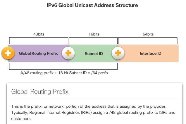
75 The IPv6 Global Unicast Address IPv6 subnetting requires a different approach than IPv4 subnetting. The primary reason is that with IPv6 there are so many addresses, that the reason for subnetting is completely different. Refer to the figure for a quick review of the structure of an IPv6 global unicast address. IPv4 subnetting is not only about limiting broadcast domains but is also about managing address scarcity. Determining the subnet mask and the use of VLSM is done to help conserve IPv4 addresses. IPv6 subnetting is not concerned with conserving address space. The subnet ID includes more than enough subnets. IPv6 subnetting is about building an addressing hierarchy based on the number of subnetworks needed. Recall that there are two types of assignable IPv6 addresses. An IPv6 link-local address is never subnetted because it exists only on the local link. However, an IPv6 global unicast address can be subnetted. The IPv6 global unicast address normally consists of a /48 global routing prefix, a 16 bit subnet ID, and a 64 bit interface ID.

76 Subnetting Using the Subnet ID The 16 bit subnet ID section of the IPv6 global unicast address can be used by an organization to create internal subnets. The subnet ID provides more than enough subnets and host support than will ever be needed in one subnet. For instance, the 16 bit section can: Create up to 65,536 /64 subnets. This does not include the possibility of borrowing any bits from the interface ID of the address. Support up to 18 quintillion host IPv6 addresses per subnet (i.e., 18,000,000,000,000,000,000). Note: Subnetting into the 64 bit Interface ID (or host portion) is also possible but it is rarely required. IPv6 subnetting is also easier to implement than IPv4, because there is no conversion to binary required. To determine the next available subnet, just count up in hexadecimal. For example, assume an organization has been assigned the 2001:0DB8:ACAD::/48 global routing prefix with a 16 bit subnet ID. This would allow the organization to create /64 subnets, as shown in the figure. Notice how the global routing prefix is the same for all subnets. Only the subnet ID hextet is incremented in hexadecimal for each subnet.
77
78

79 IPv6 Subnet Allocation With over 65,000 subnets to choose from, the task of the network administrator becomes one of designing a logical scheme to address the network. As shown in Figure 1, the example topology will require subnets for each LAN as well as for the WAN link between R1 and R2. Unlike the example for IPv4, with IPv6 the WAN link subnet will not be subnetted further. Although this may waste addresses, that is not a concern when using IPv6. As shown in Figure 2, the allocation of five IPv6 subnets, with the subnet ID field 0001 through 0005 will be used for this example. Each /64 subnet will provide more addresses than will ever be needed. As shown in Figure 3, each LAN segment and the WAN link is assigned a /64 subnet. Similar to configuring IPv4, Figure 4 shows that each of the router interfaces has been configured to be on a different IPv6 subnet. Refer the Chapter Appendix for more information subnetting IPv6 into the interface ID.
80 Packet Tracer Implementing a Subnetted IPv6 Addressing Scheme Your network administrator wants you to assign five /64 IPv6 subnets to the network shown in the topology. Your job is to determine the IPv6 subnets, assign IPv6 addresses to the routers and set the PCs to automatically receive IPv6 addressing. Your final step is to verify connectivity between IPv6 hosts. Packet Tracer - Implementing a Subnetted IPv6 Addressing Scheme Instructions Packet Tracer - Implementing a Subnetted IPv6 Addressing Scheme - PKA

81 Class Activity Can you call me now? Can you call me now? Note: This activity may be completed individually or in small/large groups using Packet Tracer software. You are setting up a dedicated, computer addressing scheme for patient rooms in a hospital. The switch will be centrally located in the nurses station, as each of the five rooms will be wired so that patients can just connect to a RJ-45 port built into the wall of their room. Devise a physical and logical topology for only one of the six floors using the following addressing scheme requirements: There are six floors, with five patient rooms on each floor, for a total of thirty connections. Each room needs a network connection. Subnetting must be incorporated into your scheme. Use one router, one switch, and five host stations for addressing purposes.
82 Validate that all PCs can connect to the hospital s in-house services. Keep a copy of your scheme to share later with the class or learning community. Be prepared to explain how subnetting, unicasts, multicasts, and broadcasts would be incorporated, and where your addressing scheme could be used. Class Activity - Can you call me now? Instructions
83 Packet Tracer Skills Integration Challenge As a network technician familiar with IPv4 and IPv6 addressing implementations, you are now ready to take an existing network infrastructure and apply your knowledge and skills to finalize the configuration. The network administrator has already configured some commands on the routers. Do not erase or modify those configurations. Your task is to complete the IPv4 and IPv6 addressing scheme, implement IPv4 and IPv6 addressing, and verify connectivity. Packet Tracer - Skills Integration Challenge Instructions Packet Tracer - Skills Integration Challenge - PKA

84 Chapter 8: Subnetting IP Networks The process of segmenting a network by dividing it into to multiple smaller network spaces is called subnetting. Every network address has a valid range of host addresses. All devices attached to the same network will have an IPv4 host address for that network and a common subnet mask or network prefix. Traffic can be forwarded between hosts directly if they are on the same subnet. Traffic cannot be forwarded between subnets without the use of a router. To determine if traffic is local or remote, the router uses the subnet mask. The prefix and the subnet mask are different ways of representing the same thing - the network portion of an address. IPv4 subnets are created by using one or more of the host bits as network bits. Two very important factors that will lead to the determination of the IP address block with the subnet mask are the number of subnets required, and the maximum number of hosts needed per subnet. There is an inverse relationship between the number of subnets and the number of hosts. The more bits that are borrowed to create subnets, the fewer host bits that are available; therefore, there are fewer hosts per subnet. The formula 2^n (where n is the number of host bits remaining) is used to calculate how many addresses will be available on each subnet. However, the network address and broadcast address within a range are not useable. Therefore, to calculate the useable number of addresses, the calculation 2^n-2 is required. Subnetting a subnet, or using Variable Length Subnet Mask (VLSM), was designed to avoid wasting addresses. IPv6 subnetting requires a different approach than IPv4 subnetting. An IPv6 address space is not subnetted to conserve addresses; rather it is subnetted to support a hierarchical, logical design of the
85 network. So, while IPv4 subnetting is about managing address scarcity, IPv6 subnetting is about building an addressing hierarchy based on the number of routers and the networks they support. Careful planning is required to make best use of the available address space. Size, location, use, and access requirements are all considerations in the address planning process. After it is implemented, an IP network needs to be tested to verify its connectivity and operational performance.
Chapter 8: Subnetting IP Networks CCENT Routing and Switching Introduction to Networks v6.0
 Chapter 8: Subnetting IP Networks CCENT Routing and Switching Introduction to Networks v6.0 CCNET v6 13 Chapter 8 - Sections & Objectives 8.1 Subnetting an IPv4 Network Explain how subnetting segments
Chapter 9: Subnetting IP Networks
 Chapter 9: Subnetting IP Networks Network Segmentation Reasons for Subnetting Subnetting is the process of segmenting a network into multiple smaller network spaces called subnetworks or subnets. The purpose
CCNA Exploration Network Fundamentals. Chapter 06 Addressing the Network IPv4
 CCNA Exploration Network Fundamentals Chapter 06 Addressing the Network IPv4 Updated: 20/05/2008 1 6.0.1 Introduction Addressing is a key function of Network layer protocols that enables data communication
CCNA Exploration Network Fundamentals. Chapter 10 Planning and Cabling Networks
 CCNA Exploration Network Fundamentals Chapter 10 Planning and Cabling Networks Updated: 15/07/2008 1 10.0.1 Introduction 2 10.0.1 Introduction The following have been covered in previous chapters: considered
Lab 8 (IP Addressing)
") Islamic University of Gaza Faculty of engineering Computer Department. Computer Network Lab ECOM 4121 Prepared by : Eng. Eman Al- Kurdi Lab 8 (IP Addressing) Introduction: Each device on a network must
Islamic University of Gaza Faculty of engineering Computer Department. Computer Network Lab ECOM 4121 Prepared by : Eng. Eman Al- Kurdi Lab 8 (IP Addressing) Introduction: Each device on a network must
Linux System Administration
 IP Addressing Subnetting Objective At the conclusion of this module, the student will be able to: Describe how packets are routed from one network to another Describe the parts and classes of IPv4 address
FIGURE 3. Two-Level Internet Address Structure. FIGURE 4. Principle Classful IP Address Formats
 Classful IP Addressing When IP was first standardized in September 1981, the specification required that each system attached to an IP-based Internet be assigned a unique, 32-bit Internet address value.
Chapter 8: Subnetting IP networks. Introduction to Networks v5.1
 Chapter 8: Subnetting IP networks Introduction to Networks v5.1 8.0 Introduction 8.1 Subnetting an IPv4 Network 8.2 Addressing Schemes 8.3 Design Considerations for IPv6 8.4 Summary 2013 Cisco and/or its
Unit C - Network Addressing Objectives Purpose of an IP Address and Subnet Mask Purpose of an IP Address and Subnet Mask
 1 2 3 4 5 6 7 8 9 10 Unit C - Network Addressing Objectives Describe the purpose of an IP address and Subnet Mask and how they are used on the Internet. Describe the types of IP Addresses available. Describe
CCNA 1 Chapter 9 v5.0 Exam Answers 2013
 1 CCNA 1 Chapter 9 v5.0 Exam Answers 2013 How many broadcast domains are there? 1 2 3 4* 2 How many usable host addresses are there in the subnet 192.168.1.32/27? 32 30* 64 16 62 3 How many host addresses
Lecture 8 Network Layer: Logical addressing
 Data Communications ACOE412 Lecture 8 Network Layer: Logical addressing Spring 2009 1 0. Overview In this lecture we will cover the following topics: 14.Network Layer: Logical addressing 14.1 IPv4 Addresses
IP Addressing - Subnetting
 IP Addressing - Subnetting The Two Parts of an IP Address 32 Bits Prefix Host Prefix Length IP Address Classes Classes are now considered obsolete But you have to learn them because Everyone in the industry
Chapter 18 and 22. IPv4 Address. Data Communications and Networking
 University of Human Development College of Science and Technology Department of Information Technology Chapter 18 and 22 Data Communications and Networking IPv4 Address 1 Lecture Outline IPv4 Addressing
IP addresses and Subnetting
 Page 1 of 14 Safepipe Centre > Self-test courses > IP addresses and Subnetting IP addresses and Subnetting IP addresses & subnetting - an overview IP addresses What is an IP address? Classes of IP addresses
Internet Fundamentals
 Internet Fundamentals Lecture-10 IPv4 19.2 19-1 IPv4 ADDRESSES An IPv4 address is a 32-bit address that uniquely and universally defines the connection of a device (for example, a computer or a router)
Computer Networks Lecture -5- IPv4 Addresses. Dr. Abbas Abdulazeez
 Computer Networks Lecture -5- IPv4 Addresses Dr. Abbas Abdulazeez McGraw-Hill The McGraw-Hill Companies, Inc., 2000 OBJECTIVES: To introduce the concept of an address space in general and the address space
IP: Routing and Subnetting
 IP: outing and Network Protocols and Standards Autumn 2004-2005 Oct 28, 2004 CS573: Network Protocols and Standards 1 Issues in Addressing A large corporate/campus environment Large number of Local Area
Interconnecting Cisco Networking Devices Part 1
 ICND1 Interconnecting Cisco Networking Devices Part 1 Volume 2 Version 1.0 Student Guide Editorial, Production, and Web Services: 07.25.07 DISCLAIMER WARRANTY: THIS CONTENT IS BEING PROVIDED AS IS. CISCO
12 Advanced IP Addressing
 12 Advanced IP Addressing CERTIFICATION OBJECTIVES 12.01 Variable-Length Subnet Masking 12.02 Route Summarization Q&A Two-Minute Drill Self Test 2 Chapter 12: Advanced IP Addressing In Chapter 11, you
Chapter 3 - Implement an IP Addressing Scheme and IP Services to Meet Network Requirements for a Small Branch Office
 ExamForce.com 640-822 CCNA ICND Study Guide 31 Chapter 3 - Implement an IP Addressing Scheme and IP Services to Meet Network Requirements for a Small Branch Office Describe the need and role of addressing
Chapter 6. Variable Length Subnet Masking (VLSM) Classless Inter-Domain Routing (CIDR) CCNA2-1 Chapter 6
 Classless Inter-Domain Routing (CIDR) CCNA2-1 Chapter 6") Chapter 6 Variable Length Subnet Masking (VLSM) Classless Inter-Domain Routing (CIDR) CCNA2-1 Chapter 6 VLSM and CIDR Classful and Classless Addressing CCNA2-2 Chapter 6 Classful and Classless Routing
Chapter 6 Variable Length Subnet Masking (VLSM) Classless Inter-Domain Routing (CIDR) CCNA2-1 Chapter 6 VLSM and CIDR Classful and Classless Addressing CCNA2-2 Chapter 6 Classful and Classless Routing
The identifier used in the IP layer of the TCP/IP protocol suite to identify each device connected to the Internet is called the Internet address or
 CBCN4103 The identifier used in the IP layer of the TCP/IP protocol suite to identify each device connected to the Internet is called the Internet address or IP address. An IP address is a 32-bit address
Networking and IP Addressing TELECOMMUNICATIONS AND NETWORKING
 Networking and IP Addressing TELECOMMUNICATIONS AND NETWORKING Addressing Schemes FLAT 1.Used by Intranetworks 2.Used by Layer 2 3.Used in MAC address 4.Is assigned statically based on next available number
Chapter 19 Network Layer: Logical Addressing 19.1
 Chapter 19 Network Layer: Logical Addressing 19.1 Copyright The McGraw-Hill Companies, Inc. Permission required for reproduction or display. 19.2 IPv4 IPv4 addresses are 32 bit length. IPv4 addresses are
Al-Mustansiriyah University Fourth Year ( )
") What subnet and broadcast address is IP address 172.16.10.33, 255.255.255.224 (/27) a member of? Answer: The interesting octet is the fourth octet. 256-224=32 block size. Because 32+32=64 and 33 is between
What subnet and broadcast address is IP address 172.16.10.33, 255.255.255.224 (/27) a member of? Answer: The interesting octet is the fourth octet. 256-224=32 block size. Because 32+32=64 and 33 is between
Configuring IPv4 Addresses
 This chapter contains information about, and instructions for configuring IPv4 addresses on interfaces that are part of a networking device. Note All further references to IPv4 addresses in this document
Chapter 3 LAN Configuration
 Chapter 3 LAN Configuration This chapter describes how to configure the advanced LAN features of your ProSafe Dual WAN Gigabit Firewall with SSL & IPsec VPN. This chapter contains the following sections
Chapter 6 Addressing the Network- IPv4
 Chapter 6 Addressing the Network- IPv4 Objectives Explain the structure IP addressing and demonstrate the ability to convert between 8- bit binary and decimal numbers. Given an IPv4 address, classify by
Chapter 4: VLSM and Classless Inter Domain Routing. ITE PC v4.0 Chapter Cisco Systems, Inc. All rights reserved.
 Chapter 4: VLSM and Classless Inter Domain Routing 1 What will we Learn from chapter 4? Compare and contrast classful and classless IP addressing. Review VLSM and explain the benefits of classless IP addressing.
NETWORK LAYER: IP Addressing
 NETWORK LAYER: IP Addressing McGraw-Hill The McGraw-Hill Companies, Inc., 2004 2000 Position of network layer McGraw-Hill The McGraw-Hill Companies, Inc., 2004 Network layer duties McGraw-Hill The McGraw-Hill
OSI Network Layer. Chapter 5
 OSI Network Layer Network Fundamentals Chapter 5 Objectives Identify the role of the Network Layer, as it describes communication from one end device to another end device. Examine the most common Network
First the Basics Binary Arithmetic
 www.preplogic.com -00-4-679 First the Basics Binary Arithmetic If you understand how binary numbers work, you can skip this section and go to the next. But, if you don t, you need to spend a bit of time
Lab Subnetting Network Topologies (Instructor Version)
") (Instructor Version) Instructor Note: Red font color or Gray highlights indicate text that appears in the instructor copy only. Objectives Parts 1 to 5, for each network topology: Determine the number
(Instructor Version) Instructor Note: Red font color or Gray highlights indicate text that appears in the instructor copy only. Objectives Parts 1 to 5, for each network topology: Determine the number
1 Connectionless Routing
 UCSD DEPARTMENT OF COMPUTER SCIENCE CS123a Computer Networking, IP Addressing and Neighbor Routing In these we quickly give an overview of IP addressing and Neighbor Routing. Routing consists of: IP addressing
Packet Tracer - Subnet Scenario 2 (Instructor Version)
") (Instructor Version) Instructor Note: Red font color or Gray highlights indicate text that appears in the instructor copy only. Topology 2015 Cisco and/or its affiliates. All rights reserved. This document
(Instructor Version) Instructor Note: Red font color or Gray highlights indicate text that appears in the instructor copy only. Topology 2015 Cisco and/or its affiliates. All rights reserved. This document
Subnetting Study Guide
 Subnetting Study Guide Boson TCP/IP Cheat Sheet by Boson Software, LLC An octet is a binary number of 8 bits, with the lowest possible number being 00000000 and the highest possible number being 11111111,
CS118 Discussion, Week 6. Taqi
 CS118 Discussion, Week 6 Taqi 1 Outline Network Layer IP NAT DHCP Project 2 spec 2 Network layer: overview Basic functions for network layer Routing Forwarding Connection v.s. connection-less delivery
ICND1 v2.0 Interconnecting Cisco Networking Devices Part 1 CCENT & Part of CCNA Rout/Switch
 ICND1 v2.0 Interconnecting Cisco Networking Devices Part 1 CCENT & Part of CCNA Rout/Switch Course Length: 5 days Course Delivery: Traditional Classroom Online Live Course Overview Interconnecting Cisco
Full file at
 ch02 True/False Indicate whether the statement is true or false. 1. IP addresses have links to domain names to make it possible for users to identify and access resources on a network. 2. As a frame moves
6 Chapter 6. Figure 1 Required Unique Addresses
 6 Chapter 6 6.1 Public and Private IP Addresses The stability of the Internet depends directly on the uniqueness of publicly used network addresses. In Figure 1 Required Unique Addresses, there is an issue
Top-Down Network Design
 Top-Down Network Design Chapter Six Designing Models for Addressing and Naming Copyright 2010 Cisco Press & Priscilla Oppenheimer Guidelines for Addressing and Naming Use a structured model for addressing
Packet Tracer - Subnet Scenario 2 Topology
 Topology 2016 Cisco and/or its affiliates. All rights reserved. This document is Cisco Public. Page 1 of 5 Addressing Table Device Interface IP Address Subnet Mask Default Gateway G0/0 R1 S0/0/0 G0/0 S0/0/0
Subnetting Questions:
 Subnetting Questions: Question 1 You have been asked to come up with a subnet mask that will allow all three servers to be on the same network while providing the maximum number of subnets. Which network
CS 5520/ECE 5590NA: Network Architecture I Spring Lecture 10: IP Routing and Addressing Extensions
 CS 5520/ECE 5590NA: Network Architecture I Spring 2009 Lecture 10: IP Routing and Addressing Extensions This lecture provides discussion of the mechanisms used to route IP datagrams (Chapter 7). It also
SPLITTING IPV4 NETWORKS INTO SUBNETS (CLASS, CIDR, VLSM)
") SPLITTING IPV4 NETWORKS INTO SUBNETS (CLASS, CIDR, VLSM) LAB GUIDELINES 1. Lab Target. To study the principles, tools and techniques for dividing the ISP address block allocated to the enterprise into
SPLITTING IPV4 NETWORKS INTO SUBNETS (CLASS, CIDR, VLSM) LAB GUIDELINES 1. Lab Target. To study the principles, tools and techniques for dividing the ISP address block allocated to the enterprise into
Building the Routing Table. Introducing the Routing Table Directly Connected Networks Static Routing Dynamic Routing Routing Table Principles
 Building the Routing Table Introducing the Routing Table Directly Connected Networks Static Routing Dynamic Routing Routing Table Principles Introducing the Routing Table R1# show ip route Codes: C - connected,
Module 4. Planning the Addressing Structure
 Module 4 Planning the Addressing Structure Name 4.1.1 1. How many bits are in an IP address? 2. What is dotted decimal notation? 3. What is the parent part of an IP address? 4. What is the child part of
Engr. Joseph Ronald Canedo's Note 1
 Engr. Joseph Ronald Canedo's Note 1 IP Addressing & Subnetting Made Easy Working with IP Addresses Joseph Ronald Cañedo Introduction You can probably work with decimal numbers much easier than with the
IP Addressing and Subnetting
 IP Addressing and Subnetting Internet Layer The purpose of the Internet layer is to send packets from a network node and have them arrive at the destination node independent of the path taken. Internet
Binary Octet to Decimal Format Conversion
 IP Address An IP (Internet Protocol) address is a unique address that different computers on a computer network use to identify and communicate with one another. An IP address is used as an identifier
Interconnecting Cisco Network Devices Part 1 v2.0 (ICND 1)
") Interconnecting Cisco Network Devices Part 1 v2.0 (ICND 1) COURSE OVERVIEW: Interconnecting Cisco Networking Devices, Part 1 (ICND1) v2.0 is a five-day, instructor-led training course that teaches learners
Interconnecting Cisco Network Devices Part 1 v2.0 (ICND 1) COURSE OVERVIEW: Interconnecting Cisco Networking Devices, Part 1 (ICND1) v2.0 is a five-day, instructor-led training course that teaches learners
Note: This case study utilizes Packet Tracer. Please see the Chapter 4 Packet Tracer file located in Supplemental Materials.
 Part 1 Variable Length Subnet Mask (VLSM) Note: This case study utilizes Packet Tracer Please see the Chapter 4 Packet Tracer file located in Supplemental Materials An organization has been assigned the
Subnetting Questions with Detailed Answers: Subnetting Questions with Detailed Answers:
 Subnetting Questions with Detailed Answers: Subnetting Questions with Detailed Answers: These questions were designed to test your knowledge of subnetting. Hopefully, by the end of the worksheet, the exercise
IP Addresses McGraw-Hill The McGraw-Hill Companies, Inc., 2000
 IP Addresses The IP addresses are unique. An IPv4 address is a 32-bit address. An IPv6 address is a 128-bit address. The address space of IPv4 is 2 32 or 4,294,967,296. The address space of IPv6 is 2 128
PUCPR. Internet Protocol. Edgard Jamhour E N G L I S H S E M E S T E R
 PUCPR Internet Protocol Address Resolution and Routing Edgard Jamhour 2014 E N G L I S H S E M E S T E R 1. Address Resolution The IP address does not identify, indeed, a computer, but a network interface.
Guide to TCP/IP Fourth Edition. Chapter 2: IP Addressing and Related Topics
 Guide to TCP/IP Fourth Edition Chapter 2: IP Addressing and Related Topics Objectives Describe IP addressing, anatomy and structures, and addresses from a computer s point of view Recognize and describe
Lab - Designing and Implementing a Subnetted IPv4 Addressing Scheme
 Lab - Designing and Implementing a Subnetted IPv4 Addressing Scheme Topology Addressing Table Objectives Device Interface IP Address Subnet Mask Default Gateway R1 G00 NA G01 NA Lo0 Lo1 NA NA S1 VLAN 1
Chapter 2 Review Questions
 Chapter 2 Review Questions The following questions are designed to test your understanding of this chapter s material. For more information on how to get additional questions, please see www.lammle.com/ccn
Interconnecting Cisco Networking Devices Part 1 ICND1
 Interconnecting Cisco Networking Devices Part 1 ICND1 Course Length: 5 days Course Delivery: Traditional Classroom Online Live Course Overview Interconnecting Cisco Networking Devices, Part 1 (ICND1) v3.0
Data Communication & Computer Networks Week # 13
 Data Communication & Computer Networks Week # 13 M.Nadeem Akhtar CS & IT Department The University of Lahore Email: nadeem.akhtar@cs.uol.edu.pk URL-https://sites.google.com/site/nadeemuolcsccn/home Powerpoint
Chapter Motivation For Internetworking
 Chapter 17-20 Internetworking Part 1 (Concept, IP Addressing, IP Routing, IP Datagrams, Address Resolution 1 Motivation For Internetworking LANs Low cost Limited distance WANs High cost Unlimited distance
IT220 Network Standards & Protocols. Unit 8: Chapter 8 The Internet Protocol (IP)
") IT220 Network Standards & Protocols Unit 8: Chapter 8 The Internet Protocol (IP) IT220 Network Standards & Protocols REMINDER Student Evaluations 4 Objectives Identify the major needs and stakeholders
IT220 Network Standards & Protocols Unit 8: Chapter 8 The Internet Protocol (IP) IT220 Network Standards & Protocols REMINDER Student Evaluations 4 Objectives Identify the major needs and stakeholders
CCE1030 Computer Networking
 CCE1030 Computer Networking Lecture 19 Subnetting CIDR / VLSM Usama Arusi January 2018 CCE1030 Usama Arusi 1 Lecture Content Introduction Classful IP Addressing Classful Addressing Structure Classless
IP Addressing Week 6. Module : Computer Networks Lecturer: Lucy White Office : 324
 IP Addressing Week 6 Module : Computer Networks Lecturer: Lucy White lbwhite@wit.ie Office : 324 1 Addressing: Network & Host Network address help to identify route through the network cloud Network address
Figure 11 Two-level addressing in classful addressing
 Two-Level Addressing The whole purpose of IPv4 addressing is to define a destination for an Internet packet (at the network layer). When classful addressing was designed, it was assumed that the whole
IP Addressing: IPv4 Addressing Configuration Guide, Cisco IOS Release 12.4
 IP Addressing: IPv4 Addressing Configuration Guide, Cisco IOS Release 12.4 Americas Headquarters Cisco Systems, Inc. 170 West Tasman Drive San Jose, CA 95134-1706 USA http://www.cisco.com Tel: 408 526-4000
Chapter 2: Configuring Network Protocols
 Guide to MCSE 70-291, Enhanced 2-1 Chapter 2: Configuring Network Protocols Objectives After reading the chapter and completing the exercises, students should be able to: Understand TCP/IP addressing Define
CCNA Exploration Network Fundamentals
 CCNA Exploration 4.0 1. Network Fundamentals The goal of this course is to introduce you to fundamental networking concepts and technologies. These online course materials will assist you in developing
VLSM and CIDR. Routing Protocols and Concepts Chapter 6. Version Cisco Systems, Inc. All rights reserved. Cisco Public 1
 VLSM and CIDR Routing Protocols and Concepts Chapter 6 Version 4.0 1 Objectives Compare and contrast classful and classless IP addressing. Review VLSM and explain the benefits of classless IP addressing.
IP Addressing: IPv4 Addressing Configuration Guide, Cisco IOS Release 15S
 IP Addressing: IPv4 Addressing Configuration Guide, Cisco IOS Release 15S Americas Headquarters Cisco Systems, Inc. 170 West Tasman Drive San Jose, CA 95134-1706 USA http://www.cisco.com Tel: 408 526-4000
MOC 6420A: Fundamentals of Windows Server 2008 Network and Applications Infrastructure
 MOC 6420A: Fundamentals of Windows Server 2008 Network and Applications Infrastructure Course Number: 6420A Length: 5 Day(s) Certification Exam This course is associated with Exam 70-642 TS: Windows Server
College of DuPage. CCNA3 V3.0 Switching Basics and Intermediate Routing: Module 1: Introduction to Classless Routing
 College of DuPage CCNA3 V3.0 Switching Basics and Intermediate Routing: Module 1: Introduction to Classless Routing 3-2004 1 Overview With the phenomenal growth of the Internet and TCP/IP, virtually every
CCRI Networking Technology I CSCO-1850 Spring 2014
 CCRI Networking Technology I CSCO-1850 Spring 2014 Instructor John Mowry Telephone 401-825-2138 E-mail jmowry@ccri.edu Office Hours Room 2126 Class Sections 102 Monday & Wednesday 6:00PM-9:50PM, starts
Addressing & Subnetting
 Addressing & Subnetting Addressing to identify and locate each host. We call it addressing. Identification: hostname, address (MAC, IP) IP add? MAC add? MAC add: local IP add: internetwork An address generally
CCNA Semester 1 labs. Part 2 of 2 Labs for chapters 8 11
 CCNA Semester 1 labs Part 2 of 2 Labs for chapters 8 11 8.1.4.6 Lab - Calculating IPv4 Subnets 8.1.4.8 Lab - Designing and Implementing a Subnetted IPv4 Addressing Scheme 8.2.1.5 Lab - Designing and Implementing
COSC 6377 Mid-Term #2 Fall 2000
 Name: SSN: Signature: Open book, open notes. Your work must be your own. Assigned seating. Test time: 7:05pm to 8:05pm. You may not use a calculator or PalmPilot to calculate subnetting/host/netid information.
Networks: Communicating and Sharing Resources
 Networks: Communicating and Sharing Resources 1 Network Fundamentals Networks o Links multiple computer systems and enables them to share data and resources o Types of computer networks: Local area network
6.6 Subnetting and Variable Length Subnet Masks (VLSMs)
") 6.6 Subnetting and Variable Length Subnet Masks (VLSMs) The subnetting is a process of dividing a single network into subnets as known from previous sections. There are many reasons behind that: 1. Reduced
6.6 Subnetting and Variable Length Subnet Masks (VLSMs) The subnetting is a process of dividing a single network into subnets as known from previous sections. There are many reasons behind that: 1. Reduced
Objectives. Note: An IP address is a 32-bit address. The IP addresses are unique. The address space of IPv4 is 2 32 or 4,294,967,296.
 Chapter 4 Objectives Upon completion you will be able to: Understand IPv4 addresses and classes Identify the class of an IP address Find the network address given an IP address Understand masks and how
Guide to Networking Essentials, 6 th Edition. Chapter 5: Network Protocols
 Guide to Networking Essentials, 6 th Edition Chapter 5: Network Protocols Objectives Describe the purpose of a network protocol, the layers in the TCP/IP architecture, and the protocols in each TCP/IP
CENG393 Computer Networks Labwork 2
 CENG393 Computer Networks Labwork 2 As of 2017, every device (computers, mobile phones, IoT 1 devices, etc) has to obtain an IP address in order to connect to a network. There are two IP specifications
Address Class (Exercise) B A
 B A") Address Class (Exercise) Address Class 177.100.18.4 B 119.18.45.0 A 192.249.234.191 C 10.10.251.12 A 223.32.232.190 C 129.132.24.2 B 18.250.1.1 A 150.10.15.0 B 197.14.2.0 C 174.17.9.1 B 148.17.9.1 B 193.42.1.1
Address Class (Exercise) Address Class 177.100.18.4 B 119.18.45.0 A 192.249.234.191 C 10.10.251.12 A 223.32.232.190 C 129.132.24.2 B 18.250.1.1 A 150.10.15.0 B 197.14.2.0 C 174.17.9.1 B 148.17.9.1 B 193.42.1.1
Top-Down Network Design, Ch. 7: Selecting Switching and Routing Protocols. Top-Down Network Design. Selecting Switching and Routing Protocols
 Top-Down Network Design Chapter Seven Selecting Switching and Routing Protocols Copyright 2010 Cisco Press & Priscilla Oppenheimer 1 Switching 2 Page 1 Objectives MAC address table Describe the features
Internet Addresses (You should read Chapter 4 in Forouzan)
") Internet Addresses (You should read Chapter 4 in Forouzan) IP Address is 32 Bits Long Conceptually the address is the pair (NETID, HOSTID) Addresses are assigned by the internet company for assignment
Internet Addresses (You should read Chapter 4 in Forouzan) IP Address is 32 Bits Long Conceptually the address is the pair (NETID, HOSTID) Addresses are assigned by the internet company for assignment
CompTIA Network+ Lab Series Network Concepts. Lab 4: IPv4 vs IPv6 Calculating, Configuring and Testing
 CompTIA Network+ Lab Series Network Concepts Lab 4: IPv4 vs IPv6 Calculating, Configuring and Testing Objective 1.5: Identify common TCP and UDP default ports Objective 1.6: Explain the function of common
CSN07102 Practical Networks 1
 CSN07102 Practical Networks 1 Subnetting Step-by-step 1. Make up quick reference/crib tables a. Binary weights b. Subnet Mask Values c. IP Addressing Crib Table F:\csn07102 PN1\F07 Subnet SbS.doc 04/04/12
Binary the Digital Language
 College of DuPage DigitalCommons@C.O.D. Computer and Internetworking Technologies (CIT) Scholarship Computer Science 7-1-2012 Binary the Digital Language Clyde Cox College of DuPage, coxclyde@cod.edu Follow
THE OSI MODEL. Application Presentation Session Transport Network Data-Link Physical. OSI Model. Chapter 1 Review.
 THE OSI MODEL Application Presentation Session Transport Network Data-Link Physical OSI Model Chapter 1 Review By: Allan Johnson Table of Contents Go There! Go There! Go There! Go There! Go There! Go There!
IP subnetting made easy
 Version 1.0 June 28, 2006 By George Ou Introduction IP subnetting is a fundamental subject that's critical for any IP network engineer to understand, yet students have traditionally had a difficult time
Understanding Networking Fundamentals
 Understanding Networking Fundamentals Training Details Training Time : 5 Days Capacity : 12 Prerequisites : There are no prerequisites for this course. About Training About Training A strong foundation
Network+ Guide to Networks 5 th Edition. Chapter 10 In-Depth TCP/IP Networking
 Network+ Guide to Networks 5 th Edition Chapter 10 In-Depth TCP/IP Networking Objectives Understand methods of network design unique to TCP/IP networks, including subnetting, CIDR, and address translation
For the free video please see
 For the free video please see http://itfreetraining.com/ipv/subnetting Welcome to the ITFreeTraining video on subnetting. Understanding how to subnet is essential if you want to deploy and maintain IPv
Introduction to Computer Science (I1100) Networks. Chapter 6
 Networks. Chapter 6") Networks Chapter 6 501 Outline How does Networks and Internet Work? Networking devices Physical Network topology Types of Network Intranets - extranets Copper Media IP Address 502 How does Networks and
Networks Chapter 6 501 Outline How does Networks and Internet Work? Networking devices Physical Network topology Types of Network Intranets - extranets Copper Media IP Address 502 How does Networks and
Module 7: Configuring and Supporting TCP/IP
 Module 7: Configuring and Supporting TCP/IP Contents Overview 1 Introduction to TCP/IP 2 Examining Classful IP Addressing 10 Defining Subnets 17 Using Classless Inter-Domain Routing 29 Configuring IP Addresses
Table of Contents. Cisco IP Addressing and Subnetting for New Users
 Table of Contents IP Addressing and Subnetting for New Users...1 Document ID: 13788...1 Introduction...1 Prerequisites...1 Requirements...1 Components Used...1 Additional Information...1 Conventions...2
CNBK Communications and Networks Lab Book: Purpose of Hardware and Protocols Associated with Networking Computer Systems
 Lab Book: Purpose of Hardware and Protocols Associated with Networking Computer Systems Contents Purpose of Hardware and Protocols Associated with Computer Networks... 3 Lab Objectives... 3 Lab Resources...
NUMERIC SYSTEMS USED IN NETWORKING
 NUMERIC SYSTEMS USED IN NETWORKING Decimal - Binary - Hexadecimal Table ASCII Code 128 64 32 16 8 4 2 1 The Letter A 0 1 0 0 0 0 0 1 Data Units Base 10 Numbering System Base 2 Numbering System Decimal
Ch.5 Internet Addressing 吳俊興 國立高雄大學資訊工程學系
 CSC521 Communication Protocols 網路通訊協定 Ch.5 Internet Addressing 吳俊興 國立高雄大學資訊工程學系 Internetworking With TCP/IP, Vol I: Sixth Edition, Douglas E. Comer Outline 1 Introduction 2 Universal Host Identifiers 3
IPv6 Addressing. The IPv6 Address Space. Chapter 3. At the end of this chapter, you should be able to do the following:
 49 Chapter 3 IPv6 Addressing At the end of this chapter, you should be able to do the following: Describe the IPv6 address space, and state why the address length of 128 bits was chosen. Describe IPv6
SYLLABUS. Departmental Syllabus. Applied Networking I. Departmental Syllabus. Departmental Syllabus. Departmental Syllabus. Departmental Syllabus
 SYLLABUS DATE OF LAST REVIEW: 1/30/2015 CIP CODE: 11.1006 SEMESTER: COURSE TITLE: COURSE NUMBER: Applied Networking I CRTE0115 CREDIT HOURS: 2 INSTRUCTOR: OFFICE LOCATION: OFFICE HOURS: TELEPHONE: EMAIL: