MGL Avionics. Odyssey and Voyager G2. Getting started guide
|
|
|
- Berenice Dennis
- 6 years ago
- Views:
Transcription
1 MGL Avionics Odyssey and Voyager G2 Getting started guide
2 Table of Contents The G2 EFIS Getting started guide...3 Introduction...3 Installing your first EFIS data files...5 Basic setups...10 Basic setups: general setups...11 Basic setups: Engine setups...13 Built in default systems...13 Engine and fuel setups...14 Additional setups...16 Using the EFIS...17 The Screens...17 The keypads and rotary controls...17 The left keypad...18 The right keypad...19 Screen 1 Large AHRS with synthetic vision and small engine monitor strip below. 20 Using the Rotary controls...21 Screen 2 Synthetic vision AHRS on left, moving map on right, small engine monitor strip below...22 Screen 3 As screen 1 but with a large engine monitor strip...23 Screen 4 As screen 2 but with a large engine monitor strip...23 Screen 5 Large moving map, abbreviated but complete primary flight instruments on right, small engine monitor strip below...24 Screens 6,7 and Screen 9 Plates viewer tool...25 Basic navigation with the G GPS Navigation sources...27 GVOR navigation...27 GLS approaches...27 External navigation sources...27 Using the GPS to navigate to a waypoint...28 The primary navidata file...28 The secondary navidata file...28 The supplementary waypoint file...28 Selecting a waypoint for direct to navigation using the GPS...29 Route/Flightplan navigation...30 Finally...31

3 The G2 EFIS Getting started guide This guide is intended to assist with first configuration and use of the G2 EFIS system. This guide is made up of two parts: First part: How to setup the EFIS for your first use Second part: How to use the EFIS Introduction This is the first time you have an MGL EFIS in your system. This guide assumes that you have installed one (or more) G2 EFIS systems in your aircraft and everything seems connected and working, such as your AHRS and engine monitoring system. You can switch your Avionics power on and the EFIS is coming to life. What now? The most obvious thing you need to do is to install a few files. These files would contain things like maps, terrain data or navidata. Navidata, BTW is a term used amongst MGL users to refer to one or more files containing aeronautical information such as waypoints, airport information, airspaces, even obstacles and much more. This is different from maps which provide the background to a moving map system with things like roads, towns and rivers as well as topographical information (hills, mountains etc). At this point, we would like you to set this manual aside and look at another manual called MGL EFIS Files. This short manual shows the various files used with the G2 EFIS and what they do.

4 In order to understand your EFIS, it is important that you know these files as they change over the life of your EFIS. For example, the navidata files get updated quite often to reflect changes in aeronautical information. The MGL EFIS Files document also gives a nice overview on how these files are used to make your maps in the EFIS. Good, you know your files and you have prepared your SD card (it may be an SD or SDHC type card). All the files you need are now in the root folder of your SD card. Here is a typical listing of such a root folder on my SD card using Windows Explorer: This SD card has a lot of files, but most of them are raster map files that you may not have yet. Of importance are the DEM files that is the terrain elevation data, the VMAP.EVD file that is the vector map containing our roads, towns etc. The Navidata.ewd file is also important. That contains all our aeronautical information. This file is interesting and more on this later. Note that many of your filenames may be different as they contain location specific information. The above names are used in Southern Africa. Also note that all of the above files are in the root folder of the SD card. This is important. Do not copy these files into a folder, the EFIS will not find them if you do. Right, ready? Let's install these files into your EFIS.


5 Installing your first EFIS data files Installing these files is easy. The EFIS contains premade functions for this. These functions will do things like check available internal disk space, remove older files if required and these files also know where all the files must go. Note that this is not the only way to copy files into the EFIS there is a File manager as well that allows you more detailed access which you might use in future for more specific tasks. However, even once you are an expert on the system, you will most likely still use the premade installation functions as they are very convenient. Where do we find these functions? Easy from the normal screen image (normal screen image means no menu is open ), press the Menu button twice. You should now see Main menu level 2 : Note the Install tasks function attached to Button 9? Let's click on Button 9. Now we get:

6 This is starting to look interesting. OK, insert your SD card (if you have not done so before) and you should get a small blue message saying MMC Mounted. If it is a red message saying MMC Mount failed then the EFIS cannot read your card. Try again, and if it does not work, try another SD card or format the card in your PC before copying the files again. Something like this may happen if there is something on the SD card the EFIS cannot understand or the SD card is not compatible with the card reading system of the EFIS which can happen in rare cases. If all is well, try button 1 - Install NaviData database(s). You should now see a message showing copy progress. Wait until it is done which depends on how large your file is. Did that work? Great, Let's try Vector maps, then try Terrain data. Terrain data is very big, so that may take a short while. If you have raster maps, why not install those too? All Done? You have now completed your first installation of EFIS data files. Let's find out if things are working. First, the EFIS needs to know where it is so it knows how to draw the map. Is your GPS antenna connected and do you have a valid position? Let's have a look at your screen: Look for a 2D or 3D fix and look at the latitude longitude position on the right. Are you getting that? If not, recheck your GPS antenna installation make sure it if connected to the EFIS and that the GPS antenna has a clear view of the sky. Don't forget that the antenna has a right side up - it will not work upside down. The number after the 2D or 3D shows the number of satellites being tracked. That gives you an indication of how well your GPS is performing. You should normally have at least 5 of them in view, often you may find 8 or more. The more satellites, the more accurate the position gets. Happy so far? Good. Let's change to a page that has a map. Close any open menu (press Menu until all menus are gone) and then press button 5. You should now see a page with a nice big map and smaller flight and engine instruments:
.")

7 Are you getting a picture like this? No? OK let's have a look. Notice the writing on the left side of the screen? Press the button F4 - it has the word MAP next to it. This brings up a menu that is dedicated to map functions. Here we are showing the entire Map menu (use the up and down arrows to navigate). Here you can switch between vector and raster maps at any time. In case you have a vector map selected you can also decide to use the map track up or north up. In case of track up the aircraft symbol moves to the lower half of the map and points up and the whole map rotates around the aircraft symbol depending on your track. With vector maps you can also quickly switch between various display modes where you can switch map layers on or off. Pehaps you do not want to see roads rivers and towns, no problem switch the map mode until you are happy. You will also notice that you can enable or disable individual items for display and that you can choose this independent for every zoom level. This is something you might want to do for your first setup. Zoom the map for every level and open the map menu then select exactly what you want displayed and what you do not want displayed. The final comment on this menu relates to the last item, the VMAP region. Vector maps are available to cover any area of the World. It is possible for you to install more than one vector map. You might want to do this for your next adventure. Let's say you want to fly from the U.S.A via Europe to South Africa and give us a visit.
 Now you can simply switch to your desired map using the map menu at any time.")

8 Get the maps for U.S.A, Europe, Africa and Southern Africa and rename them so you have VMAPA.EVD, VMAPB.EVD, VMAPC.EVD and VMAPD.EVD then use the installation tasks menu to install them (You can download the free map files from MGL Avionics website) Now you can simply switch to your desired map using the map menu at any time. Not sure where to zoom a map? Use the buttons marked Zoom : As a final exercise to do with maps, I have kept something for last. Start zooming out. Eventually you should see a black map background and the writing World.bmp not found. For these large areas, the EFIS uses a premade, very large Windows bitmap image to represent the entire globe. As you guessed the file is called World.bmp. You can download this file from the MGL Website if you do not have it. Yes, you could install this file using the installation tasks (there is a function just for this), but that would not be fun. I want you to use the File manager. You will find it on menu level 2, after pressing the down arrow: Select the button shown next to the phrase File manager. In this case 4. Don't worry if it is a different number in your case, some menu entries may be disabled which means everything shifts up. The file manager works very simple. You log to the source drive that you want to want to use. In this case, we have copied the file World.bmp to the SD card, In Windows explorer it looks like:
. We see a list of files on the SD card. Let's press button 2 to check the file World.bmp.")

9 Insert the card and after getting the blue MMC mounted message, let's copy that file onto the EFIS. Where to? We'll just do it and then I'll explain the various folders. Press button 1 as our SD card is the source of our operation (the file copy). We see a list of files on the SD card. Let's press button 2 to check the file World.bmp. As we do this we get a few options at the bottom. We need to copy to the SSD drive or Solid State Disk which is a nerdy term for the built in disk drive of your EFIS. Solid state means there are no moving parts. After we press the right arrow button we get a small selection window opening: The EFIS is now asking us where to copy the file to. The EFIS has only a few folders and all of these are shown. You might think the World.bmp file should be copied to the Maps folder, but in this case this is not done. We need to select the Terrain folder. The reasoning behind this is that with vector maps the terrain data is used to create the terrain background of the map. The same is happening with the World.bmp file. Simply press button 3 to select the Terrain folder and the file will be copied. Your map can now zoom to continent-wide proportions. As an exercise for yourself, use the file manager to look at the contents of the various
. Basic setups Before you can start to fully use the EFIS, you will need to perform a few basic setups.")
10 folders. Do you recognize those files? Yes, nothing has happened to them, they simply get copied by the installation tasks functions to where they belong. All very straight forward (we like to keep things as simple as we can). Basic setups Before you can start to fully use the EFIS, you will need to perform a few basic setups. Most of these setups relate to engine monitoring and a few relate to how the EFIS should operate or what kind of navigation functions you want to use. These setups can be performed in no particular order as you require. This guide concentrates only on the most important setups and configurations. Please view companion manuals for the G2 for items such as autopilot setup. The first and most fundamental setup normally performed involves the following items: 1) Setup of automatic flight detect and related parameters 2) Choose units of measurement for the various quantities, for example feet or meters 3) Setup basic operation 4) Setup navigation sources you want to use After this you will want to configure your engine monitoring: 1) Choose from a built-in system that matches your engine as close as possible 2) Selection of sensor/sender types 3) Configure display ranges for indicators, for example range of oil temperature display Once you have this you can move onto setting up how you would like your alarms to be enabled or disabled and select various external equipment you might have installed. Regardless of what you want to setup, you will find all items that need permanent configuration and setup in the System setup menu. There are two ways to activate this menu. Either press SHIFT and then Menu (notice the word Setup over the Menu button?) or access the System setup menu menu via Menu level 2.


11 This is the largest of the menu systems and you will be spending some time in this menu. Nearly everything your EFIS can do is subject to you telling it how to do it. Many items will be bewildering to you at first. Do not let this intimidate you. Many items you might never need to configure (perhaps your EFIS is NOT installed on a helicopter). Many items are fairly obvious, consider the first one Time and date items setup. Here you will find functions to set your clock and even current hobbs meter reading. Basic setups: general setups The first configuration you would want to do is to set system units: This menu is easy to do, select all items to suit your personal preference. Next, have a look at the Operations setup menu : Interesting items in this menu are automatic flight detect (recommended to be switched on) and the limits for this. Select a suitable engine RPM to trigger a possible take-off and a


12 minimum airspeed below which you are definitely not flying. Copilot airspeed readout and flight level readout are also quite interesting if your EFIS is connected to your aircraft's intercom system. Airspeed readout can be set to activate when you are flying below a set airspeed. This can be handy for landings if the office gets busy. The Startup page might also be of interest select which page should be active when your EFIS starts. Demo mode is only used for static demos. Here the AHRS and other items are simulated for displays at dealers or similar needs. Make sure this is not selected in the real aircraft (unless you want to demonstrate your aircraft at an airshow when it is standing on the ground). Have a look at the GPS setup: If you have an external device connected that would like to use your built in GPS (such as some autopilots) make sure you have the NMEA messages enabled. Ikarus altitude message can also be transmitted on the same port. This is used with some transponders as altitude encoder. GPS sensitivity is usually set to automatic or normal. GPS systems are sensitive to interference from other sources. A high sensitivity may result in excellent satellite signal acquisition but bad tracking if you do not have a suitable installation. If you find you need a low setting to get the GPS to lock, then you have a bad installation. Rather move the GPS antenna to a more suitable location or remove the interfering item. GPS WAAS/EGNOS/MSAS disabled can be used in some locations to improve the system. It is recommended that this is disabled for Europe until the European satellite navigation constellation is operational. Finally, have a look at navigation sources (Setup HSI/GSI indicators and GLS/GVOR setup): This menu is used to enable the navigation sources you want to use. The above is a

13 typical selection if you have a Garmin SL30 navigation radio connected to a serial port of your system. You will probably want the last three items checked. GLS refers to a GPS based simulation of ILS with glide slope landing systems while GVOR refers to a GPS simulation of VOR navigation. Any item selected here is available as navigation source for your HSI/GSI which you can select using the NAV menu (left buttons) and with that can be used as navigation source for the built in autopilot or a connected ARINC autopilot system. Use the GLS/GVOR setup menu to select specifics on how you want your GLS or GVOR simulation to work. Glideslope/runway X distance is interesting. Navigation data sources usualy specify the locations of the runway thresholds. You would want the approach to intercept the runway a little bit deeper into the runway. Here you can select how much to add. GLS Intercept distance refers to a virtual waypoint aligned with the center line of the runway. This is used if you select a GLS approach that goes via this intercept point. Basic setups: Engine setups Engine setups are effectively split into three related sections: Engine setups a group of menus to configure senders and indicators Fuel related setup a group of menues to configure everything to do with fuel tanksm level and flow senders Select a built in default system This function you will likely use only once. Here you select from one of the built in engine profiles and related engine setups and screen files (screen files contain descriptors of anything that goes onto a screen). Built in default systems The EFIS has a number of built in default systems. Effectively these are selections of similar screens that differ mainly around the engine monitoring part. Typical engine choices are offered. Note: Your system may have been setup by e third party with custom screens and engine settings. In this case there is no need for you to configure anything and selecting a default system is not recommended as this might overwrite the work your third party has done for you. Please find out first before you select a default system. We start with the Select a built in default system.
 connected to the EFIS input RDAC 1.")
 and then you will be asked if you would like to apply default settings for this choice.")

14 Select your desired engine. Here we select Fixed wing, 4 cylinder aircooled, MAP. This will setup a standard system around this engine using one RDAC (engine monitor system) connected to the EFIS input RDAC 1. Now we are presented with a bit more information about this configuration. Are we happy? Yes, let's accept... You will get a warning screen (last chance to back out) and then you will be asked if you would like to apply default settings for this choice. This applies to things like temperature or pressure limits and other engine monitoring related items. You can choose not to perform these changes and do them yourself later item by item. Engine and fuel setups Now we are ready to have a look at the various engine and fuel related setups. We will look at one example engine setup and one example fuel related setup. You will be able to take it from there for the rest. Lets open the Engine monitoring setup : Let's look at the EGT setup to configure our EGT sensors.
 to have the same 6 point setup from lowest value to highest value for display and settings for alarm and caution")


15 You will find many setups in the system that look similar to this. You will find all items that can result in a graphical display (such as a bargraph) to have the same 6 point setup from lowest value to highest value for display and settings for alarm and caution fields (usualy red and yellow areas of the display). While we are with the EGT setup a small note as sometimes this is not configured right: The number of channels for EGT and CHT is used by the system to allocate on which inputs on an RDAC unit these sensors are located. The rule is that EGT sensors (if used) start on channel TC-1 and CHT follow on the first available channel after the last EGT sensor. For example, if you have 2 channels of EGT and 4 channels of CHT then the EGT probes are located on TC-1 and TC-2 while the CHT sensors will be on TC-3,4,5 and TC-6. Note that this is completely independent on the screen design for indicators. The indicators can be allocated to fixed channels and usually if screens are designed to differ from the defaults it is important to ensure that screen indicators and EGT/CHT setups are both configured to operate on the correct channels. Let us have a brief look at the fuel related setup menu Let's go to the Fuel tank setup: Each RDAC can monitor three tanks and one of these tanks is a calculated tank. This means the tank does not have a physical fuel level sender but has a fuel flow sender. The

16 pilot would enter the amount of fuel loaded and as fuel gets used this is measured by the flow sender and subtracted from the tank quantity. The setups here set the size of the tanks and each has a alarm limit than can be enabled. The physical tanks each have a calibration menu that is used for multi-point fuel tank calibration. Let's have a quick look: Here is how this works. The top line shows the actual level sender reading at any time. Using the numeric buttons we can copy this reading into any of the slots. We would ensure that the fuel in the tank is as close as possible to the required value for the slot and then copy the resultant level sender reading into the slot. We can also enter the value manually if we need to change a value. Additional setups We have looked at a few setups to get a feel for how this works. Have a look at every setup menu to see if there is anything there that you would like to change for your particular aircraft or mission. Most items that you can change are quite self explanatory and you should have little trouble finding the correct settings as you need. You will find, once you have your system setup the way you like it, you will seldom come back to the system setup menu.
17 Using the EFIS This second part of the G2 getting started guide discusses the various screens of a factory default EFIS system and how to perform common tasks. The Screens Please take note that it is possible to customize the screens to a very large extent. If this has been done to your EFIS systems your screens will look different. This may involve minor differences or in extreme cases the screens may have been redesigned from scratch and they could be very different. This document assumes standard screens. The G2 EFIS system provides 9 screens. Each of these screens has several additional page-able sections. Screens are switched by simply pressing buttons 1 to 9 when no active menu is showing. Page-able sections, referred in MGL-speak as Info screens are paged using the left and right arrow keys or using SHIFT plus the left and right arrow keys if a GPS flightplan is active (in this case just pressing left/right arrow buttons will move the currently active flight plan leg). Common to all screens is a top strip containing navigation information with information on GVOR on right and AP status and other information on left. Each screen has several info pages arranged to overlay the screen. The info screens are used as follows: Each of the 4 video inputs has one info screen so you can easily switch between the video inputs. The size of the video screen varies for each screen so you can choose small or larger presentations. A further info screen shows a look-ahead terrain profile that you can use to judge ascents and descents into terrain obstacles. A last info screen contains text information such as current date, glide ratio and a stopwatch (you operate the stopwatch from menu level 1). The keypads and rotary controls MGL EFIS systems distinguish themselves but having an unusual amount of buttons. The reason for this becomes apparent once you realize the large amount of functionality the system offers. It would just be impossible to operate a system of this nature with just a few soft keys. The designers of your system spend a lot of effort in grouping functionality into various setups in a logical fashion to make it easy to access everything you need rapidly. This is most important for items you may access in flight. The following text and images give an overview on how the keypads and Rotary controls are arranged and how to use them to operate your EFIS.
 button only if the internal autopilot has been enabled.")
18 The left keypad The left keypad is used as fast access selection to commonly used in-flight functions that require a menu-like access. The functions available will vary depending on your setup. For example we have an AP (Autopilot) button only if the internal autopilot has been enabled. The PLT button will only be available if the currently active screen you are looking at has a Plates viewer item. Once a menu is active, the buttons F1 to F7 become numeric selections or numbers from 1 to 7. Often, this allows you to speed up selections as you do not have to move your finger to the right keypad in order to push a numeric button. The [ACK] button is special. This button is used to acknowledge and alarm. This will suppress any audio or screen alarm messages for any currently active alarms until either an alarm re-occurs or a new alarm becomes active. You can also use this button to un-acknowledge alarms that have been acknowledged. Simply press it and any alarms that are active (but have been previously acknowledged) will be re-activated. Finally, the [ACK] button can be used to close any of the menus you may have opened using the left buttons. Of course you can also use the Menu button on the right keypad to close any open menu. AP Autopilot control menu NAV Navigation functions (other than simple goto ) DSP Options for the display. Here you can switch the AHRS background to an attached FLIR camera for example. MAP Options for the moving map display ENG Engine or related functions such as graphic leaning mode display or electronic circuit breakers. RT Functions related to routes or flightplans PLT Functions related to plates viewing.

19 The right keypad The right keypad is used for most of the interaction you will be performing. When no current menu is active, the numeric keypad can be used with SHIFT active or inactive. If you press the blue [SHIFT] button a small icon appears on the screen next to the button: When SHIFT is active, you access functions listed above the buttons: Goto Quick direct to navigation using waypoints and the GPS. Radio Functions related to attached radios such as setting of frequencies. NAV Select navigation setup menu OR if you have GVOR enabled, selection of VOR stations for GVOR use (like tuning a nav radio to a station, just simulated with a GPS). Route Route and Flightplan functions (same as you can access using the left keypad). Map Select options for map display. (Same as you can do with the left keypad). IMS Information system. Here you will find several information pages and functions/ IMU Quick access to the AHRS setup page MAG Quick access to the magnetic compass setup page. GPS Quick access to the GPS status page. Here you can view things like satellite positions and signals. Check Access the checklists Level If your AHRS gets upset (perhaps exceeding rate measurement limits etc) this can be used as a quick erect function. Pitch Quick AHRS Pitch level function to cater for power/speed changes. Baro+ and Baro- Use this to adjust local pressure for your altimeter (note: SHIFT is not required for this). Page+ and Page- Use this to change Info pages (each of your screens has several info pages, most of which contain video displays for your external video sources. If you have an active flightplan, the left and right arrow buttons are used to move forwards and backwards through the flightplan. In this case you need to use the [SHIFT] button to change info pages.
")
20 Screen 1 Large AHRS with synthetic vision and small engine monitor strip below. AP status and mode OAT Flight time COM Frequencies Current Waypoint short And long names GVOR or VOR radials Primary and Secondary GVOR information Current GPS Navigation Formation (see below) Turnrate GDME Baro adjust AHRS HITS Wind Speed Dir GSI Velocity vector ASI VSI HSI G-force Slip Altimeter HSI source Angle of attack Voltages And currents EGT temps Fuel indicators Hobbs/maint Timers Carb temp RPM Oil temp Oil pressure Fuel Pressure And flow CHT temps Manifold pressure Functions Allocated To Rotary controls
21 Items used in the GPS information bar: DTK: GPS Track corrected for magnetic variation TRK: GPS true track Latitude Longitude ETE: Estimated time enroute ETA: Estimated time of arrival RG: Fuel range based on ground speed, flow and fuel available. EN: Endurance based on flow and fuel available. DST: Distance to go to next waypoint GPS: Status of GPS receiver ALT: Altitude from GPS (if 3D fix available) AGL: Altitude above ground, based on altimeter and terrain data at current position Using the Rotary controls You can assign each rotary control to a selection of available functions. To do this, double click the rotary control (push it like a button twice relatively fast). The background of the rotary control function indicator will turn white and in this state you can rotate the knob to select from the available functions. When done, push the control once. Many functions make use of two levels of adjustment. For example, with the knob pushed down the number will move in steps of 10 when you rotate the knob. If you turn the knob not pushed, the number changes in increments of 1. For frequencies, push to adjust the KHZ, not pushed adjusts MHZ. In addition a push sends the selected frequency to an attached radio (if a compatible radio is connected).

22 Screen 2 Synthetic vision AHRS on left, moving map on right, small engine monitor strip below. This screen is similar in overall arrangement to screen one but shares a moving map image with the synthetic video AHRS. In this case the map is showing a vector map made up from terrain data for the topographical background, vector map data such as roads and rivers from the VMAP.EVD file and airspace data and waypoints from the Navidata.ewd file. The vector map is configured North up. We could change this to Track up or select from various map modes by selecting the map menu using the F4 button on the left. We could also start the same map menu by selecting SHIFT followed by the 5 button which has the word map written over it. We can change the map to raster (if you have a raster map product installed), we can zoom in and out to continent wide proportions (if you have the World.BMP file installed) using the Log and Hold buttons (note the word Zoom and the [+] and [-] legend).

23 Screen 3 As screen 1 but with a large engine monitor strip. Screen 4 As screen 2 but with a large engine monitor strip.
 to switch both terrain background as well as VMAP items off (roads, towns etc). We also switched the map to Track up.")
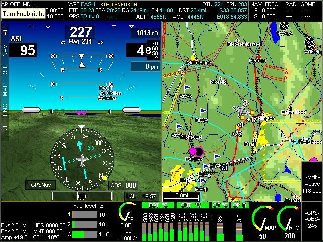
24 Screen 5 Large moving map, abbreviated but complete primary flight instruments on right, small engine monitor strip below. This is screen 5 with the large moving map. In this case we used the map menu (F4 button on the left) to switch both terrain background as well as VMAP items off (roads, towns etc). We also switched the map to Track up. Note that the aircraft symbol moved lower and now points up. The map rotates around the aircraft depending on the current ground track. This mode of map operation lends itself to navigation tasks by removing clutter not related to aeronautical navigation. Screens 6,7 and 8 These screens are repeats of screens 1, 2 and 5 but without the engine monitor. These screens are suitable for applications where you have no engine monitoring system connected or the task of engine monitoring is dedicated to a second EFIS. In these cases, consider selecting one of these as the default startup screen. You do this in the Operations setup menu and this is found, like most setups, in the System setup menu.


25 Screen 9 Plates viewer tool. Similar in looks to screen 5 but instead of map uses plates viewer. This screen when active uses button F7 (on left) as plates selection tool. Plate files compiled with the MGL Plates compiler are placed and used directly from an SD card. Operating the plates system is quite simple: Plates are grouped by airport and the plates compiler produces a single file containing all the plates for a single airport. Using the F7 key we are presented with: Choosing Select from Airport plates shows all the airport plate files on the SD card, choose the airport, then you get presented with a list of plates for that airport. Simply choose the plate you would like to view. If the plate is geo-referenced, the aircraft symbol will be drawn on the plate in the correct heading and location. The most recently used plates can be quickly accessed using the Select from recent plates function. You can also create a more permanent favourite plates selection using
26 the plates viewer from menu level 2. Should you want to create your own plates, it's quite simple. Use the free plate compiler that is available for your EFIS from This handy tool can be used to import pdf files and group them into plate files for your EFIS. You can import not just pdf files but also image files. You may have noticed info plates. This is a special category of plates where you would place information not related to airports, perhaps notes or general procedures or anything you like. Most aviation authorities that make plates available provide them in the popular pdf format for use with Adobe's PDF viewer.
27 Basic navigation with the G2 The G2 EFIS can provide many navigation sources. These are individually enabled in the system setup. GPS Navigation sources GPS navigation to a fix: This is the most common type of navigation used on a G2 system. It requires an internal or external GPS system that is receiving a valid fix. You navigate to a fix such as a waypoint using navigation aids such as HITS (Highway in the sky) or a HSI (Horizontal situation indicator) with a CDI (Course deviation indicator). This type of navigation is used with GPS direct to as well as route (Flightplan) navigation where you would follow a string of waypoints. Waypoints come in a large variety of types. From simple waypoints that are just some particular undefined location to airports and navigation aids such as VOR and NDB stations. In all cases this type of navigation involves a destination point that you want to get to and a track that you need to follow to get there. GVOR navigation VOR works on the principle of identifying a course to or from a VOR station. This is called a radial. You can follow a radial to or from a VOR station or use the radial to intercept other navigation aids such as another VOR station. GVOR is a GPS based simulation of a VOR system. This does not require an existing navigation receiver connected to your EFIS but rather uses knowledge of the actual locations of the real VOR stations to simulate these. GVOR navigation on the G2 system emulates real VOR navigation very closely. GLS approaches GLS approaches are similar to ILS approaches except that you use a GPS as navigation source. This kind of approach uses knowledge of a runways exact location, orientation and elevation to simulate a localizer approach with a glide slope. External navigation sources You can connect several types of external navigation sources. The simplest of these is an analog navigation source. These types of sources would normally provide a +/-150mV signal to drive a needle in a navigation instrument. The EFIS can use these signals to display a CDI and a glide slope. This means it can be used to connect to an external VOR, ILS or glide slope receiver. Three ARINC 429 inputs are available and a large variety of navigation sources can be connected here. One popular navigation source would be a Garmin 430W which will provide a certified GPS, VOR, ILS and glide slope. If you are interested in a G430W, please view the corresponding manual on how to connect and configure both the G430W as well as the EFIS. You can find this manual on the MGL Avionics website
28 Using the GPS to navigate to a waypoint This type of navigation is perhaps the most common and also the most easy to use. Your system can have waypoint information available from three active sources at the same time. These sources are: The primary navidata file This is your main aeronautical navigation database. It contains just about everything you need: Waypoints, navaids, airports, airspace data, obstacle data and more. You can have up to 26 of these files installed in your system but only one is active at any one time. You select the currently active navidata file using the NAV button on the left keypad. Most users will only be using one primary navidata file. The secondary navidata file You can install a secondary navidata file that will be active at the same time as the primary navidata file. This is useful if you are using a subscription product as your primary navigation database (for example Jeppesen navdata). You might want to maintain your own navidata database which indeed, you can do using a free Windows application called MGL Central, a nifty flight planning and aviation database tool. This way you can use both a subscription product and your private database all at the same time. The G2 EFIS only uses waypoints (including navaids) and airport information from a secondary file. Airspaces and other items are always used from the primary database. The supplementary waypoint file This file is always present on your EFIS even if it is empty. Using the Supplementary waypoint editor on your EFIS you can create any type of waypoint on the fly right inside your EFIS. Please view the document MGL EFIS Files from the MGL Avionics website at for more detailed information on the various navidata files and region codes.
![Selecting a waypoint for direct to navigation using the GPS. Press the [SHIFT] button and then press the [1] button (notice the word goto above the button).](/docs-images/72/67645433/images/29-0.jpg "You will see a window like the following: Use the LOG key to activate a filter that will allow you to select the type of waypoints to want to consider.")
29 Selecting a waypoint for direct to navigation using the GPS. Press the [SHIFT] button and then press the [1] button (notice the word goto above the button). You will see a window like the following: Use the LOG key to activate a filter that will allow you to select the type of waypoints to want to consider. You can select items like waypoints, airports, navaids and so on. All items will appear in order of distance from your current position and you can page right through all available waypoints but if you need to find a waypoint that is far away, it is much easier to use the search function (press [ENTER] to open the search function. You can search short or long waypoint names. In the search function you enter characters much like you do using a mobile phone using the numeric keypad. Let's have a look at the information shown: Each waypoint starts with a single letter: W, N, or S. This is just for your information and tells you where this waypoint comes from: Supplementary waypoint file, primary navidata or secondary navidata. This is followed by the waypoints short identifier. This can be up to 6 characters long. This is then followed by the long, descriptive file name and finally the distance from your current position to that waypoint. Want to go somewhere? Just select the waypoint using the numeric keypad.

30 For this example we chose to fly to Battle Mountain. Now the GPS information bar at the top of the display shows some interesting information: Also, in the following picture we captured no less than three navigation aids telling us what to do: The purple wings are banking slightly to the right. This is the Flight Director often referred to as FD. That means we are not pointing in quite the right direction. The HSI tells us the same story we need to turn right a bit but we are pretty much on track. This agrees with the alignment of the green boxes, the Highway in the sky. As a side note, if those boxes would show in red, it means we are going the wrong way... Need to go to a new waypoint, just select it. Want to deselect a waypoint? If a waypoint is active you will find a function on Menu level 1 to deactivate it. Route/Flightplan navigation Route and flightplan navigation and creating flightplans on the EFIS is covered in a separate manual. Have a look at the Flightplan menu as well as the Interactive map and flightplan tool.
31 Finally... Of course, this guide has only touched on the more important parts of the G2 EFIS system. There is much more. In an effort to make the manual more handy, the total documentation is split into smaller units with the aim of not making any of these longer than pages maximum. These documents are live. They get updated and new documents will appear. Some are written by MGL Avionics and some are even written by users of the systems. Please have a look at the EFIS manuals section at for more documents as they become available. These documents typically concentrate on a subject or group of related subjects.
IEFIS alteration guide
 IEFIS alteration guide This document details how to modify existing screens or create new ones using the iefis screen designer. This guide is applicable for the following products: iefis Discovery iefis
MGL Avionics. Odyssey and Voyager G1 and G2. Interactive Map and Flightplan tool
 MGL Avionics Odyssey and Voyager G1 and G2 Interactive Map and Flightplan tool Table of Contents Introduction...3 Opening the IMFT...4 The IMFT in Waypoint mode...5 The IMFT in Goto mode...6 The IMFT in
FriendlyPanels
 FriendlyPanels Software WARNING This operating manual has been writen following the original GARMIN GNS 430/430A Pilot s Guide and Reference, but it's not intended to be valid for training purposes other
This document keeps track of firmware revisions for the MGL Avionics Stratomaster XTreme instrument range.
 XTreme Firmware revisions Document - English 1.14 Introduction This document keeps track of firmware revisions for the MGL Avionics Stratomaster XTreme instrument range. The XTreme's firmware can be upgraded
IEFIS panel installation manual
 IEFIS panel installation manual This document details hardware installation and system configuration of an iefis panel. This document is applicable for the following iefis panels and ibox devices: IEFIS
AFMS, Garmin G5 AML STC Rev. 3 Page 2 of 10
 LOG OF REVISIONS Rev Page Description Date of Approval FAA Approval 1 All Original Issue 7/22/2016 Robert Murray ODA STC Unit Administrator 2 All Added information regarding G5 DG/HSI 4/28/2017 Robert
IEFIS panel installation manual
 IEFIS panel installation manual This document details hardware installation and system configuration of an iefis panel. This document is applicable for the following iefis panels and ibox devices: IEFIS
GPS 500. Quick Reference
 GPS 500 Quick Reference 1 KeyS AND KNOBS Left and Right-hand Keys and Knobs l The Power Knob controls unit power. Rotate clockwise to turn the unit on. RNG The range key allows you to select the desired
PCEFIS VERSION 3.6 SOFTWARE SUMMARY DESCRIPTION Sellers Aviation Inc
 PCEFIS VERSION 3.6 SOFTWARE SUMMARY DESCRIPTION WWW.PCFLIGHTSYSTEMS.COM Sellers Aviation Inc. 352-804-7217 PCFLIGHTSYSTEMS PCEFIS VERSION 3.6 SOFTWARE DISPLAY SUMMARY Bearing to destination* Heading (slaved
Range (map scale) Menu. COM power/volume. COM flip-flop. Direct-To. Enter. VLOC flip-flop. VLOC volume. Clear. Small right knob.
 Menu. COM power/volume. COM flip-flop. Direct-To. Enter. VLOC flip-flop. VLOC volume. Clear. Small right knob.") GNS 430 Quick Reference KEYS AND KNOBS Left-hand Keys and Knobs Right-hand Keys and Knobs COM power/volume VLOC volume COM flip-flop VLOC flip-flop Range (map scale) Direct-To Clear Menu Enter Small left
GNS 430 Quick Reference KEYS AND KNOBS Left-hand Keys and Knobs Right-hand Keys and Knobs COM power/volume VLOC volume COM flip-flop VLOC flip-flop Range (map scale) Direct-To Clear Menu Enter Small left
Operation of DynaFlight-SeisBag And Simulator
 THIS MANUAL CONTAINS INSTRUCTIONS FOR: Operation of DynaFlight-SeisBag And Simulator DynaNav Systems Inc. 121 18799 Airport Way Pitt Meadows. BC, Canada, V3Y 2B4 www.dynanav.com DynaFlight-SeisBag Deployment
GRT Vision Addendum to the GRT Remote App User Manual 08/19/2015
 GRT Vision Addendum to the GRT Remote App User Manual 08/19/2015 Also refer to the GRT Remote App User Manual available at: http://www.grtavionics.com/grt%20remote%20app.pdf GRT AVIONICS, INC. 1 GRT VISION
SeeYou Mobile Tips. Paul Remde September 1, Preliminary Not complete or corrected yet
 SeeYou Mobile Tips Paul Remde www.cumulus-soaring.com paul@remde.us September 1, 2011 Preliminary Not complete or corrected yet SeeYou Mobile is powerful and yet easy-to-use (once setup to your liking)
EFIS App for ipad Operation Manual. Table of Contents. II. The Standby Mechanical Gauges. 4. Tech Support... 16
 1 EFIS App for ipad Operation Manual II. The Standby Mechanical Gauges 4. Tech Support... 16 Table of Contents 1. Introduction to EFIS App for ipad... 3 2. Configuring the Device and Host... 4 I. Configuring
GNS 430/430A. Quick Reference
 GNS 430/430A Quick Reference KEYS AND KNOBS 1 2 3 4 5 6 7 8 9 10 11 12 13 14 15 16 17 18 1 COM Power/Volume 7 RNG (map range) 13 OBS 2 VLOC Volume 8 MENU 14 MSG (message) 3 COM Flip-flop 9 ENT (enter)
MGL Avionics. iefis. Plates from PocketFMS. User manual. Manual dated 12 December Page 1
 MGL Avionics iefis Plates from PocketFMS User manual Manual dated 12 December 2017 Page 1 Table of Contents General...3 About plates...3 Example approach plate...4 Plates and the iefis...5 The plate viewer...6
The GF-2 is able to measure G-forces even if the instrument is not mounted exactly on the vertical axis of the aircraft.
 GF-2 +-10g Tilt Compensated dual range aviation G-force meter Operating Manual English 1.00 Introduction The GF-2 is a 3 1/8 G-force meter capable of measuring G-forces exerted in an aircraft up to +-10g.
Installation Manual. Caution: Preliminary. Due to software development occurring at this time, this manual may contain inaccuracies and omissions.
 Installation Manual Caution: Preliminary Due to software development occurring at this time, this manual may contain inaccuracies and omissions. Manual Version: Preliminary Date: 10/18/04 Grand Rapids
model: 660 Quick Start Manual
 model: 660 Quick Start Manual Copyright 2016 Garmin Ltd. or its subsidiaries. All rights reserved. This manual reflects the operation of System Software version 1.0 or later. Some differences in operation
GNS 430/430A. Quick Reference
 GNS 430/430A Quick Reference KEYS AND KNOBS 1 2 3 4 5 6 7 8 9 10 11 12 13 14 15 16 17 18 1 COM Power/Volume 7 RNG (map range) 13 OBS 2 VLOC Volume 8 MENU 14 MSG (message) 3 COM Flip-flop 9 ENT (enter)
1.- Introduction Pages Description 19.- Tutorial 20.- Technical support
 FriendlyPanels Software WARNING This operating manual has been written to be used only with Microsoft Simulator. FriendlyPanels www.friendlypanels.net fpanels@friendlypanels.net Flight Table of Contents
model: 660 Quick Start Manual
 model: 660 Quick Start Manual Copyright 2016-2018 Garmin Ltd. or its subsidiaries. All rights reserved. This manual reflects the operation of System Software version 3.3 or later. Some differences in
USER S MANUAL Solo Flight Panel. User s Manual. Rev 1.6 October VirtualFly, S.L. tel
 User s Manual Rev 1.6 October 2015 1 TABLE OF CONTENTS 1. IDENTIFICATION OF ELEMENTS 2. INSTALLATION 3. START UP 4. SELECTION OF PANEL TYPE (according to plane) 5. ANALOGIC PANEL INDICATORS 6. RADIOSTACK
GPSMAP 695/696. Portable Aviation Receiver Quick Reference Guide
 GPSMAP 695/696 Portable Aviation Receiver Quick Reference Guide Overview Overview 7 WVGA (800x480) Color Display Power Button Backlit Keypad Unit Overview 1 SD Card Slot External GPS Antenna Connector
The TP-3 can display any combination of 1 to 4 analog channels in a horizontal / vertical bargraph or a numeric display format.
 Vega TP-3 4 Channel Universal Analog input (Pressure / Temperature / Current / Volts) indicator Operating Manual English 1.00 Introduction The TP-3 is a 2 1/4 sunlight readable 4 channel universal analog
EFIS Horizon Cable Description
 EFIS Horizon Cable Description Dual Display Unit EFIS System Dual AHRS/Air Data Computer March 1, 2004 Rev A Grand Rapids Technologies, Inc. Revision History Rev A - 3/1/04 Initial Release Overview This
Flight Computer 1.0. Users Guide.
 Flight Computer 1.0 Users Guide. Torrent d en Puig, 31. 08358, Arenys de Munt, Barcelona,Catalonia,Spain E-mail: sales@xicoy.com. Fax: +34 933 969 743 web: www.xicoy.com Xicoy WEEE register number: ES004749
Aeronautical Navigator USER MANUAL. Your Journey, Our Technology
 Aeronautical Navigator USER MANUAL Your Journey, Our Technology INDEX Navigatore Aeronautico AvMap EKPV 1. LEARN BEFORE USE 4 I. Safe temperature range 4 II. Battery and power source recommendations 4
AFMS, Garmin G5 AML STC Rev. 1 FAA APPROVED Page 2 of 7
 LOG OF REVISIONS Date of Rev Page Description FAA Approval Approval 1 All Original Issue See Cover See Cover FAA APPROVED Page 2 of 7 TABLE OF CONTENTS SECTION 1. GENERAL... 4 SECTION 2. LIMITATIONS...
AVSIM Commercial FSX Utility Review. GeoApr. Product Information
 AVSIM Commercial FSX Utility Review GeoApr Publishers: Flight 1 Product Information Description: Geo-Reference Approach Plates for FSX. Download Size: 9.62 MB Format: Download Simulation Type: FSX Reviewed
GPS Tutorial for Hikers How to efficiently use your mobile as GPS navigator for hiking
 GPS Tutorial for Hikers How to efficiently use your mobile as GPS navigator for hiking By Marc TORBEY Examples from the Android software OruxMaps V1.0 1 Table of contents Basics about GPS for hiking slide
Boating Tip #45: Chartplotters
 Boating Tip #45: Chartplotters As navigation technology has advanced, hand held GPS receivers have further evolved into chartplotters. Chartplotters graphically display a vessel s position, heading and
USER S MANUAL SOLO PRO. User s Manual. Rev 1.1 June VirtualFly, S.L. tel
 User s Manual Rev 1.1 June 2016 1 TABLE OF CONTENTS 1. IDENTIFICATION OF ELEMENTS 2. INSTALLATION 3. START UP 4. SELECTION OF PANEL TYPE (according to plane) 5. ANALOGIC PANEL INDICATORS 6. RADIOSTACK
FILSER ELECTRONIC GmbH LXFAI, data-fil, conv-fil, vali-fil programs for PC s, LXFAI data-fil, conv-fil, vali-fil programs for PC s VERSION 2.
 FILSER ELECTRONIC GmbH LXFAI, data-fil, conv-fil, vali-fil programs for PC s, 1997 LXFAI data-fil, conv-fil, vali-fil programs for PC s VERSION 2.4 F I L S E R E L E C T R O N I C G m b H LXFAI, data-fil,
AT01 AIRPLANE FLIGHT MANUAL
 1.0 General The airplane is equipped with a Bendix / King KMD 150 Multifunction Display / GPS Navigator herein referred as the Navigator. The KMD 150 is capable of providing VFR (IFR) enroute and terminal
Navigational Aids 1 st Semester/2007/TF 7:30 PM -9:00 PM
 Glossary of Navigation Terms accelerometer. A device that senses inertial reaction to measure linear or angular acceleration. In its simplest form, it consists of a case-mounted spring and mass arrangement
I CALCULATIONS WITHIN AN ATTRIBUTE TABLE
 Geology & Geophysics REU GPS/GIS 1-day workshop handout #4: Working with data in ArcGIS You will create a raster DEM by interpolating contour data, create a shaded relief image, and pull data out of the
Vega TC-4. Introduction. 1 Features. Four channel thermocouple (EGT/CHT) indicator. Operating Manual English 1.04
 indicator. Operating Manual English 1.04") Vega TC-4 Four channel thermocouple (EGT/CHT) indicator Operating Manual English 1.04 Introduction The TC-4 is a 2 1/4 (57mm) sunlight readable 4 channel thermocouple color display instrument. The TC-4
Vega TC-4 Four channel thermocouple (EGT/CHT) indicator Operating Manual English 1.04 Introduction The TC-4 is a 2 1/4 (57mm) sunlight readable 4 channel thermocouple color display instrument. The TC-4
Stream Map USA Manual
 1. INTRODUCTION When Stream Map USA is launched, a map of North America opens showing your current location and a colored area highlighting the states covered. Stream Map USA Manual This manual is designed
G1000TM. system overview for the Diamond DA40
 G1000TM system overview for the Diamond DA40 Record of Revisions Revision Date of Revision Revision Page Range Description A 02/14/05 2-1 2-15 Initial release. Garmin G1000 System Overview for the DA40
USER S MANUAL Duo Flight Panel. User s Manual. Rev 1.0 June VirtualFly, S.L. tel
 User s Manual Rev 1.0 June 2015 1 TABLE OF CONTENTS 1. IDENTIFICATION OF ELEMENTS 2. INSTALLATION 3. START UP 4. SELECTION OF PANEL TYPE (according to plane) 5. ANALOGIC PANEL INDICATORS 6. RADIOSTACK
Reliable technology for reliable reference.
 SOLID-STATE SYSTEMS VERTICAL REFERENCE SYSTEM - VRS-3000 Go with the system that won t lose momentum. Reliable technology for reliable reference. Accurate flight cues are everything to a pilot. Your flight
EFIS Horizon Display Unit Connector Definitions
 EFIS Horizon Display Unit Connector Definitions June 7,2004 Rev D Grand Rapids Technologies, Inc. Revision History Rev C - Changed naming convention to +Left/+Right and +Up/+Down for loc/gs inputs. No
10.4 HXr EFIS. GRT Avionics. (616) fax (616) above, beyond.
 fax (616) above, beyond.") Grand Rapids Technologies, Inc. 10.4 HXr EFIS The large screen EFIS for your experimental airplane. Insets...Preserving the View One look at the HXr and you sense the situational awareness provided by
Grand Rapids Technologies, Inc. 10.4 HXr EFIS The large screen EFIS for your experimental airplane. Insets...Preserving the View One look at the HXr and you sense the situational awareness provided by
Airtalk I/O Extender
 Airtalk I/O Extender for Stratomaster Enigma, Odyssey and Voyager EFIS systems User manual Document date 21/6/2007 General The I/O Extender is a small unit designed to extend the I/O interface capabilities
AVIONICS FUNDAMENTALS MAINTENANCE TRAINING /27/2006 Chapter 5 - Inertial Reference
 Gyros Inside Indicators Figures 5-4 and 5-5 illustrate how gyros can be used inside indicators mounted directly on the flight instrument panel. Figure 5-4 shows a gyro mounted with its spin axis vertical.
FltPlan Go FAQ. What operating system is FltPlan Go available for? FltPlan Go is available on ios (ipad/iphone), Android, Windows 10, and Mac.
, Android, Windows 10, and Mac.") What operating system is FltPlan Go available for? FltPlan Go is available on ios (ipad/iphone), Android, Windows 10, and Mac. How much does FltPlan Go cost/how many devices can you download it on? FltPlan
What operating system is FltPlan Go available for? FltPlan Go is available on ios (ipad/iphone), Android, Windows 10, and Mac. How much does FltPlan Go cost/how many devices can you download it on? FltPlan
An object in 3D space
 An object in 3D space An object's viewpoint Every Alice object has a viewpoint. The viewpoint of an object is determined by: The position of the object in 3D space. The orientation of the object relative
Vulcan. Getting Started ENGLISH. bandg.com
 Vulcan Getting Started ENGLISH bandg.com Vulcan Getting Started 3 4 Vulcan Getting Started Contents 9 Introduction 9 The Home page 10 Application pages 11 Integration of 3 rd party devices 12 GoFree wireless
These instructions will help guide you through uploading the BMW Safari GPS routes file to your GPS device.
 BMW Safari GPS route file installation instructions These instructions will help guide you through uploading the BMW Safari GPS routes file to your GPS device. The file type used for the BMW Safari routes
TEST EXAM PART 2 INTERMEDIATE LAND NAVIGATION
 NAME DATE TEST EXAM PART 2 INTERMEDIATE LAND NAVIGATION 1. Knowing these four basic skills, it is impossible to be totally lost; what are they? a. Track Present Location / Determine Distance / Sense of
simplugins Panel Builder
 simplugins Panel Builder ADD-ON MFD GPS BajuSoftware, LLC Page 1 of 38 Version 1.4 April, 2015 Table of Contents Introduction... 3 Technical Requirements... 5 Installation Procedure... 6 Running the GPS
Blaze ASI-5. Introduction. 1 Features. Airspeed Indicator (ASI) Operating Manual English 1.00
 Operating Manual English 1.00") Blaze ASI-5 Airspeed Indicator (ASI) Operating Manual English 1.00 Introduction The ASI-5 is a 3 1/8 sunlight readable instrument that provides a wide range airspeed indication in both digital and analog
Blaze ASI-5 Airspeed Indicator (ASI) Operating Manual English 1.00 Introduction The ASI-5 is a 3 1/8 sunlight readable instrument that provides a wide range airspeed indication in both digital and analog
FSFlyingSchool2010 Voice Command Pack
 FSFlyingSchool2010 Voice Command Pack Manual Web: www.fsflyingschool.com Support: [www.fsflyingschool.com/forum] Forum: [www.fsflyingschool.com/forum] Sales: [sales@fsflyingschool.com] Published: June
SOLID-STATE SYSTEMS VRS / ESIS / EHSI
 SOLID-STATE SYSTEMS VRS / ESIS / EHSI VERTICAL REFERENCE SYSTEMS - VRS-3000 & 4000 Go with the system that won t lose momentum Reliable technology for reliable reference. Accurate flight cues are everything
MINIMUM EQUIPMENT LIST REGISTRATION: SERIAL #:
 23 COMMUNICATIONS 23-1 -05-1 Radio Management Unit (RMU) (Honeywell Equipped Aircraft Only) -10-1 Communications System (VHF & UHF) -10-2 High Frequency (HF) Communication System C 2 1 (O) One may be inoperative
Appendix E: Software
 Appendix E: Software Video Analysis of Motion Analyzing pictures (movies or videos) is a powerful tool for understanding how objects move. Like most forms of data, video is most easily analyzed using a
Version 9 User Guide for. Developed for Omnitracs
 Version 9 User Guide for Developed for Omnitracs Table of Contents Welcome to CoPilot Truck 4 Driving Screen 4 Driving Menu 5 GO TO MENU: Single Destination Navigation 6 Address 6 My Places 7 Points of
Moomba Boats PV480 Color Display
 Moomba Boats PV480 Color Display 2018 Owner s Manual 1715055 2017-08-30 We continually strive to bring you the highest quality, full-featured products. As a result, you may find that your actual display
AG-NAV GUÍA LITE Differential GPS Guidance System. OPERATOR S HANDBOOK Version Sept. 2017
 AG-NAV GUÍA LITE Differential GPS Guidance System OPERATOR S HANDBOOK Version 1.1.5 Sept. 2017 INFORMATION AG-NAV INC. 30 Churchill Drive Barrie, Ontario L4N 8Z5 CANADA TOLL FREE: (800) 99-AGNAV TELEPHONE:
3. Map Overlay and Digitizing
 3. Map Overlay and Digitizing 3.1 Opening Map Files NavviewW/SprayView supports digital map files in ShapeFile format from ArcView, DXF format from AutoCAD, MRK format from AG-NAV, Bitmap and JPEG formats
Vega ASI-4. Introduction. 1 Features. Airspeed Indicator (ASI) Operating Manual English 1.00
 Operating Manual English 1.00") Vega ASI-4 Airspeed Indicator (ASI) Operating Manual English 1.00 Introduction The ASI-4 is a 2 1/4 sunlight readable instrument that provides a wide range airspeed indication in both digital and analog
Vega ASI-4 Airspeed Indicator (ASI) Operating Manual English 1.00 Introduction The ASI-4 is a 2 1/4 sunlight readable instrument that provides a wide range airspeed indication in both digital and analog
2 MOVING MAP. Set Up Moving Map Display. Set the Chart Theme
 2 MOVING MAP The Moving Map provides you with position information when connected to an approved GPS receiver. Set Up Moving Map Display To meet your needs, FliteMap provides numerous options for setting
SG102 AHRS Installation/Calibration Utility
 SG102 AHRS Installation/Calibration Utility User Guide Rev G, 09/30/2014 82011-ICUG Rev G [This page intentionally left blank] 82011-ICUG Rev G SG102 AHRS Installation/Calibration Utility 1 1 TABLE OF
Aeronautical Navigator USER MANUAL. Update Software version V R. Your Journey, Our Technology
 Aeronautical Navigator USER MANUAL Update Software version V1.6.069R Your Journey, Our Technology INDEX Navigatore Aeronautico AvMap EKPV 1. LEARN BEFORE USE 4 I. Safe temperature range 4 II. Battery
GO XSE. Getting Started. simrad-yachting.com ENGLISH
 GO XSE Getting Started ENGLISH simrad-yachting.com Contents 7 Introduction 7 The Home page 8 Application pages 10 Basic operation 10 System Controls dialog 10 Turning the system on and off 11 Selecting
EFIS Horizon Cable Description
 EFIS Horizon Cable Description Single Display Unit Jan 23, 2004 Rev C Grand Rapids Technologies, Inc. Revision History 12/15/03 Initial Release Rev B - General Updates Rev C - 1/23/04 - Changed Red/White
Wrist GPS Training Device GH-625XT Quick Start Guide
 Wrist GPS Training Device GH-625XT Quick Start Guide Version 3.0 Power / Light Up Page Down Esc/Lap Enter This version is usage for Firmware Version 2.02 or above http://www.gs-sport.com What is GPS? GPS
Push. Figure A4.1 Push.
 Push Figure A4.1 Push. Push is a hardware controller designed by Ableton and Akai to drive Live s Session View. Simply connect the Push unit using the provided USB cable to your computer and off you go.
CHAPTER 34 - NAVIGATION AND PITOT-STATIC SYSTEMS TABLE OF CONTENTS
 NAVIGATION AND PITOT-STATIC SYSTEMS 34-00 General 1 FLIGHT ENVIRONMENTAL SYSTEMS 34-10 Pitot-Static - Serials w/o Perspective Avionics 1 Pitot-Static - Serials w/ Perspective Avionics 1 Outside Air Temperature
2 SELECTING AND ALIGNING
 2 SELECTING AND ALIGNING Lesson overview In this lesson, you ll learn how to do the following: Differentiate between the various selection tools and employ different selection techniques. Recognize Smart
INSPIRE 1 Quick Start Guide V1.0
 INSPIRE Quick Start Guide V.0 The Inspire is a professional aerial filmmaking and photography platform that is ready to fly right out of the box. Featuring an onboard camera equipped with a 0mm lens and
ODES Zeus Touch Owner s Manual
 ODES Zeus Touch 2017 Owner s Manual 2016-09-15 1611997 We continually strive to bring you the highest quality, full-featured products. As a result, you may find that your actual display screens may be
Rotated earth or when your fantasy world goes up side down
 Rotated earth or when your fantasy world goes up side down A couple of weeks ago there was a discussion started if Fractal Terrain 3 (FT3) can rotate our earth. http://forum.profantasy.com/comments.php?discussionid=4709&page=1
G1000 Integrated Flight Deck. Cockpit Reference Guide for the Quest Kodiak 100
 G1000 Integrated Deck Cockpit Reference Guide for the Quest Kodiak 100 Instruments Engine indication system Transponder/Audio Panel GPS Navigation Planning Procedures Operation Annunciations & Alerts
Single Screen or Split Screen. 2D and 3D
 SkyPad 3 Details Seattle Avionics offers a powerful Windows 7 tablet, called the SkyPad 3, that incorporates everything we've learned in nine years of making aviation safer, easier, and more affordable.
Phantom 2 Reference Guide
 Phantom 2 Reference Guide Contents Section 1: Operation and Preparing for Flight. 2 Transmitter introduction 2 Controlling the Drone 2 Turning on the Transmitter 3 Range Extender 3 Basic Drone Parts 4
AF-3400s, AF-3500s, AF-4500s
 AF-3400s, AF-3500s, AF-4500s EFIS System - Engine Monitoring System Moving Map Patents 6,271,769 B1 and 6,940,425 User Guide and Installation Manual Version 7.4 03/12/2012 IMPORTANT PRE-INSTALLATION NOTICE
Navigating the User Interface
 Navigating the User Interface CHAPTER 1 If you re new to the AutoCAD Civil 3D software environment, then your first experience has probably been a lot like staring at the instrument panel of an airplane.
Arduino IDE Friday, 26 October 2018
 Arduino IDE Friday, 26 October 2018 12:38 PM Looking Under The Hood Of The Arduino IDE FIND THE ARDUINO IDE DOWNLOAD First, jump on the internet with your favorite browser, and navigate to www.arduino.cc.
How to use Leica DISTO X310
 How to use Leica DISTO X310 Switch On and Off The red Dist on key displayed here switches on the instrument and the laser in a single press. Pressing the Clear off button for 2 seconds switches the instrument
G3X. Multi Function Display Quick Reference Guide
 G3X Multi Function Display Quick Reference Guide Overview GPS Navigation Flight Planning Hazard Avoidance Additional Features Appendices Index Warnings, Cautions & Notes WARNING: The indicators represented
ATNS. USING Google EARTH. Version 1
 ATNS USING Google EARTH Version 1 ATNS/HO/Using Google Earth Page 1 25/04/2013 CONTENTS 1. BASIC SETUP 2. NAVIGATING IN GOOGLE EARTH 3. ADDING OBJECTS TO GOOGLE EARTH 4. USER HELP REFERENCES ATNS/HO/Using
STRATUS HORIZON PRO Pilot s Guide
 Getting Started STRATUS HORIZON PRO Pilot s Guide The Stratus Horizon Pro app works with Stratus portable ADS-B receivers to show real-time AHRS (attitude, heading, and reference system) data of your aircraft
Let s Make a Front Panel using FrontCAD
 Let s Make a Front Panel using FrontCAD By Jim Patchell FrontCad is meant to be a simple, easy to use CAD program for creating front panel designs and artwork. It is a free, open source program, with the
Aerobask Skyview. Addendum for v2 ONLY FOR SIMULATION DO NOT USE FOR REAL FLIGHT. Aerobask Syview v2 addendum
 Aerobask Skyview Addendum for v2 ONLY FOR SIMULATION DO NOT USE FOR REAL FLIGHT Page 1/10 Table of Contents INTRODUCTION...3 Before You Fly...3 Targeted audience...3 CUSTOM DATABASE CHANGES...3 CLICK ZONES...4
BRx6 Sensor Calibration Using SurvCE/SurvPC
 OVERVIEW BRx6 Sensor Calibration Using SurvCE/SurvPC The BRx6 internal sensors (tilt, accelerometer and compass) must be calibrated in order to use the electronic bubble and tilted pole corrections in
TopCon X5 Operator's Manual
 TopCon X5 Operator's Manual Part Number TOPCONX5-EN Rev.1.0 Copyright Topcon Precision Agriculture May, 2011 All contents in this manual are copyrighted by Topcon. All rights reserved. The information
CONTOURGPS QUICKSTART GUIDE. Getting to know your Camera. What s In The Box?
 CONTOURGPS + QUICKSTART GUIDE Getting to know your Camera What s In The Box? The ContourGPS camera comes with: Camera 2GB microsd Card 2 Rotating Surface Mount 1 Goggle Mount 1 Li-ion Battery 1 USB Cable
SP-7 AHRS. Firmware upgrade instructions. Installation and calibration
 SP-7 AHRS Firmware upgrade instructions Installation and calibration General This document describes the firmware upgrade procedure and new functionality of the SP-7 Firmware release. The firmware upgrade
In this lab, you will create two maps. One map will show two different projections of the same data.
 Projection Exercise Part 2 of 1.963 Lab for 9/27/04 Introduction In this exercise, you will work with projections, by re-projecting a grid dataset from one projection into another. You will create a map
SkyView Software version 7.0 du
 SkyView Software version 7.0 du 16.9.2013 Version Date Released Changes 7.0 9/16/2013 New: Geo referenced approach / departure procedure charts and airport diagrams. See the Dynon database downloads page
GARMIN s GPS Map 76CSx
 GARMIN s GPS Map 76CSx DESCRIPTION: The GPSMAP 76CSx is a refreshing upgrade of the GPSMAP 76CS, one of our most popular models for outdoor and marine use. This unit features a removable microsd card for
GPS BIKE COMPUTER GB-580. Power / Light / Esc. Up/ Start/ Stop. Down / Lap / Save. Page / Enter GPS BIKE COMPUTER
 Power / Light / Esc Up/ Start/ Stop Page / Enter Down / Lap / Save GPS BIKE COMPUTER 1 What is GPS? GPS stands for Global Positioning System. For 3D fix, we need at least four satellites. Normally the
1 SOFTWARE INSTALLATION
 Welcome to the IVAO Belgium division! This guide is intended to make sure you know your way around the network and get the software ready and connected to accomplish what you are looking for: fly with
This document describes the user interface, navigation and the common resources that are available in SvalSim
 Page 1 Geo2000 SvalSim Documentation This documentation will help you to discover and use the SvalSim geosimulator. It will tell you in general how the simulator works and how to use it. General information
v Overview SMS Tutorials Prerequisites Requirements Time Objectives
 v. 12.2 SMS 12.2 Tutorial Overview Objectives This tutorial describes the major components of the SMS interface and gives a brief introduction to the different SMS modules. Ideally, this tutorial should
Connect each unit to the computer with Paralog running to personalize them for the commpetitors.
 Paralog Performance Competition Judge s Guide Running and judging a wing suit performance competition with Paralog and the Paralog Performance Competition (PPC) web site is not difficult. This document
How to use Leica DISTO D510
 How to use Leica DISTO D510 Switch On and Off The Press key switches and activates the laser in a single press. once quickly to shoot a distance or... Press and hold for 2 seconds to activate continuous
Computer learning Center at Ewing. Course Notes - Using Picasa
 1st January 2014 Computer learning Center at Ewing Course Notes - Using Picasa These course notes describe the content of the Using Picasa course. The course notes are based on Picasa 3. This course material