USB Reader Link R Introduce & Manual
|
|
|
- Jerome Bradley
- 5 years ago
- Views:
Transcription
 USB Reader Link can be set separate setting by user for each machine, one for Brother, one for Fanuc one for Mazak, one for Mitsubishi or etc.")
 USB Reader LinkR DNC or TAPE run 6) USB Reader LinnkR available for Brother Tapping Center all data down/upload to easy for maintenance team 5 Remote switch available USB Reader LinkR unit has the")
 - User friendly interface with 2 line LCD display and 20 key keypad. Keypad symbols can be \"rotated' for full character set.")

1 USB Reader Link R Introduce & Manual USB Reader LinkR Kit easy down/upload data transmission between USB Reader LinkR Kt 1) USB Reader Link can be set 5 remote for 5 controller system 2) USB Reader LinkR Kit 5 remote SETUP are separate setting 3) USB Reader Link can be set separate setting by user for each machine, one for Brother, one for Fanuc one for Mazak, one for Mitsubishi or etc. 4) USB Reader LinkR can be set for data transmission PLC etc. 5) USB Reader LinkR DNC or TAPE run 6) USB Reader LinnkR available for Brother Tapping Center all data down/upload to easy for maintenance team 5 Remote switch available USB Reader LinkR unit has the following feature : - Work with just about any USB flash drive up to 4GB (1 GB include) - Battery opeated (4AA NiMh rechargeable battery include) - Full charged unit can continueusly operate 8+ hour - For permanent hookup use charge only (include) - User friendly interface with 2 line LCD display and 20 key keypad. Keypad symbols can be "rotated' for full character set. - Baud rate values : 300 to 115.2k - Xon/Xoff, CTS/RTS, MZK protocols - Up to 5 user defined and named setups, easily selectable before sending.receiving - Real time clock stamps received files with current date on the USB flash drive - File size and last modified date display before sending - User can also 'peek' into start of the file before sending to see the program number/comment - Drip deef if control is capable via RS232 port - Include : - USB Reader Link - AA NiMh rechargeable batteries (4pcs) - 110vac wall-plug charge - USB 1GB flash memory - RJ45 TO DB25M connector


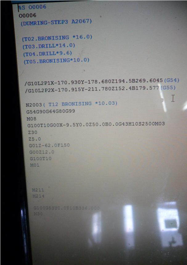

2 - 6 feet cable USB Reader KitR with Brother Tapping Center TC-S2A, A00 Control Compareafter download to USB Reader KitR and open file
3 USB Reader Link R Introduce & Manual USB Reader Link Quick Start Guide 1) There is a User Manual in PDF format on the enclosed USB memory stick - please, read that first. 2) Insert a USB memory stick into the USB Reader Link unit. Remove the small pink plastic stop from the USB Reader Link unit On/Off switch and turn the unit on. 3) After a couple of seconds the USB Reader Link will di splay its main menu. Press 4 for SETUP. Follow the instructions in the User Manual to set and name the first machine. Hint: make sure to match the machine s baud rate. For 90% of the controls ISO code, LF only and XON/XOFF handshake will work fine. At the end press the ENT key to get back to the Main Menu. 4) Select 2 for a Machine to USB transfer. Select the single dot, press ENT and name the incoming file for simplicity 123 and press ENT (read the User Manual how to rotate for letters) at the end press ENT again. The USB Reader Link unit is now ready to receive a file. Now perform a Send or Punch operation at the machine tool. As the G code program is being sent, the second line of the USB Reader Link unit s LCD display shows the incoming lines. Once the transfer ends, the LCD display will show the last received characters (LF signals line feed and CR signals carriage return characters.). Press ESC key to display the name and number of characters of the just received program then press ESC again. 5) Now at the CNC control rename the just punched program and set the control to receive. Once ready, on the USB Reader Link unit at the Main Menu select ite m 1), arrow down to the just received 123 program and press ENT key. The second line of the LCD display will show the outgoing lines. Once done your CNC control should have and display the just received program. You can also take program 123 on the USB memory stick to your computer and view/edit it for example with Notepad. 6) Based on this experience now you can set up the rest of the machines. The similar machines can use the same setup of the USB Reader Link unit. You can name a setup in the unit (Brother, FANUC, MAZAK, etc ) up to 8 characters long. Before sending/receiving while at the Main Menu you can select a different setup using the LIST and the arrow keys. 7) The USB Reader Link can also drip feed a CNC control if the control itself is capable of doing that. For that application an USB Reader Link per machine is recommended with a permanent hookup. For a permanent hookup you may remove the 4 AA batteries and connect the USB Reader Link to its charger all the time. While in the SETUP menu normally the setup is for viewing only. To enable the change of BAUD rate, etc.. you need to type in - while in the SETUP menu - the numbers 147 blindly. This code unlocks the view only mode. Once you leave the SETUP menu and re-enter it you need t This is to prevent accidental parameter change. If the rechargeable battery is completely depleted, the LCD screen will show nothing after turning the unit on. In such a case: 1) Turn the unit OFF. 2) Connect the charger for about 5 minutes. 3) Turn the unit ON - display should come back and the red charge light should turn on. Charge the unit like that before using it for at least 10 minutes - after done using it connect the charger back having the unit ON but the USB key removed until fully charged.
4 Communicating with a G-code control (BROTHER, FANUC, MAZAK, MITSUBISHI or similar) A) From USB memory stick CNC control 1) Plug the USB Reader Link serial cable into the control RS232 port, make sure that the correct USB memory stick is inserted into the unit and turn the unit on. 2) Press the LIST key on the USB Reader Link to make sure that the correct setup is selected - press ENT if the correct setup name is displayed else right/left arrow to the correct name and then press ENT. (You can do a fast parameter check pressing the HOME key instead the LIST, but that shows only while the key is pressed and won t let to change the setup). 3) At the CNC control set the control to receive. Once ready, on the USB Reader Link unit at the Main Menu select item 1), arrow down to the program to be sent and press ENT key. The second line of the LCD display will show the outgoing lines. Once done your CNC control should have and display the just received program. (If there are too many programs on the USB key, you can do a directory search please read the User Manual how to do that). B) From Control to USB memory stick 1) Plug the USB Reader Link serial cable into the control RS232 port, make sure that the correct USB memory stick is inserted into the unit and turn the unit on. 2) Press the LIST key on the USB Reader Link to make sure that the correct setup is selected - press ENT if the correct setup name is displayed else right/left arrow to the correct name and then press ENT. (You can do a fast parameter check pressing the HOME key instead the LIST, but that shows only while the key is pressed and won t let to change the setup). 3) Select 2) for a Machine to USB transfer. Select the single dot, press ENT and name the incoming file (for numbers just press the key, read the User Manual how to rotate for letters). Once the name is done, press ENT again. (You can also key down and press the ENT over an existing program to overwrite it). The USB Reader Link unit is now ready to receive a file. Now perform a Send or Punch operation at the machine tool. As the G code program is being sent, the second line of the USB Reader Link unit s LCD display shows the incoming lines. Once the transfer ends, the LCD display will show the last received characters (LF signals line feed and CR signals carriage return characters.). Press ESC key to display the name and number of characters of the just received program then press ESC again to go back to the Main menu. USB Reader Link can be set 5 remote for 5 controller system USB Reader Link can be set separate setting by user for each machine, one for Brother, one for Fanuc one for Mazak, one for Mitsubishi or etc. Brother Tapping Center USB Reader Link can be set with RS232C connecting of all Brother Tapping Center from older than A00, B00, C00 It very easy for download and upload program from machine to USB and easy for download and upload " All DATA BANK " for maintenance A) From Control to USB memory stick 1) Step 1) Connect RS232C Cable to TC Brother 2) Step 2) DATA BANK => User parameter => Commucation setting (follow recommended sheet) 3) Step 3) On Brother machine select the " Directory diplay " and input program number provised Remark : if program it same number Yes (1) at USB Reader Link R 4) On the USB Reader Link unit at the Main Menu select item 1), arrow down to the program to be sent and press ENT key. The unit will say Sending but nothing else will happen yet. Now at the control go into the CMT menu, press LIST CMT CONTENT followed by START. After few seconds the control will list the available work numbers. Now you can select CMT->NC (LOAD) operation followed by START and the control will read the listed work number(s). Note here, that you can also execute a COMPARE operation using the same steps as for LOAD. 5) After USB Reader LinkR show on screed "Sending" 6) At Brother machine input that program we need to download then EDIT START on panel to press
5 B) From Control to USB memory stick 1) Step 1) Connect RS232C Cable to TC Brother 2) Step 2) DATA BANK => User parameter => Commucation setting (follow recommended sheet) 3) Step 3) On Brother machine select the " Directory diplay " and input program number provised Remark : if program or Parameter it same number Yes (F0) or "Input all remaining" at Brother machine 3) Select 2) for a Machine to USB transfer. Select the single dot, press ENT and name the incoming file (for numbers just press the key, read the User Manual how to rotate for letters). Once the name is done, press ENT again. (You can also key down and press the ENT over an existing program to overwrite it). The USB Reader Link unit is now ready to receive a file. Now go to the CMT menu at the control, INPUT the work number(s), press the NC->CMT (SEND) operation and press START. As the conversational program is sent, the second line of the USB Reader Link unit s LCD display shows the incoming lines. Once the transfer ends, the USB Reader Link unit will display Receiving done message. Press ESC key to display the name and number of characters of the just received program then press ESC again to go back to the Main menu. 4) After USB Reader LinkR show on screed "Receiving" 5) At Brother machine input that program we need to download then EDIT START on panel to press Communicating with a Mazak control/conversational program A) From USB memory stick CNC control 1) Step 1) is same as for FANUC 2) Step 2) is same as for FANUC, just make sure that a setup with MZK code is selected. 3) On the USN Reader Link unit at the Main Menu select item 1), arrow down to the program to be sent and press ENT key. The unit will say Sending but nothing else will happen yet. Now at the control go into the CMT menu, press LIST CMT CONTENT followed by START. After few seconds the control will list the available work numbers. Now you can select CMT->NC (LOAD) operation followed by START and the control will read the listed work number(s). Note here, that you can also execute a COMPARE operation using the same steps as for LOAD. B) From Control to USB memory stick 1) Step 1) is same as for FANUC 2) Step 2) is same as for FANUC, just make sure that a setup with MZK code is selected. 3) Select 2) for a Machine to USB transfer. Select the single dot, press ENT and name the incoming file (for numbers just press the key, read the User Manual how to rotate for letters). Once the name is done, press ENT again. (You can also key down and press the ENT over an existing program to overwrite it). The USB Reader Link unit is now ready to receive a file. Now go to the CMT menu at the control, INPUT the work number(s), press the NC->CMT (SEND) operation and press START. As the conversational program is sent, the second line of the USB Reader Link unit s LCD display shows the incoming lines. Once the transfer ends, the USB Reader Link unit will display Receiving done message. Press ESC key to display the name and number of characters of the just received program then press ESC again to go back to the Main menu.
6 USB Reader Link R Manual The USB Reader Link unit is used to send and receive CNC program files between a CNC control and a USB memory stick. The USB Reader Link unit connects to the CNC control via RS232 port. It can also drip feed the CNC control - providing that the CNC control is capable of receiving and executing a G code program via its RS232 port. The USB Reader Link kit contains the following items: - USB Reader Link unit - 1G USB memory stick (with User Manual installed in PDF format) - Charger with 110VAC wall plug connection - 6 cable with DB25 male connector for CNC connection - 4 NiMh AA battery installed The USB Reader Link unit has an On/Off switch at the top right side, a charger connection with a charge red led on its right side, a USB and an RS232 connector on its top side, a 2x16 character LCD display and a 20 key keypad. Turning the USB Reader Link unit ON and OFF Flip the slide switch on the top right side of the unit to the UP position to turn it ON, and the DOWN position to turn it OFF. After turning the unit ON, its LCD display appears with a serial number, then a Version number, also reporting if the charger is detected or not and finally reporting if it detected a USB memory stick or not. Note here that the USB memory stick is referred to by the CNC LINKS unit as USB key. The unit will also beep few times during the boot procedure. Recommendations to maximize battery life The battery charging is managed by the USB Reader Link units processor. Therefore the unit needs to be turned ON for the charger to operate. If the unit s power switch is turned OFF and the charger is connected, only the so called trickle charge takes place, which is a small charge current and can t really fully charge a battery. The USB Reader Link unit will complain if its battery voltage is getting too low (message on the LED plus beeping once every 2 seconds). That is when the user needs to do the following a) Remove the USB memory stick (if connected) b) Plug in the battery charger c) Turn the unit ON As the unit is charging the small red LED light by the charger connector will be on. Once the charging is done, the light will turn off and the unit will issue a short beeping sound once about every 2 second as a reminder that charging is done and now its time to remove the charger and to turn the unit off. Note here, that if this charging process is interrupted (the user needs to up/down load a program), plugging the charger back will continue the charging process. Also note here, that the user can manually start or stop a charging process in the 5) BATTERY CHECK menu. General keypad operation The USB Reader Link unit has a very user friendly menu system. The user has a 20 key keypad available to make a selection, enter into a menu or type in a filename. The keypad has a few dedicated keys available to speed up certain operations. The rest of the keys are alphanumeric keys to enter numbers and letters. Dedicated keys HOME when listing a directory, pressing the HOME key will take the user to the very beginning of the directory list. Also, pressing the HOME key while at the MAIN menu will show the current BAUD rate, EOB character, code type and handshaking
7 method. END - when listing a directory, pressing the END key will take the user to the very end of the directory list. Also, pressing the END key while at the MAIN menu will show the connection status of the Rx and CTS signals. If the USB Reader link unit is connected to a CNC control, and the CNC control is not sending or receiving, both signals should show OK. LIST - when listing a directory, pressing the LIST key on a file name will toggle between showing the file size/last modified date and showing the first 16 characters of the file on the second line. Pressing the LIST key on a directory name has no effect. Also, pressing the LIST key while at the MAIN menu will show the currently selected SETUP name. At this point the user can press the UP/DOWN or LEFT/RIGHT arrow keys to select a different SETUP name. As the SETUP name is changed, of course the associated BAUD RATE, CODE, EOB and HANDSHAKE method changes as well. Pressing any other key will take the user back to the MAIN menu. This change of SETUP name is in effect as long as the power is ON. After power OFF/ON cycle the default SETUP name will be in effect. ESC normally the ESC key is used to abort an operation and it usually returns to the Main Menu. The ESC key is also used to sow/hide the current date/time while a Main Menu item is displayed. ENT normally the ENT key is used to enter into the selected directory, finish a user entry or initiate the selected operation. ARROW keys - the arrow keys accomplish selection and/or rotation. When the user is asked to type in a program name, any of the number keys can be used. Once a number is typed in, the user can leave it as a number or select a letter, which appears on the same number key by rotating the character with the up or down arrow key. The left arrow serves as a backspace key. The right arrow is used as a selection key is SETUP mode. Navigating the Directory When the USB Reader Link unit is listing the directory of the inserted USB key, the following rules apply: Directory names are shown on the first line. The symbol <DIR> is shown on the second line. File names are shown on the first line. File length and last modified date is shown on the second line. The user can toggle the second line info with the LIST key to show the first 16 characters of the file. Up or Down arrow keys will show the next/previous directory/file name in the current directory. Note here, that the first name in any directory is a single dot. with the <DIR> attribute. If the current directory is a sub-directory, than the second item in the directory list is a double dot.. with the <DIR> attribute. Then the rest of the directory/file names which reside in the current directory follow. If the ENT key is pressed on a Directory name, the user executes an entry into that directory, and a new directory listing appears, and this directory becomes now the current directory. If the ENT key is pressed on a single dot (. <DIR>) normally it has no effect. However if the operation is a MCH - USB key operation, the user is asked to type in the name of the file to be received - see General keypad operation about typing in a name. If the ENT key is pressed on a double dot (.. <DIR>), the user will move up one directory level, the new upper directory will be listed and becomes now the current directory. If the ENT key is pressed on a file name, than the user makes a selection for that file (upload, down load, delete..). Speed search - if the directory list is long, it may take a long time to get to the particular file name just by using the up/down arrow (or END) keys. The user can speed up this file search by start typing in the beginning of the file name using the General
8 keypad operation rules (see above). Once the user typed in a few starting characters, than the user may press the ENT key. A new directory listing will appear for the current directory, with all the file/directory names which will match the just typed in characters. This search is the equivalent of listing a DOS directory using the XYZ*.* format, where XYZ would be the typed characters by the user. Now the user can select the file/directory name from a significantly shorter list with the up/down arrow keys. Note Note here, that for simple directory operation all CNC files can be placed in the root directory this way all directory navigations can be avoided. Also note here that the USB Reader Link unit can read the long file names (longer that 8.3 DOS style), however it will show them in the abbreviated format. Example: SAMPLEPRG.TXT will be shown as SAMPLE~1.TXT (not 8.3 format) PROGRAM1.TXT will be shown as PROGRAM1.TXT (8.3 format) As a file name is displayed the user may press the LIST key which will list the first 16 characters of the file, which may help to identify a file further in case of a long file name. This also may help to determine the exact program number for the CNC control. Some CNC controls are picky about entering the exact program number to be received. When the unit is turned on or a new USB memory stick is inserted, the USB Reader Link unit will show the root directory of the USB stick, (which is also the current directory). Main Menu At the top of the menu system is the Main Menu. The Main Menu is shown by a number (1 through 6), followed by a description. After turning the power on, the USB Reader Links unit will end up at the Main Menu. Also, by pressing the ESC key will normally take the user back to the Main Menu. Always one Main Menu item is shown (on the first line). On the second line the user can toggle with the LIST key showing nothing or the current date/time. The user can navigate the Main Menu items with the up/down arrow key. Pressing the ENT key on the shown item will initiate that operation. Also, the operation can be initiated by pressing the number key associated with the menu item. Example: pressing 3 at the Main Menu will initiate the DELETE operation. The Main Menu of the USB Reader Link unit has the following items: 1) USB key - MCH 2) MCH - USB key 3) DELETE 4) SETUP 5) BATTERY CHECK 6) UPDATE 1) USB key - MCH menu First, the user needs to connect the USB Reader Link unit to the CNC control s RS232 port with the provided cable/connector, and get the CNC control ready to receive. Next the user needs to navigate through the directory system to select the file to be sent to the machine tool (see Navigating the Directory). Once the correct file name is displayed, the user needs to press the ENT key. The USB Reader Link unit now will send the selected file to the CNC control. Sending.. is displayed on the first line, and the content of the file being sent is displayed on the second line. Once sending is finished, the Done sending.. message is displayed. Note here, that this procedure requires that the file to be sent starts normal (usually with a % sign). If it is not the case (upon loading the control will miss the first line), the user has the option to send out a % sign EOB character combination by executing the following procedure: once the proper file name is selected the user should press the LIST key - this will show the beginning of the file. If it looks OK, the user can press the ENT key and the unit will transfer the file as normal. If at the beginning of the file the % sign line appears to be missing, the user can now press the
9 (*%) key (the unit will beep) and then the ENT key - this will transfer % EOB first, then the rest of the file. Note that if the end of file also requires special character, END string may be set - see SETUP menu. 2) MCH - USB key menu First, the user needs to connect the USB Reader Link unit to the CNC control s RS232 port with the provided cable/connector. Next the user needs to navigate through the directory system, and either to select the file to be received to, or select the single dot (. <DIR>) item. Selecting the single dot item will ask the user to type in a file name (see General keypad operations). If an existing file name was selected or a matching existing file name was typed in, the user will be asked whether to overwrite the existing file or not. Selecting NO will abort the operation and the unit will return to the Main Menu. Selecting YES will enter into receive mode. Receiving.. is displayed on the first line. The user now needs to perform the operation necessary on the machine tool to send or punch the required program out. As the program is being sent, the USB Reader Link unit will show the incoming characters on the second line. Once the sending is done, the user needs to press the ESC key on the unit. The program name on the first line, the program length/date will be shown on the second line. 3) DELETE menu Upon selecting this item the user needs to navigate through the directory system to select the file to be deleted. Once the correct file name is displayed, the user needs to press the ENT key. The USB Reader Link unit will ask the user to acknowledge the deletion of the selected file. 4) SETUP menu The user can set various items here, mainly regarding to the CNC RS232 interface. Since - most likely - the user will have to deal with various CNC controls, there is a possibility to define up 5 different SETUP names with different BAUD rates, CODES, etc. If the user does not need this feature of using varying setups, the unit can be used only with the default SETUP-1 name. Normally the user can just view the set items here by using the up/down arrow keys. If the user type in the code 147 from the keypad, then it is possible to change the selected item with the left/right arrow keys. Note here that the Date/Time setting and SETUP name are not code protected therefore it can be changed by someone who does not know the code. SETUP name As mentioned above, the user can define up to 5 different setups. If the SETUP name item is selected the user can use the RIGHT/LEFT arrow keys to select a different SETUP name. By pressing the LIST key on the SETUP name item, the user can edit the name of the SETUP, and give some meaningful description up to 8 characters long, such as FANUC or MAZAK, etc. Pressing ENT while editing the name will accept the name and associate it with the current SETUP. The last SETUP name selected upon exiting the SETUP menu becomes the default SETUP name upon power ON. To switch to a different SETUP name while the unit is powered press the LIST key at the MAIN menu (see LIST key description above). Again, if the user does not need to use different setups, the default SETUP-1 can be left in place and there is no need to touch the SETUP name item. BAUD rate The user settable baud rate values are: 300, 600, 1200, 2400, 4800, 9600, 19.2k, 38.4k, 57.6k, 76.8k and 115.2k. Note here, that the BAUD rate setting of the USB Reader Link unit has to match of the CNC control baud rate. CODE The user can set here ISO (most common, 95% of machine tools), BIN (binary,
10 vary rare), MZK (Mazak conversational, saved as text file) or MAZ-SW (Mazak conversation, saved as Solutionware compatible file). Note here, that the CNC LINKS unit can also recognize a Griffo compatible file upon sending beside the above two type of files. HANDSHAKE The choices are XON/XOFF (software handshaking, most common), RTS/CTS (hardware handshaking, less common), both Xon/Xoff and RTS/CTS and NONE. EOB character The choices are LF (linefeed only, most common), CR/LF (carriage return/linefeed - also works most of the time, on some controls may result extra empty lines), CR only (vary rare). END string The choices are (empty), %<LF>, ^D<LF>, ^C<LF> and END<LF>. The user needs to set this only if generally the file to be sent does not contain a normal end of file character. If the file is terminated normally, the END string can be left empty (default setting). Otherwise the % sign will work with almost any control, with the exception of CINCINNATI (^D), SIEMENS (^C) or ANILAM (END). MC - USB.EXT This is an optional extension which can be specified different for each of the 5 setups. When on the item, press the right arrow key to be able to enter an extension. (assuming that the enable code 147 was entered before). For example setting it to.txt every time the user types in the file name for a MCH àusb transfer, the USB Reader Link R unit will automatically add the.txt extension to the typed in name. If the user types in 123 the actual file name will be 123.TXT. If this setup item it is left blank, nothing will be added to the end of the file name. Also, if the user chooses to scroll on the name of an existing file to overwrite it, the extension specified in SETUP (if any) will not be added. The user may also want to utilize this feature to differentiate which setup is used to perform the MCH àusb operation, since the extension is setup (or machine) specific. Date/Time To change the current date and time setting in the USB Reader Link unit, first To change the current date and time setting in the USB Reader Link unit, first this format. Leading zeroes also need to be type in (Example: 01 for January). The last two characters are AM/PM, where the A and P can be toggled with the up/down arrow keys. If a date/time value at the current cursor position is correct, it can be re-typed or by using the right arrow key the cursor can be moved to the next item. The left arrow key can also be used to move back to the previous item. If the battery is removed for more than 10 seconds, the date/time setting most likely will be lost. Once the setting is correct press ENT to save changes or ESC to disregard them to return to the Main Menu. 5) BATTERY CHECK menu This menu will let the user to check battery voltages or start/stop charging. It is not necessary for the user to be familiar with these items they are implemented only for troubleshooting purposes. The battery maintenance is quiet automatic - the user needs to follow only a couple of recommendations to maximize the battery life (see above). In this menu the user can use the up/down arrow key to view various items. ESC key will take the user back to the Main Menu. 5V line[v]: this item shows the internal power supply voltage.the normal operating voltage is between 4.8V and 5.0V Battery [V]: this item shows the actual battery voltage. A fully charged battery would be about 6V while it is being charged and about 5.8V when not being charged. However it is quiet normal that the battery voltage would drop down to about 4.8V before the user
11 would be prompted to start re-charging the battery. For NiMh (and NiCad) batteries the longest life cycle can be accomplished if the batteries are fully charged, then almost fully discharged, charged again, etc.. Using the down arrow key the top line will report whether the batteries are being charged or not (this corresponds to the red LED status on the side). The second line shows the Charger[V], which is normally between 11V and 12V. Scrolling down again the user can force to START (providing the charger is connected) and STOP the battery charging. This is not a recommended operation, although there might be situations that the user needs to be able to force to unit to START charging. 6) UPDATE menu The user can update the firmware from a USB key. Updates can provide bug fixes and can also add new features. The update steps below strictly need to be followed for it to be successful: ALTHOUGH THE CHARGER MAY BE CONNECTED DURING UPDATE, PLEASE MAKE SURE THAT YOU HAVE BATTERIES IN THE UNIT! THE UPDATE WILL FAIL IF THE UNIT RUNNING ONLY FROM THE CHARGER! a) The battery voltage has to be 5.1V or higher. This is automatically checked - if the battery voltage is too low the user is prompted and may need to apply the START charge operation - see above. WARNING: Once an update started, DO NOT TURN THE USB Reader Link UNIT OFF. The actual update takes only few seconds, and while the USB Reader Link unit displays Updating.., during this time the loss of power can corrupt the firmware. b) Copy the update file named XLTXFR.UPD onto a USB key, and insert the USB key into the USB Reader Link unit. Select UPDATE menu, and through file navigation have the above filename displayed on the screen. c) Press ENT key. Next, you will be asked to enter a code. Type in 147 followed by the ENT key. Now the update process will take place for few seconds. d) If any error happened during the above update process, the user will be shown an error message and update will be aborted. Also, if the USB Reader Link unit is up to date, that status will be shown to the user. If the update is successful, the unit will re-boot on its own and the new firmware version will be displayed.
12 CNC / DNC Settings BROTHER A00, B00, C00 Baud Rate 2400 Also set these values in the DNC software Parity Even Databits 7 Stop Bits 2 Punch Code 1 1=ISO (Do not use 0 EIA) Dec Inp 0 CNC / DNC Settings Amada Baud Rate 2400 Also set these values in the DNC software Parity Even Databits 7 Stop Bits 2 Punch Code 1 1=ISO (Do not use 0 EIA) Dec Inp 0 CNC / DNC Settings for Fanuc Oi ( M / T ) TV Check 0 Punch Code 1 I/O Channel 0 Drip Feed? Baud rate - see table below for valid options. 6 = = = = 2400 * (recommended) 10 = = 9600 TV On/Off 0 ISO 1 I/O 0 Baud rate - see table below for valid options. 6 = = = = 2400 * (recommended) 10 = = = TV Check OFF (1= TV Check ON - Never enable TV 1 = ISO (0=EIA Never use EIA) Select Auto (DNC) mode on the control - Press Cycle Start. Then go to the computer, prepare the program and click 'Send'. When data begins CNC / DNC Settings for Fanuc OM 0 = TV Check OFF (1= TV Check ON - Never enable TV 1 = ISO (0=EIA Never use EIA) Drip Feed? To drip feed enable para G127.5 Select Auto (DNC) mode on the control - Press Cycle Start. Then go to the computer, prepare the program and click 'Send'. When data begins
13 CNC / DNC Settings for Fanuc O-P TV Check 0 Punch Code 1 Input Unit 0 Input Device 1 1 Input Device 2 1 CNC / DNC Settings for Fanuc OT Baud rate - see table below for valid options. 6 = = = = 2400 * (recommended) 10 = = 9600 TV On/Off 0 ISO 1 I/O TV Check 0 Punch Code 1 Input Unit 0 Input Device 1 1 Input Device Baud rate - see table below for valid options = = = 2400 * (recommended) = = = TV Check OFF (1= TV Check ON - Never enable TV 1 = ISO (0=EIA Never use EIA) 0 = TV Check OFF (1= TV Check ON - Never enable TV 1 = ISO (0=EIA Never use EIA) CNC / DNC Settings for Fanuc 6 ( M / T ) Baud rate - see table below for valid options = = = 2400 * (recommended) = = = TV Check OFF (1= TV Check ON - Never enable TV 1 = ISO (0=EIA Never use EIA) CNC / DNC Settings for Fanuc 10 ( M / T )
14 TV Check 0 ISO 0 Input Device 1 Output Device TV Check 0 ISO 0 Input Device 1 Output Device 1 * Baud rate - see table below for valid options. * Baud rate - see table below for valid options. * Baud rate - see table below for valid options. 6 = = = = 2400 * (recommended) 10 = = = TV Check OFF (1= TV Check ON - Never enable TV 0 = ISO (1=EIA Never use EIA) CNC / DNC Settings for Fanuc 11 ( M / T ) Drip Feed? * Baud rate - see table below for valid options. * Baud rate - see table below for valid options. * Baud rate - see table below for valid options. 6 = = = = 2400 * (recommended) 10 = = = TV Check OFF (1= TV Check ON - Never enable TV 0 = ISO (1=EIA Never use EIA) Select Tape mode on the control - Press Cycle Start. Then go to the computer, prepare the program and click 'Send'. When data begins Note: Not all fanuc of this type can drip feed - must be enabled in the control. CNC / DNC Settings for Fanuc 12 ( M / T ) * Baud rate - see table below for valid options
15 TV Check 0 ISO 0 Input Device 1 Output Device 1 Drip Feed? * Baud rate - see table below for valid options. * Baud rate - see table below for valid options. 6 = = = = 2400 * (recommended) 10 = = = TV Check OFF (1= TV Check ON - Never enable TV 0 = ISO (1=EIA Never use EIA) Select Tape mode on the control - Press Cycle Start. Then go to the computer, prepare the program and click 'Send'. When data begins Note: Not all fanuc of this type can drip feed - must be enabled in the control. CNC / DNC Settings for Fanuc 15 ( M / T ) * Baud rate - see table below for valid options. * Baud rate - see table below for valid options. * Baud rate - see table below for valid options. 6 = = = = 2400 * (recommended) 10 = = 9600 TV Check 0 ISO 0 Input Device 1 Output Device 1 Drip Feed? CNC / DNC Settings for Fanuc 16 ( M / T ) = TV Check OFF (1= TV Check ON - Never enable TV 0 = ISO (1=EIA Never use EIA) Select Tape mode on the control - Press Cycle Start. Then go to the computer, prepare the program and click 'Send'. When data begins Note: Not all fanuc of this type can drip feed - must be enabled in the control.
16 TV Check 0 Punch Code 1 I/O Channel 0 Tape Format 0 Drip Feed? CNC / DNC Settings for Fanuc 18 ( M / T ) = 9600 TV Check 0 0 = TV Check OFF (1= TV Check ON - Never enable TV Punch Code 1 I/O Channel 0 Drip Feed? Select TAPE mode on the control - Press Cycle Start. Then go to the computer, prepare the program and click 'Send'. When data begins TV Check 0 ISO 1 I/O Channel 0 Baud rate - see table below for valid options. 6 = = = = 2400 * (recommended) 10 = = = TV Check OFF (1= TV Check ON - Never enable TV 1 = ISO (0=EIA Never use EIA) Select TAPE mode on the control - Press Cycle Start. Then go to the computer, prepare the program and click 'Send'. When data begins Baud rate - see table below for valid options. 6 = = = = 2400 * (recommended) 10 = 4800 CNC / DNC Settings for Fanuc 21i ( M / T ) Drip Feed? Baud rate - see table below for valid options. 6 = = = = 2400 * (recommended) 10 = = = TV Check OFF (1= TV Check ON - Never enable TV Para 0135 Bit 0 = 1 (xxxxxxx1) (x means leave bit value as it is) Para 1803 Bit 5 = 0 (xx0xxxxx) Select TAPE mode on the control - Press Cycle Start. Then go to the computer, prepare the program and click 'Send'. When data begins
17 CNC / DNC Settings for Fanuc 21 ( M / T ) = 9600 TV Check 0 0 = TV Check OFF (1= TV Check ON - Never enable TV Punch Code 1 I/O Channel 0 Drip Feed? Select TAPE mode on the control - Press Cycle Start. Then go to the computer, prepare the program and click 'Send'. When data begins Baud Rate 2400 Also set these values in the DNC software Parity N Databits 8 Stop Bits 1 Drip Feed? We do not believe drip feed is possible with this controller See bottom of this page for Cable diagrams User Parameter #5 G1 1 = Baud Rate 9600 G2 3 G3 0 G5 3 G6 1 G10 3 G12 0 G13 50 G17 0 G31 0 G33 50 G34 10 G G40 0 G48 0 Baud rate - see table below for valid options. 6 = = = = 2400 * (recommended) 10 = 4800 CNC / DNC Settings Acramatic 850 (SX) CNC / DNC Settings for Mazak M Plus / T Plus = 2 Stop Bits = Even Parity = 8 Data Bits (Set DNC to software to 7 Databits) Use xon/xoff flow control (DC1 and DC3) Do not use DC2 and DC4) Note: Even though the Mazak is set to 8 Databits - ensure In the DNC software select xon/xoff flow control
18 CNC / DNC Settings for Mazak M32 G = Baud rate 2400 G20 3 G22 0 G = = = = 4800 = 2 Stop Bits = Even Parity = 8 Data Bits (Set DNC to software to 7 Databits) G24 1 G25 0 G26 0 G27 0 G28 0 G29 3 Use ISO code Note: Even though the Mazak is set to 8 Databits - ensure In the DNC software select xon/xoff flow control CNC / DNC Settings for Mazak T32 - M2 I 1 2 I 2 3 I 3 0 I 4 0 I 5 3 I 6 3 I 7 1 I 8 5 I 9 0 I 10 1 I 11 1 I 12 0 I 13 0 I 14 0 I I 16 0 I 24 0 I Note: Even though the Mazak may be set to 8 Databits No CNC / DNC Settings for Mazak T2 A A16 1 = No Parity (But in the DNC software select Even Parity) A17 6 = Baud rate 4800 A18 6 A19 0 A20 1 Use ISO A21 1
19 A22 10 A23 10 A24 0 A30 3 A A32 70 TV Check Off Note: Even though the Mazak is set to 8 Databits No Parity - CNC / DNC Settings for Mazak M Plus / T Plus User Parameter #5 = Baud Rate 9600 = 2 Stop Bits = Even Parity = 8 Data Bits (Set DNC to software to 7 Databits) G1 1 G2 3 G3 0 G5 3 G6 1 G10 3 G12 0 G13 50 G17 0 G31 0 G33 50 G34 10 G G40 0 G Out/In 9201 Out/In Use xon/xoff flow control (DC1 and DC3) Do not use DC2 and DC4) Note: Even though the Mazak is set to 8 Databits - ensure In the DNC software select xon/xoff flow control CNC / DNC Settings for Mitsubish M50 I/O Parameters Screen 1/6 Input Port Input Device Out Port Out device Tape Mode I/O Parameters Screen 2/6 Baud rate Stop Bit Use Parity = Yes Parity = Even 7 Databits Use xonx/off (DC1 and DC3)
20 CNC / DNC Settings for Okuma 5000 / number of spaces/ bytes of tape leader Baud Rate Optional parameter bits #1 Okuma 7000 Opt Para #8 Optional parameter bits #12 (ISO Code) (Stop Bits/Parity) Function Punch Read Go to the 'Edit mode' [F3] (PIP), [F2] (Punch), type file name, then [Return] Go to the 'Edit mode' [F3] (PIP), [F1] (Read), [Return] CNC / DNC Settings for Yasnac LX MX xxx xxxx x = don't change xxx xxxx (Maybe only required on MX-2) 6003 xxx1 xxx x111 xx1x (Maybe only required on LX/MX-1) 6022 xxxx xx / Baud rate CNC / DNC Settings Fagor 80xx In the control settings select 9 (Special Modes) 1 (General Parameters) P000 P001 7 Valid Baud Rates 2400, 4800 (Same as the DNC Software) 7 Databits P002 2 Even Parity P003 2 Stop Bits After making changes - reset the controller CNC / DNC Settings for Heidenhain TNC 145 Baud rate 2400 Parity Even Databits 7 Stop Bits 2 In the DNC software select RTS/CTS flow control DNC Software should insert STX and ETX codes into the ASCII Start Code = STX (02) ASCII End Code = ETX (03) CNC / DNC Settings for Hinumerik 2000M / 2000T
21 xx10xxxx RTS Line 1 = 2400 For other Baud Rates see the table below Same as For other Baud Rates see the table below = = = = 4800 x = do not change In the DNC software select RTS/CTS flow control CNC / DNC Settings for Hinumerik 2000M / 2000T xx10xxxx RTS Line xx10xxxx RTS Line 1 = 2400 For other Baud Rates see the table below Same as For other Baud Rates see the table below = = = = 4800 x = do not change In the DNC software select RTS/CTS flow control CNC / DNC Settings for Hinumerik 2100M / 2100T = 2400 For other Baud Rates see the table below Same as For other Baud Rates see the table below = = = = 4800 x = do not change In the DNC software select RTS/CTS flow control CNC / DNC Settings for Hinumerik 3000 (M/T) = 2400 For other Baud Rates see the table below Same as For other Baud Rates see the table below = = = = xxxxxx1 x = do not change In the DNC software select RTS/CTS flow control CNC / DNC Settings for Hinumerik 3100 M/T = 2400 For other Baud Rates see the table below
22 xxx xxx = = = = 4800 x = do not change In the DNC software select RTS/CTS flow control CNC / DNC Settings Anilam Crusader Group 1 AUX Data bits Group 2 AUX 2772 Even Parity Group 3 AUX 2784 Group 4 AUX 2790 Group 5 AUX 2700 AUX 2701 Baud Rate 1200 No Flow Control Send from Crusader to PC Receive data in Crusdare (From PC) CNC / DNC Settings Bosch CC220 and CC320 Device Port (V240,1) DCR 9600 Baud Rate Status SW Control DFS Time Out 10 SEC RECOGNISE WITH LEADER WITH TRAILER CNC / DNC Settings for Bridgeport Boss Baud Rate 4800 Parity Even Databits 7 Stop Bits 1 USE DNC Port B See Cable diagrams below CNC / DNC Settings for Delta Dynapath Baud Rate Any Suggest 2400 but not higher than 9600) Databits 7 Parity Even Stop bits 1
23 Support : SERVICES TECHNO 97/40 Jantharin T. Bangraknoi A. Meaung Nonthaburi 11000, Thailand Web : Technic support : servicescnc@yahoo.com Phone support : Fax :
The simple way to read, write, store, and edit CNC Machine Tool G-Code programs.
 Machine Tool CncGcoder Version 1.7.311 as of 7/11/2003. The simple way to read, write, store, and edit CNC Machine Tool G-Code programs. Getting Started: First connect the CncGcoder device to the machine's
USB Indexer USB Indexer for CNC Controls
 USB Indexer USB Indexer for CNC Controls 2009-2011 Calmotion LLC, All rights reserved Calmotion LLC 9909 Topanga Canyon Blvd. #322 Chatsworth, CA 91311 www.calmotion.com -1 2009-2011Calmotion LLC, All
CncGcoder Models HD & HDx Manual
 CncGcoder Models HD & HDx Manual Table of Contents WELCOME... 3 IN THE BOX... 4 Optional Accessories...4 HANDHELD OVERVIEW... 5 Overview...5 Charging the Battery...6 Turning On and Off...6 Plugging in
If your CNC machine memory is full, the PocketDNC gives you more storage, enabling you to store and reload proven programs at a later date.
 Page 1 of 54 Introduction...3 Important! PocketDNC Licence File...3 What s in the Box...4 Setting up Windows Mobile (Win7 Win8 Win10)...5 www.microsoft.com/en-gb/download/details.aspx?id=3182connect Without
LANCNC FTP LAN network data server for CNC Controls
 FTP LAN network data server for Controls 2008-2009 LLC, All rights reserved LLC 9909 Topanga Canyon Blvd. #322 Chatsworth, CA 91311 www.calmotion.com -1 2008-2009 LLC, All rights reserved Introduction
NT ELECTRONICS MICRO DNC
 MICRO DNC Introduction Micro DNC is a device replacing the computer to send operational data to CNC machine thru the parallel port. With this device you can: 1. Send up to 2Gb of G-code File, Parameter,
MxDS1 CNC Data Shuttle
 MxDS1 CNC Data Shuttle Installation Instructions And Operator Manual 2010 Memex Automation Inc. All rights reserved. No part of this manual may be reproduced without express written consent of Memex Automation
FactoryWiz DNC - Installing FactoryWiz DNC 2. Table of Contents
 FactoryWiz DNC - Installing FactoryWiz DNC 2 Table of Contents Installing FactoryWiz DNC... 4 Minimum Specifications:... 4 Download FactoryWiz DNC Software... 4 Install FactoryWiz DNC... 4 License your
ADDMASTER. Addmaster Corporation. IJ-3080 Journal/Validation Printer. Specification. IJ-3080 Specification
 IJ-3080 Journal/Validation Printer Specification Provides the electrical, mechanical, and interface specifications of the IJ-3080 Journal/Validation Printer. Cover Models: IJ-3080 The Addmaster Model IJ-3080
Axxis Biometrics LLC. BioAxxis L113 Fingerprint Door Lock Programming Kit
 Axxis Biometrics LLC BioAxxis L113 Fingerprint Door Lock Programming Kit Revision 0.14 Dec 2005 Table of Contents 1. Introduction... 2 Product Overview... 2 Main Features... 2 Packing Lists... 3 2. Operation
Addmaster Corporation
 IJ-1000 Ink-Jet Validation Printer Specification Addmaster Corporation Address: 225 East Huntington Drive Monrovia, CA 91016 Web: www.addmaster.com Phone: (626) 358-2395 FAX: (626) 358-2784 Document: ij1w.doc
MEMEX FANUC METER (512K) HSL5/MME MEMORY UPGRADE INSTALLATION AND USER MANUAL M100704A
 HSL5/MME MEMORY UPGRADE INSTALLATION AND USER MANUAL M100704A") MEMEX FANUC 9 1280 METER (512K) HSL5/MME MEMORY UPGRADE INSTALLATION AND USER MANUAL Memex Inc. 105-3425 Harvester Road, Burlington, Ontario Canada L7N 3N1 Phone: 905-635-3040 Fax: 905-631-9640 http://www.memex.ca
MEMEX FANUC 9 1280 METER (512K) HSL5/MME MEMORY UPGRADE INSTALLATION AND USER MANUAL Memex Inc. 105-3425 Harvester Road, Burlington, Ontario Canada L7N 3N1 Phone: 905-635-3040 Fax: 905-631-9640 http://www.memex.ca
Table of Contents. Introduction 2 1. Intelligent Remote Control 2 2. Charging the Remote Control 3
 Table of Contents Introduction 2 1. Intelligent Remote Control 2 2. Charging the Remote Control 3 Getting Started 6 1. Activating the Remote Control 6 2. Selecting a Device 7 3. Operating a Device 8 4.
Portable Data Collector Series Z-9000 ( Version 1.0) User s Manual ZEBEX INDUSTRIES INC.
 User s Manual ZEBEX INDUSTRIES INC.") Portable Data Collector Series Z-9000 ( Version 1.0) User s Manual ZEBEX INDUSTRIES INC. WWW.ZEBEX.COM Revision History Changes to the original manual are listed below: Version Date Description of Version
Portable Data Collector Series Z-9000 ( Version 1.0) User s Manual ZEBEX INDUSTRIES INC. WWW.ZEBEX.COM Revision History Changes to the original manual are listed below: Version Date Description of Version
STEPware-100 Operations Manual
 STEPware-100 Operations Manual 1 STEPware-100 Operations Manual Your Industrial Control Solutions Source www.maplesystems.com Maple STEPware100 Systems, Operations Inc. Manual 808 134 th St. SW, Suite
Installation and operation manual ReciFlow Gas
 Installation and operation manual ReciFlow Gas 1 1. Measurement principle... 3 2. Installation... 5 3. Operation... 7 4. Electrical interfaces... 11 5. Communication protocol... 14 6. Software update and
T E C H N O L O G I E S. User Guide. 1:1 Duplicator (HDUSAS)
") T E C H N O L O G I E S ENT ESC User Guide 1:1 Duplicator (HDUSAS) www.addonics.com v3.1.11 Technical Support If you need any assistance to get your unit functioning properly, please have your product
T E C H N O L O G I E S ENT ESC User Guide 1:1 Duplicator (HDUSAS) www.addonics.com v3.1.11 Technical Support If you need any assistance to get your unit functioning properly, please have your product
Line Mode: Digitizer outputs coordinate data points when a button is down; plus one when the button is released.
 Power Up Default Format # Run mode 9 8 none lines per inch and point per second Operating Modes Run Mode: Digitizer outputs coordinate data continuously. Track Mode: Digitizer outputs coordinate data when
Installation and Programming Manual. Niobrara Research & Development Corporation P.O. Box 3418 Joplin, MO USA
 DUCM DF1 Manual DUCM DF1 Installation and Programming Manual This manual describes the DUCM application for interfacing DF1 slaves to a Modbus or RNIM serial network. Effective: February 16, 2017 Niobrara
Model: KB1700. Programmable Keypad. 17 Programmable Keys USER MANUAL
 Model: KB1700 Programmable Keypad 17 Programmable Keys USER MANUAL NOTICE The manufacturer of the POS programmable keypad makes no representations or warranties, either expressed or implied, by or with
ELECTRONIC DISPLAYS INC. 135 S. CHURCH STREET ADDISON, ILL
 ELECTRONIC DISPLAYS INC. 135 S. CHURCH STREET ADDISON, ILL. 60101 www.electronicdisplays.com PRODUCT PART NUMBER : ED225MPC 2L N1-VERT-1001- KYN1 DESCRIPTION: Indoor 4 digit, 2.25 inch high, red LED, 2
DISCLAIMER. advanced PANMOBIL Systems GmbH & Co. KG. All rights reserved. International support contact:
 DISCLAIMER advanced PANMOBIL Systems GmbH & Co. KG (here after called PANMOBIL) reserves the right to make changes in specification and other information contained in this document without prior notice
DNC2go
 DNC2go Striker Systems P.O. Box 41 White House, TN 37188 Version 1.0.0.2 www.striker-systems.com Revision 8/2/2005 1 Contents Introduction... 3 Installing DNC2go... 4 Using DNC2go... 5 Setting up a Machine
Mx1100 UMI Serial BTR Installation & User s Manual
 Page 1 Mx1100 UMI Serial BTR Installation & User s Manual For Sanyo Denki 2400 Series Tape Readers Copyright 2011 All rights reserved. Memex Automation Inc. 200 3425 Harvester Rd., Burlington, Ontario
PST. CW Test Transmitter. User s Manual
 PST CW Test Transmitter User s Manual Praxsym Warranty Statement PRAXSYM warrants that all items will be free from defects in material and workmanship under use as specified in this guide for a period
AMS COCKPIT USERS GUIDE. AMS Cockpit Version 1.1 USERS GUIDE
 AMS COCKPIT USERS GUIDE Table of Contents AMS Cockpit Version 1.1 USERS GUIDE Revision Date: 1/15/2010 A d v a n c e d M i c r o S y s t e m s, I n c. w w w. s t e p c o n t r o l. c o m i Table of Contents
DNC Drip Feed Unit Using USB Flash Drive. DNC One. User Manual. UserManual_DNC-One_En Version 7.0
 DNC Drip Feed Unit Using USB Flash Drive DNC One User Manual UserManual_DNC-One_En 16032015 Version 7.0 [W]: www.ausys.vn [E] : ausyscnc@gmail.com [P] : (+84) 903 700 720 [F] : www.facebook.com/ausys.vn
Dostek 440A BTR. Software Guide
 Dostek 440A BTR Software Guide Table of Contents Introduction... 1 Installing Dostek DNC... 1.1 Installing Dostek DNC... 1.2 Installing Your Software License Key... 1.2.1 Install Automatically (Recommended)...
SPORTY - First start guide & useful hints MAYAH Communications
 2 1 1.1 Before Start 1.2 Check if scope of delivery (see chapter Scope of Delivery) is complete with help of the included packing list. Recharge the original SPORTY battery with the original SPORTY charger
Multi-Loader. User manual 06/ BBV48778
 Multi-Loader User manual 06/2009 BBV48778 www.schneider-electric.com Contents Important information 4 Before you begin 5 Documentation structure 6 Setup procedure 7 Introduction 8 Receipt of the Multi-Loader
MEMEX YASNAC MX3/LX3 MEMORY INSTALLATION MANUAL
 MEMEX YASNAC MX3/LX3 MEMORY INSTALLATION MANUAL Memex Inc. 105 3425 Harvester Rd. Burlington, Ontario Canada L7N 3N1 www.memex.ca 2017 Memex Inc. All Rights Reserved. Yasnac is a trademark of Yaskawa Ltd.
Wireless laser barcode collector User's Guide DC8050= wireless barcode collector scanner & wireless data collector
 Wireless laser barcode collector User's Guide DC8050= wireless barcode collector scanner & wireless data collector First, product introduction 1, Functional characteristics Welcome to this new concept
T E C H N O L O G I E S ENT ESC. User Guide. 1:4 CF or CFAST Duplicator PRO (CFASTD4-2S / CFD4-2S)
") T E C H N O L O G I E S ENT ESC CFAST CF User Guide 1:4 CF or CFAST Duplicator PRO (CFASTD4-2S / CFD4-2S) www.addonics.com v3.1.11 Technical Support If you need any assistance to get your unit functioning
T E C H N O L O G I E S ENT ESC CFAST CF User Guide 1:4 CF or CFAST Duplicator PRO (CFASTD4-2S / CFD4-2S) www.addonics.com v3.1.11 Technical Support If you need any assistance to get your unit functioning
Attaching the DF 3 USB to the PLC
 Getting Started Firmware V1003 The DF 3 USB gets power from the 5V supply of the AutomationDirect PLC. In the package is the DF 3 USB and an 18 6-pin cable. The cable can be plugged in with either end
B T H A L O U S E R G U I D E
 BT HALO USER GUIDE Welcome to your new BT Halo 2 The phone that keeps you connected. It s a useful bit of kit that lets you take your mobile calls through your home phone using Bluetooth. It blocks nuisance
Graphical User Interface V1.0.3
 Graphical User Interface V1.0.3 Application User Guide 2015 MCI Solutions. All rights reserved. 240815-01 www.mcisolutions.ca Page ii Getting Started Table Of Contents Introduction.................................................
ASCII Text Control (ATC) Protocol for Remote Control of Equinox Programmers
 Protocol for Remote Control of Equinox Programmers") Report No: AN110 Title: ASCII Text Control (ATC) Protocol for Remote Control of Equinox Programmers Author: Date: Version Number: John Marriott 27 th March 2009 1.06 Abstract: This application note describes
Report No: AN110 Title: ASCII Text Control (ATC) Protocol for Remote Control of Equinox Programmers Author: Date: Version Number: John Marriott 27 th March 2009 1.06 Abstract: This application note describes
Datapanel. VT100 Terminal Emulator for Datapanels. Operator Interface Products. User's Manual
 Datapanel Operator Interface Products VT100 Terminal Emulator for Datapanels User's Manual GFK-1698 July 1999 Warnings, Cautions, and Notes as Used in this Publication GFL-002 Warning Warning notices are
INSTRUCTION MANUAL CTXD-30-H CONTROLLER FOR AISG TYPE ADJUSTABLE DOWNTILT ANTENNAS
 INSTRUCTION MANUAL CTXD-30-H CONTROLLER FOR AISG TYPE ADJUSTABLE DOWNTILT ANTENNAS Designed and Manufactured by DOCUMENT A178-6005RevC. PAGE 1 OF 18 REVISION STATUS Rev Changes Date A Release 20 Feb 06
Message Display Operator Panel. UCT-33/36 Industrial Terminal. Manual 32.00
 BRODERSEN Message Displays/Operator Panels Message Display Operator Panel UCT-33/36 Industrial Terminal Manual 32.00 Brodersen Controls A/S. Betonvej 0. DK-4000 Roskilde. Denmark. Tel (+45) 46 74 00 00.
T E C H N O L O G I E S. User Guide. 1:5 Duplicator (HDU5SAS)
") T E C H N O L O G I E S ENT ESC User Guide 1:5 Duplicator (HDU5SAS) www.addonics.com v3.1.11 Technical Support If you need any assistance to get your unit functioning properly, please have your product
T E C H N O L O G I E S ENT ESC User Guide 1:5 Duplicator (HDU5SAS) www.addonics.com v3.1.11 Technical Support If you need any assistance to get your unit functioning properly, please have your product
DataBridge Serial Multiplexer (SDR-MUX) User's Manual
 User's Manual") DataBridge Serial Multiplexer (SDR-MUX) User's Manual Revision 1.0 1 May 2000 1 Getting Started 1.1 Getting Started To get started you will need the DataBridge SDR, SDR-ACDC power supply, serial cables,
DataBridge Serial Multiplexer (SDR-MUX) User's Manual Revision 1.0 1 May 2000 1 Getting Started 1.1 Getting Started To get started you will need the DataBridge SDR, SDR-ACDC power supply, serial cables,
For Auto Locksmith Association only!!! Emergency Service Manual.
 For Auto Locksmith Association only!!! Emergency Service Manual = OBD Key Programmer + OBD Alarm Disarming tool = ====================================================================== Models: AUDI A4
Operating Instructions NEMCO Taskmaster 8-Channel & 16-Channel Programmable Timer
 Operating Instructions NEMCO Taskmaster 8-Channel 2550-8 & 16-Channel 2550-16 Programmable Timer NEMCO Food Equipment 301 Meuse Argonne Street Hicksville, OH 43526 419-542-7751 Designed for Today s Fast-Paced
R310 & N310 R320 & N320 Digital Indicator
 T RINSTRUM R310 & N310 R320 & N320 Digital Indicator Trade 4,000 Divisions Compact ABS Housing Internal Batteries RS-232 Serial Output Special Functions 20 mm LCD Display Bright LED Backlighting NORDIC
Fics-RT1. User s Manual
 Fics-RT1 User s Manual Contents 1: Overview... 1 2: Terminal Specifications... 1 2-1: Standard Specifications... 1 2-2: Customer Defined Features:... 1 3: Terminal RS232C Communication Link Details...
CPM Series. Control Port Manager. User's Guide. Models CPM-1600 and CPM-800
 WTI Part No. 12348 Rev. B CPM Series Control Port Manager Models CPM-1600 and CPM-800 User's Guide 5 Sterling Irvine California 92618 (949) 586-9950 Toll Free: 1-800-854-7226 Fax: (949) 583-9514 http://www.wti.com
WP-81 Waterproof Conductivity/TDS-pH/mV- Temperature Meter
 [Add this page to the Navigation view to display hyperlinks here] [Add this page to the navigation structure to display a page banner here] TPS Australia - Quality instruments since 1968. WP-81 Waterproof
User s Manual Version 1.10
 User s Manual Version 1.10 P.O. Box 1529 1931 Sanford Rd. Wells, ME 04090 p. 207.646.6071 f. 207.646.6983 www.caron-eng.com AutoComp Information in this document or the software it reflects is subject
Memory Upgrade for the Fanuc 16B (0010) Series CNC FROM Module Installation
 Series CNC FROM Module Installation") Memory Upgrade for the Fanuc B () Series CNC FROM Module Installation Installation Instructions Memex Automation Harvester Rd., Burlington, Ontario Canada LN N Phone: -- Fax: -- Memex Automation All rights
Memory Upgrade for the Fanuc B () Series CNC FROM Module Installation Installation Instructions Memex Automation Harvester Rd., Burlington, Ontario Canada LN N Phone: -- Fax: -- Memex Automation All rights
ELK-IP232 INSTALLATION AND CONFIGURATION MANUAL. Ethernet to Serial Bridge /07
 ELK-IP232 Ethernet to Serial Bridge INSTALLATION AND CONFIGURATION MANUAL http://www.ness.com.au email: support@ness.com.au 1/07 Table of Contents Features and Specifications...3 Basics of Networking...4
PFCS/Qualifier Interface
 PFCS/Qualifier Interface INSTRUCTION MANUAL CE Electronics Inc. 2107 Industrial Drive Bryan, OH 43506 (419) 636-6705 E-mail: sales@ceelectronics.com www.ceelectronics.com PFCS/Qualifier Interface PFCS/Qualifier
1:5 Combo msata HDD Duplicator (MSHDUS5HS)
") 1:5 Combo msata HDD Duplicator (MSHDUS5HS) www.addonics.com Technical Support If you need any assistance to get your unit functioning properly, please have your product information ready and contact Addonics
1:5 Combo msata HDD Duplicator (MSHDUS5HS) www.addonics.com Technical Support If you need any assistance to get your unit functioning properly, please have your product information ready and contact Addonics
Sartorius Comparator. Interface Description for the CC Model Series
 98647-000-53 Sartorius Comparator Interface Description for the CC Model Series Contents Page General Information 4 General Specifications 5 Data Output Formats 6 Data Input Formats 11 Synchronization
Serial Interfaces Part 1. ECE 153B Sensor & Peripheral Interface Design Winter 2016
 Serial Interfaces Part 1 ECE 153B Sensor & Peripheral Interface Design Serial Interfaces Simple Serial Interfaces RS-232C (UART) Provides for point to point communications, primarily Among the simplest
Memory Upgrade For Fanuc Series 0 Models A/AD/B/C/D
 Memory Upgrade For Fanuc Series 0 Models A/AD/B/C/D Installation Instructions Copyright 2017 Memex Inc. 105 3425 Harvester Rd. Burlington, Ontario Canada L7N 3N1 Phone: 905-635-1540 Fax: 905-631-9640 www.memex.ca
T E C H N O L O G I E S. User Guide (HDUS4SNDXHS-A)
") T E C H N O L O G I E S User Guide 1:4 HDD/SSD HS Duplicator Deluxe 1:4 Snap-In Duplicator (HD4SNDXHS-A) (HDUS4SNDXHS-A) www.addonics.com Technical Support If you need any assistance to get your unit functioning
T E C H N O L O G I E S User Guide 1:4 HDD/SSD HS Duplicator Deluxe 1:4 Snap-In Duplicator (HD4SNDXHS-A) (HDUS4SNDXHS-A) www.addonics.com Technical Support If you need any assistance to get your unit functioning
F1 Goose Installation Instructions
 F1 Goose Installation Instructions Overview: The F1 Goose printer controller board has been designed from the ground up to act as a reliable and flexible voucher printer that also can act as a complete
easydnc version 4.7 Installation and user guide When printing - A4 paper/format is recommended.
 easydnc version 4.7 Installation and user guide When printing - A4 paper/format is recommended. Copyright 1995 2012 Axis Controls Ltd. The information contained in this document has been carefully checked
LC-DISPLAYS WITH TEXT MEMORY, RS-232C, LED-BACKLIT, FRONTAL BEZEL
 2.97 LCD S WITH TEXT MEMORY LC-DISPLAYS WITH TEXT MEMORY, RS-232C, LED-BACKLIT, FRONTAL BEZEL Accessories: cable EA KV24-9B length: 1,50 m FEATURES * 12 DIFFERENT SIZES OF DISPLAYS (2x16..4x16..4x20..2x40)
Unique Micro Design. Advanced Thinking Products. Model 164 Quad Coupler User Manual
 Advanced Thinking Products Model 164 Quad Coupler User Manual Document reference : UMD Part Number : 6-0164-993-4 Issue 1 - First release Revision 2/12/92 Advanced Thinking Products Model 164 Quad Coupler
FANUC PLC Parts. GE Fanuc Automation. Series 15i / 150i Model A Remote Buffer. Computer Numerical Control Products. Descriptions Manual
 GE Fanuc Automation Computer Numerical Control Products Series 15i / 150i Model A Remote Buffer Descriptions Manual GFZ-63322EN-1/01 July 1999 FANUC PLC Parts Warnings, Cautions, and Notes as Used in this
Model: LK7000. Programmable Matrix Keyboard. 119 Keys with Built-in Scanner and MSR USER MANUAL
 Model: LK7000 Programmable Matrix Keyboard 119 Keys with Built-in Scanner and MSR USER MANUAL NOTICE The manufacturer of the POS programmable keyboard makes no representations or warranties, either expressed
USB TO RS-232/RS-422/RS-485 ADAPTER
 USB TO RS-232/RS-422/RS-485 ADAPTER For Android User s Manual UTS-232AD / UTS-422AD / UTS-485AD Table of Contents Introduction...2 System Requirements...2 Features...2 Specifications...3 Install Application...4
HawkEye 45T Display User Manual
 HawkEye 45T Display User Manual Rev 1.0.1, December 2006 EM-20889-1V101 Safety Guidelines This manual contains notices you have to observe in order to ensure your personal safety, as well as to prevent
Bar Code Scanner Specifications for XL200 Controllers
 Bar Code Scanner Specifications for XL200 Controllers Scanner Specifications Any scanner connected to an XL200 series controller must conform to the following communication specifications: Baud Rate: 9600
ACS-LCD-128x64. LCD Graphic Display Terminal. General Description. Features. Typical Applications. Specifications. 22-Feb-08
 6 2 3 3 E. S a w g ra s s R d S a ra s o ta, F L. 3 4 2 4 0 (9 4 1 )3 7 7-5 7 7 5 F A X(9 4 1 )3 7 8-4 2 2 6 www.acscontrol.com 22-Feb-08 ACS-LCD-128x64 LCD Graphic Display Terminal General Description
RGAM Communication protocol description I 94 GB Date: March 10, 1999
 RGAM Communication protocol description I 94 GB 03 99 Date: March 10, 1999 General features: Master-slave protocol, where usually the master is a Personal Computer or a device capable of communication
RKAT Audit Trail Module RK-LINK TM Software For the Radio Key 600 Series
 RKAT Audit Trail Module RK-LINK TM Software For the Radio Key 600 Series INSTALLATION & OPERATING GUIDE Rev. B P/N 3321515 www.securakeystore.com (800) 878-7829 sales@securakeystore.com COPYRIGHT 2001
Updating Reader Firmware
 SWH-xxxx Readers Updating Reader Firmware Version C0 Document Part Number UM-096 July 2012 OVERVIEW This document describes how to download new firmware to Software House SWH-4xxx readers. The procedure
TCPIP LIBRARY Version 1.5 E and more Documentation: 14/10/2010
 1171 Notre-Dame W. # 100 Victoriaville, Qc G6P 7L1 Telephone: (819) 751-0095 Fax: (819) 751-1292 TCPIP LIBRARY Version 1.5 E and more Documentation: 14/10/2010 Use this software with the product : LBC-02/IP
DEBUGGING SERIAL COMMUNICATIONS WITH OTHER DEVICES
 DEBUGGING SERIAL COMMUNICATIONS WITH OTHER DEVICES NOTE: This application note is intended for users connecting an external device to a HomeVision serial port. It may be helpful to users connecting to
Skill Tester ST05 User Manual. Ver.2.0 EN SKILL TESTER ST05. Page 2 / 60
 USER MANUAL SKILL TESTER ST05 Page 2 / 60 Contents 1. Introduction... 5 SAFETY MEASURES AND PRECAUTIONS... 5 1.1 General Description Skill Tester ST05... 8 1.2 Display Description... 2 1.3 The splash-proof
Wrenchman, Inc. 10K120 Interface for 2127 POS Printer Replacement. Installation and Setup Guide
 Wrenchman, Inc. 10K120 Interface for 2127 POS Printer Replacement Installation and Setup Guide November 13, 2003 1 Introduction The Wrenchman 10K120 interface enables the use of an Axiohm A758 or A760
Copyright 2013 DOD Tech All Rights Reserved
 LS430W USER MANUAL Copyright 2013 DOD Tech All Rights Reserved Content IMPORTANT SAFETY INSTRUCTION...2 PACKAGE CONTENTS...3 CONTROLS AND FUNCTIONS...4 INSTALLATION AND CONNECTION...6 GETTING START...7
User Manual. Tellus smart
 User Manual Tellus smart Content Introduction 3 How to turn on the Tellus smart. 4 Connectors and buttons.. 5 Touch screen. 8 On-screen keyboard. 9 Battery and charging 10 How to create a communication
GLOG V2. Quick Guide
 GLOG V2 Portable RS232 Serial Data Logger Quick Guide (c) 2015 - Geomatics USA, LLC GLOG V2 is a battery-powered compact device that logs data from RS232 serial devices. It records the logged bytes (in
WP-82Y. WP-82Y Waterproof Dissolved Oxygen - Temperature Meter. TPS Australia - Quality hand-made instruments since Rugged and Waterproof
 WP-82Y TPS Australia - Quality hand-made instruments since 1968. WP-82Y Waterproof Dissolved Oxygen - Temperature Meter Rugged and Waterproof User-friendly Calendar Clock Good Laboratory Practices Full
FERGUSON BEAUREGARD. RTU-5000 Configurator User Manual
 FERGUSON BEAUREGARD RTU-5000 Configurator User Manual FERGUSON BEAUREGARD RTU-5000 Configurator User Manual The Ferguson Beauregard RTU-5000 Configurator program and manuals are Copyright 1997-2004 by
Allen-Bradley. User Manual. DeviceView Configurator (2707-DNC)
") Allen-Bradley DeviceView Configurator (2707-DNC) User Manual Important User Information Solid state equipment has operational characteristics differing from those of electromechanical equipment. Safety
Allen-Bradley DeviceView Configurator (2707-DNC) User Manual Important User Information Solid state equipment has operational characteristics differing from those of electromechanical equipment. Safety
DVD Duplication Towers
 DVD Duplication Towers User s Manual CONTENTS 1. Introduction..2 2. Features..2 3. Specifications..3 4. LCD Front Control Panel..3 5. Menu Overview..4 1. Copy..6 2. Test..6 3. Copy & Verify..7 4. Copy
J2 LCM Customer Display. Manual
 J2 LCM Customer Display Manual July 2012 Contents LCM Customer Display... 3 Overview... 3 Customer Display Configureation... 4 Port Settings... 4 CD Settings... 5 Emulation Mode... 5 Character Sets...
TRC-780 Installation
 Introduction TRC-780 Installation The TRC-780 is the controller to your Total Control System. Whether it s a home theater solution or whole house solution, the TRC-780 installed with the MRX-10 Advanced
Vehicle Blackbox 1080p DVR dashcam
 Vehicle Blackbox 1080p DVR dashcam Common operations March, 06, 2018 (ver. 1.0) Button functions (A) (B) (D) (G) (E) (A) - On/Off button and quick access lamp functions (B) - Status LED - Start/Stop recording
CarScope VISO Getting started manual DITEX. CarScope VISO. Getting started manual
 CarScope VISO Getting started manual Please read this manual before operating your oscilloscope, and keep it for future reference. Table of contents 1. CarScope VISO overview of connectors, LEDs and multifunctional
Simple Instructions for 808 HD Car Key Micro Camera (#16)
") 808 #16 Manual R2 1 of 6 Simple Instructions for 808 HD Car Key Micro Camera (#16) Thank you for your purchase of our 808 Car Key Micro-camera (#16). If this is the first time you are using a product of
808 #16 Manual R2 1 of 6 Simple Instructions for 808 HD Car Key Micro Camera (#16) Thank you for your purchase of our 808 Car Key Micro-camera (#16). If this is the first time you are using a product of
Models: TD3000 Series. Table Displays. 2 by 20 character display USER MANUAL
 Models: TD3000 Series Table Displays 2 by 20 character display USER MANUAL i NOTICE The manufacturer of the POS table display makes no representations or warranties, either expressed or implied, by or
Memory Module. Data Logging Guide. For information: Within USA (800) Outside USA (951) Fax (951)
 Outside USA (951) Fax (951)") Memory Module Data Logging Guide For information: Within USA (800) 336-2843 Outside USA (951) 371-7505 Fax (951) 737-8967 Email support@avidid.com https://www.avidid.com 3185 Hamner Avenue Norco, California
Memory Module Data Logging Guide For information: Within USA (800) 336-2843 Outside USA (951) 371-7505 Fax (951) 737-8967 Email support@avidid.com https://www.avidid.com 3185 Hamner Avenue Norco, California
Universal Krell Touch Screen Remote
 THE LEADER IN AUDIO ENGINEERING Universal Krell Touch Screen Remote QUICK START GUIDE Getting Started Unpacking THERE ARE NO USER- SERVICEABLE PARTS INSIDE ANY KRELL PRODUCT. Notes Placement IMPORTANT
T E C H N O L O G I E S. User Guide. 1:1 HDD Duplicator PRO (HDUSI325)
") T E C H N O L O G I E S Duplicator Panel Power Switch Source Drive Bay Target Drive Bay User Guide 1:1 HDD Duplicator PRO (HDUSI325) www.addonics.com v3.1.11 Technical Support If you need any assistance
T E C H N O L O G I E S Duplicator Panel Power Switch Source Drive Bay Target Drive Bay User Guide 1:1 HDD Duplicator PRO (HDUSI325) www.addonics.com v3.1.11 Technical Support If you need any assistance
ALDL Bluetooth Adapter
 1320 Electronics LLC for: ALDL Bluetooth Adapter Contents Warnings 3 Specifications 4 Quick Start Instructions 5 Installing the 'ALDL Bluetooth adapter' 6 Operating the ALDL Bluetooth Adapter 7 Bluetooth
Packaging Contents. The following components are included in your W52P/W52H IP DECT phone packages
 W52P User Guide Packaging Contents The following components are included in your W52P/W52H IP DECT phone packages W52P Package! 1 Base Station! 1 Handset! 1 Charge Cradle! 2 Power Adapters (one for the
Adding Peripherals to DCS
 Adding Peripherals to DCS Data Collection Station Application Big Fin Scientific 1.0 4/20/2015 Initial Release 1.1 1/29/2016 Added Peripheral Troubleshooting Section 1.2 2/4/2016 Added Caliper Support
Power TracKer VII. User s Manual 2006 AVID. Multi Mode Reader. Manufactured under one or more of the following Patents:
 Power TracKer VII User s Manual 2006 AVID Multi Mode Reader Manufactured under one or more of the following Patents: 5,235,326-5,266,926-5,559,507 6,172,609 FCC ID: IOL-134-AV1028 The device complies with
SCOPE COMMUNICATIONS UK LTD
 User Manual EPOC-S Version 1 1/23 Copyright Scope Communications UK Ltd 2016 2/23 Table of Contents 1 Abbreviations...4 2 Product overview...5 2.1 EPOC-S... 5 2.2 cradle...5 3 keys...7 4 screen...7 4.1
TL2-A Instructions for Use
 TL2-A Instructions for Use The TL2-A is an affordable high precision digital thermometer. It has been designed for use in both laboratory and industrial applications. Additional video tutorials and information
Simple Instructions for 808 HD Car Key Micro Camera (#16)
") Simple Instructions for 808 HD Car Key Micro Camera (#16) Thank you for your purchase of our 808 Car Key Micro-camera (#16). If this is the first time you are using a product of this kind, please follow
Simple Instructions for 808 HD Car Key Micro Camera (#16) Thank you for your purchase of our 808 Car Key Micro-camera (#16). If this is the first time you are using a product of this kind, please follow
SY021 Portable Load/Force Meter User instructions
 SY021 Portable Load/Force Meter User instructions Relates to firmware version 5.2 INTRODUCTION The SY021 is a portable load meter, which can indicate the load present on any attached cell. A dual channel
AX3000 Platine Terminal Ethernet TCP/IP
 AX3000 Platine Terminal Ethernet TCP/IP Model 75E Installation Guide January 003 - Ref: I75EE0303-1 Model AX3000/M75E The reproduction of this material, in part or whole, is strictly prohibited. For additional
The uscope Getting started
 Introduction (fw 5.11) AES uscope Manual The uscope Getting started The uscope! A single channel, pocket-sized, digital storage oscilloscope that s small, quick, and powerful. Automotive presets get you