MP Education Inventor 3D Printer
|
|
|
- Randolph O’Brien’
- 5 years ago
- Views:
Transcription

1 MP Education Inventor 3D Printer P/N User's Manual
2 CONTENTS SAFETY WARNINGS AND GUIDELINES... 5 CUSTOMER SERVICE... 6 PACKAGE CONTENTS... 7 Tool Box Contents:... 8 Accessory Kit Contents:... 8 PRODUCT OVERVIEW... 8 Main Unit... 8 Extruder... 9 OSD MENU SYSTEM... 9 Top Menu... 9 Print Menu Print File Screen Print Progress Screen Print Tools Menu Preheat Menu Preheat Temperature Screen Preheating Screen Tool Menu Manual Adjustment Screen Setting Menu Language Menu WIFI Screen Pulley Type Selection Screen Status Screen About Screen
3 UNPACKING HARDWARE ASSEMBLY LOADING FILAMENT UNLOADING FILAMENT BUILD PLATE LEVELING FLASHPRINT SOFTWARE Installation Initial Setup Main Interface Overview Loading a File Generating a Model Changing Views Model Manipulation Extruder Supports Printing a Model File Menu Edit Menu Print Menu View Menu Tools Menu Help Menu CONNECTING THE PRINTER USB Connection Wi-Fi Connection UPDATING THE FIRMWARE
4 PRINTING Generating Gcode USING THE CAMERA Direct Login Local Login RESUME PRINTING SPECIFICATIONS TECHNICAL SUPPORT REGULATORY COMPLIANCE Notice for FCC Notice for Industry Canada EU Declaration of Conformity WEEE Information Safety Notice
5 SAFETY WARNINGS AND GUIDELINES Please read this entire manual before using this device, paying extra attention to these safety warnings and guidelines. Please keep this manual in a safe place for future reference. Take care to avoid touching hot parts, including heat blocks, extruder nozzles, build plate, and the extruded filament. Do not wear gloves when operating or repairing to avoid entanglement. Keep the printer and all accessories out of reach of children. Do not remove or disconnect the USB cable when printing from a computer. Do not force or tear anything during unpacking and setup. This may cause damage to the printer and/or its accessories. Do not reach inside the printer during operation. Always allow the printer and extruded filament to cool before reaching inside. Ensure that the printer is turned off and unplugged from its power source before making repairs or performing service. Do not install this device on an unstable surface where it could fall and cause either personal injury or damage to the device and/or other equipment. Do not subject the product to extreme force, shock, or fluctuations in temperature or humidity. This device is intended for indoor use only. Do not expose this device to water or moisture of any kind. Do not place drinks or other containers with moisture on or near the device. If moisture does get in or on the device, immediately unplug it from the power outlet and allow it to fully dry before reapplying power. Do not touch the device, the power cord, or any other connected cables with wet hands. Use only in a well-ventilated area. Do not use in close, confined spaces. Prior to operation, check the unit and power cord for physical damage. Do not use if physical damage has occurred. 5
6 Before plugging the unit into a power outlet, ensure that the outlet provides the same type and level of power required by the device. Unplug this device from the power source when not in use. Take care to prevent damage to the power cord. Do not allow it to become crimped, pinched, walked on, or become tangled with other cords. Ensure that the power cord does not present a tripping hazard. Never unplug the unit by pulling on the power cord. Always grasp the connector head or adapter body. CUSTOMER SERVICE The Monoprice Customer Service department is dedicated to ensuring that your ordering, purchasing, and delivery experience is second to none. If you have any problem with your order, please give us an opportunity to make it right. You can contact a Monoprice Customer Service representative through the Live Chat link on our website during normal business hours (Mon-Fri: 5am-7pm PT, Sat-Sun: 9am- 6pm PT) or via at support@monoprice.com 6


7 PACKAGE CONTENTS Please take an inventory of the package contents to ensure you have all the items listed below. If anything is missing or damaged, please contact Monoprice Customer Service for a replacement. 1x 3D printer 2x Spool filament 1x Lid 1x Thank you card 1x Warning card 1x User's manual 1x AC power cord 1x USB cable 2x Spool holders 2x Side panels 1x Tool box 2x Build tape 1x Leveling Card 1x Accessory kit 7

8 Tool Box Contents: SD Card Leveling Knob Tweezers Wrench Graver Grease Scraper Allen Wrench PTFE Tube Phillips Screwdriver Screws Unclogging Pin Tool Accessory Kit Contents: 2x M3x8 Bolts 1x Turbofan Baffle 1x M3x6 Bolt PRODUCT OVERVIEW Main Unit 1. Camera 2. Extruder 3. Timing belt 4. Panel 5. Build plate 6. Filament 7. Power input 8. Power switch 9. Touch screen 10. Reset button 11. USB port 8

9 12. SD card slot Extruder 13. Filament intake 14. Turbofan 15. Spring presser 16. Cooling fan 17. Turbofan baffle 18. Nozzle OSD MENU SYSTEM Top Menu The Top Menu is displayed after the printer is powered on and initialized. Touch the Print button to enter the Print Menu. Touch the Preheat button to enter the Preheat Menu. Touch the Tools button to enter the Tools Menu. 9
10 Print Menu The Print Menu is displayed by touching the Print button from the Top Menu. Touch the Internal Memory button to read the print file from internal memory. Touch the SD Card button to read the print file from the SD card. Touch the Back button to return to the previous menu. Print File Screen The Print File Screen is displayed after selecting a print file from internal memory or the SD card. The print filename is displayed. Touch the File icon to display a list of available model files. Touch the Print button to begin printing the loaded print file. Touch the Copy button to copy the loaded print file. Touch the Delete button to delete the loaded print file. Touch the Back button to return to the previous menu. 10

11 Print Progress Screen The Print Progress Screen is displayed while printing is in progress. It shows the print filename, the actual and target temperatures, and the print progress with the remaining time displayed. Touch the Stop button to cancel the print in progress. Touch the Pause button to pause the print. Touch the Resume button to resume printing. Touch the Tools button to display the Print Tools Menu. Print Tools Menu The Print Tools Menu is displayed by touching the Tools button on the Print Progress Screen. Touch the Filament button to change filament during printing. Note that the print must be paused first. Touch the Camera button to turn the camera on or off. Touch the Cancel button to return to the Print Progress Screen. 11

12 Preheat Menu The Preheat Menu is displayed by touching the Preheat button on the Top Menu. Touch the slider buttons to turn extruder and platform heating on or off. Touch the target temperature buttons to set the preheat temperature. The default target print temperature for the extruders is 230 C and 100 C for the platform. Touch the Start button to start preheating the extruder(s) and/or platform. Touch the Back button to return to the previous menu. Preheat Temperature Screen The Preheat Temperature Screen is displayed by touching a Temperature button on the Preheat Menu. Touch the arrows above and below the digits to increase or decrease that value. Touch the Yes button to save the displayed temperature value and return to the previous screen. Touch the No button to cancel any changes and return to the previous screen. 12
13 Preheating Screen The Preheating Screen is displayed during the preheating process. It displays the preheating progress, as well as the actual and target temperatures of each element. Touch the Stop button to abort the preheating process. Touch the Back button to return to the previous menu. Tool Menu The Tool Menu is displayed by touching the Tool button on the Top Menu. Touch the Filament button to load or unload filament. Touch the Level button to level the build plate. Touch the Home button to move the extruder to the home position. Touch the Manual button to display the Manual Adjustment Screen. Touch the Setting button to display the Setting Menu. Touch the Status button to display the Printer Status Screen. Touch the About button to display About Screen. Touch the Back button to return to the previous menu. 13
14 Manual Adjustment Screen The Manual Adjustment Screen displays the X and Y positions of the extruder and the Z position of the build plate. Touch the X+ button to move the extruder to the right. Touch the X- button to move the extruder to the left. Touch the Y+ button to move the extruder towards the back of the printer. Touch the Y- button to move the extruder towards the front of the printer. Touch the Z+ button to raise the build plate. Touch the Z- button to lower the build plate. Touch the Back button to return to the previous menu. Setting Menu The Setting Menu is displayed by touching the Setting button on the Tool Menu. Touch the Language button to select the language for the OSD Menu System. Touch the Fan button to turn the fan on or off. Touch the WIFI button to display the WIFI Screen. Touch the Factory Reset button to reset the printer's settings to their factory default values. Touch the Update button to update the printer's firmware. Touch the Pulley button to display the Pulley Type Selection Screen. 14
15 Touch the Camera button to turn the camera on or off. Touch the Resume Print button to turn resume printing on or off. Touch the Back button to return to the previous menu. Language Menu The Language Menu is displayed by touching the Language button in the Setting Menu. Touch the specific language name to set the OSD menu system to use that language. Touch the Down button to display the next page of languages. Touch the Up button (not displayed) to display the previous page of languages. Touch the Back button to return to the previous screen. WIFI Screen The WIFI Screen is displayed by touching the WIFI button on the Setting Menu. Touch the Reset button to reset the Wi-Fi radio. Touch the WIFI On button to turn the Wi-Fi radio on, release the Wi-Fi hotspot, and set the Wi-Fi on the computer. Touch the Back button to return to the previous menu. 15

16 Pulley Type Selection Screen The Pulley Type Selection Screen is displayed by touching the Pulley button on the Setting Menu. Touch the Down Arrow next to the currently selected pulley type to display a list of available pulley types. Touch the name of a pulley type to select it. Touch the Yes button to save changes to the selected pulley type. Touch the Cancel button to abort any changes to the selected pulley type. Status Screen The Status Screen is displayed by touching the Status button on the Tool Menu. It displays the real-time status of the printer. Touch the Back button to return to the previous menu. About Screen The About Screen is displayed by touching the About button on the Tool Menu. It displays basic information about the printer. Touch the Back button to return to the previous menu. 16


17 UNPACKING 1. Place the box on a flat, clean work surface. After opening the box, you can the Build Tape, a Leveling Card, and this User's Manual. 2. Remove the top protective styrofoam piece, which contain the Inventor's lid. Set this aside for now. The Inventor printer and Power Cord are revealed. 3. Lift the Inventor by its side openings and place it on a flat surface. You can now see the Toolbox and USB Cable. Inside the Toolbox, you can find a Carving Knife, a Scraper, a package of Grease, Tweezers, and a Screw Box. The Screw Box contains an SD Card, some Screws, a Leveling Knob, and two PTFE Tubes. 17


18 4. The Inventor printer has an accessory box on top, which contains the Extruder Accessory Kit and two removable side panels. Remove the box and the foam pad from the Inventor and gently lay the extruder set on the Inventor's build plate. 5. Carefully lift the build plate up. 6. Carefully remove the two spools of PLA filament from under the build plate. Congratulations, you have finished unpacking your new Inventor 3D printer! 18


19 HARDWARE ASSEMBLY The Inventor comes pre-assembled and is almost ready to print. All you need to do is to set the appropriate voltage, mount the extruder set, and install the filament. It will only take about 5-10 minutes to setup the Inventor and prepare for your first 3D print! 1. Lay the extruder set on top of the extruder seat with the two extruder fans facing the front. 2. Secure the extruder set onto the extruder seat with two M3x12 screws, from the bottom up. 3. Use the M2.5 Allen wrench to unscrew the two turbofan bolts. 19


20 4. Take the turbofan baffle from the extruder's accessory kit and install it onto the turbofan. 5. Align the bump on the turbofan seat to the hole in the turbofan sub-assembly. Place the turbofan sub-assembly beside the turbofan seat. Insert the bump on the turbofan seat to the turbofan sub-assembly. Screw in the two bolts. Take an M3x6 bolt from the extruder's accessory kit and complete the installation. 6. Lock the filament in place by securing it with the filament spool holder and turning it counterclockwise. 20


21 7. Feed the filament through the filament guide tube. Attach the guide tube onto the two filament guide tube brackets. 8. Stick the build sheet to the build plate after installing the filament, as shown in the image below. 9. Ensure that the power switch is in the OFF position. Locate the included power cord and plug it into the Inventor, then plug the other end into a nearby AC power outlet. Optionally, locate the included USB cable, plug one end into the Inventor, then plug the other end into an available USB port on your computer. 21

22 LOADING FILAMENT Perform the following steps to load filament into your 3D printer. 1. Remove the lid from the Inventor. 2. If it is not already powered on, flip the power switch to the ON position. Wait for the system to stabilize, then touch the Tool button on the Top Menu. 3. Touch the Filament button, then touch the Load Left button. 22


23 4. Wait for the extruder to heat up to the target temperature. The extruder will alert you when it is at the target temperature. 5. Load the filament by inserting it into the extruder at an upright angle. Filament will start to extrude out of the nozzle. Continue loading to ensure that the filament is extruding in a straight line. Refer to the troubleshooting section if the filament is extruding abnormally. Touch the Done button to finish loading. Congratulations, you have successfully loaded filament into your printer! 23
24 UNLOADING FILAMENT 1. Remove the lid from the Inventor. 2. If it is not already powered on, flip the power switch to the ON position. Wait for the system to stabilize, then touch the Tool button on the Top Menu. 3. Touch the Filament button, then touch the Unload Left button. 24

25 4. Wait for the extruder to heat up to the target temperature. The extruder will alert you when it is at the target temperature. 5. Unload the filament by gently guiding it out of the extruder, then touch the Done button to finish unloading. BUILD PLATE LEVELING A properly leveled build plate is required for high-quality 3D prints. If you have any problems printing an object, you should first check whether the build plate is properly leveled or not. A general rule of thumb is to leave a gap that is the thickness of a piece of paper. However, for printing finer objects (150 microns and lower), use a feeler gauge to level the build plate as it requires a lesser gap between the nozzle and the build plate. The Inventor uses a three-point leveling system for the build plate. At the bottom of the build plate, there is a spring-loaded knob in the front and two in the back. Tightening the knob will increase the gap between the build plate and the nozzle and loosening it will reduce the gap. 25


26 Perform the following steps to level the build plate. 1. If it is not already powered on, flip the power switch to the ON position. Wait for the system to stabilize. Touch the Tool button on the Top Menu, then touch the Level button on the Tool Menu. The extruder and build plate will move to the starting position. 2. Take out the Leveling Card. You can view a video of the leveling process by scanning the QR code on the card. 3. Once the extruder and build plate stop moving, slide the Leveling Card continuously back and forth between the nozzles and the build plate, while simultaneously adjusting the knob just enough so that the card causes a slight friction. 26


27 4. Touch the Next button and wait for the extruder to move to the second position. Slide the card back and forth again and adjust the knob to create the same amount of friction as the previous step. 5. Touch the Next button again and repeat the same leveling steps. 6. Touch the Next button. The nozzle will move to the center of the build plate. Slide the card through to make sure there is a slight friction. Slowly adjust all screws by the same amount if there is no friction or too much friction. 27

28 7. Touch the Finish button to complete the leveling process. FLASHPRINT SOFTWARE Installation The Inventor 3D printer uses MP FlashPrint slicing software to create print files or to print directly from the computer via a wired USB or wireless connection. MP FlashPrint is available for Microsoft Windows and Linux, in both 32-bit and 64-bit versions, as well as Apple Mac OS X. The MP FlashPrint installation packages can be found on the included SD card. Once you have located the software installation package, run the application and follow the onscreen installation instructions. 28

29 Initial Setup Once MP FlashPrint has been installed, double-click the application shortcut to start the program. If this is the first time the program has been run, you will be presented with a dialog asking you to select the Machine Type. Choose the MP Inventor entry. You can also select the Machine Type from within the program by clicking Print > Machine Type > MP Inventor, as shown in the screenshot below. 29

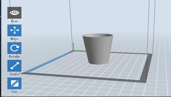
30 Main Interface Overview The screenshot below shows the three main elements of the software - the Menus, the Icons, and the Build Plate. The icons have the functions listed in the table below. Icon Load Function Loads a model or Gcode file. FlashPrint supports.stl,.obj, and.fpp model files. You can also load a.png,.jpg,.jpeg, or.bmp file and FlashPrint will generate a model from the image. See the Generating a Model section for details. Enters the Support Edit mode. Supports 30
31 Print Prints directly from FlashPrint via a USB or wireless connection or exports a Gcode file to the SD card. Views the FlashPrint home screen from one of six viewing angles. View Move Moves the model around on the X/Y plane. Hold the SHIFT key then click to move the mode along the Z axis. Turns and rotates the model. Rotate Scales the size of the model. Scale Cuts the model into several parts. Cut 31

32 Selects the right or left extruder for printing. Extruder Loading a File FlashPrint supports six different ways to load a model or Gcode file, as outlined below. Click the Load icon on the main interface, then select the file. Drag and drop the file onto the main interface. Click File > Load File, then select the file. Click File > Load Examples to load one of the sample files. Click File > Recent Files, then select the file from the list of recently used files. Drag and drop the file onto the FlashPrint icon on the desktop to launch FlashPrint and load the file. Generating a Model FlashPrint can generate a 3D model file from a.png,.jpg,.jpeg, or.bmp image file. When you load the image file, the following dialog box will be displayed, which allows you to set several model parameters. Shape: Determines the basic shape of the model. You can select Plane, Tube, Canister, Lamp, or Seal basic shapes. Mode: Selects whether the light or dark portions of the image will be the high points of the model. Maximum Thickness: Sets the Z value of the model. 32


33 Base Thickness: Sets the minimum raft thickness. The default value is 0.5mm. Width: Sets the X value of the model. Depth: Sets the Y value of the model. Bottom Thickness: Sets the thickness of the bottom of tube, canister, and lamp type models. Top Diameter: Sets the diameter for the top of tube, canister, and lamp type models. Bottom Diameter: Sets the diameter for the bottom of tube, canister, and lamp type models. The following screenshots illustrate the five basic shapes. Plane Tube 33


34 Canister Lamp Seal 34
35 Changing Views You can change the camera angle in relation to the model and build area using a variety of methods. Drag: Click the View icon, then drag the camera using one of the following methods. Left click and hold, then move the mouse. Click and hold the mouse wheel, then scroll up or down. Hold down the SHIFT key, right click and hold, then move the mouse. Rotate: Click the View icon, then rotate the camera using one of the following methods. Right click and hold, then move the mouse. Hold down the SHIFT key, left click and hold, then move the mouse. Scale: Scroll the mouse wheel up or down to zoom the camera in or out. Set View: You can select one of six preset camera angles using one of the following methods. Click the View menu, then select one of the six options from the drop-down list. Click the View icon, then click it again and a submenu will appear with six options for selection. Reset View: You can reset the camera angle to the default using one of the following methods. Click the View menu, then select Home View. Click the View button, the click it again and a submenu will appear. Select the Reset option. Show Model Outline: You can set FlashPrint to show the model outline highlighted in yellow. To do so, click the View menu, then select the Show Model Outline option. Show Steep Overhang: When the intersection angle between the model surface and a horizontal line is within the overhang threshold value, the surface has steep overhang and is shown in red when Show Steep Overhang is enabled. To enable or 35
36 disable Show Steep Overhang, click the View menu, then select the Show Steep Overhang entry. The default threshold value is 45 degrees. Model Manipulation You can manipulate the model using a variety of methods. Move: Click on the model to select it. You can then move it around the build area in a variety of ways. To move the model horizontally in the X/Y plane, left click and hold on the model, then move the mouse. To move the model vertically in the Z plane, hold down the SHIFT key, the left click and hold on the model, then move the mouse. Click the Move button, then enter the distance value. Click Reset to reset the distance values. Note: After moving the model, click Center > On Platform to ensure that the model is in the build area and in contact with the build platform. Rotate: Click on the model to select it. You can them rotate the model in all three planes in a variety of ways. Click the Rotate icon and three mutually perpendicular rings will appear around the model. Click and hold on one ring and move the mouse to rotate the model in that plane. Click the Rotate icon, then manually enter rotation angle values. Click Reset to reset the rotation angle values. Scale: Click on the model to select it. You can then scale it in a variety of ways. Click the Scale icon, then hold the button and move the mouse to change the scale. The corresponding values will display near the model. Click the Scale icon, then enter scales values for the X, Y, and Z axes. Click the Scale icon, then click the Maximum button to get the largest size possible for the build area. 36


37 Click the Scale icon, then click the Reset button to reset the size of the model. Note that if the Uniform Scaling radio button is enabled, it will scale the model in proportion when changing any size value. Cut: Click the model to select it, then double-click the Cut icon to set the cut plane in a variety of ways. Left click and drag the cursor across the model to set the cut angle. Select the X Plane option to cut the model vertically. Select the Y Plane option to cut the model vertically. 37


38 Select the Z Plane option to cut the model horizontally. Extruder Double-click the Extruder icon to select the left and/or right extruder for printing. 38


39 Supports Because 3D printing is an additive process, each layer of filament needs a base to be built on. The printer can gradually increase the layer size, so long as the overhang angle is less than about 45 degrees. Otherwise, you need to create support elements to serve as the base for adding additional layers. To edit the supports, click the Edit menu, then select the Supports entry. Alternatively, click the Supports icon. Click the Back button when finished editing the supports. Support Options: Click the Support Options button to display the Support Options dialog. You can select Treelike or Linear supports. Treelike supports are built at angles, while Linear supports are linear, vertical supports for the overhanging elements. When you click the OK button, the software will generate the appropriate support structures. If the model already has supports, the software will judge whether the existing supports need to be deleted or not on the basis of the type of existing support, and display the corresponding prompt to let you make the choice. 39
40 Auto Supports: Click the Auto Supports button to allow the software to judge where supports are needed and will generate corresponding treelike or linear supports. If the model already has supports, the software will delete them and new supports will be generated. Add Supports: Click the Add button to manually generate supports. Move the cursor to the position where a support is needed, left click to choose the starting point, then while holding down the mouse button, drag the mouse to the termination point. The supports preview will be displayed with the support highlighted. If the support surface doesn't need support or the support column angle is too large, the support will not be generated. Clear Supports: Click the Clear Supports button to remove all existing supports. If you change your mind, click the Undo option or press CTRL+Z. Delete Supports: Click the Delete Supports button to remove individual supports. Click the cursor on the support you want to remove to highlight that support and all subnode supports, then click the left mouse button to delete the highlighted support. 40

41 Printing a Model Click the Print icon on the main interface to slice the model and print the resulting Gcode file, either directly from FlashPrint or by first exporting it to the SD card. Preview: Check the Preview box to preview the model before slicing and printing. Print When Slice Done: Check the Print When Slice Done box to start the print as soon as the slice is completed. Material Type: Select the filament type in use. Supports: Enable or disable the creation of supports. Raft: Enables or disable a Raft, which is several layers of material on the build plate to help with model adhesion. Wall: Check the Wall box to help clear leaking filament from a second extruder during dual color printing. Brim: Check the Brim box to print a ring of filament around the model to help prevent warping and assist with bed adhesion. Resolution: For ABS and PLA printing, you can choose Low, Standard, or High resolution. For PLA printing, you can also choose Hyper. The higher the resolution, the smoother the model surface, but at a corresponding cost in print speed. 41
42 More Options: Click the More Options button to reveal tabs with additional options. Layer: Click the Layer tab to reveal the layer options. Layer Height: Sets the thickness of each layer. The thinner the layer, the smoother the model surface, but at a corresponding cost in print speed. First Layer Height: Sets the thickness of the first layer of the model, which affects how well the model adheres to the build plate. The maximum thickness is 0.4mm and the default value is usually sufficient. Shell: Click the Shell tab to reveal the shell options. Perimeter Shells: Sets the number of perimeter shells. The maximum value is 10. Top Solid Layers: Sets the number of solid layers at the top of the model. The maximum value is 30 and the minimum is 1. Bottom Solid Layers: Sets the number of solid layers at the bottom of the model. The maximum value is 30 and the minimum is 1. Infill: Click the Infill tab to reveal the infill options. Infill is the structure that is printed inside the model. Infill directly affects the strength of the printed mode. Fill Density: Sets the fill density in 5% increments. A 100% density results in a solid model, while a 0% density results in no infill. Fill Pattern: Allows you to select the shape of the infill structure. You can select Line, Hexagon, or Triangle. Combine Infill: You can select the layers for combining according to the layer thickness. The combined thickness should not exceed 0.4mm. The Every N Layers option is for all infill, while the Every N Inner Layers affects only the inner infills, which generally save print time. 42
43 Speed: Click the Speed tab to reveal the speed settings. Print Speed: Determines the speed that the extruder moves while printing filament. It can be set from 10 to 200 mm/sec in 10mm/sec increments. The slower the speed, the higher quality the resulting printed models. For PLA printing, 80mm/sec is recommended. Travel Speed: Determines the speed that the extruder moves while moving from place to place and not actively printing filament. It can be set from 10 to 200 mm/sec in 10mm/sec increments. The slower the speed, the higher quality the resulting printed models. For PLA printing, 100mm/sec is recommended. Temperature: Click the Temperature tab to reveal the temperature options. Right Extruder: Sets the operating temperature of the extruder from 0 to 248 C, in 5 C increments. Set the temperature according to the type of filament being printed. Platform: Sets the operating temperature of the build platform from 0 to 120 C, in 5 increments. Set the temperature according to the type of filament being printed. Others: Click the Others tab to reveal additional options. Pause At Heights: Sets the height at which the print will automatically be paused. This is usually done to allow you to change filament at one or points. Click the Edit button to set the pause point(s). The print can be paused anywhere from 1 to 59.9 mm. 43


44 File Menu The File Menu contains the following options. New Project: Click File > New Project or press CTRL+N to create a new, blank project. A project saves in one place all the models in the scene, including positions, supports, and settings. If there are any unsaved changes to a previously loaded project, you will be prompted to save the changes. Save Project: Click File > Save Project or press CTRL+S to save the current project. Projects files have a.fpp suffix. Load File: Click File > Load File or press CTRL+O to load a model, Gcode, or project file. Save As: Click File > Save As to save the project or model file. Examples: Click File > Examples to load one of four built-in sample models. Recent Files: Click File > Recent Files to choose from a list of recently loaded files. Preferences: Click File > Preferences to set several General and Print preferences. Language: Allows you to select the language used in FlashPrint. Font Size: Allows you to set the size of the font used in FlashPrint. You can select Small, Medium, or Large. Check for Updates after start up: Determines whether FlashPrint will automatically check for the existence of software or driver updates. Auto layout newly-imported model: Determines whether the software will automatically adjust the position of a model immediately after it is loaded. 44
45 Printing Window Type: Allows you to choose the Basic (default) print dialog or the Expert dialog, with many more individual settings. Quit: Click File > Quit or press ALT+F4 to exit FlashPrint. If there are any unsaved changes to your project or model, you will be prompted to save the changes. Edit Menu The Edit Menu contains the following options. Undo: Click Edit > Undo or press CTRL+Z to undo the last change. In most cases, you can undo multiple changes, one at a time. Redo: Click Edit > Redo or press CTRL+Y to redo the last change that was undone. In most cases, you can redo multiple undos. Empty Undo Stack: Click Edit > Empty Undo Stack to clear the software's memory of recent undos. This has the same effect as saving and reloading the project or model file. Select All: Click Edit > Select All or press CTRL+A to select all models in the scene. Duplicate: Click Edit > Duplicate or press CTRL+V to copy the selected model(s). Delete: Click Edit > Delete or press the Del key to delete the selected model(s). Auto Layout All: Click Edit > Auto Layout All to automatically arrange the model(s) on the build platform. You will be prompted to set the distance between models, which can be from 1.0 to 50.0 mm. Mirror Model: Click Edit > Mirror Model to mirror the selected model(s) in the X, Y, or Z planes. Repair Models: Click Edit > Repair Models to correct any errors in the selected model(s). Supports: Click Edit > Supports to enter Support Edit mode. 45
46 Print Menu The Print Menu contains the following options. Connect Machine: Click Print > Connect Machine to establish a USB or Wi-Fi connection to the printer. This option is not available if the printer is already connected. Disconnect: Click Print > Disconnect to break a connection with the printer. This option is not available if there is no connection with the printer. Print: Click Print > Print or press CTRL+P to open the print dialog. Machine Type: Click Print > Machine Type. Allows you to select the specific model of 3D printer to use with FlashPrint. This printer is the MP Inventor. View Menu The View Menu contains the following options. Home View: Sets the camera to the default position. Top View: Sets the camera to look directly down onto the build area. Bottom View: Sets the camera to look directly up towards the build area. Left View: Sets the camera to look at the build area from the left. Right View: Sets the camera to look at the build area from the right. Front View: Sets the camera to look at the build area from the front. Back View: Sets the camera to look at the build area from the rear. Show Model Outline: Puts a yellow outline around the model. Show Steep Overhang: Highlights in red those portions of the model that requires supports. 46

47 Tools Menu The Tools Menu contains the following options. Control Panel: Click Tools > Control Panel to modify the printer's settings from within FlashPrint. Note that if you are not connected to the printer, you will be prompted to do so before the Control Panel can be displayed. Jog Mode: The Jog Mode section allows you to select the distance that the extruder and build plate move with each mouse click. Six Blue Arrow Buttons: The buttons allow you to manually move the extruder and build plate. The amount they will move with each click of the mouse is determined by the Jog Mode settings. Stop: Click the Stop button to abort any current movement. XYZ Coordinates: Displays the current position of the extruder and build plate. You cannot edit the displayed values. Make Current Position Zero: Click the Make Current Position Zero button to set the zero position for the three axes. Center XYZ: Click a Center button to move the extruder or build plate to the zero position for that axis. 47
48 Set X/Y Speed: Sets the speed at which the extruder moves. Set Z Speed: Sets the speed at which the build plate moves. Limit Switch: Displays the status of the limit switches on each axis. If the extruder or build plate are not moved to its maximum positions, the status will show Not Triggered in green. If the extruder or build plate has been moved to its maximum position, the status will show Triggered in red. Stepper Motor Controls: Click the Enable button to lock the stepper motor so that it does not allow movement. Click Disable to unlock the stepper motor so the extruder and build plate can be manually moved. LED Color: Allows you to set the LED color of the Inventor printer. Motor Speed (RPM): Controls the speed of the filament feed wheel. Extruder Duration: Controls the motor rotation time. Forward: Feeds filament to the extruder. Reverse: Unloads filament from the extruder. Stop: Stops motor movement when feeding or unloading filament. Temperature Control: Allows you to set the target extruder or platform temperature. Click the Apply button to start heating. Update Firmware: Allows you to update the printer's firmware. On Board Preferences: Allows you to check the printer's name. Machine Information: Displays information about the printer, including the firmware version. 48
49 Help Menu The Help Menu contains the following options. First Run Wizard: Re-runs the wizard that automatically runs the first time FlashPrint is run. Help Contents: Allows you to read the help files. Feedback: Allows you to submit feedback. Check For Updates: Checks for FlashPrint updates. About FlashPrint: Displays FlashPrint version information. CONNECTING THE PRINTER There are three ways of connecting the FlashPrint software with the Inventor printer - a wired USB connection or a wireless Wi-Fi connection in AP mode or STA (Station) mode. USB Connection Perform the following steps to connect your PC to the Inventor printer using a wired USB connection. 1. Plug one end of the included USB cable into the USB port on the printer, then plug the other end into an available USB port on your computer. 2. Power on the printer and your computer, then start the FlashPrint software. 3. Click Print > Connect Machine. 4. Set the Connection Mode to USB and set the Select Machine option to the Inventor printer. If the printer does not appear in the Select Machine list, click the Rescan button. If it still does not appear, reinstall the driver software. 49

50 Wi-Fi Connection Perform the following steps to connect your PC to the Inventor printer using a Wi-Fi connection. Note that printing from an SD card is disabled when Wi-Fi is enabled. 1. Power on the printer and your computer. 2. On the printer, select Tool > Setting > WIFI > WIFI ON. 3. Open your computer's wireless network settings and scan for available Wi-Fi signals. Select the Inventor1 entry, then click Connect. 4. Open your internet browser. Type and press the Enter key on your keyboard. Enter the username and password to login. The default username and password are both admin. The control panel will appear after successful login. 5. Click the WiFi Set tab on the left, then set the WiFi Work Mode to AP mode or STA mode, then click Restart to make the changes take effect. AP mode configures the printer's Wi-Fi radio to act as a Wi-Fi Hotspot/Access Point (AP). You then set your computer's network settings to directly connect to the printer's Wi-Fi AP, rather than your regular Wi-Fi AP. 50
51 STA mode configures the printer's Wi-Fi radio to connect to your regular Wi-Fi AP. In STA mode you do not need to change your computer's network settings and can continue to use your Wi-Fi AP, as normal. If you choose to use AP mode, you can set the network name (Inventor1) and password of the hotspot. If you don't want to use a password, enter NONE. Click the Save button and restart it. Connect your PC to the network named Inventor1 (or the name you set). Open FlashPrint, then click Print > Connect Machine. Select Wi-Fi as the Connect Mode and enter the IP Address, as shown on the Inventor's screen. Click Connect. 51
52 If you choose you use STA mode, input the SSID and password of your existing Wi-Fi connection. If your Wi-Fi connection does not use a password, enter NONE into the password field. Then click the Save button and restart it. Restart the Inventor printer, then open the WIFI Screen. 52

53 Turn on the Inventor again and connect your computer to the network. Open FlashPrint, then click Print > Connect Machine. Select Wi-Fi as the Connect Mode and enter the IP Address, as shown on the Inventor's screen. Click Connect. If you want to switch between AP and STA modes, touch the Reset button on the WIFI Screen. UPDATING THE FIRMWARE Each time you start FlashPrint, it will automatically detects and downloads the up-to-date firmware. If an update is available, a dialog box will appear to remind you of the update. Perform the following steps to update the firmware. 1. Click Tools > Update firmware. You must sever any existing connection with the printer before updating. If a connection exists, it will prompt you to cut the connection. Click the Yes button to cut the connection. 2. Choose the corresponding printer type and firmware version, then click OK in the firmware update dialog. After confirming that there is no printer connection, the software will automatically update the firmware. 53
54 3. Reboot the Inventor printer and wait 4-5 seconds until the update progress bar is displayed. When the update is finished, it will return to the Top Menu. 4. Touch the Tool button, then touch About to check that the version is correct. PRINTING There are two basic modes of printing: single extrusion and dual extrusion. With single extrusion printing, you can choose which print head to use for making the print. Dual extrusion printing is useful if you want to print with two color or print complex models that require supporting material. Perform the following steps to print a model on the Inventor printer from a Gcode file saved to the SD card. Generating Gcode 1. Plug the included SD card into an SD card reader on your computer. 2. Double-click the FlashPrint shortcut to launch the software. 54


55 3. Click Print > Machine Type and select the MP Inventor entry. 4. Click the Load icon to load a.stl model file. The model will display within the build area. 5. Double-click the Move icon, then click the On the Platform and Center buttons to ensure the model is in contact with the center of the build platform. 6. Click the Print icon, then change the settings as appropriate for your filament type and model. Preview: Check the Preview box if you want to preview the model after slicing is done. Print When Slice Done: Because we are printing from the SD card, uncheck this box to save the Gcode file to the SD card. Machine Type: Select MP Inventor. 55
56 Material Right: Select the type of filament you are using. Material Left: Select the type of filament you are using. Supports: If your model has overhanging elements, enable the Supports option. Raft: It is recommended to enable the Raft option. Resolution: It is recommended to select the Standard option. More Options: It is recommended to leave them at the default values. 7. Click OK to save the Gcode file to the SD card. You can rename the file as desired and save it as either a.g or.gx file. Files with a.gx extension can be previewed, while.g files cannot. 8. Eject the SD card, then plug it into the SD card slot on the printer. 9. Power on the Inventor printer. 10. Ensure that the build plate is leveled and that filament is loaded. 11. Touch the Print button on the printer display. 12. Touch the SD card button, then locate and load your model file. 56
57 13. Touch the Print button to begin printing. The printer will begin heating the extruder and/or platform, then will begin printing once the target temperatures are reached. Touch the Stop button at any time to cancel the print. Touch the Pause button to pause the print. USING THE CAMERA The Inventor printer includes a camera, which allows you to monitor the print on your phone. Download and install the XMEye app from the App store. After installing the app, perform one of the following connection methods to use the camera. Direct Login 1. If the printer is not already powered on, flip the power switch to the ON position. Wait for the printer to stabilize, then touch the Tool button on the Top Menu, then touch the Setting button. 57
58 2. Touch the Camera button, then touch the On button to turn the camera on. You will see the words Turned on in the upper left corner of the screen. 3. Open your phone's Wi-Fi settings and scan for the camera's Wi-Fi radio. The camera name always starts with xmjp, but will have different combinations of letters and numbers for the rest of the name. If the hotspot does not appear in the list, touch the Reset button on the Camera Screen. Select the xmjp entry, then enter the password Open the XMEye app after your phone has successfully connected with the camera's Wi-Fi signal. 5. Tap Direct Login to review the video. The camera is now directly connected to the phone. The video will interrupt if the phone moves out of range. 58

59 Local Login 1. If the printer is not already powered on, flip the power switch to the ON position. Wait for the printer to stabilize, then touch the Tool button on the Top Menu, then touch the Setting button. 2. Touch the Camera button, then touch the On button to turn the camera on. You will see the words Turned on in the upper left corner of the screen. 3. Connect your mobile phone to an available Wi-Fi hotspot, then open the XMEye app. Tap Local Login, then tap the + in the upper right to add a device. 59


60 4. Tap WiFi Config, then enter the password for your Wi-Fi access point. Check the Ensure the indicator and Device operation options, then tap Complete all the above operation. 5. Touch the Reset button on the printer's screen, then tap Yes in the dialog that appears on your phone. Note that the Android version of the app does not display this dialog. 60


61 6. The app starts to scan for the camera. If a green point appears, the camera is properly configured. If not, you will need to start over from the beginning. Tap the green point on your phone. 7. You can now see the camera in the device list. Tap it to watch the video. 8. After adding the device, the camera Wi-Fi hotspot signal xmjp-beye-xxxx will disappear. You are now connected to the internet and can review the video from anywhere you have internet access. 61

62 RESUME PRINTING The MP Inventor has the ability to automatically resume printing in the event of a power outage. Perform the following steps to enable print resuming. 1. If the printer is not already powered on, flip the power switch to the ON position. Wait for the printer to stabilize, touch the Tool button on the Top Menu, then touch the Setting button. 2. Touch the Resume Print button to enable print resuming. 3. If the printer loses power during a print, the following dialog will appear after power is reapplied. Touch the Yes button to resume printing. 62
63 SPECIFICATIONS Model Printer Name Inventor Number of Extruders 2 Print Technology Screen Type Build Area Layer Resolution Build Accuracy Positioning Accuracy Filament Diameter Filament Types Nozzle Diameter Build Speed Software Supported Input Formats Supported Output Formats Supported Operating Systems Input Power Connectivity Dimensions Weight Fused Filament Fabrication (FFF) 3.5" color IPS touch screen 230 x 150 x 160 mm mm ±0.1mm XY Axis: 0.011mm, Z Axis: mm 1.75mm ±0.07mm ABS, PLA, Conductive PLA, Flexible Filament 0.4mm 10~200 mm/sec FlashPrint 3MF,.STL,.OBJ,.FPP,.BMP,.PNG,.JPG,.JPEG.G,.GX Windows XP and later (32-bit and 64-bit), Mac OS X, Linux 100 ~ 240 VAC, 50/60 Hz, 4.5A-2.5A USB cable, SD card, Wi-Fi 19.1" x 13.5" x 15.8" (485 x 344 x 402 mm) 23.6 lbs. (10.7 kg) 63
64 TECHNICAL SUPPORT Monoprice is pleased to provide free, live, online technical support to assist you with any questions you may have about installation, setup, troubleshooting, or product recommendations. If you ever need assistance with your new product, please come online to talk to one of our friendly and knowledgeable Tech Support Associates. Technical support is available through the online chat button on our website during regular business hours, 7 days a week. You can also get assistance through by sending a message to tech@monoprice.com REGULATORY COMPLIANCE Notice for FCC This device complies with Part 15 of the FCC Rules. Operation is subject to the following two conditions: (1) This device may not cause harmful interference, (2) This device must accept any interference received, including interference that may cause undesired operation. Warning: Changes or modifications not expressly approved by the party responsible for compliance could void the user's authority to operate the equipment. This equipment has been tested and found to comply with the limits for a Class B digital device, pursuant to Part 15 of the FCC Rules. These limits are designed to provide reasonable protection against harmful interference in a residential installation. This equipment generates uses and can radiate radio frequency energy and, if not installed and used in accordance with the instructions, may cause harmful interference to radio communications. However, there is no guarantee that interference will not occur in a particular installation. If this equipment does cause harmful interference to radio or television reception, which can be determined by turning the equipment off and on, the 64
65 user is encouraged to try to correct the interference by one or more of the following measures: Reorient or relocate the receiving antenna. Increase the separation between the equipment and receiver. Connect the equipment into an outlet on a circuit different from that to which the receiver is connected. Consult the dealer or an experienced radio/tv technician for help. Notice for Industry Canada This Class B digital apparatus complies with Canadian ICES-003 Cet appareil numerique de la classe B est conforme a la norme NMB-003 du Canad EU Declaration of Conformity Monoprice, Inc. declares the product described within this user guide or manual is in compliance with below applicable directives. The full text of the EU Declaration of Conformity is available at the following internet address: &seq=1&format=2 or the CE DoC can be found within this user manual EMC Directive 2004/108/EC Low Voltage Directive 2014/35/EU RoHS2 Directive 2011/65/EU WEEE Directive 2012/19/EC Packaging & Packaging Waste Directive 94/62/EC REACH Directive 1907/2006/EC 65
66 WEEE Information User information for consumer products covered by EU Directive 2012/19/EU on Waste Electric and Electronic Equipment (WEEE) This document contains important information for users with regards to the proper disposal and recycling of Monoprice products. Consumers are required to comply with this notice for all electronic products bearing the following symbol: For Consumers in the European Union: This EU Directive requires that the product bearing this symbol and or its packaging must not be disposed of with unsorted municipal waste. The symbol indicates that this product should be disposed of separately from regular household waste streams. It is your responsibility to dispose of this and other electrical and electronics products via designated collection facilities appointed by the government or local authorities. Correct disposal and recycling will help prevent potential negative consequences to the environment and human health. For more detailed information about the disposal of your unwanted product, please contacts your local authorities, waste disposal service, or the shop where you purchased the product. 66

67 Safety Notice WARNING: Do not use this product near water, for example, in a wet basement or near swimming pool or in an area where accidental contact with water or liquid might occurs WARNING: Avoid using this product during an electrical storm. There may be a remote risk of electric shock from the surge caused by lightning WARNING: The external power adapter or AC power cord is the equipment's disconnection device. The power outlet must be located nearby the equipment and its access must be easy WARNING: Use this product in a well-ventilated area Wi-Fi is a registered trademark of Wi-Fi Alliance. Microsoft and Windows are either registered trademarks or trademarks of Microsoft Corporation in the United States and/or other countries. Apple, Mac, and OS X are trademarks of Apple Inc., registered in the U.S. and other countries. Linux is the registered trademark of Linus Torvalds in the U.S. and other countries. SD is a trademark or registered trademark of SD-3C, LLC in the United States, other countries, or both. Android is a trademark of Google Inc. 67
MP Education Guider II 3D Printer
 MP Education Guider II 3D Printer P/N 30527 User's Manual CONTENTS SAFETY WARNINGS AND GUIDELINES... 5 CUSTOMER SERVICE... 6 PACKAGE CONTENTS... 6 PRODUCT OVERVIEW... 8 Front View... 8 Top View... 8 Right
MP Education Inventor II 3D Printer
 MP Education Inventor II 3D Printer P/N 30525 User's Manual CONTENTS SAFETY WARNINGS AND GUIDELINES... 5 CUSTOMER SERVICE... 6 PACKAGE CONTENTS... 6 PRODUCT OVERVIEW... 8 Front View... 8 Top View... 8
Select Mini 3D Printer V2
 Select Mini 3D Printer V2 P/N 15365, 21711, 21872, 24166 User's Manual CONTENTS SAFETY WARNINGS AND GUIDELINES... 3 INTRODUCTION... 4 FEATURES... 4 CUSTOMER SERVICE... 5 PACKAGE CONTENTS... 5 PRODUCT OVERVIEW...
Select Mini Pro 3D Printer
 Select Mini Pro 3D Printer P/N 33012 User's Manual CONTENTS SAFETY WARNINGS AND GUIDELINES... 3 INTRODUCTION... 4 FEATURES... 4 CUSTOMER SERVICE... 5 PACKAGE CONTENTS... 5 PRODUCT OVERVIEW... 6 SETUP...
MONOPRICE. Blackbird 4K Pro 1x2 Ultra Slim HDMI Splitter. User's Manual P/N 21612
 MONOPRICE Blackbird 4K Pro 1x2 Ultra Slim HDMI Splitter P/N 21612 User's Manual SAFETY WARNINGS AND GUIDELINES Please read this entire manual before using this device, paying extra attention to these safety
MONOPRICE. ShowPony 12-Watt LED Derby FX Light (RGBW) User's Manual P/N
 User's Manual P/N") MONOPRICE ShowPony 12-Watt LED Derby FX Light (RGBW) P/N 612900 User's Manual CONTENTS SAFETY WARNINGS AND GUIDELINES... 3 FEATURES... 5 CUSTOMER SERVICE... 5 PACKAGE CONTENTS... 5 DIMENSIONS DIAGRAM...
MONOPRICE ShowPony 12-Watt LED Derby FX Light (RGBW) P/N 612900 User's Manual CONTENTS SAFETY WARNINGS AND GUIDELINES... 3 FEATURES... 5 CUSTOMER SERVICE... 5 PACKAGE CONTENTS... 5 DIMENSIONS DIAGRAM...
MONOPRICE. Blackbird HDMI Bi-Directional Switch. User's Manual P/N 24280
 MONOPRICE Blackbird HDMI Bi-Directional Switch P/N 24280 User's Manual SAFETY WARNINGS AND GUIDELINES Please read this entire manual before using this device, paying extra attention to these safety warnings
SAFETY WARNINGS AND GUIDELINES
 1 SAFETY WARNINGS AND GUIDELINES Do not expose this device to water or moisture of any kind. Do not place drinks or other containers with moisture on or near the device. If moisture does get in or on the
MONOPRICE. MP Mini Delta 3D Printer. User's Manual P/N 21666
 MONOPRICE MP Mini Delta 3D Printer P/N 21666 User's Manual CONTENTS SAFETY WARNINGS AND GUIDELINES... 3 INTRODUCTION... 4 FEATURES... 4 CUSTOMER SERVICE... 5 PACKAGE CONTENTS... 5 PRODUCT OVERVIEW... 6
Select Mini 3D Printer V2
 Select Mini 3D Printer V2 P/N 15365, 21711, 21872, 24166, 34619, 34620 User's Manual CONTENTS SAFETY WARNINGS AND GUIDELINES... 3 INTRODUCTION... 4 FEATURES... 4 CUSTOMER SERVICE... 5 PACKAGE CONTENTS...
SB Channel Soundbar with Built-in Subwoofer
 SB-100 2.1-Channel Soundbar with Built-in Subwoofer P/N 34710 User's Manual SAFETY WARNINGS AND GUIDELINES Please read this entire manual before using this device, paying extra attention to these safety
HDMI and USB KVM Extender
 HDMI and USB KVM Extender P/N 34898 User's Manual SAFETY WARNINGS AND GUIDELINES Please read this entire manual before using this device, paying extra attention to these safety warnings and guidelines.
PowerSpec Ultra 3D Printer Start-up Guide Table of Contents
 PowerSpec Ultra 3D Printer Start-up Guide Table of Contents 1 What's Included in the Box?...Page 3 2 Un-boxing.Page 4 3 Initial Hardware Installation Page 6 4 Software Instruction.Page 8 5 Filament Page
Dreamer Series User Manual
 Dreamer Series User Manual Welcome to the world of the Dreamer. To ensure that you have the best possible user experience, it s important that you follow this user manual. Let s get started! In Parts I
MONOPRICE. MP Mini Delta 3D Printer. User's Manual P/N 21666, 24168, 24169
 MONOPRICE MP Mini Delta 3D Printer P/N 21666, 24168, 24169 User's Manual CONTENTS SAFETY WARNINGS AND GUIDELINES... 3 INTRODUCTION... 4 FEATURES... 4 CUSTOMER SERVICE... 5 PACKAGE CONTENTS... 5 PRODUCT
MP Voxel 3D Printer. P/Ns 33820, 35880, User's Manual
 MP Voxel 3D Printer P/Ns 33820, 35880, 35881 User's Manual CONTENTS SAFETY WARNINGS AND GUIDELINES... 4 FEATURES... 6 CUSTOMER SERVICE... 6 PACKAGE CONTENTS... 7 PRODUCT OVERVIEW... 8 Internal View...
SAFETY WARNINGS AND GUIDELINES... 3 INTRODUCTION... 4 FEATURES... 4 CUSTOMER SERVICE... 4 PACKAGE CONTENTS... 5 NAVIGATING THE MENU SYSTEM...
 CONTENTS SAFETY WARNINGS AND GUIDELINES... 3 INTRODUCTION... 4 FEATURES... 4 CUSTOMER SERVICE... 4 PACKAGE CONTENTS... 5 NAVIGATING THE MENU SYSTEM... 5 UNPACKING AND SETUP... 6 FINE TUNING PLATFORM HEIGHT...
Unity 100-watt Bridgeable Power Amp
 Unity 100-watt Bridgeable Power Amp P/N 18513 User's Manual CONTENTS SAFETY WARNINGS AND GUIDELINES... 3 INTRODUCTION... 4 FEATURES... 4 CUSTOMER SERVICE... 5 PACKAGE CONTENTS... 5 PRODUCT OVERVIEW...
MONOPRICE. Blackbird 4K HDMI 1x8 Splitter/Extender. User's Manual P/N 18787
 MONOPRICE Blackbird 4K HDMI 1x8 Splitter/Extender P/N 18787 User's Manual CONTENTS SAFETY WARNINGS AND GUIDELINES... 3 INTRODUCTION... 4 FEATURES... 4 CUSTOMER SERVICE... 4 PACKAGE CONTENTS... 5 PRODUCT
Wireless Smart MOTION SENSOR
 Wireless Smart MOTION SENSOR P/N 33050 User s Manual CONTENTS INTRODUCTION... 3 FEATURES... 3 CUSTOMER SERVICE... 3 PACKAGE CONTENTS... 4 APPLICATIONS... 4 PRODUCT OVERVIEW... 5 PHYSICAL INSTALLATION...
Wireless Smart Water Leak/Flood Sensor
 Wireless Smart Water Leak/Flood Sensor P/N 33124 User's Manual CONTENTS INTRODUCTION... 3 FEATURES... 3 CUSTOMER SERVICE... 3 PACKAGE CONTENTS... 4 PRODUCT OVERVIEW... 5 PHYSICAL INSTALLATION... 5 APP
3-7. Set Materials (Touch Screen) Set Materials (Software) Material Weight adjustment (grams) Current material weight. Increase.
 Set Materials (Software) Material Weight adjustment (grams) Current material weight. Increase.") Set Materials (Touch Screen) 3-7 Decrease Material Weight adjustment (grams) Increase Current material weight Save current settings Stop extrusion and heating Back withdraw material change material extrude
Set Materials (Touch Screen) 3-7 Decrease Material Weight adjustment (grams) Increase Current material weight Save current settings Stop extrusion and heating Back withdraw material change material extrude
SAFETY WARNINGS AND GUIDELINES
 SAFETY WARNINGS AND GUIDELINES Please read this entire manual before using this device, paying extra attention to these safety warnings and guidelines. Please keep this manual in a safe place for future
User Manual V 0.1. Download the full user manual at
 User Manual V 0.1 Download the full user manual at www.afinia.com/support Index Chapter 1 Product Description Chapter 2 Prepare for Your First 3D Print Chapter 3 Machine Settings Chapter 4 Print Settings
MONOPRICE. Maker Select Pro Ultimate 3D Printer. User's Manual P/N 15710, 21873, 24167
 MONOPRICE Maker Select Pro Ultimate 3D Printer P/N 15710, 21873, 24167 User's Manual CONTENTS SAFETY WARNINGS AND GUIDELINES... 3 INTRODUCTION... 4 FEATURES... 4 CUSTOMER SERVICE... 4 PACKAGE CONTENTS...
MONOPRICE. Blackbird 4x4 HDMI Matrix/Extender with 4 Receivers. User's Manual P/N 21905
 MONOPRICE Blackbird 4x4 HDMI Matrix/Extender with 4 Receivers P/N 21905 User's Manual CONTENTS SAFETY WARNINGS AND GUIDELINES... 3 INTRODUCTION... 4 FEATURES... 4 CUSTOMER SERVICE... 5 PACKAGE CONTENTS...
3D BIO-PRINTER. USER MANUAL Version D Cultures
 3D BIO-PRINTER 3D Cultures USER MANUAL Version 2.0 Product pictures are for reference only. Color(s), size, parts, and interface may vary. Preheating is not recommend with the use of cells. This manual
Stage Right Party Wash FX 1-Watt x54 LED (RGB) with Pie Control
 with Pie Control") Stage Right Party Wash FX 1-Watt x54 LED (RGB) with Pie Control P/N 612970 User's Manual SAFETY WARNINGS AND GUIDELINES Please read this entire manual before using this device, paying extra attention to
Stage Right Party Wash FX 1-Watt x54 LED (RGB) with Pie Control P/N 612970 User's Manual SAFETY WARNINGS AND GUIDELINES Please read this entire manual before using this device, paying extra attention to
MONOPRICE. Blackbird 4K 2x7 HDBaseT Splitter Kit. User's Manual P/N 24178
 MONOPRICE Blackbird 4K 2x7 HDBaseT Splitter Kit P/N 24178 User's Manual CONTENTS SAFETY WARNINGS AND GUIDELINES... 3 INTRODUCTION... 4 FEATURES... 5 CUSTOMER SERVICE... 5 PACKAGE CONTENTS... 6 PRODUCT
ideamaker Manual
 ideamaker Manual Using ideamaker... 2 Basic information... 2 What is ideamaker?... 2 Where to download ideamaker?... 2 Install ideamaker... 3 Let s Print!... 6 How to use ideamaker?... 23 Interface...
MONOPRICE. Bluetooth Over-the-Ear Headphones with External Speakers. User's Manual. Model 15276
 MONOPRICE Bluetooth Over-the-Ear Headphones with External Speakers Model 15276 User's Manual SAFETY WARNINGS AND GUIDELINES This device is intended for indoor use only. Do not expose this device to water
User Guide Dreamer Desktop 3D Printer
 User Guide Dreamer Desktop 3D Printer Dreamer User Guide www.ff3dp.com 1 Dreamer User Guide www.ff3dp.com 2 CONTENTS WELCOME TO FLASHFORGE DREAMER A. How to use this manual B. The FlashForge Experience
MONOPRICE. MP 22" IPS FHD Graphic Pen Display. User's Manual P/N 21825
 MONOPRICE MP 22" IPS FHD Graphic Pen Display P/N 21825 User's Manual CONTENTS SAFETY WARNINGS AND GUIDELINES... 3 INTRODUCTION... 4 FEATURES... 4 CUSTOMER SERVICE... 4 PACKAGE CONTENTS... 5 SYSTEM REQUIREMENTS...
Blackbird 4K Multi Format HDMI Converter with 4K Scaler
 Blackbird 4K Multi Format HDMI Converter with 4K Scaler P/N 30918 User's Manual SAFETY WARNINGS AND GUIDELINES Please read this entire manual before using this device, paying extra attention to these safety
USER MANUAL Resolution 0.02mm Speed 300mm/second Software: Wanhao Maker
 1 Duplicator 5S & 5S MINI Desktop 3D Printers USER MANUAL Resolution 0.02mm Speed 300mm/second Software: Wanhao Maker 2014/2015 Wanhao USA 3 Table of Contents Welcome 1 Printer Specifications 2 Unboxing
SAFETY WARNINGS AND GUIDELINES
 1 SAFETY WARNINGS AND GUIDELINES Please read this entire manual before using this device, paying extra attention to these safety warnings and guidelines. Please keep this manual in a safe place for future
MP BT-200 Lightweight Bluetooth Over-the-Ear Headphones
 MP BT-200 Lightweight Bluetooth Over-the-Ear Headphones P/N 33397 User's Manual CONTENTS SAFETY WARNINGS AND GUIDELINES... 3 FEATURES... 4 CUSTOMER SERVICE... 5 PACKAGE CONTENTS... 5 PRODUCT OVERVIEW...6
English. Quick Guide
 English Quick Guide Specification Product Overview Button and Indicator light Unpacking Accessory Checklist Important Safety Notes Extruder module installation Accessory installation XYZware operation
Blackbird HDBaseT Extender Kit
 Blackbird HDBaseT Extender Kit P/N 31055 User's Manual SAFETY WARNINGS AND GUIDELINES Please read this entire manual before using this device, paying extra attention to these safety warnings and guidelines.
MONOPRICE. Blackbird 4K 5x1 HDMI Presentation Switch. User's Manual P/N 21906
 MONOPRICE Blackbird 4K 5x1 HDMI Presentation Switch P/N 21906 User's Manual CONTENTS SAFETY WARNINGS AND GUIDELINES... 4 INTRODUCTION... 4 FEATURES... 5 CUSTOMER SERVICE... 5 PACKAGE CONTENTS... 6 PRODUCT
Blackbird 4K Pro 1x4 HDMI Splitter
 Blackbird 4K Pro 1x4 HDMI Splitter P/N 15259 User's Manual SAFETY WARNINGS AND GUIDELINES Please read this entire manual before using this device, paying extra attention to these safety warnings and guidelines.
SySTIUM TECHNOLOGIES. Assembly Guide. Model 133i
 Assembly Guide Model 133i Radio Frequency Interference Notice (USA) This equipment has been tested and found to comply with the limits for a Class B digital device, pursuant to Part 15 of the FCC Rules,
SAFETY WARNINGS AND GUIDELINES... 4 INTRODUCTION... 5 FEATURES... 5 CUSTOMER SERVICE... 5 PACKAGE CONTENTS... 6 PRODUCT OVERVIEW Front View...
 CONTENTS SAFETY WARNINGS AND GUIDELINES... 4 INTRODUCTION... 5 FEATURES... 5 CUSTOMER SERVICE... 5 PACKAGE CONTENTS... 6 PRODUCT OVERVIEW... 7 Front View... 7 Rear View... 8 Bed Assembly... 9 Front and
SERIES 4600 Ethernet Visual-Pager Display INSTALLATION and SPECIFICATION GUIDE. Manual No. D Revision Date: 08/2016 Control: 1.
 SERIES 4600 Ethernet Visual-Pager Display INSTALLATION and SPECIFICATION GUIDE Manual No. D4600-7010 Revision Date: 08/2016 Control: 1.0 Microframe Corporation 604 South 12th Street Local: 918-258-4839
MONOPRICE. Blackbird 4K HDBaseT Wall Plate Scaler Transmitter. User's Manual P/N 21816
 MONOPRICE Blackbird 4K HDBaseT Wall Plate Scaler Transmitter P/N 21816 User's Manual CONTENTS SAFETY WARNINGS AND GUIDELINES... 3 INTRODUCTION... 3 FEATURES... 4 CUSTOMER SERVICE... 4 PACKAGE CONTENTS...
da Vinci Jr.1.0 April 2016 da Vinci Junior 1.0w 3D Printer da Vinci Jr.1.0w Quick Guide HD23F1JW0N1
 da Vinci Junior 1.0w 3D Printer w Quick Guide P 1 Product Overview A: Filament movement area B: Feed module C: Detector D: Extruder E: Filament F: Print bed G G: SD card port (Storage format: FAT32) H:
elise 3 embedded linux server including safety instructions
 elise 3 embedded linux server including safety instructions Contents Getting Started... 2 Safety and Regulatory Instructions for Elise3... 8 English Getting Started These instructions will help you getting
Instruction Manual. RS 3D Printer
 Instruction Manual RS 3D Printer 1) GENERAL This instruction manual contains important information regarding the installation, operation, maintenance and storage for RS 3D Printer. Please read these instructions
HD40H(X) Performance Series Camera. User Guide
 Performance Series Camera. User Guide") HD31H(X) HD30H(X) HD40H(X) Performance Series Camera User Guide Document 1 2 HD40H(X)/HD30H(X)/HD31H(X) Camera User Guide Thank you for purchasing our product. If there are any questions, or requests,
HD31H(X) HD30H(X) HD40H(X) Performance Series Camera User Guide Document 1 2 HD40H(X)/HD30H(X)/HD31H(X) Camera User Guide Thank you for purchasing our product. If there are any questions, or requests,
Please read this guide before using the printer
 PD-450/450W/480/480W User Guide Please read this guide before using the printer Safety Precautions Safety Precautions Denotes the possibility of serious injury or death Use only recommended power sources.
Blackbird 4K Pro HDBaseT Extender Kit
 Blackbird 4K Pro HDBaseT Extender Kit P/N 31059 User's Manual SAFETY WARNINGS AND GUIDELINES Please read this entire manual before using this device, paying extra attention to these safety warnings and
Copyright 2013 Esselte Leitz GmbH & Co. KG. All rights reserved.
 Copyright 2013 Esselte Leitz GmbH & Co. KG. All rights reserved. Mac, ipad, AirPrint, and OS X are trademarks of Apple Inc., registered in the U.S. and other countries. Google and Google Cloud Print are
MONOPRICE. MP USB Powered 15.6" IPS FHD Graphic Pen Display Tablet. User's Manual P/N 21826
 MONOPRICE MP USB Powered 15.6" IPS FHD Graphic Pen Display Tablet P/N 21826 User's Manual CONTENTS SAFETY WARNINGS AND GUIDELINES... 4 INTRODUCTION... 5 FEATURES... 6 CUSTOMER SERVICE... 6 PACKAGE CONTENTS...
4MP WI-FI PAN TILT CAMERA QUICK START GUIDE ENGLISH
 4MP WI-FI PAN TILT CAMERA QUICK START GUIDE ENGLISH WELCOME! Congratulations on your latest purchase and welcome to the Q-See family. This guide will help get your camera up and running. WHAT S INCLUDED
ideamaker Manual
 ideamaker Manual www.raise3d.com 1 Using ideamaker... 3 1.1 What is ideamaker?... 3 1.2 Where to download ideamaker?... 3 2 Install ideamaker... 4 3 Let s Print!... 9 3.1 Import.STL files... 9 3.2 Slice
SAFETY WARNINGS AND GUIDELINES
 SAFETY WARNINGS AND GUIDELINES This device is intended for indoor use only. Do not expose this device to water or moisture of any kind. Do not place drinks or other containers with moisture on or near
Smartphone Photo Printer
 Smartphone Photo Printer Safety Precautions Safety Precautions Denotes the possibility of serious injury or death Please keep you away at least 20cm distance from printer when printing. Use only recommended
M2 3D Printer V4 M2 3D Printer
 M2 3D Printer V4 Contents 2 Important Safeguards 3 Welcome 4 M2 Features 6 Other products included with your printer 7 Set up 9 Slicing.STL or.obj files 10 Maintenance and Support 11 Warranty 12 About
+Cam Quick Start Guide
 CAUTION RISK OF ELECTRIC SHOCK DO NOT OPEN CAUTION TO REDUCE THE RISK OF ELECTRIC SHOCK, DO NOT REMOVE COVER (OR BACK). NO USER SERVICEABLE PARTS INSIDE, REFER SERVICING TO QUALIFIED SERVICE PERSONNEL.
W10 PRO QUICK START GUIDE
 W10 PRO QUICK START GUIDE GETTING STARTED Thank you for purchasing a Hipstreet product and we hope you enjoy using it. Please visit our website at www.hipstreet.com IMPORTANT SAFETY PRECAUTIONS Always
2 Mesa Ethernet Dock User s Manual
 owner s manual Mesa Ethernet Dock The Mesa Ethernet Dock is an optional accessory that provides an ethernet port for networking, power input jack, USB client port, and a mounting station for the Mesa Rugged
ideamaker Manual
 ideamaker Manual www.raise3d.com 1 Using ideamaker... 3 1.1 What is ideamaker?... 3 1.2 Where to download ideamaker?... 3 2 Install ideamaker... 4 3 Let s Print!... 9 3.1 Import.STL files... 9 3.2 Slice
Quick Installation Guide
 Quick Installation Guide Applicable Models: AS6004U Ver.3.0.0 (2017-4-13) Table of Contents Notices... 3 Safety Precautions... 4 1. Package Contents... 5 2. Optional Accessories... 6 3. Hardware Installation
Q U I C K S T A R T G U I D E
 QUICKSTART GUIDE 2 Top 4 5 6 3 13 14 18 19 16 17 12 1 20 7 8 9 10 15 Left Side Front Right Side Back 11 Bottom 1 Power Button 2 Earphone Connector 3 Front-Facing Camera 4 Speaker 5 Ambient Light Sensor
This user manual has been specially designed to guide you through the functions and features of your device.
 DL102 Cautions This user manual has been specially designed to guide you through the functions and features of your device. 1) Please read this manual carefully before using your device to ensure safe
5-Port USB 3.1 (10Gbps) Combo Card - 1x USB-C, 2x USB-A + 2x IDC (5Gbps)
 Combo Card - 1x USB-C, 2x USB-A + 2x IDC (5Gbps)") 5-Port USB 3.1 (10Gbps) Combo Card - 1x USB-C, 2x USB-A + 2x IDC (5Gbps) PEXUSB312EIC *actual product may vary from photos FR: Guide de l utilisateur - fr.startech.com DE: Bedienungsanleitung - de.startech.com
5-Port USB 3.1 (10Gbps) Combo Card - 1x USB-C, 2x USB-A + 2x IDC (5Gbps) PEXUSB312EIC *actual product may vary from photos FR: Guide de l utilisateur - fr.startech.com DE: Bedienungsanleitung - de.startech.com
SWA watt Subwoofer Amplifier with DSP and Presets
 SWA-400 400-watt Subwoofer Amplifier with DSP and Presets P/N 31029 User's Manual CONTENTS SAFETY WARNINGS AND GUIDELINES... 3 FEATURES... 5 CUSTOMER SERVICE... 5 PACKAGE CONTENTS... 6 PRODUCT OVERVIEW...
Cura (Documentation for version )
") Cura (Documentation for version 15.04.06) Getting Started Installation To start the installation of Cura, download it first. After downloading, open the installer and run the installation wizard to complete
Cura (Documentation for version 15.04.06) Getting Started Installation To start the installation of Cura, download it first. After downloading, open the installer and run the installation wizard to complete
U-Bell. Quick Start Guide. Two-way Audio. 180 Field of View. Motion Activated. 1080p Full HD. Night Vision. Wireless Video Doorbell DB1
 U-Bell Wireless Video Doorbell Quick Start Guide 1080p Full HD Two-way Audio Motion Activated 180 Field of View Night Vision U-Bell includes Lifetime Warranty DB1 Regulatory Information FCC Information
Quick Start Guide.
 Quick Start Guide www.remoplus.co WHAT S IN THE BOX REMOBELL S WALL MOUNT 15 ANGLE MOUNT 5 WEDGE MOUNT MOUNT FOAM POWER KIT (WITH WIRE HARNESS) EXTENSION WIRES SCREWDRIVER MOUNTING SCREWS AND ANCHORS
Introduction. See page #6 for device requirements.
 W-FI CAMERA USER MANUAL Contents Introduction 4 Camera LED Indicators 5 Wi-Fi Requirements 6 Mobile Device Requirements 6 Download the Momentum App 7 Create an Account 8 Setup 10 Pairing 10 Connecting
SySTIUM TM TECHNOLOGIES Model 215
 SySTIUM TM TECHNOLOGIES Model 215 MotherBoard Ready SM System ASSEMBLY GUIDE SySTIUM TM TECHNOLOGIES MOTHERBOARD READ Y SM SYSTEM MODEL 215 Radio Frequency Interference Notice (USA) This equipment has
When Not in Use: Remove the batteries if this device is to be left unattended or unused for a long period of time.
 HUB USER GUIDE Safety Instructions You must keep safety in mind while using this device. Keep these and any other instructions for future reference. Observe Warnings: Carefully follow all warnings on the
SB-200 Premium Slim Soundbar
 SB-200 Premium Slim Soundbar P/N 34949 User's Manual CONTENTS SAFETY WARNINGS AND GUIDELINES... 4 INTRODUCTION... 6 FEATURES... 6 CUSTOMER SERVICE... 6 PACKAGE CONTENTS... 7 PRODUCT OVERVIEW... 7 Front
FCC/CE Certification Information
 USER MANUAL Smart Security Light Model No.:HSC600184 Before using the product, please read the guide carefully to avoid any damages to the product in virtue of faulty operation or misuse. FCC/CE Certification
HiTi P310W. user manual V_0.1.
 HiTi P310W user manual www.hiti.com V_0.1 TABLE OF CONTENTS Chapter 1. Important Safety Instruction Environments 1-1 Handling Instruction 1-2 Handling Instruction for Consumable and Printed Output 1-3
da Vinci 1.0 Pro Quick Guide
 US da Vinci 1.0 Pro Quick Guide Product Description Print Parameters Description Support Details Product Model: da Vinci 1.0 Professional da Vinci 1.0 Pro Product Description Product Overview Cartridge
Lyric C1 Wi-Fi Security Camera
 Lyric C1 Wi-Fi Security Camera Home Quick Installation Guide Download the Honeywell Lyric app NOTE: Have your Wi-Fi password available and confirm your router communicates at 2.4 GHz before installation.
ZHEJIANG FLASHFORGE 3D TECHNOLOGY CO., LTD. Creator Pro Start-up Guide
 www.ff3dp.com ZHEJIANG FLASHFORGE 3D TECHNOLOGY CO., LTD. Creator Pro Start-up Guide www.ff3dp.com Contents 1 What's Included in the Box? 2 2 Un-boxing 2 3 Initial Hardware Installation 6 4 Software Installation
da Vinci Super Quick Guide da Vinci Super Safety Precautions Product instructions Unboxing and Installation Product specification
 September. 2017 da Vinci Super Quick Guide ENG Safety Precautions Product instructions Unboxing and Installation Product specification Function Operation and Instructions Setting Print Supporting information
Product User Manual. IdeaWerk 3D Printer WT150
 Product User Manual IdeaWerk 3D Printer WT150 Contents Contents 1. Unpack and checking... 1 1.1 Check the Machine... 1 1.2 Check the Accessories... 3 2. Brief Introduction... 3 2.1 Precautions and Safety...
888385_01 Install.book Page 1 Wednesday, November 11, :45 PM. SMDR6 Installation Guide
 888385_01 Install.book Page 1 Wednesday, November 11, 1998 2:45 PM SMDR6 Installation Guide 888385_01 Install.book Page 2 Wednesday, November 11, 1998 2:45 PM 888385_01 Install.book Page i Wednesday, November
DATALOCKER H100 ENCRYPTED HARD DRIVE. User Guide
 DATALOCKER H100 ENCRYPTED HARD DRIVE User Guide CONTENTS Introducing DataLocker H100 Minimum System Requirements Device accessories DataLocker Documentation Getting Started Plugging in the device Personalizing
Advanced Printing. This article will take you to get to know the advanced printing skills.
 Advanced Printing This article will take you to get to know the advanced printing skills. There are two modes are available for users, one is Basic Mode and the other is Expert Mode. Expert Mode grants
Blackbird 4K 4x1 Scaler and Switch
 Blackbird 4K 4x1 Scaler and Switch P/N 31057 User's Manual CONTENTS SAFETY WARNINGS AND GUIDELINES... 3 INTRODUCTION... 4 FEATURES... 4 CUSTOMER SERVICE... 4 PACKAGE CONTENTS... 5 PRODUCT OVERVIEW... 5
Toucan Surveillance Kit Camera & Smart Socket. User s Manual Model: TSK100KU
 Toucan Surveillance Kit Camera & Smart Socket User s Manual Model: TSK100KU Table of Contents 1. Key Features... 3 2. What Is Included... 6 3. Toucan Camera & Socket Installation... 8 4. Getting The Kuna
3D Printing Getting Started!
 ARCHITECTURE & LANDSCAPE ARCHITECTURE 3D Printing Getting Started! White filament is free to students for academic use. Where do I buy filament? NORTH DAKOTA STATE UNIVERSITY www.makerbot.com/store www.ultimachine.com/pla
Universal Charge & Sync Cabinet for Tablets/iPads - 10 Slot Charging Station with Lock and Fan
 Universal Charge & Sync Cabinet for Tablets/iPads - 10 Slot Charging Station with Lock and Fan ST10CSU2A * This page is an addendum to the warning label found on the product. The Warning Label (250V/5A)
Quick Start Guide. including AutoMaker. Version 1.0
 Quick Start Guide including AutoMaker Version 1.0 NOT FOR MEDICAL USE Version 1.0 Welcome Package Contents Check your product package for the following items. 2m USB A-B Cable IEC C5 Power Cable Robox
FCC Compliance Statement This device complies with Part 15 of the FCC Rules. Operation is subjected to the following two conditions: (1) this device
 this device") 1 FCC Compliance Statement This device complies with Part 15 of the FCC Rules. Operation is subjected to the following two conditions: (1) this device may not cause harmful interference, and (2) this device
1 FCC Compliance Statement This device complies with Part 15 of the FCC Rules. Operation is subjected to the following two conditions: (1) this device may not cause harmful interference, and (2) this device
CubePro. INF Printing Best Practices. Introduction. Copyright. Compliance. INF Printing Best Practices
 INF Printing Best Practices CubePro INF Printing Best Practices Introduction Printing with Infinity Rinse-Away (INF) is an exciting endeavor for the 3D printing enthusiast. Now, you can utilize supports
WIRELESS BLUETOOTH BOOMBOX
 G-BOOM WIRELESS BLUETOOTH BOOMBOX Wireless Bluetooth Rugged Construction Rechargeable Battery USB Device Charging G-650 Welcome to G-PROJECT Thanks for purchasing G-BOOM and joining G-Project. With just
Product Key. Installing the SIM Cards. Top
 QUICK START GUIDE Product Key 2 Top 3 4 5 6 1 Power Button 2 Earphone Connector 3 Front-Facing Camera 4 Speaker 5 Ambient Light Sensor 6 LED Indicator 7 Microphone 8 Menu 9 Home 10 Back 11 USB Connector
SERIES 4500 Wi-Fi Visual-Pager Display INSTALLATION and SPECIFICATION GUIDE. Microframe Corporation 604 South 12th Street Broken Arrow, OK 74012
 SERIES 4500 Wi-Fi Visual-Pager Display INSTALLATION and SPECIFICATION GUIDE Microframe Corporation 604 South 12th Street Local: 918-258-4839 Toll Free: Website: www.microframecorp.com E-mail: support@microframecorp.com
Chromebook Owner s Manual
 CMT Chromebook Owner s Manual Before using, please read these operating instructions carefully. They contain important advice concerning the use and safety of your Chromebook. Use for its intended purpose
Tric Flash Trigger TRIC-100 User s Manual
 Tric Flash Trigger TRIC-100 User s Manual 2017/7 rev. 1.4 1 Safety Statements FCC Class B Notice This device complies with Part 15 of the FCC Rules. Operation is subject to the following two conditions:
ZIPATILE. Quick Start Guide v.1.3
 ZIPATILE Quick Start Guide v.1.3 8 screen SD card HD camera 1.0 INSTALLATION Thank you for purchasing ZipaTile. ZipaTile is the complete home control and automation system in a form of a single device.
SAFETY WARNINGS AND GUIDLINES
 SAFETY WARNINGS AND GUIDLINES Do not expose this device to water or moisture of any kind. Do not place drinks or other containers with moisture on or near the device. If moisture does get in or on the
Quick Installation Guide
 Quick Installation Guide Applicable Models: AS3102T/AS3104T/AS3202T/AS3204T Ver.2.5.0128 (2016-1-28) Table of Contents Notices... 3 Safety Precautions... 4 1. Package Contents... 5 2. Optional Accessories...
Quick Installation Guide
 Quick Installation Guide For Network Attached Storage Ver.1.1.0.0320 Table of Contents Notices... 3 Safety Precautions... 4 1. Package Contents... 5 2. Hardware Installation Guide... 6 2.1. Hard Disk Installation...