ENGLISH HOOK-4 HOOK-5 HOOK-7 HOOK-9
|
|
|
- Hilary McGee
- 6 years ago
- Views:
Transcription


1 HOOK Series Operation manual ENGLISH HOOK-4 HOOK-5 HOOK-7 HOOK-9
2 Lowrance and Navico are registered trademarks of Navico. Fishing Hot Spots is a registered trademark of Fishing Hot Spots Inc. Navionics is a registered trademark of Navionics, Inc. Navico may find it necessary to change or end our policies, regulations and special offers at any time. We reserve the right to do so without notice. All features and specifications subject to change without notice. Compliance Statements Lowrance HOOK-4, HOOK-5, HOOK-7 and HOOK-9 meets the technical standards in accordance with Part of the FCC rules complies with CE under RTTE directive 1999/5/EC complies with the requirements of level 2 devices of the Radiocommunications (Electromagnetic Compatibility) standard 2008
3 Warning The user is cautioned that any changes or modifications not expressly approved by the party responsible for compliance could void the user s authority to operate the equipment. This equipment has been tested and found to comply with the limits for a Class B digital device, pursuant to Part 15 of the FCC rules. These limits are designed to provide reasonable protection against harmful interference in a residential installation. This equipment generates, uses and can radiate radio frequency energy and, if not installed and used in accordance with the instructions, may cause harmful interference to radio communications. However, there is no guarantee that the interference will not occur in a particular installation. If this equipment does cause harmful interference to radio or television reception, which can be determined by turning the equipment off and on, the user is encouraged to try to correct the interference by one or more of the following measures: Reorient or relocate the receiving antenna Increase the separation between the equipment and receiver Connect the equipment into an outlet on a circuit different from that of the receiver Consult the dealer or an experienced technician for help WARNING: When a GPS unit is used in a vehicle, the vehicle operator is solely responsible for operating the vehicle in a safe manner. Vehicle operators must maintain full surveillance of all pertinent driving or boating conditions at all times. An accident or collision resulting in damage to property, personal injury or death could occur if the operator of a GPS-equipped vehicle fails to pay full attention to travel conditions and vehicle operation while the vehicle is in motion. NOTE: This manual covers HOOK-4, HOOK-5, HOOK-7 and HOOK-9 units. As a result, screenshots of menus and dialogs may not match the look of your unit.
4 Table of contents Introduction... 6 Unit controls...6 Inserting microsd cards...7 Basic operation... 8 Setup wizard...8 Pages...8 Selecting pages...8 Page menus...8 Working with menus...10 Dialogs...10 Entering text Fishing modes Cursor...12 Goto cursor...12 Advanced mode...13 Standby mode...13 Restore defaults...13 Pages Steer page...14 Sonar page...14 Downscan page...15 Chart page...15 Combo pages...16 Overlay data...17 Sonar operation CHIRP...18 Trackback...19 Sonar menu...19 Sonar options...23 Downscan options...24 Sonar settings...25 Installation...27 Table of Contents HOOK series 4
5 DownScan operation Trackback...28 DownScan menu...28 Ping speed...30 Downscan options...30 Chart operation Chart menu...33 Waypoints, Routes, Trails...34 Routes screen...35 Trails screen...39 Orientation...41 Chart settings...42 Navigation settings...43 AIS AIS setup...45 Target symbols...46 Viewing AIS target information...47 Settings Settings menu...48 System...48 Alarms...50 Saving screenshots...50 Specifications Index Table of Contents HOOK series
6 Introduction Unit controls LIGHT/POWER: controls backlight level and turns unit on/off KEYPAD: controls cursor & selects items on menus PAGES: allows you to select a page to view MENU: opens settings, context and page menus ENTER: finalizes menu selections; save waypoint at cursor position MOB: press and hold both Zoom keys to create a Man Overboard waypoint ZOOM Keys: used to zoom in/zoom out microsd slot: insert a blank microsd card to save screen captures; or insert a microsd mapping card to use mapping data Turn unit on/off Man Overboard waypoint Adjusting the backlight Muting Audio Getting started To turn on/off the unit, press and hold the LIGHT/POWER key for three seconds. Press the ZOOM IN and ZOOM OUT keys at the same time to set a Man Overboard waypoint. Your system will automatically create an active route back to the MOB waypoint. You must cancel navigation to terminate the function. This unit has 10 backlight levels. Press the LIGHT/POWER key to switch backlight levels. Select Audio from the System menu and press ENTER. Enable/ disable Mute. Introduction HOOK series 6
7 Inserting microsd cards Carefully slide the microsd card into the slot until it clicks into place. To remove, carefully push in the card until it clicks out of place. HOOK-5, HOOK-7 and HOOK-9 HOOK-4 7 Introduction HOOK series


8 Basic operation Setup wizard The Setup wizard will appear when the unit is turned on for the first time. To choose your own settings, do not run the setup wizard. To restart the Setup wizard, restore defaults. Selecting pages To select a page, press the keypad in the direction of the desired page and press ENTER. Page menus The Steer, Downscan, Sonar and Chart pages have menus that can only be accessed when those pages are displayed. Pages Pages dialog Steer page Steer menu NOTE: Available pages vary depending on the unit and the connected transducer. Basic Operation HOOK series 8


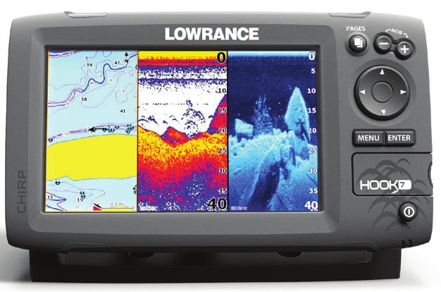
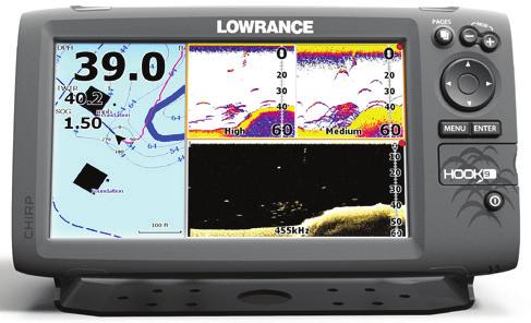
9 Combo pages Downscan page Downscan menu Two-panel page Three-panel page Press the PAGES key twice to switch active panels. The page menu for active page will be displayed when the MENU key is pressed. The active panel is denoted by an orange border. Sonar page Sonar menu Accessing the Settings menu x2 Chart page Chart menu 9 Basic Operation HOOK series

 or right (increase).")

10 Accessing menu items The keypad and ENTER key are used to select menu items and open submenus. Use the keypad to highlight the desired item and press ENTER. Working with menus There are several menu types used to make adjustments to options and settings, including scrollbars, on/off features and dropdown menus. Scrollbars Select the scrollbar and press the keypad left (decrease) or right (increase). Basic Operation HOOK series On/Off features Select an on/off menu item and press ENTER to turn it on/off. Dropdown menus Access the dropdown menu and press the keypad up/down to select the desired item and press ENTER. Dialogs NOTE: Press the MENU key to Exit menus. Dialogs are used for user input or for presenting information to the user. Depending on the type of entry, different methods are used to confirm, cancel or close the dialog. 10

 Fishing modes enhance the performance of your unit by providing preset packages of sonar settings geared")
11 Entering text Some functions, like naming a waypoint, route or trail, will require you to input text. To input text: 1. Use the keypad to select the desired character and press ENTER. 2. Repeat Step 1 for each character. 3. When entry is completed, highlight OK and press ENTER. Fishing modes (Conventional sonar only) Fishing modes enhance the performance of your unit by providing preset packages of sonar settings geared to specific fishing conditions. Switches letters to uppercase/ lowercase Switches keyboard between Alpha and QWERTY layout 11 Basic Operation HOOK series
12 Fishing mode options General Use 1000 ft or less Coastal Shallow Water 60 ft or less Shallow weedy bottoms Fresh Water 400 ft or less Inland/Near coastal Deep Water 1000 ft or more Offshore Slow Trolling Fast Trolling 400 ft or less Inland/Coastal 400 ft or less Inland/Coastal Clear Water 400 ft or less Inland/Coastal Brackish Water 400 ft or less Fresh-Saltwater mix Cursor The keypad moves the cursor around the display, allowing you to scroll the map, select map items and review sonar history. Press MENU and select Return to vessel or Exit cursor mode to clear the cursor. Goto cursor Used to navigate to the cursor. 1. Move the cursor to a desired location and press MENU. 2. Select Goto cursor and press ENTER. Ice 400 ft or less Ice fishing NOTE: Use Fresh Water mode when fishing in less than 100 feet of water; otherwise your unit may not track bottom properly. Basic Operation HOOK series 12
 Alarms (Enables arrival, off course and anchor alarm")
13 Advanced mode Enables advanced features and settings. The following features are enabled when Advanced mode is turned on: Navigation (Enables arrival radius, offcourse distance and Bearings setting) Alarms (Enables arrival, off course and anchor alarm options) NMEA 0183 Output (Requires optional Power/NMEA cable ) Units (Enables distance, speed, depth, temperature, and bearings options) Press the PWR/LIGHT key to access the Backlight dialog. NOTE: Leaving your unit in Standby mode when your boat is not in use will run down your battery. Restore defaults Resets unit options and settings to defaults. Standby mode Lowers power consumption by turning off sonar and the display. 13 Basic Operation HOOK series
14 Pages Direction to cursor Current Track Compass Surface Clutter Fish arches Your location Steer page The Steer page has a compass that shows your current track, the direction to your destination, and a digital data navigation panel. Pages HOOK series Navigation information 14 Bottom Sonar page Displays the water column moving from right to left on your unit s screen. Range Scale

15 Fish Surface clutter Depth contours Cursor Current location Structure Downscan page Range scale The Downscan page shows the water column moving from right to left. You can overlay downscan sonar on the conventional sonar page by selecting Downscan Overlay on the Sonar settings menu. Current cursor location; distance to cursor Waypoint Zoom Range Chart page Consists of map that moves in real-time as you move. By default, the map is shown from a birdseye view with North at the top of the screen. 15 Pages HOOK series

")


16 Combo pages This unit has four pre-configured combo pages. Chart/Sonar Sonar/Downscan Chart/Downscan Chart/Sonar/Downscan Customizing combo pages You can adjust the panel size of combo pages and control how the pages will be arranged on the screen: vertically (side) or horizontally (over). To make adjustments to combo page panels, select a combo page from the Pages carousel and press MENU. NOTE: To adjust panel size, access the customize menu after selecting a combo page for display and select Panel size. NOTE: Press the PAGES key twice to switch active panels. Pages HOOK series 16


17 Overlay data Used to select data shown on the Sonar, Structure and Chart pages. Overlay data Show Enables/disables the display of overlay data, allowing you to remove overlay data from the screen without deleting the current overlay data configuration. Configure Allows you to select/customize overlay data. To add overlay data: 1. From the Sonar, Chart or DownScan page, press MENU. 2. Select Overlay data and press ENTER. 3. Select Configure and press ENTER. 4. Press MENU and select Add. Press ENTER. 5. Select a data category and press ENTER. 6. Select the desired data and press ENTER. 7. Press MENU and select Return to Overlays. Press ENTER. 8. Press MENU, select Done Configuring and press ENTER. 17 Pages HOOK series

18 Sonar operation This unit supports two types of sonar: Conventional and Downscan. of the selected transducer type. This results in better image quality, better target separation and greater depth penetration. This unit supports High CHIRP, Medium CHIRP and Low CHIRP, depending on the transducer. CHIRP can be used with Lowrance conventional sonar transducers. 50/200 khz (Low/High CHIRP) 83/200 khz (Medium/High CHIRP) To use CHIRP, select the desired CHIRP frequency from the Frequency menu. The features described in this section are for conventional sonar. Refer to the Downscan section for information on Downscan features. CHIRP A CHIRP (Compressed High Intensity Radar Pulse) transducer transmits a modulated pulse of multiple frequencies within the bandwidth Sonar Operation HOOK series 18


 Sonar menu Press MENU from any sonar page")
19 Trackback You can review your recent sonar history by moving the cursor to the left until the screen starts to move in reverse. Blue sonar history bar Move the sonar history bar all the way to the right to resume normal sonar scrolling, or press MENU and select Exit cursor mode. Used to record sonar logs Sonar Menu (Advanced Mode) (Only active with Downscan overlay turned on) Sonar menu Press MENU from any sonar page to access the Sonar menu. 19 Sonar Operation HOOK series
20 New waypoint Places a waypoint at your current position or at the cursor position. From the new waypoint dialog, you can input a waypoint name, select an icon and input a desired latitude/longitude. Sensitivity Controls the level of detail shown on the display. Too much detail will clutter the screen. If Sensitivity is set too low, desired echoes may not be displayed. Colorline Helps distinguish fish or structure from the bottom by showing hard returns as light colors and soft returns as darker colors. A lower colorline setting will display only the hardest returns, shown in light colors. New waypoint menu Adjust Used to make adjustments to Sensitivity and Colorline. Auto sensitivity Keeps sensitivity at a level that works well under most conditions, reducing the needs for adjustments. Auto Sensitivity is turned on by default. Sonar Operation HOOK series 20

21 NOTE: You can make minor (+/-40%) changes to sensitivity with Auto Sensitivity turned on. You will have to turn it off to make significant adjustments. Range Selects the deepest range shown on the display. Range settings display the section of the water column from the water surface to the selected depth range. If you select too shallow a depth range, the unit will not be able to lock onto the bottom. Custom range Upper and Lower limits Used to select the upper limit and lower limit of a section of the water column. That allows you to view a section of the water column that does not include the water surface or the bottom. Upper and lower limits must be at least 6.5 ft (2 m) apart. Custom range menu NOTE: When using a custom range, you may not receive any digital depth readings, or you may receive incorrect depth information. Frequency Controls the transducer frequency used by the unit. This unit supports conventional, CHIRP and DownScan sonar frequencies. Only frequencies supported by your transducer will appear on the Frequency menu. 21 Sonar Operation HOOK series
22 50 khz 83 khz 200 khz Low CHIRP Medium CHIRP High CHIRP Sonar frequencies Best depth penetration with lower resolution Wider cone angle provides more bottom coverage and easy lure tracking Highest sensitivity and best target separation in shallow water Provides the best depth penetration with lower resolution images Better depth penetration than High CHIRP with minimal loss of target separation Better resolution in shallow water than Medium CHIRP Custom high Custom medium Selects a custom single frequency from within High or Low frequency ranges to help reduce/eliminate interference from other CHIRP transducers Ping speed Controls the rate the transducer uses to send sonar waves into the water. Ping speed adjustments can help reduce interference from other transducers. When using fishing modes, ping speed settings are optimized for the selected fishing conditions, so in most cases, adjustments are not necessary. Sonar Operation HOOK series 22


23 Sonar options Surface clarity Surface Clarity reduces surface clutter by decreasing the sensitivity of the receiver near the surface. Surface clutter Split zoom and Split flasher Switches the sonar display from full screen sonar to a split screen view. Noise rejection Uses advanced signal processing to monitor the effects noise (boat pumps, water conditions, engine ignition systems, etc.) has on your display, and then filters out undesired signals. Split zoom Split flasher Color Allows you to change the look of the display using palettes with varying degrees of color/brightness. 23 Sonar Operation HOOK series


24 Amplitude scope Displays the amplitude of the most recent echo. Amplitude scope Fish ID Displays fish echoes as fish symbols instead of fish arches. NOTE: Fish ID is not the most accurate method of fish detection since structure and suspended debris may be shown as a fish symbol on the display. Downscan options You can make adjustments to Downscan overlay settings from the sonar page. Downscan options are covered in more detail in the DSI section. Downscan options menu NOTE: The Downscan options menu will only be available when Downscan overlay is enabled. Stop sonar Prevents the transducer from transmitting to reduce/eliminate interference between two sonar units running on the boat at the same time. NOTE: Sonar history will not be recorded when sonar is stopped. Sonar Operation HOOK series 24


25 Logging sonar You can record sonar data and save the file on a microsd card inserted into the unit s card reader. Sonar settings Controls the quality of sonar logs. Higher quality logs will use more memory. Overlay data View previously saved sonar logs Allows you to select data to be displayed on top of the Sonar page. Overlay data setup is covered in the Pages section. Overlay data Conventional settings/downscan settings You can adjust settings for both Conventional sonar and Downscan sonar modes from the Sonar Settings menu. Only adjustments made to conventional sonar settings will be visible on the sonar page. 25 Sonar Operation HOOK series

26 Restricts unit s digital depth search capability Sonar settings menu Turns on/off Downscan overlay When the unit is in manual mode, you may not receive any depth readings, or you may receive incorrect depth information. Fishing mode Enhances the performance of your unit by providing preset packages of sonar settings geared to specific fishing conditions. For more information about fishing modes, refer to the Basic Operation section. Manual mode Restricts digital depth capability, so the unit will only send sonar signals to the selected depth range. That allows the display to continue smooth scrolling if the bottom depth is out of transducer range. Reset fishing mode Resets selected fishing mode to default settings. That is useful when you want to clear settings adjustments made while using a fishing mode. WARNING: Manual mode should only be used by advanced sonar users. Sonar Operation HOOK series 26
27 Installation Before setting keel offset, measure the distance from the transducer to the bottom of the motor - see illustration. If, for example, the distance is 1 foot, it will be input as (minus) 1 foot. Installation menu Keel offset All transducers measure water depth from the transducer to the bottom. As a result, water depth readings do not account for the distance from the transducer to the keel/bottom of motor or from the transducer to the water surface. Water speed calibration Calibrates a paddlewheel speed sensor with speed data from a GPS source. Temperature calibration Calibrates data from the transducer temperature sensor with data from a known temperature source to ensure the accuracy of temperature information. Reset water distance Reset Water Distance to zero. A: Keel offset (e.g. -1 foot) Transducer Transducer type Selects the type of transducer model attached to your unit. 27 Sonar Operation HOOK series


28 DownScan operation Features described in this section are for Down- Scan sonar. Refer to the Sonar operation section for information on conventional and CHIRP sonar. DownScan menu Press MENU from the DownScan page to view the DownScan menu. Trackback You can review your sonar history by pressing the keypad to the left until the screen starts to move in reverse and the sonar history bar appears at the bottom of the screen. DownScan history bar Move the sonar history bar all the way to the right to resume normal sonar scrolling, or press MENU and select Exit cursor mode. DownScan Operation HOOK series 28 Stops sonar transmission; pauses sonar scroll


29 New waypoint Places a waypoint at your current position or at the cursor position. From the new waypoint menu, you can input a waypoint name, select an icon and input a desired latitude/longitude. Contrast Adjusts the brightness ratio between light and dark areas on the screen, making it easier to distinguish suspended objects from the background. Contrast set to 40 Contrast set to 60 Contrast set to 80 New waypoint menu Adjust Accesses the Contrast adjustment scrollbar, allowing you to adjust contrast settings. Range Range settings display the section of the water column from the water surface to the selected depth range. NOTE: Auto range is the preferred setting for most fishing conditions. 29 DownScan Operation HOOK series


30 Custom range Upper and Lower limits Used to select the upper limit and lower limit of a section of the water column. That allows you to view a section of the water column that does not include the water surface. Frequency Controls the transducer frequency used by the unit. 800 khz offers the best resolution, while 455 khz has greater depth penetration. Ping speed Controls the rate the transducer uses to send sonar waves into the water. Ping speed adjustments can help reduce interference from other transducers. Upper and lower limits must be at least 6.5 ft (2 m) apart. Downscan options NOTE: When using a custom range, you may not receive any digital depth readings, or you may receive incorrect depth information. DownScan Operation HOOK series 30
 has on your display, and then filters out undesired signals. Surface clarity Surface Clarity reduces surface clutter by decreasing the sensitivity of the receiver near the surface.")

31 Noise rejection Uses advanced signal processing to monitor the effects noise (boat pumps, water conditions, engine ignition systems, etc.) has on your display, and then filters out undesired signals. Surface clarity Surface Clarity reduces surface clutter by decreasing the sensitivity of the receiver near the surface. Split zoom Changes the display to a split zoom view. Color Allows you to select a color palette best suited to your fishing conditions. The white background palette works well for suspended targets. Purple is useful for viewing structure detail and determining bottom hardness. Sepia is best for looking at bottom detail. Surface clarity set to Low. Surface clarity set to High. 31 DownScan Operation HOOK series
 will not be recorded when sonar is stopped. Overlay data Allows you to select data to be displayed on top of the DownScan page.")
32 Stop sonar Prevents the transducer from transmitting to reduce/eliminate interference between two sonar units running on the boat at the same time. NOTE: Sonar history (Trackback) will not be recorded when sonar is stopped. Overlay data Allows you to select data to be displayed on top of the DownScan page. Overlay data setup is covered in the Pages section. Overlay data Logging sonar You can record sonar data and save the file on a microsd card inserted into the unit s card reader. Settings Accesses the Settings menu. Refer to Sonar settings on page 25.. Controls the quality of sonar logs. Higher quality logs will use more memory. View previously saved sonar logs DownScan Operation HOOK series 32

33 Chart operation Chart menu Press MENU from any Chart pages to open the Chart menu. Chart menu New waypoint Creates a waypoint at your current location or at the cursor position. When the cursor is on the screen, waypoints will be saved at the cursor position; conversely, if the cursor is not displayed onscreen, waypoints will be saved at your current position. 33 Chart Operation HOOK series

34 Waypoints, Routes, Trails Used to create, edit, navigate and delete waypoints, routes and trails. Press the keypad left/right to toggle between waypoint, routes and trails tabs. Waypoints Screen Waypoints menu Waypoints menu Edit Allows you to edit the name, icon and latitude/longitude. of a selected waypoint. Chart Operation HOOK series 34


35 New Creates a new waypoint at the cursor or vessel position. You can also select waypoint name, icon and latitude/longitude from the new waypoint menu. Show Displays the selected waypoint on the map. Sort Controls how the waypoints list will be sorted by name or by nearest. Routes screen Used to create, edit, navigate and delete routes. Use the keypad to highlight the Routes tab to access the Routes screen. Goto Allows you to navigate to a waypoint. Delete and Delete All Delete is used to delete a selected waypoint. Delete All deletes all waypoints. Routes screen Routes menu Creating a route Routes can be created by inserting waypoints from the waypoints list or by using the cursor to position new points on the chart. You also can add waypoints to a route by selecting them from the chart screen. 35 Chart Operation HOOK series


36 Inserts waypoint between existing route waypoints Leg Name field Adds waypoint to end of the route Route waypoint menu To create a route from waypoint list: Starts navigation to the selected route waypoint 1. Press MENU from the Routes screen. 2. Select New... and press ENTER. 3. Press the keypad down to select the Leg Name field and press ENTER. 4.Press MENU, select Add to End and press ENTER. 5.Highlight Waypoint from list and press ENTER. 6. Select the desired waypoint and press ENTER twice. 7. Repeat point 6 to add more waypoints. 8. When the route is complete, press MENU, select Stop Adding and press ENTER. 9. Press MENU, select Stop Editing and press ENTER. 10. Select Save and press ENTER. Chart Operation HOOK series 36


37 Creating a route using points from chart: 1. Repeat Steps 1-4 from the instructions for Creating a route from waypoint list. 2.Select Point using chart and press ENTER. The chart page will appear. 3. Move the cursor to the desired location. Press ENTER to set a waypoint. 4. Repeat Step 3 to add more route waypoints. 5.Press MENU and select Stop Adding. Press ENTER. 6. Press MENU, select Stop Editing and press ENTER. 7.Highlight the Save button and press ENTER. 1. Select the desired route on the Route screen and press MENU. 2.Select Start and press ENTER. 3.Select Forward or Reverse and press ENTER. Navigating a route Routes can be navigated in forward or reverse. Routes menu 37 Chart Operation HOOK series


38 To cancel navigation: 1. Press MENU from the chart screen. 2.Select Navigation and press ENTER. 3.Highlight Cancel and press ENTER. 4.Select Yes and press ENTER. Edit and New Route menus Used to edit/create routes, route names and to turn on/off the route display. Turns on/off route display on map To edit/create a route, use the keypad to select the Route Leg Name field and press ENTER. To access the Edit or New Route menu, select Edit or New on the Routes menu and press ENTER. To finalize changes on the Edit or New Route menus, press MENU, highlight Stop editing and press ENTER. Select Done and press ENTER. Displayed Used to show/hide a route on the display, which prevents the screen from being cluttered by too many routes Delete and Delete All Delete is used to delete individual routes. Delete All, removes all routes. Chart Operation HOOK series 38


39 Trails screen Used to create, edit, navigate and delete trails. Use the keypad to highlight the Trails tab to access the Trails screen. Trails screen Trails menu Trails menu Creating trails When creating a trail you can customize the trail name and color from the New Trail. To create a trail: 1.Select New and press ENTER. The New Trail dialog will appear. 2. Select Save and press ENTER. 39 Chart Operation HOOK series


40 Edit and New Trail menus Allows you to edit/create trails, select trails names, trail color, trail display and the trail being recorded. You can also convert a trail into a route from the Edit Trail menu. Turns on/ off trail display on map Edit Trails menu Turns on/ off trail recording Navigating a trail A trail must be saved as a route before it can be navigated. To save a trail as a route: 1. Highlight the desired trail on the Trails screen and press ENTER. The Edit Trail menu will appear. 2.Highlight Create Route and press ENTER. The Edit Route menu will appear. 3.Highlight Done and press ENTER. 4. For navigation instructions refer to the Navigating a route segment. Displayed and Record Displayed allows you to show/hide trails on the map display, preventing the screen from being cluttered with trails. Chart Operation HOOK series 40
41 The Record command allows you to record, stop recording or resume recording a desired trail. Delete and Delete All Delete is used to remove individual trails. Delete All removes all trails. Orientation Allows you to select North Up or Course Over Ground (COG) as the map orientation. Overlay data Allows you to select data (course over ground, etc) to be displayed on top of the Chart page. Overlay data Overlay data setup is covered in the Pages section. Settings Accesses the Chart settings menu. 41 Chart Operation HOOK series


.")

42 Chart settings Controls map data used on the chart screen as well as display settings like grid lines, waypoints, routes and trails. COG extension A line extending from the front of the current position icon that estimates the time and distance to areas in front of you. Chart Settings menu Chart data Selects map data that will be used on the Chart display (Lowrance or Navionics regional map). Grid lines Displays base values for latitude and longitude, making it easier to get a general idea of your location on the latitude/longitude scale. Chart Operation HOOK series 42

43 Waypoints, Routes and Trail displays From the Chart Settings menu, you can turn on/ off waypoint, route and trail display properties. Turning off display properties allows you to get a better view of the map, if the screen becomes cluttered with waypoints, routes and/or trails. Navigation settings (Advanced mode only) Controls Arrival Radius and Off Course distance settings and is used to turn on/off WAAS/MSAS/ EGNOS. Waypoints, Routes, Trails Accesses the Waypoints, Routes & Trails screen. Waypoints, Routes and Trails are covered in the Chart section. Navigation Settings menu 43 Chart Operation HOOK series
44 Arrival radius Sets the arrival radius threshold for the Arrival alarm. The arrival alarm will sound when your vessel comes within a selected distance (arrival radius) of the destination waypoint. Off Course Distance Sets Off Course Distance threshold for the Off Course alarm. When the selected off course distance is exceeded, the Off Course alarm will sound when the alarm is enabled. Magnetic variation Controls whether magnetic variation will be calculated using Automatic or Manual settings. Magnetic variation is the angle between magnetic north and true north. The automatic setting reconciles the variation for you. WARNING: You should only use the Manual magnetic variation setting if you have variation information from a verified source. Bearings Controls whether bearing will be calculated using True North or Magnetic North. Magnetic North should be used when navigating with a compass course or heading; otherwise use the default setting, True North. Chart Operation HOOK series 44


45 AIS The marine Automatic Identification System (AIS) is a location and vessel information reporting system. It allows vessels equipped with AIS to automatically receive position, speed, course and vessel identity information from other AIS-equipped vessels. If an AIS device is connected, all targets detected by the device can be displayed. NOTE: Your unit must be set to Advanced mode to access NMEA 0183 settings (Requires optional Power/NMEA cable ) To select a Baud rate: 1. Access the settings menu. 2. Select NMEA 0183 and press ENTER. 3. Access the Baud rate dropdown menu on the NMEA 0183 settings dialog. 4. Select the same Baud rate used by your AIS device. 5. Select Save and press ENTER. AIS setup Before using AIS, your unit must be set to the same Baud rate as your AIS device. 45 AIS HOOK series
46 Target symbols The unit uses the AIS target symbols shown below: Symbol Stationary AIS target Description Moving AIS target with (COG) course extension line The extension line always represents the target s course over ground and is set to 10 minutes by default. When no signals have been received within a time limit, a target will be defined as lost. Lost AIS target The target symbol represents the last valid position of the target before the reception of data was lost. NOTE: If you receive heading data from an AIS vessel, the orientation of the vessel icon represents its heading. If heading data is not received, the orientation of the vessel icon represents its course over ground (COG). Filtering the targets All targets, by default, are shown on the display if an AIS device is connected to your unit. You can hide all targets, or filter the target icons based on distance and vessel speed. AIS HOOK series 46
 will be displayed.")

47 Viewing AIS target information When you place the cursor on an AIS icon, the MMSI number or vessel name (if available) will be displayed. You can view detailed information about a target by selecting the target and pressing ENTER. The AIS Vessel detail dialog will appear. 47 AIS HOOK series


 Displays software")
48 Settings Settings menu Accesses installation and configuration settings for your unit. System Adjusts unit settings like language, mute audio and advanced mode. System menu Refer to Advanced mode on page 13. Settings menu (Advanced mode only) Displays software information (Advanced mode only) Settings HOOK series 48


49 Set language Selects the language used on menus and dialogs. Audio Adjusts volume and turns on/off unit audio, like key beeps, alarm sounds, etc. Time Used to set local time, and time and date formats for your unit. Trip calculator Tracks trip time, speed and distance when you are moving faster than the selected threshold. Advanced mode Enables features and settings only available with unit in Advanced Mode. Restore defaults Switches the unit back to default settings. GPS Monitors the location of satellites in view and the quality of the unit s satellite lock-on. Browse files Allows you to view a list of the files saved to the microsd card. 49 Settings HOOK series
. You must view files on a computer or other microsd compatible device.")


50 Saving screenshots You can save screenshots to a microsd card by inserting a microsd card into the card slot and pressing Power and then Zoom (+). You must view files on a computer or other microsd compatible device. Alarms Enables alarms and selects alarm thresholds. Arrival, Off Course and Anchor alarms are only available in Advanced mode. NOTE: You cannot save screenshots to internal memory, Navionics cards, or other mapping cards. About Displays software information about this unit. Before attempting a software update, you can check the version of software your unit is using by accessing the About screen. Lowrance periodically updates unit software to add features and improve functionality. Alarms menu Sounds alarm when Fish ID symbol appears on display Settings HOOK series 50
 sounds alarm when vessel moves a selected distance (Advanced Mode only) sounds alarm when vessel enters water")
 You can select the NMEA 0183 sentences the unit will use when connected to a VHF radio or other NMEA 0183 device.")

51 Arrival Off Course Anchor Shallow Fish Alarms sounds alarm when you are within a selected distance of your destination (Advanced Mode only) sounds alarm when course exceeds a selected off-course threshold (Advanced Mode only) sounds alarm when vessel moves a selected distance (Advanced Mode only) sounds alarm when vessel enters water shallower than the selected shallow threshold sounds alarm when a fish symbol (Fish ID) appears on the sonar screen NMEA 0183 Output (Requires optional Power/NMEA cable ) You can select the NMEA 0183 sentences the unit will use when connected to a VHF radio or other NMEA 0183 device. You can also adjust the Baud rate, but the default setting works best under most conditions. Units Allows you to select the unit of measure used by the unit. Unit options vary depending on whether the unit is in basic or advanced mode. Simulator Simulates GPS and/or sonar activity. Simulations can be customized on the Simulator options menu. Basic Mode Advanced Mode 51 Settings HOOK series
52 Case size Display Waterproof standard Backlight Communications HOOK -4 General 6.6 H (168 mm) x 3.8 W (96 mm); 7.5 H (189 mm) with bracket (4.3 diagonal) 16-bit color TFT LCD IPX7 Regulatory mark 0980 Power Transmit power 500 W RMS Power requirement 12 V Voltage input 10 to 17 V Current drain Typical: 1.1 A Fuse type LED (11 levels) NMEA 0183 Input/Output (optional Power/NMEA cable ) 3-amp Automotive Max depth Max speed Available transducer frequencies Transducer cable 20 ft (6 m) Mapping card slot GPS Antenna Mapping compatibility Waypoints, Routes & Trails Sonar 300 ft (91 m) 455/800 khz 1000 ft (305 m) 83/200 khz 2500 ft (762 m) 50/200 khz 70 mph HDI 50/200 khz (Low/High CHIRP) HDI 83/200 khz (Medium/High CHIRP 83/200 khz (Medium/High CHIRP) GPS microsd and microsdhc 16 parallel channel (internal) Lake Insight and Nautic Insight PRO, Navionics +, C-MAP MAX-N, Fishing Hot Spots PRO, & Insight Genesis. Up to 3000 waypoints, 100 routes/100 waypoints per route, 100 retraceable plot trails/up to 10,000 points per trail Specifications HOOK series 52
53 Case size Display Waterproof standard Backlight Communications HOOK -5 General 5.4 H (136 mm) x 6.9 W (174 mm); 5.9 H (151 mm) with bracket (5 diagonal) 16-bit color Full color VGA Solar MAX Plus TFT IPX7 Regulatory mark 0980 Power Transmit power 500 W RMS Power requirement 12 V Voltage input 10 to 17 V Current drain Typical: 1.1 A Fuse type LED (11 levels) NMEA 0183 Input/Output (optional Power/NMEA cable ) 3-amp Automotive Max depth Max speed Available transducer frequencies Transducer cable 20 ft (6 m) Mapping card slot GPS Antenna Mapping compatibility Waypoints, Routes & Trails Sonar 300 ft (91 m) 455/800 khz 1000 ft (305 m) 83/200 khz 2500 ft (762 m) 50/200 khz 70 mph HDI 50/200 khz (Low/High CHIRP) HDI 83/200 khz (Medium/High CHIRP 83/200 khz (Medium/High CHIRP) GPS microsd and microsdhc 16 parallel channel (internal) Lake Insight and Nautic Insight PRO, Navionics +, C-MAP MAX-N, Fishing Hot Spots PRO, & Insight Genesis. Up to 3000 waypoints, 100 routes/100 waypoints per route, 100 retraceable plot trails/up to 10,000 points per trail 53 Specifications HOOK series
54 Case size Display Waterproof standard Backlight Communications HOOK-7 General 5.3 H (234mm) x 9.2 W (136mm); 5.9 H (151mm) with bracket (7 diagonal) 16-bit color Full VGA Solar MAX 800x480 color TFT IPX7 Regulatory mark 0191 Power Transmit power 500 W RMS Power requirement 12 V Voltage input 10 to 17 V Current drain Typical: 1.1 A Fuse type LED (11 levels) NMEA 0183 Input/Output (optional Power/NMEA cable ) 3-amp Automotive Max depth Max speed Available transducer frequencies Transducer cable 20 ft (6 m) Mapping card slot GPS Antenna Mapping compatibility Waypoints, Routes & Trails Sonar 300 ft (91 m) 455/800 khz 1000 ft (305 m) 83/200 khz 2500 ft (762 m) 50/200 khz 70 mph HDI 50/200 khz (Low/High CHIRP) HDI 83/200 khz (Medium/High CHIRP 83/200 khz (Medium/High CHIRP) GPS microsd and microsdhc 16 parallel channel (internal) Lake Insight and Nautic Insight PRO, Navionics +, C-MAP MAX-N, Fishing Hot Spots PRO, & Insight Genesis. Up to 3000 waypoints, 100 routes/100 waypoints per route, 100 retraceable plot trails/up to 10,000 points per trail Specifications HOOK series 54
55 Case size Display Waterproof standard Backlight Communications HOOK-9 General 6.16 H (157 mm) x W (281 mm); 6.2 H (156.5 mm) with bracket (9 diagonal) 16-bit color Full color VGA Solar MAX Plus TFT IPX7 Regulatory mark 0980 Power Transmit power 500 W RMS Power requirement 12 V Voltage input 10 to 17 V Current drain Typical: 1.1 A Fuse type LED (11 levels) NMEA 0183 Input/Output (optional Power/NMEA cable ) 3-amp Automotive Max depth Max speed Available transducer frequencies Transducer cable 20 ft (6 m) Sonar 300 ft (91 m) 455/800 khz 1000 ft (305 m) 83/200 khz 3000 ft (914 m) 50/200 khz 70mph HDI 50/200 khz (Low/High CHIRP) HDI 83/200 khz (Medium/High CHIRP 83/200 khz (Medium/High CHIRP) GPS Mapping card slot microsd and microsdhc GPS Antenna 16 parallel channel (internal) Lake Insight and Nautic Insight PRO, Navionics +, C-MAP MAX-N, Fishing Mapping Hot Spots PRO, & Insight Genesis. compatibility Waypoints, Routes & Trails Up to 3000 waypoints, 100 routes/100 waypoints per route, 100 retraceable plot trails/up to 10,000 points per trail 55 Specifications HOOK series
56 Index A About 50 Adjust menu 20 Advanced Mode 13 AIS 45 Filtering targets 46 Target symbols 46 Vessel detail dialog 47 Alarms 50 Amplitude Scope 24 Anchor alarm 51 Arrival alarm 51 Arrival Radius 44 Auto Sensitivity 20 B Bearings 44 Browse Files 49 C Cancel navigation 38 Chart 42 Chart Data 42 Chart menu 42 Chart Page 15 CHIRP 18 COG Extension 42 Color 23, 31 Colorline 20 Contrast 29 Creating a route 35 Creating trails 39 Cursor 12 Custom Range 21, 30 D Data Port 49 Depth Range 29 Dialogs 10 Dropdown menus 10 DSI menu 28 E Editing waypoints 34 F Fish alarm 51 Fish ID 24 Fishing Mode 11 Fishing Modes Reset 26 Frequency 21, 30 G Goto cursor 12 Goto waypoint 35 GPS Source 49 GPS Status 49 Grid Lines 42 H High CHIRP 22 I Ice Mode 24 Installation menu 27 K Keel Offset 27 L Language 49 Low CHIRP 22 Index HOOK series 56
57 M O S T Magnetic Variation 44 Man Overboard waypoint 6 Man Overboard waypoint 6 Manual Mode 26 Medium CHIRP 22 microsd cards 7 Mute Audio 49 N Navigating a route 37 Navigating a trail 40 Navigation 43 Navigation menu 43 New Waypoint 33 NMEA Noise Rejection 23, 31 Off Course alarm 51 Off Course Distance 44 On/Off features 10 Orientation 41 Overlay Data 17, 32, 41 Configure 17 Show 17 P Page menus 8 Page selection 8 Ping Speed 22 R Range 29 Reset Fishing Mode 26 Reset water distance 27 Route display 43 Routes Screen 35 Saving Screenshots 50 Scrollbars 10 Sensitivity 20 Setup wizard 8 Shallow alarm 51 Software Updates 50 Sonar Installation 27 Sonar Menu 18 Sonar Options menu 23 Sonar Page 14 Sonar settings 25 Sort waypoints 35 Split Flasher 23 Split Zoom 23 Standby mode 13 Steer Page 14 Stop Sonar 24, 32 Surface Clarity, 23 System settings 48 Temperature calibration 27 Text entry 11 Time 49 Trackback 28 Trail display 43 Trails Screen 39 Turn unit on/off 6 U Unit Controls 6 Units 51 Upper and Lower Limits 21, 30 W Waypoint display 43 Waypoints, Routes, Trails 34 Working with menus Index HOOK series
HOOK-X Series. Operation manual ENGLISH. HOOK-4x HOOK-5x HOOK-7x
 HOOK-X Series Operation manual ENGLISH HOOK-4x HOOK-5x HOOK-7x Lowrance and Navico are registered trademarks of Navico. Navico may find it necessary to change or end our policies, regulations and special
Elite-4x, Elite-5x, Elite-7x & Elite-9x
 Elite-4x, Elite-5x, Elite-7x & Elite-9x Installation & Operation manual Operation manual Copyright 2014 Navico All rights reserved. Lowrance and Navico are registered trademarks of Navico. Navico may find
Mark-4, Elite-4, Elite-5, Elite-7 & Elite-9
 Mark-4, Elite-4, Elite-5, Elite-7 & Elite-9 Installation & Operation Operation manual manual Copyright 2014 Navico All rights reserved. Lowrance and Navico are registered trademarks of Navico. Fishing
Elite-4m HD. Installation & Operation. manual Operation manual
 Elite-4m HD Installation & Operation manual Operation manual Copyright 2014 Navico All rights reserved. Lowrance and Navico are registered trademarks of Navico. Fishing Hot Spots is a registered trademark
Elite 5X DSI, Mark 5X DSI, Elite 4X DSI & Mark 4X DSI
 Elite 5X DSI, Mark 5X DSI, Elite 4X DSI & Mark 4X DSI Installation & Operation Operation manual manual Copyright 2011 Navico All rights reserved. Lowrance and Navico are registered trademarks of Navico.
Installation & Operation manual Operation manual
 Elite-3x Installation & Operation manual Operation manual Copyright 2014 Navico All rights reserved. Lowrance and Navico are registered trademarks of Navico. Navico may find it necessary to change or end
Elite 5 DSI, Elite 4 DSI & Mark 4 DSI
 Elite 5 DSI, Elite 4 DSI & Mark 4 DSI Installation & Operation Operation manual manual DSI COMBO COVER_.indd 1 9/13/2011 9:40:26 PM Copyright 2011 Navico All rights reserved. Lowrance and Navico are registered
Elite 5 DSI Operation manual
 Elite 5 DSI Operation manual Copyright 2010 Navico All rights reserved. No part of this manual may be copied, reproduced, republished, transmitted or distributed for any purpose, without prior written
Hook2 Series. Operator Manual. 5 HDI, 5 TS, 7X GPS TS, 7 HDI, 7 TS, 9 TS, 9 HDI, and 12 TS ENGLISH
 Hook2 Series Operator Manual 5 HDI, 5 TS, 7X GPS TS, 7 HDI, 7 TS, 9 TS, 9 HDI, and 12 TS ENGLISH www.lowrance.com Preface Disclaimer As Navico is continuously improving this product, we retain the right
B. HDS-5m & HDS-7m. GPS Mapping Receiver. Operations Guide
 988-0176-02B HDS-5m & HDS-7m GPS Mapping Receiver Operations Guide Software updates for your unit. Occassionally check the Lowrance website for free software upgrades for your unit. Go to www.lowrance.com
Hook2 X Series. Operator Manual. 4x GPS, 4x Sonar, 5x GPS HDI, 7x GPS HDI ENGLISH
 Hook2 X Series Operator Manual 4x GPS, 4x Sonar, 5x GPS HDI, 7x GPS HDI ENGLISH www.lowrance.com Preface Disclaimer As Navico is continuously improving this product, we retain the right to make changes
HDS Gen2 Touch. Operator manual. lowrance.com ENGLISH
 HDS Gen2 Touch Operator manual ENGLISH lowrance.com Copyright 2012 Navico All Rights Reserved Lowrance and Navico are registered trademarks of Navico. Fishing Hot Spots is a registered trademark of Fishing
HDS Gen3 Quick Start Guide
 HDS Gen3 Quick Start Guide EN Overview 1 4 6 5 7 2 3 8 9 10 11 No. Key Function 1 Touchscreen 2 Pages key Activates the home page 3 Cursor keys Pans the cursor, moves through menu items and adjusts values
Vulcan. Getting Started ENGLISH. bandg.com
 Vulcan Getting Started ENGLISH bandg.com Vulcan Getting Started 3 4 Vulcan Getting Started Contents 9 Introduction 9 The Home page 10 Application pages 11 Integration of 3 rd party devices 12 GoFree wireless
STRIKER PLUS 4/5/7/9. Owner s Manual
 STRIKER PLUS 4/5/7/9 Owner s Manual 2017 Garmin Ltd. or its subsidiaries All rights reserved. Under the copyright laws, this manual may not be copied, in whole or in part, without the written consent of
HDS Gen2 Touch Chartplotter Operator manual
 HDS Gen2 Touch Chartplotter Operator manual ENGLISH lowrance.com Copyright 2013 Navico All Rights Reserved Lowrance and Navico are registered trademarks of Navico. Fishing Hot Spots is a registered trademark
HDS Live Quick Guide. Keys. Press to activate the home page Repeat short presses to cycle the favorite buttons Press to open the new waypoint dialog
 HDS Live Quick Guide EN Keys Pages Press to activate the home page Repeat short presses to cycle the favorite buttons Press to open the new waypoint dialog B Waypoint Press twice to save a waypoint Press
GO XSE. Getting Started. simrad-yachting.com ENGLISH
 GO XSE Getting Started ENGLISH simrad-yachting.com Contents 7 Introduction 7 The Home page 8 Application pages 10 Basic operation 10 System Controls dialog 10 Turning the system on and off 11 Selecting
IS35 Color Display. User Manual ENGLISH. simrad-yachting.com
 IS35 Color Display User Manual ENGLISH simrad-yachting.com Preface Navico is continuously improving this product, therefore we retain the right to make changes to the product at any time which may not
NSS evo3 Quick Start Guide
 NSS evo3 Quick Start Guide EN Front panel 2 3 4 5 6 7 8 9 10 11 12 12 1 No. Description 1 Touch screen. Pages/Home key - press to open the Home page for page selection and setup 2 options. WheelKey - user
HDS Gen2 RTM 2.0, 2.5 & 3.0 addendum
 HDS Gen2 RTM 2.0, 2.5 & 3.0 addendum This addendum documents new features included in the HDS Gen2 2.0, 2.5 and 3.0 software updates. These features are not described in the HDS Gen2 Operation manual.
Boating Tip #45: Chartplotters
 Boating Tip #45: Chartplotters As navigation technology has advanced, hand held GPS receivers have further evolved into chartplotters. Chartplotters graphically display a vessel s position, heading and
Quick Guide. Keys. Card reader. System controls dialog C D. A Pages Press to activate the home page Press to zoom the image Zoom in/ B
 Keys ELITE Ti 2 Quick Guide EN C D Pages Press to activate the home page Press to zoom the image Zoom in/ Simultaneous press both keys to save a Man out Overboard (MO) waypoint at the current vessel position
GN70/MX610/MX612 QuickStart Guide
 GN70/MX610/MX612 QuickStart Guide EN The front panel 1 2 3 PAGE MENU 8 10 POS NAV 9 HDG AIS 11 4 5 6 ESC MOB 7 ENT USB 12 13 USB No. Description 1 PAGE key: Brings up different screen page every time this
CL7 DISPLAY QUICK START MANUAL 6YD-2819U-E0
 CL7 DISPLAY QUICK START MANUAL 6YD-2819U-E0 Introduction WARNING See the Important Safety and Product Information guide in the product box for product warnings and other important information. Device Overview
HELIX SERIES. Operations Summary Guide
 HELIX_Operations_Summary_Guide_532403-3EN_C.qxp_Layout 1 8/30/18 10:01 AM Page A HELIX SERIES Operations Summary Guide SAFETY INFORMATION! You must read the Important Information about your Humminbird
HELIX 9, HELIX 10, and HELIX 12. Operations Guide EN_A
 HELIX 9, HELIX 10, and HELIX 12 Operations Guide 532400-2EN_A THANK YOU! Thank you for choosing Humminbird, the #1 name in marine electronics. Humminbird has built its reputation by designing and manufacturing
Manual. Network Expansion Port 2 NEP-2. English. Brands by Navico - Leader in Marine Electronics
 Manual Network Expansion Port 2 NEP-2 English www.lowrance.com www.simrad-yachting.com Brands by Navico - Leader in Marine Electronics Disclaimer As Navico is continuously improving this product, we retain
GO XSE. Getting Started. ENGLISH
 GO XSE Getting Started ENGLISH www.simrad-yachting.com Contents 6 Introduction 6 The Home page 7 Application pages 9 Basic operation 9 System Controls dialog 9 Turning the system on and off 10 Selecting
GO XSE Quick Guide. Front panel. The System controls dialog. No. Key Function
 GO XSE Quick Guide EN Front panel 1 No. Key Function 1 Power Press and hold to turn the unit ON/OFF. Press once to display the System control dialog. The System controls dialog Used for quick access to
AIS. HELIX Accessory Guide TABLE OF CONTENTS. Overview... 5 Track AIS Targets... 5 AIS Target Overview... 7 Turn on Alarms... 8
 AIS HELIX Accessory Guide 532440-1_A TABLE OF CONTENTS Overview............................................. 5 Track AIS Targets...................................... 5 AIS Target Overview...................................
HELIX 5 AND HELIX 7. G2 Series Operations Manual EN_A
 HELIX 5 AND HELIX 7 G2 Series Operations Manual 532509-1EN_A THANK YOU! Thank you for choosing Humminbird, the #1 name in marine electronics. Humminbird has built its reputation by designing and manufacturing
Handheld GPS Connection Kit _D
 Handheld GPS Connection Kit 531324-1_D Thank You! Thank you for choosing Humminbird, America s #1 name in fishfinders. Humminbird has built its reputation by designing and manufacturing top-quality, thoroughly
Operation Manual. Simrad NSE8 and NSE12 Multi-function Displays. English. A brand by Navico - Leader in Marine Electronics.
 Operation Manual Simrad NSE8 and NSE12 Multi-function Displays English www.simrad-yachting.com A brand by Navico - Leader in Marine Electronics Preface Disclaimer As Navico is continuously improving this
MEDALLION INSTRUMENTATION SYSTEMS MasterCraft Viper system
 MEDALLION INSTRUMENTATION SYSTEMS 2010 MasterCraft Viper system MEDALLION INSTRUMENTATION SYSTEMS VIPER CHART PLOTTING OPERATORS MANUAL MAP SCREEN This manual will attempt to familiarize the
HOOK2 Quick Guide. 5 HDI, 5 TS, 7x GPS TS, 7 HDI, 7 TS, 9 HDI, 9 TS and 12 TS models. Front controls
 HOOK Quick Guide 5 HDI, 5 TS, 7x GPS TS, 7 HDI, 7 TS, 9 HDI, 9 TS and 1 TS models Front controls EN 1 3 4 5 6 7 1 Pages Press to activate the Home page. Press to zoom the image. Zoom in/ Press both keys
Chart Plotter USER MANUAL
 Chart Plotter USER MANUAL 1. Disclaimer and warnings 5 2. Introduction 6 2.1 Keyboard 6 2.2 Connections scheme 7 3. Getting started 10 3.1 Switching ON 10 3.2 Switching OFF 10 3.3 First Setup page 10
CL7 DISPLAY QUICK START MANUAL 6YD-F819U-E0
 CL7 DISPLAY QUICK START MANUAL 6YD-F819U-E0 Introduction WARNING See the Important Safety and Product Information guide in the product box for product warnings and other important information. Device Overview
HDS Gen2 RTM 3.5 software update
 HDS Gen2 RTM 3.5 software update The HDS RTM 3.5 software update enables autopilot control of the MotorGuide Xi5 trolling motor via the Lowrance SmartSteer interface. MotorGuide Xi5 trolling motor To use
HDS Carbon Operator Manual
 HDS Carbon Operator Manual ENGLISH www.lowrance.com Preface Disclaimer As Navico is continuously improving this product, we retain the right to make changes to the product at any time which may not be
NSO evo2 QuickStart Guide
 NSO evo2 QuickStart Guide EN Turning the NSO evo2 system on and off Press the Power key/button: - on the front of the NSO evo2 Processor - on the front of the monitor (depending on type of monitor and
GO7. Operator Manual ENGLISH. simrad-yachting.com
 GO7 Operator Manual ENGLISH simrad-yachting.com Preface Disclaimer As Navico is continuously improving this product, we retain the right to make changes to the product at any time which may not be reflected
365i Combo Operations Manual _A
 365i Combo Operations Manual 531728-1_A Thank You! Thank you for choosing Humminbird, America s #1 name in fishfinders. Humminbird has built its reputation by designing and manufacturing top-quality, thoroughly
Installation Guide Solar Power Bluetooth Hands-free Car Kit GBHFK231
 Installation Guide Solar Power Bluetooth Hands-free Car Kit 1 GBHFK231 Table of Contents Package Content 4 Requirements 5 Device Overview 6 Charging Your Car Kit 7 Recommended Way of Using Your Car Kit
Handheld GPS Connection Kit _A
 Handheld GPS Connection Kit 531324-2_A Thank You! Thank you for choosing Humminbird, the #1 name in marine electronics. Humminbird has built its reputation by designing and manufacturing top-quality, thoroughly
II. Features. A. Battery Door B. Battery Lock C. Chain Slot D. Sounder E. LCD display screen F. Read Key G. Right Key H. Left Key I.
 Contents I. Pager Layout...1 II. Features... 2 III. Guide to Operation...5 1. Power On/Off...5 1.1 Power On...5 1.2 Power Off...5 2. Private Messages......6 2.1 Read Private Messages...6 2.2 Protect Private
Moomba Boats PV480 Color Display
 Moomba Boats PV480 Color Display 2018 Owner s Manual 1715055 2017-08-30 We continually strive to bring you the highest quality, full-featured products. As a result, you may find that your actual display
GO XSE Quick Start Guide
 GO XSE Quick Start Guide EN Front panel 1 No. Key Function 1 Power Press once to display the System control dialog. Press and hold to turn the unit ON/OFF. The System controls dialog Used for quick access
f200 English User Manual Contents
 f200 English User Manual Contents About this Guide...3 FCC Statement...3 WEEE Notice...3 CE Regulatory Notice...4 Notes on Installation...4 Caution...4 1 Introduction...5 1.1 Features...5 1.2 Package Contents...5
USB Hub-Audio Series. January 1999 A
 Series January 1999 A15-0157-110 FCC COMPLIANCE STATEMENT: This device complies with part 15 of the FCC Rules. Operation is subject to the following two conditions: (1) This device may not cause harmful
Manufacture:Shenzhen Roverstar Technology Co.,Ltd Dash camera/dvr D28RS
 1 USER MANUAL Introduction Dear Customer! Thank you for purchasing this NAVITEL product. NAVITEL R1000 is a multifunctional high-definition DVR with many functions and features that are described in this
Vulcan. Operator Manual ENGLISH. bandg.com
 Vulcan Operator Manual ENGLISH bandg.com Preface Disclaimer As Navico is continuously improving this product, we retain the right to make changes to the product at any time which may not be reflected
LCX-17M Fish-finding Sonar & Mapping GPS
 Pub. 988-0151-291 www.lowrance.com This GPS model is available as a simulator download from this CD or from the Lowrance web site. To download from the CD select download, follow the prompts and it will
Content. 1 Welcome Your phone Phone overview Functions of Keys Getting started... 6
 User Manual -1- Content 1 Welcome... 3 2 Your phone... 4 2.1 Phone overview... 4 2.2 Functions of Keys... 5 3 Getting started... 6 3.1 Installing the SIM Cards and the Battery... 6 3.2 Linking to the Network...
Magellan Triton. User Manual. Magellan Triton 200 Magellan Triton 300 Magellan Triton 400 Magellan Triton 500
 Magellan Triton User Manual Magellan Triton 200 Magellan Triton 300 Magellan Triton 400 Magellan Triton 500 Magellan Navigation, Inc. 960 Overland Court, San Dimas, CA 91773 IMPORTANT SAFETY WARNINGS The
Chapter 2: Installation. ST80 Multiview. Operation & Setup
 Distributed by Any reference to Raytheon or RTN in this manual should be interpreted as Raymarine. The names Raytheon and RTN are owned by the Raytheon Company. Chapter 2: Installation 1 ST80 Multiview
Streaming Smart Stick. Quick Start Guide
 Streaming Smart Stick Quick Start Guide GETTING STARTED 1.1 Inside the Box 1 1.2 Equiso Streaming Smart Stick 2 1.3 Equiso Remote 3 1.4 Using Your Equiso Remote 4 1.5 What You Need 5 1.6 Charging the Remote
This user manual has been specially designed to guide you through the functions and features of your device.
 DL102 Cautions This user manual has been specially designed to guide you through the functions and features of your device. 1) Please read this manual carefully before using your device to ensure safe
768 Combo Operations Manual
 768 Combo Operations Manual 531683-1_C Section Title Thank You! Thank you for choosing Humminbird, America's #1 name in fishfinders. Humminbird has built its reputation by designing and manufacturing topquality,
Labtec Wireless Optical Desktop. Getting Started Guide
 Labtec Wireless Optical Desktop Getting Started Guide Important Ergonomic Information Long periods of repetitive motions using an improperly set-up workspace, incorrect body position, and poor work habits
Contents Using the 4SK909 Twister
 Contents About this manual... 1 Notices for use... 1 Know the product... 2 Using the 4SK909 Twister... 3 Charging... 3 Inserting the TF memory card... 4 Powering ON/OFF the Dash Cam... 4 Installing in-vehicle
MEDALLION INSTRUMENTATION SYSTEMS VIPER CHART PLOTTING OPERATORS MANUAL
 MEDALLION INSTRUMENTATION SYSTEMS VIPER CHART PLOTTING OPERATORS MANUAL TABLE OF CONTENTS Map Screen... 3 Squash Pad... 4 Navigation Menu Map View... 5 Orient View... 6 Select Course... 7 Creating a New
GPS Receiver and GPS Receiver/Heading Sensor
 GPS Receiver and GPS Receiver/Heading Sensor Thank You! Thank you for choosing Humminbird, the #1 name in Fishfinders. Humminbird has built its reputation by designing and manufacturing topquality, thoroughly
PTSGOB8W. Quick Start Guide
 PTSGOB8W Quick Start Guide Introduction Thank you for your choosing the new Tablet PC. This guide serves to enable users to get to know and familiar with our product as soon as possible. Here we have made
GPS Receiver and GPS Receiver/Heading Sensor _E
 GPS Receiver and GPS Receiver/Heading Sensor 531478-4_E Thank You! Thank you for choosing Humminbird, the #1 name in marine electronics. Humminbird has built its reputation by designing and manufacturing
WMC Remote Control and Receiver RRC-127 User Manual
 Welcome Congratulations on your purchase of the Remote Control and Receiver for Windows Media Center. The infrared (IR) remote control and receiver let you access and manage your Media Center PC and other
GR4 GPS Receiver Accessory Manual B. offered by Busse-Yachtshop.de
 GR4 GPS Receiver Accessory Manual 531248-1-B Thank You! Thank you for choosing Humminbird, America's #1 name in fishfinders. Humminbird has built its reputation by designing and manufacturing top-quality,
7 Inch Quad Core Tablet
 7 Inch Quad Core Tablet Cautions This user manual has been specially designed to guide you through the functions and features of your device. ) Please read this manual carefully before using your device
NSS evo3 Quick Start Guide
 NSS evo3 Quick Start Guide EN Front panel 2 3 4 5 6 7 8 9 10 11 12 12 1 No. Description 1 Touch screen. Pages/Home key - press to open the Home page for page selection and setup 2 options. WheelKey - user
NSS evo2. Operator Manual ENGLISH
 NSS evo2 Operator Manual ENGLISH Preface Disclaimer As Navico is continuously improving this product, we retain the right to make changes to the product at any time which may not be reflected in this version
SmartStrike Map Card. HELIX Accessory Manual EN_A
 SmartStrike Map Card HELIX Accessory Manual 532476-1EN_A THANK YOU! Thank you for choosing Humminbird, the #1 name in marine electronics. Humminbird has built its reputation by designing and manufacturing
IMPORTANT SAFETY WARNINGS
 IMPORTANT SAFETY WARNINGS The Magellan explorist GC receiver is a navigation aid designed to assist you in arriving at your selected destination. When using the Magellan explorist GC receiver, these safety
User s Manual BeamPod User Manual
 User s Manual BeamPod General Safety Information 1. Keep the device and packaging materials out of reach of infants and children. 2. Keep the power adapter and other contacts from water, Dry your hands
IS40 PRO. Operator Manual ENGLISH
 IS40 PRO Operator Manual ENGLISH Preface Disclaimer As Navico is continuously improving this product, we retain the right to make changes to the product at any time which may not be reflected in this
Please review this guide fully before use. For any questions not answered in this guide, please contact WARNING Battery warning
 Please review this guide fully before use. For any questions not answered in this guide, please contact Support@Komando.com WARNING THIS DEVICE SHOULD NOT BE ADJUSTED BY THE DRIVER WHILE DRIVING. Battery
Anker Portable Bluetooth Speaker. Instruction Manual. Specifications. Model No: A7908
 Anker Portable Bluetooth Speaker Model No: A7908 Instruction Manual Package Contents Anker Portable Bluetooth Speaker Micro USB cable 3.5mm audio cable Travel pouch Instruction manual Product Features
Matrix 67 GPS Chartplotter Operations Manual
 Matrix 67 GPS Chartplotter Operations Manual 531296-1_C Thank You! Thank you for choosing Humminbird, America's #1 name in fishfinders. Humminbird has built its reputation by designing and manufacturing
GETTING STARTED. Link Controller. Remote
 GETTING STARTED i-pilot Link Controller Software Updates Link Controller 1. Loading the software file onto the SD card. Note that no other software loads (FF or remote) can be on the card. 2. Prep the
Safety and Maintenance You can use your Tablet PC under a wide range of environmental conditions. However, to ensure long use and continued high
 EVG7 DL46 Getting Started Congratulations on your purchase of a Tablet PC. The Tablet PC is a fully functional PC with built-in LAN, and wireless connectivity. With your Tablet PC you will be able to organize
use. Best of all, the is affordable and will keep you in touch with those important to you.
 Congratulations on your purchase of our Pager. By incorporating some of the most advanced electronic paging technologies, the is reliable and easy to use. Best of all, the is affordable and will keep you
KS-PD100. INTERFACE ADAPTER for ipod R
 INTERFACE ADAPTER for ipod R KS-PD100 Thank you for purchasing a JVC product. Please read this manual carefully before operation, to ensure your complete understanding and to obtain the best possible performance
Installation Instructions
 Alliance Arming Station AL-1111, AL-1116 1048520C September 2006 Copyright 2006, GE Security Inc. Introduction This is the GE Alliance Arming Station for models AL-1111 (four-line LCD) and AL-1116 (four-line
Operation Manual for Cloud 3700F Version 0
 Operation Manual for Cloud 3700F Version 0 Version: 0 Page 1 of 5 Document History Version Date Description of Change Author 0.0 06 May 2014 Initial version Sarav Version: 0 Page 2 of 5 Table of Contents
Ethernet Networking Installation & Operations Manual HUMMINBIRD ETHERNET
 Ethernet Networking Installation & Operations Manual 531906-1EN_A GPS Unit 1 HUMMINBIRD ETHERNET Unit 2 Thank You! Thank you for choosing Humminbird, America's #1 name in Fishfinders. Humminbird has built
Radio Mini Wireless Wheel Mouse User s Guide MODEL: RFMSW-15
 Radio Mini Wireless Wheel Mouse User s Guide MODEL: RFMSW-15 Trademark Recognition Windows, Office 97 and MS-IntelliMouse are registered trademarks of Microsoft Corp. RFMSW-15 THIS DEVICE COMPLIES WITH
Tank II User s Manual
 Tank II User s Manual -1- Table of Contents Key Functions... 4 Getting Started... 5 Installing the SIM Card, SD Card and Battery... 5 Menu Guide... 7 Messaging... 7 Contact... 7 Audio player... 8 Call
User's Guide. Video Borescope Inspection Camera. Model BR70
 User's Guide Video Borescope Inspection Camera Model BR70 Introduction Congratulations on your purchase of this Extech BR70 Video Borescope. This instrument was designed for use as a remote inspection
IS42J. Operator Manual. ENGLISH
 IS42J Operator Manual ENGLISH www.simrad-yachting.com Preface Disclaimer As Navico is continuously improving this product, we retain the right to make changes to the product at any time which may not
Chicony Standard Bluetooth Keyboard Users Manual. Model No.: KT-1063
 Chicony Standard Bluetooth Keyboard Users Manual Model No.: KT-1063 Issue: Jan. 03, 2011 Scope Getting Start Thank you for choosing this ultrathin keyboard with Bluetooth technology to ensure no hinder
MULTI FUNCTION DISPLAY MFD8/MFD12
 MULTI FUNCTION DISPLAY MFD8/MFD12 User's Handbook The purpose of this guide is to provide the basic operation for this equipment. For more detailed information, see the Operator's manual. All brand and
OWNER'S GUIDE BT 390
 OWNER'S GUIDE BT 390 WIRELESS HEADPHONES Thank you for purchasing PHIATON BT 390. - Please follow the directions, and read the guidelines carefully before use. Please keep the owner s guide for future
REMOTE CONTROL USER MANUAL QUICK CONNECT MINI-SPLIT
 COMFORT...BUILT TO LAST QUICK CONNECT MINI-SPLIT REMOTE CONTROL USER MANUAL FOR THE REMOTE CONTROL INCLUDED WITH YOUR PERFECT AIRE MINI-SPLIT AIR CONDITIONER Before using the remote control with your air
ADVANCED REMOTE CONTROL
 ADVANCED REMOTE CONTROL (SUITS IP28) INSTALLATION & OPERATING INSTRUCTIONS 918-962 12/07/10 The Advanced Remote Control is tested safe when installed in accordance with this installation manual. It is
RS2 X 2 With you on the front line
 RS2 X 2 With you on the front line Quick Start and User Manual V 1.4.0 REVEALMEDIA.COM RVL800-000016 Quick start Quick start 1 Charge 1 Charge 2 Charge the camera for four hours or until the charging light
GPSMAP 78 series. quick start manual. for use with the GPSMAP 78, GPSMAP 78s, and GPSMAP 78sc
 GPSMAP 78 series quick start manual for use with the GPSMAP 78, GPSMAP 78s, and GPSMAP 78sc Getting Started warning See the Important Safety and Product Information guide in the product box for product
FCC NOTICE: FCC STATEMENT:
 FCC NOTICE: This equipment has been tested and found to comply with the limits for a Class B digital device, pursuant to Part 15 of the FCC Rules. These limits are designed to provide reasonable protection
BTK-A21 Bluetooth Headset User Manual
 BTK-A21 Bluetooth Headset User Manual Thank you for purchasing the Mini Bluetooth Headset BTK-A21, we hope you will be delighted with its operation. Please read this user's guide to get started, and to
DVI KVM Switch user manual Model
 DVI KVM Switch user manual Model 156066 INT-156066-UM-0808-01 introduction Thank you for purchasing the INTELLINET NETWORK SOLUTIONS DVI KVM Switch, Model 156066. This convenient device lets you control
SLIMLINE DASH CAM Audio & Video Recorder
 SLIMLINE DASH CAM Audio & Video Recorder 1 EK142CAM INSTRUCTION MANUAL PLEASE READ ALL INSTRUCTIONS CAREFULLY AND RETAIN FOR FUTURE USE Getting Started Remove the Car Digital Video Recorder from the box.
Deluxe In/Out Remote Thermometer with Trend Chart
 Deluxe In/Out Remote Thermometer with Trend Chart MODEL: JTR-168LR USER'S MANUAL INTRODUCTION Congratulations on your purchase of the JTR-168LR Deluxe In/ Out Remote Thermometer. The basic package comes