Handheld GPS Connection Kit _D
|
|
|
- Hugh Simon
- 5 years ago
- Views:
Transcription

1 Handheld GPS Connection Kit _D
2 Thank You! Thank you for choosing Humminbird, America s #1 name in fishfinders. Humminbird has built its reputation by designing and manufacturing top-quality, thoroughly reliable marine equipment. Genuine Humminbird accessories offer the opportunity to upgrade and expand the capabilities of your Humminbird product. Your Humminbird is designed for trouble-free use in even the harshest marine environment. In the unlikely event that your Humminbird does require repairs, we offer an exclusive Service Policy - free of charge during the first year after purchase, and available at a reasonable rate after the one-year period. For complete details, see the Warranty section included in this manual. We encourage you to read this manual carefully in order to get full benefit from your Humminbird accessory. WARNING! This device should not be used as a navigational aid to prevent collision, grounding, boat damage, or personal injury. When the boat is moving, water depth may change too quickly to allow time for you to react. Always operate the boat at very slow speeds if you suspect shallow water or submerged objects. WARNING! Disassembly and repair of this electronic unit should only be performed by authorized service personnel. Any modification of the serial number or attempt to repair the original equipment or accessories by unauthorized individuals will void the warranty. Handling and/or opening this unit may result in exposure to lead, in the form of solder. WARNING! This product contains lead, a chemical known to the state of California to cause cancer, birth defects and other reproductive harm. NOTE: Some features discussed in this manual require a separate purchase, and some features are only available on international models. Every effort has been made to clearly identify those features. Please read the manual carefully in order to understand the full capabilities of your model. NOTE: Illustrations in this manual may not look the same as your product, but your unit will function in the same way. i
3 Table of Contents How GPS Works 1 Connecting a Handheld Receiver to the Fishing System 2 Handheld GPS Connection Kit 3 Direct-connect Cable Installation (AS HHGAR082, AS HHMAG344)... 3 Bare Wire Cable Installation (AS-HHGPS)...4 Views 7 Combo View... 7 Track View... 8 Bird s Eye View View Orientation Introduction to Navigation 12 Waypoints, Routes and Tracks Save, Edit or Delete a Waypoint Navigate to a Waypoint or Position Add a Waypoint Target or Trolling Grid Save or Clear a Current Track Edit, Delete or Hide Saved Tracks The Menu System 17 Start-Up Options Menu 19 Normal Operation Simulator System Status PC Connect (with PC Connect Cable Only) Sonar X-Press Menu (Sonar Views Only) 23 Mark Navigation X-Press Menu 24 Waypoint 001 (Only with an Active Cursor on a Waypoint) Cursor to Waypoint (Track or Combo View Only) Zoom Go To Save Current Track Clear Current Track Skip Next Waypoint (Only When Navigating) Cancel Navigation (Only When Navigating) Remove Target (Only If Target is Active) Remove Grid (Only If Grid is Active) ii
4 Table of Contents Sonar Window (Combo View Only) Waypoint [Name] (Most Recently-Created Waypoint) Navigation Menu Tab 30 Current Track Saved Tracks Waypoints View Orientation North Reference Grid Rotation Trackpoint Interval Track Min Distance (Advanced) Map Datum (Advanced) Course Projection Line Delete All Nav Data (Advanced) Continuous Navigation Mode Alarms Menu Tab 37 Off Course Alarm Arrival Alarm Drift Alarm Setup Menu Tab 39 Units - Distance Units - Speed Triplog Reset Local Time Zone (Advanced) Daylight Saving Time (Advanced) Position Format (Advanced) Time Format (Advanced, International Only) Date Format (Advanced, International Only) NMEA Output (Advanced) Accessories Menu Tab 44 Troubleshooting 45 Fishing System Doesn t Power Up Fishing System Defaults to Simulator with a Transducer Attached Display Problems Finding the Cause of Noise iii
5 Table of Contents Fishing System Accessories 48 1-Year Limited Warranty 50 iv
 is a satellite navigation system designed and maintained by the U.S. Department of Defense.")
6 How GPS Works Your Fishing System uses GPS and sonar to determine your position, display it on a grid, and provide detailed underwater information. The Global Positioning System (GPS) is a satellite navigation system designed and maintained by the U.S. Department of Defense. GPS was originally intended for military use; however, civilians may also take advantage of its highly accurate position capabilities, typically within +/- 10 meters, depending on conditions. This means that 95% of the time, the GPS receiver will read a location within 10 meters of your actual position. Some GPS Receivers also use information from WAAS (the Wide Area Augmentation System), EGNOS (the European Geostationary Navigation Overlay Service), and MSAS (the MTSAT Satellite Augmentation System) satellites if they are available in your area. GPS uses a constellation of satellites that continually send radio signals to the earth. Your present position is determined by receiving signals from satellites and measuring the distance from the satellites. All satellites broadcast a uniquely coded signal once per second at exactly the same time. The GPS receiver on your boat receives signals from satellites that are visible to it. Based on time differences between each received signal, the GPS receiver determines its distance to each satellite. With distances known, the GPS receiver mathematically triangulates its own position. With once per second updates, the GPS receiver then calculates its velocity and bearing. The following GPS functionality is currently supported by the Fishing System when it is connected to a GPS receiver: View current position View current track (breadcrumb trail) View precision speed and heading from your GPS receiver Save tracks and waypoints Travel a route and navigate from one waypoint to the next. 1
7 Connecting a Handheld GPS Receiver to the Fishing System Humminbird has designed two different direct-connect cables to fit the most common GPS Receiver configurations. In case neither of the two direct-connect cables fit your configuration, we also provide a cable that can connect your Handheld GPS Receiver to your Fishing System control head via an additional NMEA data cable which you must purchase from your Handheld GPS Receiver manufacturer. The Humminbird cable part numbers that are compatible with your Handheld GPS Receiver are shown in the chart below. Your Handheld GPS Our Cable Part # Your Handheld GPS Our Cable Part # Garmin GPS V AS HHGAR082 GPS III AS HHGAR082 GPS 12XL AS HHGAR082 GPS III Pilot AS HHGAR082 GPSMAP 60 AS HHGAR082 GPS III Plus AS HHGAR082 GPSMAP 60Cx AS HHGAR082 Magellan Meridian AS HHMAG344 GPSMAP 60CSx AS HHGAR082 Sport Trak AS HHMAG344 GPS 72 AS HHGAR082 Garmin etrex AS-HHGPS* GPS 76 AS HHGAR082 etrex Summit AS-HHGPS* GPS 76S AS HHGAR082 etrex Legend AS-HHGPS* GPSMAP 76 AS HHGAR082 etrex Venture AS-HHGPS* GPSMAP 76Cx AS HHGAR082 etrex Vista AS-HHGPS* GPSMAP 76CSx AS HHGAR082 etrex Camo AS-HHGPS* GPS 92 AS HHGAR082 Geko 201 AS-HHGPS* GPS II AS HHGAR082 Geko 301 AS-HHGPS* GPS II Plus AS HHGAR082 Other GPS Handhelds* AS-HHGPS* *NOTE: The AS-HHGPS accessory requires the purchase of an additional NMEA data cable (made by the manufacturer of the Handheld GPS Receiver) to complete the connection to the Handheld GPS Receiver. 2
8 Handheld GPS Connection Kit The Humminbird Handheld GPS Connection Kit includes the following items: Handheld GPS Cable (NMEA data connection and optional 12 VDC power connection) Y-cable for multiple accessory attachment (NMEA and ACCY connections) Handheld GPS Connection Kit Accessory Manual NOTE: You may have purchased either a direct-connect NMEA data cable, or one that requires splicing to an additional NMEA data cable (made by the manufacturer of the Handheld GPS receiver) to complete the connection to the Handheld GPS receiver. NOTE: The AS-HHGPS accessory requires the purchase of an additional NMEA data cable (made by the manufacturer of the Handheld GPS Receiver) to complete the connection to the Handheld GPS Receiver. Direct-connect Cable Installation (AS HHGAR082, AS HHMAG344) Use the following instructions to direct-connect your Handheld GPS Receiver to your Fishing System. 1. Insert the Handheld GPS Cable s NMEA-COM connector into the appropriate terminal slot on the back of your Fishing System control head. The slots are keyed to prevent reverse installation, so be careful not to force the connector into the holder. NOTE: If the terminal slot is already used by another accessory, you will need to replace it with the included Y-cable. After you ve inserted the Y-cable s COM-connector into the appropriate terminal slot on the back of your Fishing System control head, connect the Handheld GPS Cable to the NMEA-COM connector, and attach your accessory cable to the ACCY-COM connector. 2. Connect the Handheld GPS Cable to your Handheld GPS Receiver. Refer to your Handheld GPS Receiver manufacturer s user manual for instructions. 3
9 3. Your NMEA Cable allows you to connect your Handheld GPS Receiver to an external 12 VDC power supply. If you choose to run your Handheld GPS Receiver from an external 12 VDC power supply, connect the black wire to ground (-) and the red wire to positive (+) 12 VDC power. CAUTION: Use caution before connecting the red +12V wire to your Handheld GPS Receiver, and consult your Handheld GPS Receiver manufacturer s user manual before connecting power and ground. Some Handheld GPS Receivers have a different voltage input than 12V. 4. Power up the Fishing System Control Head (see your Fishing System Operations Manual for details). NOTE: The Fishing System accepts NMEA 0183 version 2.20 input at 4800 baud and listens for the NMEA sentences RMC and GGA to determine current position, heading, speed, time and date. In addition, the GSA and GSV sentences are used to monitor GPS satellite location and usage. 5. If the NMEA output of your Handheld GPS Receiver can be configured, confirm the following settings on your GPS Handheld Receiver: NMEA Output = enabled Baud rate = 4800 RMS and GGA sentences = enabled NOTE: See your the Handheld GPS Receiver manufacturer s user manual for NMEA output information. NOTE: When the Fishing System detects the NMEA-input from the Handheld GPS Receiver, the Combo, Track and Bird s Eye Views will be added automatically to the VIEW key function. A Navigation Menu tab and the Navigation X-Press TM Menu will also be added automatically to the menu system. Bare Wire Cable Installation (AS-HHGPS) Use the following instructions to connect your Handheld GPS to your fishing system using the AS-HHGPS. You will need to purchase the NMEA data cable (not included) from the manufacturer of your Handheld GPS Receiver. 1. Insert the Handheld GPS Cable s NMEA-COM connector into the appropriate terminal slot on the back of your Fishing System control head. The slots are keyed to prevent reverse installation, so be careful not to force the connector into the holder. The pinouts of the Humminbird NMEA data cable are as follows: Red Wire: +12V Black Wire: Ground Green Wire: NMEA In White Wire: NMEA Out. 4
10 NOTE: If the terminal slot is already used by another accessory, you will need to replace it with the included Y-cable. After you ve inserted the Y-cable s COM-connector into the appropriate terminal slot on the back of your Fishing System control head, connect the Handheld GPS Cable to the NMEA-COM connector, and attach your accessory cable to the ACCY-COM connector. 2. Connect the NMEA In (Green wire) of the cable to the NMEA Out of your Handheld GPS Receiver. CAUTION! Use caution before connecting the red +12V wire to your Handheld GPS Receiver, and consult your Handheld GPS Receiver manufacturer s user manual before connecting power and ground, as some Handheld GPS Receivers have a different voltage input than 12V. The Fishing System control head can provide a maximum of 100mA to a Handheld GPS Receiver. The voltage provided is typically 1 volt lower than the boat battery voltage supplied to the Fishing System control head. NOTE: The white NMEA Out wire is provided for other uses, such as connecting to an autopilot, but it is not needed to connect to a Handheld GPS Receiver. 3. Connect the Handheld GPS Cable to your Handheld GPS Receiver. Refer to your Handheld GPS Receiver manufacturer s user manual for instructions. 4. Your NMEA Cable allows you to connect your Handheld GPS Receiver to an external 12 VDC power supply. If you choose to run your Handheld GPS Receiver from an external 12 VDC power supply, connect the black wire to ground (-) and the red wire to positive (+) 12 VDC power. CAUTION: Use caution before connecting the red +12V wire to your Handheld GPS Receiver, and consult your Handheld GPS Receiver manufacturer s user manual before connecting power and ground. Some Handheld GPS Receivers have a different voltage input than 12V. 5
11 5. Power up the Fishing System Control Head (see your Fishing System Operations Manual for details). NOTE: The Fishing System accepts NMEA 0183 version 2.20 input at 4800 baud and listens for the NMEA sentences RMC and GGA to determine current position, heading, speed, time and date. In addition, the GSA and GSV sentences are used to monitor GPS satellite location and usage. 6. If the NMEA output of your Handheld GPS Receiver can be configured, confirm the following settings on your GPS Handheld Receiver: NMEA Output = enabled Baud rate = 4800 RMS and GGA sentences = enabled NOTE: See your the Handheld GPS Receiver manufacturer s user manual for NMEA output information. NOTE: When the Fishing System detects the NMEA-input from the Handheld GPS Receiver, the Combo, Track and Bird s Eye Views will be added automatically to the VIEW key function. A Navigation Menu tab and the Navigation X-Press TM Menu will also be added automatically to the menu system. 6

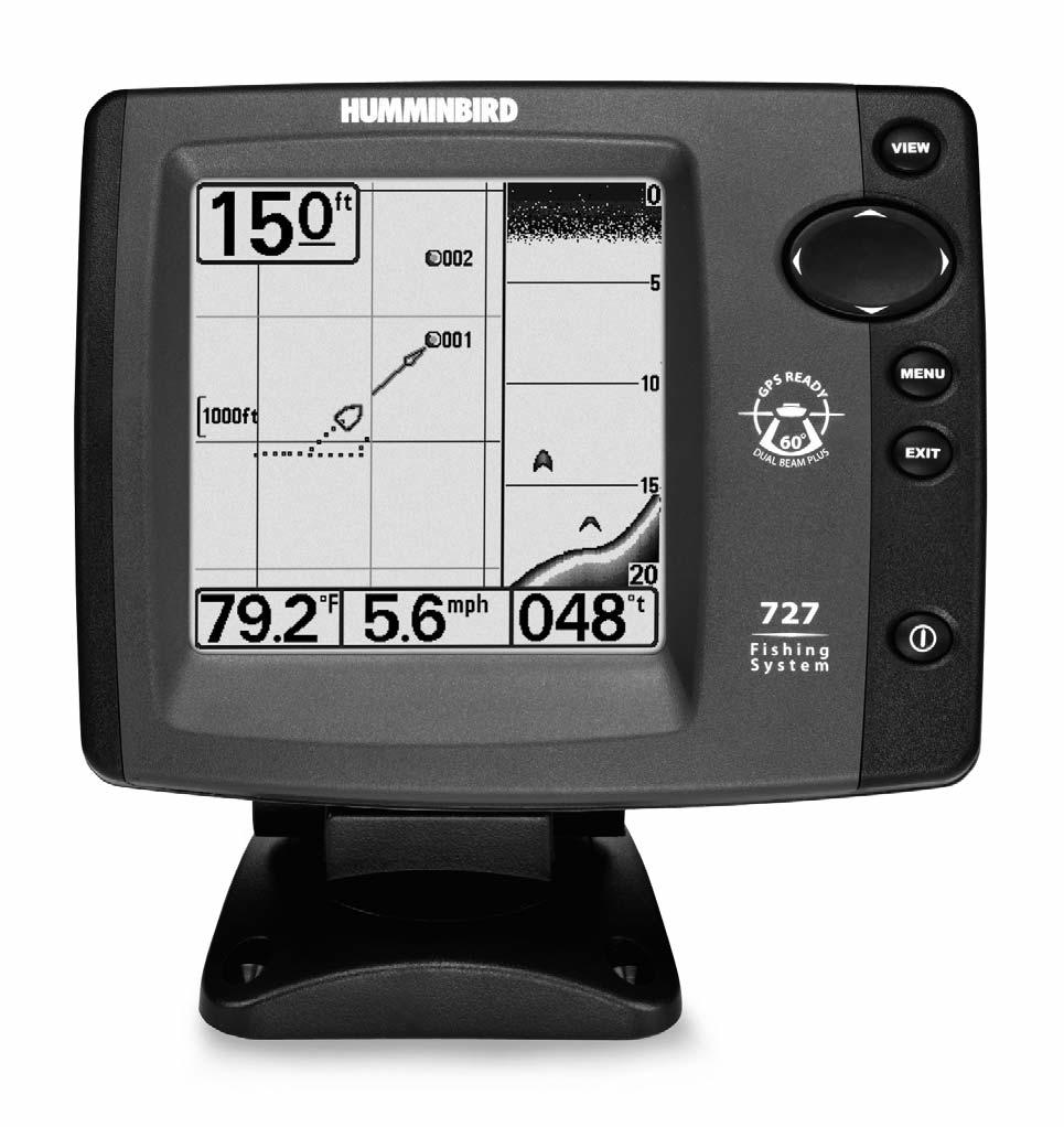
12 Sonar Views Views The following views will be added to the view rotation when a Handheld GPS Receiver is connected to the Fishing System: Bird's Eye View Track View Combo View Navigation views: Combo View Track View Bird s Eye View. When the VIEW key is pressed, the display cycles through the available views. When the EXIT key is pressed, the display cycles through the available views in reverse order. Any view can be hidden or displayed as part of the view rotation using the Views Menu tab. Combo View Combo View is displayed as a split screen, with Track View on the left and Sonar View on the right side of the screen. The width of the sonar window can be changed by pressing the MENU key and using the 4- WAY Cursor Control key to select Sonar Window from the Sonar X-Press Menu. Depth Combo View Sonar Window Track Scale Water Surface Temperature Speed of Boat Bearing of Boat with Respect to True North 7
 showing where the boat has been, along with saved tracks, waypoints, and the current route (when navigating).")
13 Combo View with Navigation Depth Sonar Window Track Scale Water Surface Temperature Speed of Boat Bearing of Boat with Respect to True North Track View Track View displays the current track (also known as the position history or breadcrumb trail) showing where the boat has been, along with saved tracks, waypoints, and the current route (when navigating). Depth Track View Track Scale Water Surface Temperature Speed of Boat Bearing of Boat with Respect to True North 8
14 Track View with Navigation Depth Track Scale XTE: Cross Track Error. Distance of Boat from Route DTG: Distance to Go to Waypoint Water Surface Temperature Speed of Boat BRG: Bearing to Waypoint Bearing of Boat with Respect to True North Track View with Active Cursor Depth Track Scale Latitude and Longitude Position of Cursor Distance to Go To Cursor Bearing to Cursor Active Cursor Bearing of Boat with Respect to True North Panning: Use the 4-WAY Cursor Control key to move the track around on the display in the direction of the key being pressed. When you do this, a bull s eye cursor is drawn at the center of the screen and is linked to the boat by a gray line, even if the boat is off the screen. At the same time, the distance and bearing from the boat to the cursor position, as well as the 9
15 latitude/longitude coordinates of the cursor, are displayed at the bottom of the view. Pressing the EXIT key moves the cursor back to the original position of the boat. Bird s Eye View Bird s Eye View shows a 3D perspective view of the track from a point above and behind the boat (the eye point). As the boat turns, the eye point moves to follow the boat. When you press the 4-WAY Cursor Control key in the Bird s Eye View, the position of the eye point will shift. This allows you to move and turn the eye point so that you can look off to the sides, or even behind the boat. Pressing the RIGHT or LEFT arrow keys on the 4-WAY Cursor Control key turns the eye point right or left, while pressing the UP arrow key moves the eye point forward, and pressing the DOWN Cursor key moves the eye point backward. Pressing the EXIT key moves the eye point back to its original position behind and above the boat. Bird s Eye View Depth Latitude and Longitude Position of Boat Speed of Boat Boat Icon Water Surface Temperature Bearing of Boat with Respect to True North 10
16 Bird s Eye View with Navigation Depth Latitude and Longitude Position of Boat XTE: Cross Track Error. Distance of Boat from Route DTG: Distance to Go to Waypoint Water Surface Temperature Speed of Boat Boat Icon BRG: Bearing to Waypoint Bearing of Boat with Respect to True North View Orientation When your Fishing System control head is in Track or Combo View, you can choose the orientation of the view by selecting North-Up or Course-Up on the Navigation Main Menu. When North-Up orientation is selected, True North is shown at the top of the display. In other words, objects located to the north of the boat are drawn above the boat. When Course-Up orientation is selected, the direction of motion of the boat is shown at the top of the display. In other words, objects ahead of the boat are drawn above the boat. In both orientations, the view pans automatically, so that the boat is always centered on the display. NOTE: When the boat is stationary, it is drawn as a circle. When the boat is in motion, it takes on a boat shape, pointed in the direction of motion (always Up in the Course-Up orientation). 11
17 Introduction to Navigation Use your Fishing System to establish waypoints at areas of interest and navigate to those waypoints via a route (representing the shortest intended distance between waypoints). You can also view and save tracks, which represent the actual path of the boat. Waypoints, Routes and Tracks Waypoints are stored positions that allow you to mark areas of interest or navigation points. Waypoints, Routes and Tracks Depth Waypoint Route XTE: Cross Track Error. Distance of Boat from Route DTG: Distance to Go to Waypoint Water Surface Temperature Speed of Boat Track BRG: Bearing to Waypoint Bearing of Boat with Respect to True North Routes link two or more waypoints together to create a path for navigation, and are used in trip planning. A route represents your intended navigation and shows the shortest path from each waypoint to the next. As you travel a route, staying on the route line is the most efficient way to get to your destination, although you should always look out for obstacles not shown on the fishing system view. Tracks consist of detailed position history, and are displayed as a breadcrumb trail of trackpoints. The Current Track shows the position history since the unit was powered up. You can clear the Current Track or save it at any time. The current track represents your actual path so far. 12
18 Save, Edit, or Delete a Waypoint Save your current position as a waypoint: On any view, press the MENU key to display the X- Press TM Menu. Select Mark and press the RIGHT Cursor key to save the current position of the boat as a waypoint. Save the cursor position as a waypoint: On the Track or Combo View, use the 4-WAY Cursor Control key to designate the position you want to save as a waypoint. Then press the MENU key to display the X-Press TM Menu. Select Mark and press the RIGHT Cursor key to save the current position of the boat as a waypoint. Save a position from the sonar history: On any Sonar View, use the 4-WAY Cursor Control key to point to a feature in the sonar history (also called the Sonar Saver feature). Then press the MENU key to display the X-Press TM Menu. Select Mark and press the RIGHT Cursor key to create a waypoint at the location where that sonar reading was taken. The new waypoint will also record the depth at that location. NOTE: When you save a waypoint by any of these methods, a numerical waypoint name is automatically assigned. You can edit the waypoint information later to give it a different name and select an icon to represent it (see Navigation Menu Tab, Waypoint Submenu). Display the Waypoints Submenu: From any view, press the MENU key twice to display the Main Menu System, then use the RIGHT Cursor key to select the Navigation tab. Select Waypoints and press the RIGHT Cursor key to display the Waypoints submenu. Program a specific position as a waypoint: To create a Waypoints Submenu waypoint that is NOT your current position, from the Waypoints submenu, select the Create option and press the RIGHT Cursor key. Use the 4-WAY Cursor Control key to program a waypoint name, latitude, longitude, and icon before selecting Save. Edit a waypoint: From the Waypoints submenu, select Edit and press the RIGHT Cursor key to display a list of saved waypoints. Select the waypoint you want to edit and press the RIGHT Cursor key. Use the 4-WAY Cursor Control key to move from field to field, and the UP and DOWN Cursor keys to changes values once you are in a field. In the Waypoint Name, Latitude and Longitude fields, use the UP and DOWN Cursor keys to change the letter or number. All upper and lower case letters are available, as well as digits 0-9 and some punctuation characters. In the Waypoint Icon field, use the UP and DOWN Cursor keys to change the icon used to represent the waypoint on the Combo and Track Views. You can exit these fields with the LEFT and RIGHT Cursor keys or by pressing the EXIT key. Select Save and press the RIGHT Cursor key to save your changes. 13
19 To make it easier to view a waypoint to edit, select Sort By and press the LEFT or RIGHT Cursor keys to select a sort order: Name shows the waypoints alphabetically Time shows the most recently-created waypoint first Distance shows the closest waypoint first. Delete a waypoint: From the Waypoints submenu, select Delete and press the RIGHT Cursor key to display a list of waypoints. Select the waypoint you want to delete, then press the RIGHT Cursor key. You will be asked to confirm deletion before the waypoint is actually deleted. Navigate to a Waypoint or Position Navigate to the cursor position: From the Track or Combo View, use the 4-WAY Cursor Control key to select a position or waypoint to which you want to navigate. Press the MENU key once to display the Navigation X-Press TM Menu. Select Go To and press the RIGHT Cursor key. Navigation will begin immediately. Navigate to a specified waypoint: Press the MENU key once to display the Navigation X-Press TM Menu. Select Go To and press the RIGHT Cursor key. Then choose the waypoint to which you would like to navigate from the waypoint list and press the RIGHT Cursor key to select it. NOTE: By repeating the previous instructions, you can add more waypoints to create a longer multisegment route. Skipping a waypoint: From the Navigation X-Press TM Menu, select Skip Next Waypoint and press the RIGHT Cursor key. If there is not another waypoint to skip to, navigation will be cancelled. Cancel navigation: From the Navigation X-Press TM Menu, select Cancel Navigation and press the RIGHT Cursor key. Canceling navigation removes the route and any waypoints created. 14


20 Add a Waypoint Target or Trolling Grid Waypoint Target Track Scale Track View with Target Add or Remove a Waypoint Target: From the Waypoints submenu, select Target and press the RIGHT Cursor key to display a list of waypoints. Select the waypoint you want to target. A target consisting of concentric circles centered on the selected waypoint will appear on all of the navigation views; the target shows various distance ranges from the targeted waypoint. To remove the target, choose Remove Target from the Navigation X-Press Menu, and press the RIGHT Cursor key. Track Scale Waypoint Trolling Grid Track View with Grid Add or Remove a Trolling Grid: From the Waypoints submenu, select Grid and press the RIGHT Cursor key to display a list of waypoints. Select the waypoint to which you want to add the grid. The trolling grid will appear on all of the navigation views and can be used as a guide when trolling around a waypoint. The grid can be rotated to any desired heading using Grid Rotation from the Navigation main menu. To remove the trolling grid, choose Remove Grid from the Navigation X-Press Menu, and press the RIGHT Cursor key. NOTE: Only one waypoint can have either a target or a grid at one time. If you apply a target or a grid to a new waypoint, the original waypoint will lose its target or grid. NOTE: The spacing of the rings on the waypoint target and the spacing of the grid lines on the trolling grid is the same as the length of the scale bar on the left edge of the display. Zooming in or out will decrease or increase the spacing, respectively. 15
21 Save or Clear a Current Track Save the current track: From the Navigation X-Press TM Menu, select Save Current Track and press the RIGHT Cursor key. The track will remain on the display, but will change from black to gray. To remove the track completely from the display, see Edit, Delete or Hide Saved Tracks. NOTE: When you save a track, a name is automatically assigned. The track name consists of a date/time stamp but can be re-named later (see Edit a Saved Track). Clear the current track: From the Navigation X-Press TM Menu, select Clear Current Track and press the RIGHT Cursor key. The track will be removed from the display and discarded. Edit, Delete or Hide Saved Tracks Display the Tracks Submenu: From any view, press the MENU key twice to display the Main Menu System, then use the RIGHT Cursor key to select the Navigation tab. Select Saved Tracks and press the RIGHT Cursor key to display the Saved Tracks submenu. Edit a saved track: From the Saved Tracks submenu, select Edit and press the RIGHT Cursor key to display the list of saved tracks. Select the track you want to edit and press the RIGHT Cursor key. When the Edit Track dialog box appears, use the 4-WAY Cursor Control key to move between fields. In the Track Name field, the UP and DOWN Cursor keys change the letter or number. All upper and lower case letters are available, as well as digits 0-9 and some punctuation characters. You can exit the Track Name field with the LEFT and RIGHT Cursor keys or by pressing the EXIT key. Select Save and press the RIGHT Cursor key to save your changes. Delete a saved track: From the Saved Tracks submenu, select Delete and press the RIGHT Cursor key to display the list of saved tracks. Select the track you want to delete and press the RIGHT Cursor key. You will be asked to confirm deletion before the track is actually deleted. Hide or display a saved track: From the Saved Tracks submenu, select Edit and press the RIGHT cursor key to display the list of saved tracks. Select the track you want to hide or display, and press the RIGHT Cursor key. When the Edit Track dialog box appears, use the LEFT and RIGHT Cursor keys to change the Visibility field to Hidden or Visible. Press the EXIT key to return to the Tracks submenu. 16


22 The Menu System The menu system is divided into easy-to-use menu modules. The main components of the menu system are as follows: Start-Up Options Menu - Press the MENU key during the power up sequence to view the Start-Up Options menu. X-Press TM Menu - The X-Press TM Menu allows you to access the frequently-used settings without having to navigate through the whole menu system. Press the MENU key once to display the X-Press Menu. When you select a menu item from the X-Press Menu, the menu will collapse, leaving only the menu choice on the screen. Use the UP or DOWN Cursor keys to reactivate the X-Press Menu. X-Press TM Menu NOTE: The X-Press Menu choices will vary depending on which view is active when you press the MENU key, as well as whether you are in Normal or Advanced User Mode. Either the Sonar or Navigation X-Press Menu will appear, depending on the view you are in. Main Menu Tabs - Less frequently-adjusted menus are grouped into the Main Menu System. The Main Menu System is organized under the following tab headings to help you find a specific menu item quickly: Alarms, Sonar, Navigation (if the GPS Receiver is attached), Setup, Views, and Accessories. Press the MENU key twice for the Main Menu, then use the RIGHT or LEFT Cursor keys to select a tab, and use the DOWN or UP Cursor keys to select a specific menu item under that tab, then use the LEFT or RIGHT Cursor keys again to change a menu setting. Press the EXIT key to move quickly to the top of the tab. A down arrow at the bottom of a menu means that you can scroll to additional menu choices using the DOWN Cursor key. A right or left arrow on a menu choice means that you can use the RIGHT or LEFT Cursor keys to make changes or to see more information. Main Menu System Normal User Mode NOTE: The Main Menu choices will vary depending on whether you are in Normal or Advanced User Mode or if you have other accessories attached. 17


23 User Mode (Normal or Advanced) - An Advanced Mode is provided for users who desire the highest level of control over the Fishing System, and Normal Mode is provided for users who desire greater simplicity and fewer menu choices. Additional Advanced menu choices will be displayed throughout the menu system when you navigate to specific menus while in Advanced Mode. Any changes made while in Advanced Mode will remain in effect after you switch back to Normal Mode. For example, if you set specific views to be visible while in Advanced User Mode, and then return to Normal User Mode, those views will still be visible. Sonar Tab, Normal Mode To change the User Mode Setting: Highlight User Mode on the SetUp Menu tab, and use the LEFT or RIGHT Cursor keys to set the User Mode to Normal or Advanced. Total Screen Update - When you change any menu settings that affect the View, the view will update immediately (i.e. you don t have to exit the menu to apply the change to the screen). For instance, by selecting Bottom View from the X-Press Menu, and switching between Inverse and Structure ID, it is possible to alternate quickly between the two viewing methods. Sonar Tab, Advanced Mode 18

24 Start-Up Options Menu Start-Up Options Menu Press the MENU key when the Title screen is displayed to access the Start-Up Options menu. Use the UP or DOWN Cursor keys to position the cursor, then the RIGHT Cursor key to select one of the following choices. If you wait too long, the system will default to whichever menu mode happens to be highlighted: Normal Simulator System Status PC Connect (use with PC Connect Cable). See the following paragraphs for more information about each of these choices. Normal Operation Use Normal operation for on the water operation with a transducer connected. In addition, your Fishing System uses advanced transducer detection methods to determine if a transducer is connected. If a functioning transducer is connected, Normal operation will be selected automatically at power up and your Fishing System can be used on the water. Exit Normal operation by powering your Fishing System off. 19

25 Simulator Use the Simulator to learn how to use your Fishing System before taking your boat on the water. The Simulator is a very powerful tool that simulates on the water operation, providing a randomly-updated display. We recommend going through this manual while using the Simulator, since all of the menus function and affect the display the way they actually do when in Normal operation. Simulator NOTE: To get the full benefit of the Simulator, it is important to select Simulator manually from the Start-Up Options menu as opposed to letting the Fishing System enter Simulator automatically (as it will if a transducer is not connected and you do nothing during power up). Manually selecting Simulator from the Start-Up Options menu allows you to pre-configure your Fishing System for on the water operation. Any menu changes you make will be saved for later use. A message will appear on the display periodically to remind you that you are using the Simulator. Exit the Simulator by powering your Fishing System off. 20


26 System Status Use System Status to view system connections and to conduct a unit self-test. Exit System Status by powering your Fishing System off. The following screens are displayed in turn when you press the VIEW button when using System Status: Self Test Accessory Test GPS Diagnostic View. Self Test displays results from the internal diagnostic self test, including unit serial number, Printed Circuit Board (PCB) serial number, software version, total hours of operation and the input voltage. System Status Self Test Screen Accessory Test lists the accessories connected to the system. NOTE: The speed accessory will be detected only if the paddlewheel has moved since your Fishing System was powered up. Accessory Test Screen 21

27 GPS Diagnostic View shows a sky chart and numerical data from the GPS receiver. The sky chart shows the location of each visible GPS satellite with its satellite number and a signal strength bar. A dark grey bar indicates that the satellite is being used to determine your current position. A light gray bar indicates that the satellite is being monitored, but is not yet being used. NOTE: The GPS Diagnostic View only appears if the GPS Receiver is connected. Sky Chart GPS Diagnostic View Satellite Being Monitored Satellite Being Used Current Latitude and Longitude This view also reports the current position, local time and date, and other numeric information. The current GPS Fix Type is reported as No Fix, 2D Fix, 3D Fix, or Enhanced. An Enhanced fix has been augmented using information from WAAS, EGNOS, or MSAS. A 3D or Enhanced Fix is required for navigation. HDOP (the Horizontal Dilution of Precision) is a GPS system parameter which depends on the current satellite configuration. HDOP is used to calculate the Estimated Position Error. PC Connect (With PC Connect Cable Only) Use PC Connect to update the software of the Fishing System control head. This feature requires the use of the PC Connect Cable. Complete instructions are included with the PC Connect Cable accessory. Exit PC Connect mode by powering the Fishing System off. 22

28 Sonar X-Press TM Menu (Sonar Views Only) The Sonar X-Press TM Menu provides access to the settings most frequently-used. Press the MENU key once while in any of the Sonar Views to access the Sonar X-Press TM Menu. NOTE: Menu choices will vary depending on system settings such as whether the unit is set for Advanced User mode. The Mark menu selection will be added to the Sonar X-Press TM Menu when a Handheld GPS Receiver is connected to the Fishing System. Sonar X-Press TM Menu See your Fishing System Operations Manual for information on the standard Sonar X-Press TM Menu choices. Mark Mark allows you to mark the position of a waypoint, either at the current boat location, or, if the Cursor is active, at the current Cursor location. To Mark a Waypoint: 1. Highlight Mark on the Sonar X-Press TM Menu. 2. Press the RIGHT Cursor key to mark the location of a Waypoint. 23

29 Navigation X-Press TM Menu (Navigation Views Only) The Navigation X-Press TM Menu provides access to the settings most frequently used. Press the MENU key once while in the Bird s Eye View, Track View, or Combo View to access the Navigation X-Press TM Menu. NOTE: Menu choices will vary depending on system settings, such as whether you are currently navigating. Navigation X-Press TM Menu The Navigation X-Press TM Menu will be added to the menu system when a Handheld GPS Receiver is connected to the Fishing System, and will contain the following choices: Mark Waypoint 001 (Only When Active) Cursor to Waypoint (Combo or Track View) Zoom Go To Save Current Track Clear Current Track Skip Next Waypoint (Only When Navigating) Cancel Navigation (Only When Navigating) Remove Target (Only if a Target is Active) Remove Grid (Only if a Grid is Active) Sonar Window (Combo View Only) Waypoint [Name: Most recently-created] (Only When Active). Mark Mark allows you to mark the position of a waypoint, either at the current boat location, or, if the Cursor is active, at the current Cursor location. To Mark a Waypoint: 1. Highlight Mark on the Sonar X-Press TM Menu. 2. Press the RIGHT Cursor key to mark the location of a Waypoint. 24
![Waypoint [Name] (Only with an Active Cursor on a Waypoint) Waypoint [Name] allows you to view the Waypoints submenu for the waypoint under your cursor. To View the Waypoint [Name] Submenu: 1.](/docs-images/87/96492910/images/30-0.jpg "Move the cursor onto an existing waypoint and press the MENU key once, or use the Cursor to Waypoint to select a waypoint from a list of saved waypoints. 2.")
30 Waypoint [Name] (Only with an Active Cursor on a Waypoint) Waypoint [Name] allows you to view the Waypoints submenu for the waypoint under your cursor. To View the Waypoint [Name] Submenu: 1. Move the cursor onto an existing waypoint and press the MENU key once, or use the Cursor to Waypoint to select a waypoint from a list of saved waypoints. 2. Highlight Waypoint [Name] on the Navigation X-Press Menu. 3. Press the RIGHT Cursor key to view the Waypoints submenu, which contains the following menu choices: Waypoint Submenu NOTE: See Navigation Menu Tab for more Waypoints information. The Waypoint Submenu contains the following menu choices: Edit allows you to edit the Name, Position (Latitude and Longitude), and select the Icon that will be used to represent the waypoint in the Track and Combo Views. Delete allows you to delete a waypoint from the list of saved waypoints. Target allows you to apply a target to a waypoint selected from the from the list of waypoints. Grid allows you to apply a trolling grid to a waypoint selected from the list of waypoints. Cursor to Waypoint (Track or Combo View Only) Cursor to Waypoint allows you to quickly move the cursor to any saved waypoint, so that you can locate it or edit it. NOTE: This X-Press Menu item appears only if you have saved waypoints. To Move a Cursor to a Saved Waypoint: 1. Highlight Cursor to Waypoint on the Navigation X-Press Menu. 2. Press the RIGHT Cursor key to initiate Cursor to Waypoint. 3. Press the UP or DOWN Cursor key to highlight the waypoint you wish to move the cursor to, then use the RIGHT Cursor key to select the destination waypoint. 25
31 To Zoom: Zoom Zoom allows you to change the scale of the Bird s Eye, Track and Combo Views. 1. Highlight Zoom on the Navigation X-Press TM Menu. 2. Press the LEFT or RIGHT Cursor keys to increase or decrease the Zoom level. Go To Go To allows you to start Navigation towards a waypoint. If the Cursor is active, choosing Go To creates a waypoint and starts navigation towards that waypoint. If the Cursor is not active, choosing Go To displays the list of waypoints so that you can select the waypoint towards which you want to navigate. To Begin Navigation: 1. Highlight Go To on the Navigation X-Press TM Menu. 2. Press the RIGHT Cursor key. Navigation will begin immediately if the Cursor is active. If the Cursor is not active, the Waypoint selection list will appear. Select a waypoint from the list by using the 4-WAY Cursor Control key, and navigation will begin immediately. Save Current Track Save Current Track allows you to save the current track being displayed. After the current track is saved, a new current track is started. NOTE: Save Current Track appears on the Navigation X-Press Menu after you have finished navigation. To Save Current Track: 1. Highlight Save Current Track on the Navigation X-Press TM Menu. 2. Press the RIGHT Cursor key to initiate saving the current track. 3. The Confirm dialog box will appear. To save the current track, press the RIGHT Cursor key once more. To cancel saving the current track, press the LEFT Cursor key. 26
32 To Clear Current Track: Clear Current Track Clear Current Track allows you to clear the current track being displayed and start a new track at the present position. 1. Highlight Clear Current Track on the Navigation X-Press TM Menu. 2. Press the RIGHT Cursor key to initiate clearing the current track. 3. The Confirm dialog box will appear. To clear the current track, press the RIGHT Cursor key once more. To cancel clearing the current track, press the LEFT Cursor key. Skip Next Waypoint (Only When Navigating) Skip Next Waypoint removes the next waypoint from the current route. This menu choice will only appear when you are currently navigating a route. To Skip Next Waypoint: 1. Highlight Skip Next Waypoint on the Navigation X-Press TM Menu. 2. Press the RIGHT Cursor key to initiate skipping the next waypoint. 3. The Confirm dialog box will appear. To skip the next waypoint, press the RIGHT Cursor key once more. To cancel skipping the next waypoint, press the LEFT Cursor key. Cancel Navigation (Only When Navigating) Cancel Navigation discards the current route and exits Navigation Mode. This menu choice will only appear when you are currently navigating a route. To Cancel Navigation: 1. Highlight Cancel Navigation on the Navigation X-Press TM Menu. 2. Press the RIGHT Cursor key to initiate canceling navigation. 3. The Confirm dialog box will appear. To cancel navigation, press the RIGHT Cursor key once more. To avoid canceling navigation, press the LEFT Cursor key. 27
33 Remove Target (Only if a Target is Active) Remove Target removes the waypoint target from the display. This menu choice will only appear when a target has already been applied to a waypoint. See Navigation Menu Tab: Waypoints for more information. To Remove a Target: 1. Highlight Remove Target on the Navigation X-Press TM Menu. 2. Press the RIGHT Cursor key to remove the target. Remove Grid (Only if a Grid is Active) Remove Grid removes the waypoint grid from the display. This menu choice will only appear when a grid has already been applied to a waypoint. See Navigation Menu Tab: Waypoints for more information. To Remove a Grid: 1. Highlight Remove Grid on the Navigation X-Press TM Menu. 2. Press the RIGHT Cursor key to remove the grid. Sonar Window (Combo View Only) Sonar Window sets the size of the Sonar Window in the Combo View. Sonar Window can only be accessed from the Combo View. To Set the Size of the Sonar Window in the Combo View: 1. Highlight Sonar Window on the Navigation X-Press TM Menu. 2. Press the LEFT or RIGHT Cursor keys to adjust the size of the sonar window. (Wide, Medium, Narrow, Default = Medium) 28
34 Waypoint [Name] (Most recently-created waypoint) Waypoint [Name] allows you to view the waypoints submenu for the most recently created waypoint. NOTE: You must have created a waypoint at least once since you last powered up the Fishing System for this menu choice to appear. To view the Waypoint [Name] Submenu: 1. Highlight Waypoint [Name] on the Navigation X-Press Menu. 2. Press the RIGHT Cursor key to view the Waypoints submenu. The Waypoint [Name] Submenu contains the following menu choices: Edit allows you to edit the Name, Position (Latitude and Longitude), and select the Icon that will be used to represent the waypoint in the Track and Combo Views. Delete allows you to delete a waypoint from the list of saved waypoints. Go To allows you to select a waypoint and start navigation toward that waypoint, or add that waypoint to the end of the current route. Target allows you to apply to a target to a waypoint selected from the from the list of waypoints. Grid allows you to apply a trolling grid to a waypoint selected from the list of waypoints. NOTE: See Navigation Menu Tab for more Waypoints information. 29

35 Navigation Menu Tab Press the MENU key twice to access the Main Menu System, then press the RIGHT Cursor key to select the Navigation tab. NOTE: Menu choices will vary depending on system settings. The Navigation Menu Tab will be added to the menu system when a Handheld GPS Receiver is connected to the Fishing System, and the following menu choices will appear in the menu tab: Current Track Saved Tracks Waypoints View Orientation North Reference Grid Rotation Trackpoint Interval Track Min Distance (Advanced) Map Datum (Advanced) Course Projection Line Delete All Nav Data (Advanced) Continuous Navigation Mode. Current Track Current Track allows you to save, clear, or change the appearance of the current track. To view the Current Track Submenu: 1. Highlight Current Track on the Navigation main menu. 2. Press the RIGHT Cursor key to view the Current Track submenu. The Current Track Submenu contains the following menu choices: Save allows you to save the current track. Clear allows you to clear the current track. Appearance allows you to change the style and color of the current track (Breadcrumb Trail, Dashed Line, Solid Line or Wide Line, and if a line, the color of the line). 30
36 To view the Saved Tracks Submenu: Saved Tracks Saved Tracks allows you to edit, delete, or change the default appearance of your saved tracks. 1. Highlight Saved Tracks on the Navigation main menu. 2. Press the RIGHT Cursor key to view the Saved Tracks submenu. The Saved Tracks Submenu contains the following menu choices: Edit allows you to select a saved track and change its Name, Visibility, Style and Color. Select Edit and press the RIGHT Cursor key to display the list of saved tracks. Select the track you want to edit and press the RIGHT Cursor key. When the Edit Track dialog box appears, use the 4-WAY Cursor Control key to move between fields and make changes to the following categories: Name: Use the 4-WAY Cursor Control key to change the name of the saved track. Press the LEFT or RIGHT Cursor keys to move between name fields, and press the UP and DOWN Cursor keys to change the letter or number of each field. All upper and lower case letters are available, as well as digits 0-9 and some punctuation characters. Visibility: Press the UP or DOWN Cursor keys to select Hidden or Visible. Style: Press the UP and DOWN Cursor keys to choose the track style (appearance). Color: After you ve chosen a track style, the color field will appear. Press the Up and DOWN Cursor keys to choose a color or shade. NOTE: You can exit these fields with the LEFT and RIGHT Cursor keys or by pressing the EXIT key. Select Save to confirm your changes. Delete allows you to delete a track from the list of saved tracks. Select Delete and press the RIGHT Cursor key to display the list of saved tracks. Select the track you want to delete and press the RIGHT Cursor key. You will be asked to confirm deletion before the track is permanently deleted. Default sets the default appearance of the tracks you use. Select Default and press the RIGHT Cursor key to display the Default Track dialog box. Use the 4-WAY Cursor Control key to move between fields and change the settings for Visibility, Style and Color. 31

37 Waypoints Waypoints allows you to view the Waypoints submenu to easily manage the waypoints on your Fishing System. To view the Waypoints Submenu: 1. Highlight Waypoints on the Navigation main menu. 2. Press the RIGHT Cursor key to view the Waypoints submenu. The Waypoints Submenu contains the following menu choices: Create allows you to create a new waypoint and edit it immediately. The current boat position will be used as the default, but you can set the coordinates to any valid position. The icon used to represent the waypoint in the Track and Combo Views can also be changed. Press the RIGHT Cursor key to create a waypoint and make changes to the following settings: Name: Press the LEFT or RIGHT Cursor keys to move between name fields, and press the UP and DOWN Cursor keys to change the letter or number of each field. All upper and lower case letters are available, as well as digits 0-9 and some punctuation characters. Latitude & Longitude: Press the LEFT or RIGHT Cursor keys to move between latitude or longitude fields, and press the UP and DOWN Cursor keys to change the coordinates of each field. Icon: Select the Icon field and use the Up and Down Cursor keys to scroll through a variety of icons to assign to your waypoint. NOTE: You can exit these fields with the LEFT and RIGHT Cursor keys or by pressing the EXIT key. Select Save to confirm your changes. Edit allows you to choose from a list of saved waypoints, and then edit the Name and Position (Latitude and Longitude), as well as assign an Icon to represent the waypoint in the Track and Combo Views. Select Edit, and press the RIGHT Cursor key to display the saved Waypoints list. Use the UP and DOWN Cursor keys to choose a waypoint from the list, and press the RIGHT Cursor key to display the Edit Waypoint Dialog box. Refer to the details above to change waypoint settings. Delete allows you to delete a waypoint from the list of saved waypoints. Select Delete, and press the RIGHT Cursor key to display the saved Waypoints list. Use the UP and DOWN Cursor keys to choose a waypoint, and press the RIGHT Cursor key. The Confirm dialog box will appear. To delete the waypoint, press the RIGHT Cursor key once more. To cancel deleting the waypoint, press the LEFT Cursor key. 32
38 Cursor To allows you to move the cursor quickly to a waypoint from the list of saved waypoints. Select Cursor To and press the Right Cursor key to view the saved waypoints list. Use the UP and DOWN Cursor keys to choose a waypoint from the list, and press the Right Cursor key again to initiate the cursor to that waypoint. Go To allows you to select a waypoint and start navigation toward that waypoint, or add that waypoint to the end of the current route. Select Go To, and press the Right Cursor key to view the saved waypoints list, and use the UP and DOWN Cursor keys to choose a waypoint from the list. Press the Right Cursor key again to initiate navigation to the waypoint you choose. Target allows you to apply a target to a waypoint selected from the list of waypoints. Select Target, and press the Right Cursor key to view the saved waypoints list. Use the UP and DOWN Cursor keys to choose a waypoint from the list. Press the Right Cursor key to apply a target to the waypoint you choose. Grid allows you to apply a trolling grid to a waypoint selected from the list of waypoints. Select Grid, and press the Right Cursor key to view the saved waypoints list. Use the UP and DOWN Cursor keys to choose a waypoint from the list. Press the Right Cursor key to apply a trolling grid to the waypoint you choose. NOTE: Only one waypoint can have either a target or a grid at one time. If you apply a target or a grid to a new waypoint, the original waypoint will lose its target or grid. NOTE: The spacing of the rings on the waypoint target and the spacing of the gridlines on the trolling grid is the same as the length of the scale bar on the left edge of the display. Zooming in or out will decrease or increase the spacing, respectively. View Orientation View Orientation allows you to select whether the Track and Combo Views should be drawn North-Up or Course-Up. NOTE: The View Orientation setting does not apply to the Bird s Eye View. To change the View Orientation setting: 1. Highlight View Orientation on the Navigation main menu. 2. Press the LEFT or RIGHT Cursor keys to change the View Orientation setting. (North-Up, Course-Up, Default = North-Up) 33
39 To change the North Reference setting: North Reference North Reference allows you to have bearings displayed with one of two orientations: True North or Magnetic North. 1. Highlight North Reference on the Navigation main menu. 2. Press the LEFT or RIGHT Cursor keys to change the North Reference setting. (True, Magnetic, Default = True) Grid Rotation Grid Rotation allows you to set the orientation of the trolling grid in degrees, where a setting of 0 displays a standard North, South, East, West alignment. See Navigation Menu Tab: Waypoints for more information on how to set a Grid. To change the Grid Rotation setting: 1. Highlight Grid Rotation on the Navigation main menu. 2. Press the LEFT or RIGHT Cursor keys to change the Grid Rotation setting. (0 to 89, Default = 0 ) Trackpoint Interval Trackpoint Interval allows you to select the time period between trackpoints. The current track can only contain up to 2000 trackpoints, so longer time periods cause the track to extend back further in time, but will be less detailed. NOTE: Trackpoint Interval works in conjunction with Track Min Distance. Both conditions must be met before a trackpoint is added to the current track. To change the Trackpoint Interval setting: 1. Highlight Trackpoint Interval on the Navigation main menu. 2. Press the LEFT or RIGHT Cursor keys to change the Trackpoint Interval setting. (1 second, 5 seconds, 10 seconds, 15 seconds, 30 seconds or 60 seconds, Default = 15 seconds) NOTE: During slow travel or drift, setting both Trackpoint Interval and Track Min Distance to small values will allow you to increase the track resolution. 34
40 Track Min Distance (Advanced) Track Min Distance allows you to set a minimum distance of travel before a trackpoint is added to the track. The Track Min Distance menu choice is only available when User Mode is set to Advanced (see The Menu System: User Mode). NOTE: Track Min Distance works in conjunction with Trackpoint Interval. Both conditions must be met before a trackpoint is added to the current track. To change the Track Minimum Distance setting: 1. Make sure you are in Advanced User Mode, then highlight Track Min Distance on the Navigation main menu. 2. Press the LEFT or RIGHT Cursor keys to change the Track Min Distance setting. (1 to 300 feet or 1 to 100 meters [International Units Only], Default = 16 ft, 5 m) NOTE: During slow travel or drift, setting both Trackpoint Interval and Track Min Distance to small values will allow you to increase the track resolution. Map Datum (Advanced) Map Datum allows you to change the track plotter coordinate system used by the Fishing System to match those of a paper map. The Map Datum menu choice is only available when User Mode is set to Advanced (see The Menu System: User Mode). To change the Map Datum setting: 1. Make sure you are in Advanced User Mode, then highlight Map Datum on the Navigation main menu. 2. Press the LEFT or RIGHT Cursor keys to change the Map Datum setting. (Default = WGS 84) 35
41 Course Projection Line Course Projection Line allows you to display or hide an arrow extending from the bow of the boat that projects your current course, and shows where the boat will go if you continue on your present course. To change the Course Projection Line setting: 1. Highlight Course Projection Line on the Navigation menu. 2. Press the LEFT or RIGHT Cursor keys to change the Course Projection Line setting. (Hidden, Visible, Default = Hidden) Delete All Nav Data (Advanced) Delete All Nav Data allows you to delete all saved Tracks and Waypoints. This menu choice should be used with caution. The Delete All Nav Data menu choice is only available when User Mode is set to Advanced (see The Menu System: User Mode). To Delete All Navigation Data: 1. Make sure you are in Advanced User Mode, then highlight Delete All Nav Data on the Navigation main menu. 2. Press the RIGHT Cursor key. The Confirm dialog box will appear. To cancel all navigation data, press the RIGHT Cursor key once more. To avoid canceling navigation data, press the LEFT Cursor key. Continuous Navigation Mode Continuous Navigation Mode allows you to continue to navigate and fish around a particular waypoint, even if you pass over it multiple times. To Activate or Deactivate Continuous Navigation: 1. Highlight Continuous Navigation Mode on the Navigation main menu. 2. Press the LEFT or RIGHT Cursor keys to turn Continuous Navigation Mode On or Off. (Off, On, Default = Off) 36

42 Alarms Menu Tab From any view, press the MENU key twice to access the Main Menu System. The Alarms tab will be the default selection. NOTE: When an alarm is triggered, you can silence it by pressing any key. The alarm will be silenced, and will not be triggered again until a new instance of the alarm condition is detected. The following menu choices will be added to your Alarms Menu Tab when a Handheld GPS Receiver is connected to the Fishing System: Off Course Alarm Arrival Alarm Drift Alarm. Alarms Menu See your Fishing System Operations Manual for information on the standard Alarm Menu choices. Off Course Alarm Off Course Alarm sounds when the boat has moved too far off course based on the menu setting when navigating. Off Course Alarm allows you to set how far the boat is allowed to move off course before the Off Course Alarm will sound. Off Course Limits Arrival Alarm Circle To change the Off Course Alarm setting: 1. Highlight Off Course Alarm on the Alarms main menu. 2. Press the LEFT or RIGHT Cursor keys to change the Off Course Alarm setting. (Off, 25 to 3000 feet, 10 to 1000 meters [International Models Only], Default = 300 ft, 100 m) 37
43 Arrival Alarm Arrival Alarm sounds when the boat has either exceeded the distance to the destination waypoint, or has entered the Arrival Alarm Circle, based on the menu setting when navigating. Arrival Alarm allows you to set how close the boat must be to the destination waypoint before the Arrival Alarm will sound. To change the Arrival Alarm setting: 1. Highlight Arrival Alarm on the Alarms main menu. 2. Press the LEFT or RIGHT Cursor keys to change the Arrival Alarm setting. (Off, 25 to 3000 feet, 10 to 1000 meters [International Models Only], Default = 150 ft, 50 m) Drift Alarm Drift Alarm sounds when the boat has exceeded the distance from the boat s anchored position, based on the menu setting. Drift Alarm allows you to set the size of a perimeter around the boat s anchored position; if the anchored boat drifts outside of that perimeter, the Drift Alarm will sound. Drift Alarm Circle To change the Drift Alarm setting: 1. Highlight Drift Alarm on the Alarms main menu. 2. Press the LEFT or RIGHT Cursor keys to change the Drift Alarm setting. (Off, 25 to 3000 feet, 10 to 1000 meters [International Models Only], Default = Off) Drift Alarm Perimeter 38

44 Setup Menu Tab From any view, press the MENU key twice to access the tabbed Main Menu System, then press the RIGHT Cursor key until the Setup tab is selected. NOTE: Menu choices will vary depending on system settings such as whether the unit is set for Advanced User mode and what accessories are attached to the unit. The following menu choices will be added to your Setup Menu Tab when a Handheld GPS Receiver is connected to the Fishing System: Units - Distance Units - Speed Triplog Reset Local Time Zone (Advanced) Daylight Saving Time (Advanced) Position Format (Advanced) Time Format (Advanced, International Only) Date Format (Advanced, International Only) NMEA Format. See your Fishing System Operations Manual for information on the standard Setup Menu choices. Setup Menu Tab 39
45 To change the Units - Distance setting: Units - Distance 1. Highlight Units - Distance on the Setup menu. Units - Distance selects the units of measure for all distancerelated readouts. 2. Press the LEFT or RIGHT Cursor keys to change the Units - Distance setting. (Domestic: Statute Miles, Nautical Miles; International: Meters/Kilometers, Meters/Nautical Miles, Feet/Statute Miles, Feet/Nautical Miles; Default: Domestic = Statute Miles, International = Meters/Kilometers) Units - Speed Units - Speed selects the units of measure for speed-related readouts. To change the Units - Speed setting: 1. Highlight Units - Speed on the Setup menu. 2. Press the LEFT or RIGHT Cursor keys to change the Units - Speed setting. (Domestic: mph, kts; International: kph, mph, kts. Default: Domestic = mph, International = kph) Triplog Reset Triplog Reset resets the Triplog to zero. The Triplog provides the following information: timer for elapsed time, distance traveled since last reset, and average speed. NOTE: See your Fishing System Operations Manual: Select Readouts to find out how to display Triplog information on the screen. To Reset Triplog: 1. Highlight Reset Triplog on the Setup menu. 2. Press the RIGHT Cursor key to initiate Triplog Reset. 3. The Confirm dialog box will appear. To reset the Triplog, press the RIGHT Cursor key once more. To cancel Reset Triplog, press the LEFT Cursor key. 40
46 Local Time Zone (Advanced) Local Time Zone selects your time zone in reference to the time reported by the GPS receiver when Time+Date is selected as a Digital Readout on the Sonar View (see Select Readouts in your Fishing System Operation Manual). This menu choice is available only when in Advanced User Mode (see The Menu System: User Mode.) To change the Local Time Zone: 1. Make sure you are in Advanced User Mode, then highlight Local Time Zone on the Setup menu. 2. Press the LEFT or RIGHT Cursor keys to change the Local Time Zone (Default = EST [UTC-5] - Eastern Standard Time). Daylight Saving Time (Advanced) Daylight Saving Time adjusts the time display to account for local Daylight Saving Time. Selecting On adds one hour to the time display adjusted for your local time zone. Selecting Off leaves the time display as adjusted for your local time zone. This menu choice is available only when in Advanced User Mode (see The Menu System: User Mode.) To change the Daylight Saving Time setting: 1. Make sure you are in Advanced User Mode, then highlight Daylight Saving Time on the Setup menu. 2. Press the LEFT or RIGHT Cursor keys to turn Daylight Saving Time On or Off. (Off, On, Default = Off) Position Format (Advanced) Position Format selects the format of the latitude and longitude position display. This menu choice is available only when in Advanced User Mode (see The Menu System: User Mode.) To change the Position Format setting: 1. Make sure you are in Advanced User Mode, then highlight Position Format on the Setup menu. 2. Press the LEFT or RIGHT Cursor keys to change the Position Format. (dd.ddddd, dd mm.mmm', or dd mm'ss", Default = dd mm.mmm') 41
47 Time Format (Advanced, International Only) Time Format changes the time format used by the unit. This menu choice is available only when in Advanced User Mode (see The Menu System: User Mode) International Models Only. Time Format selects a 12 hour or 24 hour format for the time of day displayed when Time + Date is selected as a Digital Readout on the Sonar View (see Select Readouts in your Fishing System Operation Manual). To change the Time Format: 1. Make sure you are in Advanced User Mode, then highlight Time Format on the Setup menu. 2. Press the LEFT or RIGHT Cursor keys to change the Time Format. (12 hour, 24 hour, Default = 12 hour) Date Format (Advanced, International Only) Date Format changes the date format used by the unit. This menu choice is available only when in Advanced User Mode (see The Menu System: User Mode) International Models Only. Date Format selects the format for the date display when Time + Date is selected as a Digital Readout on the Sonar View. (see Select Readouts in your Fishing System Operation Manual). To change the Date Format: 1. Make sure you are in Advanced User Mode, then highlight Date Format on the Setup menu. 2. Press the LEFT or RIGHT Cursor keys to change the Date Format. (mm/dd/yy, dd.mm.yy or yy.mm.dd, Default = mm/dd/yy) 42
48 NMEA Output (Advanced) NMEA Output turns the NMEA* output on or off. This menu choice is available only when in Advanced User Mode (see The Menu System: User Mode.) NMEA Output should be turned On if you connect the NMEA Output wires of the GPS Receiver cable to another NMEA-compatible device, such as an autopilot. *NMEA 0183 is a National Marine Electronics Association standard for data communication. The following NMEA sentences are output: DPT- Depth MTW - Water Temperature GLL - Lat/Lon Position GGA - GPS Fix Data RMC - Recommended Minimum Specific GNSS Data VTG - Course Over Ground and Ground Speed ZDA - Time and Date When navigating, the following NMEA sentences are also output when NMEA Output is turned On: APB - Autopilot Sentence B BWR - Bearing and Distance to Waypoint RMB - Recommended Minimum Navigation Info To turn NMEA Output on or off: 1. Make sure you are in Advanced User Mode, then highlight NMEA Output on the Setup menu. 2. Press the LEFT or RIGHT Cursor keys to change the NMEA Output to On or Off (Off, On, Default = Off) 43

49 Accessories Menu Tab From any view, press the MENU key twice to access the tabbed Main Menu System, then press the RIGHT Cursor key until the Accessories tab is selected. If no accessories are attached to the Accessory Bus, no accessory menu choices will appear under the Accessories tab. If an accessory is attached, however, additional menu choices that support the accessory will be added automatically. See the Operations Manual that is included with your accessory for detailed information. Accessories Menu Tab (no accessories attached) Accessories Menu Tab (with accessories attached) 44
Handheld GPS Connection Kit _A
 Handheld GPS Connection Kit 531324-2_A Thank You! Thank you for choosing Humminbird, the #1 name in marine electronics. Humminbird has built its reputation by designing and manufacturing top-quality, thoroughly
GR4 GPS Receiver Accessory Manual B. offered by Busse-Yachtshop.de
 GR4 GPS Receiver Accessory Manual 531248-1-B Thank You! Thank you for choosing Humminbird, America's #1 name in fishfinders. Humminbird has built its reputation by designing and manufacturing top-quality,
GPS Receiver and GPS Receiver/Heading Sensor
 GPS Receiver and GPS Receiver/Heading Sensor Thank You! Thank you for choosing Humminbird, the #1 name in Fishfinders. Humminbird has built its reputation by designing and manufacturing topquality, thoroughly
GPS Receiver and GPS Receiver/Heading Sensor _E
 GPS Receiver and GPS Receiver/Heading Sensor 531478-4_E Thank You! Thank you for choosing Humminbird, the #1 name in marine electronics. Humminbird has built its reputation by designing and manufacturing
Matrix 67 GPS Chartplotter Operations Manual
 Matrix 67 GPS Chartplotter Operations Manual 531296-1_C Thank You! Thank you for choosing Humminbird, America's #1 name in fishfinders. Humminbird has built its reputation by designing and manufacturing
Ethernet Networking Installation & Operations Manual HUMMINBIRD ETHERNET
 Ethernet Networking Installation & Operations Manual 531906-1EN_A GPS Unit 1 HUMMINBIRD ETHERNET Unit 2 Thank You! Thank you for choosing Humminbird, America's #1 name in Fishfinders. Humminbird has built
Ethernet Networking Installation & Operations Manual HUMMINBIRD ETHERNET
 Ethernet Networking Installation & Operations Manual 531906-1EN_B GPS Unit 1 HUMMINBIRD ETHERNET Unit 2 Thank You! Thank you for choosing Humminbird, America's #1 name in Fishfinders. Humminbird has built
365i Combo Operations Manual _A
 365i Combo Operations Manual 531728-1_A Thank You! Thank you for choosing Humminbird, America s #1 name in fishfinders. Humminbird has built its reputation by designing and manufacturing top-quality, thoroughly
Matrix 55 and 65 Operations Manual
 M5565_ManE_531192-1_A.qxd 5/4/2003 9:38 PM Page 1 Matrix 55 and 65 Operations Manual 531192-1_A M5565_ManE_531192-1_A.qxd 5/4/2003 9:38 PM Page 2 Thank You! Y Thank you for choosing Humminbird, America's
AIS. HELIX Accessory Guide TABLE OF CONTENTS. Overview... 5 Track AIS Targets... 5 AIS Target Overview... 7 Turn on Alarms... 8
 AIS HELIX Accessory Guide 532440-1_A TABLE OF CONTENTS Overview............................................. 5 Track AIS Targets...................................... 5 AIS Target Overview...................................
InterLink Controller. InterLink Controller
 531567-1_D - InterLink_Man.qxp 3/27/2007 3:57 PM Page 1 InterLink Controller InterLink Controller 531567-1_D 531567-1_D - InterLink_Man.qxp 3/27/2007 3:57 PM Page 2 Thank You! Thank you for choosing Humminbird,
SmartStrike Map Card. HELIX Accessory Manual EN_A
 SmartStrike Map Card HELIX Accessory Manual 532476-1EN_A THANK YOU! Thank you for choosing Humminbird, the #1 name in marine electronics. Humminbird has built its reputation by designing and manufacturing
Platinum Cartography. Platinum Cartography Accessory Manual
 531598-1_A - PlatCart_Man.qxp 4/11/2007 8:26 AM Page 1 Platinum Cartography Accessory Manual 531598-1_A Platinum Cartography 531598-1_A - PlatCart_Man.qxp 4/11/2007 8:26 AM Page i Thank You! Thank you
Platinum Cartography Accessory Manual. Platinum Cartography
 Platinum Cartography Accessory Manual Platinum Cartography Thank You! Thank you for choosing Humminbird, America's #1 name in fishfinders. Humminbird has built its reputation by designing and manufacturing
768 Combo Operations Manual
 768 Combo Operations Manual 531683-1_C Section Title Thank You! Thank you for choosing Humminbird, America's #1 name in fishfinders. Humminbird has built its reputation by designing and manufacturing topquality,
B. HDS-5m & HDS-7m. GPS Mapping Receiver. Operations Guide
 988-0176-02B HDS-5m & HDS-7m GPS Mapping Receiver Operations Guide Software updates for your unit. Occassionally check the Lowrance website for free software upgrades for your unit. Go to www.lowrance.com
HELIX SERIES. Operations Summary Guide
 HELIX_Operations_Summary_Guide_532403-3EN_C.qxp_Layout 1 8/30/18 10:01 AM Page A HELIX SERIES Operations Summary Guide SAFETY INFORMATION! You must read the Important Information about your Humminbird
HELIX 9, HELIX 10, and HELIX 12. Operations Guide EN_A
 HELIX 9, HELIX 10, and HELIX 12 Operations Guide 532400-2EN_A THANK YOU! Thank you for choosing Humminbird, the #1 name in marine electronics. Humminbird has built its reputation by designing and manufacturing
AUTOCHART ZEROLINE MAP CARD
 AUTOCHART ZEROLINE MAP CARD ONIX and ION Accessory Guide 532325-1EN_A TABLE OF CONTENTS Overview............................................. 5 Set up the Control Head............................... 5
GETTING STARTED. Link Controller. Remote
 GETTING STARTED i-pilot Link Controller Software Updates Link Controller 1. Loading the software file onto the SD card. Note that no other software loads (FF or remote) can be on the card. 2. Prep the
HELIX 5 AND HELIX 7. G2 Series Operations Manual EN_A
 HELIX 5 AND HELIX 7 G2 Series Operations Manual 532509-1EN_A THANK YOU! Thank you for choosing Humminbird, the #1 name in marine electronics. Humminbird has built its reputation by designing and manufacturing
Contact Humminbird Customer Service at humminbird.com or call
 Thank You! Thank you for choosing Humminbird, the #1 name in marine electronics. Humminbird has built its reputation by designing and manufacturing top-quality, thoroughly reliable marine equipment. Your
Boating Tip #45: Chartplotters
 Boating Tip #45: Chartplotters As navigation technology has advanced, hand held GPS receivers have further evolved into chartplotters. Chartplotters graphically display a vessel s position, heading and
Chart Plotter USER MANUAL
 Chart Plotter USER MANUAL 1. Disclaimer and warnings 5 2. Introduction 6 2.1 Keyboard 6 2.2 Connections scheme 7 3. Getting started 10 3.1 Switching ON 10 3.2 Switching OFF 10 3.3 First Setup page 10
GO XSE. Getting Started. simrad-yachting.com ENGLISH
 GO XSE Getting Started ENGLISH simrad-yachting.com Contents 7 Introduction 7 The Home page 8 Application pages 10 Basic operation 10 System Controls dialog 10 Turning the system on and off 11 Selecting
GPS Nothing comes close to a Cobra. Owner s Manual ENGLISH
 Owner s Manual GPS 1080 GLOBAL POSITIONING SYSTEM RECEIVER Nothing comes close to a Cobra Printed in China Part No. 480-146-P ENGLISH IMPORTANT INFORMATION Cautions and Warnings Caution: The user is responsible
Hook2 Series. Operator Manual. 5 HDI, 5 TS, 7X GPS TS, 7 HDI, 7 TS, 9 TS, 9 HDI, and 12 TS ENGLISH
 Hook2 Series Operator Manual 5 HDI, 5 TS, 7X GPS TS, 7 HDI, 7 TS, 9 TS, 9 HDI, and 12 TS ENGLISH www.lowrance.com Preface Disclaimer As Navico is continuously improving this product, we retain the right
GN70/MX610/MX612 QuickStart Guide
 GN70/MX610/MX612 QuickStart Guide EN The front panel 1 2 3 PAGE MENU 8 10 POS NAV 9 HDG AIS 11 4 5 6 ESC MOB 7 ENT USB 12 13 USB No. Description 1 PAGE key: Brings up different screen page every time this
Moomba Boats PV480 Color Display
 Moomba Boats PV480 Color Display 2018 Owner s Manual 1715055 2017-08-30 We continually strive to bring you the highest quality, full-featured products. As a result, you may find that your actual display
Vulcan. Getting Started ENGLISH. bandg.com
 Vulcan Getting Started ENGLISH bandg.com Vulcan Getting Started 3 4 Vulcan Getting Started Contents 9 Introduction 9 The Home page 10 Application pages 11 Integration of 3 rd party devices 12 GoFree wireless
MEDALLION INSTRUMENTATION SYSTEMS MasterCraft Viper system
 MEDALLION INSTRUMENTATION SYSTEMS 2010 MasterCraft Viper system MEDALLION INSTRUMENTATION SYSTEMS VIPER CHART PLOTTING OPERATORS MANUAL MAP SCREEN This manual will attempt to familiarize the
Elite 5 DSI Operation manual
 Elite 5 DSI Operation manual Copyright 2010 Navico All rights reserved. No part of this manual may be copied, reproduced, republished, transmitted or distributed for any purpose, without prior written
CL7 DISPLAY QUICK START MANUAL 6YD-2819U-E0
 CL7 DISPLAY QUICK START MANUAL 6YD-2819U-E0 Introduction WARNING See the Important Safety and Product Information guide in the product box for product warnings and other important information. Device Overview
WILD 2400 ASSIGNMENT #1: GPS TUTORIAL*
 WILD 2400 ASSIGNMENT #1: GPS TUTORIAL* Overview: In this tutorial you will learn how to collect, download, and display data using a Garmin GPSMAP 64 unit, the DNRGPS Application, and Google Earth. For
GO XSE. Getting Started. ENGLISH
 GO XSE Getting Started ENGLISH www.simrad-yachting.com Contents 6 Introduction 6 The Home page 7 Application pages 9 Basic operation 9 System Controls dialog 9 Turning the system on and off 10 Selecting
Elite-4m HD. Installation & Operation. manual Operation manual
 Elite-4m HD Installation & Operation manual Operation manual Copyright 2014 Navico All rights reserved. Lowrance and Navico are registered trademarks of Navico. Fishing Hot Spots is a registered trademark
ENGLISH HOOK-4 HOOK-5 HOOK-7 HOOK-9
 HOOK Series Operation manual ENGLISH HOOK-4 HOOK-5 HOOK-7 HOOK-9 Lowrance and Navico are registered trademarks of Navico. Fishing Hot Spots is a registered trademark of Fishing Hot Spots Inc. Navionics
GPS BIKE COMPUTER GB-580. Power / Light / Esc. Up/ Start/ Stop. Down / Lap / Save. Page / Enter GPS BIKE COMPUTER
 Power / Light / Esc Up/ Start/ Stop Page / Enter Down / Lap / Save GPS BIKE COMPUTER 1 What is GPS? GPS stands for Global Positioning System. For 3D fix, we need at least four satellites. Normally the
Elite-4x, Elite-5x, Elite-7x & Elite-9x
 Elite-4x, Elite-5x, Elite-7x & Elite-9x Installation & Operation manual Operation manual Copyright 2014 Navico All rights reserved. Lowrance and Navico are registered trademarks of Navico. Navico may find
360 Imaging Installation Guide
 360 Imaging Installation Guide 532050-1_C Thank You! Thank you for choosing Humminbird, the #1 name in Fishfinders. Humminbird has built its reputation by designing and manufacturing top-quality, thoroughly
Hook2 X Series. Operator Manual. 4x GPS, 4x Sonar, 5x GPS HDI, 7x GPS HDI ENGLISH
 Hook2 X Series Operator Manual 4x GPS, 4x Sonar, 5x GPS HDI, 7x GPS HDI ENGLISH www.lowrance.com Preface Disclaimer As Navico is continuously improving this product, we retain the right to make changes
HOOK-X Series. Operation manual ENGLISH. HOOK-4x HOOK-5x HOOK-7x
 HOOK-X Series Operation manual ENGLISH HOOK-4x HOOK-5x HOOK-7x Lowrance and Navico are registered trademarks of Navico. Navico may find it necessary to change or end our policies, regulations and special
chapter It s fun to uncover something that you aren t supposed to know about GPS Secrets COPYRIGHTED MATERIAL in this chapter Hidden Secrets
 GPS Secrets chapter It s fun to uncover something that you aren t supposed to know about many software applications and movies on DVD contain what are known as easter eggs. However, imagine finding something
CHARTSELECT and FISHSMART
 CHARTSELECT and FISHSMART User Manual TABLE OF CONTENTS Overview............................................. 1 Preparation.......................................... 2 Using ChartSelect....................................
NS3Kview Quick-Start Guide
 NS3Kview Quick-Start Guide Issue: P00 Bulletin NS51-QSG Revision P00 Date 1 June 2011 TABLE OF CONTENTS 1. DISCLAIMER... 3 2. DISTRIBUTION... 3 3. INSTALLING NS3KVIEW... 3 4. INTRODUCTION... 4 5. GETTING
HDS Gen2 RTM 3.5 software update
 HDS Gen2 RTM 3.5 software update The HDS RTM 3.5 software update enables autopilot control of the MotorGuide Xi5 trolling motor via the Lowrance SmartSteer interface. MotorGuide Xi5 trolling motor To use
STRIKER PLUS 4/5/7/9. Owner s Manual
 STRIKER PLUS 4/5/7/9 Owner s Manual 2017 Garmin Ltd. or its subsidiaries All rights reserved. Under the copyright laws, this manual may not be copied, in whole or in part, without the written consent of
CL7 DISPLAY QUICK START MANUAL 6YD-F819U-E0
 CL7 DISPLAY QUICK START MANUAL 6YD-F819U-E0 Introduction WARNING See the Important Safety and Product Information guide in the product box for product warnings and other important information. Device Overview
MEDALLION INSTRUMENTATION SYSTEMS VIPER CHART PLOTTING OPERATORS MANUAL
 MEDALLION INSTRUMENTATION SYSTEMS VIPER CHART PLOTTING OPERATORS MANUAL TABLE OF CONTENTS Map Screen... 3 Squash Pad... 4 Navigation Menu Map View... 5 Orient View... 6 Select Course... 7 Creating a New
QUICK START GUIDE. SOLO Forest
 QUICK START GUIDE SOLO Forest Software Installation 1. For PC installation, run the.msi file. 2. For Mobile device installation, copy the.cab file onto the device 3. Run the.cab file Starting the Program
GPSMAP 62 series quick start manual. For use with the GPSMAP 62, 62s, 62st, 62sc, and 62stc
 GPSMAP 62 series quick start manual For use with the GPSMAP 62, 62s, 62st, 62sc, and 62stc Getting Started warning See the Important Safety and Product Information guide in the product box for product
2019/01/13 20:06 1/14 Create Route
 2019/01/13 20:06 1/14 Create Route Create Route Route Concepts Create A Route Modify a Route Multiple Routes Exporting and Importing Routes and Marks Activate Route & Active Route Console Active Route
BT-Q818 extreme Super 51-CH Bluetooth GPS Receiver
 BT-Q818 extreme Super 51-CH Bluetooth GPS Receiver Table of Contents 1. OVERVIEW... 2 2. PACKAGE CONTENT... 2 3. PRODUCT SPECIFICATION... 3 4. MAIN FEATURES... 4 5. INTRODUCTION... 4 5-1. APPEARANCE...
Fortuna Slim Bluetooth GPS Receiver
 Fortuna Slim Bluetooth GPS Receiver Product specification Reference Manual Fortuna Electronic Corporation 2005/04/20 All Rights Reserved Introduction Overview The Fortuna Slim Bluetooth GPS receiver is
QK-A031 NMEA 0183 Multiplexer with SeaTalk Converter Features
 QK-A031 NMEA 0183 Multiplexer with SeaTalk Converter Features Multiplex up to three NMEA 0183 input devices Galvanically isolated NMEA and SeaTalk input ports Configurable baud rates: (4.8, 9.6, 38.4k
Elite 5 DSI, Elite 4 DSI & Mark 4 DSI
 Elite 5 DSI, Elite 4 DSI & Mark 4 DSI Installation & Operation Operation manual manual DSI COMBO COVER_.indd 1 9/13/2011 9:40:26 PM Copyright 2011 Navico All rights reserved. Lowrance and Navico are registered
Standard Operating Procedure for Bathymetric Mapping with Humminbird 365i and Dr. Depth
 Standard Operating Procedure for Bathymetric Mapping with Humminbird 365i and Dr. Depth Software September 26 2012 DOCUMENT NUMBER: UIDAHO BATHY SOP 1 For use in the Limnology laboratory and associated
User Manual. Meridian Series of GPS Receivers
 User Manual Meridian Series of GPS Receivers. WARNINGS FOR SAFETY REASONS, THE DRIVER SHOULD NOT USE THIS DEVICE IN A VEHICLE WHILE IN MOTION TO ASSIST THE DRIVER TO NAVIGATE. Please do not try and change
GPSMAP 551s. GPSMAP 551s. Explore the Seas
 The GPSMAP 551 is a compact chartplotter that features an ultra-bright 5 QVGA colour display along with an improved high-speed digital design for increased map drawing and panning speeds. It s ready to
LMS-480M, LMS-480DF & GlobalMap 4800M
 查询 4800M 供应商 Addendum I 捷多邦, 专业 PCB 打样工厂,24 小时加急出货 Pub. 988-0151-182 LMS-480M, LMS-480DF & GlobalMap 4800M This addendum addresses new items packed with your unit, changes to installation procedures, and
AUTOCHART. Installation & Operations Guide EN_A
 AUTOCHART Installation & Operations Guide 532257-2EN_A THANK YOU! Thank you for choosing Humminbird, the #1 name in marine electronics. Humminbird has built its reputation by designing and manufacturing
Personal Tracking System User Manual
 Personal Tracking System User Manual Copyright 2007 www.itrekgps.com 1 List of Contents Introduction 3 Package Contents 3 GPS / GSM Tracker 4 Bluetooth Decoder 5 Setting up GPS / GSM Tracker 6 Tracking
Magellan Triton. User Manual. Magellan Triton 200 Magellan Triton 300 Magellan Triton 400 Magellan Triton 500
 Magellan Triton User Manual Magellan Triton 200 Magellan Triton 300 Magellan Triton 400 Magellan Triton 500 Magellan Navigation, Inc. 960 Overland Court, San Dimas, CA 91773 IMPORTANT SAFETY WARNINGS The
Manual -HP EDITION- TomTom Navigator -HP Edition- User Guide
 Manual -HP EDITION- TomTom Navigator -HP Edition- User Guide Copyright 1996-2004 TomTom B.V., The Netherlands. TomTom is a trademark of TomTom BV. Data copyright 2004 Tele Atlas N.V., The Netherlands.
User Guide. Model Temperature Datalogger Kit Model Temperature and Humidity Datalogger Kit Model SW276 Datalogging Software SW276
 User Guide Model 42265 Temperature Datalogger Kit Model 42275 Temperature and Humidity Datalogger Kit Model SW276 Datalogging Software SW276 Introduction Congratulations on your purchase of Extech Instrument
HDS Gen2 RTM 2.0, 2.5 & 3.0 addendum
 HDS Gen2 RTM 2.0, 2.5 & 3.0 addendum This addendum documents new features included in the HDS Gen2 2.0, 2.5 and 3.0 software updates. These features are not described in the HDS Gen2 Operation manual.
agellan RoadMate User Manual
 agellan RoadMate User Manual www.carid.com Magellan RoadMate GPS Receiver The Magellan RoadMate receiver is a vehicle navigation product that utilizes GPS signals from satellites to calculate your precise
Magellan Triton. User Manual. Magellan Triton 400 Magellan Triton 500. Magellan Navigation, Inc. 960 Overland Court, San Dimas, CA 91773
 Magellan Triton User Manual Magellan Triton 400 Magellan Triton 500 Magellan Navigation, Inc. 960 Overland Court, San Dimas, CA 91773 IMPORTANT SAFETY WARNINGS The Magellan Triton is a navigation aid designed
GPSMAP 78 series. quick start manual. for use with the GPSMAP 78, GPSMAP 78s, and GPSMAP 78sc
 GPSMAP 78 series quick start manual for use with the GPSMAP 78, GPSMAP 78s, and GPSMAP 78sc Getting Started warning See the Important Safety and Product Information guide in the product box for product
Elite 5X DSI, Mark 5X DSI, Elite 4X DSI & Mark 4X DSI
 Elite 5X DSI, Mark 5X DSI, Elite 4X DSI & Mark 4X DSI Installation & Operation Operation manual manual Copyright 2011 Navico All rights reserved. Lowrance and Navico are registered trademarks of Navico.
2005 Buick Rendezvous Navigation System M
 2005 Buick Rendezvous Navigation System M Overview... 1-1 Overview... 1-2 Features and Controls... 2-1 Features and Controls... 2-2 Navigation Audio System... 3-1 Navigation Audio System... 3-2 Index...1
INSTALLATION AND OPERATION INSTRUCTIONS
 TM AccuMap Sport INSTALLATION AND OPERATION INSTRUCTIONS TM 1 Copyright 1996 Eagle Electronics, Inc. All rights reserved. AccuMap Sport is a trademark of Eagle Electronics Eagle is a registered trademark
GPS MOBILE LOCATOR USER S MANUAL
 GM-48S-USB < USB > GPS MOBILE LOCATOR USER S MANUAL Contents INTRODUCTION & APPLICATIONS.........3 PACKAGE CONTENTS.4 GETTING STARTED.. 5 OPERATING PROCEDURE.. 6 SPECIFICATION.....7 APPENDIX... 8 WARRANTY..9
MERCURY 100 User Manual
 MERCURY 100 User Manual Disclaimer...2 Warning...3 About GPS...4 Thank You for Choosing the MERCURY 100...5 Conditions for Use:...5 1. Introduction...6 1.1 Package Contents:...6 1.2 Maintenance:...6 1.3
GENERAL DESCRIPTION... 1 INSTALLATION... 2 CONNECTIONS... 3 OVERVIEW... 6 AREA & SPEED METER SETUP (WIZARD)... 9
... 9") TABLE OF CONTENTS For Serial Numbers 30007000-7999 GENERAL DESCRIPTION... 1 INSTALLATION... 2 CONNECTIONS... 3 OVERVIEW... 6 AREA & SPEED METER SETUP (WIZARD)... 9 AREA & SPEED METER USING GPS SETUP (WIZARD)...
TABLE OF CONTENTS For Serial Numbers 30007000-7999 GENERAL DESCRIPTION... 1 INSTALLATION... 2 CONNECTIONS... 3 OVERVIEW... 6 AREA & SPEED METER SETUP (WIZARD)... 9 AREA & SPEED METER USING GPS SETUP (WIZARD)...
HDS Gen2 Touch Chartplotter Operator manual
 HDS Gen2 Touch Chartplotter Operator manual ENGLISH lowrance.com Copyright 2013 Navico All Rights Reserved Lowrance and Navico are registered trademarks of Navico. Fishing Hot Spots is a registered trademark
DELORME. Earthmate PN-60 GPS. User Manual
 DELORME Earthmate PN-60 GPS User Manual November 2011 Contents Getting Started... 3 Home Page... 9 Map Page... 10 Satellites Page... 18 Compass Page... 20 Trip Info Page... 22 Find Page... 24 Waypoints
GPS MOBILE LOCATOR USER S MANUAL
 GM-48S < RS-232 > GPS MOBILE LOCATOR USER S MANUAL Contents INTRODUCTION & APPLICATIONS.........3 PACKAGE CONTENTS.4 GETTING STARTED.. 5 OPERATING PROCEDURE.. 6 SPECIFICATION.....7 APPENDIX... 8 WARRANTY..9
Pub Mapping GPS and Multimedia Player Quick Start Guide
 Pub. 988-0160-461 Mapping GPS and Multimedia Player Quick Start Guide 1 Power Cable The Lowrance XOG GPS operates on an internal rechargeable battery. Battery charge is probably low at time of purchase.
ESRI ArcPad 7.1 Quick Reference
 ESRI ArcPad 7.1 GPS POSITION WINDOW SATELLITE SKYPLOT Shows the almanac of which satellites should be available. Black: Available and used for calculating the GPS position Blue: Available but not used
EXC-300. Ethernet Extender. Installation and Operation Manual
 EXC-300 Ethernet Extender Installation and Operation Manual EXC-300 Ethernet Extender Installation and Operation Manual PN 201400-01 2003-2006 BlueView Technologies, Inc. All rights reserved. Printed in
DELORME. Earthmate. PN-Series. User Manual. Updated for 2.6 Firmware. GPS for Serious Outdoor Adventures
 DELORME Earthmate PN-Series User Manual Updated for 2.6 Firmware GPS for Serious Outdoor Adventures Earthmate PN-Series Accessories We offer a variety of products designed to carry, securely mount, and
Spark Nano 3.0. User s Guide WHEN YOU NEED TO KNOW.
 1 Spark Nano 3.0 User s Guide WHEN YOU NEED TO KNOW. 2 What s Inside Spark Nano Wall Charger Cellular SIM Card (Already in device)* Optional Accessories * The missing card is already installed inside of
HDS Live Quick Guide. Keys. Press to activate the home page Repeat short presses to cycle the favorite buttons Press to open the new waypoint dialog
 HDS Live Quick Guide EN Keys Pages Press to activate the home page Repeat short presses to cycle the favorite buttons Press to open the new waypoint dialog B Waypoint Press twice to save a waypoint Press
Wrist GPS Training Device GH-625XT Quick Start Guide
 Wrist GPS Training Device GH-625XT Quick Start Guide Version 3.0 Power / Light Up Page Down Esc/Lap Enter This version is usage for Firmware Version 2.02 or above http://www.gs-sport.com What is GPS? GPS
Installation & Operation manual Operation manual
 Elite-3x Installation & Operation manual Operation manual Copyright 2014 Navico All rights reserved. Lowrance and Navico are registered trademarks of Navico. Navico may find it necessary to change or end
HDS Gen2 Touch. Operator manual. lowrance.com ENGLISH
 HDS Gen2 Touch Operator manual ENGLISH lowrance.com Copyright 2012 Navico All Rights Reserved Lowrance and Navico are registered trademarks of Navico. Fishing Hot Spots is a registered trademark of Fishing
Quick Start Guide. January EAZ0081L02A Rev. A
 Quick Start Guide January 2014 EAZ0081L02A Rev. A Trademarks Snap-on and Vantage Ultra are trademarks of Snap-on Incorporated. All other marks are trademarks or registered trademarks of their respective
ONIX 10 Combo. ONIX 8 NT SI Combo (Keypad Control Only) Digital SONAR Processing (DSP), DualBeam PLUS. 20 & -10dB
 Digital SONAR Processing (DSP), DualBeam PLUS. 20 & -10dB") > 2016 onix series ONIX 10 SI Combo 104440 ONIX 10 Combo 104430 ONIX 8 SI Combo 104420 ONIX 8 Combo 104410 Model Options ONIX 10 NT SI Combo ( Only) ONIX 8 NT SI Combo ( Only) 104435 104415 Interface Multi-Gesture
> 2016 onix series ONIX 10 SI Combo 104440 ONIX 10 Combo 104430 ONIX 8 SI Combo 104420 ONIX 8 Combo 104410 Model Options ONIX 10 NT SI Combo ( Only) ONIX 8 NT SI Combo ( Only) 104435 104415 Interface Multi-Gesture
GPS mini Watch User Manual Introduction. Getting Started. Caution: Step 1) Know your Watch:
 Know your Watch:") Watch User Manual Introduction Thank you for purchasing the GPS Watch. This GPS Watch is packed with personal Training features like speed, trip time, laps, etc. Watch features include but not limited
Watch User Manual Introduction Thank you for purchasing the GPS Watch. This GPS Watch is packed with personal Training features like speed, trip time, laps, etc. Watch features include but not limited
Fleet Manager GPS Functionality
 Handling a complex world. Fleet Manager GPS Functionality Introduction The purpose of this document is to describe how to connect a Global Positioning System (GPS) receiver to the FM200 unit, how to configure
ECHOMAP PLUS 40 SERIES Installation Instructions
 ECHOMAP PLUS 40 SERIES Installation Instructions Important Safety Information WARNING See the Important Safety and Product Information guide in the product box for product warnings and other important
User Manual. Meridian Series of GPS Receivers
 . User Manual Meridian Series of GPS Receivers WARNINGS FOR SAFETY REASONS, THE DRIVER SHOULD NOT USE THIS DEVICE IN A VEHICLE WHILE IN MOTION TO ASSIST THE DRIVER TO NAVIGATE. Please do not try and change
GPS MOBILE LOCATOR USER S MANUAL
 GM44-UB-USB < USB > GPS MOBILE LOCATOR USER S MANUAL Contents INTRODUCTION & APPLICATIONS.........3 PACKAGE CONTENTS.4 GETTING STARTED.. 5 OPERATING PROCEDURE.. 6 SPECIFICATION.....7 APPENDIX... 8 WARRANTY..9
English. Smart V3. for Palm OS 5. User Manual
 English Smart V3 for Palm OS 5 User Manual Smart V 3.0 User Manual for Palm OS 5 Contents 1. Introduction...5 2. Installing Smart...6 3. Smart Desktop...7 4. Installing Maps Using Smart Desktop...8 5.
General Guide. Welcome to Buster Q! Overview. Quick Start. Available Applications. Technology. Application icons:
 General Guide en Welcome to Buster Q! To facilitate a new way of boating, Buster Boats has completely rethought the way you interact with the boat. Inspired by the automotive and smartdevice industries,
User Manual Bluetooth GPS Receiver
 User Manual 2944308 Bluetooth GPS Receiver 02944308 at a glance 1. Introduction The 02944308 is a GPS receiver with Bluetooth interface and built-in active antenna for high sensitivity to tracking signal.
Geko 101. Personal Navigator. owner s manual
 Geko 101 Personal Navigator owner s manual Copyright 2002 Garmin Ltd. or its subsidiaries All Rights Reserved Garmin International, Inc. 1200 East 151 st Street, Olathe, Kansas 66062 U.S.A. Tel. 913/397.8200
Touring the Universe through Binoculars Atlas Help File
 Using the Atlas Touring the Universe through Binoculars Atlas Help File The atlas charts are controlled with the floating toolbar pictured above along the left side of the screen. The function of each
Odyssey Quick Start Guide. Version:
 Odyssey Quick Start Guide Version: 2009.3 2 Odyssey Quick Start Guide Copyright About Version: 2009.3 Doc. Date: 20 February 2009 Copyright Copyright 2006-2009. All rights reserved. No part of this publication