24-bit Audio CODEC. Digital Circuit Lab. TA: Po-Chen Wu
|
|
|
- Warren Beasley
- 5 years ago
- Views:
Transcription

1 24-bit Audio CODEC Digital Circuit Lab TA: Po-Chen Wu
2 Outline Introduction to Audio Signal Architecture Overview Device Initialization Device Operation 2
3 Introduction to Audio Signal 3
4 Introduction An audio signal is a representation of sound, typically as an electrical voltage. Audio signals have frequencies in the audio frequency range of roughly 20 to 20,000 Hz. Audio signals may be synthesized directly, or may originate at a transducer such as a microphone. Loudspeakers or headphones convert an electrical audio signal into sound. 4
5 Line Level (1/2) Line level is the specified strength of an audio signal used to transmit analog sound between audio components. As opposed to line level, there are weaker audio signals, such as those from microphones, and stronger signals, such as those used to drive headphones and loudspeakers. 5
 often have a connector labeled \"line in\" and/or \"line")


6 Line Level (2/2) Consumer electronic devices concerned with audio (for example sound cards) often have a connector labeled "line in" and/or "line out." The line in/out connections on a consumer-oriented computer sound card are unbalanced, with a 3.5 mm (1/8") 3-conductor TRS minijack connector providing ground, left channel, and right channel. Professional equipment commonly uses balanced connections on 6.35 mm (1/4") phone jacks or XLR connectors. 6
7 Line In V.S. Mic In A line input level signal typically has a voltage ranging from 0.3 to 2 Volts. A microphone input level signal is more often in the range from 5 to 50 mv (millivolts). Need microphone input level boost. 7

8 Phone Connector (1/3) In electronics, a phone connector is a common family of connector typically used for analog signals, primarily audio. It is also termed an audio jack, phone jack, etc. It is cylindrical in shape, typically with two, three or four contacts. Three-contact versions are known as TRS connectors, where T stands for "tip", R stands for "ring" and S stands for "sleeve". Similarly, two- and four-contact versions are called TS and TRRS connectors respectively. 8

 3.5 mm stereo (TRS) 6.")
9 Phone Connector (2/3) Modern phone connectors are available in three standard sizes. 2.5 mm mono (TS) 3.5 mm mono (TS) 3.5 mm stereo (TRS) 6.35 mm (1 4 in) (TRS) 9

10 Phone Connector (3/3) 10
11 Architecture Overview 11

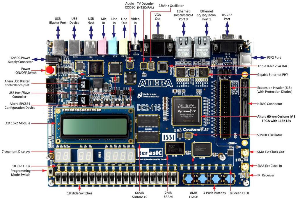
12 DE2_115_User_manual\DE2_115_User_manual.pd f 12
13 DE2_115_User_manual\DE2_115_User_manual.pd f Schematic Diagram 13
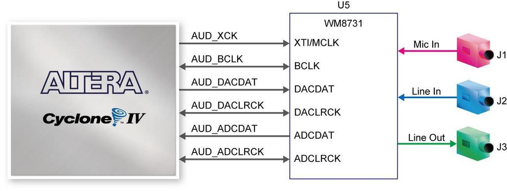
14 DE2_115_User_manual\DE2_115_User_manual.pd f Audio CODEC Pin Assignments Signal Name FPGA Pin No. Description I2C_SCLK PIN_B7 I2C Clock I2C_SDAT PIN_A8 I2C Data AUD_XCK PIN_E1 Audio CODEC Chip Clock AUD_BCLK PIN_F2 Audio CODEC Bit-Steam Clock AUD_ADCLRC K PIN_C2 Audio CODEC ADC LR Clock AUD_ADCDAT PIN_D2 Audio CODEC ADC Data AUD_DACLRC K PIN_E3 Audio CODEC DAC LR Clock AUD_DACDAT PIN_D1 Audio CODEC DAC Data Audio chip and TV decoder chip share one I2C bus 14

15 DE2_115_datasheets\Audio CODEC\WM8731.pdf WM8731 Block Diagram 15
16 DE2_115_datasheets\Audio CODEC\WM8731.pdf WM8731 Pin Configuration Top view of 28 pin QFN 16
17 DE2_115_schematic\DE2-115_MB.pdf 17
18 How to Use WM8731? 1. Initialize the device by setting the registers via I2C bus interface. 2. After correct initialization, we can receive or transmit audio data via digital audio interface. 18
19 Device Initialization 19
20 Software Control Interface (1/2) Different modes can be configured under software control. Input to ADC: Microphone Sampling rate: 32kHz Input audio data bit length: 16 bits etc. 20
21 Software Control Interface (2/2) Selection of serial control mode The serial control interface may be selected to operate in either 2 or 3-wire modes. This is achieved by setting the state of the MODE pin. MODE INTERFACE FORMAT 0 2 wire 1 3 wire 21
22 2-Wire Serial Control Mode The WM8731/L supports a 2-wire MPU (Microprocessor unit) interface, which is compatible with I²C protocol. I²C (Inter-Integrated Circuit, referred to as I- squared-c) uses only two bidirectional open-drain lines, Serial Data Line (SDA) and Serial Clock (SCL). 22
23 I²C protocol (1/4) Data transfer in initiated with the START bit (S) when SDA is pulled low while SCL stays high. SDA=1'b0 Then, SDA sets the transferred bit while SCL is low (blue) and the data is sampled (received) when SCL rises (green). 23
24 I²C protocol (2/4) When the transfer is complete, a STOP bit (P) is sent by releasing the data line to allow it to be pulled up while SCL is constantly high. In order to avoid false marker detection, the level on SDA is changed on the falling edge and is captured on the rising edge of SCL. SDA=1'b1 or SDA=1'bz 24
25 I²C protocol (3/4) After every 8 data bits in one direction, an "acknowledge" bit (0) is transmitted in the other direction. 25
26 I²C protocol (4/4) About inout port: module inout_port(oe, clk, SDA) input oe; // output enable input clk; inout SDA; wire a; // output data reg b; // input data assign SDA = oe? a: 1'bz; clk) begin b <= SDA; end 26
27 2-Wire Interface (1/2) The device operates as a slave device only. The WM8731/L has one of two slave address that are selected by setting the state of the CSB pin. CSB STATE ADDRESS
28 2-Wire Interface (2/2) 2-wire serial interface ADDR[6:0] (7 bits) are Slave Address Bits R/W is '0', indicating a write B[15:9] (7 bits) are Register Address Bits B[8:0] (9 bits) are Register Data Bits Max freq. = 526 khz 28
29 Register Map Check the WM8731/L document to see the details. 29
30 Left Line In REGISTER BIT[8] BIT[7] BIT[6] BIT[5] BIT[4] BIT[3] BIT[2] BIT[1] BIT[0] DEFAULT R0 (00h) Left Line In LRINBOTH LINMUTE 0 0 LINVOL[4:0] 0_1001_011 1 Just use the default setting if we do not use the line input. 000_0000_0_1001_
31 Right Line In REGISTER BIT[8] BIT[7] BIT[6] BIT[5] BIT[4] BIT[3] BIT[2] BIT[1] BIT[0] DEFAULT R1 (01h) Right Line In RLINBOTH RINMUTE 0 0 RINVOL[4:0] 0_1001_011 1 Just use the default setting if we do not use the line input. 000_0001_0_1001_
32 Left Headphone Out REGISTER BIT[8] BIT[7] BIT[6] BIT[5] BIT[4] BIT[3] BIT[2] BIT[1] BIT[0] DEFAULT R2 (02h) Left Headphone Out LRHPBOTH LZCEN LHPVOL[6:0] 0_0111_100 1 Here we can just use the default setting. 000_0010_0_0111_
33 Right Headphone Out REGISTER BIT[8] BIT[7] BIT[6] BIT[5] BIT[4] BIT[3] BIT[2] BIT[1] BIT[0] DEFAULT R3 (03h) Right Headphone Out RLHPBOTH RZCEN RHPVOL[6:0] 0_0111_100 1 Here we can just use the default setting. 000_0011_0_0111_
34 Analogue Audio Path Control REGISTER BIT[8] BIT[7] BIT[6] BIT[5] BIT[4] BIT[3] BIT[2] BIT[1] BIT[0] DEFAULT R4 (04h) Analogue Audio Path Control 0 SIDEATT[1:0] SIDETONE DACSEL BYPASS INSEL MUTEMIC MICBOOST 0_0000_101 0 Enable boost, disable mute, choose microphone input, disable bypass, and select DAC. 000_0100_0_0001_
35 Digital Audio Path Control REGISTER BIT[8] BIT[7] BIT[6] BIT[5] BIT[4] BIT[3] BIT[2] BIT[1] BIT[0] DEFAULT R5 (05h) Digital Audio Path Control HPOR DACMU DEEMPH[1:0] ADCHPD 0_0000_100 0 Disable soft mute 000_0101_0_0000_
36 Power Down Control REGISTER BIT[8] BIT[7] BIT[6] BIT[5] BIT[4] BIT[3] BIT[2] BIT[1] BIT[0] DEFAULT R6 (06h) Power Down Control 0 POWER OFF CLKOUTPD OSCPD OUTPD DACPD ADCPD MICPD LINEINPD 0_1001_111 1 Choose power on and disable all the power down options. 000_0110_0_0000_
37 Digital Audio Interface Format (1/2) REGISTER BIT[8] BIT[7] BIT[6] BIT[5] BIT[4] BIT[3] BIT[2] BIT[1] BIT[0] DEFAULT R7 (07h) Digital Audio Interface Format 0 BCLKIVE MS LRSWAP LRP IWL[[1:0] FORMAT[1:0] 0_0000_101 0 Choose I 2 S format, 16-bit length, and master mode. 000_0111_0_0100_
38 Digital Audio Interface Format (2/2) I 2 S format 16-bit length Master mode v.s. Slave mode 38
![Sampling Control (1/2) REGISTER BIT[8] BIT[7] BIT[6] BIT[5] BIT[4] BIT[3] BIT[2] BIT[1] BIT[0] DEFAULT R8 (08h) Sampling Control 0](/docs-images/83/88568744/images/39-3.jpg "CLKODIV2 CLKIDIV2 SR[3:0] BOSR USB/ Normal 0_0000_000 0 Choose USB mode (fixed MCLK 12MHz) and sampling rate = 32 khz.")
39 Sampling Control (1/2) REGISTER BIT[8] BIT[7] BIT[6] BIT[5] BIT[4] BIT[3] BIT[2] BIT[1] BIT[0] DEFAULT R8 (08h) Sampling Control 0 CLKODIV2 CLKIDIV2 SR[3:0] BOSR USB/ Normal 0_0000_000 0 Choose USB mode (fixed MCLK 12MHz) and sampling rate = 32 khz. 000_1000_0_0001_
40 Sampling Control (2/2) 40
41 Active Control REGISTER BIT[8] BIT[7] BIT[6] BIT[5] BIT[4] BIT[3] BIT[2] BIT[1] BIT[0] DEFAULT R9 (09h) Active Control Active 0_0000_000 0 Activate interface 000_1001_0_0000_
42 Reset Register REGISTER BIT[8] BIT[7] BIT[6] BIT[5] BIT[4] BIT[3] BIT[2] BIT[1] BIT[0] DEFAULT R15 (15h) Active Control RESET[8:0] not reset You can try to reset the device to a known (?) state. 000_1111_0_0000_0000 (?) 42
43 Recommended settings Left Line In Right Line In Left Headphone Out Right Headphone Out Analogue Audio Path Control Digital Audio Path Control Power Down Control Digital Audio Interface Format Sampling Control Active Control 000_0000_0_1001_ _0001_0_1001_ _0010_0_0111_ _0011_0_0111_ _0100_0_0001_ _0101_0_0000_ _0110_0_0000_ _0111_0_0100_ _1000_0_0001_ _1001_0_0000_
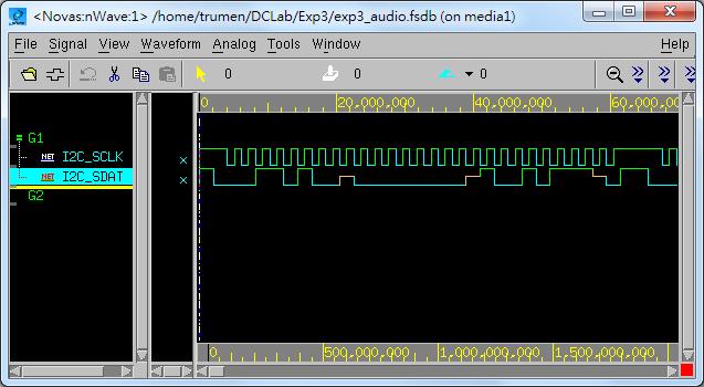
44 Check the Waveform _ _
45 _ _ Debug with LA 45
46 Device Operation 46
47 ADC The WM8731/L uses a multi-bit oversampled sigma-delta ADC. A single channel of the ADC is illustrated below. 47
48 ADC Filters The ADC filters perform true 24 bit signal processing to convert the raw multi-bit oversampled data from the ADC to the correct sampling frequency to be output on the digital audio interface. 48
49 Digital Audio Interfaces (1/5) WM8731/L may be operated in either one of the 4 offered audio interface modes. These are: Right justified Left justified I 2 S DSP mode All four of these modes are MSB first and operate with data 16 to 32 bits. 49
50 Digital Audio Interfaces (2/5) I 2 S mode Master mode n = 16, 20, 24, or 32 50
")
51 Digital Audio Interfaces (3/5) Record 51
52 Digital Audio Interfaces (4/5) Play 52
53 Digital Audio Interfaces (5/5) The length of the digital audio data is programmable at 16/20/24 or 32 bits. The data is signed 2's complement. If the ADC is programmed to output 16 or 20 bit data then it strips the LSBs from the 24 bit data. If the ADC is programmed to output 32 bits then it packs the LSBs with zeros. Similar adjustments in DAC. 53
54 DAC Filters The DAC filters perform true 24 bit signal processing to convert the incoming digital audio data from the digital audio interface at the specified sample rate to multi-bit oversampled data for processing by the analogue DAC. 54
55 DAC The WM8731/L employs a multi-bit sigma delta oversampling digital to analogue converter. 55
56 The End. Any question?
57 Reference "THE I 2C-BUS SPECIFICATION VERSION 2.1" by Philips. 4. "DE2-115 User Manual" by Terasic. 5. "DE2-115_MB.pdf" by Terasic. 6. "WM8731.pdf" by Wolfson Microelectronics. 57
Audio Controller i. Audio Controller
 i Audio Controller ii Contents 1 Introduction 1 2 Controller interface 1 2.1 Port Descriptions................................................... 1 2.2 Interface description.................................................
WM8721 Internet Audio DAC with Integrated Headphone Driver
 Internet Audio DAC with Integrated Headphone Driver, November 2000, Rev 1.3 DESCRIPTION The WM8721 is a low power stereo DAC with an integrated headphone driver. The WM8721 is designed specifically for
Low Power Audio Codec SSM2602
 Low Power Audio Codec FEATURES Stereo, 24-bit analog-to-digital and digital-to-analog converters DAC SNR: 100 db (A-weighted), THD: 80 db at 48 khz, 3.3 V ADC SNR: 90 db (A-weighted), THD: 80 db at 48
Low Power Audio Codec SSM2603
 Low Power Audio Codec FEATURES Stereo, 24-bit analog-to-digital and digital-to-analog converters DAC SNR: 100 db (A-weighted), THD: 80 db at 48 khz, 3.3 V ADC SNR: 90 db (A-weighted), THD: 80 db at 48
WM8711BL. Ultra-Small Audio DAC with Headphone Amplifier DESCRIPTION FEATURES APPLICATIONS BLOCK DIAGRAM WM8711B
 Ultra-Small Audio DAC ith Headphone Amplifier DESCRIPTION The is an ultra-small, lo poer stereo DAC ith an integrated headphone driver. It is designed specifically for portable audio systems requiring
WM8731L-6061-FL28-M-Rev1
 WM8731L-6061-FL28-M Example Configurations DOC TYPE: EXAMPLE CONFIGURATIONS BOARD REFERENCE: WM8731L-6061-FL28-M-Rev1 BOARD TYPE: Customer Mini Board WOLFSON DEVICE(S): WM8731L DATE: November 2007 DOC
Ah- Ah- Piu Final Project Presentation
 Ah- Ah- Piu Final Project Presentation Spring 2013 CSEE4840 Embedded System Design Final Project Hongsen Yu (hy2340) Xiaolong Jiang (xj2137) Junlin Lu (jl3925) Ji Pei (jp3242) Nan Li (nl2411) Overview
Altera DE1 Board DE1. Development and Education Board. User Manual. Copyright 2006 Altera Corporation
 Altera DE1 Board DE1 Development and Education Board User Manual Version 1.1 Copyright 2006 Altera Corporation Chapter 2 Altera DE1 Board This chapter presents the features and design characteristics of
February 2004 Digital Audio Products SLWS106H
 Data Manual February 2004 Digital Audio Products SLWS106H Contents Section Title Page 1 Introduction...................................................... 1 1 1.1 Features...................................................
iphone Noise Filtration Hardware
 Iowa State University ECPE Senior Design iphone Noise Filtration Hardware Design Plan Michael Bullis Andrew Mungons Yang Yang 2011 Client Rockwell Collins Faculty Advisor Dr. Zhengdao Wang G r o u p M
Pmod I2S2 Reference Manual
 Pmod I2S2 Reference Manual The Digilent Pmod I2S2 (Revision A) features a Cirrus CS5343 Multi Bit Audio A/D Converter and a Cirrus CS4344 Stereo D/A Converter, each connected to one of two audio jacks.
ALLO AUDIO CARDS TECHNICAL DETAILS
 ALLO AUDIO CARDS TECHNICAL DETAILS Revision: 1.1 Release Date: 09 Aug 2017 Contents Allo Piano DAC... 3 Allo Piano 2.1 DAC... 4 Allo Boss DAC & Allo Mini Boss DAC... 7 Allo Digione... 9 Allo Cheapo...
MARCH 2003 Digital Audio Products SLWS106G
 Data Manual MARCH 2003 Digital Audio Products SLWS106G IMPORTANT NOTICE Texas Instruments Incorporated and its subsidiaries (TI) reserve the right to make corrections, modifications, enhancements, improvements,
SRS WOW HD Processor. : I 2 C bus (standard-mode/100kbps, fast-mode/400kbps), 4-Wire Serial Bus (4-Wire: clock, enable, input data, output data)
, 4-Wire Serial Bus (4-Wire: clock, enable, input data, output data)") SRS WOW HD Processor General Description The NJU26040-09B is a digital audio signal processor that provides the function WOW HD (function limited edition of NJU29040-09A). The NJU26040-09B processes a
SRS WOW HD Processor General Description The NJU26040-09B is a digital audio signal processor that provides the function WOW HD (function limited edition of NJU29040-09A). The NJU26040-09B processes a
Introduction to I2C & SPI. Chapter 22
 Introduction to I2C & SPI Chapter 22 Issues with Asynch. Communication Protocols Asynchronous Communications Devices must agree ahead of time on a data rate The two devices must also have clocks that are
SRS TruSurround HD/HD4 Decoder
 SRS TruSurround HD/HD4 Decoder General Description The NJU26040-09D is a digital audio signal processor that provides the function of TruSurround HD/HD4 FOCUS and WOW HD. The NJU26040-09D processes all
Design and development of embedded systems for the Internet of Things (IoT) Fabio Angeletti Fabrizio Gattuso
 Fabio Angeletti Fabrizio Gattuso") Design and development of embedded systems for the Internet of Things (IoT) Fabio Angeletti Fabrizio Gattuso Microcontroller It is essentially a small computer on a chip Like any computer, it has memory,
Design and development of embedded systems for the Internet of Things (IoT) Fabio Angeletti Fabrizio Gattuso Microcontroller It is essentially a small computer on a chip Like any computer, it has memory,
Inter-Integrated Circuit Bus IIC I2C TWI
 Inter-Integrated Circuit Bus IIC TWI Bus Synchronous, multi-master, multi-slave, packet switched, single ended serial bus Developed by Philips in the early 1980 s (prior to SPI) Intended for on-board communications
Brick Breaker Game. Spring Team Members: Fengyi Song(fs2523), Junchao Zhang(jz2606), Mingrui Liu (ml3663), Wanding Li(wl2501)
, Junchao Zhang(jz2606), Mingrui Liu (ml3663), Wanding Li(wl2501)") Brick Breaker Game Team Members: Fengyi Song(fs2523), Junchao Zhang(jz2606), Mingrui Liu (ml3663), Wanding Li(wl2501) I. Introduction and Overview We will implement a simple brick game. Here is how simple
Brick Breaker Game Team Members: Fengyi Song(fs2523), Junchao Zhang(jz2606), Mingrui Liu (ml3663), Wanding Li(wl2501) I. Introduction and Overview We will implement a simple brick game. Here is how simple
Web Site: Forums: forums.parallax.com Sales: Technical:
 Web Site: www.parallax.com Forums: forums.parallax.com Sales: sales@parallax.com Technical: support@parallax.com Office: (916) 624-8333 Fax: (916) 624-8003 Sales: (888) 512-1024 Tech Support: (888) 997-8267
Using an Analog Devices AD774X Capacitance-to-Digital Converter for Differential Button Sensor Operation
 Using an Analog Devices AD774X Capacitance-to-Digital Converter for Differential Button Sensor Operation Eric Otte April 3 rd, 2010 ECE 480 Executive Summary: Capacitive sensors are increasingly being
Codec. WM8731 Audio Codec
 Codec WM8731 Audio Codec Codec Coder / Decoder Audio, Video Compression/decompression signal coding 2 tj WM8731 3 tj WM8731 Data Path Basic Connection 4 tj WM8731 Data Path Basic Timing 5 tj WM8731 Data
Overview. Features. Technical Data Sheet 1 / 6. Mixing Console MG10. MG10 is a versatile mixer suitable for a wide range of users and applications.
 Overview MG10 is a versatile mixer suitable for a wide range of users and applications. Rear Panel Features Input channels: 10 Line Inputs (4 mono, 3 stereo), 4 Mic Inputs with 48V phantom power and HPH
User Guide for MA Evaluation Boards MA12040/MA12040P/MA12070/MA12070P
 User Guide for MA Evaluation Boards MA12040/MA12040P/MA12070/MA12070P About this document Scope and purpose The Evaluation Board is an evaluation and demonstration board for MA12040, MA12040P, MA12070,
Microcontrollers and Interfacing
 Microcontrollers and Interfacing Week 10 Serial communication with devices: Serial Peripheral Interconnect (SPI) and Inter-Integrated Circuit (I 2 C) protocols College of Information Science and Engineering
16-Bit Stereo Audio DAC & Headphone Driver Single Supply Voltage and Low Voltage Low Power Consumption 8.9mW Mute And Power Down Function VOL-IN
 Single Supply Voltage and Low Voltage Low Power Consumption 8.9mW Mute And Power Down Function FEATURES Operation range: 2.5V~6.5V Excellent Power Supply Rejection Ratio(PSRR) Reduced pop-noise circuit
Tutorial for I 2 C Serial Protocol
 Tutorial for I 2 C Serial Protocol (original document written by Jon Valdez, Jared Becker at Texas Instruments) The I 2 C bus is a very popular and powerful bus used for communication between a master
: In Master mode, MCK = 256fs, MCK2 = 512fs
 SRS CS Auto & CSII 5.1 & TruSurround XT Decoder General Description The NJU26208 is a digital signal processor that provides the function of Circle Surround Automotive / Circle SurroundII5.1 / TruSurroundXT
Altimeter / Barometer Module SMD500 ultra low power, low voltage
 Altimeter / Barometer Module SMD500 ultra low power, low voltage 1. General Description The SMD500 marks a new generation of high precision digital pressure sensors for consumer applications. Its ultra
CW2013. Low-Cost 1s Fuel Gauge IC with Low-SOC Alert. General Description. Features. Applications. Order Information
 CW2013 Low-Cost 1s Fuel Gauge IC with Low-SOC Alert Features System Side used Fuel Gauging 3% Maximum Total SOC Measurement Error 14 bit Delta Sigma ADC for Temperature and Cell Voltage Measurement Precision
Basic Concepts. Task One: The Basic Latch. Laboratory Nine Latches, RAM & Android Architecture
 Laboratory Nine Latches, RAM & Android Architecture Basic Concepts 1. The most basic element of binary storage is the latch, consisting of 2 cross-coupled NAND (or NOR) gates. 2. The D-latch with Enable
How to Implement I 2 C Serial Communication Using Intel MCS-51 Microcontrollers
 APPLICATION NOTE How to Implement I 2 C Serial Communication Using Intel MCS-51 Microcontrollers SABRINA D QUARLES APPLICATIONS ENGINEER April 1993 Order Number 272319-001 Information in this document
Level Shifter. for. Hardware User s Manual.
 Level Shifter for USB-to to-i2c Hardware User s Manual https://www.i2ctools.com/ Information provided in this document is solely for use with the I2C and SPI Level Shifter from SB Solutions, Inc. SB Solutions,
ES8374. Low Power Mono Audio CODEC FEATURES APPLICATIONS ORDERING INFORMATION DAC. System
 Low Power Mono Audio CODEC ES874 FEATURES System High performance and low power multibit delta-sigma audio ADC and DAC I S/PCM master or slave serial data port Two pairs of analog input with differential
Evaluation Board for CS4245
 Features Single-ended Analog Inputs Single-ended Analog Outputs Evaluation Board for CS4245 CS8406 S/PDIF Digital Audio Transmitter CS8416 S/PDIF Digital Audio Receiver Independent ADC and DAC Clock Domains
Streamer Max MKII. Bidirectional Encoder/Decoder for streaming audio over IP MAIN FEATURES
 Bidirectional Encoder/Decoder for streaming audio over IP BUY MAIN FEATURES Bidirectional Encoder/Decoder for streaming audio over IP. Analog and AES/EBU I/O. Formats: PCM, MP3, AAC (separated license
Pmod modules are powered by the host via the interface s power and ground pins.
 1300 Henley Court Pullman, WA 99163 509.334.6306 www.store. digilent.com Digilent Pmod Interface Specification 1.2.0 Revised October 5, 2017 1 Introduction The Digilent Pmod interface is used to connect
Lecture 25 March 23, 2012 Introduction to Serial Communications
 Lecture 25 March 23, 2012 Introduction to Serial Communications Parallel Communications Parallel Communications with Handshaking Serial Communications Asynchronous Serial (e.g., SCI, RS-232) Synchronous
Fully Integrated Thermal Accelerometer MXC6225XU
 Powerful Sensing Solutions for a Better Life Fully Integrated Thermal Accelerometer MXC6225XU Document Version 1.0 page 1 Features General Description Fully Integrated Thermal Accelerometer X/Y Axis, 8
Not Recommended for New Designs TAS3108, TAS3108IA AUDIO DIGITAL SIGNAL PROCESSORS SLES152B OCTOBER 2005 REVISED NOVEMBER 2007
 TAS318, TAS318IA 1 Introduction 1.1 Features 8 channel Programmable Audio Digital Signal 16-, 2-, 24-, and 32-Bit Word Sizes Processor (DSP) 64-f S, 128-f S, 192-f S, and 256-f S SCLK to 135-MHz Maximum
MSI-P400 PC/104 QUADRATURE DECODER/COUNTER CARD. PC/104 Embedded Industrial Analog I/O Series. Microcomputer Systems, Inc.
 MSI-P400 PC/104 QUADRATURE DECODER/COUNTER CARD PC/104 Embedded Industrial Analog I/O Series Microcomputer Systems, Inc. 1814 Ryder Drive Baton Rouge, LA 70808 Ph (225)769-2154 Fax (225) 769-2155 http://www.microcpmputersystems.com
SILICON MICROSTRUCTURES
 Digital Communication with SM5800 Series Parts OVERVIEW The SM5800 series pressure product offers the corrected pressure output in both analog and digital formats. Accessing the analog output is an easy
Digital Signal Processor for TV
 Digital Signal Processor for TV General Description The NJU26041-01A is a high performance 24-bit digital signal processor. The NJU26041-01A provides eala 3D Surround function, ealabass Dynamic Bass Boost
GWK5Mx 2.4GHz Wireless Audio Module
 GWK5Mx 2.4GHz Wireless Audio Module 1. General Description GWK5Mx is the module version of Gigawit GWK5 family wireless digital audio products. GWK5MO is 0dBm and GWK5MP is 18dBm, it can be easily integrate
University Program Advance Material
 University Program Advance Material Advance Material Modules Introduction ti to C8051F360 Analog Performance Measurement (ADC and DAC) Detailed overview of system variances, parameters (offset, gain, linearity)
LM4934 I2C/SPI Interface Software Manual v1.0
 LM4934 I2C/SPI Interface Software Manual v1.0 National Semiconductor Application Note 1492 Daniel Andersen May 2006 Table of Contents Introduction... 2 Installation... 2 Overview... 2 Default All Button...
Development and research of different architectures of I 2 C bus controller. E. Vasiliev, MIET
 Development and research of different architectures of I 2 C bus controller E. Vasiliev, MIET I2C and its alternatives I²C (Inter-Integrated Circuit) is a multi-master serial computer bus invented by Philips
TAS3108/TAS3108IA AUDIO DSP
 www.ti.com TAS3108/TAS3108IA AUDIO DSP 1 Introduction 1.1 Features 8-Channel Programmable Audio Digital Signal 16-, 20-, 24-, and 32-Bit Word Sizes Processor (DSP) 64-f S, 128-f S, 192-f S, and 256-f S
CalArts Film/Video Sound Quick Start for Sound Devices 744T Time Code Hard Drive Field Recorder:
 CalArts Film/Video Sound Quick Start for Sound Devices 744T Time Code Hard Drive Field Recorder: Front Panel Descriptions 1) Digital Input LEDs! Indicates the presence of digital signal on the respective
Lecture 5: Computing Platforms. Asbjørn Djupdal ARM Norway, IDI NTNU 2013 TDT
 1 Lecture 5: Computing Platforms Asbjørn Djupdal ARM Norway, IDI NTNU 2013 2 Lecture overview Bus based systems Timing diagrams Bus protocols Various busses Basic I/O devices RAM Custom logic FPGA Debug
DEV-1 HamStack Development Board
 Sierra Radio Systems DEV-1 HamStack Development Board Reference Manual Version 1.0 Contents Introduction Hardware Compiler overview Program structure Code examples Sample projects For more information,
Digital Signal Processor for Car Audio
 Digital Signal Processor for Car Audio General Description The NJU26202 is a digital signal processor that provides the function of Circle Surround Automotive, Hall Simulator, 7Band PEQ / GEQ, and Time
SL Interpreter Compact
 SL Interpreter Compact Interpreter Console FEATURES stand-alone console, no need for external equipment individual volume and tone controls for 2 interpreters built-in distribution amplifier allows easy
Comtrue Inc. CT7302 EVM D C LQFP 48 Evaluation board Application Note
 Overview Comtrue Inc. CT7302 EVM D C LQFP 48 The CT7302 serial chip is a high performance single chip digital audio bridge with sample rate converter. It supports the DSD I/F and DoP on S/PDIF input/output
Overview. Features. Technical Data Sheet 1 / 6. Mixing Console AG03
 Overview AG03 is a multi-purpose mixer with USB audio interface, especially optimized for webcasting. Rear Panel Features Input channels: 3 Line Inputs (1 mono, 1 stereo), 1 Mic Inputs with 48V phantom
2-Wire, 5-Bit DAC with Three Digital Outputs
 Rev 1; 6/4 2-Wire, 5-Bit DAC with Three Digital Outputs General Description The is a 5-bit digital-to-analog converter (DAC) with three programmable digital outputs. The communicates through a 2-wire,
PLATINUM BY MSB TECHNOLOGY
 Features Designed specifically for high resolution digital audio True voltage output, no I/V converter required Low unbuffered output impedance 500 Ohms Built in high speed buffer (B only) Ultra high dynamic
User-configurable Resolution. 9 to 12 bits (0.5 C to C)
") AT30TS74 9- to 12-bit Selectable, ±1.0 C Accurate Digital Temperature Sensor DATASHEET Features Single 1.7V to 5.5V Supply Measures Temperature From -55 C to +125 C Highly Accurate Temperature Measurements
AT30TS74 9- to 12-bit Selectable, ±1.0 C Accurate Digital Temperature Sensor DATASHEET Features Single 1.7V to 5.5V Supply Measures Temperature From -55 C to +125 C Highly Accurate Temperature Measurements
GWBMA0x Bluetooth Audio module
 GWBMA0x Bluetooth Audio module Data sheet version 0.9 draft GWBMA0X DATASHEET 0.9 GIGAWIT 1 Introduction GWBMA1X is a high performance Bluetooth audio module, It provides various type of wireless audio
Overview. Features. Technical Data Sheet 1 / 6. Mixing Console AG06
 Overview AG6 is a multi-purpose mixer with USB audio interface, especially optimized for webcasting. Rear Panel Features Input channels: 6 Line Inputs (2 mono, 2 stereo), 2 Mic Inputs with 48V phantom
Arduino Uno R3 INTRODUCTION
 Arduino Uno R3 INTRODUCTION Arduino is used for building different types of electronic circuits easily using of both a physical programmable circuit board usually microcontroller and piece of code running
UAC 3576B USB Audio Codec
 APPLICATION NOTE KITS/BOARDS MICRONAS UAC 76B USB Audio Codec Edition Dec., 00 6-68--AK MICRONAS UAC 76B APPLICATION NOTE KITS/BOARDS Contents Page Section Title. Introduction.. Quick Start.. LED. Connectivity..
Interfacing I2S DAC. Public Document. VS10XX AppNote: I2S DAC
 : I2S DAC Description This document describes how to interface VS10XX to an I2S DAC. It shows an example schematic and shows the required register settings. This document applies to VS1033. For detailed
Audio Codec Snap On Board
 Audio Codec Snap On Board Reference Manual, Inc. (USA) 14100 Murphy Avenue San Martin, CA 95046 (408) 852-0067 http://www.slscorp.com Board Version: 1.0 Document Version: 1.2 Document Date: Copyright 2005-2009,,
Symphony SoundBite Reference Manual
 Symphony SoundBite Reference Manual Document Number: SNDBITERM Rev. 2.0 09/2008 Contents Section 1, Introduction page 2 Section 2, Functional Blocks page 3 Section 3, Configuration and Connections page
DS1845 Dual NV Potentiometer and Memory
 www.maxim-ic.com FEATURES Two linear taper potentiometers -010 one 10k, 100 position & one 10k, 256 position -050 one 10k, 100 position & one 50k, 256 postition -100 one 10k, 100 position & one 100k, 256
DHANALAKSHMI COLLEGE OF ENGINEERING, CHENNAI DEPARTMENT OF ELECTRICAL AND ELECTRONICS ENGINEERING. EE Microcontroller Based System Design
 DHANALAKSHMI COLLEGE OF ENGINEERING, CHENNAI DEPARTMENT OF ELECTRICAL AND ELECTRONICS ENGINEERING EE6008 - Microcontroller Based System Design UNIT III PERIPHERALS AND INTERFACING PART A 1. What is an
Enhanced Closed-loop Trim with I 2 C Control for Platform Manager Devices
 Enhanced Closed-loop Trim with I 2 C Control for Platform Manager Devices December 2010 Introduction Reference Design RD1078 Modern microprocessors and FPGAs require accurate power supply voltages, often
Manual iaq-engine Indoor Air Quality sensor
 Manual iaq-engine, Version 2.0 May 2011 (all data subject to change without notice) Manual iaq-engine Indoor Air Quality sensor Digital and analog I/O SMD type package Product summary iaq-engine is used
Digital Thermometer and Thermostat
 General Description The DS75LV low-voltage (1.7V to 3.7V) digital thermometer and thermostat provides 9, 10, 11, or 12-bit digital temperature readings over a -55 C to +125 C range with ±2 C accuracy over
Shanghai Belling Corp., Ltd BL55028 zip: Tel: Fax:
 LCD Driver for 76 Display Units BL55028 1 General Description The BL55028 is a general LCD driver IC for 76 units LCD panel. It features a wide operating supply voltage range, incorporates simple communication
HD/SD H.264 Capture Device (H.264 Video Encoder + Decoder) User s Manual Model 2226 Rev.A March 2010
 User s Manual Model 2226 Rev.A March 2010") HD/SD H.264 Capture Device (H.264 Video Encoder + Decoder) User s Manual Model 2226 Rev.A March 2010 Table of Contents TABLE OF CONTENTS...2 LIMITED WARRANTY...4 SPECIAL HANDLING INSTRUCTIONS...5 INTRODUCTION...6
HD/SD H.264 Capture Device (H.264 Video Encoder + Decoder) User s Manual Model 2226 Rev.A March 2010 Table of Contents TABLE OF CONTENTS...2 LIMITED WARRANTY...4 SPECIAL HANDLING INSTRUCTIONS...5 INTRODUCTION...6
OVERVIEW SYSTEM REQUIREMENTS
 USER GUIDE OVERVIEW The AI-1 USB Audio Interface adds studio-quality Input and Output capabilities to your PC or Mac, turning your recording software into a full recording setup. With its high quality
Solid State System Co., Ltd.
 Solid State System Co., Ltd. Declaration The information contained herein is for evaluation and reference purpose only. The incorporation of such products and information in the design of customers products
User-configurable Resolution. 9 to 12 bits (0.5 C to C)
") AT30TS75A 9- to 12-bit Selectable, ±0.5 C Accurate Digital Temperature Sensor DATASHEET See Errata in Section 12. Features Single 1.7V to 5.5V Supply Measures Temperature -55 C to +125 C Highly Accurate
AT30TS75A 9- to 12-bit Selectable, ±0.5 C Accurate Digital Temperature Sensor DATASHEET See Errata in Section 12. Features Single 1.7V to 5.5V Supply Measures Temperature -55 C to +125 C Highly Accurate
App Note Application Note: Addressing Multiple FPAAs Using a SPI Interface
 Rev: 1.0.0 Date: 23 rd Jan 2015 App Note - 310 Application Note: Addressing Multiple FPAAs Using a SPI Interface TABLE OF CONTENTS 1 PURPOSE... 2 2 THE SPI INTERFACE... 3 2.1 OVERVIEW... 3 2.2 DETAILED
Network Upgrade for the LINK DAC III
 Network Upgrade for the LINK DAC III Rev #3 (6/2001) Users Manual Thank you for purchasing the Network Upgrade for your LINK DAC. I am sure you will be very pleased with it. It adds the following new features
THANG LUONG CAO. Serial bus adapter design for FPGA. Master of Science Thesis
 THANG LUONG CAO Serial bus adapter design for FPGA Master of Science Thesis Examiner: Prof. Timo D. Hämäläinen Examiner and topic approved by the Faculty Council of the Faculty of Computing and Electrical
Users Manual. KAS Walleye Microphone Evaluation Kit
 Users Manual KAS-33100-00 Walleye Microphone Evaluation Kit KAS-33100-00 Kit Description The KAS-33100-00 Walleye microphone evaluation kit allows for simple and easy evaluation of SiSonic MEMS microphones.
MG12XU Overview Features Technical Data Sheet
 Overview MG12XU is a versatile mixer suitable for a wide range of users and applications. Rear Panel Features Input channels: 12 Line Inputs (4 mono, 4 stereo), 6 Mic Inputs with 48V phantom power and
1 The Attractions of Soft Modems
 Application Note AN2451/D Rev. 0, 1/2003 Interfacing a Low Data Rate Soft Modem to the MCF5407 Microprocessor The traditional modem has been a box or an add-on card with a phone connection on one end and
DigiAudio. User Manual. Digital Audio Development and I/O Board. coreworks, lda. CWdab01 - DigiAudio DIGITAL AUDIO DEVELOPMENT I/O BOARD
 DigiAudio Digital Audio Development and I/O Board User Manual 1 TABLE OF CONTENTS FEATURES...3...4 POWER SUPPLY...5 JUMPER SETTINGS...5 MPEG AUDIO CLOCK SYNTHESIZER (CKS)...5 PLL CIRCUITS (PLL1 and PLL2)...6
Modern Robotics Inc. Sensor Documentation
 Sensor Documentation Version 1.0.1 September 9, 2016 Contents 1. Document Control... 3 2. Introduction... 4 3. Three-Wire Analog & Digital Sensors... 5 3.1. Program Control Button (45-2002)... 6 3.2. Optical
SiSonic FLEX Evaluation Kit KAS USER GUIDE.
 Contents 1. Digital to Analog Converter (DAC) PCB 2. Mic-On-Flex Assemblies (10 Total) 3. Adapter PCBs (Digital and Analog) 1 2 3 Description The evaluation kit allows for simple and easy evaluation of
Introduction Testing analog integrated circuits including A/D and D/A converters, requires a special digital interface to a main controller. The digit
 FPGA Interface for Signal Handling (FISH) Mohsen Moussavi Catena Networks April 2000 Introduction Testing analog integrated circuits including A/D and D/A converters, requires a special digital interface
Parallel Data Transfer. Suppose you need to transfer data from one HCS12 to another. How can you do this?
 Introduction the Serial Communications Huang Sections 9.2, 10.2, 11.2 SCI Block User Guide SPI Block User Guide IIC Block User Guide o Parallel vs Serial Communication o Synchronous and Asynchronous Serial
19.1. Unit 19. Serial Communications
 9. Unit 9 Serial Communications 9.2 Serial Interfaces Embedded systems often use a serial interface to communicate with other devices. Serial implies that it sends or receives one bit at a time. µc Device
TEXAS INSTRUMENTS ANALOG UNIVERSITY PROGRAM DESIGN CONTEST MIXED SIGNAL TEST INTERFACE CHRISTOPHER EDMONDS, DANIEL KEESE, RICHARD PRZYBYLA SCHOOL OF
 TEXASINSTRUMENTSANALOGUNIVERSITYPROGRAMDESIGNCONTEST MIXED SIGNALTESTINTERFACE CHRISTOPHEREDMONDS,DANIELKEESE,RICHARDPRZYBYLA SCHOOLOFELECTRICALENGINEERINGANDCOMPUTERSCIENCE OREGONSTATEUNIVERSITY I. PROJECT
User s Guide. IP-201 I2C Bus Multiplexer Board Revision 1. Micro Computer Control Corporation
 User s Guide IP-201 I2C Bus Multiplexer Board Revision 1 Micro Computer Control Corporation www.mcc-us.com 4 Channel I 2 C Multiplexer Board Model IP-201 User, s Guide Overview I 2 C Bus is the Inter-Integrated
NAU85L40 Evaluation Board. User Manual. Nuvoton Technology Corporation America Tel: Fax: Rev. 0.
 NAU85L40 Evaluation Board User Manual 1 Version 2.0 User Manual Contents 1 INTRODUCTION... 4 2 SETUP... 6 2.1 Power Connectors... 6 2.2 Analog Input Connector... 7 2.3 I 2 S I/O Ports... 9 2.4 Jumper setting
UART TO SPI SPECIFICATION
 UART TO SPI SPECIFICATION Author: Dinesh Annayya dinesha@opencores.org Table of Contents Preface... 3 Scope... 3 Revision History... 3 Abbreviations... 3 Introduction... 3 Architecture... 4 Baud-rate generator
PAN502x Capacitive Touch Controller Datasheet
 PAN502x Capacitive Touch Controller sheet PAN502x-A-A, Rev 1.0 Panchip Microelectronics www.panchip.com Copyright@2014, Panchip Microelectronics, CO., LTD. All right reserved. 1 / 16 Table of Contents
User Operating Manual
 A T C C D A 2 User Operating Manual ACOUSTIC ENGINEERS CD Player CDA2 Description The CDA2 Stereo CD Pre-Amplifier has been designed to partner ATC active, and with an appropriate Power Amplifier, passive
White Paper Using the MAX II altufm Megafunction I 2 C Interface
 White Paper Using the MAX II altufm Megafunction I 2 C Interface Introduction Inter-Integrated Circuit (I 2 C) is a bidirectional two-wire interface protocol, requiring only two bus lines; a serial data/address
CDB4244. Evaluation Board. Description. Features CS4244. Multiple Analog Input Filter Options Active Single Ended to Differential Passive Differential
 CS4244 Evaluation Board Features Description Multiple Analog Input Filter Options Active Single Ended to Differential Passive Differential Multiple Analog Output Filter Options Passive Single Ended & Differential
OOB (1) Detection Module, With I 2 C Interface Accelerometer
 Detection Module, With I 2 C Interface Accelerometer") OOB (1) Detection Module, With I 2 C Interface Accelerometer MXC62020GMW FEATURES Small package: 28.6mm X 15mm X 9mm High resolution rated at 1 milli-g Fast I2C slave (400 KHz.) mode interface 1.8V compatible
OOB (1) Detection Module, With I 2 C Interface Accelerometer MXC62020GMW FEATURES Small package: 28.6mm X 15mm X 9mm High resolution rated at 1 milli-g Fast I2C slave (400 KHz.) mode interface 1.8V compatible
17. I 2 C communication channel
 17. I 2 C communication channel Sometimes sensors are distant to the microcontroller. In such case it might be impractical to send analog signal from the sensor to the ADC included in the microcontroller
McMaster University Embedded Systems. Computer Engineering 4DS4 Lecture 6 Serial Peripherals Amin Vali Feb. 2016
 McMaster University Embedded Systems Computer Engineering 4DS4 Lecture 6 Serial Peripherals Amin Vali Feb. 2016 Serial Peripherals I2C Inter-IC Bus X/Y Coord. RGB data LCD config controller LCD data controller
1.3inch OLED User Manual
 1.3inch OLED User Manual 1. Key Parameters Table 1: Key Parameters Driver Chip SH1106 Interface 3-wire SPI 4-wire SPI I2C Resolution 128*64 Display Size 1.3 inch Dimension 29mm*33mm Colors Yellow, Blue