CAN-GW100/RS232. RS232-CAN Converter HARDWARE MANUAL ENGLISH
|
|
|
- Clementine Warren
- 6 years ago
- Views:
Transcription

1 CAN-GW100/RS232 RS232-CAN Converter HARDWARE MANUAL ENGLISH
2 HMS Technology Center Ravensburg GmbH Helmut-Vetter-Straße Ravensburg Germany Tel.: Fax: Internet: info-ravensburg@hms-networks.de Support For problems or support with this product or other HMS products please request support at Further international support contacts can be found on our webpage Copyright Duplication (copying, printing, microfilm or other forms) and the electronic distribution of this document is only allowed with explicit permission of HMS Technology Center Ravensburg GmbH. HMS Technology Center Ravensburg GmbH reserves the right to change technical data without prior announcement. The general business conditions and the regulations of the license agreement do apply. All rights are reserved. Registered trademarks All trademarks mentioned in this document and where applicable third party registered are absolutely subject to the conditions of each valid label right and the rights of particular registered proprietor. The absence of identification of a trademark does not automatically mean that it is not protected by trademark law. Document number: Version: 1.6
3 Content 1 Lead-in Overview Connections Connector Allocation Power Supply (X1) Serial Interface RS232 (X2) CAN (X3) Ground Connections Description of Functions Introduction RS232-CAN Gateway RS232-CANopen Gateway Data Structure of the Configuration Files General Settings [General] Product Name (ProductName) Version Number (TemplateVersion) Operation Mode (OperationMode) Timeout User Settings [User] Configuration Name (ConfigAlias) RS232 Settings [RS232] Baudrate (RS232baudrate) Number of Databits (Databits) Parity (Parity) Flow Control (Handshake) CAN-GW100/RS232 Settings [CANmode] Baudrate (CANbaudrate) Frame Format (FrameFormat) Send Identifier (SendID) Receive Identifier (ReceiveID) CAN-GW100/RS232 Settings [COPmode] Baudrate (CANopenBaudrate) CANopen Node Number (CANopenNode) Heartbeat Time (HBTime) Receive PDO (RxPDO) Receive PDO Type (RxPDOtype) Transmit-PDO (TxPDO) Transmit-PDO Type (TxPDOtype) CAN-GW100/RS232 Manual, Version 1.6
4 Content Byte Stream Flow Control (ByteStreamExtension) Default Configuration Download Tool Configuration with Windows Console Program Creating a Configuration File Download of a Configuration Displaying the Current Configuration Saving the Current Configuration Configuration Tool Configuration with Windows Application Default Configuration Loading and Saving a Configuration Setting up a Connection Reading the Current Configuration Downloading a Configuration Disconnecting Configuration Cable Displays Normal Mode Power LED CAN LED Status LED RS232 LED Configuration Mode Error State Notes on EMC Shield Concept Appendix Support Returning Hardware Technical Specifications Sources of Data Sheets EC Conformity Declaration CAN-GW100/RS232 Manual, Version 1.6
5 Lead-in 1 Lead-in 1.1 Overview Congratulations on your purchase of the IXXAT CAN-GW100/RS232, a highquality electronic component developed and manufactured according to the latest technological standards. This manual is intended to familiarize you with your CAN-GW100/RS232. Please read this manual before initial startup. The CAN-GW100/RS232 enables devices with only one serial port a simple, configurable access to CAN and CANopen networks. CAN-GW100/RS232 provides two operation modes for this purpose. In the CAN operation mode (CANmode), received CAN data are transmitted transparently to the RS232 interface. Data received via RS232 are mapped into CAN telegrams and transmitted. One configurable identifier each is available for transmission and reception. In the CANopen operation mode (COPmode), the CAN-GW100/RS232 operates as a CANopen node, where the serial data are stored as a byte stream object in the manufacturer-specific object dictionary range. The supported CANopen features are: 1 server SDO expedited, non-expedited, no CRC check 1 TX PDO static mapping 1 RX PDO static mapping Emergency message Heartbeat producer NMT slave The communication interfaces and operation modes are configured by means of a configuration file, which is saved on the device via a loading program. 5 CAN-GW100/RS232 Manual, Version 1.6

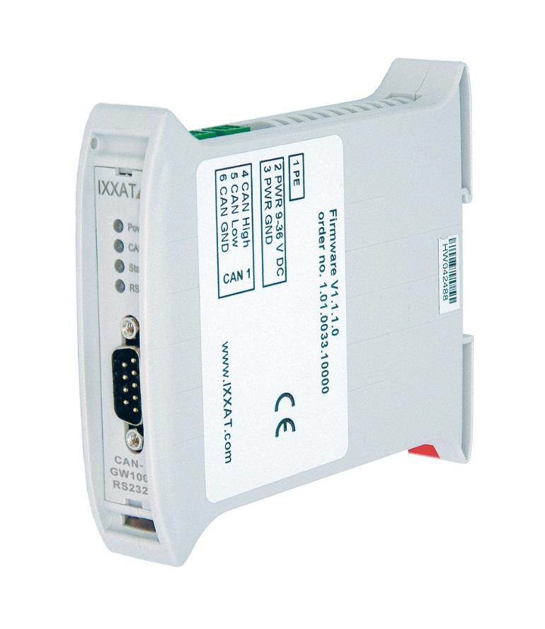
6 Connections 2 Connections 2.1 Connector Allocation The pin allocation for the Industrial DIN rail version is shown in Fig Fig. 2-1: Connector arrangement Power Supply (X1) The device is supplied with DC voltage of 9 V - 36 V. The pin allocation is shown in Table 2-1. The CAN-GW100/RS232 is protected against polarity reversal, under-voltage and over-voltage. In the event of polarity reversal or under-voltage, it is switched off, with overvoltage an internal fuse is triggered. Terminal Table 2-1: Terminal allocation Power Signal 1 PE 2 PWR (+) 3 GND (-) 6 CAN-GW100/RS232 Manual, Version 1.6
7 Connections Serial Interface RS232 (X2) The signals of the serial port are connected to the 9-pin Sub-D connector X2 (see Table 2-2). Pin no. X2 Signal 1 DCD 2 RX 3 TX 4 DTR 5 GND 6 DSR 7 RTS 8 CTS 9 RI Table 2-2: Pin allocation RS CAN (X3) CAN is available on X3 with a bus interface according to ISO (see Table 2-3). Terminal Table 2-3: Terminal allocation CAN1 Signal 4 CAN High 5 CAN Low 6 GND 2.2 Ground Connections In the galvanically isolated version, the GND of CAN (X3) is isolated from the rest of the circuit, the GND of the serial port (X2) is connected to the GND of the power supply (X1). In the version without galvanic isolation, all GND connections (X1, X2, X3) are connected with each other. The shield connection of the serial port (X2) and the PE connection (X1 terminal 1) are connected with each other both in the version with and in the version without galvanic isolation. 7 CAN-GW100/RS232 Manual, Version 1.6
8 Description of Functions 3 Description of Functions 3.1 Introduction The CAN-GW100/RS232 offers the two operation modes CANmode (RS232- CAN Gateway) and COPmode (RS232-CANopen Gateway). In CANmode, the device transmits the data that arrives on the serial port to the CAN bus under a configurable identifier. In the same way, data that are received via CAN by means of another configurable identifier are passed on to the serial port. The identifiers, CAN parameters and the parameters of the serial port used can be freely configured. In COPmode, the databytes that arrive on the serial port are transmitted on the CAN bus via TxPDO. Conversely, the data received via a certain RxPDO are passed on to the serial port. On the CANopen side, the Byte Stream Protocol is used as the communication protocol. The CAN-GW100/RS232 can be configured via the serial port with the aid of a download tool. 3.2 RS232-CAN Gateway Table 3-1 shows the functions and the associated key words, relevant for the CANmode. Function Possible settings Key words Operation mode CANmode OperationMode (under [General]) Timeout 0-6,5 s Timeout (under [General]) RS232 parameter Baudrate for CAN bus Frame Format for CAN bus 1. Baudrate 2. Number of databits 3. Parity 4. Flow control 1. Setting of a CiA baudrate 2. Setting the bus timing register BTR0 / BTR1 1. Standard Frame Format (11bit identifier) 2. Extended Frame Format (29 bit identifier) RS232baudrate Databits Parity Handshake (all under [RS232]) CANbaudrate (under [CANBus]) FrameFormat (under [CANBus]) 8 CAN-GW100/RS232 Manual, Version 1.6
9 Description of Functions CAN identifier for transmission of the data to the CAN bus CAN identifier for receiving data from CAN bus Table 3-1 All CAN identifiers are possible All CAN identifiers are possible SendID (under [CANmode]) ReceiveID (under [CANmode]) 3.3 RS232-CANopen Gateway Table 3-2 shows the functions and the associated key words, relevant for the COPmode. Function Possible settings Key words Operation mode COPmode OperationMode (under [General]) Timeout 0-6,5 s Timeout (under [General]) RS232 parameter 1. Baudrate 2. Number of databits 3. Parity 4. Flow control RS232baudrate Databits Parity Handshake (all under [RS232]) CANopen baudrate CiA baudrates are possible CANopenBaudrate (under [COPmode]) CANopen node number CANopnNode (under [COPmode]) Heart Beat Time 0-32 s HBTime (under [COPmode]) Receive PDO Transmit PDO PDO ID all free CANopen Ids PDO Type , PDO ID all free CANopen Ids PDO Type , RxPDO RxPDOtype (under [COPmode]) TxPDO TxPDOtype (under [COPmode]) Flow control on CAN On / off ByteStreamExtension (under [COPmode]) Table 3-2 In COPmode, the CAN-GW100/RS232 is an CANopen slave. Nearly all parameters may be configured over the object dictionary using SDO. Table 3-3 shows the Object Dictionary of the CAN-GW100/RS232 in the RS232- CANopen gateway mode. 9 CAN-GW100/RS232 Manual, Version 1.6
10 Description of Functions Idx Sidx Name (Reference) Attrib Mapa ble Obj Type DataType Default Value, Range device type ro n VAR Unsigned32 0x error register ro y VAR Unsigned8 0x pre-defined error field ARRAY Unsigned32 00 number of entries rw n Unsigned8 0x00 01 standard error field ro n Unsigned32 0x00 02 standard error field ro n Unsigned32 0x00 03 standard error field ro n Unsigned32 0x00 04 standard error field ro n Unsigned32 0x COB-ID SYNC rw n VAR Unsigned32 0x message manufacturer device name ro n VAR Vis-String IXXAT COPlink manufacturer hardware ro n VAR Vis-String version 100A 00 manufacturer software ro n VAR Vis-String version 100C 00 Guard time rw n VAR Unsigned D 00 Life time factor rw n VAR Unsigned store parameters ARRAY Unsigned32 00 largest Sidx supported ro n ARRAY Unsigned8 0x04 01 save all parameters rw n VAR Unsigned restore parameters ARRAY Unsigned32 00 largest Sidx supported ro n Unsigned8 0x04 01 restore all default rw n Unsigned32 0x00 parameters COB-ID Emergency rw n VAR Unsigned32 0x80+Node- ID 1016 Consumer Heartbeat ARRAY Unsigned32 Time 00 Number entries ro n Unsigned8 0x05 01 Consumer Heartbeat rw n Unsigned32 0x00 Time 02 Consumer Heartbeat rw n VAR Unsigned32 Time 03 Consumer Heartbeat rw n VAR Unsigned32 Time producer heartbeat time rw n VAR Unsigned16 0x identity object ro RECORD Identity 00 number of entries ro n Unsigned8 0x04 01 Vendor-ID ro n Unsigned32 0x04 02 Product code ro n Unsigned Revision number ro n Unsigned32 0x00 04 Serial number ro n Unsigned32 10 CAN-GW100/RS232 Manual, Version 1.6
11 Description of Functions Idx Sidx Name (Reference) Attrib Mapa ble Obj Type DataType Default Value, Range 1200 server SDO 1 RECORD SDO Param 00 number of entries ro n Unsigned8 0x02 01 COB-ID client->server ro n Unsigned Node-ID 02 COB-ID server->client ro n Unsigned Node-ID 1400 receive PDO 1 comm. parameter RECORD PDO CommPar 00 number of entries ro n Unsigned8 0x02 01 COB-ID used by PDO rw n Unsigned32 200h + Node-ID 02 transmission type rw n Unsigned8 0xff 1600 receive PDO 1 mapping parameter RECORD PDO Mapping 00 number of entries ro n Unsigned8 0x st object ro n Unsigned32 0x transmit PDO 1 comm. parameter RECORD PDO CommPar 00 number of entries ro n Unsigned8 0x05 01 COB-ID used by PDO rw n Unsigned32 180h + Node-ID 02 transmission type rw n Unsigned8 0xff 05 event timer rw n Unsigned16 0x00 1A00 transmit PDO 1 mapping parameter RECORD PDO Mapping 00 number of entries ro n Unsigned8 0x st object ro n Unsigned32 0x Byte Stream TxData RECORD 00 Number of elements ro n Unsigned8 0x st BSC transmit channel ro y Unsigned Timeout Time rw n VAR Unsigned CANopen parameters RECORD 00 number of elements ro n Unsigned Using manugacturer specific Byte stream protocol extension rw n Unsigned CAN-GW100/RS232 Manual, Version 1.6
12 Description of Functions Idx Sidx Name (Reference) Attrib Mapa ble Obj Type DataType Default Value, Range 02 Low Water Mark rw n Unsigned8 25 {0..100} 03 High Water Mark rw n Unsigned8 65 {0..100} 2003 RS232 parameters RECORD 00 number of elements ro n Unsigned RS232 baudrate rw n Unsigned RS232 data bit number rw n Unsigned8 8 {7,8} 03 RS232 parity rw n Unsigned8 0 0 oo 1 odd 2 - even 04 RS232 handshake rw n Unsigned no 1 software 2 - hardware Byte Stream RxData RECORD 00 Number of elements ro n Unsigned8 0x st BSC receive channel wo y Unsigned64 Table CAN-GW100/RS232 Manual, Version 1.6
13 Description of Functions 3.4 Data Structure of the Configuration Files A template of the ASCII configuration file can be generated with the download tool (see section 5). The required configuration can be created easily with the template and a text editor. The data structure is based on the Windows INI format. Possible settings of the configuration file are listed in the following: [General] ProductName = CAN-GW100/RS232 ;!Do not change this! TemplateVersion = 1.0 ;!Do not change this! OperationMode = COPmode ; CANmode and COPmode are possible Timeout = 100 ; ( ms). [User] ConfigAlias = "IXXAT default" [RS232] ; Parameters of serial communication RS232baudrate = 9600 Databits = 8 ; 7,8 Parity = no ; no, odd, even Handshake = no ; no, software, hardware [CANmode] CANbaudrate = 100 FrameFormat = std ReceiveID = 0x100 SendID = 0x101 ; std (11 bit ID) or ext (29 bit ID) [COPmode] CANopenBaudrate = 4 CANopenNode = 0x1 HBTime = RxPDO = 0x201 RxPDOtype = 0xFF TxPDO = 0x181 TxPDOtype = 0xFF ByteStreamExtension = yes ; if 0 then Heartbeat Producer is disabled ; IXXAT Byte Stream Protocol extension 13 CAN-GW100/RS232 Manual, Version 1.6
14 Description of Functions General Settings [General] There are four parameters in the ASCII file under the key word [General]: Product Name (ProductName) The product name states for which product the configuration file is intended. The name is used for a compatibility check and must not be changed Version Number (TemplateVersion) The version number of the ASCII file structure. It is used for a compatibility check and likewise must not be changed Operation Mode (OperationMode) Via this parameter the user defines whether the CAN-GW100/RS232 functions as an RS232 CAN Gateway or as an RS232 CANopen Gateway. The possible values are CANmode and COPmode. (e.g. OperationMode = COPmode) Timeout The data of the serial port are transmitted on the CAN bus in blocks of 8 databytes each. If fewer than 8 databytes, but at least 1 databyte, are received via the serial port, and no new databyte is received until expiry of the time set under the Timeout parameter, the data received up to this time are transmitted in a smaller block via the CAN bus. The resolution is 0.1 ms (e.g. Timeout = 100 corresponds to 10 ms) User Settings [User] Configuration Name (ConfigAlias) The user can set a character chain of up to 15 characters for the designation of the individual configuration. The identification key is stored in the device and can be read out with the download tool RS232 Settings [RS232] Baudrate (RS232baudrate) The following baudrates can be set for the RS232 interface: 600, 1200, 2400, 4800, 9600, 19200, 38400, 57600, (e.g. RS232baudrate = 9600) Number of Databits (Databits) This parameter defines whether the data are transmitted with a length of 7 or 8 bits. (e.g. databits = 8) 14 CAN-GW100/RS232 Manual, Version 1.6
15 Description of Functions Parity (Parity) Parity defines whether a parity bit is to be transmitted at the same time. The possibilities are even parity (even), odd parity (odd) or no parity (no) (e.g. Parity = no) Flow Control (Handshake) The handshake parameter defines the type of flow control of the serial data transmission. Possible settings are no handshake (no), software handshake (software) or hardware handshake (hardware) (e.g. Handshake = no) CAN-GW100/RS232 Settings [CANmode] Baudrate (CANbaudrate) There are two possibilities for setting the baudrate: 1. Setting a CiA Baudrate: 10 kbit/s, 20 kbit/s, 50 kbit/s, 100 kbit/s, 125 kbit/s, 250 kbit/s, 800 kbit/s and 1000 kbit/s can be set (e.g. CANbaudrate=1000). 2. Setting via Bit Timing Register The baudrate can be set via the bit timing registers BTR0 and BTR1 of the controller. Baudrates can thus also be selected that are not listed in the table. The values for the bit timing registers BTR0 and BTR1 are determined according to the specifications for the Philips CAN controller SJA1000 with 16 MHz clock frequency (see data sheet SJA1000). However, prescaler PSC (bits 0..5 of the BTR0) must not be larger than 0x1F, with the exception of baudrate 10 kbit, which can be set via 0x31/0x1C. (e.g. CAN baudrate = 0x04/0x14 for 200 kbit/s) Frame Format (FrameFormat) The frame format states in which format the messages are transmitted on the CAN bus. Standard frames (11 bit identifiers) or extended frames (29 bit identifiers) can be selected. (e.g. FrameFormat = std) Send Identifier (SendID) The data received by the serial port are passed on via the CAN bus. The identifier used for data transmission on CAN is defined with the parameter SendID. (e.g. SendID=0x100) 15 CAN-GW100/RS232 Manual, Version 1.6
16 Description of Functions Receive Identifier (ReceiveID) CAN messages with the identifier given under ReceiveID are received by the CAN-GW100/RS232, the data are passed on to the serial port. (e.g. ReceiveID=0x200) CAN-GW100/RS232 Settings [COPmode] Baudrate (CANopenBaudrate) The baudrate is defined via the CiA baudrates table: 8-10kbit/s; 7-20kbit/s; 6-50kbit/s; 5-100kbit/s; 4-125kbit/s; 3-250kbit/s; 2-500kbit/s; 1-800kbit/s; kbit/s. (e.g. CANopenBaudrate = 4) CANopen Node Number (CANopenNode) This parameter defines the CANopen node number of the device. (e.g. CANopenNode = 0x04 ) Heartbeat Time (HBTime) This parameter is used to define the time interval in ms between the heartbeat messages that are transmitted by the heartbeat producer of the device. With HBTime = 0 the heartbeat is switched off. (e.g. HBTime = means 10 seconds) Receive PDO (RxPDO) Message identifier of the receive PDO. The device defines static mapping of the byte stream objects in the receive PDO. CAN messages with the identifier given under RxPDO are received by the CAN-GW100/RS232 as RxPDO of the byte stream protocol, the data are passed on to the serial port. (e.g. RxPDO = 0x201) Receive PDO Type (RxPDOtype) The parameter RxPDOtype defines how the data of the received PDO are processed further: event-controlled, cyclically or synchronously. If a synchronous PDO is set (0..240,252), the sync message is interpreted as a timeout event (e.g. RxPDOtype = 0xFF). 16 CAN-GW100/RS232 Manual, Version 1.6
17 Description of Functions Transmit-PDO (TxPDO) Data arriving on the serial port are transmitted by the CAN-GW100/RS232 on the CAN bus with the identifier given under TxPDO as a TxPDO of the byte stream protocol (e.g. TxPDO = 0x181) Transmit-PDO Type (TxPDOtype) The parameter TxPDOtype defines how the PDO is sent. The serial communication via RS232 is generally asynchronous, i.e. as soon as sufficient data have been received via the serial port, the PDO is sent. If a synchronous PDO type is set (0..240,252), the sync message is interpreted as a timeout event (e.g. TxPDOtype = 0xFF) Byte Stream Flow Control (ByteStreamExtension) The CAN-GW100/RS232 supports IXXAT-specific byte stream commands, which are used for data flow control via CANopen. This increases the stability of the data transfer (e.g. ByteStreamExtension = yes) 3.5 Default Configuration The CAN-GW100/RS232 is supplied with the following standard configuration: ; this is a configuration file for IXXAT the CAN-GW100/RS232 [General] ProductName = CAN-GW100/RS232 ;!Do not change this! TemplateVersion = 1.0 ;!Do not change this! OperationMode = CANmode ; CANmode and COPmode are possible ; Timeout defines time CAN-GW100/RS232 waits for new data at the RS232 ; without sending incomplete data block via CAN Timeout = 100 ; ( ms). [User] ConfigAlias = "IXXAT default" [RS232] ; Parameters of serial communication RS232baudrate = 9600 ; 600, 1200, 2400, 4800, 9600, 19200, 38400, 57600, bit/s Databits = 8 ; 7,8 Parity = no ; no, odd, even Handshake = no ; no, software, hardware 17 CAN-GW100/RS232 Manual, Version 1.6
18 Description of Functions [CANmode] ; CAN bus baudrate can be defined via CiA value or alternatively ; per registers BTR0 and BTR1 as BTR0/BTR1 (see table below) ; Baud Rate CiA value BTR0/BTR1 ; 1 Mb/s x00/0x14 ; 800 kb/s 800 0x00/0x16 ; 500 kb/s 500 0x00/0x1C ; 250 kb/s 250 0x01/0x1C ; 125 kb/s 125 0x03/0x1C ; 100 kb/s 100 0x04/0x1C ; 50 kb/s 50 0x09/0x1C ; 20 kb/s 20 0x18/0x1C ; 10 kb/s 20 0x31/0x1C CANbaudrate = 100 FrameFormat = std ; std (11 bit ID) or ext (29 bit ID) ReceiveID = 0x100 SendID = 0x101 [COPmode] ; Table of CiA baudrates ; # Baudrate, kbps ; ; ; ; ; ; 5 reserved (100) ; 6 50 ; 7 20 ; 8 10 CANopenBaudrate = 4 CANopenNode = 0x1 HBTime = RxPDO = 0x201 RxPDOtype = 0xFF TxPDO = 0x181 TxPDOtype = 0xFF ByteStreamExtension = yes ; if 0 then heartbeat producer is disabled ; IXXAT byte stream protocol extension 18 CAN-GW100/RS232 Manual, Version 1.6

19 Download Tool 4 Download Tool The Windows console program CAN-GW100cfg.exe and alternatively the Windows application CANL2cfgGUI.exe are available for configuration of the CAN-GW100/RS Configuration with Windows Console Program The program is operated via call parameters. The following possibilities are available to run the program In Windows you can change to the path of the program CAN-GW100cfg.exe via Start Run Browse. Select by clicking and add the required parameters. You can open a DOS box under Start Programs MS-DOS-Prompt, change to the directory containing the program CAN-GW100cfg.exe and then run it with the corresponding parameters. You can create a batch file or a link. 19 CAN-GW100/RS232 Manual, Version 1.6
20 Download Tool Creating a Configuration File The following steps are necessary to create a new configuration: Call of the program CAN-GW100cfg.exe with the parameter g (CAN- GW100cfg -g). This creates the template file can-gw100_rs232_def.cfg. By entering a file name after the parameter g (e.g. CAN-GW100cfg g myconfig.cfg), the template file is created with this file name. The required configuration can now be created by editing the template file with a text editor Download of a Configuration To save a configuration, the serial port of the switched off CAN-GW100/RS232 and the serial port of the PC must be connected with the cable supplied. Then the configuration program CAN-GW100cfg.exe is called with the parameter a <Filename> [interface] (e.g. CAN-GW100cfg a myconfig.cfg). When the message Waiting for device appears on the screen, the device can be supplied with power, the device goes into configuration mode (see section 5.2) and the download is performed. In addition to the configuration settings, the file name of the configuration file is also saved in the CAN-GW100/RS232 (max. 15 characters). 20 CAN-GW100/RS232 Manual, Version 1.6


21 Download Tool Displaying the Current Configuration The current configuration can be read out with the parameter v (e.g. CAN- GW100cfg v). After the message Waiting for CAN-GW100/RS232 appears on the screen, the device must be switched off briefly and then switched on again to enter the configuration mode. The file name of the configuration file and the current settings are displayed. If a file name is entered after the parameter v, the configuration of the device is compared with the parameters of the stated file (e.g. CAN-GW100cfg v device.cfg). Differences are displayed with the symbol <>. 21 CAN-GW100/RS232 Manual, Version 1.6
22 Download Tool Saving the Current Configuration The current configuration of the device can be saved in a file with the parameter s (e.g. CAN-GW100cfg s myconfig.cfg). If no file name is entered, the program uses the configuration file name stored in the CAN-GW100/RS232. After the message Waiting for CAN-GW100/RS232 appears on the screen, the device must be switched off briefly and then switched on again to enter the configuration mode. 22 CAN-GW100/RS232 Manual, Version 1.6
23 Configuration Tool 5 Configuration Tool 5.1 Configuration with Windows Application The Windows application CAN-GW100cfgGUI.exe is available as an alternative to the Windows console program. The program allows the user to configure the device by means of a graphic interface. The Windows application displays the configuration file on four configuration pages. Each page lists parameters of the relevant range. General configuration name, active operation mode, timeout. RS232 parameters for serial port (baudrate, data flow control etc.). CANmode parameters for CAN-on-RS232 operation mode (TxID, RxID, baudrate etc.). COPmode parameters for CANopen-on-RS232 operation mode (TxPDO, RxPDO, node number etc.) Default Configuration The original configuration of the CAN-GW100/RS232 can be recovered via the menu File -> New. This can then be written in the device or in a file. 23 CAN-GW100/RS232 Manual, Version 1.6

24 Configuration Tool Loading and Saving a Configuration The configuration is loaded from a file via File -> Open. The current configuration can be edited and saved in the same file with File -> Save. If the configuration should be saved in a different file, use File -> Save as CAN-GW100/RS232 Manual, Version 1.6


25 Configuration Tool Setting up a Connection In order to configure the device, the serial port of the switched off CAN- GW100/RS232 and the serial port of the PC must be connected with the cable supplied. Please select Device -> Connect.... Then you are asked to enter the serial port to which you have connected the device. After selecting the serial port, the device can be supplied with power. As soon as there is voltage on the CAN-GW100/RS232, the device is detected and checked for compatibility. The hardware version and firmware version are displayed in the status bar. 25 CAN-GW100/RS232 Manual, Version 1.6
26 Configuration Tool Reading the Current Configuration The current configuration of the device can be read out via Device -> Read configuration. 26 CAN-GW100/RS232 Manual, Version 1.6
27 Configuration Tool Downloading a Configuration To save a configuration in the device, please select Device -> Download configuration Disconnecting The connection between the device and the configuration tool can be interrupted at any time via Device -> Disconnect. 5.2 Configuration Cable In order to enter the configuration mode, a connection cable with Sub-D9 sockets at both ends is required for the serial port. The connection of the two Sub-D9 sockets is listed in table 5-1. The connector allocation corresponds to that of a serial laplink cable. This cable is also suitable for normal operation mode. Sub-D9 socket 1 Pin Pin Sub-D9 socket 2 DCD 1 4 DTR RX 2 3 TX TX 3 2 RX DTR 4 1 DCD GND 5 5 GND DSR 6 - RTS 7 8 CTS CTS 8 7 RTS RI 9 9 RI Table 5-1: Connection list of the configuration cable 27 CAN-GW100/RS232 Manual, Version 1.6
28 Displays 6 Displays The CAN-GW100/RS232 has four two-color LEDs (see Fig. 2-1). The LEDs behave as follows depending on the operation mode of the CAN- GW100/RS Normal Mode Power LED The Power LED is lit when the CAN-GW100/RS232 is connected to the supply voltage and the microcontroller is initialized. With a watchdog reset, the Power LED is lit red CAN LED The CAN LED lit green for each message received or transmitted without errors. When the CAN error warning level is reached, the corresponding LED lit red with each reception and transmission. In the CAN BUS OFF state, no more communication is possible and the LED permanently lit red. If data are lost on the CAN interface, the CAN LED flashes red in stand-by mode, with each message received or transmitted without errors the CAN LED briefly lit green in between Status LED In COPmode, the Status LED lit as defined in the CANopen Indicator Specification : LED state Meaning Is lit green CANopen state is OPERATIONAL Flashes green CANopen state is PREOPERATIONAL Flickers green CANopen state is STOPPED Is lit red CAN controller is in bus off state Flashes green-red Error or warning on CAN controller The Status LED has no function in the operation mode CANmode RS232 LED The RS232 LED flickers green during serial communication. If data are lost on the RS232 interface, the RS232 LED flashes red in stand-by mode, with serial communication the RS232 LED flickers red. 28 CAN-GW100/RS232 Manual, Version 1.6
29 Displays 6.2 Configuration Mode In the configuration mode, the Status LED and the CAN LED flash green simultaneously. The RS232 LED flickers green during transmission of the configuration data. 6.3 Error State With incorrect parameter values in the flash, all LEDs except the Power LED flash red. In this case the configuration values must be checked and loaded into the device again. 29 CAN-GW100/RS232 Manual, Version 1.6
 of the CAN-GW100/RS232 is")
30 Notes on EMC 7 Notes on EMC 7.1 Shield Concept The highest interference immunity is achieved when the shield of the CAN bus is grounded on the assembly plate and the ground terminal (pin 1 / PE) of the CAN-GW100/RS232 is connected to the next available grounding (see Fig. 7-1). Via parallel connection of a resistor (1 MΩ) and a capacitor, the grounding connection is connected internally to the GND of the CAN and of the supply voltage. Fig. 7-1: Shield concept CAN-GW/RS CAN-GW100/RS232 Manual, Version 1.6
31 Appendix 8 Appendix 8.1 Support For more information on our products, FAQ lists and installation tips, please refer to the support section of our website ( which also contains information on current product versions and available updates. If you have any further questions after studying the information on our website and the manuals, please contact our support department. The support section on our website contains the relevant forms for your support request. In order to facilitate our support work and enable a fast response, please provide precise information on the individual points and describe your question or problem in detail. If you would prefer to contact our support department by phone, please also send a support request via our website first, so that our support department has the relevant information available. 8.2 Returning Hardware If it is necessary to return hardware to us, please download the relevant RMA form from our website and follow the instructions on this form. In the case of repairs, please also describe the problem or fault in detail on the RMA form. This will enable us to carry out the repair quickly. 31 CAN-GW100/RS232 Manual, Version 1.6
32 Appendix 8.3 Technical Specifications Power supply: 9 V 36 V DC Power consumption: approx. 1.5 W Dimensions: approx. 120 X 90 X 30 mm Weight: approx. 100 g Temperature range: Operation: 0 50 C, storage: C Relative humidity: %, non-condensing Protection type: IP20 Galvanic isolation: as an option CAN-bus to internal logics 250 V AC for 1 min Delay galv. isolation: typ. 50 ns CAN message buffer 100 messages per CAN segment RS232 message buffer 100 bytes PDO performance In the COPmode operation mode, the performance of the device is restricted to 500 PDO per second. This corresponds to a data flow of bit/s with full duplex or bit/s with half duplex EMC test in accordance with: DIN EN / DIN EN / DIN EN / DIN EN / DIN EN / DIN EN / Cable supplied: Laplink cable (for connection to a PC) 8.4 Sources of Data Sheets CAN-Controller SJA1000 and Transceiver 82C CAN-GW100/RS232 Manual, Version 1.6
33 Appendix 8.5 EC Conformity Declaration IXXAT Automation hereby declares that the product: CAN-GW100/RS232 Model: CAN-GW100/RS232 with article numbers: do comply with the EC directives 2004/108/EC. Applied harmonized standards in particular: EN 55022: A1:2007 EN :2005 This declaration applies to all devices that bear the CE symbol and loses its validity if modifications are carried out on the product , Dipl.-Ing. Christian Schlegel, Managing Director IXXAT Automation GmbH Leibnizstr Weingarten 33 CAN-GW100/RS232 Manual, Version 1.6
Hardware Manual CANlink II RS232-CAN Converter
 Hardware Manual CANlink II RS232-CAN Converter The expert for industrial and automotive communication IXXAT Headquarter US Sales Office IXXAT Automation GmbH IXXAT Inc. Leibnizstr. 15 120 Bedford Center
IXXAT CME/PN. CANopen-PROFINET Gateway HARDWARE MANUAL ENGLISH
 IXXAT CME/PN CANopen-PROFINET Gateway HARDWARE MANUAL ENGLISH HMS Technology Center Ravensburg GmbH Helmut-Vetter-Straße 2 88213 Ravensburg Germany Tel.: +49 751 56146-0 Fax: +49 751 56146-29 Internet:
Hardware Manual ipc-i 320/PCI II Intelligent PC/CAN Interface
 Hardware Manual ipc-i 320/PCI II Intelligent PC/CAN Interface The expert for industrial and automotive communication IXXAT Headquarter US Sales Office IXXAT Automation GmbH IXXAT Inc. Leibnizstr. 15 120
HARDWARE MANUAL ENGLISH
 USB-to-CAN V2 Plugin HARDWARE MANUAL ENGLISH HMS Technology Center Ravensburg GmbH Helmut-Vetter-Straße 2 88213 Ravensburg Germany Tel.: +49 751 56146-0 Fax: +49 751 56146-29 Internet: www.hms-networks.de
II. Intelligent PC/CAN Interface USER MANUAL ENGLISH
 CAN@net II Intelligent PC/CAN Interface USER MANUAL ENGLISH HMS Technology Center Ravensburg GmbH Helmut-Vetter-Straße 2 88213 Ravensburg Germany Tel.: +49 751 56146-0 Fax: +49 751 56146-29 Internet: www.hms-networks.de
CANcheck. Installation Tester for CAN/CANopen Networks MANUAL ENGLISH
 CANcheck Installation Tester for CAN/CANopen Networks MANUAL ENGLISH HMS Technology Center Ravensburg GmbH Helmut-Vetter-Straße 2 88213 Ravensburg Germany Tel.: +49 751 56146-0 Fax: +49 751 56146-29 Internet:
CAN Repeater CAN-CR200, CAN-CR220, CAN-CR210/FO
 Hardware Manual CAN Repeater CAN-CR200, CAN-CR220, CAN-CR210/FO The expert for industrial and automotive communication IXXAT Headquarter US Sales Office IXXAT Automation GmbH IXXAT Inc. Leibnizstr. 15
hipecs-cio100 CANopen I/O module with 16/16 digital I/O
 General The hipecs-cio100 is a low cost CANopen unit with 16 digital inputs and 16 digital outputs suitable for 24 V DC applications. The I/O s are positive switching and opto-isolated from the bus and
Quickstart Manual. CANio 500. I/O-to-CAN Gateway. English
 Quickstart Manual CANio 500 I/O-to-CAN Gateway English HMS Technology Center Ravensburg GmbH Helmut-Vetter-Straße 2 D-88213 Ravensburg Germany Tel.: +49 751 56146-0 Fax: +49 751 56146-29 Internet: www.hms-networks.com
hipecs-gw30 General Description Features Ordering Information RS232 / CAN - Gateway
 RS232 / CAN - Gateway General The module hipecs-gw30 is a very compact and powerful CANopen / RS232 gateway. The gateway module hipecs-gw30 gives the possibility to integrate devices with RS232 interface
3 CH Analog Output module / CANopen
 3 CH Analog Output module / CANopen Power Supply 1..4 Vdc, 19..28 Vac Isolation 1,5 kvac (5 way) Accuracy,5% A/D resolution 14 bit Channels 3 Voltage range 1 V Current range..2, 4..2 ma RPDO < 2 ms (-1%
hipecs-cio55 CANopen I/O module with 4 analog inputs
 General The hipecs-cio55 is a low-cost CANopen module with 4 analog input lines. The I/O are isolated from power supply and the CAN bus sub system. Furthermore, the module has an input resolution of 16
hipecs-cio52 CANopen I/O module with 4 analog outputs
 General The hipecs-cio52 is a low-cost CANopen module with 4 analog output lines. The I/O are isolated from power supply and the CAN bus sub system. Furthermore, the module has an output resolution of
PLC2 Board Communication Manual CANopen Slave
 PLC2 Board Communication Manual CANopen Slave 02/2006 Series: PLC2 0899.5809 E/3 Contents Contents List of Tables 4 List of Figures 4 About the Manual 5 Abbreviations and Definitions...............................
hipecs-cio56 CANopen I/O module with PT100/1000 inputs
 General The hipecs-cio56 is a powerful, low-cost CANopen module for temperature measuring via PT100/1000. According to demands 2-, 3- or 4-wire-connection is usable. Up to 4 channels using 2-wire-connection
User Manual. R Series Encoders with CANopen Interface RNX HE 11 / 2005
 R Series Encoders with CANopen Interface RNX 11197 HE 11 / 2005 User Manual TWK-ELEKTRONIK GmbH PB. 10 50 63 D-40041 Düsseldorf Tel.: +49/211/63 20 67 Fax: +49/211/63 77 05 info@twk.de www.twk.de COPYRIGHT:
CANopen IO X4 Fact sheet
 CANopen IO X4 Fact sheet Overview The CANopen IO X4 is a very compact and cost effective CANopen IO module featuring a high-density of industrial proven IO's. The module includes a CPU-core including the
Motors Automation Energy Transmission & Distribution Coatings. Software WSCAN. User's Manual
 Motors Automation Energy Transmission & Distribution Coatings Software WSCAN User's Manual User's Manual Series: WSCAN V2.0X Language: English Publication Date: 11/2010 Content 3 Index 0 Parte I General
CANopen CFW100. User s Manual. Phone: Fax: Web: -
 CANopen CFW100 User s Manual CANopen User s Manual Series: CFW100 Language: English Document Number: 10002835377 / 00 Publication Date: 06/2014 CONTENTS CONTENTS... 3 ABOUT THE MANUAL... 5 ABBREVIATIONS
CANopen User Manual IE25, IWN
 Inductive Linear Displacement Transducers with CANopen Interface IWN 11307 FE 06 / 2010 CANopen User Manual IE25, IWN TWK-ELEKTRONIK GmbH PB. 10 50 63 D-40041 Düsseldorf Tel.: +49/211/63 20 67 Fax: +49/211/63
CANopen Interface for SG5, SG6 and SG7
 CANopen Interface for SG5, SG6 and SG7 User Manual This document applies to the following drives: E12x0-xx-xx-xxx (SG5) E14x0-xx-xx-xxx (SG5) E14x0V2-xx-xx-xxx (SG6) C11x0-xx-xx-xxx (SG7) A11x0-xx-xx-xxx
CANopen IO X2 Fact sheet
 CANopen IO X2 Fact sheet Overview The CANopen IO X2 is a very compact and cost effective CANopen IO module featuring a high-density of industrial proven I/O's. The module includes a CPU-core including
LIN2CAN & Configuration Tool
 LIN2CAN & Configuration Tool MANUAL ENGLISH HMS Technology Center Ravensburg GmbH Helmut-Vetter-Straße 2 88213 Ravensburg Germany Tel.: +49 751 56146-0 Fax: +49 751 56146-29 Internet: www.hms-networks.de
User Manual. K Series Encoders with CANopen Interface KXN FE 09 / 2005
 K Series Encoders with CANopen Interface KXN 11278 FE 09 / 2005 User Manual TWK-ELEKTRONIK GmbH PB. 10 50 63 D-40041 Düsseldorf Tel.: +49/211/63 20 67 Fax: +49/211/63 77 05 info@twk.de www.twk.de COPYRIGHT:
Operating Manual UMB ISO Converter ISOCON Order Number: 8160.UISO
 Order Number: 8160.UISO Status: V3; 17.09.2010c G. Lufft Mess- und Regeltechnik GmbH, Fellbach, Germany 1 TABLE OF CONTENTS PLEASE READ BEFORE USE... 3 DESCRIPTION... 5 UMB ISO CONVERTER ISOCON... 6 CONFIGURATION...
CANopen Unit CANit-20
 General Description The CANit-20 is a low cost CANopen Unit with 16 digital inputs and 16 digital outputs suitable for DC 24 V. The I/O s are positive switching and optoisolated from the bus and the system
CANopen IO X1 Fact sheet
 CANopen IO X Fact sheet Overview The CANopen IO X is a very compact and cost effective CANopen IO module featuring a high-density of industrial proven I/O's. The module includes a CPU-core including the
Anybus -S CANopen. Fieldbus Appendix. ABS-COP-3 Rev HMS Industrial Networks AB. Germany Japan Sweden U.S.A UK
 Fieldbus Appendix Anybus -S CANopen ABS-COP-3 Rev. 2.02 HMS Industrial Networks AB Germany Japan Sweden U.S.A UK + 49-721 - 96472-0 + 81-45 - 478-5340 + 46-35 - 17 29 20 + 1-773 - 404-3486 + 44 (0) 1908-359301
CANopen Interface for SG5 and SG7
 CANopen Interface for SG5 and SG7 User Manual This document applies to the following drives: E12x0-xx-xx-xxx (SG5) E14x0-xx-xx-xxx (SG5) C11x0-xx-xx-xxx (SG7) A11x0-xx-xx-xxx (SG7) (with CANopen Interface
Motors I Automation I Energy I Transmission & Distribution I Coatings. CANopen CFW500. User s Manual
 Motors I Automation I Energy I Transmission & Distribution I Coatings CANopen CFW500 User s Manual CANopen User s Manual Series: CFW500 Language: English Document Number: 10002253105 / 00 Publication Date:
ABSOPOS Series CANopen DS406 V3.1 Operating Manual Configuration and CAN-Bus Coupling
 ABSOPOS Series V. Operating Manual Configuration and CAN-Bus Coupling Index CAN Bus Interface System description Configuration of Node parameter 4 Configuration of Process parameter 4 Emergency-Object
PCAN-LIN Interface for LIN, CAN, and RS-232. User Manual. Document version ( )
") PCAN-LIN Interface for LIN, CAN, and RS-232 User Manual Document version 2.2.1 (2017-02-03) Relevant products Product Name Model Part number PCAN-LIN High-speed CAN (HS-CAN) IPEH-002025 PCAN-LIN Low-speed
PCAN-LIN Interface for LIN, CAN, and RS-232 User Manual Document version 2.2.1 (2017-02-03) Relevant products Product Name Model Part number PCAN-LIN High-speed CAN (HS-CAN) IPEH-002025 PCAN-LIN Low-speed
USER MANUAL en-us ENGLISH
 CANFDRepeater CAN-CR100,CAN-CR110/FO,CAN-CR120/HV,CAN-CR300 USER MANUAL ENGLISH Important User Information Liability Every care has been taken in the preparation of this document. Please inform HMS Industrial
Positioning Controller
 Positioning Controller Application Note "CANopen Basic Information" Edition February 2006 EPOS 24/1, EPOS 24/5, EPOS 70/10 Firmware version 2000h or higher Introduction The EPOS is a digital positioning
Operating Manual. Inferface. CANopen. English
 Operating Manual Inferface CANopen English Disclaimer The information in this brochure corresponds to our current state of knowledge. However, it is not to be understood as a warranty for certain characteristics
User Manual Connection to CAN
 User Manual Connection to CAN Part Number: 80 860.634 Version: 2 Date: 23.11.2005 Valid for: TSwin.net 4.0x TSwin.net 4.1x Version Date Modifications 1 04.07.2005 First edition 2 23.11.2005 Validation
User Manual A08. User Manual
 A08 TABLE OF CONTENTS TABLE OF CONTENTS... 1 1. INTRODUCTION... 2 1.1. Key Features... 3 1.2. OS Requirement... 4 1.3. Specification... 4 1.4. Packing List... 4 2. OVERVIEW... 5 2.1. LED Definition...
GW-7553-CPM PROFIBUS/CANopen GATEWAY. User's Manual
 GW-7553-CPM PROFIBUS/CANopen GATEWAY User's Manual High Quality, Industrial Data Acquisition, and Control Products GW-7553-CPM PROFIBUS/CANopen GATEWAY User Manual (Version 1.00, Apr/2016) PAGE: 1 Warranty
CANopen. Network configuration. Operating instructions Software. Integration of Bürkert devices in CANopen networks
 CANopen Network configuration Integration of Bürkert devices in CANopen networks Operating instructions Software Content CANopen quick guide 4 I. Setting the "CANopen" bus mode on the device 4 II. Setting
CAN OPEN DP404 Digital Output
 CAN OPEN DP404 Digital Output Operating Handbook code 85191A Edit. 02-02-2012-ENG Summary 1 Introduction pag. 1 2 Electrical Connections pag. 3 3 Using the transducer pag. 4 4 CAN OPEN Protocol pag. 6
CANbridge NT. 200 and 420 USER MANUAL EN 1.3
 CANbridge NT 200 and 420 USER MANUAL 4.01.0331.20000-EN 1.3 ENGLISH Important User Information Liability Every care has been taken in the preparation of this document. Please inform HMS Industrial Networks
CANopen CFW-11. Communication Manual. Phone: Fax: Web:
 Motors Automation Energy Transmission & Distribution Coatings CApen CFW-11 Communication Manual Language: English CApen Communication Manual Series: CFW-11 Language: English Document Number: 0899.5747
CAN Repeater CAN-CR200, CAN-CR220, CAN-CR210/FO USER MANUAL ENGLISH
 CAN Repeater CAN-CR200, CAN-CR220, CAN-CR210/FO USER MANUAL 4.01.0067.20000 3.1 ENGLISH Important User Information Liability Every care has been taken in the preparation of this document. Please inform
Hardware Manual RM CANview
 Hardware Manual RM CANview 1998-2005 RM Michaelides Software & Elektronik GmbH Donaustraße 14 D-36043 Fulda Germany cv_hw_e.doc Table of Contents 1 Legal Regulations...3 2 About the CANview...4 3 Important
PCAN-Repeater DR CAN Repeater for the Decoupling of Bus Segments. User Manual. Document version ( )
") PCAN-Repeater DR CAN Repeater for the Decoupling of Bus Segments User Manual Document version 2.0.0 (2018-02-20) Relevant products Product Name Model Part number PCAN-Repeater DR Industry IPEH-004038 PCAN
PCAN-Repeater DR CAN Repeater for the Decoupling of Bus Segments User Manual Document version 2.0.0 (2018-02-20) Relevant products Product Name Model Part number PCAN-Repeater DR Industry IPEH-004038 PCAN
CANopen Slave. X-gateway Interface Addendum. Doc: HMSI , Rev: Connecting Devices TM
 X-gateway Interface Addendum CANopen Slave Connecting Devices TM HALMSTAD CHICAGO KARLSRUHE TOKYO BEIJING MILANO MULHOUSE COVENTRY PUNE COPENHAGEN HMS Industrial Networks Mailing address: Box 4126, 300
Quick Start Guide PN/CAN-Gateway. Version. 1 en. from FW
 Quick Start Guide PN/CAN-Gateway Version 1 en from FW 1.00 www.helmholz.com Content 1. Introduction 3 2. Preparation of the PN/CAN-Gateway 3 3. Plan PN/CAN-Gateway 4 4. Configure PN/CAN-Gateway 5 5. Add
Fieldbus slave modules w/o I/Os
 tem SLIO Fieldbus slave modules w/o I/Os tem 500S tem 300S tem 100V Order number Figure Type IM 053CAN, CANopen slave IM 053DN, DeviceNet slave IM 053DP, PROFIBUS-DP slave IM 053EC, EtherCAT slave General
EtherCAT Slave. X-gateway Interface Addendum. Doc: HMSI , Rev: Connecting Devices TM
 X-gateway Interface Addendum EtherCAT Slave Connecting Devices TM HALMSTAD CHICAGO KARLSRUHE TOKYO BEIJING MILANO MULHOUSE COVENTRY PUNE COPENHAGEN HMS Industrial Networks Mailing address: Box 4126, 300
Linear-Encoder Multi-Sensor CANopen Profile
 Linear-Encoder Multi-Sensor CANopen Profile Technical Information Please keep for further use! Edition date/rev. date: 12.11.2003 Document no./rev. no.: TR - ELA - TI - GB - 0035-01 Software version: CiA
Linear-Encoders CANopen Profile
 TR - ELA - TI - GB - 0039-01 03/30/2016 + 2 Sensors + Position + Speed Linear-Encoders CANopen Profile Technical Information TR-Electronic GmbH D-78647 Trossingen Eglishalde 6 Tel.: (0049) 07425/228-0
PCAN-Router FD Universal, programmable Converter for CAN FD and CAN. User Manual. Document version ( )
") PCAN-Router FD Universal, programmable Converter for CAN FD and CAN User Manual Document version 1.0.1 (2017-01-27) Relevant products Product Name Model Part number PCAN-Router FD 2 D-Sub connectors IPEH-002214
PCAN-Router FD Universal, programmable Converter for CAN FD and CAN User Manual Document version 1.0.1 (2017-01-27) Relevant products Product Name Model Part number PCAN-Router FD 2 D-Sub connectors IPEH-002214
TRP-C08. USB to RS232/422/485 Isolated Converter. User s Manual. Printed Sep.2014 Rev 1.4
 TRP-C08 USB to RS232/422/485 Isolated Converter User s Manual Printed Sep.2014 Rev 1.4 Trycom Technology Co.,Ltd No.35, Zhongxing Rd., Guishan Township, Taoyuan County 333, Taiwan. Tel : 886-3-350-3351
CANopen MANUAL. TMCM axis stepper controller/driver board 2.8A RMS / 24V DC Encoder interface
 CANopen MODULES FOR STEPPER MOTORS MODULES CANopen Firmware Version V3.18 CANopen MANUAL TMCM-351 3-axis stepper controller/driver board 2.8A RMS / 24V DC Encoder interface TMCM-341 3-axis controller board
Connection Procedure of WAGO CANopen Bus Coupler and Pro-face AGP-3****-CA1M/LT. Instruction Manual. Version1.1 (
 Connection Procedure of WAGO CANopen 750-337 Bus Coupler and Pro-face AGP-3****-CA1M/LT Instruction Manual Version1.1 (2013.11.01) Copyright 2008 by WAGO Kontakttechnik GmbH All rights reserved. WAGO Kontakttechnik
Software Manual. DeviceNet-Module cananalyser3 Module for ODVA DeviceNet Protocol Interpretation
 Software Manual DeviceNet-Module cananalyser3 Module for ODVA DeviceNet Protocol Interpretation HMS Technology Center Ravensburg GmbH Helmut-Vetter-Straße 2 88213 Ravensburg Germany Tel.: +49 751 56146-0
CANopen Maritime A New Standard for Highly Dependable Communication Systems
 CANopen Maritime A New Standard for Highly Dependable Communication Systems Prof. Dr. K. Etschberger, IXXAT Automation Dipl.-Ing. C. Schlegel, IXXAT Automation Dr. O. Schnelle, MTU Friedrichshafen Bjørnar
NOVOtechnik. Content. TIM CANopen Gebrauchsanleitung TIM CANopen user manual SIEDLE GRUPPE
 Content 9 CANopen 2 9.1 EDS Files 2 9.2 Features 2 9.2.1 Basic information 2 9.2.2 Basics based on CiA DS-301, V4.02 2 9.2.3 Basics based on CiA DSP-406, V3.2 3 9.2.4 Basics SDO communication 3 9.2.5 Basics
LIN2CAN API (L2CAPI) MANUAL ENGLISH
 MANUAL ENGLISH") LIN2CAN API (L2CAPI) MANUAL ENGLISH HMS Technology Center Ravensburg GmbH Helmut-Vetter-Straße 2 88213 Ravensburg Germany Tel.: +49 751 56146-0 Fax: +49 751 56146-29 Internet: www.hms-networks.de E-Mail:
LIN2CAN API (L2CAPI) MANUAL ENGLISH HMS Technology Center Ravensburg GmbH Helmut-Vetter-Straße 2 88213 Ravensburg Germany Tel.: +49 751 56146-0 Fax: +49 751 56146-29 Internet: www.hms-networks.de E-Mail:
BLE232: Manual Copyright 2014 taskit GmbH
 BLE232 Manual BLE232: Manual Copyright 2014 taskit GmbH BLE232 All rights to this documentation and to the product(s) described herein are reserved by taskit GmbH. This document was written with care,
Manual Fiber Optic Interfaces
 Manual Fiber Optic Interfaces Type 81210, 81211 61210, 61211 65210, 65211 41210 Release 1.4 Subject to error and alteration 31 06/2007 by Wiesemann & Theis GmbH Subject to error and alteration: Since it
CANopen Vehicle Gateway Software Specifications rev 2.01
 CApen Vehicle Gateway Software Specifications rev 2.01 Page 1 of 136 Revision Date 0.1A Initial Specification 10/21/2003 0.1B Added MTU Emergency and MTU Fault codes 5/25/2004 0.1C Added MTU Communication
Device manual Encoder with CANopen interface RM7 RN7
 Device manual Encoder with CANopen interface RM7 RN7 UK 706362/01 01/2018 Contents 1 Preliminary note................................................. 4 1.1 Symbols used...............................................
CAN-CBM-COM1 CAN - RS-232, RS-422, RS-485
 CAN-CBM-COM1 CAN - RS-232, RS-422, RS-485 or TTY-Interface CANopen Software Manual Manual file: I:\texte\Doku\MANUALS\CAN\CBM\CBM_COM1\Englisch\COM1_CANopen_12S.en9 Date of print: 18.11.2003 Software described:
Serial PROFIBUS Interface
 Installation Manual Serial PROFIBUS Interface Version: EN-062016-2.3 Copyright 2016 Softing Industrial Automation GmbH Disclaimer of liability The information contained in these instructions corresponds
Motortronics VirtualSCADA VS2-MT Communication Gateway VS2-MT User Manual Revision
 Motortronics VirtualSCADA VS2-MT Communication Gateway VS2-MT User Manual Revision 1.03.00 Motortronics / Phasetronics 1600 Sunshine Drive Clearwater, Florida 33765 Tel: 727-573-1819 Fax: 727-573-1803
NOVOtechnik SIEDLE GRUPPE
 Content 1 CANopen 2 1.1 EDS Files 2 1.2 Features 2 1.2.1 Basic information 2 1.2.2 Basics based on CiA DS-301, V4.2.0 2 1.2.3 Basics based on CiA DSP-406, V3.2 3 1.2.4 Basics SDO communication 3 1.2.5
CANopen Interface User Manual
 Documentation of the of the following Drives: - E1100-CO (-HC,-XC) - E1100-GP (-HC, -XC) (with CANopen Firmware loaded) - B1100-GP (-HC, -XC) (with CANopen Firmware loaded) User Manual LinMot 2018 NTI
EY-CM 721: Communication module with EIA-232 and EIA-485 interfaces, modu721
 Product data sheet 3.1 97.012 EY-CM 721: Communication module with EIA-232 and EIA-485 interfaces, modu721 How energy efficiency is improved SAUTER EY-modulo 5 technology: modular, fast and universal Features
SSW7. User Manual. Adapter for MPI-Bus. Version:2 / HW: 1 / FW: 3.0 and higher. Order number of manual: VK21/en VK21
 SSW7 Adapter for MPI-Bus 700-751-1VK21 User Manual Version:2 / 2009-03-20 HW: 1 / FW: 3.0 and higher Order number of manual: 700-751-1VK21/en Systeme Helmholz GmbH Hannberger Weg 2 D-91091 Großenseebach
I-7565-CPM Intelligent USB/CANopen Master Module
 I-7565-CPM Intelligent USB/CANopen Master Module User s Manual Warranty All products manufactured by ICP DAS are warranted against defective materials for a period of one year from the date of delivery
µcan.8.dio-snap Manual digital input / output module Version 1.00
 µcan.8.dio-snap Manual digital input / output module Version 1.00 Document conventions For better handling of this manual the following icons and headlines are used: This symbol marks a paragraph containing
Option H8.x and H12.x External I/O modules Description of option Functional description
 MULTI-LINE DESCRIPTION OF OPTIONS Option H8.x and H12.x External I/O modules Description of option Functional description DEIF A/S Frisenborgvej 33 DK-7800 Skive Tel.: +45 9614 9614 Fax: +45 9614 9615
Channel Switch CS. General Operating, Maintenance and Installation Manual
 Channel Switch CS General Operating, Maintenance and Installation Manual D-91056 Erlangen Phone: +49 9131 7677 47 Fax: +49 9131 7677 74 Internet: http://www.ipcomm.de Email: info@ipcomm.de Edition September
Manual. CAN 300 PRO CANopen Slave. CAN Communication Modules for S7-300 as CANopen Slave. Edition 3 /
 CAN 300 PRO CANopen Slave CAN Communication Modules for S7-300 as CANopen Slave Manual Edition 3 / 22.12.2011 Systeme Helmholz GmbH Hannberger Weg 2 D-91091 Großenseebach Phone +49 9135 7380-0 Fax +49
Technical data. General specifications. Linearity error ± 0.1 Functional safety related parameters MTTF d 480 a at 40 C Mission Time (T M ) L 10
 L 10") Model Number Features Very small housing Up to 31 bit overall resolution CANopen interface Free of wear magnetic sampling High resolution and accuracy Description This absolute rotary encoder provides
Model Number Features Very small housing Up to 31 bit overall resolution CANopen interface Free of wear magnetic sampling High resolution and accuracy Description This absolute rotary encoder provides
FACTORY AUTOMATION. MANUAL R CANopen Protocol
 FACTORY AUTOMATION MANUAL R2100 - CANopen Protocol With regard to the supply of products, the current issue of the following document is applicable: The General Terms of Delivery for Products and Services
USER MANUAL. G.shdsl+ modem with G.703 interface TAHOE 671 FREEDOM OF COMMUNICATION
 USER MANUAL G.shdsl+ modem with G.703 interface TAHOE 671 FREEDOM OF COMMUNICATION TABLE OF CONTENTS 1. Introduction... 1 2. Interfaces... 2 3. Modem configuration using built-in keyboard and LCD.4 4.
SK TU4-CAO-C Part number:
 SK TU4-CAO-C Part number: 275 281 151 CANopen External Bus Interface The bus interface may only be installed and commissioned by qualified electricians. An electrician is a person who, because of their
Communications Manual MC 5010 MC 5005 MC 5004 MCS RS232 / WE CREATE MOTION
 Communications Manual MC 5010 MC 5005 MC 5004 MCS RS232 / WE CREATE MOTION EN Imprint Version: 15-04-2016 Copyright by Dr. Fritz Faulhaber GmbH & Co. KG Daimlerstr. 23 / 25 71101 Schönaich All rights reserved,
ADA User manual ADA RS-485 / RS-422 to RS-232 Converter. 1 io_ada-4010_v3.22_en. Copyright CEL-MAR sp.j.
 User manual ADA-4010 RS-485 / RS-422 to RS-232 Converter Copyright 2001-2017 CEL-MAR spj 1 io_ada-4010_v322_en Contents 1 GENERAL INFORMATION 3 11 WARRANTED INFORMATION 3 12 GENERAL CONDITIONS FOR SAFE
PLIN-LWL Optical Coupler for LIN Data Transmission. User Manual. Document version ( )
") PLIN-LWL Optical Coupler for LIN Data Transmission User Manual Document version 1.1.1 (2017-01-27) Relevant products Product Name Model Part number PLIN-LWL IPEH-004049 All product names mentioned in this
PLIN-LWL Optical Coupler for LIN Data Transmission User Manual Document version 1.1.1 (2017-01-27) Relevant products Product Name Model Part number PLIN-LWL IPEH-004049 All product names mentioned in this
SK CU4-CAO Part number:
 SK CU4-CAO Part number: 275 271 001 CANopen Internal Bus Interface The bus interface may only be installed and commissioned by qualified electricians. An electrician is a person who, because of their technical
VisConnect VC-2xxx Series Converter. Product Manual. VC-2xxx Series Converter Product Manual
 VisConnect VC-2xxx Series Converter Products Covered in this manual: VC-2010 CANopen Converter 267 Lowell Road, Hudson, NH USA Pg. i Revision Table Revision Date Change A April 2012 Initial Release B July
Redes de Comunicação em Ambientes Industriais Aula 12
 Redes de Comunicação em Ambientes Industriais Aula 12 Paulo Pedreiras pedreiras@det.ua.pt Electronic Systems Lab-IEETA / DET Universidade de Aveiro Aveiro, Portugal RCAI 2005/2006 1 In the previous episode...
Hardware Manual RM CANview Gateway
 Hardware Manual RM CANview Gateway 2008 RM Michaelides Software & Elektronik GmbH Donaustraße 14 D-36043 Fulda Germany cvgateway-hw-e.doc Table Of Contents 1 Legal Regulations... 3 2 About the CANview
IFD9503. CANopen Slave Communication Module Application Manual
 IFD9503 CANopen Slave Communication Module Application Manual Warning Please read this instruction carefully before use and follow this instruction to operate the device in order to prevent damages on
Configuration Guideline for CANopen Networks
 Configuration Guideline for CANopen Networks Martin Rostan, Beckhoff Unlike most other fieldbus systems, CANopen provides many degrees of freedom to configure the communication behaviour of the network.
AXL E EC DI16 M12 6P. Axioline E EtherCAT device, plastic housing, 16 inputs, 24 V DC, M12 fast connection technology. Data sheet.
 Axioline E EtherCAT device, plastic housing, 16 inputs, 24 V DC, M12 fast connection technology Data sheet 8541_en_03 PHOENIX CONTACT 2015-09-10 1 Description The Axioline E device is designed for use
VPGate Manual PROFIBUS to serial
 VPGate Manual PROFIBUS to serial Important information Purpose of the Manual This user manual provides information how to work with the VPGate PROFIBUS to serial. Document Updates You can obtain constantly
CANopen Firmware. for PCAN-MicroMod. User Manual
 CANopen Firmware for PCAN-MicroMod User Manual Products taken into account Product Name Model Item Number CANopen Firmware for PCAN-MicroMod Last update May 19, 2005 Initial release Windows and MS-DOS
ABLELink. Modbus Gateway MB5000 Series User s Manual
 ABLELink MB5000 Series User s Manual Version 1.1 Updated in March, 2010 TEL: 886-3-5508137 FAX: 886-3-5508131 http://www.atop.com.tw Table of Contents Table of Contents... 2 Introduction... 4 Features...
i-7550 PROFIBUS to RS-232/422/485 Converter User's Manual High Quality, Industrial Data Acquisition, and Control Products
 i-7550 PROFIBUS to RS-232/422/485 Converter User's Manual High Quality, Industrial Data Acquisition, and Control Products i-7550 PROFIBUS to RS-232/422/485 Converter User's Manual (Version 1.01) PAGE:1
FR-IB100/PCIe. FlexRay PCI Express Interface Card USER MANUAL ENGLISH
 FR-IB100/PCIe FlexRay PCI Express Interface Card USER MANUAL 4.01.0103.20000 2.0 ENGLISH Important User Information Liability Every care has been taken in the preparation of this document. Please inform
INSTRUCTION MANUAL WCS-Interface Module, DeviceNet
 FACTORY AUTOMATION INSTRUCTION MANUAL WCS-Interface Module, DeviceNet WCS-DG210 Part. No. 202340 / DOCT-1305 / 11. june 2007 1 Working principle............................ 6 2 Installation and commissioning.................
I-7232D CANopen/Modbus RTU Gateway
 I-7232D CANopen/Modbus RTU Gateway User Manual Warranty All products manufactured by IPC DAS are warranted against defective materials for a period of one year from the date of delivery to the original
Hardware Manual ipc-i 320 Intelligent PC/CAN Interface
 Hardware Manual ipc-i 320 Intelligent PC/CAN Interface The expert for industrial and automotive communication IXXAT Headquarter US Sales Office IXXAT Automation GmbH IXXAT Inc. Leibnizstr. 15 120 Bedford
is then retained absolutely without interruption.
 Page 1 of 11 DC UPS uninterruptible power supplies - DC UPS module 6 A Compact design, only 50 mm wide Simple DIN rail mounting Absolutely interruption-free buffering of mains failures through immediately
HEC. General Operating, Maintenance and Installation Manual
 HEC General Operating, Maintenance and Installation Manual D-91056 Erlangen Phone: +49 9131 7677 47 Fax: +49 9131 7677 78 Internet : http://www.ipcomm.de Email: info@ipcomm.de Edition November 2005 Version
NT. 200 and 420 USER MANUAL EN 1.4
 CAN@net NT 200 and 420 USER MANUAL 4.01.0332.20000-EN 1.4 ENGLISH Important User Information Liability Every care has been taken in the preparation of this document. Please inform HMS Industrial Networks