MAQ 20. Industrial Data Acquisition and Control System MA1041. MAQ20-MVDN MAQ20-VDN MAQ20-VSN MAQ20-IDN MAQ20-ISN Hardware User Manual
|
|
|
- Allison Parks
- 6 years ago
- Views:
Transcription


1 MAQ 20 Industrial Acquisition and Control System MA1041 MAQ20-MVDN MAQ20-VDN MAQ20-VSN MAQ20-IDN MAQ20-ISN Hardware User Manual
2 MAQ20-MVDN/-VDN/-VSN/-IDN/-ISN Hardware User Manual MA1041 Rev. B January forth Corporation. All Rights Reserved. ISO9001:2008-Registered QMS The information in this manual has been checked carefully and is believed to be accurate; however, forth assumes no responsibility for possible inaccuracies or omissions. Specifications are subject to change without notice. The information, tables, diagrams, and photographs contained herein are the property of forth Corporation. No part of this manual may be reproduced or distributed by any means, electronic, mechanical, or otherwise, for any purpose other than the purchaser s personal use, without the express written consent of forth Corporation. MAQ 20 is a registered trademark of forth Corporation. Modbus is a registered trademark of the Modbus Organization, Inc. ii
3 Table of Contents 1.0 System Features System Description and Documentation Unpacking Module Dimensions and Input Connections Installation Building a System Maintaining a System Expanding a System MAQ 20 I/O Module Registration Range Selection and Channel Enable Alarm Functions Setting and Monitoring Alarms Signal Averaging Reset Functions Module Identification and Status Registers LED Indicators Specifications MAQ20-MVDN and MAQ20-VDN Address Map and Range Table MAQ20-VSN Address Map and Range Table MAQ20-IDN Address Map and Range Table MAQ20-ISN Address Map and Range Table iii
4 About forth Corporation Our passion at forth Corporation is designing, manufacturing, and marketing the best possible signal conditioning, data acquisition, and data communication products. Our mission is to set new standards of product quality, performance, and customer service. forth Corporation, with more than a quarter century of experience, is the worldwide leader in Instrument Class Industrial Electronics rugged, high performance signal conditioning, data acquisition, and data communication products that play a vital role in maintaining the integrity of industrial automation, data acquisition, and quality assurance systems. Our products directly connect to most industrial sensors and protect valuable measurement and control signals and equipment from the dangerous and degrading effects of noise, transient power surges, internal ground loops, and other hazards present in industrial environments. forth spans the globe with more than 50 International Distributors and US Representative Companies. Our customers benefit from a team of over 130 sales people highly trained in the application of precision products for industrial markets. In addition, we have a team of application engineers in our Tucson factory ready to solve any in-depth application questions. Upon receipt of an RFQ or order, our Customer Service Department provides fast one-day delivery information turnaround. We maintain an ample inventory that allows small quantity orders to be shipped from stock. forth operates under an ISO9001:2008 quality management system. Contacting forth Corporation Contact Method Contact Information Technical Support techinfo@dataforth.com Website: Phone: and toll free Fax: Mail: forth Corporation 3331 E. Hemisphere Loop Tucson, AZ USA Errata Sheets Refer to the Technical Support area of forth s website ( for any errata information on this product. iv
5 1.0 System Features The MAQ 20 Acquisition System encompasses more than 25 years of design excellence in the process control industry. It is a family of high performance, DIN rail mounted, programmable, multi-channel, industrially rugged signal conditioning I/O and communications modules. Instrument Class Performance ±0.035% Accuracy Industry leading ±0.3C CJC Accuracy over full operating temperature range Ultra low Zero and Span Tempco Over-range on one channel does not affect other channels 1500Vrms Channel-to-Bus Isolation 240Vrms Continuous Field I/O Protection ANSI/IEEE C Transient Protection Ventilated Communications and I/O Modules Industrial Operating Temperature of -40 C to +85 C Wide Range 7-34VDC Power CE Compliant, UL/CUL Listing and ATEX Compliance pending Industry Leading Functionality The system is a Modbus Server and can be operated remotely with no local PC Up to 4GB of logged data can be transferred via FTP during real-time acquisition Up to 24 I/O modules, or 384 channels, per system, per 19 rack width Per-channel configurable for range, alarms, and other functions Backbone mounts within DIN rail and distributes power and communications System firmware automatically registers the installation and removal of I/O modules I/O modules can be mounted remotely from the Communications Module Equal load sharing power supply modules allow for system expansion Hot Swappable I/O modules with Field-side pluggable terminal blocks on most models Sophisticated package enables high density mounting in 3U increments DIN Rail can be mounted on a continuous flat panel or plate Distributed Processing Enables Even More Functionality Output modules are programmable for user-defined waveforms Discrete I/O modules have seven high level functions: Pulse Counter Frequency Counter Waveform Measurement Time Between Events Frequency Generator PWM Generator One-Shot Pulse Generator Multiple Software Options Free Configuration Software Intuitive Graphical Control Software ReDAQ Shape Graphical HMI Design & Runtime Solution IPEmotion Muli-Vendor and Multi-Language Solution Programming examples and LabVIEW VIs Page 1 of 43
6 2.0 System Description and Documentation A MAQ 20 Acquisition System must have as a minimum a Communications Module, a Backbone, and one I/O Module. Examples include: MAQ20-COMx Communications Module with Ethernet, USB and RS-232 or RS-485 Interface MAQ20-DIOx Discrete Input / Output Module MAQ20-xTC Type x Thermocouple Input Module MAQ20-mVxN, -VxN Voltage Input Module MAQ20-IxN Process Current Input Module MAQ20-IO, -VO Process Current Output and Process Voltage Output Module MAQ20-BKPLx x Channel System Backbone Refer to for a complete listing of available modules and accessories. System power is connected to the Communications Module, which in turn powers the I/O modules. For systems with power supply requirements exceeding what the Communications Module can provide, the MAQ20-PWR3 Power Supply module is used to provide additional power. When a MAQ 20 I/O module is inserted into a system, module registration occurs automatically, data acquisition starts, and data is stored locally in the module. The system is based on a Modbus compatible memory map for easy access to acquired data, configuration settings and alarm limits. Information is stored in consistent locations from module to module for ease of use and system design. MAQ 20 modules are designed for installation in Class I, Division 2 hazardous locations and have a high level of immunity to environmental noise commonly present in heavy industrial environments. The MAQ 20 voltage and current input modules offer 8 or 16 input channels. All channels are individually configurable for range, alarm limits, and averaging to match the most demanding applications. High, Low, High-High and Low-Low alarms provide essential monitoring and warning functions to ensure optimum process flow and fail-safe applications. Hardware low-pass filtering in each channel provides rejection of 50 and 60 Hz line frequencies. Field I/O connections are made through a pluggable terminal block with 4 positions provided for the termination of wiring shields. Input-to-Bus isolation is a robust 1500Vrms and each individual channel is protected up to 240Vrms continuous overload in the case of inadvertent wiring errors. Overloaded channels do not adversely affect other channels in the module which preserves data integrity. For details on installation, configuration, and system operation, refer to the manuals and software available for download from This includes, but is not limited to: MA1036 MAQ 20 Quick Start Guide MA1040 MAQ 20 Communications Module Hardware User Manual MA1041 MAQ 20 millivolt, Volt and Current Input Module Hardware User Manual MA1037 MAQ 20 Configuration Software Tool User Manual MA1038 MAQ 20 ReDAQ Shape for MAQ 20 User Manual MAQ ReDAQ Shape Software for MAQ 20 Developer Version MAQ ReDAQ Shape Software for MAQ 20 User Version MAQ MAQ 20 Configuration Software Tool MAQ IPEMotion Software for MAQ 20 Page 2 of 43
7 1 MA1041 MAQ20-MVDN/-VDN/-VSN/-IDN/-ISN Hardware User Manual 3.0 Unpacking Each MAQ 20 Acquisition System component is shipped in electro-static discharge (ESD) protective packaging. Use appropriate ESD protection measures while unpacking. Check visually for physical damage. If physical damage is noted, file a claim with the shipping carrier. 4.0 Module Dimensions and Input Connections Terminal 1 Figure 1: Module Dimensions Table 1: Millivolt and Volt Input Module Input Terminal Block Connections TERMINAL BLOCK POSITION (TOP TO BOTTOM) MAQ20-MVDN INPUT CONNECTIONS MAQ20-VDN INPUT CONNECTIONS MAQ20-VSN INPUT CONNECTIONS 1 CH0 +IN CH0 +IN CH0 +IN 2 CH0 -IN CH0 -IN CH1 +IN 3 SHIELD SHIELD CH0, CH1, CH2, CH3 -IN, SHIELD 4 CH1 +IN CH1 +IN CH2 +IN 5 CH1 -IN CH1 -IN CH3 +IN 6 CH2 +IN CH2 +IN CH4 +IN 7 CH2 -IN CH2 -IN CH5 +IN 8 SHIELD SHIELD CH4, CH5, CH6, CH7 -IN, SHIELD 9 CH3 +IN CH3 +IN CH6 +IN 10 CH3 -IN CH3 -IN CH7 +IN 11 CH4 +IN CH4 +IN CH8 +IN 12 CH4 -IN CH4 -IN CH9 +IN 13 SHIELD SHIELD CH8, CH9, CH10, CH11 -IN, SHIELD 14 CH5 +IN CH5 +IN CH10 +IN 15 CH5 -IN CH5 -IN CH11 +IN 16 CH6 +IN CH6 +IN CH12 +IN 17 CH6 -IN CH6 -IN CH13 +IN 18 SHIELD SHIELD CH12, CH13, CH14, CH15 -IN, SHIELD 19 CH7 +IN CH7 +IN CH14 +IN 20 CH7 -IN CH7 -IN CH15 +IN The shield terminals are connected to the Field Side common and are isolated from the Bus. If shield drain to system ground is required this connection must be made external to the module. Page 3 of 43
8 Table 2: Current Input Module Input Terminal Block Connections TERMINAL BLOCK POSITION (TOP TO BOTTOM) MAQ20-IDN INPUT CONNECTIONS MAQ20-ISN INPUT CONNECTIONS 1 CH0 +IN CH0 +IN 2 CH0 -IN CH1 +IN 3 SHIELD CH0, CH1, CH2, CH3 -IN, SHIELD 4 CH1 +IN CH2 +IN 5 CH1 -IN CH3 +IN 6 CH2 +IN CH4 +IN 7 CH2 -IN CH5 +IN 8 SHIELD CH4, CH5, CH6, CH7 -IN, SHIELD 9 CH3 +IN CH6 +IN 10 CH3 -IN CH7 +IN 11 CH4 +IN CH8 +IN 12 CH4 -IN CH9 +IN 13 SHIELD CH8, CH9, CH10, CH11 -IN, SHIELD 14 CH5 +IN CH10 +IN 15 CH5 -IN CH11 +IN 16 CH6 +IN CH12 +IN 17 CH6 -IN CH13 +IN 18 SHIELD CH12, CH13, CH14, CH15 -IN, SHIELD 19 CH7 +IN CH14 +IN 20 CH7 -IN CH15 +IN The shield terminals are connected to the Field Side common and are isolated from the Bus. If shield drain to system ground is required this connection must be made external to the module. Page 4 of 43


9 5.0 Installation The MAQ 20 I/O module package has been designed for easy insertion into and removal from a system and can mate with DIN rails mounted flush on continuous panels or plates. To install a module: 1. Orient the module with the field connector facing out. 2. Align the angled surface on the top rear corner with panel or plate the DIN rail is mounted to. 3. Slide the module down to capture the DIN rail with the hook on the module. 4. Rotate the module and snap in place To remove a module, reverse the steps in the installation process. If space is available, the clip at the bottom of the module can be squeezed by hand to release. For tight installations, insert a flat blade screwdriver into the recess in the clip (5), place the shaft of the screwdriver against the curved part of the clip and gently pry the clip to release (6). Figure 2: Installation and Removal Multiple rows of MAQ 20 modules can be mounted at a 3U vertical spacing interval. Backbones can be combined to add I/O modules to a system. A system is only allowed to have one MAQ20- COMx module. Some possible configurations in a 19 rack are shown. Figure 3: Possible System Configurations Page 5 of 43
10 6.0 Building a System An automated I/O module registration process reduces system setup to three basic steps: STANDARD SETUP PROCESS 1.) Install a MAQ20-BKPLx backbone in a DIN rail then insert a MAQ20-COMx module in the leftmost position and apply power. 2.) Install any MAQ 20 I/O Module in any vacant local or remote backbone position. Observe that the green Power LED is on and communications activity is seen on the TX and RX LEDs. Allow 1 second for registration. This module has now been assigned Registration Number 1. Label and connect field wiring to the I/O Module. If desired, record module physical position in the system. 3.) Repeat Step 2 for all remaining MAQ 20 I/O modules in the system. Subsequent modules installed are assigned Registration Number 2, 3, etc. The Registration Number sequence matches the physical sequence of module installation. ALTERNATE SETUP PROCESS 1.) Do not apply power. Install a MAQ20-BKPLx backbone in a DIN rail then insert a MAQ20- COMx module in the left-most position and install all required MAQ 20 I/O modules in any vacant local or remote backbone position. Label and connect field wiring to the I/O Module and if desired record physical position in the system. 2.) Apply system power and observe that each module has the green Power LED on and communications activity is seen on the TX and RX LEDs. Allow 5 seconds for full system registration. All modules have now been assigned Registration Numbers, but in a random sequence not associated with the physical position on the backbone. NOTES: Once the registration process is complete, Registration Numbers are permanent as long as I/O modules are not removed from or added to a system. When system power is cycled or the system is reset, I/O module Registration Numbers will always remain the same. I/O modules in a system are identified in general by their model number (MAQ20-VDN, MAQ20-JTC, etc.) and uniquely by their Serial Number printed on the side label (i.e ). When I/O modules are installed in the system, only a general identifier is visible on the front of the module (V, I, TCPL, etc.). Wire tags or additional labeling applied to the module terminal block may be used for visible unique identification in an installed system. MAQ ReDAQ Shape Software for MAQ 20 automatically assigns tag names to each input and output channel. These can be changed by the customer to associate channels with input wiring or parameters measured and controlled. The system does not identify I/O modules by physical position on a backbone, only by registration sequence. MAQ ReDAQ Shape Software for MAQ 20 and MAQ MAQ 20 Configuration Software Tool provided by forth show a graphical representation of a system based on registration sequence and not by physical position. Tools within each software package allow the user to reassign Registration Numbers thereby making graphical representations match physical location for a single, local backbone. For further details, see Section 9.0. Module Detect: A write to the Module Detect Register at I/O module address 98 plus the module offset based on Registration Number will blink the STAT LED on the top angled surface of the module at a 5Hz rate for 5 seconds so the module location in a system can be visually identified. Page 6 of 43
11 7.0 Maintaining a System The MAQ20-COMx Communications Module periodically scans the system and will detect if a MAQ 20 I/O module has been removed from the system or has lost communications. When this happens the module Registration Number will be released and available for reassignment. Standard system maintenance involves a simple three step process: STANDARD MAINTENANCE PROCESS 1.) Turn system power on and observe communications activity on the I/O modules. 2.) CASE 1: I/O module is suspected faulty and is to be replaced with the same model number Remove a single MAQ 20 I/O module from any local or remote backbone position. Replace the module with another of the same model number. This module can be installed in any vacant local or remote backbone position. Observe that the green Power LED is on and communications activity is seen on the TX and RX LEDs. Allow 1 second for registration. This module now has the same Registration Number as the one removed. CASE 2: I/O module is to be replaced with another having a different model number Remove a single MAQ 20 I/O module from any local or remote backbone position. Replace the module with another having a different model number. This module can be installed in any vacant local or remote backbone position. Observe that the green Power LED is on and that there is communications activity on the TX and RX LEDs. Allow 1 second for registration. This module now has the same Registration Number as the one removed. Label and connect input/output wiring to the I/O module and if desired record physical position in the system. 3.) Repeat Step 2 for any remaining MAQ 20 I/O modules in the system requiring maintenance. ALTERNATE MAINTENANCE PROCESS 1.) With system power off, remove any I/O modules which are to be replaced. Replace the modules with others of the same or different model numbers. Modules can be installed in any vacant local or remote backbone position. Label and connect input/output wiring to the I/O module and if desired record physical position in the system. 2.) Apply system power and observe that each module has the green Power LED on and communications activity is seen on the TX and RX LEDs. Allow 5 seconds for full system registration. Replaced modules have now been assigned the Registration Numbers of those removed, but in a random sequence not associated with the physical position on the backbone. Modules which were not replaced retain their assigned Registration Numbers. NOTES: Once the registration process is complete, Registration Numbers are permanent as long as I/O modules are not removed from or added to a system. When system power is cycled or the system is reset, I/O module Registration Numbers will always remain the same. Tools within MAQ ReDAQ Shape Software for MAQ 20 and MAQ MAQ 20 Configuration Software Tool allow the user to reassign Registration Numbers. For further details, see Section 9.0. Module Detect: A write to the Module Detect Register at I/O module address 98 plus the module offset based on Registration Number will blink the STAT LED on the top angled surface of the module at a 5Hz rate for 5 seconds so the module location in a system can be visually identified. Page 7 of 43
12 8.0 Expanding a System The MAQ20-COMx Communications Module periodically scans the system and will detect if a MAQ 20 I/O module has been added. When this happens the next available sequential Registration Number is assigned to the module. Standard system expansion involves a simple three step process: STANDARD EXPANSION PROCESS 1.) Turn system power on and observe communications activity on the I/O modules. 2.) Add a single MAQ 20 I/O module in any local or remote backbone position. Observe that the green Power LED is on and communications activity is seen on the TX and RX LEDs. Allow 1 second for registration. This module has now been assigned the next available sequential Registration Number. Label and connect input/output wiring to the I/O module and if desired record physical position in the system. 3.) Repeat Step 2 for all remaining MAQ 20 I/O modules to be added to the system. Subsequent modules installed are assigned the next sequential Registration Number. ALTERNATE EXPANSION PROCESS 1.) With system power off, install all additional MAQ 20 I/O modules in any vacant local or remote backbone positions. Label and connect field wiring to the I/O module and if desired record physical position in the system. Do not apply power. 2.) Apply system power and observe that each module has the green Power LED on and communications activity is seen on the TX and RX LEDs. Allow 5 seconds for full system registration. Added modules have now been assigned the next available sequential Registration Numbers, but in a random sequence not associated with the physical position on the backbone. Modules previously installed and registered in the system retain their assigned Registration Numbers. NOTES: Once the registration process is complete Registration Numbers are permanent as long as I/O modules are not removed from or added to a system. When system power is cycled or the system is reset, I/O module Registration Numbers will always remain the same. Tools within MAQ ReDAQ Shape Software for MAQ 20 and MAQ MAQ 20 Configuration Software Tool allow the user to reassign Registration Numbers. For further details, see Section 9.0. Module Detect: A write to the Module Detect Register at I/O module address 98 plus the module offset based on Registration Number will blink the STAT LED on the top angled surface of the module at a 5Hz rate for 5 seconds so the module location in a system can be visually identified. Page 8 of 43
13 9.0 MAQ 20 I/O Module Registration The MAQ 20 Acquisition System uses an automated registration process which periodically scans the system and will detect when MAQ 20 I/O modules are added and removed. Modules are assigned a sequential Registration Number based on the order in which they are detected. This order can be forced to occur in a given sequence by adding modules one at a time or it can be allowed to happen randomly. For further details, see Sections 6.0, 7.0 and 8.0. The system does not identify I/O modules by physical position on a backbone, only by registration sequence. MAQ ReDAQ Shape Software for MAQ 20 and MAQ MAQ 20 Configuration Software Tool provided by forth show a graphical representation of a system based on registration sequence and not by physical position. Tools within each software package allow the user to reassign Registration Numbers thereby making graphical representations match physical location for a single, local backbone. Module Detect: A write to the Module Detect Register at I/O module address 98 plus the module offset based on Registration Number will blink the STAT LED on the top angled surface of the module at a 5Hz rate for 5 seconds so the module location in a system can be visually identified. Each module is assigned an address space of 2000 addresses based on the Registration Number and starting at address I/O module with Registration Number 1 is assigned address space , I/O module with Registration Number 2 is assigned address space and so on. The starting address for the module is very important because this is the offset address that must be added to the addresses listed in the I/O module address map to know where data for that module is located within the system level address map. The MAQ20-COMx Communication Module is always assigned a Registration Number of 0. Address Maps for each module are found at the end of this manual. An excerpt from the MAQ20- VSN module Address Map is shown below. Channel is stored starting at address NOTE: When a module is registered in a system, addresses are offset by 2000 * R, where R is the Registration Number. Refer to Section 9.0 for further details on Registration Number. Start Read/ Number of Address Write Registers Address Range : Module 1000 R 16 Channel for all 8 Channels to 4095 INT16 Example: A MAQ20-VSN module with serial number is installed in a system and has been assigned a Registration Number of 6. Read Current from Channels The MAQ20-VSN module with s/n has an address offset of 2000 * 6 = Read from register addresses to 1015 = to the Current from Channels Page 9 of 43

14 The MAQ ReDAQ Shape Software for MAQ 20 and MAQ MAQ 20 Configuration Software Tool both have a utility which allows the user to reassign Registration Numbers to I/O Modules in a system. This can be used to rearrange the way I/O modules are displayed in the software if the Alternate Registration Processes have been used instead of the Standard Registration Processes. These are both described in Sections 6.0, 7.0 and 8.0. Graphical representations of a system in the ReDAQ Shape and Configuration Software Tool display I/O modules sequentially in the order they were registered. The display does not represent physical position and will not show vacant positions between I/O modules. The ReDAQ Shape graphic shows a 24 position backbone regardless of the backbone or combination of backbones used in a system. When using the Configuration Software Tool, the registration sequence is presented on the main screen as shown in Figure 4. Figure 4: Module Registration using MAQ Configuration Software Tool Registration Numbers are listed in the left column. To change the Registration Number of an I/O module, click the box with the Registration Number in the left column, select the Reorder Modules box, then use the Up and Down buttons to move the module within the sequence. The system automatically reassigns the I/O modules above and below the one moved. Repeat for other modules if desired. The MAQ20-COMx module always has Registration Number 0 and cannot be moved. Press Save to save the configuration. The new registration sequence is permanent as long as I/O modules are not removed from or added to a system. Page 10 of 43


15 ReDAQ Shape Software for MAQ 20 presents a graphical representation of the system on the Acquire panel as shown in Figure 5. Figure 5: MAQ ReDAQ Shape for MAQ 20 Main Configuration Screen To view the registration sequence, double-click on the MAQ20-COMx graphic as shown in Figure 6. Figure 6: Module Registration using MAQ ReDAQ Shape for MAQ20 Registration Numbers are listed in the left column. To change the Registration Number of an I/O module, click the box in the left column next to the Registration Number, then use the Up and Down buttons to move the module within the sequence. The system automatically reassigns the I/O modules above and below the one moved. Repeat for other modules if desired. The MAQ20- COMx module always has Registration Number 0 and cannot be moved. Press Save to save the new configuration. The new registration sequence is permanent as long as I/O modules are not removed from or added to a system. Page 11 of 43
16 10.0 Range Selection and Channel Enable The MAQ20-MVDN, -VDN and VSN modules have five user selectable input ranges and the MAQ20-IDN and ISN modules have two selectable input ranges. Input ranges are selectable on a per-channel basis. Over-range and Under-range up to 2% beyond the standard input values will be measured. The published accuracy is guaranteed over the standard input ranges. The Range Table following the Address Map for each module at the end of this manual shows the input ranges for each module and the input to counts mapping. The Range Table for the MAQ20-VDN module is shown below for reference. MAQ20-VDN Range Standard Input Voltage Equivalent Counts Over/Under Range Equivalent Counts Volts per Count 0-60V to +60V to V to +61.2V to *10^ V to +40V to V to +40.8V to *10^ V to +20V to V to +20.4V to *10^ V to +10V to V to +10.2V to *10^-3 4-5V to +5V (Default) to V to +5.1V to *10^-3 Address Maps for each module are found at the end of this manual. Excerpts from the MAQ20- VDN module Address Map are shown below. Input Range is stored starting at address 100, Channel Enable is stored starting at address 140, and Channel is stored starting at address NOTE: When a module is registered in a system, addresses are offset by 2000 * R, where R is the Registration Number. Refer to Section 9.0 for further details on Registration Number. Start Address Address Range : Module Configuration Read/ Number of Write Registers 100 R/W 8 Input Range Range for each of 8 channels See Table 5 INT R/W 8 Channel Enable 0 = Disable 1 = Enable (default) 0 or 1 INT16 Address Range : Module Start Read/ Number of Address Write Registers 1000 R 8 Channel for each of 8 Channels to 4095 INT16 To change the input range, write the appropriate range code to address * R. Channels in a module can be selectively enabled for scanning. By default, all channels are enabled. Non-used channels may be disabled to increase sampling rate of enabled channels. To disable a channel, write a 0 to the appropriate register starting at address * R. To enable a channel, write a 1 to this register. Once a range selection is made it can be saved to EEPROM. Standard Reset does not affect the setting in volatile memory. Reset-to-Default will clear the setting in volatile memory and reset the ranges to the default values. Settings stored to EEPROM are not affected by Standard Reset or Reset-to-Default. Module power cycle will restore range settings from EEPROM. Example: A MAQ20-VDN module with serial number is installed in a system and has been assigned a Registration Number of 2. Set channels 0 and 1 to measure ±60V, channels 4 and 5 to measure ±10V, and disable channels 2, 3, 6 and 7. Obtain the current readings in counts and convert these to Engineering units. Page 12 of 43
17 The MAQ20-VDN module with s/n has an address offset of 2000 * 2 = 4000 The default module configuration is all channels enabled and all channels with range -5V to +5V. The table shows that Range 0 is -60V to +60V in and Range 4 is -10V to +10V in. Range information is also stored in registers at addresses for user read back if desired. Write to register address = 4100 a data value of 0 to set Ch 0 input range to ±60V Write to register address = 4101 a data value of 0 to set Ch 1 input range to ±60V Write to register address = 4104 a data value of 3 to set Ch 4 input range to ±10V Write to register address = 4105 a data value of 3 to set Ch 5 input range to ±10V Write to register address = 4142 a data value of 0 to disable Channel 2 Write to register address = 4143 a data value of 0 to disable Channel 3 Write to register address = 4146 a data value of 0 to disable Channel 6 Write to register address = 4147 a data value of 0 to disable Channel 7 Read from register address = 5000 the data from Channel 0 Read from register address = 5001 the data from Channel 1 Read from register address = 5004 the data from Channel 4 Read from register address = 5005 the data from Channel 5 If the data read from Channel 0 is 3120 counts and the data read from Channel 4 is counts, the input signals are: Ch 0: 3120 counts * (61.2V V) /(4095 counts counts) = V Ch 4: counts * (10.2V V) /(4095 counts counts) = V Page 13 of 43
18 11.0 Alarm Functions The powerful alarm functions in the MAQ 20 Acquisition System provide essential monitoring and warnings to ensure optimum process flow and fail-safe applications. Alarms have the following parameters which can be configured: Alarm Enable Enables the Alarm on a given channel provided that the Alarm Configuration Register has a valid configuration. Set the bit corresponding to the given channel to a 1 to enable the alarm. If the Alarm Configuration register for the given channel does not have a valid value, the write will be ignored and the Alarm Enable bit will remain 0. Write a 0 to the bit corresponding to the given channel to disable the alarm and clear any alarms that have tripped. Alarm Configuration Selects Tracking or Latching alarms for a given channel and selects which limits trip the alarm - High, Low, High-High or Low-Low. There is a register for each channel. The value written to this register is the sum of the codes for the Alarm Type and Alarm Limits. Reference Section 12.0 for the specific codes. If an invalid value is written to this register, the value will be ignored and the last valid value that the register contained will be kept. If a 0 is written to the register, the Alarm Enable register for the channel will be set to 0 and alarms that the channel has tripped will be cleared. Tracking alarms follow the value of the input signal and reset automatically when the signal comes back into the valid range specified by the limit and deadband. Latching alarms trip when the signal exceeds the alarm condition and remain set until reset by the user. High Limit Sets the value for the High limit in counts. Alarm status is stored in a register. Low Limit Sets the value for the Low limit in counts. Alarm status is stored in a register. High Low Deadband Used for the High and/or Low limits to prevent false tripping or alarm chatter for noisy signals. Deadband is the region less than the High limit or greater than the Low limit, measured in counts, which the signal must traverse through before the alarm is reset after being tripped. High-High Limit Sets the value for the High-High limit in counts. Alarm status is stored in a register. Low-Low Limit Sets the value for the Low-Low limit in counts. Alarm status is stored in a register. High-High Low-Low Deadband Used for the High-High and/or Low-Low limits to prevent false tripping or alarm chatter for noisy signals. Deadband is the region less than the High-High limit or greater than the Low-Low limit, measured in counts, which the signal must traverse through before the alarm is reset after being tripped. See Figure 7 below for graphical representations of alarm parameters and functionality. Page 14 of 43

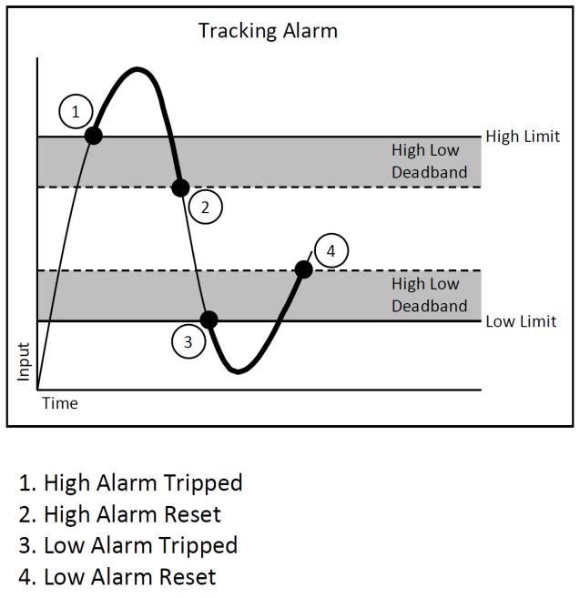


19 Figure 7: Alarm Parameters and Functionality Page 15 of 43
20 12.0 Setting and Monitoring Alarms Address Maps for each module are found at the end of this manual. An excerpt from the MAQ20- VDN module Address Map is shown below. Alarm parameters are stored in registers at addresses NOTE: When a module is registered in a system, addresses are offset by 2000 * R, where R is the Registration Number. Refer to Section 9.0 for further details on Registration Number. Start Address Read/ Write Number of Registers 700 R/W R/W R/W R/W 1 Address Range : Alarm Configuration Alarm Status, Low-Low Alarm Status, Low Alarm Status, High Alarm Status, High-High To clear a Latched alarm write a 0 to the corresponding channel bit. To clear a Latched alarm write a 0 to the corresponding channel bit. To clear a Latched alarm write a 0 to the corresponding channel bit. To clear a Latched alarm write a 0 to the corresponding channel bit. 704 R/W 1 Alarm Enable 1 = Enabled 0 = Disabled See below INT R/W 8 Alarm Configuration Alarm Configuration See below INT R/W 8 High Limit High Alarm Limit to 4095 INT R/W 8 Low Limit Low Alarm Limit to 4095 INT R/W 8 High Low DB Deadband for High Low Alarm to 4095 INT R/W 8 High-High Limit High-High Alarm Limit to 4095 INT R/W 8 Low-Low Limit Low-Low Alarm Limit to 4095 INT R/W 8 High-High Deadband for High-High Low-Low DB Low-Low Alarm to 4095 INT16 Alarms are configured by writing a code to the register at address * R and then enabled and disabled by writing a 1 or 0 to the register at address * R. Alarm Status is stored in registers at address range , offset by 2000 * R. The code written to address * R is the sum of a number representing the of alarm and a number representing the alarm limits to be monitored. Alarm Configuration Value = Alarm Type Code + Alarm Limit Code Alarm Type Code Alarm Limit Code Tracking 1000 Low Limit 100 Latching 2000 High Limit 200 High/Low Limit 300 Low-Low Limit 400 High/High Limit 500 All Limits 600 If the Alarm Configuration Value = 0, the Alarm is Off (Disabled). The Alarm for a given channel cannot be turned On (Enabled) until a valid, non-zero value is written to the Alarm Configuration register. Page 16 of 43
21 Example: A MAQ20-VDN module with serial number is installed in a system and has been assigned a Registration Number of 3. Set up the module to have a Tracking Alarm on Channel 1 with a High limit of 3000 counts, a Low limit of 500 counts and a Deadband of 100 counts. The MAQ20-VDN module with s/n has an address offset of 2000 * 3 = 6000 Write to register address = 6711 a value of = 1300 to set a Tracking Alarm with High Low limit Write to register address = 6731 a data value of 3000 to set the High limit Write to register address = 6751 a data value of 500 to set the Low limit Write to register address = 6711 a data value of 100 to set the Deadband for the High and Low limits Write to register address = 6704 the equivalent of bit code = 3 to enable Channel 1 When an alarm condition is reached as specified by the above parameters, the Alarm Status registers are written in response to the events and the red LED on the module is lit. Read register address = 6702 to view the status of the Low Alarm. If bit code = 3 is read, a Low Alarm has occurred on Channel 1. Read register address = 6703 to view the status of the High Alarm Page 17 of 43
22 13.0 Signal Averaging Signal averaging can be set on a per-channel basis by configuring the Average Weight. Average Weight is calculated as 2^x where x = 0 to 15 and the default value is x = 0. The running average is then calculated as follows: Average = Average + ((Sampled Value Average) / Average Weight) Address Maps for each module are found at the end of this manual. Excerpts from the MAQ20- VDN module Address Map are shown below. Signal averaging parameters are stored in registers at addresses NOTE: When a module is registered in a system, addresses are offset by 2000 * R, where R is the Registration Number. Refer to Section 9.0 for further details on Registration Number. Address Range : Module Configuration Start Read/ Number of Address Write Registers 120 R/W 8 AVG Weight Weight for AVG Calculation 0 to 15 INT16 Start Read/ Number of Address Write Registers Address Range : Module 1000 R 8 Channel for all 8 Channels to 4095 INT R 1 Alarm Status Status of Low-Low Alarm 1017 R 1 Alarm Status Status of Low Alarm 1018 R 1 Alarm Status Status of High Alarm 1019 R 1 Alarm Status Status of High-High Alarm 1030 R/W 8 Min Min for 8 Chan to 4095 INT R/W 8 Max Max for 8 Chan to 4095 INT R/W 8 Avg Average for 8 Chan to 4095 INT R 8 Channel 0 Last 8 readings for Channel to 4095 INT R 8 Channel 1 Last 8 readings for Channel to 4095 INT R 8 Channel 2 Last 8 readings for Channel to 4095 INT R 8 Channel 3 Last 8 readings for Channel to 4095 INT R 8 Channel 4 Last 8 readings for Channel to 4095 INT R 8 Channel 5 Last 8 readings for Channel to 4095 INT R 8 Channel 6 Last 8 readings for Channel to 4095 INT R 8 Channel 7 Last 8 readings for Channel to 4095 INT16 Example: A MAQ20-VDN module with serial number is installed in a system and has been assigned a Registration Number of 4. Set the Average Weight of Channel 4 to 8, then read the following parameters for Channel 4: Current, Min, Max, Average and the last 8 readings. The MAQ20-VDN module with s/n has an address offset of 2000 * 4 = 8000 Write to register address = 8124 a data value of 8 to set the Average Weight Read from register address = 9034 the min data from Channel 4 Read from register address = 9054 the max data from Channel 4 Read from register address = 9074 the average data from Channel 4 with weight 8 Read from register address to 1138 = the last 8 readings from Channel 4 Page 18 of 43
23 14.0 Reset Functions Two s of firmware reset are supported in the MAQ 20 I/O modules: Standard Reset is used to put the module in a user-defined state. The parameters listed below will be set to the last state saved to EEPROM. Parameters stored in EEPROM are not affected. Reset-to-Default reverts the module to the settings used at the factory during manufacture. It performs the standard reset actions plus resets most non-volatile parameters to default settings. Parameters stored in EEPROM are not affected. Table 3 shows what parameters are affected for each reset. Table 3: Parameters Affected by Standard Reset and Reset-to-Default RESET TYPE Standard Reset Reset-to-Default PARAMETERS Disables all Alarms Resets Min, Max and Average registers to 0 Clears all Status and Diagnostic registers All parameters listed under Standard Reset, plus: Clears all Alarm Limits and Deadbands Reset Registers Writing a valid data value to the Reset Register will force the module to perform a specified reset. Write 0 to perform Standard Reset and write 255 to perform Reset-to-Default. NOTE: The MAQ 20 I/O modules send a response to the reset register write before carrying out the reset. This means the module will be unresponsive to commands for approximately 3 seconds. Power-On-Reset (POR) and Brownout MAQ 20 I/O modules utilize a brown-out detect circuit and watchdog timer to ensure reliable and predictable operation under all conditions. Upon power cycle, brown-out detect or any extreme circumstance under which the watchdog timer expires, a Standard Reset is performed and parameters stored in EEPROM are loaded to the appropriate registers. Page 19 of 43
 and uniquely by their Serial Number printed on the side label (1234567-89).")
24 15.0 Module Identification and Status Registers Module identification including model number, serial number, date code and firmware revision are stored in registers at addresses I/O modules in a system are identified in general by their model number (MAQ20-VDN, MAQ20- JTC, etc.) and uniquely by their Serial Number printed on the side label ( ). When I/O modules are installed in the system, only a general identifier is visible on the front of the module (V, I, TC, etc.). Wire tags or additional labeling applied to the module terminal block may be used for visible unique identification in an installed system. Additionally, the system has a utility to provide a visible indication of module response for identification. Any write to address 98 plus the offset based on the Registration Number will blink the STATUS LED on the top angled surface of the module at a 5Hz rate for 5 seconds. For troubleshooting purposes, reset status, communications errors, and invalid data written to a module are monitored and made available to the user. Registers at addresses hold this information LED Indicators A set of 5 LEDs on the top panel of the MAQ 20 I/O modules indicate module power, operation, communication and alarm status. LED Function and Troubleshooting Tips: PWR Normal operation: BLUE, solid lit LED Off: Abnormal power situation Verify that a MAQ20-COMx is present in system Verify that the MAQ20-COMx module has 7-34VDC power connected and turned on Determine if the module is communicating by observing the TX and RX LEDs Page 20 of 43
25 STAT Normal operation: GREEN, 1 Hz blinking Module Detect: A write to the Module Detect Register will force this LED to blink at 5Hz rate for 5 seconds so the module location in a system can be visually identified. Referring to the Address Map, this register is at address 98 off of the module base address. LED Constant On or Constant Off: Abnormal operation Remove and reinstall module to force a reset Remove and reinstall module into another backbone position Determine if the module is communicating by observing the TX and RX LEDs RX, TX Normal Operation YELLOW, rapid blinking during communication with MAQ20-COMx module LED Constant Off: Abnormal operation or no communications to MAQ20-COMx module Verify communications by sending a request for data. Note that the fast communications rate used on the system backbone will result in the LED appearing dim due to short blinking cycle Verify that the PWR and STAT LED indicate normal operation Verify that there is only one MAQ20-COMx module installed in the system ALM Normal operation: Off Alarm Condition Detected: RED, solid lit. One or more alarms have been tripped. Read Alarm Registers based on Alarm Configuration to determine system status The following troubleshooting tips can be used to further diagnose and fix system problems: Remove and reinstall MAQ 20 I/O module and/or MAQ20-COMx module to verify proper insertion into Backbone Remove and reinstall MAQ 20 I/O module into another backbone position If a Backbone extension cable is used, ensure that the connections are made correctly Page 21 of 43
26 17.0 Specifications MAQ 20 VOLTAGE AND CURRENT INPUT MODULE Model Number MAQ20-MVDN MAQ20-VDN MAQ20-VSN MAQ20-IDN MAQ20-ISN Per Channel Setup Input Protection Continuous Transient CMV Channel-to-Bus CMR NMR Channel-to-Channel Transient Accuracy (1) Linearity / Conformity Resolution Stability Zero Span Bandwidth Scan Rate MAQ20-VSN, MAQ20-IDN, MAQ20-ISN MAQ20-MVDN, MAQ20-VDN Alarms Power Supply Current Dimensions (h)(w)(d) Environmental Operating Temperature Storage Temperature Typical at TA = +25 C and +24V system power Description 8-channel, millivolt, Differential Input ±50mV, ±100mV, ±250mV, ±1.0V, ±2.0V (Default ±1.0V) 8-channel, Volt, Differential Input ±5V, ±10V, ±20V, ±40V, ±60V (Default ±5V) 16-channel, Volt, Single-Ended Input ±5V, ±10V, ±20V, ±40V, ±60V (Default ±5V) 8-channel, milliamp, Differential Input 0-20mA, 4-20mA (Default 0-20mA) 16-channel, milliamp, Single-Ended Input 0-20mA, 4-20mA (Default 0-20mA) Individually configurable for range, alarms, averaging 240Vrms max (-VDN, -VSN, -IDN, -ISN) 150Vrms max (-MVDN) ANSI/IEEE C Vrms, 1 min ±28V peak (-VDN), ±3V peak (-MVDN, -IDN), 0V (-VSN, -ISN) ANSI/IEEE C /60 Hz 50/60 Hz ±0.035% span ±0.02% span 0.012% span ±15ppm/C ±35ppm/C 3Hz 200 Ch/s 20 Ch/s High / High-High / Low / Low-Low 30mA 4.51 x 0.60 x 3.26 (114.6mm x 15.3mm x 82.8mm) -40 C to +85 C -40 C to +85 C Relative Humidity 0 to 95%, non-condensing Emissions, EN ISM Group 1 Radiated, Conducted Class A Immunity EN ISM Group 1 RF ESD, EFT Certifications (1) Includes linearity/conformity, hysteresis and repeatability. Performance A +/- 0.5% Span Error Performance B Heavy Industrial CE, ATEX Pending UL Class I, Division 2, Groups A, B, C, D Pending Page 22 of 43
27 18.0 MAQ20-MVDN and MAQ20-VDN Address Map and Range Table Tables in this section outline the MAQ20-MVDN and MAQ20-VDN address space. in these registers contains all permanent and user settable information for module configuration, status, operation of all functions, data read/write, and data storage. Table columns list the following information: Start Address: Start address for the specified quantity of addresses. The start address is offset by 2000 * R where R is the module Registration Number. Read/Write: Indicates whether data at the address is Read, Write or both. Number of Registers: The number of 16 bit registers reserved for the specified contents. Contents: Parameter stored at the specified address. Description: Details, examples, limits, and default values for the parameter stored at the specified address. Range: Valid data read from or written to an address range. not in this range which is written to an address may return a Modus Exception 3, Illegal, or may be ignored. Type: The of data stored at the specified address. ASCII ABCDEFGHIJKLMNOPQRSTUVWXYZabcdefghijklmnopqrstuvwxyz, -, INT16 16 bit integer value, 0 to 65535, unless otherwise indicated. Stored at a single address. INT32 32 bit integer value, 0 to , unless otherwise indicated. Stored at two 16 bit addresses. MSB is stored at address N, LSB is stored at address N+1. Table 4: MAQ20-MVDN Address Map NOTE: When a module is registered in a system, addresses are offset by 2000 * R, where R is the Registration Number. Refer to Section 9.0 for further details on Registration Number. Start Address Read/ Write Number of Registers 0 R 15 Address Range 0-99 : Module Information Device Description MAQ20-MVDN MAQ20-VDN 19 R 11 Serial Number S Characters, Numbers, "-" and Space Characters, Numbers, "-" and Space ASCII ASCII 30 R 5 Date Code D1510 Characters, Numbers ASCII 35 R 5 Firmware Rev F1.00 Characters, Numbers and "." ASCII 40 R 1 Input Channels 8 Input Channels 8 ASCII 41 R 1 Output Channels 0 Output Channels 0 ASCII 98 W 1 Module Detect Any write will blink Status LED at 5Hz for 5 seconds 99 W 1 Reset Register 0 = Standard Reset, 255 = Reset to Default 0, 255 INT16 Page 23 of 43
28 Start Read/ Number of Address Write Registers Address Range : Module Configuration 100 R/W 8 Input Range Range for each of 8 channels See Table 5 INT W 1 Save to EEPROM 0 = Gain, Avg Weight, Scan List 0 INT R/W 8 AVG Weight Weight for AVG Calculation 0 to 15 INT R/W 8 Channel Enable 0 = Disable 1 = Enable (default) 0 or 1 INT16 Start Read/ Address Write Number of Registers 700 R/W R/W R/W R/W 1 Address Range : Alarm Configuration Alarm Status, Low-Low Alarm Status, Low Alarm Status, High Alarm Status, High-High To clear a Latched alarm write a 0 to the corresponding channel bit. To clear a Latched alarm write a 0 to the corresponding channel bit. To clear a Latched alarm write a 0 to the corresponding channel bit. To clear a Latched alarm write a 0 to the corresponding channel bit. 704 R/W 1 Alarm Enable 1 = Enabled 0 = Disabled See Section 12.0 INT R/W 8 Alarm Configuration Alarm Configuration See Section 12.0 INT R/W 8 High Limit High Alarm Limit to 4095 INT R/W 8 Low Limit Low Alarm Limit to 4095 INT R/W 8 High Low DB Deadband for High Low Alarm to 4095 INT R/W 8 High-High Limit High-High Alarm Limit to 4095 INT R/W 8 Low-Low Limit Low-Low Alarm Limit to 4095 INT R/W 8 High-High Deadband for High-High Low-Low DB Low-Low Alarm to 4095 INT16 Start Read/ Address Write Number of Registers Address Range : Module 1000 R 8 Channel for each of 8 Channels to 4095 INT R 1 Alarm Status Status of Low-Low Alarm 1017 R 1 Alarm Status Status of Low Alarm 1018 R 1 Alarm Status Status of High Alarm 1019 R 1 Alarm Status Status of High-High Alarm 1030 R/W 8 Min Min for 8 Chan to 4095 INT R/W 8 Max Max for 8 Chan to 4095 INT R/W 8 Avg Average for 8 Chan to 4095 INT R 8 Channel 0 Last 8 readings for Channel to 4095 INT R 8 Channel 1 Last 8 readings for Channel to 4095 INT R 8 Channel 2 Last 8 readings for Channel to 4095 INT R 8 Channel 3 Last 8 readings for Channel to 4095 INT R 8 Channel 4 Last 8 readings for Channel to 4095 INT R 8 Channel 5 Last 8 readings for Channel to 4095 INT16 Page 24 of 43
MAQ 20. Industrial Data Acquisition and Control System MA1040. MAQ20-COM2 MAQ20-COM4 Hardware User Manual
 MAQ 20 Industrial Data Acquisition and Control System MA1040 MAQ20-COM2 MAQ20-COM4 Hardware User Manual MAQ20-COM2/-COM4 Hardware User Manual MA1040 Rev. B January 2014 2014 Dataforth Corporation. All
Rugged Precision The MAQ 20 Industrial Data Acquisition & Control System 2014 Product Catalog
 High Performance Industrial Signal Conditioning, Data Acquisition & Control, and Data Communication Products Since 1984 WORLD HEADQUARTERS Dataforth Corporation 3331 E. Hemisphere Loop Tucson, AZ 85706
Industrial Data Acquisition and Control System MA1039 MAQ20 LabVIEW VI User Manual
 MAQ 20 Industrial Data Acquisition and Control System MA1039 MAQ20 LabVIEW VI User Manual MAQ20 LabVIEW VI User Manual MA1039 Rev. A April 2015 2015 Dataforth Corporation. All Rights Reserved. ISO9001:2008-Registered
8B SLX300 Data Acquisition System
 8B SLX300 Data Acquisition System Description Dataforth s newest data acquisition system builds on the proven reliability of the SLX200 SCM5B-based system and also takes advantage of the miniature size
SLX200 LabVIEW VI Library User Manual
 SLX200 LabVIEW VI Library User Manual isolynx SLX200 LabVIEW VI Library Manual isolynx SLX200 LabVIEW VI Library User Manual MA1028 Rev. A March 2007 The information in this manual has been checked carefully
SCM5B. SLX200 Data Acquisition System. isolynx. Data Acquisition Systems. Visit our website Features
 Data Acquisition Systems SCM5B SLX200 Data Acquisition System Features Modbus RTU Support on RS-232 and RS-485 Modbus TCP Support (optional) 240VAC Continuous Analog Input Protection Channel-to-Channel
MAQ 20 Industrial Data Acquisition and Control System ReDAQ Shape for MAQ 20 User Manual
 MAQ 20 Industrial Data Acquisition and Control System ReDAQ Shape for MAQ 20 User Manual 1 MAQ 20 Industrial Data Acquisition and Control System ReDAQ Shape for MAQ 20 User Manual MA1038 Rev. B May 2012
OBSOLETE. Isolated, Linearized, Thermocouple Input 3B47 FEATURES APPLICATIONS PRODUCT OVERVIEW FUNCTIONAL BLOCK DIAGRAM
 FEATURES Interfaces, amplifies, filters, isolates, & linearizes analog input voltages from a J, K, T, E, R, S or B-type thermocouple Thermocouple input signal is internally linearized High accuracy internal
Isolated, Field Configurable Analog Input 6B11 / 6B11HV FEATURES APPLICATIONS PRODUCT OVERVIEW
 Isolated, Field Configurable Analog Input 6B11 / 6B11HV FEATURES Single-channel isolated signal-conditioning modules. Accepts outputs from Thermocouple, millivolt, volt and current signals. Complete microcomputer-based
PACSystems* RX3i IC694ALG232
 November 2015 PACSystems* RX3i IC694ALG232 Advanced Diagnostics 16 Channel Input Analog Voltage Module The PACSystems* RX3i 16-Channel Analog Voltage Input module provides 16 single-ended or 8 differential
USB-2001-TC. USB-based Thermocouple Input. User's Guide
 USB-2001-TC USB-based Thermocouple Input User's Guide Document Revision 6A November 2014 Copyright 2014 Trademark and Copyright Information Measurement Computing Corporation, InstaCal, Universal Library,
Isolated Wideband Voltage Input 3B40 / 3B41 FEATURES APPLICATIONS PRODUCT OVERVIEW FUNCTIONAL BLOCK DIAGRAM
 Isolated Wideband Voltage Input 3B40 / 3B41 FEATURES Interfaces, amplifies, protects& filters wide-bandwidth (h0 khz) single-channel analog voltage inputs. Module provides simultaneous precision voltage
45SD Series Bus Expansion Cards For use with Q45X Series Photoelectric Sensors on SDS Bus Networks
 45SD Series Bus Expansion Cards For use with Series Photoelectric Sensors on SDS Bus Networks Banner model 45SD plug-in bus cards enable a Banner Series sensor to establish a logical relationship between
Isolated Voltage Input 3B30 / 3B31 FEATURES APPLICATIONS PRODUCT OVERVIEW FUNCTIONAL BLOCK DIAGRAM
 Isolated Voltage Input 3B30 / 3B31 FEATURES Interfaces, amplifies, & filtersanalog input voltages. Narrow-bandwidth (3Hz) single-channel single conditioning. Module provides simultaneous precision voltage
Isolated Linearized RTD Input 5B34 FEATURES APPLICATIONS PRODUCT OVERVIEW FUNCTIONAL BLOCK DIAGRAM
 Isolated Linearized RTD Input 5B34 FEATURES Amplifies, Protects, Filters, and Isolates Analog Input. Linearize a wide variety of 2 & 3 wire RTDs. (True 4-wire RTD measurements are provided by the 5B35).
M.A.L PlugIn Dataforth MAQ20 V technikmedia
 technikmedia User Manual M.A.L PlugIn Dataforth MAQ20 V01.01.01.0002 technikmedia Ingenieurbüro für technische Medien Dipl.-Ing. Dietmar Neumann Am Homberg 13 B D-45529 Hattingen Tel.: +49 2324 34 44 792
Isolated, Voltage or Current Input 7B30 FEATURES APPLICATIONS PRODUCT OVERVIEW FUNCTIONAL BLOCK DIAGRAM
 Isolated, Voltage or Current Input 7B30 FEATURES Interfaces, amplifies and filters unipolar and bipolar millivolt and voltage inputs. Provides a protected precision output of either +1 V to +5 V or 0 V
PACSystems* RX3i IC694ALG233
 November 2015 PACSystems* RX3i IC694ALG233 Advanced Diagnostics Analog Current Input Module 16 Channel The PACSystems* RX3i 16-Channel Analog Current Input module provides 16 single-ended input channels.
Isolated Voltage Input 7B31 FEATURES APPLICATIONS PRODUCT OVERVIEW FUNCTIONAL BLOCK DIAGRAM
 Isolated Voltage Input 7B31 FEATURES Interfaces, amplifies, and filters unipolar and bipolar voltage inputs. Module provides a precision output of either +1 V to +5 V or 0 V to +10 V, linear with temperature.
Isolated Process Current Output 3B39 FEATURES APPLICATIONS PRODUCT OVERVIEW FUNCTIONAL BLOCK DIAGRAM
 Isolated Process Current Output 3B39 FEATURES Interfaces, isolates, & filters a 0 to +10V or -10V to +10V input signal and provides an isolated process current output across loads of 0 to 850Ω.. Intended
Isolated, Process Current Output 7B39 FEATURES APPLICATIONS PRODUCT OVERVIEW FUNCTIONAL BLOCK DIAGRAM
 Isolated, Process Current Output 7B39 FEATURES Interfaces, isolates and filters a 0 V to + 10 V or +1 V to +5 V input signal. Provides an isolated process current output of 0 ma to 20 ma or 4 ma to 20
ioselect Z-NET Z-SG Bridge Input Isolating I/O Module
 -wire Bridge Connection Excitation for to 30 Ω Load Cells 00 Volt (3-way) Isolation Excellent Accuracy (0.0%) DIP Switch Configuration Digital Input Tare Calibration RS8 Modbus RTU Superior Flexible Power:
Isolated, Voltage or Current Input 7B41 FEATURES APPLICATIONS PRODUCT OVERVIEW FUNCTIONAL BLOCK DIAGRAM
 Isolated, Voltage or Current Input 7B41 FEATURES Interfaces, amplifies and filters unipolar and bipolar voltage inputs. Module provides a precision output of either +1 V to +5 V or 0 V to +10 V. All 7B41
Isolated Current Output 5B39 FEATURES APPLICATIONS PRODUCT OVERVIEW
 Isolated Current Output 5B39 FEATURES Converts a High-level analog input voltage into a floating proportional output current. Output current of 4 to 20 ma or 0 to 20 ma across loads from 0Ω to 750Ω. High
PACSystems* RX3i and Series 90*-30 IC694ALG442-CC and IC693ALG442-EC
 January 214 MODULE K USER SUPPLY IC694ALG442 I1 I2 I3 I4 Q1 Q2 PACSystems* RX3i and Series 9*-3 IC694ALG442-CC and IC693ALG442-EC Analog Module, 4 Inputs/2 Outputs, Current/Voltage Analog Current/Voltage
/8 DIN Universal Process Indicator
 Data Sheet SS/_ High visibility LED display the clearest view of your process status.% measurement accuracy precise indication of process measurement Analog and relay outputs as standard alarm and retransmission
Gateway 1400 Reference Manual
 Profibus-DP Gateway 1400 Reference Manual Copyright All Rights Reserved. No part of this document may be copied, reproduced, republished, uploaded, posted, transmitted, distributed, stored in or introduced
Precision Voltage Measurement. Instruments. Applications. Voltage Inputs. High-Stability, Low Drift Voltage References. Key Design Features
 VOLTpoint Precision Voltage Measurement Instruments Precision Voltage Measurement VOLTpoint is a family of precision instruments designed for measuring a wide range of voltage inputs; ideally suited for
Isolated Process Current Input with Loop Power 7B35
 Isolated Process Current Input with Loop Power 7B35 FEATURES Single-channel signal conditioning current input module that interfaces with two-wire transmitters. Module provides a precision output of either
Installation and User Guide
 D5 Installation and User Guide 8-Channel DALI Controller (478) Introduction The 478 is for controlling DALI ballasts, drivers and load interface units (except for the 490 Blinds Controller). Do not connect
Isolated Process Current Input 7B32 FEATURES APPLICATIONS PRODUCT OVERVIEW FUNCTIONAL BLOCK DIAGRAM
 Isolated Process Current Input 7B32 FEATURES Interfaces, amplifies and filters a process-current input. Module provides a precision output of either +1 V to +5 V or 0 V to +10 V, linear with temperature.
8B SLX300 LabVIEW VI Examples User Manual
 8B SLX300 LabVIEW VI Examples User Manual 8B isolynx SLX300 LabVIEW VI Examples User Manual MA1033 Rev. A July 2010 2010 Dataforth Corporation. All Rights Reserved. The information in this manual has been
100mm Process Indicator Recorder
 Data Sheet SS/_3 100mm Process Indicator Recorder One or two pen continuous line 100mm recorder universal input for thermocouple, RTD, mv, ma and V Clear, 5-digit LED display high visibility, wide viewing
895/896M Frequency Output Math Modules
 895/896M Frequency Output Math Modules Application Example Both models are designed for integrator/totalizer applications. The 896M is ideal for demand metering applications. With one high speed pulse
Table of Contents. Introduction... 2 Description...2 Specifications...3 Installation.. 5 Calibration.. 6 General Maintenance...7
 User's Manual: Series 330I Model 330I DC-Powered Three-Way Isolator Table of Contents Page Introduction... 2 Description....2 Specifications....3 Installation.. 5 Calibration.. 6 General Maintenance...7
PACSystems* RX3i and Series 90*-30 IC694ALG223 and IC693ALG223
 May 2014 PACSystems* RX3i and Series 90*-30 IC694ALG223 and IC693ALG223 Analog Current Input Module 16 Channel The PACSystems* RX3i/Series 90* 16-Channel Analog Current Input module provides 16 single-ended
Ultra-Accurate Temperature Measurement Instruments
 TEMPpoint Temperature Measurement Instruments Ultra-Accurate Temperature Measurement Instruments TEMPpoint is a series of precision temperature measurement instruments designed for high accuracy and industrial
Wide Bandwidth Strain Gage Input 3B18 FEATURES APPLICATIONS PRODUCT OVERVIEW FUNCTIONAL BLOCK DIAGRAM
 Wide Bandwidth Strain Gage Input 3B18 FEATURES Wideband (20 khz) single-channel signal conditioning module. Module Bandwidth is user-selectable between 20 khz and 100Hz, with user-supplied filter caps
D7000 SERIES MODBUS TCP/IP ETHERNET INTERFACE MODULES
 11/17 D7000 SERIES MODBUS TCP/IP ETHERNET INTERFACE MODULES D7000 FEATURES Complete data acquisition systems. Analog and Digital I/O models available. RJ-45 Ethernet 10/100MB interface. Modbus TCP/IP Ethernet
TC Type Range Conformity Error. J -210 C to +760 C (-347 F to F) ±0.09 C (±0.16 F) K -244 C to C (-408 F to F) ±0.1 C (±0.
 ±0.09 C (±0.16 F) K -244 C to C (-408 F to F) ±0.1 C (±0.") LAUREL ELECTRONICS, INC. Laureate Thermocouple Panel Meter / Controller Features Factory calibrated for thermocouple types J, K, T, E, N, R, S Entire range of each thermocouple in one scale Highly accurate
LAUREL ELECTRONICS, INC. Laureate Thermocouple Panel Meter / Controller Features Factory calibrated for thermocouple types J, K, T, E, N, R, S Entire range of each thermocouple in one scale Highly accurate
UniPak UP448 Bridge Input Isolating Signal Conditioner
 6-wire Bridge Connection Excitation for to 350 Ω Load Cells 500 Volt (3-way) Isolation Excellent Accuracy (0.0%) DIP Switch Configuration Digital Input Tare Calibration RS85 Modbus RTU Superior Flexible
microblox I/O Modules w/ Bluetooth Wireless Technology Introduction to the microblox Module Family
 microblox I/O Modules w/ Bluetooth Wireless Technology Introduction to the microblox Module Family The microblox (ub) family of analog I/O modules and back-panel carriers offer a modern and flexible space-saving
WIRELESS SERIES Single or Dual Axis MEMS Inclinometer
 The 2GIG Industrial RF Wireless Inclinometer is engineered to work for all applications. The internal software provides unlimited programming capabilities. It offers the best operating temperature range,
Valve and Case Expansion Monitor Specifications
 Valve and Case Expansion Monitor Specifications The Valve and Case Expansion Monitor is designed for high reliability for the plant s most critical rotating machinery. This 1-slot monitor is used together
Tempco Instruction Manual
 Tempco Instruction Manual 1/16 DIN Solid State Temperature Controller Relay Output Solid State Output For Heating Model Numbers: TEC-901, TEC-902, TEC-905 Temperature controls in this series are designed
I/O SIGNAL CONDITIONER
 Technical Data Sheet No. TD9809M Rev. F Date of Issue: December 9, 2009 OPERATING MANUAL I/O SIGNAL CONDITIONER CAUTION: THIS PRODUCT DOES NOT PROVIDE GALVANIC ISOLATION. DO NOT ATTEMPT USE OF THIS PRODUCT
The PM1000 series is a universal 4 digit LED plug-on display for transmitters with 4-20mA 2 wire output and fitted with DIN43650 connector.
 PM1000 SERIES PLUG-ON DISPLAY BRIGHT LED DISPLAY INDICATION RANGE -999 TO +9999 FITS TO DIN 43650 CONNECTOR PLUG-ON TO ANY TRANSMITTER WITH 4-20MA OUTPUT EASY TO SCALE ON SITE ROBUST DESIGN SET POINT OPTION
Product Specifications
 Product Specifications VIBROCONTROL 6000 Monitoring System Description of Functionality Overview The VIBROCONTROL 6000 Monitoring System is used for both stand-alone machine protection and condition monitoring
Installation Instructions
 Installation Instructions (Cat. No. 1794-TBN) 6 1 5 9 4 2 3 10 6 7 8 Component Identification 1 Female flexbus connector 2 Terminal base unit (1794-TBN) 3 Male flexbus connector 4 Keyswitch Set to the
VL BPC MINI. A configurable industrial computer platform Intel Atom Z510PT CMAT IPC Module Option [I28] AUTOMATION Data Sheet 2930_en_A.
![VL BPC MINI. A configurable industrial computer platform Intel Atom Z510PT CMAT IPC Module Option [I28] AUTOMATION Data Sheet 2930_en_A.](/thumbs/72/66783612.jpg "VL BPC MINI. A configurable industrial computer platform Intel Atom Z510PT CMAT IPC Module Option [I28] AUTOMATION Data Sheet 2930_en_A.") A configurable industrial computer platform Intel Atom Z0PT CMAT IPC Module Option [I8] AUTOMATION Data Sheet 90_en_A Description PHOENIX CONTACT 0-0-0 Features The VL BPC MINI is an embedded box PC and
A configurable industrial computer platform Intel Atom Z0PT CMAT IPC Module Option [I8] AUTOMATION Data Sheet 90_en_A Description PHOENIX CONTACT 0-0-0 Features The VL BPC MINI is an embedded box PC and
Ultra-Accurate Measurement for Temperature and Voltage
 Ultra-Accurate Measurement for Temperature and Voltage MEASURpoint is an ultra-accurate instrument for measuring any combination of thermocouple, RTD, and voltage inputs. MEASURpoint is available as a
VL BPC MINI. A configurable industrial computer platform. Data sheet 2930_en_F. 1 Description. 2 Features
 A configurable industrial computer platform Data sheet 90_en_F Description PHOENIX CONTACT 0-08- Features The VL BPC MINI is an embedded box PC and is part of the Valueline family of industrial computers.
UDC 1000 and UDC 1500 MICRO-PRO SERIES UNIVERSAL DIGITAL CONTROLLERS
 UDC 1000 and UDC 1500 MICRO-PRO SERIES UNIVERSAL DIGITAL CONTROLLERS EN0I-6041 12/99 PRODUCT SPECIFICATION SHEET OVERVIEW The UDC 1000 and UDC 1500 are microprocessor-based 1/16 DIN and 1/8 DIN controllers
RS-485 I/O Modules: ADAM-4000
 RS-485 I/O Modules: ADAM-4000 23 ADAM-4000 Series Overview ADAM-4000 Series Remote Data Acquisition and Control Modules Overview 23-2 and Controller Module Selection Guide 23-4 I/O Module Selection Guide
Wall-/Pipe Mounted Universal Process Indicator
 Data Sheet SS/_8 Wall-/Pipe Mounted Universal Process Indicator High visibility LED display the clearest view of your process status 0.1% measurement accuracy precise indication of process measurement
Shown with terminal block Supports diagnostic point fault contacts in the logic program
 GFK-2482F PACSystems* RX3i Isolated Analog Input Modules, IC695ALG106-EA, IC695ALG112-EA Product Description Isolated Analog Voltage/Current Input module IC695ALG106 provides 6 isolated input channels.
Ultra-Accurate Measurement for Temperature and Voltage
 Ultra-Accurate Measurement for Temperature and Voltage MEASURpoint is an ultra-accurate instrument for measuring any combination of thermocouple, RTD, and voltage inputs. MEASURpoint is available as a
MINI-PS AC/10-15DC/8
 Primary-Switched Power Supply, Narrow Design Data Sheet 08/2004 MINI POWER provides: An extra narrow design, with widths of 22.5 mm, 45 mm, and 67.5 mm (0.886, 1.772, and 2.657 in.) Global use due to a
Analog Input, 16-Bit Thermocouple Module
 Analog Input, 16-Bit Module Product Description The Analog Input Module is an intelligent module that accepts seven independent thermocouple or millivolt inputs. The module receives power from the backplane
Installation Instructions
 Installation Instructions (Cat. No. 1794-PS1) 1 2 3 4 5 7 6 Component Identification 1 Supply module 1794-PS1 2 Indicator 3 120/230V ac ground 4 120/230V ac common L2/N connections 5 120/230V ac power
Rhino Buffer Module PSM24-BFM600S. Operating Instructions
 Rhino Buffer Module PSM24-BFM600S Operating Instructions RHINO BUFFER MODULE PSM24-BFM600S Description The PSM24-BFM600S Buffer Module will hold the output voltage of a 24 VDC power supply after brownouts
/8 DIN Motorized Valve Controller
 Data Sheet SS/_5 Boundless motorized valve controller no need for slidewire feedback; improves reliability Two sealed 5A control relays suitable for direct connection to the valve, reducing installation
NBF-3. User Manual. NMEA 0183 Buffer. For all variants: NBF-3-BAS, Rev A. Issue 1.01
 NBF-3 NMEA 0183 Buffer User Manual For all variants: NBF-3-BAS, Rev A Issue 1.01 NMEA 0183 Buffer - NBF-3 Contents Company Information 4 Important Notices 5 Trademarks and Registered Trademarks 5 Fair
Rhino Redundancy Module PSM24-REM360S. Operating Instructions
 Rhino Redundancy Module PSM4-REM360S Operating Instructions RHINO REDUNDANCY MODULE PSM4-REM360S Description With this module and two power supplies of the PSM series (78, 90, 56, 80 and 360 watt models),
FLEX Ex Spring Clamp Terminal Base
 Installation Instructions FLEX Ex Spring Clamp Terminal Base (Cat. No. 1797-TB3S) 1 10 11 4 Only remove this cover plug if connecting another terminal base unit. 3 5 6 12 2 7 8 9 41253 Component Identification
ABB Instrumentation. Specification DataFile COMMANDER 100. the-easy-to use 1. /8 DIN controller with extensive application capabilities
 COMMANDER Universal Process Controller Specification DataFile PID controller with one shot autotune single loop, heat/cool and ramp/soak as standard Quick code, front face or PC configuration easy commissioning
MODEL CIO-EN MODBUS/TCP, MODBUS/RTU I/O MODULE
 INSTALLATION INSTRUCTIONS Revision B1 Rapid City, SD, USA, 05/2009 MODEL CIO-EN MODBUS/TCP, MODBUS/RTU I/O MODULE BE SURE POWER IS DISCONNECTED PRIOR TO INSTALLATION! FOLLOW NATIONAL, STATE AND LOCAL CODES.
TRACKER 240 SERIES. Load Cell and Weighing Indicators. A Precision Measurement Instrument with Outstanding Features
 TRACKER 240 SERIES Load Cell and Weighing Indicators A Precision Measurement Instrument with Outstanding Features TRACKER 240 SERIES INDICATORS Ratiometric Measurement Tare and Auto Transducer Excitation
DI-924MB. Thermocouple/Millivolt Input Module
 Multi-Channel Temperature Control Modules Thermocouple or Millivolt Input Limit Alarms or Discrete Outputs Models DI-924MB: 4 input channels Input Four input channels: Thermocouple (types J, K, T, R, S,
DTM Distributed Transmitter Monitor
 Distributed Transmitter Monitor 96 Communication Module The 96 functions as an RS232 to RS485 convertor and / or enables (32) modules to be networked together via Modbus. Combined with the -CFG configuration
TRC-190 User s Manual
 User s Manual Edition 3.2, May 2017 www.moxa.com/product 2017 Moxa Inc. All rights reserved. User s Manual The software described in this manual is furnished under a license agreement and may be used only
5450 NW 33rd Ave, Suite 104 Fort Lauderdale, FL Fruitland Ave Los Angeles, CA SST7000 SST7100. Speed Switch / Transmitter
 5450 NW 33rd Ave, Suite 104 Fort Lauderdale, FL 33309 3211 Fruitland Ave Los Angeles, CA 90058 SST7000 SST7100 Speed Switch / Transmitter Installation and Operation Manual Rev. C P/N145F-13112 PCO 00009270
SLIMCON-6 24V DC POWERED ISOLATING SIGNAL CONVERTER
 SLIMCON-6 24V DC POWERED ISOLATING SIGNAL CONVERTER Whilst every effort has been taken to ensure the accuracy of this document, we accept no responsibility for damage, injury, loss or expense resulting
VersaMax* Analog Input, 16-Bit Thermocouple Module
 VersaMax* Analog Input, 16-Bit Module Product Description The Analog Input Module is an intelligent module that accepts seven independent thermocouple or millivolt inputs. The module receives power from
MICRO SERIES PROCESS DISPLAYS LARGE DIGIT MODELS
 The MICRO SERIES PROCESS DISPLAYS LARGE DIGIT MODELS Mighty-5 DPM MODELS Micro-P & Mighty-1 Mighty-1 Micro-P ELECTRO-NUMERICS, INC. Introduction The Electro-Numerics family of Digital Panel Meters and
HIT/HIX HART Isolator
 / Isolator December 2017 Description Moore Industries Isolators provide highly economical solutions to common and costly problems that plague many of today s smart process loops. Protect and enhance your
Analog Voltage Combination Module
 Analog Voltage Combination Module T1F-8AD4DA-2 8-channel analog voltage input 4-channel analog voltage output The combination 8-in and 4-out voltage module uses a T1K-8B or T1K-8B-1 base, which is purchased
USB to RS232 Converter USB-013 (Rev3) User s Manual Ver. 1.2 HuMANDATA LTD.
 User s Manual Ver. 1.2 HuMANDATA LTD.") USB to RS232 Converter USB-013 (Rev3) User s Manual Ver. 1.2 HuMANDATA LTD. Table of Contents Precautions... 1 Revision History... 2 Introduction... 2 1. Overview... 3 2. Power Supply... 3 3. Specifications...
USB to RS232 Converter USB-013 (Rev3) User s Manual Ver. 1.2 HuMANDATA LTD. Table of Contents Precautions... 1 Revision History... 2 Introduction... 2 1. Overview... 3 2. Power Supply... 3 3. Specifications...
5450 NW 33rd Ave, Suite 104 Fort Lauderdale, FL Fruitland Ave Los Angeles, CA UM Channel Monitor.
 5450 NW 33rd Ave, Suite 104 Fort Lauderdale, FL 33309 3211 Fruitland Ave Los Angeles, CA 90058 UM-600 6-Channel Monitor Version 2 Installation and Operation Manual Rev. G P/N145F-12990 PCO 00007462 (c)
Kinetix 300 Memory Module Programmer
 Kinetix 300 Memory Module Programmer Catalog Number 2097-PGMR Topic About the Memory Module Programmer 1 Parts List 3 Batteries Operation 4 Using Memory Module Programmer 6 Switch On/Off Memory Module
VIBRATION MONITOR CX-RLY
 VIBRATION MONITOR CX-RLY MaintTech Norrkoping Airport Sweden Email: mainttech@live.se Website: www.mainttech.se 1 CX-RLY-C MODULE Version 1 1 Important User Information Solid-state equipment has operational
Industrial Power Supplies
 50-600 Watt Features Switch mode power supplies for DIN-rail mounting 6 power ranges with 2, 3, 6, 12, 20 and 24 A output current (24 VDC models) Selectable 115/ 230 VAC input Very low ripple and noise
TM221ME16T controller M IO transistor PNP Ethernet
 Characteristics controller M221 16 IO transistor PNP Ethernet Main Range of product Product or component type [Us] rated supply voltage Discrete input number Analogue input number Discrete output type
TM221M16TG controller M IO transistor PNP spring
 Characteristics controller M221 16 IO transistor PNP spring Main Range of product Product or component type [Us] rated supply voltage Discrete input number Analogue input number Discrete output type Discrete
Strain Gauge Converter
 EN Z-SG General Description Module Z-SG is a strain gauge signal converter. Measurements taken using the 6-wires or 4-wires technique are available through Modbus-RTU serial protocol or the analog output.
LAUREL. Laureate Digital Panel Meter for Load Cell & Microvolt Input ELECTRONICS, INC. Features. Description
 Description LAUREL ELECTRONICS, INC. Features Laureate Digital Panel Meter for Load Cell & Microvolt Input 20, 50, 100, 250 & 500 mv ranges Span adjust from 0 to ±99,999, zero adjust from -99,999 to +99,999
CompactBlock Guard I/O EtherNet/IP Safety Modules
 Installation Instructions CompactBlock Guard I/O EtherNet/IP Safety Modules Catalog Numbers 1791ES-IB8XOBV4, 1791ES-IB16 Topic Page Important User Information 2 North American Hazardous Location Approval
TM221CE40R controller M IO relay Ethernet
 Characteristics controller M221 40 IO relay Ethernet Main Range of product Product or component type [Us] rated supply voltage Jan 6, 2019 Modicon M221 Logic controller 100...240 V AC Discrete input number
ACTIONI/Q Q498. DC Powered DC Input Field Configurable Isolator with Math Functions
 ACTIONI/Q Q498 DC Powered DC Input Field Configurable Isolator with Math Functions Q498-0000 Provides 2 Isolated Analog Inputs, 1 Analog Output & 1 Frequency Output, as well as a Discrete Input & Output
Voltage Current Front-mounting bracket
 Switching Power Supply S8PS Compact DIN-Rail Mounting Industrial Power Supplies with Capacities Up to 600 W Models range from 0 W to 600 W. Universal input: voltage range 0 to 240 VAC. Power Factor Correction
C160 Wall-/Pipe Mounted Universal Process Indicator
 Data sheet DS/ EN Rev. I Wall-/Pipe Mounted Universal Process Indicator reliable process indicator, wherever it s needed High visibility LED display the clearest view of your process status 0.1% measurement
REDUNDANCY MODULE TSP-REM360 AND TSP-REM600
 REDUNDANCY MODULE TSP-REM360 AND TSP-REM600 Operating Instructions Seite 1 Dimensions drawings: TSP-REM360 Weight: 0.882lb Gewicht: 0.40kg Seite 2 Dimensions drawings: TSP-REM600 Bottom view Top view Side
RSTI-EP Slice I/O. Analog Input Modules `EP-3164, EP-3264, EP-3124, EP-3368, EP-3468 EP-3664, EP-3704, EP GFK-2960F September 2018
 September 2018 Module Status LED Channel Status LEDs Digital Input Connector Ground 24 V DC FE Analog Input Module RSTI-EP Slice I/O Analog Input Modules `EP-3164, EP-3264, EP-3124, EP-3368, EP-3468 EP-3664,
TM221CE24T controller M IO transistor PNP Ethernet
 Characteristics controller M221 24 IO transistor PNP Ethernet Main Range of product Product or component type [Us] rated supply voltage Discrete input number Analogue input number Discrete output type
Intech Micro 2300-A8VI analogue input station MODBUS RTU slave application supplementary manual.
 Intech Micro 2300-A8VI analogue input station MODBUS RTU slave application supplementary manual. MODBUS supplementary manual to the 2300-A8VI Installation Guide. The 2300 series stations are designed to
DI-917MB/DI-918MB. Heavy-duty 1A solid-state relays provide dependable on/off control of industrial devices. Analog Output Module. Four Analog Outputs
 Multi-Channel Analog Output Modules DC Current or DC Voltage Outputs Discrete Outputs DI-917MB/DI-918MB Models DI-917MB: 4 current output channels DI-918MB: 4 voltage output channels Analog Output DI-917MB:
8 Channel Analog Input Module Datasheet. Address / Baud rate / range configurable by the user
 8 Channel Analog Input Module Datasheet User s Manual Overview: DAM module is a new generation data acquisition and control system based on modular embedded systems. Adopting standard DIN35 rail mounting
6-Channel Monitor. Installation and Operation Manual
 3211 Fruitland Ave Los Angeles, CA 90058 Catalyst Monitor 6-Channel Monitor Version 2 Installation and Operation Manual Rev. H P/N145F-12964 PCO - 00009743 (c) Copyright 2015, Barksdale, Inc. All Rights
USB-201-OEM. Analog and Digital I/O. User's Guide
 USB-201-OEM Analog and Digital I/O User's Guide Document Revision 7A December 2014 Copyright 2014 Trademark and Copyright Information Measurement Computing Corporation, InstaCal, Universal Library, and
This Datasheet for the IC670ALG310. Analog Output Voltage, 8 Channel, +/-10V, 0 to 10V.
 This Datasheet for the IC670ALG310 Analog Output Voltage, 8 Channel, +/-10V, 0 to 10V http://www.qualitrol.com/shop/p-14493-ic670alg310.aspx Provides the wiring diagrams and installation guidelines for