Smart Professional Surveillance System User s Manual
|
|
|
- Jessie Patrick
- 6 years ago
- Views:
Transcription
1 Smart Professional Surveillance System User s Manual Version
2 Table of Contents 1. OVERVIEW AND ENVIRONMENT Overview Performance Environments INSTALLATION AND UPGRADE Installation Un-installation SETTING Login Interface Homepage General File Path Alarm Version Account Add role Add user Device Manager Device CFG General Network Remote Encode Image PTZ Control Event Video Detect Alarm Abnormality Smart Config Record/Storage Schedule i
3 Disk Maintenance Account Maintenance WEB Alarm Setup Set Alarm Scheme Enable/Disable/Export Scheme Tour &Task PC-NVR Video Wall Configuration BASIC OPERATION Liveview Real-time Liveview Record Snapshot E-Map Edit E-Map Preview E-Map Fisheye Smart Alarm Smart Track PTZ Preset Tour Pan Scan Pattern Aux Playback Playback Device Record Playback Local Record Export Fisheye Playback Alarm Manager Video Talk VTS Center Monitor Talk ii
4 4.4.4 Announcement Info Search Issue Card Access Console Organizations/Zones List/View Event User Management Department Management User Management Permission Management Door Group Right User Right First Card Unlock Multi-door Lock Anti-pass Back Inter-door Lock Remote Verification Period Setup Holiday Setup Event Configuration Log Attendance Attendance User Shift Report Search EXTENSION Video Wall Data Report Log iii
5 Welcome Thank you for using our Smart Professional Surveillance System (SmartPSS)! This user s manual is designed to be a reference tool for operation of your system. Here you can find detailed operation information about SmartPSS. iv
6 1. Overview and Environment 1.1 Overview SmartPSS is an abbreviation for Smart Professional Surveillance System. The software is to manage small quantity security surveillance devices. It releases with the device and does not support the products from other manufacturers. It has the following features: View real-time video of several camera channels. View the playback video files from various cameras. Support multiple scheduled arms to realize auto PC guard. Support e-map; you can clearly view and manage all device locations. Video wall plan setup and can output video wall video at the same time. Support extension applications, can send out alarm information to external programs. 1.2 Performance System max supports 36-channel at CIF resolution. Each storage server max supports to save 32-channel video 1.3 Environments For PC there SmartPSS is installed. Item OS CPU Display card Memory Displayer Resolution Requirements Windows XP and higher. Intel core i3 or higher. Intel HD Graphics and higher. 2GB or higher or higher. 1


7 2. Installation and Upgrade 2.1 Installation Double click Smart-PSS_Eng_IS_VX.XX.X.exe to begin installation. See Figure 2-1. Figure 2-1 Select installation language from the dropdown list and then click OK button to go to Welcome interface. See Figure 2-2. Figure 2-2 Click next button, you can see an interface is shown as in Figure 2-3. Here you can view End User License Agreement. 2


8 Figure 2-3 Please check the Accept item and then click Next button to continue. System pops up module installation dialogue box. See Figure 2-4. Figure 2-4 Check SmartPSS item and then click Next button, you can see there is an interface asking you to specify installation path. See Figure


9 Figure 2-5 After you select installation path click Next button, system begins installation. The interface is shown as in Figure 2-6. Figure 2-6 During the installation process, you can click Cancel button to exit. After installation, you can see an interface is shown as below. See Figure


10 Figure 2-7 Click Finish button, you can complete the installation. 2.2 Un-installation 1) From Start -> All programs->smartpss, select Uninstall SmartPSS item. System pops up the following dialogue box. See Figure 2-8. Figure 2-8 5
 Check the box here to remove SmartPSS. You can check the box to remove PC-NVR too.")
11 2) Click Next button, you can see an interface shown as in Figure ) Check the box here to remove SmartPSS. You can check the box to remove PC-NVR too. Click Uninstall button to remove. Figure 2-9 6


12 3. Setting Double click SmartPSS icon, you can go to the login interface. 3.1 Login Interface Login interface is shown as in Figure 3-2. User name: Input the user account Password: Please input corresponding password to log in. OK: Click this button, system can verify the account and then enter the software homepage. (First time login shows device interface.) Cancel: Click this button to exit login interface. Note: If it is your first time to run the SmartPSS program, you need to set admin password, see Figure 3-1. Figure 3-1 System initial username is admin, but initial password is set by user. You can memory your password, so that when you can log in the next time, you do not need to input user name and password. Please note this function is for your convenient only. Do not enable this function in public PC. Figure 3-2 7

13 3.2 Homepage Click Login button, system begins verifying user name and password and then go to the homepage. See Figure Figure 3-3 Please refer to the following sheet for detailed information. SN Parameter Function 1 Menu Here you can view main page icons and current open function icon. Click add button to add a function icon on the top pane. 2 Basic It includes live view, playback, alarm manager, access control and video intercom. 3 Extension It includes video wall, data report, and log search. 4 Settings It includes devices manager, signals manager, alarm setup, tour and task, PC-NVR, video wall management, account, general setup and etc. 5 SmartPSS basic information It is to display current time, username, login time. 3.3 General 8

14 If it is your first time to login the SmartPSS, you need to set system parameter. It includes network performance, log save time, login SmartPSS or not, picture and record saved path. Please follow the steps listed below. Click the button; you can go to the general interface. See Figure 3-4. It is to set capability, language, time and etc. Figure 3-4 Please refer to the following sheet for detailed information. Item Log Time Saved Function Here you can set log save time. System automatically overwrites old files once it reaches the period you set here. Instant Playback Time Network capability It is to set instant playback time. If you set 5 minutes, then it plays video starting 5 minutes prior to current time. It is for you to set network function. It includes: Low, 10M, 100M, 1000M. 9
15 Item Default Device Tree Resume Previous State Device Setup Auto device No. login Auto login SmartPSS Language Sync time Time Format Short Cut Device User Name Function Set device tree display of preview, playback access control and other modules. Device tree(by device)as group by device. Region/Tree (by channel) as group by channel. System restores previous liveview status after it restarts. Customize no. for video channel with device, when NKB is connected, you can open video channel according to your customized channel no. When program start up, auto login existing device or not. If you select this parameter, then at next login, it auto logs in existing device. Check the box here, you can login SmartPSS directly without inputting user name and password. Software language. Check the box here to enable time synchronization function and then input synchronization time. SmartPSS can auto synchronize time with the PC at the time you specified. Click Sync now button to begin synchronization now. System time format. It includes 12H/24H. Set preview window, record playback, alarm management, e-map and etc. Set device login username. Device User Password Set login password File Path File configuration interface is shown as below. See Figure 3-5. Here you can set snapshot picture and record file default save path. Configuration file path: It is to import or export configuration file. If you change path to D disk, you can export current software user information to D disk. If current software has installed at the D disk, you can import user information to current software. 10

16 Figure Alarm It is to set alarm prompt audio. The interface is shown as below. See Figure 3-6. Configure alarm type prompt. Click Save. 11

17 Figure 3-6 Tips You can click Default button to restore factory default setup. User config file storage path is used to import and export user config file. If current user config file storage path is modified to other path, then it means all users config info are exported. If user re-install, he can export previous all user s config info to current client. If he re-install the software and import previously exported user config info, after being saved, original user config info will be successfully imported into current client Version Click the version button; you can go to the following interface. Here you can view software version information. 3.4 Account Here you can add, modify or delete a user Add role 1) Click in the Settings pane, and then click role button, you can go to the following interface. See Figure
 Please input a role name and check the corresponding role rights.")
18 Figure 3-7 2) Click Add button, the interface is shown as in Figure 3-8. Figure 3-8 3) Please input a role name and check the corresponding role rights. You can input some reference information if necessary. 4) Click Save button. 13
19 Tips Select a role and then click Modify/Delete button to modify or delete a role Add user 1) Click in the Settings pane, and then click user button, you can go to the following interface. See Figure 3-9. Figure 3-9 2) Click Add button, you can see system pops up the following interface. See Figure
20 Figure ) Select a role from the dropdown list, input user name, password and confirm password. Input some description information if necessary. Select rights for the new user. 4) Click Save button to add a new user. Please refer to the following sheet for detailed information. Item Function User name Role Password Confirm password User Rights Please input user name here. You can select user role from the dropdown list. Or you can click Add role button to add a new role. Please set user password. Please input new password again. Here you can check the box to select corresponding rights for current user. If the new user is a manager, system checks all rights by default. 5) Click Save button to add a new user. Tips Select a user name and then click Modify/Delete button to modify or delete a user. 3.5 Device Manager Here you can add, modify and delete a device. You can also implement device channel group function. Auto Add 15
 Check device, click Add as auto add device. You also can double click the device you want to add. The added device will be shown in list below, where you can view device type, channel and status.")
21 1) Click icon. System displays device manager interface. 2) Click Refresh, search device within the LAN. You also can enter device segment, and click search to search devices within the same segment. 3) Check device, click Add as auto add device. You also can double click the device you want to add. The added device will be shown in list below, where you can view device type, channel and status. You can modify, logout and delete the device. Manually Add You can refer to the steps listed below to add, modify or delete a device manually or automatically. 1) Click icon in the settings pane, system goes to the device manager interface; you can see an interface is shown as in Figure Figure ) Click Manual Add button, the interface is shown as in Figure Please input the corresponding information and then click Add button. 16

22 Figure 3-12 Please refer to the following sheet for detailed information. Item Function Device name Please input a device name here. Register Mode IP/Domain name SN Port Group Name User name Password By IP/domain and SN. Device IP address or domain name. Note: You can add device of IPV6 address. Device SN. Note: For P2P device only. Device IP port. It is by default. You can choose one group. The user name you login the device. The password you login the device. 3) Click Add. You can click Save and Continue to add next device. Added devices are shown as in Figure
 Click Import to batch import local config in.xml format. Or you can import with Easy 4IP account.")
23 Figure 3-13 Tips Select a device in the list, and then: Click to modify, or click to delete it. Click to set device. Click to login the device manually. Click to logout the device manually. Click button and then select save path to save current device list to.xml file. 4) Click Import to batch import local config in.xml format. Or you can import with Easy 4IP account. See Figure


24 Figure 3-14 If the system config enables device no. setup, then you can see column of device. in operation 1. Click, system pops up device no. setup box, see Figure Figure


25 2. Click list, you may edit/input no., see Figure Figure 3-16 NKB keyboard can encode channel and control channel, as it can directly open channel video by encoding. For more information, please refer to NKB user s manual. 3.6 Device CFG After you added a new device, you can go to the signals manager interface to set parameters. On the homepage, click interface. See Figure button in the Settings pane, you can go to the following Figure General Network 20

26 Here is for you to set network information such as TCP/IP, connection, PPPoE, DDNS, IP filter, SMTP, Multicast, and alarm centre. See Figure Figure Remote Here you can add remote device manually or automatically. See Figure


27 Figure 3-19 Click Search device button, system can list all the devices on the same IP section. Select a device and then click Add button; you can add a remote device. Click Manual add button, System pops up the following dialogue box. See Figure Please input the corresponding information and then click OK button to add a remote device. Figure

28 Encode Audio/Video The interface is shown as below. See Figure Here you can set audio/video bit stream. Figure 3-21 Please refer to the following sheet for detailed information. Parameter Function Video setup Stream type Encode mode Resolution FPS Bit stream Ref Stream Iframes Check the box here to enable extra stream video. This item is enabled by default. It includes main stream, motion stream and alarm stream. You can select different encode frame rates form different recorded events. It is to set audio/video encode mode. Default setup is H.264. System supports various resolutions, you can select from the dropdown list. PAL:1~25f/s;NTSC:1~30f/s. In VBR mode, it is the max value of the bit stream. In the CBR mode, it is a fixed value. According to selected encode mode, resolution, display bit stream. (range) Interval between key frames. 23
.")
29 Audio encode mode Watermark /watermark character Copy Check the box here to enable audio function and select encode type from the dropdown list. This function allows you to verify the video is tampered or not. Here you can select watermark bit stream, watermark mode and watermark character. Click it to copy current setup to other channel(s) Snapshot The snapshot interface is shown as below. See Figure Figure 3-22 Please refer to the following sheet for detailed information. Parameter Snapshot type Image size Quality Interval Copy Function There are three modes. Regular: It enables snapshot function as you set on the snapshot plan. Trigger: It enables snapshot function when motion detect occurs. ALM: It enables snapshot function when an alarm occurs. It is the same with the resolution of the main stream. It is to set the image quality. It is to set snapshot frequency. Click it; you can copy current channel setup to other channel(s). 24

30 Overlay Here is for you to overlay information on the video. See Figure Figure 3-23 Please refer to the following sheet for detailed information. Parameter Channel Name Function Set channel name. Region overlay There are two types: Local liveview/network monitor. Local liveview: It is to shield the corresponding video under local liveview mode. Network monitor: It is to shield the corresponding video under network monitor mode. Channel display Time display Date format You can enable this function so that system overlays channel information in video window. Please input channel name here. You can use the mouse to drag the channel title position. You can enable this function so that system overlays time information in video window. You can use the mouse to drag the time title position. You can view time title on the live video of the WEB or the playback video. Select date format from the dropdown list if you want to overlay date information. 25

31 Time format Select date format from the dropdown list if you want to overlay time information. Copy Click it; you can copy current channel setup to other channel(s) Image Here you can set camera property. See Figure Figure 3-24 Please refer to the following sheet for detailed information. Parameter Function Color mode Hue Brightness Contrast Saturation It is to set color mode. It is to set color hue. It is to adjust color whole brightness. The large the value is, the bright the video is and vice versa. When you set, the dark pane and the bright pane of the video can be increased or decreased accordingly at the same time. It is to set video contrast. The large the value is, the big the contrast is, vice, versa. It is to set color saturation. The larger the value is, the strong the color is and vice versa. Viewing Angle Viewing angle of video. You can select four types of viewing angle. And click Apply to preview on the left PTZ Control It is for you to set PTZ parameters. See Figure

32 Figure 3-25 Please refer to the following sheet for detailed information. Parameter Protocol Address Baud Rate Function Select the corresponding dome protocol such as PELCOD. Set corresponding dome address. Default value is 1. Please note your setup here shall comply with your dome address; otherwise you can not control the speed dome. Select the dome baud rate. Please set according to the speed dome dial switch setup. Data Bit Stop bit Parity Please set according to the speed dome dial switch setup. Please set according to the speed dome dial switch setup. Please set according to the speed dome dial switch setup Event Video Detect The video detect includes three types: Motion detect: Through analyze video, system can enable motion detect alarm when it detects any moving signal that reaches the sensitivity threshold you set here. Video loss: This function allows you to be informed when video loss phenomenon occurred. You can enable alarm output channel and then enable show message function. Camera masking: When someone viciously masks the lens, or the output video is in onecolor due to the environments light change, the system can alert you to guarantee video continuity. Note: Enable unfocus: detect defocus image. 27

33 Here we use motion detect interface as an example. See Figure Figure 3-26 Figure
34 Figure 3-28 Figure

35 Figure 3-30 Figure 3-31 Please refer to the following sheet for detailed information. Parameter Function Enable You need to check the box to enable motion detection function. 30
36 Parameter Arm/disarm Period Anti-dither Zone Record channel Record Delay Upload To Cloud Alarm output Delay time Show msg Buzzer Alarm upload Send SMS Tour PTZ Activation Function Motion detection function becomes activated in the specified periods. See Figure There are six periods in one day. You can click to set (Figure 3-28) or use mouse to draw the corresponding period on the time bar directly (Figure 3-29). Click OK button, system goes back to motion detection interface, please click OK button to exit. System only memorizes one event during the anti-dither period. The value ranges from 5s to 100s. You can click this button to set motion detection zone. The interface is shown as in Figure Do remember clicking OK button to save your motion detection zone setup. If you select this parameter, then you perform motion detection alarm recording to this channel. Please note you need to select auto record in Record-> record control System can delay the record for specified time after alarm ended. Check if to upload to Cloud. Enable alarm activation function. You need to select alarm output port so that system can activate corresponding alarm device when an alarm occurs. System can delay the alarm output for specified time after an alarm ended. System can pop up a message to alarm you in the local host screen if you enabled this function. Check the box here to enable this function. The buzzer beeps when an alarm occurs. System can upload the alarm signal to the centre (Including alarm centre. If you enabled this function, System can send out an to alert you when an alarm occurs. If you enabled this function, System can send out a message to specified phone to alert you when an alarm occurs. You need to check the box here to enable this function. System begins 1-wiindow or multiple-window tour display among the channel(s) you set to record when an alarm occurs. Here you can set PTZ movement when alarm occurs. See Figure Alarm Before operation, please make sure you have properly connected alarm devices such as buzzer. The input mode includes local alarm and network alarm. The local alarm interface is shown as in Figure

37 Figure 3-32 Figure
38 Figure 3-34 Figure
39 Figure 3-36 Please refer to the following sheet for detailed information. Parameter Function Enable Arm/disarm Period Anti-dither Device (Sensor) type Record Delay Output delay Record channel Record Delay Alarm output You need to check the box to enable this function. Please select a channel from the dropdown list. This function becomes activated in the specified periods. There are six periods in one day. See Figure There are six periods in one day. You can click to set (Figure 3-34) or use mouse to draw the corresponding period on the time bar directly (Figure 3-35). Click OK button, system goes back to alarm interface, please click OK button to exit. System only memorizes one event during the anti-dither period. There are two options: NO/NC. System can delay the record for specified time after alarm ended. System can delay the alarm output for specified time after an alarm ended. If you select this parameter, then you perform local alarm recording to this channel. Please note you need to select auto record in Record-> record control Means when alarm link ends, record delay for a certain period of time before stop. Enable alarm activation function. You need to select alarm output port so that system can activate corresponding alarm device when an alarm occurs. 34
40 Parameter Show msg Buzzer Alarm upload Send SMS Tour Function System can pop up a message to alarm you in the local host screen if you enabled this function. Check the box here to enable this function. The buzzer beeps when an alarm occurs. System can upload the alarm signal to the centre (Including alarm centre. If you enabled this function, System can send out an to alert you when an alarm occurs. If you enabled this function, System can send out a message to specified phone to alert you when an alarm occurs. You need to check the box here to enable this function. Snapshot If you select this parameter, then the channel is config with alarm snapshot function Abnormality It includes six statuses: No device, no space, device error, net offline, IP conflict and MAC conflict. See Figure 3-37 through Figure Figure
41 Figure 3-38 Figure
42 Figure 3-40 Figure
43 Figure 3-42 Please refer to the following sheet for detailed information. Parameter Function Enable Alarm Output Output delay Show message Alarm upload Send Buzzer SMS Check the box here to enable selected function. Please select corresponding alarm output channel when an alarm occurs. You need to check the box to enable this function. The alarm output can delay for the specified time after an alarm stops. System can pop up a message to alarm you in the local host screen if you enabled this function. System can upload the alarm signal to the centre (Including alarm centre. If you enabled this function, System can send out an to alert you when an alarm occurs. Check the box here to enable this function. The buzzer beeps when an alarm occurs. If you enabled this function, System can send out a message to specified phone to alert you when an alarm occurs Smart Config SmartPSS supports to add SmartIPC and config added intelligent device, including audio detection config and face recognition. After config is complete, you can go to live interface for preview. Please refer to Ch

44 See Figure Figure 3-43 Parameter Abnormal Enable Mutation Enable Note If enable this parameter, then audio detection alarm is enabled. May config sensitivity and mutation threshold. If select this parameter, then mutation detect is enabled. Sensitivity: level adjustable. The smaller the value is, the more input sound volume change exceeds constant environmental sound and is judged as abnormal audio. User shall adjust according to actual environment. Mutation threshold:1-100 level adjustable. It is used to set filter of environmental sound intensity. If environmental noise is high, then you shall set this value high. Please set and adjust according to actual environment. Arm/Disarm Period Set alarm arm/disarm period. Click set pop up Arm/Disarm Period box for setup. 39

45 Parameter Anti-dither Record Channel Record Delay Alarm Output Output Delay Snapshot Send Alarm Upload Beep SMS Note Means only record one motion detection event within the period. Value range 0s~ 100s. If select the parameter, then alarm record the channel. Go to Record >Record Control and select auto record. Means when alarm link is end, motion detection record will remain for a period of time before stop. If select the parameter, then enable alarm link output port, so when alarm occurs, it can link corresponding alarm output device. Means when alarm link ends, alarm will remain for a period of time before stop. If select this parameter, then select this parameter, then this channel config motion detection snapshot function. If select this parameter, then when alarm occurs, it sends to user. If select this parameter, then when alarms occurs, alarm will be sent to center. If select this parameter, then when alarm occurs, it beeps. If select this parameter, then when alarm occurs, user will receive SMS. Face Detect is shown in Figure
46 Figure 3-44 Parameter Enable Arm/Disarm Period Enable Face Enhancement Record Channel Record Delay Alarm Output Output Delay Snapshot Send Alarm Upload Beep SMS Note If select this parameter, it will link alarm. Set alarm arm/disarm period. Click setup to pop up arm/disarm period box. If select this parameter, then it enable dynamic trick. If select this parameter, then the channel has record of alarm. Go to Record > Record Control and select auto record. Means when alarm link ends, motion detection delays for a period of time. If select this parameter, then enable alarm link output port, when alarm occurs, may link alarm output device. Means when alarm link ends, alarm delays for a period of time. If select this parameter, then it configures dynamic snapshot function for this channel. If select this parameter, then when alarm occurs, it send to user. If select this parameter, then when alarms occurs, alarm will be sent to center. If select this parameter, then when alarm occurs, it beeps. If select this parameter, then when alarm occurs, user will receive SMS Record/Storage Schedule Record setup has record plan and record control. Record plan (schedule): Record during set period. Record control: Select mode of record. You can set the corresponding period to enable schedule record function. You can follow the steps listed below to set schedule record function. 1) Click Schedule button, you can go to the following interface. See Figure
 Set record period and check the box to select record type.")
47 Figure ) Click button after corresponding date, you can see an interface shown as below. See Figure Figure ) Set record period and check the box to select record type. Click OK button, now you can see an interface shown as in Figure

48 Figure 3-47 You can view the current time period setup from the color bar. Green color stands for the general record. Yellow color stands for the motion detect record. Red color stands for the alarm record. Blue color stands for MD and alarm record. Orange color stands for smart alarm record. Tips Choose the channel you want, then click save button to copy current setup Record Control It is for you to set record control mode. See Figure

49 Figure 3-48 Please refer to the following sheet for detailed information. Parameter Pre-record Main stream Sub stream Function Please input pre-record time here. It is to set main stream record mode. It includes: Schedule/manual/stop. It is to set sub stream record mode. It includes: Schedule/manual/stop Disk Local Store The local interface is shown as in Figure Here you can save data to local SD card or HDD and meanwhile view health status of HDD. 44

50 Remote store Figure 3-49 It is for you to upload data to a PC via FTP. See Figure

51 Figure Maintenance Account Here you can add/modify/delete a group or add/modify/delete a user. System default user group is admin/user. System default user is admin/888888/ Click Account button in Signals interface and then click Role button. See Figure

52 Figure 3-51 Click Add button, you can see system pops up the following interface. See Figure Please input a group name and then select corresponding rights, input some note information for your reference if necessary. Click OK button to exit. Figure 3-52 Go to the User interface, here you can add/remove user and modify user name. See Figure

53 Figure 3-53 Click Add button, you can see the following interface. See Figure Please input user name, password, and select a group from the dropdown list. Select corresponding rights and then click OK button. Tips If you want to multiple users to use this account login at the same time, you need to check the box to select reusable function. Note: Figure 3-54 Access controller username and password are fixed, and password is

54 Maintenance Local Setup Here you can set system time, date format, record period and etc. See Figure Figure 3-55 Please refer to the following sheet for detailed information. Parameter Device name Function It is to set device name. Device No. Language Video Standard HDD full Pack When you are using one remote control to manage multiple devices, you can give a serial numbers to the device. Before the operation, please make sure you have clicked address button on the remote control and input a number for current device. You can select the language from the dropdown list. Please note the device needs to reboot to get the modification activated. This is to display video standard such as PAL. Here is for you to select working mode when hard disk is full. There are two options: stop recording or rewrite. If current working HDD is overwritten or the current HDD is full while the next HDD is no empty, then system stops recording, If the current HDD is full and then next HDD is not empty, then system overwrites the previous files. Here is for you to specify record duration. 49

55 duration Date&Time The date and time interface is shown as in Figure Figure 3-56 Please refer to the following sheet for detailed information. Parameter Date format Time Format Time zone System time Sync PC Function Here you can select date format from the dropdown list. There are two options: 24-H and 12-H. The time zone of the device. It is to set system time. It becomes valid after you set. You can click this button to save the system time as your PC current time. DST enable Here you can set day night save time begin time and end time. You can set according to the date format or according to the week format. NTP NTP server Port You can check the box to enable NTP function. You can set the time server address. It is to set the time server port. 50
56 Update period It is to set the sync periods between the device and the time server RS232 The RS232 interface is shown as in Figure Figure 3-57 Please refer to the following sheet for detailed information. Parameter Function COM You can select from the dropdown list. Function There are various devices for you to select. Console is for you to use the COM or mini-end software to upgrade or debug the program. The control keyboard is for you to control the device via the special keyboard. Transparent COM (adapter) is to connect to the PC to transfer data directly. Protocol COM is for card overlay function. Network keyboard is for you to use the special keyboard to control the device. Baud Rate Default setup is Data Bit Default setup is 8. Stop bit Default setup is 1. Parity Default setup is none Auto Maintenance 51
57 Here you can set auto-reboot time and auto-delete old files setup. You can set to delete the files for the specified days. See Figure Version Version interface is shown as below. Figure Upgrade Upgrade program WEB Click it to go to the WEB of the device. See Figure The following figure is for reference only. 52
 Click the icon in the Settings pane, you can go to alarm configuration interface. See Figure 3-60. 53")
58 Figure Alarm Setup Set Alarm Scheme You can follow the steps listed below to set an alarm scheme. 1) Click the icon in the Settings pane, you can go to alarm configuration interface. See Figure
59 Figure ) Set alarm sources. a) Click button in Figure 3-60, system goes to alarm sources setup interface. See Figure ) Here you can input a scheme name and some reference information. Select the alarm type from the dropdown list. Alarm Type includes video loss, camera masking, motion detection, audio abnormal and etc. 54
 Click Alarm Link on the left pane or click next button in Figure 3-61, you can go to the following interface.")
60 4) Check the box to select a channel you want to set alarm scheme on the left pane; you can add it to the list on the right pane. Figure ) Click Alarm Link on the left pane or click next button in Figure 3-61, you can go to the following interface. Please check the trigger channel in Figure 3-62 and alarm output channel in Figure

61 Figure 3-62 Figure ) Click Period button on the left pane or click next button in Figure 3-62, you can go to the following interface. See Figure


62 Figure 3-64 Click after a date to set alarm activation period. There are six periods in one day. See Figure Click OK button to exit. Figure
63 a) Click OK button, you can view the scheme information on the alarm setup interface. See Figure Figure Enable/Disable/Export Scheme After you added a scheme, you can view the following contents for operation information. : Delete current scheme. : Disable current scheme. : Enable current scheme. : Add scheme. : Select one or more scheme(s) and then click this button to delete. : Import scheme information. : Export scheme informaiton. 3.8 Tour &Task It is to realize monitor tour among each window. Please follow the steps listed below to set. 58
 Input task name, stay time. 7) Click at the bottom of the interface to select window amount. 8) Drag channel(s) on the right pane to the windows on the left pane.")
64 1) Click icon in the Settings pane, you can go to monitor tour interface. 2) Click Add. System pops up add box. 3) Input plan name, see Figure ) Click Add. Figure ) Click button. System shows tour setup interface. 6) Input task name, stay time. 7) Click at the bottom of the interface to select window amount. 8) Drag channel(s) on the right pane to the windows on the left pane. See Figure

65 Figure ) Click button to save current setup. You also can click to save current setup and continue to set another. When you complete task setup, see Figure

66 Figure 3-69 In Figure 3-69, you can check the enable button to open current scheme. You can modify and delete current task scheme. After tour plan is created, click Liveview in Basic area, select tour plan in Liveview interface. Click at the bottom of the interface to enable the plan. 3.9 PC-NVR Important Before you use this function, please make sure you have installed PC-NVR and after you run PC-NVR, you must add it into device management. This function allows you to storage record file on the PC to effectively use wideband. You can add, modify or delete PC-NVR and set PC-NVR parameter. Please follow the steps listed below. 1) Click icon in the Settings pane, you can go the PC-NVR interface. See Figure
 Click button, you can see")
 Please select a device.")
67 2) Remote device Figure 3-70 a) Click button, you can see an interface. b) Please select a device. SeeFigure
 In Figure 3-70, click disk manager button on the left pane, you can go to the setup interface.")
68 Figure 3-71 c) check the record channels d) Click Import button. 3) Disk manager SmartPSS support disk allocation management of PC-NVR. Note: Before allocation, make sure the disk has at least 7G in free space. a) In Figure 3-70, click disk manager button on the left pane, you can go to the setup interface. b) You can select saved disk and input the space then click. See Figure ) Add record plan Figure 3-72 a) In Figure 3-70, click Record Plan button on the left pane. And then select a channel from the dropdown list and then click button Figure You can go to the following interface. See 63
 Please set the corresponding")

69 b) Please set period information and type. Figure 3-73 c) Please set the corresponding time. d) Click OK button. You can see an interface shown as in Figure Figure
 Click, system goes to video wall setup interface. See Figure 3-75. Figure 3-75 2) Config video wall. a) Enter video wall name and description.")
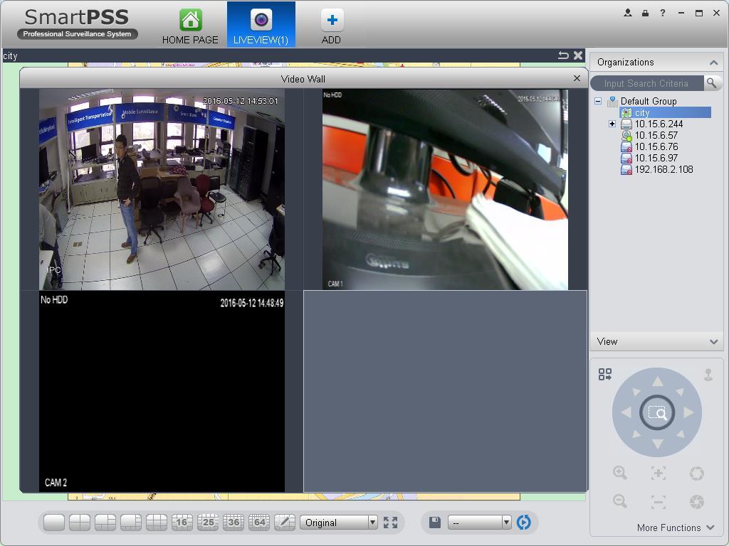
70 e) Click Save. Tips After you complete setup for one channel, you can click Dropdown in Figure 3-74 to copy current setup to other channel(s). 5) View version Video Wall Configuration This function allows you to output video to the video wall. Please follow the steps listed below. 1) Click, system goes to video wall setup interface. See Figure Figure ) Config video wall. a) Enter video wall name and description. b) Click below, select layout as 1*1, 2*2, 3*3, 4*4 or M*M. Click screen to draw video wall physical layout, see Figure

71 Figure 3-76 Note Use Ctrl+left click mouse to select several screens, right click mouse to select splicing or click, you can combine several screens to a splicing screen. Right click mouse, select unbind splicing or click, you can cancel splicing. Select a screen and right click to select rename or delete, you can rename screen name or delete a screen. Click, you can delete all screens. c) Click Next button, you can go to video wall input binding interface. 3) Binding decoder channel Select a decoder channel and then drag it to the corresponding screen of the video wall. See Figure
 Check the box to enable setup immediately and then click Finish button, you can see an interface shown as in")
72 Figure 3-77 Note: When a screen binds M30, you need to splice physical layout, otherwise you cannot bind. 4) Check the box to enable setup immediately and then click Finish button, you can see an interface shown as in Figure
73 Figure 3-78 In Figure 3-78, double click a video wall, or select a video wall and then click Modify button, you can change its setup. You can also click Delete button or to remove. Click, you can change video wall on/off setup. 68

74 4. Basic Operation 4.1 Liveview Real-time Liveview In Liveview opqge, you can group device or channel and view real-time liveview. On the homepage, click in the Basic pane, you can go to the liveview interface. See Figure Figure Please refer to the following sheet for detailed information. 69
75 SN Item Function Please refer to the following contents for detailed information. : Enable/disable local record. 1 2 Bit stream information and shortcut operation menu Video window : Snapshot. : Enable/disable audio. : Enable/disable bidirectional talk. : Instant playback. : Digital zoom : Close current window. Real-time video 3 4 Window split mode Tour button : It is to set 1-wind to 64-window mode. : Select a window and then click this button to custmoze its setup. : Adjust video scale. : Full screen. :Save current view as a viewing profile. You can use it under View, Playback, and in tour interface. Note: When add view, check add to tour task before you can view it in tour&task. :Enable tour plan. Refer to Ch 3.9. :Close tour plan. 5 PTZ 6 Device list It is for PTZ dome camera series product only. Here you can set camera direction, zoom in, zoom out, iris and etc. Click advanced button to set preset, tour, aux function and so on. When default device tree is set to: device tree (by device), device tree shows device group and channel. When default device tree is set to: region/tree (by channel), device tree shows channel. Here you can create a new group and drag a device or channel to it. Right click a channel, you can select main stream/sub stream or quickly go to the device setup interface. 70

76 Select a liveview window, double click a device channel on the right pane to open the video. Double click a group name; you can open all channels under current group. Right click device channel, you can switch between main stream/extra stream. Right click liveview window, you can see an interface shown as in Figure 4-2. Figure 4-2 Please refer to the following sheet for detailed information. Item Close video Close all video Start audio Start talk Start record Snapshot Triple Snapshot Start instant playback Playback Multi-screen Track Function Click it to close current window. Click it to close all windows. Click it to enable audio function. Click it to enable bidirectional talk function. Save audio/video of current window to a record file. Snapshot current window. Click it once to save one picture. Snapshot current window. Click it once to save three pictures by default. It is to enable instant playback in current window. Click it to go to the playback interface to playback record of current window. It can split screen to 1+3, 1+5 mode for 4K camera main stream. You can drag small box in video window. 71
77 Item Fisheye installation mode Fisheye view Window scale Stream type Adjust Intelligent Overlay Channel setup Full-screen Function It is to adjust fisheye installation mode. It includes: ceiling mount, wall mount and ground mount. It is to adjust fisheye view mode. It is to adjust window scale. Switch between main stream/sub stream Set video brightness, contrast, hue and saturation. Overlay intelligent rule, intelligent pattern and intelligent object box in video window. Click it to go to the channel setup interface. Click it to switch to full screen mode. You can double click video window or right click mouse and then select exit full screen/press Esc to exit Record During the liveview process, you can follow the steps listed below to record. On the liveview interface, right click mouse and then select record button. Or you can click the button The icon becomes at the top of the video window to record. when device is recording. You can right click mouse to select stop record or click the stop record. at the top of the video window to The default record save path is SmartPSS/Record. Here you can go to chapter 3.3 General and then select file setup icon to modify record save path Snapshot During the liveview process, you can follow the steps listed below to snapshot. 1) On the liveview window, right click mouse and then select snapshot. You can see system Tips pops up snapshot dialogue box. See Figure 4-3. You can also click at the top of the video window to snapshot. 72
 Click save button, you can see system prompts Successfully saved snapshot!. On the Liveview window, right click mouse and then click Triple snapshot, you can snap three pictures at one time.")

78 Figure 4-3 2) Please select corresponding parameter from the snapshot reason dropdown list and then input the information in the Remarks column. 3) Click save button, you can see system prompts Successfully saved snapshot!. On the Liveview window, right click mouse and then click Triple snapshot, you can snap three pictures at one time. You can see the corresponding dialogue box if the snapshot succeeds. The default picture save path is SmartPSS/capture. Here you can go to chapter 3.3 General and then select file setup icon to modify picture save path E-Map E-map is shown in device list not. You can directly drag map into preview window for preview, as well as save map into image for next time use. Via e-map, you can better visualize position of video channel or alarm channel and see live preview of the channel or alarm status Edit E-Map 1) You can go to device list on the right of Preview window, right click the default group or any group, select New Map, see Figure 4-4. Figure
 In map edit interface, drag video channel or alarm input you want to be displayed on map to designated position, see Figure 4-5.")
79 2) In map name field enter name of map, select picture and save it to enter edit page. 3) In map edit interface, drag video channel or alarm input you want to be displayed on map to designated position, see Figure 4-5. Figure 4-5 4) On map set monitoring range of video channel, see Figure 4-6. You can slide the bar at the upper right corner to set opacity, see Figure

80 Figure 4-6 Figure 4-7 5) After you finish edit, click to save map. 6) Click to return to preview. Parameter Save New Area Edit Map Opacity Note Save current map you are editing. Create new area on map. Modify map name and picture. Set opacity of monitoring range Preview E-Map You can directly drag map you want to preview from device list into idle window, or select one idle window, in device list double click map. Map can be zoomed in/out and you can move mouse to see every detailed position info, see Figure
81 Figure 4-8 After you open map, you can move your mouse to a video channel to see short preview. You can click a video channel, then the video channel will be opened next to your mouse, see Figure 4-9. Click again to close video. 76

82 Figure 4-9 You also can right click in blank area, select open all channels or video wall to preview all channels on the map, see Figure 4-10 and

83 Figure

84 Figure 4-11 When alarm occurs, corresponding channels on map will flash Fisheye Installation of fisheye includes in-ceiling, wall mount and ground. In-ceiling supports 8 views, the ground mounted 1+4 mode is illustrated by Figure 4-4. Figure 4-12 In the left, fish eye splits into 4 scene boxes, if you drag one box with mouse, as :, the corresponding above scene box will rotate. Wall mount supports 5 views, and ground supports 7 views Smart Alarm If the system configures SmartIPC device, then you can configure rule for smart channel of the device in Liveview interface. Step 1. In Liveview interface, device list on the right, right click intelligent device, select IVS Channel Cfg. See Figure


85 Figure 4-13 Step 2. In channel list dropdown list, select channel, see Figure 4-6. Figure

86 Step 3. Click. See Figure 4-6. Figure 4-15 Step 4. Configure rule name, and select rule type. Step 5. In video window, draw detection region, and right click to complete drawing. Click Redraw to draw detection region again. Click Clear to clear drawn detection region. See Figure

87 Figure 4-16 Step 6. Click Config. Step 7. Set parameters, select A<- ->B, A-->B or A<--B, see Figure Figure 4-17 Step 8. Click Time Setting, set time, see Figure

88 Figure 4-18 Step 9. Click Alarm Message. Step 10. Check alarm output, record, snapshot and click OK. Step 11. Click Apply. When alarm occurs, in LOG interface, you can select alarm log for type, and IVS device for device name to search alarm info. See Figure
 In device list on the right of Liveview window, right-click smart track device, select Smart Track Config.")
89 Figure Smart Track The system supports smart track in Liveview interface. 1) In device list on the right of Liveview window, right-click smart track device, select Smart Track Config. System pops up Smart Track Config box, see Figure


90 Figure ) Click, select PTZ dome device. Note: Do not link more than 3 PTZ cameras at the same time. 3) Click Save. See Figure Figure
91 4) Click Add. 5) In fish-eye device list on the left,, select one point. Then image shown on the right will turn to the this selected point, click. Note: To improve accuracy of track, mark of first group shall be a far fixed reference object. 6) Repeat step 4 and 5, add at least three points. See Figure Figure ) Click OK. 8) Right click device on the right in fish-eye device list, select Smart Track. System pops up smart track box, see Figure


92 Figure ) Click a random point on device on the left, PTZ camera on the right will auto turn to the related position. In this interface, you can correct smart track by clicking on dewarp at the upper-right corner, please refer to Ch PTZ If the device type is PTZ dome camera, you can click the PTZ button to set. See Figure

93 Figure 4-24 Please refer to the following sheet for detailed information. Item Function Click to go to the PTZ menu. See Figure PTZ menu Figure 4-25 Mouse simulator Click direction., you can use your mouse to set camera movement Direction buttons Zoom Focus Iris Step Preset Tour Horizontal rotate Scan Pattern Aux It is to set camera movement direction. There are total 8 directions. Top/bottom/left/right/top left/top right/bottom left/bottom right. It is to control speed dome to realize zoom function. It is to adjust video definition. It is to adjust brightness. It is to control PTZ movement speed. It supports value 1 to value 8. There are 128 presets by default. You can set camera to a specified preset. Use direction keys to move the camera to your desired location and then input preset value. Click Set button, you have set one preset. This function allows the camera to move between several presets. It is to enable horizontal rotate function. It is to set two limits so that the camera can move back and forth. The camera can memorize dome operation such as pan, tilt, and zoom to repeat. It is to set aux positioning Preset This function allows you to set camera to a specified position. Preset setup 88
 Click dropdown list, select preset; click and click dropdown list. Select number within 1~128. 3) Click to set corresponding preset.. 4.1.8.2 Tour This function allows camera to go between several presets.")
94 Please note system supports a max of 128 presets by default. 1) In Figure 4-24, use direction keys to move the camera to your desired location. 2) Click dropdown list, select preset; click and click dropdown list. Select number within 1~128. 3) Click to set corresponding preset Tour This function allows camera to go between several presets. Important Before you use this function, please set at least two presets. Tour setup 1) In Figure 4-24, select Tour from the dropdown list and then click button. See Figure ) Input tour number/tour name. Figure ) Select preset number from the dropdown list and input stay time. 4) Click button to add one preset to the tour. Select another preset number from the dropdown list and then click Add button again to add more preset to the tour. 5) Click OK button to complete the tour setup. 6) Click button to tour Pan 1) Click dropdown list, select Pan. 2) Click to enable Pan. 89
95 Scan 1) Click dropdown list, select Scan. 2) Click PTZ button, to rotate left, click, set left border. 3) Rotate PTZ to right, click m set right border. 4) Click to enable Scan. PTZ will rotates within the range of two borders Pattern Pattern is the process of recording. 1) Click dropdown list click Pattern. 2) In dropdown list select number of pattern, you can set up to 5 patterns. 3) Click, after button is red, operate on 8 buttons of PTZ to start setup of pattern. 4) Click, complete pattern setup. 5) Click, deivce will rotate accoridng to set pattern Aux 1) Click dropdown list, select Aux. 2) In Aux order box, input any number between 1~255. Each number has a corresponding function. 3) Click, display function of Aux order. 4.2 Playback After you recorded a file, you can go to this interface to playback. On the homepage, click in the Basic pane, you can go to the playback interface. See Figure

96 Figure SN Item Function 1 2 Shortcut operation column Playback window There are shortcut operations to download record file and snapshot. : Snapshot. : Zoom in window : Close current window. Playback record 3 Mode There are two playback mode: by time/by event. 91
97 SN Item Function It is to control the playback process, audio and etc: :Window sync operation button. When this function is enabled, the operation of the playback bar is for all windows. When it is in is for current selected window only. status, it 4 Playback bar tool :It is to switch playback and pause. :Stop playback. :Forward by one frame. :It is to control the playback speed. :It is to adjust volume. : Motion detect the zone. 5 Window display mode setup It is to set window split mode. The value ranges from 1- window to 36-window. : Select a window and then click this button to realize customized setup. : Full screen. 6 Time control bar It is to zoom in /zoom out time line. 7 Time bar Playback time process. 8 Time clip It is to edit the time line to download the specified records. 9 Export process It is to export the records of the specified period Playback Device Record Please follow the steps listed below to search the record you want and then playback. 1) In Figure 4-27, click Device button on the upper right intergface. 2) Check a channel (or some channels) on the device list on the top right pane. 3) Select record type, stream type and record start time and end time. 4) Click Search. See Figure By default, system search record by time. 92
 Click to intelligently search motion detection. System shows motion detection window. 7) Left click to select motion detection area with the box. 8) Click to search motion detection.")
98 Green color stands for the general record. Figure 4-28 Yellow color stands for the motion detect record. Red color stands for the alarm record. Blue color stands for card no. record. 5) Click to play record. 6) Click to intelligently search motion detection. System shows motion detection window. 7) Left click to select motion detection area with the box. 8) Click to search motion detection. The purple time bar represents found motion detection in Figure Figure ) Click to play motion detection in video window. 93
 Click, to playback record. See Figure 4-24. Figure 4-30 12) Select Picture on the right. 13) Configure search time, click Search.")
99 : Re-select motion detection area. : Exit intelligent search. 10) Click event below video window. System search record file by event. 11) Click, to playback record. See Figure Figure ) Select Picture on the right. 13) Configure search time, click Search. System shows snapshot, see Figure
 (optional) You also can playback record under View.")
 Input video name, click OK.")
100 Figure 4-31 You can click to view snapshot. 14) (optional) You also can playback record under View. a) In Liveview interface, click at bottom. System pops up Figure Figure 4-32 b) Input video name, click OK. c) On the right, click View tab, right click newly added view, select Playback. d) System auto jumps to playback window, and shows process bar at the bottom. 95
 In Figure 4-27, click Local button on the right pane. 2) Check a channel (or some channels) on the device list on the top right pane.")
101 e) Click to play record, see Figure Figure Playback Local Record Please follow the steps listed below to search the record you want and then playback. 1) In Figure 4-27, click Local button on the right pane. 2) Check a channel (or some channels) on the device list on the top right pane. 3) Set search for record or picture, and select local record or picture time to search. 4) Click to search record or snapshot of the device at Liveview (see Ch or 4.1.3). 5) Now you click to playback window. And click to rewind. Click to view picture Export There are three ways for you to select export records. 10) In Device record interface, select periods on the time line and then click to export records. 96

102 11) In Record event interface, select record type and then click to export records. 12) In Local record interface, check the records first and then click to expoer records. You can see the export interface is shown as in Figure Select the corresponding export path and then click OK button to export. Figure 4-34 You can click to view exporting and exported conditions Fisheye Playback You can use fish eye to playback device record and local record. For example to play local record. In playback window, click local record tab. After you search out record, you can select fisheye view to playback the record. See Figure

103 Figure Alarm Manager If you have set an alarm scheme, you can see the corresponding alarm in the Alarm manager interface. You can refer to chapter to set an alarm scheme first. Click icon in the basic pane, you can go to Alarm manager interface. See Figure
, you can see system instantly shows video window. See Figure 4-37.")
104 Figure 4-36 You can click next to operation column in alarm interface to view linked record, and click to view linked snapshot. If you have set alarm activation video function in your alarm scheme setup (chapter 3.7), you can see system instantly shows video window. See Figure If you check the box at the bottom of the interface to pause refresh, the new alarm info will not be shown in alarm list instantly. Click Alarm Manager at the right bottom of the interface, system goes to the alarm manager interface for you to view the corresponding alarm record. Figure
105 4.4 Video Talk It supports call, live preview, remote unlock, message sending, right config and info search. For fence station, you shall select device type as fence station on WEB. Go to System Settings>Local Config>Device Type, select device type as fence station. In System Settings>LAN Config set building no., unit no. both to 0, set MGT center IP to the installation IP address of SmartPSS.VTO select its building no. and unit no. according to actual condition on WEB. On VTO web, you can create room no., and VTH config self room no. and VTO on device local GUI while room no. must exsit on corresponding VTO. For example, Unit 1, Building 1. VTO WEB can create room no., VTH config its room no. and corresponding VTO on device local GUI. Note: After fence station and VTO web interface are configured, you need to add to SmartPSS Client, please refer to Ch 3.5 for steps to add device. After device is added, in SmartPSS Client video talk interface, in the device tree on the right, building no., unit no. reported by each device will create device tree. Fence station shoes its own name VTS Center In homepage Basic function area, click. System pops up video talk VTSinterface, see Figure Figure 4-38 VTS address is the address required by talk with device tree, system will auto get local address. If local IP address is not set, the gotten address will be User fill in and confirm, as well as click to set again. 100

106 A user can select online or offline and in offline status, all incoming calls will auto be transferred to other idle VTS. Currently only support VTH transfer, cannot transfer VTO. If VTO is connected to VTS directly, then VTS has the priority to answer call. A user can click sequence button or click and drag VTH to sort, then incoming call be answer according to this sorted sequence. A user can answer call or transfer call, see Figure Figure Monitor Click Monitor tab. In Monitor interface, you can unlock, one-way call fence station or VTO and other operations, see Figure

107 Figure 4-40 Click in the window, or at lower bottom, or right click to select start call. All of these allow client to one-way call VTO or fence station, so the VTO or fence station can hear call from client. Click in the window, or at lower buttom, or right click to select unlock. Click, in the window, or right click to select snapshot, start record. You can snapshot or record the live preview. In video window, right click menu includes snapshot, record, switch string type, adjust window scale and etc. Please refer to Ch Talk Click talk tab. Below contact there is info of fence station or VTO in format of unit, and on the right there is VTH under this unit. See Figure


108 Figure 4-41 Click VTO. It shows detailed VTH under fence station and VTO, registration to client and VTH online number and total, if shows status of device failed, then you can talk to VTO/fence station/vth; user can click to switch VTH display mode, see Figure Figure 4-42 If client needs to call VTO in a certain unit. 103
109 1) Right click VTO and select shout. System pops up a box, see Figure Figure ) Click. 3) System pops up dialogue box, click OK. You can remotely unlock VTO. 4) Click, to stop existing call. Call window will not close. If client needs to call a VTH in a specific room and unit. 1) Click on VTH name card. Please note client and VTH can talk to each other as a bidirectional talk. System pops up a box, see Figure

110 Figure ) When VTH picks up, client can talk with VTH. See Figure Figure 4-45 If VTH does not answer over 60s, then client pops up a box to ask if you want to dial again. You can click to re-dial. If the VTH is busy or hang up call, client will ask you to try again later. If VTO is calling client. Client pops up VTO call box, see Figure


111 Figure 4-46 You can click to answer VTO call, and start a bidirectional talk. You can click to unlock. If VTH is calling client. Client pops up VTH call box, see Figure Figure 4-47 You can click to talk with VTH. If there is missed call, in talk interface, in the lower-right, missed calls are shown here. See Figure


112 Figure 4-48 You can view all call histories. Click to call missed call. When you search in, it requires accurate building no., unit no., and fuzzy room no. For example, input 1#1# as to search all devices under unit 1, building 1. If input 1#1#10 as to search all VTHs under room no. 10. You also can set name and telephone phone number on each device name card and when search, directly input building no.#unit no.#name keyword to search. On the right, you can directly dial to callvto as a one-way talk, to call VTH as a bidirectional talk. Example: dial 1#1#6901, as to call Building 1 Unit 1l enter 1#1#101 as to call Building 1 Unit 1 Room 101 VTH Announcement Click announcement tab. Input title, contents, see Figure


113 Figure 4-49 In the device list on the right, check one or more VTHs, click send. During sending, the send button is grey, and if you want to continue to send announcement, you shall wait until the send button resumes. You can view announcement information on VTH Info Search Click Info Search tab, sub tab includes alarm record, unlock record and call record. Alarm record user can search VTO and VTH alarm event, support pop-up display of VTO alarm event, see Figure Figure 4-50 Unlock record allows user to search VTO unlock record, see Figure


114 Figure 4-51 In call record, user can search VTO call record, see Figure Issue Card Click Issue Card tab, see Figure Figure

115 Figure 4-53 In search, room no., room no. shall be accurate but name support fuzzy search. When a user selects node where the user issuing card is, then click Issue Card, see Figure Operation steps: Figure User can select device to authorize, click the dropdown list of device, check device (fence station is checked be default); user also can give priority to group config and authorize right to device under this group, and click Link Device on the right of organization node, to select default device. 2. Fill in username. 110
116 3. Select card type: user card, administrator card. 4. Fill in room no. 5. Select record method:support manual input and card issuer. Manual issuing requires user to fill in card, and click Issue Card button. If via card issuer, user click Start Read, when card is successfully read, the system will auto link user to card issuer list; if card eixsts in device, it will fail. 4.5 Access SmartPSS integrates access control device with effective management and configure of device. It achieves modularization of access business and integrates access with video link and e -map. Note: Access controller must be added into SmartPSS client, please refer to device adding steps in Ch 3.5. Access device default port no.: 37777, username: admin, password: Added access controller are all configured in SmartPSS device, please see: General-Network (refer to Ch ), support device IP setup. System Maintenance-User (refer to Ch ), support device password setup. System Maintenance-System Maintenance (refer to Ch ), support device time setup and upgrade. After device is added, in SmartPSS client Access interface, in device tree on the left, device tree is auto created. In BASIC area in homepage, click to enter Acess interface Console In Access interface, you can click monitor and control all access control devices. See Figure on the left to enter Console interface which can 111

117 Figure 4-55 No. Parameter Note Organizations:according to device(channel), set group and e-map. 1 Organizations/ Zones Zones:axcording to channel, set group, e-map. By default, it shows organizations, you can go to Homepage- Settings-General-Basic, to set organizations. Search support keyword of each node. 2 List/View 3 Event List:Access status displsy and control. View: Video/e-map preview and control. Access event:view alarm event, abnormal event and normal operation. View event:device info and user info Organizations/Zones You can right click New Group at node, to drag device or channel into different groups for management, and right click on node, see Figure

118 Figure 4-56 Parameter New Group Open/Close All Note Create sub group, rename group and delete group. Note: Only when group node is null, you can delete it. You cannot delete default group. Open\Close accesses under all groups. Create e-map, click New Map, enter map name and select picture to enter map edit, see Figure New Map Access/video channel dragging Video monitoring range setup Monitoring range opacity setup Add hot zone, max 3 hot zones Edit map Save map 113


119 Figure 4-57 You can right click at access device node and operate device, see Figure Figure 4-58 Parameter Real-time Monitoring Details Extract Card Info Note Real-time extract device event info. Device details search, including: device name, device IP, device type, device model, device status, SN, and version. Extract device stored card info and fingerprint info, support to export and import into user management (to department node be default). 114
, anti-pass back, inter-lock, first card unlock and multi-card unlock. Display all channels.")

120 Parameter Sync Data All Doors Reboot Device Note Delete all device info(excluding card record and alarm record),sync user data with device, the data include right, (user-related, period), anti-pass back, inter-lock, first card unlock and multi-card unlock. Display all channels. A&C device reboot remotely. You can right click at access channel node, and operate device, see Figure Parameter Note Figure 4-59 Open/Close Change Channel Name Client remotely open/close door. Edit channel name and channel display/hide. Door Configuration Door parameter setup, please see Figure Figure
121 Reader (card reader): support naming of reader, and setup of entry/exit status. The following is default setup. Single door one-way: 1 in 2 out. Dual door two-way: 1/3 in, 2/4 out. Four door one-way: 1/2/3/4 in Access status: normal, NO, NC Door lock hold time: 1s~600s. Door not locked timeout: 1s~9999s. NO period: within access period, door is normally open; close by default. NC period: within access period, door is normally clock; close by default. Holiday period: within access period, in holiday period, holiday period has priority; null by default. Unlock method: support card, password, fingerprint, card+password, card+fingerprint, card or password or fingerprint, by period. Note: When a door is set to multi-card unlock, unlock method is invalid, see Ch By period: support Monday-Sunday, four periods per day, each period supports a different unlock method. Alarm enable: Duress: forced to swipe card, alarm occurs Intrustion: instrusion, alarm occurs Timeout: door not locked, alarm occurs Sensor enable: door open status is judged according to door sensor You can right click within tree range to achieve one-level directory grouping and tree sequence, see Figure Figure 4-61 Parameter New Group Sort by Type Sort by name (default) Note Level 1 directory grouping. Sequence according to device/channel type. Sequence according to name. You can right click in e-map node, and edit, delete and rename e-map. Global control can achieve one-click NO/NC of all access channels under emergency List/View In list mode you can achieve access live preview and monitoring, see Figure


 camera icon on mao to open video, right click access control on")
122 Figure 4-62 You can preview video and e-map in view mode, see Figure Video preview: please refer to Ch Figure 4-63 E-map preview: After you edit map, you can drag e-map into video window for preview. Scroll your mouse to zoom in/out; click (or move mouse to range within camera) camera icon on mao to open video, right click access control on mao to enable/disable access. Right click in e-map preview window, see Figure

123 Figure 4-64 Parameter Close Video Close All Video Open All Channels Video Wall Open All Doors Full Screen Note Close current e-map window. Close all video windows. Open all channels on e-map Output all video channels in e-map to video wall Open all accesses on e-map Display current window in full screen You can click to siwtch video format. The first three formats are standard formats in your favorites, click to split interface, see Figure Figure 4-65 You can click add to favorite icon (red heart) to add format into favorties. Standard split: 1, 4,6, 8, 9, 16, 25, 36, 64. Custome split: there are 9 types of custom split, see Figure

 4.5.")
124 Figure Event You can view all live preview access events and their details of monitored device, see Figure Figure 4-67 Parameter Lock Clear User Info Device Info Note Lock event in current event info, during the period the locked event will not be shown in list but user can search for it in log. Clear event in current event info, not delete it from log. User info: photo, name, department, tel Device info:device IP, device type, device model, device status(online, offline) User Management In Access interface, you can click manage all users. See Figure on the left to enter User Management interface, to 119

125 Figure 4-68 No. Parameter Note 1 Department Tree Department management, support to add/delete/edit department organization and people count. 2 User Info User management, show corresponding user info under department node. Sort card issuing, lost, frozen, edit and etc. of user. Sort user Department Management At department node or blank area in department tree, you can right click to operate, see Figure Figure

126 Parameter Add Department Edit Department Delete Department Search Department Note Add department sub node or level 1 department node. Name of departments at same level cannot be repeated. Edit department name. Delete existing department. You cannot delete department which contains user. Support search of department node keyword User Management In User Management interface, you can click see Figure button, select type of card you use, Figure 4-70 It supports ID/IC cards Warning: If card type and card reader do not match, then you cannot read card no.! In User Management, youc an click button to manually add user info. User info mainly includes basic info, fingerprint, details, see Figure 4-71 to

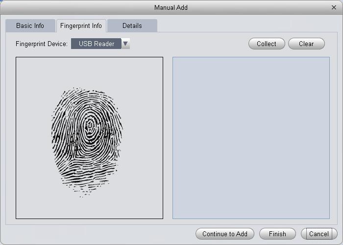
127 Figure 4-71 Figure

128 Figure 4-73 Parameter Note User ID mandatory Name mandatory Department Card no.:input by card reader and manually Basic Info Card type:general card, VIP card, guest card, blacklist card, patrol card, and duress card Unlock password:only used for unlock via password Card password:used for card+password unlock Number of use:only for guest card Validity:card validity, 10 years by default Picture:user photo, max 120K Collect fingerprint via fingerprint device and reader Fingerprint Info V1 fingerprint: Each user can have up to 3 fingerprints V2 fingerprint: Each user can have up to 2 fingerprints Support input of fingerprint name Details Gender, title, education and etc. Warning: User ID and card no. cannot be repeated! 123

129 In User Management interface, you can click Figure button to batch issue card, see Figure 4-74 Parameter Note Step: Manually check user to want to issue card to auto filter out users already have card Batch Issue Card by User Click Batch User select card issuing device: support card issuer and card reader of controller. Click read card no, and device starts to read. Place card on device, link user to card no. one by one. Click save to complete card issuing. 124

130 Parameter Note User click to batch issue card Enable Batch Issue Card by Work ID Enter starting User ID auto filter out users already have card Click to get user and complete adding user to have card. Click read card no., so device starts to read card no. Place card on device one by one to link card to work ID by sequence. Click save to complete. In User Management, you can click button to edit user, see Figure Figure 4-75 Parameter Note Check user you want to edit. Department Click Edit. Select new department. Click OK. Complete. Check user you want to edit. Validity Click Edit. Check valid time. Set time. Modified valid time will be sent to device. Complete. 125
131 In User Management interface, click button to delete user. Check user you want to delete, click Delete. Confirm that all information and rights of the user you are doing to delete will be deleted from the device. You can click either of to import/export user info. Import/export info includes: work ID, name, card no., card type, department, fingerprint name, fingerprrint name. Note: During data importing, it auto generates department. Warning: If imported data (User ID/card no.) already exists, it will not import the information. In User Management interface, you can click. Parameter Note Modify user info. Delete user info. Clear user card no. and delete card info in device. Freeze card no. in device. You can click unfreeze if you want to restore frozen card. In User Management interface, you can click user. Note: Work ID and name suopport fuzzy search. Card no. supports accurate search. to search keyword of Permission Management In Access interface, you can click on the left to enter Permission Management which allows management of right about user issuing card Door Group Right In User Management interface, you can click door group right, and set a specific period of time, a specific door or door group can be unlocked via verification, see Figure

132 Figure 4-76 No. Parameter Note 1 Door Group Info Client door group info list 2 Door Details Group Details of current door group 3 User Info User right info of current door group In Door Group Right interface, click, see Figure

133 Figure ) Enter name of door group, which cannot repeat existing door group name. 2) Select access period. 3) Check door, click Save. Click button to re-edit door group info. Wanring: Door group name cannot be repeated! In Door Group Right interface, lcick to add use right, see Figure
 In search list dropdown list, select department of user you want to add or")
134 Figure 4-78 No. Parameter Note 1 User List Existing user info with door group right 2 Search List Info of user without door group right 1) In search list dropdown list, select department of user you want to add or directly enter User ID or name. 2) In search list check searched user and add to list. 3) You can delete user who already has right. 4) Click Save, to complete the selected user into all door groups. Note: In search list filter out user who do not have card no. info. In Door Group Right interface, you can click button to delete all information and right of the door group in the system. Warning: During right issuing process, please sure client and device are will connected User Right 129
 Click OK as to confrim cancellation or adding of personal user right. 4.5.3.")
135 In User Management interface, you can click in User Right interface to add specific user into access right list, or delete specific user from list. 1) Check or cancel checked door group. 2) Click OK as to confrim cancellation or adding of personal user right First Card Unlock In Permission Management interface, click First Card Unlock, you button to set within specific period, only when user with first card unlock right pass verifiction for the first time, door status will be normal or NO and will be close after this period ends, see Figure ) Select to enable first card right door. 2) Select period. Figure ) In search list, selete user with first card right. 4) Check user. 5) Click Save. Wanring: 130
136 For user who is auto filtered out in search list due to lack of right of the door, he/she must be given right of this door by first card right holder Multi-door Lock You can click Multi-door Lock to set that a specific door can be unlocked only when specific users of a group all pass verification in a specific order. Before verification is passed, the users must verify in the designated order. You can click User Group Management button to set group info. See Figure Figure ) In User Group Management interface, click, see Figure
 In Multi-door unlock setup interface, check group. 7) Fill in valid number of user for each group. 8) Select unlock methof for each gourp. (card, password and fingerprint).")
137 Figure ) Select group member. 3) Save to complete adding. 4) In Multi-door Unlock interface, click. 5) Select door you want to enable multi-door unlock. 6) In Multi-door unlock setup interface, check group. 7) Fill in valid number of user for each group. 8) Select unlock methof for each gourp. (card, password and fingerprint). 9) Click to adjust sequence of unlock. 10) Click Save. Note: A group can contains up to 64 users. A door with enabled multi-card unlock supports up to 4 groups to verify at the same time, total number of user cannot exceed 64; total valid user cannot exceed Anti-pass Back In Permission Management interface, click Anti-pass Back to set verification user. A user verifies at door A must verify at door A again when exits since card record must match one to one. If a user does not verify when enters, he/she will not pass verification when exits. 132

138 You can click in Anti-pass Back interface. See Figure Figure ) Select access controller to use anti-pass back. 2) Select anti-pass back rule according to access controller. 3) Confirm. Note: Rule of anti-pass back: Unit/single door controller: door reader anti-pass back. Dual door controller reader 1 and 2 anti-pass back, reader 3 and 4 anti-pass back, reader 1/3 and 2/4 anti-pass back, reader 1 and 2/3/4 anti-pass back. Four door controller: reader 1 and 2 anti-pass back, reader 3 and 4 anti-pass back, reader 1/3 and 2/4 anti-pass back, reader 1 and 2/3 anti-pass back, reader 1 and 2/3/4 anti-pass back Inter-door Lock In Permission Management interface, click Inter-door Lock, to set inter-lock between two doors on one access controller. When one door is unlocked, other doors will be locked. If you want to unlock one door (under normal status), all of the others shall be locked, otherwise you cannot unlock this door. You can click in Inter-door Lock interface. See Figure


139 Figure ) Select access controller to inter-lock. 2) Select rule of inter-lock. 3) Confirm. Note: Role of inter-lock: Single door controller has no inter-lock. Dual door controller: 1-2 door inter-lock. Four door controller: 1-2 door inter-lock, 3-4 door inter-lock, door inter-lock, door inter-lock Remote Verification In Permission Management interface, you can click Remote Verification to ask the client to let user who passes verification enter within certain period, and admin will judge whether to unlock or not. You can click in Remote Verification interface. See Figure Figure ) Select door and time to enable remote verification. 2) Save Period Setup In Permission Management interface, click Period Setup to set specific reader to be valid with specific period and not valid on other periods, as well as set that user can only access a specific 134


140 door within a specific period. Period is used for NO period, holiday period, first card period, remote verification period, door group right period; you can click interface, see Figure in Period Setup 1) Enter period name. 2) Select daily period for Monday to Sunday. Note: Figure 4-85 A device supports to 128 periods setup with daily limit of 4 periods Holiday Setup In Permission Setup interface, click Holiday Setup to set different access period from general period. You can click in Holiday Setup interface. See Figure Figure
, link event includes: alarm, abnormal, normal event, link event")
141 Note: Within holiday period, holiday has priority in execution. Holiday period is for access only Event Configuration In Access interface, you can click Event Configuration. You can set that when a input point inside access system triggers a specific event, client will have video link(live preview/record), link event includes: alarm, abnormal, normal event, link event pop-up plus display in log. Please refer to the following for configuration of event scheme. 1) Click Add. 2) Set name and event type, select channel and check Enable. Event type includes alarm event, abnormal event, normal event and external alarm. See Figure ) Click Next, set link video channel. Figure ) Under Link Setup tab, drag channel and set link channel, window no., stay time and etc. of link channel. See Figure Note:External alarm supports access controller link. 136
 Click Next and configure scheme time.")
142 Figure 4-88 Note: Stay time range is 5s to 180s. 5) Click Next and configure scheme time. See Figure

143 Figure ) Behind each week, there is, click it to set accurate time each day. 7) Click Confirm. See Figure Figure 4-90 You can modify, delete, disable, enable scheme, as well as batch impoty/export scheme. Event Type Description Chassis alarm:alarm triggered when card reader of the controller is forced to be removed. Intrusion alarm:excluding normal door open conditions, other door open conditions detected by door sensor 1 Alarm Event Duress alarm:alarm triggered when door is opened by duress card (fingerprint). Door left open alarm:door remained open exceeding set time Blacklist alarm:alarm triggered when door is opened via card on balcklist. 138
144 Event Type Description Unauthorized or card lost: alarm triggered when the card has no right to unlock this door or it has been reported lost. Card suspended:after the card is suspended, it cannot be used. Event is triggered at verification. Unlock mode error:event triggered when verification method and unlock method do not match. Card validity error:alarm is triggered when current time is not within card validity. Abnormal Event Period error:alarm is triggered when verification of current period is not in access period. Holiday unlock period error:alarm is triggered when verification of current period is not in holiday period. Incorrect first card:enable first card right, alarm is trigged when user unlock not using first card. Inter-lock mode:door with set inter-lock rule is unlocked, alarm it triggered when the other door is unlocked. Anti-pass back mode: When one enters via verification but exits without verification, alarm is triggered at his/her next verification for entry. Lock event:triggered when auto lock or door sensor detects door is locked Card unlock:triggered after passing card verification, door is unlocked Fingerprint unlock:triggered when door is unlocked after passing fingerprint verification. Normal Event Card + fingerprint unlock:triggered when door is unlocked after passing card and fingerprint verification. Card +password unlock:triggered when door is unlocked after passing card and password verification. Password unlock:triggered when door is opened via password. Button unlock:triggered when door is opened via button. 139

145 Event Type Description Multi-card unlock:triggered when the first card in multicard unlock mode passes verification. Remote verification:triggered when a user passes device verification and is asking for client verification for door under remote verification Log In Access interface, you can click Log. You can search for log according to criteria. 1) Select start time and end time. 2) Select user department. 3) Enter name or user ID. 4) Select verification method. 5) Select user entry/exit status. 6) Select device and door you want to search. 7) Select detailed event you want to search. 8) Click Search, see Figure Figure 4-91 You can reboot search criteria, export search result and view record., reset criteria., export searched log. 140

146 , extract log info of all devices or selected devices., view record Attendance In Attendance interface, click statistics., you can set attendance info to achieve user shift and Attendance You can customize attendance rule, multiple period, holiday setup, attendance device to meet different scenes. 1. Attendance Device Attendance device is used to set user sign in range, validly and effectively count important data. You can check channel on the left in organization tree as attendance device. The system auto set the selected channel into attendance device, see Figure Note: Up to 10 attendance devices. Figure Attendance Period Attendance period is used for user to account different sign in/out, late, early leave, absence, and etc. You can click Add button to enter period name. See Figure


147 Figure 4-93 Note: Start time must be within the range between start sign in and end sign out time. End time must be within the range between start sign out and end sign out time. Cross Day See Figure When end sign out time is earlier than start sign in time, the system is in crossday mode be default. Figure 4-94 Dual Period 142


148 See Figure 4-95 and Figure Figure 4-95 Figure Attendance Shift Attendance shift is used to link period within cycle peiord, it supports cycle by week, month and day. See Figure


149 4. Attendance Holiday Figure 4-97 Holiday setup is used for unified employee woek off within the range of holiday, see Figure Figure User Shift You can set user shift in Shift Select, as well as batch set temporary arrangement: Step 1. Check shift user on the left. Step 2. Click button on the right. Figure

150 Step 3. User click button to add user shift info. Set hift user times and start/end date, click OK. See Figure Figure Step 4. You can link new user shift of this department. When a user has set linked shift, all new users under this shift will be auto arranges in shift from the date of setup, vallid time period is 10 years. Note: If this department does not have linked shift of new user, its father node become valid. Temporary Shift You can select user you want to add for temporary shift. Double click date of temporary shift in calendar, or batch check users and then select date of temporary shift, click , see Figure 145


151 Figure Re0select or cancal period cancelled for temporary setup, see Figure Figure You can select user, right click date with existing temporary shift, select to cancel temporary shift; or batch check users who you want to cancel their temporary shift and then select date with existing temporary shift, click Note: If no period selected, it is days off. 146


152 Report Search You can directly view attendance data in report search, see Figure and Figure Figure Figure Note: When the client if close so cannot get attendance data, a user can Extrat. The system will ectract data of all attendance devices. Please be patient, this process can be long. 147
 Click icon on the homepage, you can go to the following interface. See Figure 5-1.")
153 5. Extension 5.1 Video Wall After you set video wall setup (chapter 3.10 ), you can output video to the video wall. You can follow the steps listed below to set. 1) Click icon on the homepage, you can go to the following interface. See Figure 5-1. Figure 5-1 SN Item Function 1 Video window 2 Video channel Connect to NVD:Video window is fixed, cannot be dragged. Connect to M30 :Video window can be moved, max is
154 SN Item Function 3 Connect to NVD: Select one video window, click 4 Video open window Clear screen, open/close window to open 1*1, 2*2, 3*3, 4*4 layouts of windows. Connect to M30:Click to open 1*1, 2*2, 3*3, 4*4 or M*N layouts of windows. :Clear all video channels or layouts on screen. :Screen on/off setup,to open/close TV wall displsy. :Clear screen and open window. 2) Select corresponding video wall from the screen information dropdown list. You can check to select real-time mode if necessary. Once you enable real-time mode, system automatically output the video to the video wall after you complete the setup. Otherwise, it does not output the video to the video wall. 3) Drag the channel on the right pane to the corresponding screen and then binding. You can view details of binding video in Internet Explorer. 1. In IE, enterm30 or NVD device s IP address. 2. Download web service pack. 3. After download is complete, system pops up login interface. 4. Enter username and password, click Login to view details of bound video source. Default username and password is admin/admin. 4) Click save as task button, you can see system pops up a dialogue box for you to input task name. 5) Please input task name and click Save button. 6) Click Output video. Please note: You can select video wall task from the task name dropdown list and then click the Output video button to view the video. Click task manager, you can view current task status. Or you can select one task and click or to modify or delete current task. 5.2 Data Report The system supports to view flow chart statistics, and generate report for data comparison. 1) Click in Advanced area. 149

155 2) Check channel on the left, set search time, click Search. See results in Figure 5-9. Figure 5-2 Chart Type:line chart and histogram. Time:today, this month, this year, optional. Filter:filter inflow and outflow. Contrast:Contrast by time or by channel, max 5 records of contrast data. Export:can export flow statistical data in format of excel file. 5.3 Log Log interface is shown as in Figure ) In homepage, click in BASIC area. 2) Select Client log and select start time/end time, and select type from the dropdown list. Click Search button, you can see the log information. 150
Smart Professional Surveillance System User s Manual Version
 Smart Professional Surveillance System User s Manual Version 1.12.1 Instrukcja pobrana ze sklepu www.ekocentrum24.pl Table of Contents 1. OVERVIEW AND ENVIRONMENT... 1 1.1 Overview... 1 1.2 Performance...
Amcrest Surveillance Pro User s Manual
 Amcrest Surveillance Pro User s Manual Version 1.0 Table of Contents 1 OVERVIEW AND ENVIRONMENT... 1 1.1 Overview... 1 1.2 Performance... 1 1.3 Environments... 1 2 INSTALLATION AND UPGRADE... 2 2.1 Installation...
E-Series Management Software User s Manual
 E-Series Management Software User s Manual Version 1.12.1 Table of Contents 1 OVERVIEW AND ENVIRONMENT... 1 1.1 Overview... 1 1.2 Performance... 1 1.3 Environments... 1 2 INSTALLATION AND UPGRADE... 2
Installation and Operations Manual
 DLA-DNA Client Software Installation and Operations Manual Model Number: DLA and DNA Series Description: DVR and NVR Client Management Software Smart Professional Surveillance System User s Manual Version
A0. Holis HD Remote Client User Manual
 8200-1368-03 A0 Holis HD Remote Client User Manual Notice Please read this manual thoroughly and save it for future use before attempting to connect or operate this unit. The information in this manual
STORM Video Management Software User s Manual
 STORM Video Management Software User s Manual Version 2.0.1 Table of Contents 1. OVERVIEW AND ENVIRONMENT... 1 1.1 Overview... 1 1.2 STORM Interface... 1 2. LOGIN... 5 2.1 Initialize Device... 5 2.2 Login
Smart Professional Surveillance System User s Manual
 Smart Professional Surveillance System User s Manual Version 2.00.0 Table of Contents 1. OVERVIEW AND ENVIRONMENT...1 1.1 Overview... 1 1.2 SmartPSS Interface... 1 2. LOGIN...3 3. DEVICES...5 3.1 Auto
Honeywell Video. Honeywell HDCS. Video Surveillance System User Manual
 Honeywell Video Honeywell HDCS Video Surveillance System User Manual Preface Symbols The following symbol may appear in this document: Symbol Tips Definition There are some tips that can help solve certain
NVMS1000. User Manual
 NVMS1000 User Manual Contents 1 Software Introduction... 1 1.1 Summary... 1 1.2 Operation Environment... 1 1.3 Install and Uninstall... 2 1.3.1 Install the Software... 2 1.3.2 Uninstall the Software...
VMS-A1 Client Software. User Manual
 VMS-A1 Client Software User Manual Contents Contents... 2 Chapter1. Overview... 4 1.1 Description... 4 1.2 Features & Functions... 4 Chapter2. Update Info... 6 Chapter3. Starting VMS-A1... 7 3.1 Installing
USER MANUAL. Mac Version
 USER MANUAL Mac Version Contents 1 Software Introduction... 1 1.1 Summary... 1 1.2 Install and Uninstall... 1 1.2.1 Install the Software... 1 2 Login Software... 3 2.1 Login... 3 2.2 Control Panel Instruction...
NVMS User Manual
 NVMS-1000 User Manual Contents 1 Software Introduction...1 1.1 Summary... 1 1.2 Operation Environment... 1 1.3 Install and Uninstall... 2 1.3.1 Install the Software... 2 1.3.2 Uninstall the Software...
Outdoor IPC Web Operation Manual Version1.0
 Outdoor IPC Web Operation Manual Version1.0 1 Table of Contents 1 Network Connection...4 2 Main Interface Introduction...5 2.1 Log in...5 2.2 Monitor Channel Menu Tree...8 2.3 System Menu...10 2.4 Monitor
NVMS User Manual
 NVMS-1000 User Manual Contents 1 Software Introduction...1 1.1 Summary... 1 1.2 Operation Environment... 1 1.3 Install and Uninstall... 2 1.3.1 Install the Software... 2 1.3.2 Uninstall the Software...
Smart Professional Surveillance System User s Manual
 Smart Professional Surveillance System User s Manual Version 2.0.2 Table of Contents CYBERSECURITY RECOMMENDATIONS... VII Cybersecurity Recommendations... vii 1. SMARTPSS OVERVIEW... 1 1.1 SmartPSS Overview...
K6 Series IP Camera Web Operation Manual
 K6 Series IP Camera Web Operation Manual Version1.3 1 Table of Contents 1 Network Connection...4 2 Main Interface Introduction...5 2.1 Log in...5 2.2 Monitor Channel Menu Tree...7 2.3 System Menu...10
NVMS User Manual. Version 2.1.0
 NVMS-1000 User Manual Version 2.1.0 Contents 1 Software Introduction... 1 1.1 Summary... 1 1.2 Operation Environment... 1 1.3 Install and Uninstall... 2 1.3.1 Install the Software... 2 1.3.2 Uninstall
NVMS1000. User Manual
 NVMS1000 User Manual Contents 1 Software Introduction... 1 1.1 Summary... 1 1.2 Operation Environment... 1 1.3 Install and Uninstall... 2 1.3.1 Install the Software... 2 1.3.2 Uninstall the Software...
Speed Dome Web Operation Manual. Version 3.0.0
 Speed Dome Web Operation Manual Version 3.0.0 Table of Contents 1 Network Connection...1 2 Main Interface Introduction...2 2.1 Log in...2 2.2 Live Interface...4 2.3 Encode Setup...4 2.4 System Menu...5
Manual Version: V1.15. Video Management Software Guard Station User Manual
 Manual Version: V1.15 Video Management Software Guard Station User Manual Thank you for purchasing our product. If there are any questions, or requests, please do not hesitate to contact the dealer. Disclaimer
W Box VMS BOX T E C H N O L O G I E S.
 W Box VMS BOX T E C H N O L O G I E S www.wboxtech.eu Contents Contents... 1 Overview... 3 1.1 Description... 3 1.2 Running Environment... 3 1.3 Function Modules... 3 Live view... 6 2.1 User Registration
Manual Version: V1.01. ISS Manager Video Management Software User Manual
 Manual Version: V1.01 ISS Manager Video Management Software User Manual Notice The information in this manual is subject to change without notice. Every effort has been made in the preparation of this
Speed Dome Web3.0 Operation Manual. Version 4.2.0
 Speed Dome Web3.0 Operation Manual Version 4.2.0 Table of Contents 1 Network Connection...1 1.1 Preparation...1 1.2 Log in...1 1.3 Live Interface...3 1.4 Encode Setup...3 1.5 Video Window Setup...4 1.6
Speed Dome Web3.0 Operation Manual. Version 4.3.0
 Speed Dome Web3.0 Operation Manual Version 4.3.0 Table of Contents 1 Network Connection...1 1.1 Preparation...1 1.2 Log in...1 1.3 Live Interface...3 1.4 Encode Setup...3 1.5 Video Window Setup...4 1.6
Smart Phone Monitoring Software User s Manual
 Smart Phone Monitoring Software User s Manual Version 3.43 Table of Contents 1 OVERVIEW... 1 1.1 General Introduction... 1 1.2 Features... 1 1.3 Compatible Models... 1 2 DOWNLOADING AND INSTALLATION...
Montavue MNR800 Series NVR User Manual
 Montavue MNR800 Series NVR User Manual Table of Contents 1 Local Basic Operation...1 1.1 Boot up and Shutdown...1 1.1.1 Boot up...1 1.1.2 Shutdown...1 1.2 Change/Reset Password...1 1.2.1 Change Password...1
errors, or places that do not match the product. If you have any unsolved please contact our technical support department.
 - 0 - Statement: This manual may contain several technical inaccuracies or typographical errors, or places that do not match the product. If you have any unsolved problems in the process of using product
Enterprise Pro Surveillance System User s Manual
 Enterprise Pro Surveillance System User s Manual 1 Table of Contents 1 FEATURES... 6 2 INSTALLATION... 8 2.1 Environment...8 2.2 Installation...8 2.3 Un-installation...10 3 NAVIGATION AND CONTROLS OF THE
Smart Player Operation User s Manual
 Smart Player Operation User s Manual Version 3.39 Table of Contents 1 General Introduction...1 1.1 Overview...1 1.2 Features...1 2 Installation...2 2.1 Installation Steps...2 2.2 Open and Uninstall Player...4
HD IPCameras User's Mannual
 Thank you for purchasing our products, if you have any questions or need, please feel free to contact us. This manual applies to IPC-XXX series of network cameras. This manual may contain technical inaccuracies
NVMS-7000 Client Software User Manual Version 1.03
 NVMS-7000 Client Software User Manual Version 1.03 Contents Chapter 1. Overview... 3 1.1 Description... 3 1.2 Running Environment... 3 Chapter 2. Starting NVMS-7000... 4 2.1 User Registration... 4 2.2
User s Manual of DVR ULTIMAX. Remote Client Software V wersja 2.40
 User s Manual of DVR ULTIMAX Remote Client Software V 4.0.1 ULTIMAX-304 ULTIMAX-308 ULTIMAX-316 ULTIMAX-504 ULTIMAX-508 ULTIMAX-516 ULTIMAX-704 ULTIMAX-708 ULTIMAX-716 wersja 2.40 Index 1 Software Install,
Manual Version: V1.01. Video Management Server Client Software User Manual
 Manual Version: V1.01 Video Management Server Client Software User Manual Thank you for purchasing our product. If there are any questions, or requests, please do not hesitate to contact the dealer. Notice
Client Software-4000(V ) User Manual
 User Manual") Client Software-4000(V2.00.02) User Manual Index Chapter 1 Welcome to Client Software-4000 (V2.0)... 1 1.1 Overview... 1 1.2 Computer Disposition Request... 1 1.3 Convention... 1 Chapter 2 Install & Uninstall...
Client Software-4000(V2.00.02) User Manual Index Chapter 1 Welcome to Client Software-4000 (V2.0)... 1 1.1 Overview... 1 1.2 Computer Disposition Request... 1 1.3 Convention... 1 Chapter 2 Install & Uninstall...
DS-1100KI Network Keyboard User Manual V 2.1.0
 DS-1100KI Network Keyboard User Manual V 2.1.0 (V2.0) Preventive and Cautionary Tips Before connecting and operating your keyboard, please be advised of the following tips: Ensure unit is placed in a well-ventilated,
Pro71600N3 NVR User Manual
 Pro71600N3 NVR User Manual User Information Admin User Name: Admin Password: IP Address: System Name: Table Of Contents 1. Menu Operation...4 1.1 Main Menu...4 2. Start & Shutdown System...5 2.1 Start
XL-ICA-306M1 User's manual
 XL-ICA-306M1 User's manual Version 3.0.0 Table of Contents 1 Network Connection...1 2 Main Interface Introduction...2 2.1 Log in...2 2.2 Live Interface...4 2.3 Encode Setup...4 2.4 System Menu...5 2.5
Pro7400H1 Hybrid DVR User Manual
 Pro7400H1 Hybrid DVR User Manual User Information Admin User Name: Admin Password: IP Address: System Name: Table Of Contents 1. Menu Operation... 4 1.1 Main Menu... 4 2. Start Up/Shutdown System... 5
Pro7804N1 NVR User Manual
 Pro7804N1 NVR User Manual Pro7804N1 User Manual BW R6.indd 1 User Information Admin User Name: Admin Password: IP Address: System Name: Table Of Contents 1. Menu Operation...4 1.1 Main Menu...4 2. Start
DSS Pro FAQ. Ver:
 DSS Pro FAQ Ver: 7.01.000 Contents 1 Installation and Deployment... 1 1.1 What kind of OS can install DSS Pro?... 1 1.2 What kind of performance of server can install DSS Pro?... 1 1.3 Browser Compatibility
SmartPSS Smart Professional Surveillance System
 Dahua Technology SmartPSS Smart Professional Surveillance System An easy-to-use security surveillance application with friendly interface. Designed for small or medium daily-use system. Provide efficient
Video Management Software User Manual
 Video Management Software User Manual Manual Version: V1.02 i Thank you for choosing our product. If there are any questions, or requests, please do not hesitate to contact the dealer. Disclaimer CAUTION!
Keyboard User s Manual
 Keyboard User s Manual Version 1.0.0 1 Table of Contents 1 Features and Specifications... 7 1.1 Features... 7 1.2 Front Panel... 7 1.3 Rear Panel... 9 1.3.1 NKB1000 Series... 9 1.3.2 KB1000 Series... 9
CAMERAS IP START SERIES
 CAMERAS IP START SERIES Contents 1. Login Interface... 3 2. Preview... 4 2.1 Open/Close Preview... 5 2.2 Full-screen Preview... 5 2.3 Electronic Zoom-in... 5 2.3 PTZ Control... 6 3. File Management...
TS View Client Software. User Manual
 TS View Client Software User Manual 2016-03-03 User Manual About this Manual This Manual is applicable to TS View Client Software. The Manual includes instructions for using and managing the product. Pictures,
Network Speed Dome Web3.0 Operation Manual
 Network Speed Dome Web3.0 Operation Manual Version 1.0.0 Table of Contents 1 Network Connection... 1 1.1 Preparation... 1 1.2 Log in... 1 1.3 Live Interface... 3 1.4 Encode Setup... 3 1.5 Video Window
Network Camera Web3.0 Operation Manual. Version 3.5.2
 Network Camera Web3.0 Operation Manual Version 3.5.2 Table of Contents 1 Network Connection...1 2 Main Interface Introduction...2 2.1 Log in...2 2.2 Live Interface...4 2.3 Encode Setup...4 2.4 System Menu...5
NVMS-5000 NVMS User Manual
 NVMS-5000 NVMS-5000 User Manual NVMS-5000 User Manual Contents 1 Introduction... 4 1.1 NVMS-5000 Brief Introduction... 4 1.1.1 Summerization... 4 1.1.2 Software Architecture... 4 1.2 System Components...
Network Video Monitor Software
 Network Video Monitor Software V2.0.0.7 Operation menu 1 www.opax.com Chapter 1 Product Overview 1.1 Performance instruction Network video monitoring software is a centralized management software for I8
Video Surveillance Management Software NVClient V5 User Manual
 Video Surveillance Management Software NVClient V5 User Manual Version: V5.0 Update Date: 2013-12-12 Welcome Thanks for using the Company's digital video surveillance management software. Please read this
IMS200 SURVEILLANCE SYSTEM USER MANUAL
 IMS200 SURVEILLANCE SYSTEM USER MANUAL 1 PRECAUTIONS The contents of this manual may change due to product upgrades or other reasons. We have the right to make changes of the contents without notice. This
NVR Equipment WEB Operation Guide ISSUE V1.1 DATE
 NVR Equipment WEB Operation Guide ISSUE V1.1 DATE 2018-05-15 About This Document About This Document Purpose This document describes how to use the web management system for NVR and the cameras managed
IP Mini PTZ CAMERA USER GUIDE
 IP Mini PTZ CAMERA USER GUIDE TYPE A: To switch the mount style, remove the two screws on the pan bottom and rotate 180 degree to remount. This Mini PTZ cylinder camera can support both wall mount and
SmartPSS. Smart Professional Surveillance System. Provide efficient device management, monitoring, playback, alarm, video analytics, video wall, etc.
 SmartPSS Smart Professional Surveillance System An easy-to-use security surveillance application with friendly interface. Designed for small or medium daily-use system. Provide efficient device management,
IMS Client Operation Guide Version V1.1 Date
 Version V1.1 Date 2015-10-20 About This Document About This Document About This User Manual Please note the following points before using this user manual: This user manual is intended for persons who
SURVEILLANCE KIT USER MANUAL. All in One Series
 SURVEILLANCE KIT USER MANUAL All in One Series Contents Part one Basic Operation 1 1. Basic Installation 1 1. Hard Disk Installation 1 2. Mouse Connection 1 2. Starting 1 3. Turn Off 1 4. Login 2 5. Preview
DSS Pro FAQ. Ver:
 DSS Pro FAQ Ver: 7.01.000 Contents 1 Installation and Deployment... 1 1.1 What kind of OS can install DSS Pro?... 1 1.2 What kind of performance of server can install DSS Pro?... 1 1.3 Browser Compatibility
NVMS7000 Client Software
 NVMS7000 Client Software User Manual User Manual About this Manual This Manual is applicable to NVMS7000 Client Software. The Manual includes instructions for using and managing the product. Pictures,
DSS Professional FAQ. Ver:
 DSS Professional FAQ Ver: 7.00.000 Contents 1 Installation and Deployment... 1 1.1 What kind of OS can install DSS Professional?... 1 1.2 What kind of performance of server can install DSS Professional?...
Speed Dome Web3.0 Operation Manual. Version 4.1.0
 Speed Dome Web3.0 Operation Manual Version 4.1.0 Table of Contents 1 Network Connection...1 1.1 Preparation...1 1.2 Log in...1 1.3 Live Interface...3 1.4 Encode Setup...3 1.5 Video Window Setup...4 1.6
HIP2P Network Video Camera Client Terminal User Manual
 HIP2P Network Video Camera Client Terminal User Manual Document version:5.1 Page 1 of 34 } Preface Thank you for using our company's products. The network video camera client terminal is used to implement
NVMS7000 Client Software User Manual
 NVMS7000 Client Software User Manual i User Manual About this Manual This Manual is applicable to NVMS7000 Client Software. The Manual includes instructions for using and managing the product. Pictures,
WEB GUI User manual Web Operation Guide ISSUE V2.0 DATE
 ZN8 Series WEB GUI User manual ISSUE V2.0 DATE 2016-02-22 About This Document About This Document Purpose This document describes how to use the web management system, including network access, network
Siera CMS Panther v3.0
 1 This manual maybe exist inexact in technology, product feature, operation discrepancy or misprint. The content of the manual will renew according to the product function enhance, and regular change or
Central Management Software for NVR-915 / NVR-1615 CV5-M256
 Central Management Software for NVR-915 / NVR-1615 Table of Contents Chapter 1. Main Console... 4 1.1 Tool Bar... 4 1.2 NVR List... 5 1.3 Division List... 7 1.4 Group List... 9 1.5 PTZ Panel...11 1.6 Operation
Quick Start Guide (V1.03) UD.6L0201B1064A01
 UD.6L0201B1064A01") ivms-4200 PCNVR Quick Start Guide (V1.03) UD.6L0201B1064A01 Thank you for purchasing our product. If there is any question or request, please do not hesitate to contact the dealer. This manual applies
ivms-4200 PCNVR Quick Start Guide (V1.03) UD.6L0201B1064A01 Thank you for purchasing our product. If there is any question or request, please do not hesitate to contact the dealer. This manual applies
Project Name SmartPSS
 V2.00.1 Language Farsi, Arabic, Russian, Japanese, Korean, Turkish, Vietnamese, Thai, Indonesian, Traditional Chinese, Hebrew, Spanish, Portuguese, French, Dutch, Italian, German, Czech, Slovakia, Hungarian,
Product and company names appearing in this document are trademarks of each respective company or organization.
 . CMS_beta LEGAL INFORMATION Reproduction, transfer, distribution or storage of part or all of the contents in this document in any form without the prior written permission of the company is prohibited.
Video Capture Card Manual
 Video Capture Card Manual 1. System Login System installation is completed, will generate desktop < DVR Surveillance System> icon, please double-click operation. Or choose Start -> All Programs -> DVR
IP WEB User Manual V2.0
 IP WEB User Manual V2.0 Please read carefully before installing or contacting your supplier. The information contained at the time of printing is correct, but is subject to change without notice. This
IP CAMERA User Manual 695h, 755h, 795h
 IP CAMERA User Manual 695h, 755h, 795h 1 Contents Chapter 1 - Login... 4 Chapter 2 - Main Interface... 6 2.1 Main Interface Display Status... 6 2.2 Operation of Live View Interface... 6 Chapter 3 - Setting
ivms-4200 Client Software User Manual UD.6L0206D1056A01
 ivms-4200 Client Software User Manual UD.6L0206D1056A01 User Manual COPYRIGHT 2015 Hangzhou Hikvision Digital Technology Co., Ltd. ALL RIGHTS RESERVED. Any and all information, including, among others,
DCMS. User Manual. Version V1.0
 DCMS User Manual Version V1.0 About This Document About This Document About This User Manual Please note the following points before using this user manual: This user manual is intended for persons who
ivms-4200 Client Software User Manual UD.6L0206D1030A01
 ivms-4200 Client Software User Manual UD.6L0206D1030A01 User Manual 2015 Hangzhou Hikvision Digital Technology Co., Ltd. This user manual is intended for users of ivms-4200 Client Software. It includes
Dahua Vision Technology
 Dahua Vision Technology Introduction Features Specification SmartPSS Smart Professional Surveillance System An easy-to-use security surveillance application with friendly interface. Designed for small
SunEyes V Series IP Camera P2P CMS user manual
 SunEyes V Series IP Camera P2P CMS user manual Version: 2.0 Date: July. 2015 This document is applicable to all series devices in our company. Page 1 ON page 40 foreword The HiP2P client of IP Camera is
Guarding Expert Client Software. User Manual UD02162N
 Guarding Expert Client Software User Manual UD02162N User Manual About this Manual This Manual is applicable to Guarding Expert Client Software. The Manual includes instructions for using and managing
Dahua Technology Co., Ltd DSS Professional Quick Start Guide DSS PROFESSIONAL 快速应用指南
 DSS PROFESSIONAL 快速应用指南 1 Content 1 Configuration Flow Chart... 1 2 Pre-installation Preparation... 2 2.1 Configure the IP address of sever... 2 2.2 Configure the system time of server... 3 3 Install &
Digital Video Surveillance Center Management Software
 Digital Video Surveillance Center Management Software NVClient User Manual Revision: V3.2 Updated: 12-2011 Contents Chapter I General...- 3-1.1 INTRODUCTION... - 3-1.2 MAIN FUNCTIONS... - 3 - Chapter II
JVS-D7216 Standalone DVR User Manual
 Menu JVS-D7216 Standalone DVR User Manual JVS-D7216 Standalone DVR Instructions 1. Introduction..4 1.1 Product Description...4 1.2 Features..4 1.3 Specifications...4 2. Product Features....6 2.1 Panel
CMS USER S MANUAL VER:
 CMS USER S MANUAL VER: 1.0 2009-1-6 1 INDEX INDEX... 2 Preface... 3 1. Introduction... 4 2. Install and uninstall CMS... 4 2.1 System requirement... 4 2.2 Computer Hardware Requirements... 5 2.3 Process
DDNS UPNP
 PL-ADR0608/16-H2 PL-ADR0604-H2 Content 1 Product Introduction... 3 2 Installation... 3 2.1 Open-package Inspection... 3 2.2 Hard Disk Installation... 3 3. Local operation guide... 3 3.1 Boot operation...
Video Management Software
 Video Management Software User Manual Web: europesecurity.eu Mail: info@europesecurity.eu Tel.: 0541 352 952 User s Manual 2 Contents CHAPTER : XMS CENTRAL USER MANUAL 1 PC REQUIREMENT 3 2 INSTALL 3 3
Contents. Introduction Overview Range of Application Product Description Operation Environment...
 Contents Introduction... 3 1. Overview... 4 1.1 Range of Application... 4 1.2 Product Description... 4 1.3 Operation Environment... 5 2. Device Connection... 5 3. Device Operation Instructions... 6 3.1
VMS2.0 Client Software. User Manual
 VMS2.0 Client Software User Manual Chapter 1 Contents Brief Introduction...1 1.1 Description... 1 1.2 Running Environment...1 Chapter 2 Installation... 2 Chapter 3 Live View... 4 3.1 User Login...4 3.2
Central Management Software. Cam Viewer 3 Lite. User Manual
 Central Management Software Cam Viewer 3 Lite User Manual Version 1.0.0 Table of Contents 1. System Requirement...4 2. Software Installation...5 3. Configuration Wizard...9 3.1 Channel...10 3.1.1 Adding
GV-Eye Mobile App. Contents
 GV-Eye Mobile App. Contents 1.1 Specifications... 2 1.2 Supported GV-IP Devices and Software... 3 1.2.1 Supported Products for Connection... 3 1.2.2 Supported Products for Enabling Monitoring... 4 1.2.3
ivms-4000(v2.03) User Manual
 User Manual") ivms-4000(v2.03) User Manual Table of Contents ivms-4000(v2.03)...2 User Manual...2 Table of Contents...1 Chapter 1 Welcome to ivms-4000 (V2.03)...4 1.1 Overview...4 1.2 Computer Disposition Request...4
ivms-4000(v2.03) User Manual Table of Contents ivms-4000(v2.03)...2 User Manual...2 Table of Contents...1 Chapter 1 Welcome to ivms-4000 (V2.03)...4 1.1 Overview...4 1.2 Computer Disposition Request...4
HLong Asia Industrial
 SDI DVR Stand alone digital video recorder HLong Asia Industrial Thank you for using the company's products! This manual describes only the host functions basic operation. Product design and specification
ALIBI Witness 2.0 v3 Smartphone App for Apple ios Mobile Devices User Guide
 ALIBI Witness 2.0 v3 Smartphone App for Apple ios Mobile Devices User Guide ALIBI Witness 2.0 v3 is a free application (app) for Apple ios (requires ios 7.0 or later). This app is compatible with iphone,
Universal User s manual for Videosec digital video recorders
 Universal User s manual for Videosec digital video recorders 1 Prologue Thank you for choosing our product. This manual is universal, it values for every Videosec recorder. Please read it carefully, every
Dahua Technology Co., Ltd Quick Start Guide DSS PROFESSIONAL 快速应用指南
 Dahua Technology Co., Ltd Quick Start Guide DSS PROFESSIONAL 快速应用指南 1 Dahua Technology Co., Ltd Quick Start Guide Content 1 Configuration Flow Chart... 1 2 Pre-installation Preparation... 2 2.1 Configure
1. Introduction Overview Product Information... 3
 1. Introduction... 3 1.1 Overview... 3 1.2 Product Information... 3 2. Device Connection... 3 2.1 Connection Diagram... 3 2.2 Wi-Fi Setting... 4 2.2.1 Set up WiFi by Mobile Phone... 4 2.2.2 WPS/QSS One
Analog High Definition DVR. Stand alone digital video recorder. User Manual H.264 AHD DVR
 Analog High Definition DVR Stand alone digital video recorder User Manual H.264 AHD DVR WARNING To reduce the risk of fire or electric shock, do not expose this appliance to rain or moisture. All the safety
Video surveillance kit PNI House WiFi 400
 Video surveillance kit PNI House WiFi 400 NVR and 4 wireless cameras USER MANUAL NVR menu (Android / ios) app Software HCMS (Windows) IP CAMERA: NVR: 1 2 3 4 5 1 2 3 4 5 6 1 - Antenna 1 - Antenna connector
NCMP85IP. Megapixel Cameras
 Megapixel Cameras NCMP85IP 1080 x 1024 HD 5.0 Megapixel Camera RS 485 Compatible H264 Algorithm Hardware Compression Supports SD Card 4GB - 16GB Manual Focus 4.5mm ~ 10mm Megapixel Lens DC12V Specification
NVR User Manual. NVR User Manual For further help, please visit
 NVR User Manual NVR User Manual For further help, please visit www.zmodo.com Introduction This product series is a 4 channel embedded NVR with pentaplex functionality: the product will perform video audio
Quick Start Guide 4/8/16-CH DVR.
 Quick Start Guide 4/8/16-CH DVR 1. Install Hard Drive &DVD Writer 1.1 Install Hard Drive Notice: 1. Support two SATA hard drives. Please use the hard drive the manufacturers recommend specially for security
SecuGuard. Basic 5.0. Version: xxx
 SecuGuard Basic 5.0 Ł` ˆª Ø Version: 5.0.2.xxx SecuGuard Basic ` Ø ˆ ˆ...6 ˆ Ø...7 Ł ˆ Ø»ˆÆ ˆ`... 7 ˆŁ` ˆ Ø»ˆÆ ˆ`... 7 Ø Æ Ł...10 Ø IP Camera(s)... 10 Ł` IP Camera(s)... 10 ˆ Ø Ł ˆ ˆ :... 14 Playback:...
Quick Operation Guide of ivms-4200
 Quick Operation Guide of ivms-4200 V1.02 2012-02-22 Description ivms-4200 is a video management software using a distributed structure to manage all the connectable devices. It can manage the NVR, DVR,