GX Configurator-DP 7.03
|
|
|
- Della Welch
- 6 years ago
- Views:
Transcription
1 MITSUBISHI ELECTRIC GX Configurator-DP 7.03 Configuration System for Open Networks Software Manual Art.no.: Januar 2009 MITSUBISHI ELECTRIC INDUSTRIAL AUTOMATION
2 About this Manual The texts, illustrations, diagrams and examples in this manual are only intended as aids to help explain the functioning, operation, use and programming of the open network configuration system MELSOFT GX Configurator-DP. Separate manuals are available for MITSUBISHI ELECTRIC's various series of MELSEC programmable logic controllers. This manual is only intended for users with experience in handling automation and communication networks. For using and usage of this software only the user his own is responsible. If you have any questions regarding the installation and operation of the software described in this manual, please do not hesitate to contact your sales office or one of your MITSUBISHI ELECTRIC distribution partners. You can also obtain information and answers to frequently asked questions from our MITSUBISHI ELECTRIC website under The GX Configurator-DP software is supplied under a legal license agreement and may only be used and copied subject to the terms of this License Agreement. No part of this manual may be reproduced, copied, stored in any kind of information retrieval system or distributed without the prior express written consent of MITSUBISHI ELECTRIC. MITSUBISHI ELECTRIC reserves the right to change the specifications of its products and/or the contents of this manual at any time and without prior notice. The IEC standard cited in this manual is available from the publishers Beuth Verlag in Berlin (Germany) MITSUBISHI ELECTRIC CORPORATION
3 Contents I Table of Contents 1 Introduction 1 2 Getting to know GX Configurator-DP 2 3 Installation System... Requirements Software... Installation 8 Getting Started Main Menu 4.1 Project... Menu Tools... Menu View... Menu Window... Menu Help... Menu 40 5 PROFIBUS Configurator Tasks 5.1 Online... Tasks Setup... Tasks GSD Device... Database 61 I/O Mapping Export... Tasks Documentation... Tasks Diagnostics... Tasks 86 6 Configuration of QJ71PB93D Slave Modules 96 7 PROFIBUS Network Tree Master... Parameters Wizard Slave... Parameters Wizard Transfer Setup 8.1 Editing... the Transfer Settings 9 Troubleshooting 134 Index
4 1 1 GX Configurator-DP Introduction This manual......is a compact guide to using GX Configurator-DP software suitable both for beginners and experienced users upgrading from other systems. The manual includes explanations of the terms and structural concepts about the software and the configuration of an open network system. The manual provides a precise step-by-step description of how to use GX Configurator-DP including sample projects. These executable application is used to demonstrate the operation of the program with the help of the examples provided in this manual. The PLC series MELSEC Q Series is referenced as MELSEC system Q in this manual. If you are not yet familiar with MS Windows please at least read the Windows Fundamentals section in the Windows User's Guide, or work through the Windows Tutorial accessible through the Help menu of the Windows Program Manager. This will teach you what you need to know about using the basic elements of Microsoft Windows, and the operating procedures that are identical in all Windows application programs. If you have problems with parameter settings, please refer to the user s manuals of the concerning open network modules. If you get stuck do not despair, help is never far away! If you run up against seemingly insoluble problems, or if you have questions about GX Configurator-DP or the connected programmable logic controller (PLC) configuration, please first refer to the manuals and documentation. Many answers and solutions can also be found directly in the GX Configurator-DP context-sensitive online help system, which can always be accessed by pressing the <F1> key. If you cannot find answers to your questions in any of these places, contact your local MITSUBISHI ELECTRIC representative or call our European headquarters in Ratingen directly. The addresses and phone numbers are provided on the back covers of all our manuals.

5 Getting to know GX Configurator-DP 2 2 Getting to know GX Configurator-DP GX Configurator-DP Concept GX Configurator-DP (GXDP) is the configuration tool for PROFIBUS interfaces in MITSUBISHI PLCs. It provides functions for defining a PROFIBUS network, validating the configuration and downloading it to the respective PLC module via a MITSUBISHI automation network. GXDP is capable of downloading configuration data to the PROFIBUS module via a variety of different communication types. The module can be located in a PLC rack directly connected to the PC or in a PLC rack, which is connected to other PLCs in a separate network. GXDP takes information on PROFIBUS DP slaves from GSD files, which are specific to the respective slave and usually provided by the slave hardware vendor. It generates program code for use in GX IEC Developer (GID). User Interface The graphical user interface of GX Configurator-DP assists the user by making the most important functions easily accessible. The user can adapt the user interface to his/her personal requirements by arranging the specific function windows within the application. This placement is stored and reloaded, when the application is started. Therefore the following application window is only an example, indicating the most important components of the user interface.

6 3 GX Configurator-DP The main items of the user interface are application window main menu toolbar status bar about box GXDP cannot simultaneously be started multiple times on the same computer. Trying to start GXDP again, while it is already running, brings the existing instance of GXDP in the foreground. The GXDP application can however have several projects open at the same time. Modifying the User Interface The different views within the GXDP application window are dock-able. This means that they can be moved and placed by the user within the application window. The opens views and their position are stored in the registry specific for the project type and loaded, when GXDP is started. The following steps demonstrate moving the Task Panel from its default position and placing it below the project tree.


7 Getting to know GX Configurator-DP 1. place the mouse cursor on the caption of the window, which should be moved, and press the left mouse button 2. move the mouse cursor while keeping the mouse button pressed. This causes the docking pane stickers to be displayed. These blue arrows indicate, where the window could be placed 3. move the mouse cursor onto the bottom docking arrow. The area, where the window would be docked, is marked with a blue rectangle. Release the mouse button to place the window at the indicated position 4


8 5 GX Configurator-DP 4. the window (here the task panel) is now displayed below the project tree. Both project tree and task panel have been moved to the left edge of the application window, which was previously occupied by the task panel. Views can also be combined in a tab window. This saves space in the user interface. The original views are selectable via the tabs. Selecting a tab and moving the mouse cursor allows the separation of tabbed windows. The following steps demonstrate combining the Global GSD data view with the Project GSD data view and separating the views again. 1. place the mouse cursor on the caption of the window, which should be moved, and press the left mouse button


9 Getting to know GX Configurator-DP 2. move the mouse cursor while keeping the mouse button pressed. This causes the docking pane stickers to be displayed. Move the mouse cursor onto the button in the middle, which shows a tabbed window symbol, and release the mouse button 3. an additional tab appears with the caption of the moved window 4. to separate the views select the tab and move the mouse cursor while keeping the left mouse button pressed. The area, where the window would be docked, is marked with a blue rectangle. 6

10 7 GX Configurator-DP 5. The view is docked at the indicated position, after the mouse button has been released List of Open Project Windows The list of open docking windows for the active project can be opened by pressing Alt+F7. The user can select a window in this list with the cursor keys while keeping the Alt button pressed. When the key is released, the window selected in the list gets the focus. This allows to move between the different windows without mouse operations.
11 Installation 3 8 Installation Before You Begin Copyright Important Notice: This software is protected by copyright. By opening the distribution disks package you automatically accept terms and conditions of the license agreement. You are only permitted to make one single copy of the original distribution disks for your own backup and archiving purposes. Software Purpose This software is a configuration utility software package which will be used to configure PROFIBUS DP network interface modules of MELSEC System Q, QnA and FX series' PLCs such as: PROFIBUS DP master module A(1S)J71PB92D PROFIBUS DP master module QJ71PB92D PROFIBUS DP V1/V2 master module QJ71PB92V PROFIBUS DP V1 master module FX3U-64DP-M PROFIBUS DP slave module QJ71PB93D 3.1 System Requirements To install the GX Configurator-DP software package your computer has to meet the following requirements Minimum Hardware Requirements Pentium II 350 Mhz processor (for Vista: 1 GHz processor) 128 MB RAM for Microsoft Windows MB RAM for Microsoft Windows XP 1 GB RAM for Microsoft Windows Vista VGA compatible graphics adapter 17"/43 cm diag. VGA monitor At least 200 MB free hard disk space CD-ROM drive interface for communication with the PLC system Software Requirements GX Configurator-DP is a 32-bit software that runs on the following operating systems Microsoft Windows 2000 (Service Pack 2 or later installed) Microsoft Windows XP Home or Professional Edition Microsoft Windows Vista Home (or higher) Note: it is recommended to use Microsoft Windows XP 3.2 Software Installation GX Configurator-DP Setup To install the GX Configurator-DP software you need to have Microsoft Windows properly installed. You may require administrator privileges when installing the software. If an older version of GX Configurator-DP is already installed, uninstall it first. After the de-installation


12 9 GX Configurator-DP please start the installation of the new version. If you want to keep the older version of GX Configurator-DP, please select a different directory for the new version. A de-installation of the older version, after the newer version has been installed, will also damage the newer version. Therefore please reinstall the new version after uninstalling both the older and the newer GX Configurator-DP versions, if you encounter problems. Please stop all other running software before the installation and do not run other installation programs during the installation of GX Configurator-DP. Installing GX Configurator-DP/GX Configurator-ST To start the installation, proceed as follows: 1. Insert the installation CD-ROM into your CD-ROM drive. 2. If you have 'Autorun' enabled for the drive, the setup should start automatically. 3. If the setup is not started automatically, please locate the 'setup.exe' file and execute it. 4. If you see the following message on a Windows Vista operating system, please select 'Allow' 5. The language selection screen appears. Choose the application language. 6. Follow the given instructions that guide you through the installation procedure. Continue with Next.


13 Installation The licensing agreement is displayed. Please read these terms carefully. If you accept the license agreement, you can proceed with the installation by clicking Next. Otherwise the installation is aborted. 8. Enter your name, organization and the product serial number. Click on Next to proceed.

14 11 GX Configurator-DP 9. Enter the destination folder where you want the GX Configurator-DP software to be installed (default C:\Melsec\GX Configurator-DP 7.03). If you agree with the default setting, just click on Next. 10. If you want to install to a different directory, click on Change and select the installation directory.


15 Installation You can choose between a 'Complete' and a 'Custom' setup. The 'Complete' setup installs all components, the 'Custom' setup allows the selection of optional components. 12. If 'Custom' setup has been selected in the previous step, the components are listed. By selecting the icon to the left of a component name, you can select respectively deselect the installation of a component.

16 13 GX Configurator-DP 13. The installation is started by pressing the Install button. 14. After pressing the 'Install' button the installation is started. Progress bars will inform you about the setup status.

17 Installation 15. After the installation has been successfully completed, you see the following message Button Functions With the Next button you will leave the current menu and enter the next menu. With the Back button you go to the previous window. Cancel button ends the installation procedure. 14

18 GX Configurator-DP Getting Started Below are the main steps, which are required to configure a PROFIBUS DP master module. The QJ71PB92V module is used as an example. Start GX Configurator DP 1. Start GX Configurator-DP via the shortcut in the Programs menu. The default is Programs -> MELSOFT Application -> GX Configurator-DP > GX Configurator DP Start a New Project 1. In the main menu Project select New to open a new project file. 2. select the PROFIBUS module, which should be configured
19 Installation 16 If the module to be configured exists already in a connected PLC, you can select the module online by pressing 'Read from PLC'. After configuring the connection to the PLC, the list of modules is displayed 3. enter master settings, e.g. starting I/O number and select the baud rate of the PROFIBUS network
20 17 GX Configurator-DP 4. enter the buffer device addresses in the CPU for the data exchanged with the PROFIBUS module

21 Installation 5. add the slave devices from the GSD database tree to the project tree with drag&drop 18

22 19 GX Configurator-DP 6. configure each slave device e.g. the FDL address, selected modules and user parameters 7. if the slave does not yet exist in the GSD database, add the GSD file of the slave to the global GSD database. Select the 'Global GSD data' tree and select the item 'Add Slave' from its context menu. In the file dialog select the GSD file. After the GSD file has been parsed, the slave type is added to the database and a new node is added to the tree. 8. select 'Download to module' in the task panel or press the corresponding button in the toolbar to

 by selecting 'POU for GX IEC Developer' 10.")
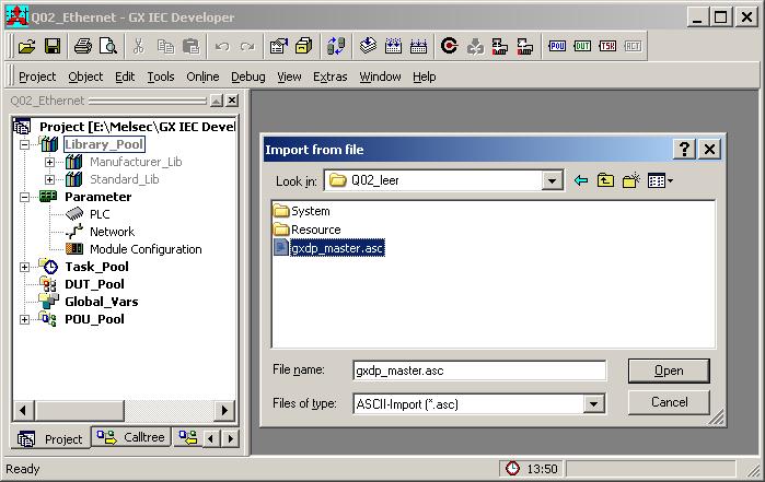
23 Installation 20 download the configuration to the master module 9. create the program code for GX IEC Developer (GID) by selecting 'POU for GX IEC Developer' 10. import the POU in the GID project
24 21 GX Configurator-DP
25 Main Menu 4 22 Main Menu Starting GX Configurator-DP Select GX Configurator-DP from the Windows Start menu. The default shortcut is Start -> Programme -> MELSOFT Anwendungen -> GX Configurator-DP > GX Configurator-DP 7.03 Main menu The main menu offers the following pull-down menus. The menu item Window is only available, if a project is open. if no project is open if a project is open Main Menu Items Description Project menu for creating, opening and saving project files Tools menu for external tools View menu for configuration of the application Window menu for listing the open project windows Help menu for help and application information The items in the open pull-down menus can be reached via mouse or keyboard. The underlined character will start the function. In addition there are some menu items which may be started using predefined hot keys. Shortcuts Shortcut Function Ctrl + 'N' create new project Ctrl + 'O' open existing project Ctrl + 'S' save modified projects Alt + F7 show list of open project windows
26 GX Configurator-DP Project Menu After having started the GX Configurator-DP software, this is the first menu to work with. With the help of this menu you can create a new or load an existing project. The menu offers the following commands: Command Description New Starts a new project Open Opens an existing project Close Closes the active project Save Saves the active modified project Save As Saves the active project under a new name Recent Files Opens one of the latest used projects Exit Ends the application Command New The menu command New is used to create a new project.
J71B92D FX: FX3U-64DP-M Read from PLC reads the list of modules from the connected PLC and displays them in a list, so the")
27 Main Menu Name Description Choices / Setting range 24 Default CPU Series selection of CPU series, in which the PROFIBUS module is used Qn, QnA, FX Qn MELSEC Module Type module types supported by the selected CPU series Qn: QJ71PB92V QJ71PB92V QJ71PB92D QJ71PB93D QnA: A(1S)J71B92D FX: FX3U-64DP-M Read from PLC reads the list of modules from the connected PLC and displays them in a list, so the user can select module type and head address - PLC Project - select the project file of the corresponding GD/GID project. The project directory is used to locate the image file for autorefresh parameter settings (iparam.wpa) in the Resource subdirectory of the GD/GID project. This file is updated by GXDP, if the Autorefresh -option has been
28 25 GX Configurator-DP Name Description Choices / Setting range Default selected Browse opens the file dialog to select the GD/ max. 255 characters GID project file - Comment an optional comment text of max. 255 max. 255 characters characters length, which describes the project - Cancel Close dialog and discard changes - Next proceeds to next wizard page Default button Default sets CPU series and module type to their default settings, clears PLC project path and comment field MELSEC Module Type: select the type of module for the project The following table shows the supported project types and marks the types included in the selection list depending on the type of PLC, which has been selected. Module Type Qn A(1S)J71PB92D (PROFIBUS DP V0 Master) FX x QJ71PB92D (PROFIBUS DP V0 Master) x QJ71PB92V (PROFIBUS DP V1/V2 Master) x FX3U-64DP-M (PROFIBUS DP V1 Master) QJ71PB93D QnA x x Read from PLC: when this button is pressed, the user must first select the type of the PLC CPU, in which the PROFIBUS module is located. The entries in the CPU series list depend on the CPU series selected in the Select Module Type dialog, e.g. if Qn has been selected, the CPU Series list contains the entries Qn QnPH QnPRH

29 Main Menu 26 The list CPU type contains the CPU types of the selected series. Pressing the button Transfer Setup in the dialog CPU Type Selection opens the transfer setup dialog. When this dialog is closed by pressing OK, the latest transfer settings are always stored in the same file in the GXDP installation directory. These settings are used as default for the next new project, if the CPU series stays the same. If the CPU series is changed, e.g. by first creating a QJ71PB92V project and then a project for the FX3U-64DP-M, the transfer setup is converted to match the new CPU series. After this the transfer setup editor is opened, so the user can adjust the settings of the PLC connection. For a detailed description of the transfer setup dialogs see the section Transfer Setup. After leaving the transfer setup editor, a connection to the PLC is attempted. If the connection fails, an error message is displayed. If the connection can be established, the list of modules in the PLC rack is displayed.
30 27 GX Configurator-DP Name PLC Rack Description Choices / Setting range Column Contents Slot 0-based index of the PLC slot Starting I/O number offset of the module-specific X/Y devices (empty for FX) Default Module Type identifier of module type retrieved name from GXDP product database OK Close dialog and save selected module type and starting I/O number Default button Cancel Close dialog and discard selection - If the user selects a module supported by GXDP, the corresponding module type is set in the combo box. The starting I/O number of the selected module is used as default for the starting I/O number of either master or slave instead of the default I/O number 0x00. 'New Project Wizard' for Master Projects If a master module has been selected in the previous wizard page, the next pages provide access to the master configuration and are identical to the 'Master Parameters Wizard'.

31 Main Menu 28 Select the baudrate for the PROFIBUS network and other parameters. For a detailed description see Master Settings.
32 29 GX Configurator-DP This dialog is opened by pressing the button Bus Parameters in the Master Settings dialog. For a detailed description see Bus Parameters. Enter the CPU device addresses of the transfer buffers for exchanging data between CPU and master module. For a detailed description see CPU Device Access. 'New Project Wizard' for QJ71PB93D Projects If a QJ71PB93D module has been selected in the previous wizard page, the next pages provide access to the Q-slave configuration and are identical to the 'Slave Parameters Wizard'.


33 Main Menu 30 Enter the starting I/O number and the FDL address of the slave module. For a detailed description see Q-Slave PROFIBUS Settings. Enter the CPU device addresses of the transfer buffers for exchanging data between CPU and slave module. For a detailed description see Q-Slave Autorefresh Settings. Command Open The menu command Open allows to open a project, which has previously been saved.
34 31 GX Configurator-DP The Open dialog box lists only files of the following type: *.dp2: old or current GXDP project file format *.dpx: old GXDP project file format for QJ71PB93D slave modules The current version can open project files created with previous versions 4.0 or newer of GX Configurator-DP. Previous versions cannot open GX Configurator-DP 7.03 project databases. Note: *.DP-projects generated with software versions previous to GX Configurator-DP 4.0 cannot be opened. Conversion of Old Projects If a project file created with an older version of GX Configurator-DP is opened, the user is informed that the file must be converted. If the project file cannot be converted, a list of more detailed error messages is displayed.

35 Main Menu 32 The error messages can be saved in an ASCII file by selecting the 'Save' button. If the conversion of a PROFIBUS master project fails, missing GSD information is in most cases the reason. GXDP searches the following files for GSD information in the following order: 1. project file 2. global GSD device database 3. GSD export file (same file name as the project, but extension '.ext') If the option 'GSD database has priority' is enabled, the global GSD device database is searched first: 1. global GSD device database 2. project file 3. GSD export file (same file name as the project, but extension '.ext') The second sequence may be helpful in rare situations, where the GSD information in the project is inconsistent with the project configuration. If a slave type, specified by a combination of the GSD entries 'Model_Name', 'Ident_Number' and 'Revision', cannot be found in any of the three files, the conversion stops and the error message lists the missing slave types. The user should add the corresponding GSD files to the global device database and retry to convert the project file. If the project file could be converted, but settings had to be changed, the user can review the actions taken during the conversion in a list.

36 33 GX Configurator-DP Note: the converted project overwrites the old project file, when it is saved. To preserve the original file, a copy of the file with the extension '.backup' is created. Update GSD Information in Project If the option 'GSD database has priority' has been selected in 'Options', the user can select slave types, which exist in both the project file and the GSD database. Name Description Slave Type List list of slave types, which exist in both the GSD database and the project file Select All toggles the selection of the slave types OK closes the dialog and replaces the GSD information of the selected slave types in the project Choices / Setting range Default Default button


37 Main Menu Name Description Cancel closes the dialog and continues opening the project without replacing GSD information Choices / Setting range 34 Default - If the user presses 'OK', the GSD information for the selected slave types in the project file is replaced with the corresponding GSD information from the GSD database. If the user presses 'Cancel' or does not select any slave type, no GSD information is updated and the project is opened using the GSD information already contained in the project file. Check of GSD Consistency When a project file for a PROFIBUS master is opened, GXDP searches the GSD information in the project file for the slave and module types used in the project configuration. If GSD information is missing for a slave or a module type, the following message is displayed. If the user selects No, the project cannot be opened. If the user selects Yes, the list of inconsistencies is displayed. If errors have been found, the user can only view the messages, but cannot proceed with opening the project. The OK button is therefore disabled.


38 35 GX Configurator-DP The reason for such inconsistencies can be an import of incompatible GSD information from the central GSD database (see GSD Update ) when opening the project. In this case the project should be opened again without importing the GSD information from the central database. Command Close This menu command closes the active project. Command Save This menu command is used to save a modified project. The project will be saved to the assigned file name. If no file name exists (e.g. new project) the standard dialog box for Save As will be opened. Remove GSD Information When saving a master project, the user can have all unused GSD information removed from the project file in order to reduce its size. If the project file contains GSD information for slave types, which are not used in the project, the user is asked, whether to remove the data. If the user agrees, the GSD information is removed from the project file. If the user does not want to be asked each time a project is saved, the checkbox 'Do not show this message again' in the message box can be set. In this case the same action (removing or keeping unused GSD information) is performed each time, until the application is restarted. Command Save As This menu command is used to save a project with a new assigned file name. This command uses the dialog box for file saving.

39 Main Menu 36 Files can only be saved in the 'dp2' format. Command Recent Files The pull-down menu shows you the last used projects. You can open a project file by selecting the corresponding entry. Command Exit You can use this menu command to quit the software. If an open project has been modified and has not yet been saved the following message appears: If you want to save the last changes before leaving and ending the GX Configurator-DP software choose <Yes>. If you choose <No>, all modifications to the respective project are lost. 4.2 Tools Menu The Tools menu offers the following commands:

40 37 GX Configurator-DP Command Description GX Configurator-ST starts GX Configurator-ST for configuration of ST1H-PB 'Slice I/O' slaves Options edit general (i.e. project independent) application settings GX Configurator-ST This item starts GX Configurator-ST (GXST), the configuration tool for the ST1H-PB slave devices. This menu command is enabled, if GXST is installed, i.e. the corresponding executable file can be found. With GXST you can operate settings and graphically monitor ST1H-PB. GXST shows status and error information for the ST slave and its modules. It provides test functions and an user interface for changing parameters of the device. The GX Configurator-ST runs as a separate application with its own entry in the task list and must be closed separately. However, when GX Configurator-DP is closed, it displays a warning message in case GX Configurator-ST is still running. Options The menu item Options provides access to general (i.e. project independent) application settings. It opens the Options dialog, which lists the application settings in a property grid. Name Description Choices / Setting range Default GSD database has priority when set to True, the user can replace existing GSD data in the project file. Each time a project file is opened, a list of the slave types, which exist in both the project file and the central GSD database, is displayed. The user can select the slave types, of which the information should be replaced. true, false false OK Close dialog and save settings to become effective after next change Default button Cancel Close dialog and discard changes -
41 Main Menu View Menu In the View menu you can select the following menu commands: Command Description Toolbar Shows or hides the application s toolbar. Status Bar Shows or hides the application s status bar. These menu commands toggle the display of the toolbar and the status bar. A check mark in front of the command indicates that the corresponding bar is activated. Command Toolbar The toolbar is a collection of buttons, which provide direct access to the most frequently used functions. Its appearance depends on the type of the open project. Toolbar, if no project is open Toolbar, if project is open and all functions are supported by master Icon Function Available for 1 Project -> New all 2 Project -> Open all 3 Project -> Save all 4 GSD Device Database master projects 5 Download to Module all 6 Transfer Setup all 7 POU for GX IEC Developer master projects 8 Start/Stop PROFIBUS all 9 I/O Mapper master projects 10 Help all Command Status Bar If this command is marked, the standard Windows status bar is displayed at the bottom of the application window. The status bar shows a short message of the menu item under the mouse
 2.")
42 39 GX Configurator-DP cursor and the status of certain keyboard keys. Project Infobar The infobar is a window of GXDP, which is displayed above the standard Windows status bar. It displays important information, which is specific to the active project. The following information is displayed in the infobar 1. the status of the PLC connection ('connected', 'not connected') 2. the name of the currently selected transfer setup 3. the type of the CPU selected in the transfer setup 4. the last path of the exported POU (only if 'POU for GX IEC Developer' has been called since the project has been opened) 4.4 Window Menu The 'Window' pull-down menu lists the names of the open projects. Selecting an entry activates the corresponding project window.

43 Main Menu 4.5 Help Menu The 'Help' pull-down menu provides access to the online-help and version information of the application. Command Purpose Help Topics Opens the online help About Displays version information of the application Command Help Topics This item opens the online help in a separate window. Additionally the context-specific help is opened by pressing F1 in a window of the application. Command About... The about box show the software name and version as well as the copyright notice. 40


44 41 5 GX Configurator-DP PROFIBUS Configurator Tasks Using the Task Panel The PROFIBUS Configurator Tasks window offers the user project specific shortcuts to manage a PROFIBUS DP project. The shortcuts are grouped into types of actions. With the button in the group header the task items can be collapsed so that only the header is visible to the user. collapsed task group expanded task group If operated via the keyboard the up/down cursor keys move the focus within the task panel. The focused task item is marked with a dotted frame. Pressing the space bar triggers the focused item. To expand/collapse a task group via the keyboard the caption of the task group must have the focus. The expand/collapse state is then toggled via the spacebar.

45 PROFIBUS Configurator Tasks 42 Some entries, which are frequently used, show icons before the text. These icons exist in the toolbar as well. Clicking the icon in the toolbar has the same effect as selecting the corresponding entry in the task panel. Tasks for Master Projects The available items in the task panel depend on the project type and application state. The task panel contains the following groups of items Online Tasks
 Download to Module Download the configuration from")
46 43 GX Configurator-DP 5.1 Setup Tasks Export Tasks Documentation Diagnostics Online Tasks Command Description Transfer Setup Define the network connection type (PC to PLC) Download to Module Download the configuration from the current project to the connected module Upload Configuration Image Read the binary configuration image from the master and store it in a file Download Configuration Image Download the configuration image taken from the specified file to the master module Verify Upload the existing configuration from the module and compare it with the current project Start/Stop PROFIBUS Start or stop the cyclic DP data transfer Set Slave Address Change the FDL address of a slave online This function is only available for QJ71PB92V and FX3U64DP-M Transfer Setup This item opens the dialog for managing the communication settings of the PLC connections. For a detailed description see Transfer Setup. Connection Handling for Online Functions If any of the functions listed in 'Online Tasks' is started, the settings of the currently selected transfer setup are used to connect to the target PLC and the PROFIBUS module within the PLC. If the connection to the target PLC fails for any of the 'Online Tasks', the user is informed with an error message.

47 PROFIBUS Configurator Tasks 44 The user can now choose to open the transfer setup to change the transfer settings and try again. If the user selects Yes, the transfer setup dialog is opened. If the connection to the PLC is established, GXDP tries to locate the module at the specified starting I/O number. If there is no module at the given starting I/O number or if the module found does not match the current module type of the project, the user is informed and asked, whether he wants to select the module online. If the user presses 'OK', the list of modules is read from the PLC and displayed in a list. If the user selects a module matching the project type and presses OK, the respective online function is executed.

48 45 GX Configurator-DP Download to Module When the user selects the Download to Module task item or toolbar button, the user is asked to select the items for download. Name Items List Description Choices / Setting range Default Download PROFIBUS configuration selected / not selected selected Update Autorefresh settings selected / not selected selected selected / not selected not selected available only for Q-series projects, if Autorefresh has been selected in 'CPU Device Access' Remove Autorefresh settings for the same module type available only for Q-series projects Select All selects / deselects all items selected / not selected / selected indeterminate OK close dialog and start update of the selected items. Default button Cancel close dialog and do not download anything - (same as pressing OK with no item selected) The selectable items, which are listed in the dialog, depend on the project type and settings. 1. Download PROFIBUS configuration Download the PROFIBUS settings to the connected module. 2. Update Autorefresh settings Add or update the autorefresh settings for the module with the configured head address.
49 PROFIBUS Configurator Tasks Remove Autorefresh settings for the same module type Delete existing autorefresh settings for the same module type. This option should be set, if for example a PROFIBUS module has been moved to a different slot or the I/O assignment has been changed. When the CPU cannot find the specified module type at the specified head address, its signals an error. GXDP only updates the autorefresh settings for the head address specified in the 'Master Settings'. Existing autorefresh settings for other head addresses remain unchanged. The effects of this option depend on the state of the option 'Update Autorefresh settings'. option 'Update Autorefresh settings' is selected: autorefresh settings for modules of the same type as used in the project, but with different starting I/O numbers, are removed option 'Update Autorefresh settings' is NOT selected or not available: all autorefresh settings for modules of the same type as used in the project are removed, including settings for the starting I/ O number currently configured If the user presses OK, the selected items are downloaded respectively updated. If the option 'Download PROFIBUS configuration' has been selected, the autorefresh settings are only updated, if the previous configuration download has been successful. While the configuration image is written to the module, a progress bar is displayed. This operation cannot be interrupted by the user to ensure a consistent download. A download to FX master modules can only be performed, if the CPU is in 'STOP' state. If the download has been successful, the following message is displayed. For A(1S)J71PB92D modules the message contains an additional remark about the mode hardware switch.


50 47 GX Configurator-DP Note: for A(1S)J71PB92D modules the user must set the correct operation mode (0 or E) with the switch on the front of the module. The module will take over the setting of the mode switch after a CPU reset. Download to project module type only Note: a download is only possible, if the type of the connected module matches that of the project. If the user wants to download the project to a different module type, the project must first be converted to the type of the connected module. This is done by selecting the Change Master Type menu item. Autorefresh Update If the user has selected the 'AutoRefresh' option, the autorefresh settings are updated, after the configuration has successfully been downloaded to the PROFIBUS master module. The (online) update of the autorefresh settings on the CPU is only possible, if the CPU is stopped. The CPU status is checked and, if the status is not 'STOP', the user is asked, whether the CPU can be stopped. After stopping the CPU the autorefresh settings on the CPU are updated. Existing autorefresh settings on the CPU for the same head address as the current master module are overwritten with the settings for the master, existing settings for other modules remain unchanged. If the CPU had been stopped prior to the update, the user is asked whether to start the CPU again.
. After the GID/GD project has been updated, the path of the updated IParam file is displayed.")
51 PROFIBUS Configurator Tasks 48 The autorefresh settings in the parameter file of the corresponding GID/GD project are also automatically updated, if the path to an existing GID/GD project has been set (see 'Project Properties'). After the GID/GD project has been updated, the path of the updated IParam file is displayed. Autorefresh Settings on Remote I/O GX Configurator-DP cannot online update the autorefresh settings in Q-series Remote I/Os. For Remote I/Os the settings must be updated in the corresponding GID/GD project file and then be updated in the Remote I/O itself with GID/GD. If the user downloads to a Remote I/O and no GID/GD project path has been set, the user is prompted to enter the path to the IParam image file, which should be updated. In GID/GD projects the IParam image file is named 'iparam.wpa' and located in the subdirectory

52 49 GX Configurator-DP 'Resource' of the project directory. Download to FX The FX3U-64DP-M PROFIBUS master can only be updated, if the CPU is stopped. If the CPU is in 'RUN' state, the user is asked, whether the CPU can be stopped. If the user agrees, the CPU is stopped and the configuration is downloaded. After the download has completed, the CPU can be restarted. Download to QnPRH Redundant System Type 1: QnPRH system with redundant PROFIBUS masters


53 PROFIBUS Configurator Tasks 50 Type 2: QnPRH (2nd) system with single PROFIBUS master in expansion backplane The QnPRH redundant PLC system can be operated with a dual (redundant) PROFIBUS network. The control CPU provides access to the active PROFIBUS master module, while the standby CPU has a second master, which becomes active, when the standby system takes over the task of the control system. Besides in a redundant configuration a QnPRH CPU can also be used as a single standalone PLC or combined with another QnPRH PLC as a dual PLC system with both CPUs connected via a special communication link ( tracking cable ). To update both masters in a QnPRH system as well as the autorefresh settings in both CPUs, the redundant system must be in Separate mode and device tracking for the X/Y devices must be disabled. GXDP therefore switches the redundant system to Separate mode, if it is in Backup mode. It also disables device tracking, if the system is in Backup or Separate mode. After completing the download to both masters and having updated the autorefresh settings, GXDP sets the system back into its original state. The new QnPRH 2nd generation PLC supports a new type of expansion backplane, which is directly connected to the backplanes of both QnPRH CPUs. The expansion backplane is mapped into the I/ O range of the respective control system. The modules in the expansion board are not visible to the standby CPU. The QnPRH expansion board allows to operate a redundant PLC without having each network module twice. Mode GXDP Handling The PROFIBUS configuration is downloaded to both PROFIBUS modules (redundant network setup) or the single PROFIBUS module (expansion rack setup). The autorefresh settings are updated in both PLCs. Therefore the system must be temporarily switched to 'Separate' mode. Backup Separate User must choose whether to update both systems (pressing Yes ) or only the directly connected system (as selected in transfer setup) (pressing No ). If Cancel is pressed, nothing is updated.

54 51 GX Configurator-DP Mode GXDP Handling In Debug mode only the PLC selected in the transfer setup is updated. Debug Note: if device tracking is disabled, this applies only to the default tracking block controlled by SM1520. If the user has specifically configured device tracking and included the X/Y devices of the intelligent function modules, the communication may fail. Verify This function verifies the settings of the selected project with the current configuration of the module. For PB92D masters a warning is displayed to inform the user that the data exchange on the PROFIBUS network will be stopped. The current configuration is read from the module and compared with the configuration created from the current project. If both settings match, the following message box is displayed. If the settings differ, the following message box is displayed. More detailed information on which parts of the settings are different, is not provided.


55 PROFIBUS Configurator Tasks 52 In case any problems occur, for example when reading the configuration from the module, a general error message is shown. Note: for Q-series master modules the autorefresh settings are not compared. Verify on QnPRH Redundant System Before uploading the configuration from the PROFIBUS master module(s) and comparing it with the project, the user is asked whether to proceed. The query depends on the redundancy mode, however it does not depend on whether there are one or two master modules. Mode GXDP Handling If there are two masters, the configuration of both masters is uploaded and compared. If there is only one master, the configuration of that master is uploaded and compared. Backup If there are two masters, the configuration of both masters can be uploaded and compared. The user can also decide to verify only the configuration of the master in the directly connected PLC rack. If there is only one master, the user's choice has no effect. Separate In this mode only the configuration of the master in the connected PLC is verified. Debug

56 53 GX Configurator-DP If the configuration of two master modules in a redundant PLC system is verified, the result shows for each of the two master modules, whether its configuration matches the current project or differs from it. If the configuration of both masters matches the project: If the configuration of one or of both masters differs from the project: If there is only one master module in the redundant system as in a QnPRH (2nd) with a single expansion backplane, only the configuration of this master is compared with the project. Upload Config. Image The user is prompted for a file, in which the configuration image should be stored.
57 PROFIBUS Configurator Tasks 54 For PB92D masters a warning is displayed to inform the user that the data exchange on the PROFIBUS network will be stopped. The current configuration is read from the master module and stored in binary format in the file, which the user has selected. Information stored in the PLC CPU like autorefresh settings or POU code is not retrieved. The user is informed after the successful upload or gets an error message, if it fails. The configuration image can be used to configure another master module, if the original GXDP project file is not available. The configuration image is downloaded to a master with the 'Download Config. Image' function. Note: the information read from the master module cannot be used to create a GXDP project file.
 or the corresponding export function of GXDP (see 'Export -> Config. Image' ). This configuration must be compatible to the module type set in the current project.")

58 55 GX Configurator-DP Download Config. Image The user must first select a file with a configuration image created by a previous upload (see 'Upload Config. Image') or the corresponding export function of GXDP (see 'Export -> Config. Image' ). This configuration must be compatible to the module type set in the current project. GXDP reads the configuration image from the file and downloads it to the master module. The user is informed after the successful download or gets an error message, if it fails. Start/Stop PROFIBUS This item is used to manually start or stop the PROFIBUS DP cyclic data transfer of DPV0. The current status of the connected PROFIBUS master is checked. If there is no active data transfer, the user is asked to confirm starting the transfer. If the data transfer is active, the user is asked to confirm stopping the transfer. The cyclic data transfer is started respectively stopped. If a PLC program is running, which starts the data transfer, while the user tries to stop the data transfer, the operation fails. An error message is displayed and the user is informed of the possible access conflict between PC and PLC program. Set Slave Address This function is provided to change the FDL address of a slave device online. Note: this function is only available for QJ71PB92V and FX3U-64DP-M and must be supported by the slave. The appearance of the dialog, which is opened when selecting the Set Slave Address item,
 Slave is selected If the master is selected, the user must enter the current address of the slave. For QJ71PB92V also the ident number must be entered.")

59 PROFIBUS Configurator Tasks 56 depends on the master type and the node, which is selected in the project tree. for QJ71PB92V (Ident-No. must be entered) Master is selected for FX3U-64DP-M (Ident-No. not required) Slave is selected If the master is selected, the user must enter the current address of the slave. For QJ71PB92V also the ident number must be entered. If a slave is selected, the current slave address and the ident number are taken from the project settings and both fields are read-only. The service requires the current and the new FDL address as parameters, together with the ident number of the slave, which is checked to ensure that the correct slave is accessed. The current address and the ident number are taken from the slave, which has been selected in the project tree. By pressing Set the request is sent to the slave. The response (success or failure) from the slave is displayed in the Messages field. Request to change FDL address has been sent. QJ71PB92V Note: A positive response does not imply that the slave has actually changed its address. This must be verified by the user with other means (e.g. using the 'Live List' function of FX3U-64DP-M). FX3U-64DP-M

60 57 GX Configurator-DP Failure Note that FDL address cannot be changed, if data transfer is active Name Description Choices / Setting range Old address current FDL address of the slave Default If a slave is been selected in the project tree, the address of that slave is set as default, if the master is selected, the user can enter any valid address New address the new FDL address to be set in the slave Ident.-No. (hex) the identification number is used to verify that the correct slave is addressed. the ident number (range 0x0000 0xFFFF) This parameter is only required for QJ71PB92V. If a slave has been selected in the project tree, the ident no. of that slave is inserted, if the master is selected, the user must enter the correct ident number (for QJ71PB92V only) in hex format. The FX3U-64DP-M will internally determine the ident number for the specified old address and insert it into the PROFIBUS request. Messages the result of the operation (success or error message) Set sends the SetSlaveAddress request Default button Close Close dialog -


61 PROFIBUS Configurator Tasks Setup Tasks Command Description Change Master Type Convert the project to a different type of master module GSD Device Database Open the trees with the device types in the global device database and in the project file Project Properties Open a dialog to select the GID/GD project and to set the comment I/O Mapper Open the editor for defining the structures for access to slave inputs/ outputs Note: this entry is disabled, if 'slave specific' transfer has been selected in CPU Device Access Devices for Slave-Specific Transfer Edit the device addresses for slave-specific data transfer Note: this entry is only enabled, if 'slave specific' transfer has been selected in CPU Device Access. Slave-specific transfer is only supported for Q-series PROFIBUS master modules in combination with autorefresh. Change Master Type With this menu item the user can change the current project to a different type of master module. Name CPU Series Description selection of CPU series, in which the PROFIBUS module is used Choices / Setting range Qn, QnA, FX Default Qn
J71B92D FX: FX3U-64DP-M OK convert the project to the selected type and close the dialog Cancel discard changes and close the dialog Default button If")

62 59 GX Configurator-DP Name MELSEC Module Type Description Choices / Setting range module types supported by the selected CPU series Qn: Note: the current module type of the project is not listed QJ71PB92D Default QJ71PB92V QJ71PB92V QnA: A(1S)J71B92D FX: FX3U-64DP-M OK convert the project to the selected type and close the dialog Cancel discard changes and close the dialog Default button If the project can be converted, a message is displayed. If the change of the master type implies a change of the CPU type, the user is also reminded to adjust the transfer settings. The project conversion may fail, if the current configuration is not supported by the new master, for example because of the number of slaves when converting a project from QJ71PB92V to QJ71PB92D. GSD Device Database Opens the tree views for the device types stored in the global device database and in the project file. For a detailed description see 'GSD Device Database'. Project Properties This dialog provides access to project specific properties
63 PROFIBUS Configurator Tasks Name Description Choices / Setting range PLC Project select the project file of the corresponding GD/GID project. The project directory is used to locate the image file for autorefresh parameter settings (iparam.wpa) in the Resource subdirectory of the GD/GID project. This file is updated by GXDP, if the Autorefresh -option has been selected Browse opens file dialog to select the GD/GID project file max. 255 characters - Comment an optional comment text of max. 255 characters length, which describes the project max. 255 characters - OK Close dialog and save changes Default button Cancel Close dialog and discard changes - 60 Default - I/O Mapper Opens the table for defining 'Data Unit Types' (DUTs) and global variables for access to slave input and output data. For a detailed description see 'I/O Mapping'. Devices for Slave-Specific Transfer The item is only accessible, if slave-specific transfer has been selected in CPU Device Access. It opens a modal dialog, which lists the slaves configured in the project sorted by FDL address along with their respective input and output size. The user can assign a device address to each input and output area of slave. The contents of these devices are exchanged with the input and output areas in the buffer memory of the master via autorefresh.
 Input Device device address to transfer inputs to Output Device OK Cancel device address to transfer outputs from Default input and output devices")
64 61 GX Configurator-DP Name Slave List Description Choices / Setting range Column Contents Slave name user-assigned name of the slave I/O Word Size input and output size of the slave in words (odd byte sizes are rounded up to the next word boundary) Input Device device address to transfer inputs to Output Device OK Cancel device address to transfer outputs from Default input and output devices must be word devices and must be supported by autorefresh if the slave has no inputs or outputs, the corresponding device address input field is disabled Close dialog and saves entered device addresses Default button Close dialog and discard changes - Note: slave-specific transfer is only available in combination with autorefresh and not together with I/ O mapping. This means that no POU/user library is generated for slave-specific transfer GSD Device Database The device database contains information about PROFIBUS DP slave device types from MITSUBISHI ELECTRIC or 3rd party manufacturers. New device types are added to the database by parsing the GSD file, which accompanies the device. When a slave is added to a PROFIBUS master configuration project, the GSD information for the slave is copied from the global GSD database to the project file. This enables the user to edit a project file on a different system, without having to add the device types to the respective global database again. Due to these procedure there are actually two databases with GSD device information, the global database under the installation directory of GXDP and the project file. GSD Database Device Tree A device database is accessed via a tree-like user interface. The GXDP user interface contains two

65 PROFIBUS Configurator Tasks 62 device tree windows, one for the global GSD database, one for the GSD information in the project file. You can switch between the two GSD data trees by selecting the corresponding tab. Caption Global GSD data Tab Caption Project GSD data Tab If a slave type from the 'Global GSD data' tree is added to the project and the GSD information for that type is missing in the project, the GSD information is added to the project and a node for the type is inserted in the 'Project GSD data' tree. The device groups are represented by folders, with the device types of the group as child nodes. The tree node of a device type shows the bitmap of the device and its type name. If no specific bitmap has been assigned to the device, the default bitmap is displayed. The device tree for the global GSD database provides a context menu with functions to modify the database. Slave selected in 'Global GSD data' Group selected in 'Global GSD data' Slave selected in 'Project GSD data'
, GSD export file (. ext) or GXDP project file (.")
66 63 GX Configurator-DP Menu Item Description Add Slave to Project add the selected slave to the project Note: this menu item has the same effect as adding a slave via drag&drop Add GSD File opens a file dialog to select a GSD file, which is to be parsed and added to the database Import GSD Database import device types from a GSD database (.mdb), GSD export file (. ext) or GXDP project file (.dp2) Properties opens a dialog to view properties of the selected slave type. In the 'Global GSD data' tree some of the properties can be changed, e.g. the bitmap, in the 'Project GSD data' tree the properties are readonly Remove Type removes the slave from the database Add Slave to Project To add a slave of the selected type to the project, the user can either select the corresponding menu item from the context menu of the GSD tree or move the mouse pointer to the project tree while keeping the left mouse button pressed. A slave can be added from the Project GSD data and the Global GSD data tree. If a slave type is added from the Global GSD tree and GSD information for the selected type is missing in the project file, the GSD information is transferred from the global GSD database to the project file. If the slave type is already in the project file, the information in the project file is not changed. When the project is edited, the GSD information is always taken from the project to ensure data consistency. Changes made to Global GSD data will only have an effect on an existing project, if the GSD information is updated, when the project is opened. Please see 'Update GSD Information in Project'. To make the user aware of the potential conflict of the same slave type existing in both GSD databases, a message box is displayed, if the user adds a slave from Global GSD data to the project, while GSD information of the same slave type already exists in the project.

67 PROFIBUS Configurator Tasks 64 By marking the Do not show this message again checkbox, further display of this message is avoided as long as GXDP is running. When GXDP is restarted, this mark is cleared and the message is displayed again. Add GSD File A GSD file can be added to the database by selecting the item 'Add GSD File...' from the context menu. A file dialog appears to select the GSD file. When leaving the dialog with <OK>, the GSD file is parsed and its contents stored in the GSD database. The GSD file itself is no longer required. If the GSD file references a bitmap file for the slave device, GX Configurator-DP automatically tries to load the respective bitmap file and store it in the GSD database. In case the file is not found a default bitmap is used instead. The bitmap can be replaced with a device specific bitmap later on. The PROFIBUS standard specifies the following format for the bitmap file: Width 70 pixels Height 40 pixels Colors 16 File Extension dib, bmp Only bitmaps that match the requirements in the table above should be used. Other bitmaps with other sizes and color depths can be used, but may not be correctly displayed.
68 65 GX Configurator-DP When the GSD file has been selected, you will be asked to confirm the operation. If you confirm, the contents of the GSD file are parsed and added to the GSD database. Please ask the manufacturer of the slave device for the matching GSD file. Import GSD Database The GSD information for device types, which are missing in the GSD database, can be imported from an old GSD database (gsd_db.mdb), a GSD export file (*.ext) or a GXDP project file (.dp2). Note: it is strongly recommended to parse the GSD files for the slave devices using the 'Add GSD File' function instead of importing the parsed GSD information from older databases. This ensures that all GSD information supported by this version of GXDP is extracted from the GSD file. Selecting the 'Import GSD Database' item in the context menu opens a file dialog to select the file

69 PROFIBUS Configurator Tasks 66 containing the GSD information to be imported. If all device types found in the selected file already exist in the GSD database, the following message is displayed If there are missing slave types, which can be imported, these types are displayed in a list. Name Description Choices / Setting range Default Slave Type List list of slave types, which exist in the file selected for import, but not in the GSD database Select All toggles the selection of the slave types OK closes the dialog and adds the GSD information of the selected slave types to the GSD database Default button Cancel closes the dialog - Device Type Properties When the item 'Properties...' is selected in the context menu, the 'Device Type Properties' dialog is displayed. If opened in 'Project GSD data', the device settings cannot be changed and the corresponding controls in the dialog are disabled.
 read-only - Ident-No.")
70 67 GX Configurator-DP Name Description Choices / Setting range Default Vendor company name of the vendor (usually the value of the keyword Vendor_Name in the GSD file) read-only - Revision the version of the device respectively GSD file (usually the value of the keyword Revision in the GSD file) read-only - Ident-No. a number assigned by the PNO for unique read-only device type identification. The value is taken from the entry Ident_Number in the GSD file. - GSD-/DDB-File name of the GSD file Bitmap shows the slave-specific bitmap for the selected state, which has been stored in the database. read-only Different bitmaps can be assigned to the following states: Normal Diagnostics Special Function GXDP only uses the Normal bitmap for
71 PROFIBUS Configurator Tasks Name Description Choices / Setting range 68 Default display. Replace Bitmap opens a file dialog for selecting the bitmap file to be assigned to the selected state in 'Global GSD data': enabled in 'Project GSD data': disabled Bitmap-File name of the bitmap file read-only Slave Family allows to alter the slave family set by the in 'Global GSD GSD file, under which the slave is located in data': enabled the tree in 'Project GSD data': disabled Set Byte Order for User Parameter selects the byte order for user parameters of types short and long (signed and unsigned). This setting should normally never be changed, because PROFIBUS specifies big Endean, which is the default Low byte first / High byte first High byte first in 'Global GSD data': enabled in 'Project GSD data': disabled OK Close dialog and save changes Default button Cancel Close dialog and discard changes - Replace Device Bitmap The user can replace the existing bitmap of the slave by pressing the button 'Replace Bitmap'. This opens a file dialog, in which a file with a new bitmap can be selected. The device database can store three different bitmaps for a device type, used for different states of the device. Via the group of radio buttons the state, in which the bitmap is used, is selected. The GSD standard specifies bitmaps for: normal operation (this is used in the GX Configurator-DP editor) diagnostic status special operations mode When a bitmap is replaced, this applies only to the selected state. Change Slave Family / Group When a slave device is added to the GSD database, it is placed in the slave family, which is specified in the GSD file. If no slave family has been specified, the slave is placed in the 'General' group. The user can move the slave to a different group by selecting a group in the 'Slave Family' list and pressing <OK>. Change the Byte Order of User Parameters The default setting for the byte order is High byte first and should normally never be changed from its default setting, because incorrect user parameter settings may have unforeseeable effects on the slave. To make the user aware of this a message box is displayed, whenever the user changes the byte order in the dialog

72 69 GX Configurator-DP If the user confirms, the byte order is changed, but will only effect new projects. Because existing GXDP project files contain a copy of the GSD information, the change of the byte-order in the GSD database has no effect on the existing project. The byte order of user parameters must not be confused with the byte-order of the slave I/O data. Warning: Please consult the vendor of the slave before changing the byte order as incorrectly encoded user parameters can have unforeseeable effects and may cause malfunctioning or damage. DPV1 Support With DPV1 the meaning of the first three bytes of the slave user parameters is specified. Some slaves, especially older models, have placed slave-specific parameters in this range of the user parameters. If a slave supports the standard DPV1 user parameter format, the GSD file should contain an entry 'DPV1_Slave=1'. With some slaves this entry is missing in their GSD file, although the slave require DPV1 support to be activated in the master. In these cases the entry 'DPV1_Slave=1' must be inserted in the GSD file using a standard text editor (e.g. 'notepad'). After saving the modified file it must be added again to the GSD database. GSD Update If you try to add a GSD file to the device database for a device, which already exists, a warning is shown. You can either choose to add the device information with a device revision or type name different to that of the existing device or choose to replace the existing entry. Note: please be aware that GXDP uses the combination of ident number (GSD keyword 'Ident_Number') model name (GSD keyword 'Model_Name') revision (GSD keyword 'Revision') to uniquely identify a device. Two GSD files must differ in at least one of these three items in order to both be added to the GSD database. If you choose to replace the GSD file, internally the existing entry is deleted first and then the new GSD file is parsed. This will however not effect existing projects, which already use the device type and where the GSD information is part of the project file.
73 PROFIBUS Configurator Tasks 70 Removing Type A device type can be removed from the database by selecting the 'Remove Type' item from the context menu. Before removing the device the user is asked to confirm the operation. This deletes only the entry in the GSD database. It does not delete the GSD and bitmap files for that device. These files have to be removed manually I/O Mapping The purpose of I/O mapping is an easier access to the input and output data cyclically exchanged between the PROFIBUS master and the connected slaves. In I/O mapping GXDP generates PLC program code, which will transfer output data from buffer devices to the buffer memory of the master transfer input data from the buffer memory of the master to the buffer devices generate Data Unit Types (DUTs) for each slave module exchange data with devices selected by the user start the cyclic data exchange copy contents of diagnostic buffers to assigned devices reference I/O data via global variables Instead of calculating the I/O data offsets of the slave modules within the I/O buffer of the master, the PLC program can read or write the respective global variables. These are part of the user library, which is generated via the menu item POU for GX IEC Developer. I/O mapping program code is only available for the following master modules and operating modes A(1S)J71PB92D (Mode E only!) QJ71PB92D (Mode E only!) QJ71PB92V FX3U-64DP-M Note: there is no I/O mapping and/or POU support for A(1S)J71PB92D and QJ71PB92D in mode 0. I/O Mapping Editor To open the editor for I/O Mapping select the corresponding item in the task panel.


74 71 GX Configurator-DP The navigation in the I/O mapping editor is done via the 'PROFIBUS Network' tree. The contents of the I/O mapping table depend on the node type, which is selected in the project tree. Selected Node Type I/O Mapper Table Contents Master - Slave only the DUTs for the modules of the selected slave Slave Module only the DUT of the selected module If a slave is selected, the DUTs of all modules of that slave are displayed in collapsed state as default. The user can expand a DUT to view the DUT elements by pressing the expand button in the Identifier column. If a module is selected, the DUT of the module is displayed in expanded state as default. The user can collapse a DUT by pressing the collapse button in the Identifier column.
 a row for each DUT global variable showing the editable variable")
75 PROFIBUS Configurator Tasks I/O Mapping Table The I/O mapper table contains two types of rows (1) a row for each DUT global variable showing the editable variable name 72
76 73 GX Configurator-DP Column Range Description Identifier 1-32 chars name of global variable Default (2) a row for each element of a DUT Column Range Description Default Identifier 1-32 chars name of DUT element input or output depending on buffer Element Type ARRAY, BOOL, INT, WORD data type BOOL, ARRAY OF BOOL, WORD or ARRAY OF WORD depending on buffer Class Input or Output Input (data from PROFIBUS slave to PLC CPU) depending on buffer or Output (data from PLC CPU to PROFIBUS slave) User MITAddress Global Var. Identifier 0-32 chars optional fixed device address, which contains a copy of the corresponding I/O point empty optional fixed global variable, which contains a copy of the corresponding I/O point empty Note: the type name of a DUT cannot be set by the user, but is always automatically constructed, when the PLC code is exported. To ensure that the type name is unique the starting I/O number of the master, the FDL address of the slave and the index of the module are composed in the type name: tha<starting I/O no.>slv<fdl address>mod<module index (slot)> Warning: The buffer devices should not be directly accessed. If a 'Copy POU' with DUTs is used, the contents of the DUT variables, which are generated for all modules, are copied to the buffer devices. Data, which has directly been written by the application to these devices, is overwritten. Note: the 'Global Variable List' (GVL) in GX IEC Developer (GID) will report overlapping addresses, because the addresses in the transfer buffer are referenced by 1. the automatically generated variables for the I/O transfer buffer 2. the global variables for DUTs 3. the global variables, which the user assigned to individual DUT elements These warnings can be ignored. DUT Variable Name DUTs have no global variable names assigned as default. The cell for the DUT variable name contains the prompt <Enter Var. Name>. The user can select the cell and enter a unique variable
.")
77 PROFIBUS Configurator Tasks 74 name. The variable name may not be a PLC device address. DUTs are exported and instantiated, if 1. the user has selected the PLC code option All DUTs 2. the user has selected the PLC code option 'User variables' and...has assigned a variable name to the DUT...has assigned a device as User MIT-Address (see User MIT-Address )...has assigned a global variable name in Global Var. Identifier (see Global Var. Identifier ) In these three situations a default name for the DUT global variable is constructed with the following scheme: vha<starting I/O no.>slv<fdl address>mod<module index (slot)> For example with 1. PROFIBUS master in the first slot (starting I/O number 0x00) 2. slave with FDL address 2 the DUT of the first module (index 0 in the slave) has the variable name vha0slv2mod0. Program code with declaration of DUT variable with entered variable name: VAR_GLOBAL binaryinputs: tha4slv10mod01; END_VAR PROGRAM (**) MAIN_PRG_LD The tooltip of the DUT Variable Name cell shows the type name of the module, which is represented by the DUT. DUT Element Identifier The default DUT elements are either taken from the configuration file, which contains the predefined DUTs for ST1H-PB slave modules, or constructed from the buffer class, i.e. input or output. The user can change the identifier by clicking in the corresponding cell and editing the name. The identifier must be unique within the DUT. Note: the DUT elements of predefined DUTs (e.g. for ST1H-PB) cannot be changed. For these DUTs the element identifier, type and class are read-only.
]; END_STRUCT; END_TYPE When the DUT is validated and multiple element identifiers are detected, an error message with a list of identifiers is")
78 75 GX Configurator-DP Program code with declaration of DUT with entered element identifier: TYPE tha4slv10mod01: STRUCT bitsignals: ARRAY [0..7] OF BOOL:=[8(FALSE)]; END_STRUCT; END_TYPE When the DUT is validated and multiple element identifiers are detected, an error message with a list of identifiers is displayed. Type of DUT Element

79 PROFIBUS Configurator Tasks 76 For each slave module, which is added to the PROFIBUS configuration, GXDP generates a default DUT structure. It consists of an element for the module inputs and one for the module outputs. The default elements have the type ARRAY OF BOOL with the size of module s input respectively output area, if the I/O-size of the module is an odd number of bytes. If the I/O-size is an even number of bytes, the default type is WORD or ARRAY OF WORD. The user can change the data type of a DUT element by selecting the corresponding cell in the column Element Type and either click into the cell or press <F2>. A button appears in that cell, which opens the Type Selection dialog(s), offering the following data types Data Type Size in I/O Buffer BOOL 1 bit INT 16 bit (signed) WORD 16 bit (unsigned) ARRAY OF <Type> number of array elements multiplied with size of data type Instead of clicking into the button in the cell, you can press <F4> to open the 'Type Selection' dialog. If the user selects the type ARRAY in the first dialog, a second dialog is displayed to select the data type of the array elements. After the type selection dialog has been closed by pressing the OK button, the type text in the cell is updated. This text can be manually edited, e.g. to adjust the array size. Note: the start index is always 0. If any other index has been entered, it is automatically changed back to 0 and the last index is set to the array size minus 1. Program code with declaration of DUT with entered element type: TYPE tha4slv10mod01: STRUCT bitsignals: ARRAY [0..7] OF BOOL:=[8(FALSE)];

, instead of the 17 bits occupied by the defined DUT elements.")
80 77 GX Configurator-DP END_STRUCT; END_TYPE When the DUT is validated, the total size of all input and of all output elements is compared with the input/output size of the module. If the DUT size exceeds the size of the module, an error message is displayed. DUT elements, which are not of BOOL or ARRAY OF BOOL type, are automatically byte aligned. If for example a BOOL input element is followed by a WORD input element, the WORD element will be byte-aligned by inserting seven padding bits between the BOOL and the WORD element. TYPE tha4slv10mod01: STRUCT bitsignal: BOOL:=FALSE; worddata: WORD:=0; END_STRUCT; END_TYPE This results in a total I/O size of 24 bits (i.e. three bytes), instead of the 17 bits occupied by the defined DUT elements. Note: WORD and INT variables can only reference device addresses, which are word-aligned. If a WORD/INT element in a DUT refers to a position in the transfer buffer, which is not on a word boundary, the corresponding DUT element must therefore be copied. This results in additional program instructions and increased memory use. For more efficient code the user should therefore pay attention to the sequence of PROFIBUS slave modules within a slave and of the type and order of DUT elements for each slave module. Class of DUT Element The class of a DUT element specifies the direction of the data transfer

81 PROFIBUS Configurator Tasks Class Direction of Data Transfer Input data from PROFIBUS slave to PLC CPU Output data from PLC CPU to PROFIBUS slave 78 If the corresponding module has only inputs or outputs, the Class property is fixed.if the module has both inputs and outputs, the user selects with the class property, whether the respective DUT element is located in the input or output area of the module. To see the selection list click into the cell and click onto the button, which appears, or press <F2> to open the selection list. User MIT-Address The user can assign an optional fixed device address to a DUT element. This device address will contain a copy of the respective DUT element. This feature benefits users, which always use the same device address for a certain function and do not want to use the symbolic access via a global variable name. If the user clicks in the cell for the User MIT-Address or presses <F2>, a button appears in the cell. Pressing the <F4> button opens a list of supported device types and address ranges. When a device type in this list is selected, the selected device type with address 0 is copied to the cell. For example if the entry M[0-8191] has been selected in the list, the device M0 is copied to the cell. This default device address must then be edited by the user. For BOOL elements the device must be a bit type or a word type with bit index. If the user specifies a global variable name together with the device address, the global variable is placed at the specified device address. Only a single 'LD/ST' pair is used to transfer data from/to the user device and global variable element (except for ARRAY OF BOOL elements). If the user does not specify a global variable name, but just a user device address, a temporary variable name is generated. This allows to create the same structure of POU code independently of whether a variable name has been specified or not.

82 79 GX Configurator-DP Global Var. Identifier The user can assign an optional additional global variable (GV) identifier to each DUT element. This adds the definition of a variable with the same type as the corresponding DUT element and the name entered by the user. This global variable contains a copy of the data of the corresponding DUT element. The identifier must be unique and may not be a device address. The user defined global variable allows to use a simple fixed variable name instead of accessing the data via the DUT global variable. For the example in the previous figure the data can be accessed 1. via the simple global variable myvariable or 2. via the DUT element ModuleReady of the DUT GV mydutvariable, i.e. mydutvariable. ModuleReady Program code with 1. declaration of DUT 2. declaration of DUT variable with device addresses for DUT elements 3. declaration of user variable mapped to same device address as corresponding DUT element TYPE tha4slv12mod2: STRUCT ModuleReady: BOOL:=FALSE; ForcedOutputMode: BOOL:=FALSE; END_STRUCT; END_TYPE VAR_GLOBAL mydutvariable END_VAR tha4slv12mod2; CONFIGURATION scconfiguration RESOURCE scresource ON scresourcetype VAR_GLOBAL myvariable AT %MX : BOOL:=FALSE; END_VAR END_RESOURCE END_CONFIGURATION When the DUT is validated and global variable names are used several times, an error message with a list of global variable names is displayed (please notice that global variable identifiers are casesensitive).
.")
83 PROFIBUS Configurator Tasks 80 Note: the I/O mapping editor checks only the global variable names in the editor. A check of all variable names used in the project is done, when the POU is exported (see 'Check of Global Variable Identifiers'). Insert/Remove DUT Elements Functions for changing the structure of the DUT are called via a context menu. The context menu differs depending on the type of row, which is selected in the table. The context menu, if the DUT variable row is selected The context menu, if a DUT element row is selected The user can change the structure of a DUT by adding or removing elements. The context menu in the DUT table contains the items Menu Item Function Insert Element before adds a new DUT element above the currently selected one If the new element is not the first one, its default settings are copied

84 81 GX Configurator-DP Menu Item Function from the previous DUT element, identifier and MIT-address are incremented. Insert Element behind adds a new DUT element below the currently selected one The default settings of the new element are copied from the previous DUT element, identifier and MIT-address are incremented. Remove Element removes the selected DUT element The following screenshot shows the incremented identifiers and user MIT-addresses. Note: the DUT elements of predefined DUTs (e.g. for ST1H-PB) cannot be changed. For these DUTs the element identifier, type and class are read-only. 5.3 Export Tasks Command Description POU for GX IEC Developer Generates import file and user library for import in GID Configuration Image Generates the binary download configuration image and writes it to a file POU for GX IEC Developer (not available for A(1S)J71PB92D and QJ71PB92D in operation mode '0') This function generates PLC program code for GX IEC Developer (GID), which assists the application programmer in accessing slave input and output. GX Configurator-DP generates an ASCII file (.asc) and a user library (.sul). The ASCII file contains the task definition and the reference to the user library. The user library contains the DUT definitions, global variable declarations and program instructions for I/O mapping. Note: the ASCII file must be imported in GX IEC Developer. The user library referenced therein is automatically imported as well. Because the ASCII file contains the absolute path of the user library, the user library must not be moved to a different directory. The user can select the directory and the name of the POU ASCII file. The file name must start with a letter and not have more than 24 characters. The file name is also used as name for user library

85 PROFIBUS Configurator Tasks 82 and program. The user library is located in the same directory, but with the extension '.sul' instead of '.asc'. Note: if the PROFIBUS master is located in a Q-series 'Remote I/O' rack, the POU must be imported in the GID project for the controlling PLC, not the project of the 'Remote I/O' rack. Note: any changes in the master configuration, which change the I/O structure (i.e add/remove slaves or modules), require to generate the I/O Mapping-POU again and to repeat the import. Check of Buffer Device Addresses The POU does only support word devices for transfer buffers. If a bit device has been assigned to the input or output transfer buffer or even no device address has been assigned to inputs and/or outputs, the user is informed that the inputs and/or outputs will not be included in the POU code. Check of Global Variable Identifiers Global variable identifiers must be unique. This restriction is checked for all global variable names used within the PROFIBUS master user library. Global variable identifiers are not case-sensitive. Therefore the use of 'gvname' with different forms of capitalization results in following error messages

 or to buffer areas (see 'CPU Device Access'), are checked for conflicts.")
86 83 GX Configurator-DP The variable names must be changed in the I/O Mapper, before POU and user library can be exported. Note: because only the current master configuration can be checked, variable identifiers may conflict with the variable identifiers used in other master configurations, if multiple master modules are used within the same PLC rack. Check Overlapping Device Addresses Device addresses, which have been assigned to DUT elements (see 'User MIT-Address') or to buffer areas (see 'CPU Device Access'), are checked for conflicts. If device areas overlap, the conflicting nodes and device addresses are listed. The user can either ignore the conflicts and proceed by pressing 'OK' or press 'Cancel' and open the corresponding input dialog to change the device addresses. Configuration Image With this menu command the user is prompted for a file path to store the configuration image, which is generated from the current project. The configuration image contains the binary encoded structure of master and slave parameters as they are stored in the master. Its contents are therefore specific for the type of the master.
87 PROFIBUS Configurator Tasks Documentation Tasks Command Description Project Documentation Generates an HTML file, which can be printed or stored, with the current configuration settings and displays the file in the default web browser Documentation of I/OMapping Generates an HTML file, which can be printed or stored, with information on I/O mapping (e.g. buffer devices, data structures, variable names) and displays the file in the default web browser Project Documentation Selecting the corresponding task item generates a temporary HTML file with the project settings and opens the default web browser to display the file. The user can either save the file for electronic documentation or print it with the print function of the browser, which provides all necessary formatting options.

88 85 GX Configurator-DP Documentation of I/O-Mapping The I/O mapping information can be exported into a separate HTML document. This document lists the global variables for the DP slave modules. It also contains the definition of all exported DUT variables along with the buffer device addresses of each DUT element. If global variable names or user device addresses have been assigned to individual DUT elements, these variable names and device addresses are listed as well. The HTML document is displayed in the default web browser. Using the print menu of the web browser the document can be printed. The file can also be saved to a different path for electronic documentation. Links constructed from the DUT variable names allow the user to navigate within the document between the PROFIBUS network structure and the definition of the corresponding DUT variable.


89 PROFIBUS Configurator Tasks 86 The I/O mapping documentation is also very useful for users of GX Developer (GD). Because GX Configurator-DP only generates code for GID and GX Works 2, GD users cannot import the PLC code exported from GXDP. They can however lookup the device addresses of PROFIBUS I/O points in the documentation and manually add them to their GD program. 5.5 Diagnostics Tasks The available diagnostic functions depend on the type of master module selected in the current project. A(1S)J71PB92D QJ71PB92D
90 87 GX Configurator-DP QJ71PB92V FX3U-64DP-M Diagnostic functions, which access information in the project, can only be executed, if cyclic data transfer has been started and the PROFIBUS configuration of the master matches the active project. Both conditions are checked, when one of the functions Slave Status, Diagnosis Messages or Slave I/O Test is started. If the conditions are not met, error messages are displayed. If the cyclic data transfer is stopped: If the I/O structure of the master (i.e. number of slaves, their FDL addresses and I/O sizes) differs from the project: Turn on/off Monitor Mode While in monitoring mode, the current PROFIBUS configuration cannot be modified. Selecting the item 'Turn off Monitor Mode' stops the monitoring and changes the application to edit mode. The icon and the text of the task item change together with the change from Monitor to Editor mode.

 The purpose of the Slave Status Matrix is to provide a fast overview of the communication situation within the PROFIBUS")
91 PROFIBUS Configurator Tasks 88 If diagnostic views with monitoring function ( Slave Status, Diagnostic Messages ) are open, selecting Turn on Monitor Mode activates the monitoring in these views. The monitoring in the Slave I/O Test view must be started manually within the view. If the item Turn on Monitor Mode is selected, while no view is open, for which monitoring can be activated, the following message is displayed. Slave Status (only QJ71PB92V and FX3U-64DP-M) The purpose of the Slave Status Matrix is to provide a fast overview of the communication situation within the PROFIBUS network. A two-dimensional matrix of rectangles shows all possible device

92 89 GX Configurator-DP addresses within a PROFIBUS network. The state of a slave with a certain FDL address is signaled by the color of the corresponding rectangle: Color Meaning light grey no device with this address included in the configuration dark grey slave has not been selected as Active in the slave settings dialog yellow slave has sent diagnostic information green slave is included in the cyclic data transfer (has a link) red communication with slave failed, i.e. no link (the master may have generated a diagnostic message stating the exact reason. This message is added to the Diagnostic Messages table) Additionally to the color display the user can double-click a rectangle and see in a tooltip-window a more detailed description of the device state. Below the grid with the slave states the view shows the current actual bus cycle time, which is continuously measured by the master. Additionally the minimum and the maximum of the bus cycle time, since the data transfer has been started, are displayed (values only provided by QJ71PB92V and FX3U-64DP-M). Diagnosis Messages This view lists messages for PROFIBUS events as well as diagnostic information coming from slave devices. Slave specific error codes are translated to test messages using the entries of the GSD file of the slave type. The number of messages is limited to If more messages are received, the oldest messages are removed from the list.
 Note: at present the table only contains diagnostic messages, which have either been generated by the")
 A popup menu can be opened from the caption, which")
93 PROFIBUS Configurator Tasks Column Description Entry time time, when the message was received in the PC 90 Note: the master does not provide a time mark with the message Slave name name assigned by the user FDL address station address of the device Status icon (information, exclamation, stop) Note: at present the table only contains diagnostic messages, which have either been generated by the master or have been sent by a slave. These entries are all marked with the exclamation Message diagnostic text (either standardized message or slave specific text from GSD file) A popup menu can be opened from the caption, which provides the functions Menu Item Description Start starts the continuous update of the message window Stop stops the update Clear deletes all messages from the window Export exports the messages to a CSV file selected by the user The same popup menu is also opened as context menu, when the right-mouse button or the context-menu -key on the keyboard are clicked. The current communication status is indicated by an icon in the caption Online Offline Slave I/O Test

94 91 GX Configurator-DP Selecting the item Slave I/O Test in the Diagnostics task group opens a view, which provides read/ write access to the slave input/output areas in the buffer memory of the PROFIBUS master. Control / Command Description Range Default Slave select slave from list of slave nodes in project slaves in project slave selected in project tree or first slave Value format format of item in Value column see list below 16 Bit (decimal) Byte order byte order for numerical value formats Little Endean (Intel) Little Endean Start/Stop Monitor starts respectively stops the cyclic update of the table with the buffer contents read from the PROFIBUS module Start Monitor, if monitoring is stopped; Stop Monitor, when monitoring is active Write write the buffer contents to the PROFIBUS module disabled while in monitoring; otherwise enabled Buffer table buffer contents displayed as bits and in the selected value format Big Endean (Motorola) Start Monitor see detailed description below
 two words as unsigned hexadecimal number INT (16 Bit decimal) one word as signed decimal number DINT (32 Bit decimal) two words as signed decimal number REAL (float number) two words as floating")
95 PROFIBUS Configurator Tasks 92 Value formats WORD (16 Bit hex.) one word as unsigned hexadecimal number DWORD (32 Bit hex.) two words as unsigned hexadecimal number INT (16 Bit decimal) one word as signed decimal number DINT (32 Bit decimal) two words as signed decimal number REAL (float number) two words as floating point number STRING (ASCII character) one word as two ASCII characters Byte order Low byte first low byte on lower address, e.g. (little Endean / Intel) a WORD value 0x1234 is the byte sequence 0x34, 0x12 a DWORD value 0x is the byte sequence 0x78, 0x56, 0x34, 0x12 High byte first high byte on lower address, e.g. (big Endean / Motorola) a WORD value 0x1234 is the byte sequence 0x12, 0x34 a DWORD value 0x is the byte sequence 0x12, 0x34, 0x56, 0x78 Buffer table Description Column Address word address in user area of buffer memory.f -.0 value of bit with the respective index in hex The bit can be edited by a double-click in the cell. To help the user in identifying the buffer address, a tooltip shows for each bit cell the buffer address and bit index. Value value of buffer contents displayed in the selected value format If the value size is two words, the value is only displayed in the row of the first word; the Value column for the second word remains empty.

96 93 GX Configurator-DP Description Column The value can be edited by a double-click in the cell. Highlighting of changes Mode Monitoring Description Display If a value changes during monitoring compared with the value read in the first update, it is displayed in red bold digits and letters. When monitoring is stopped, the highlighting remains, until monitoring is restarted or the user begins to edit the buffer. In both cases (monitoring and editing) the display begins with no highlighting. Editing If a value is changed during editing, the value is displayed in black bold digits and letters. If the values have been successfully written to the PROFIBUS module, all highlighting is cleared. Note: the user must be aware that slave inputs are overwritten in buffer memory, if the PROFIBUS (i. e. the cyclic data transfer) has been started. So the table may not display the actual buffer contents. Correspondingly the outputs could be overwritten by the PLC program or by autorefresh, if the CPU has not been stopped. Slave Live List (only FX3U-64DP-M)
.")

97 PROFIBUS Configurator Tasks 94 This function is very useful for detecting the network address and the ID of slave devices in a PROFIBUS network. The master scans the PROFIBUS address range and returns the FDL address and the ident number of each slave, which is connected to the network (slave must be powered on to be recognized). The slaves found are displayed in a list. PLC Autorefresh Settings (only Q-series) This function reads the IPARAM.QPA file from the CPU, decodes it and displays the settings sorted by starting I/O number. The table contains the following columns: Column Description Start I/O No. starting I/O number of module Module Type type name of module Consistency Device sequence of devices for consistency checks In-/Output input: from buffer memory to device output: from device to buffer memory Buffer Address word address in user area
98 95 GX Configurator-DP Column Description Buffer Size size of buffer in words Device Address start address of device area in CPU Note:this function cannot read autorefresh settings from a Q-series Remote I/O.


99 Configuration of QJ71PB93D Slave Modules 6 96 Configuration of QJ71PB93D Slave Modules The QJ71PB93D is a module for Q-series PLCs, which provides a PROFIBUS DP V0 communication interface. Most of the configuration is done at startup by the respective PROFIBUS master. Only few parameters e.g. for autorefresh can be set from GXDP. Q-Slave PROFIBUS Settings
![97 GX Configurator-DP Name Description Choices / Setting range Default Starting I/O number starting I/O number of the module in the PLC rack [0x0 0xFE0] 0 FDL Address FDL address (station number)](/docs-images/78/78025014/images/100-0.jpg "0-125 0 Cancel close wizard and discard changes - Next proceed to next wizard page Default button Default set parameters back to their default values The FDL address of the slave is the only PROFIBUS")
100 97 GX Configurator-DP Name Description Choices / Setting range Default Starting I/O number starting I/O number of the module in the PLC rack [0x0 0xFE0] 0 FDL Address FDL address (station number) Cancel close wizard and discard changes - Next proceed to next wizard page Default button Default set parameters back to their default values The FDL address of the slave is the only PROFIBUS parameter configured by GXDP. Other settings are made by the respective PROFIBUS master. Q-Slave Autorefresh Settings Name Description Choices / Setting range Default Enable autorefresh enable autorefresh selected / not selected not selected Consistency enable consistency check for data selected / transfer not selected not selected Input Size (in words) max size of input area words 0 Output Size (in words) max size of output area words 0 Input CPU Device start address of the device area, device types D1000
101 Configuration of QJ71PB93D Slave Modules Name Output CPU Device 98 Description Choices / Setting range Default the inputs are copied to supported by autorefresh only enabled, if input size > 0 start address of the device area, the outputs are copied from device types supported by autorefresh D2000 only enabled, if output size > 0 Cancel close wizard and discard changes - Back returns to previous wizard page - Finish save changes and close wizard Default button Default set parameters back to their default values Automatic Refresh The automatic refresh function sets the automatic refresh parameters for the PROFIBUS slave QJ71PB93D in the parameter file stored in the System Q CPU. This file manages parameter data for all special function modules of the System Q. Via automatic refresh the input and output areas of the PROFIBUS slave are transferred to or from a user definable device area in the CPU. This method provides direct and fast access without using FROM/TO instructions. For details refer to the hardware manual of the QJ71PB93D slave module. Consistency The consistency function can be activated for System Q CPUs from OS version B (Sep. 2000). The consistency function interlocks simultaneous access to the buffer memory by the CPU and the DP slave. This way, data consistency especially required for high-speed applications is automatically ensured. This interlock mechanism slightly decreases the transfer speed. Therefore, only enable the consistency function, if you require data consistency. For details refer to the hardware manual of the QJ71PB93D slave module. Note: only the FDL address, the autorefresh flag, and the consistency flag are transferred to the DP slave. The size settings in the slave parameter settings dialog are relevant only for the data exchange between DP slave and System Q CPU via autorefresh.
 [I/O size=<nr input bytes>/<nr output bytes>")
102 99 7 GX Configurator-DP PROFIBUS Network Tree The following nodes construct the project tree Level Type Icon Display 1 Master one icon for AJ71PB92D, QJ71PB92D and QJ71PB92V I/O:<starting I/O no.>/fdl: <FDL address> <type name> one icon for FX3U64DP-M 2 Slave slave type specific icon from device database FDL:<FDL address> <user name> (<type name>) [I/O size=<nr input bytes>/<nr output bytes> byte(s)] 3 Module same fixed icon for all module types Slot:<slot (sequential index)> <type name> When a new project is created, the project tree has only a master node, but no slave nodes. To inform the user of how slaves are added to the project, an information node is displayed under the master node. This node is automatically removed, when a slave is added to the project. Slaves are added by dragging a slave type from the GSD tree and dropping it in the project tree. The configuration settings of master and slaves are accessed via entries in the context menu.
103 PROFIBUS Network Tree Selected Node 100 Context Menu Master Slave Module - Menu Item Function Master Settings Open the 'Master Parameters Wizard' for master settings and bus parameters. This function can also be started by double-clicking the master node. Sort by FDL address Toggles, how the slave nodes are sorted in the tree. If selected, the slaves are sorted by their FDL address, otherwise they are sorted by their user name. Slave Settings Open the 'Slave Parameters Wizard' with slave settings, module selection and user parameters. This function can also be started by double-clicking the slave node. Duplicate Slave Add a copy of the selected slave to the project. Remove Slave Remove the selected slave from the configuration. Duplicate Slave The configuration of a modular DP slave like the ST1H-PB involves several steps like selecting the modules and setting the module specific user parameters. If a PROFIBUS network includes several slaves of the same type, this may require to repeat the same actions for each slave again. To simplify the procedure it is possible to add an exact copy of an already existing slave to the project again. If this menu item is selected, an additional slave with the same configuration (selected modules, user parameters etc.) is inserted into the PROFIBUS network. Note: adding a slave changes the addresses of the I/O data in the buffer memory of the master. It is therefore necessary to update the PLC program and (if used) the autorefresh settings. Remove Slave A slave can be deleted from the project by right-clicking on the slave, open the context menu and select 'Remove Slave' Note: deleting a slave changes the addresses of the I/O data in the buffer memory of the master. It
104 101 GX Configurator-DP is therefore necessary to update the PLC program and (if used) the autorefresh settings. 7.1 Master Parameters Wizard The Master Parameters wizard is opened by either double-clicking the master node in the project tree or by selecting the corresponding menu item from the context menu. Master Settings This page provides access to general master parameters. The available parameters depend on the type of master selected in the project. Name Description Choices / Setting range Default Name Project specific name of the master 1-16 chars empty Baudrate Transfer rate for the PROFIBUS 9.6 kbd 12 communication. The selected baud rate must MBd be supported by all slaves. 1.5 MBd
105 PROFIBUS Network Tree Name Description Bus Parameters opens the Bus Parameters dialog to edit the bus parameters for the selected baudrate FDL address Starting I/O number 102 Choices / Setting range Default FDL address (station number) Module head address respectively slot/index on the base unit 0-0xFE0 (Qn, QnA) 0 or 0 7 (FX) Module Slot (FX) Error action flag Output processing after failure. If this option selected / Goto 'Clear' is selected, the outputs are cleared in case / not selected State of an error (recommended for drives, inverters etc.) not selected Min. slave interval Smallest allowed period of time between two slave poll cycles. This ensures that all requests from the DP master can be handled by the DP slave. This value is applies to all configured slaves. 80 Polling timeout In case of master-master communication this parameter specifies the max. amount of time it may take the requesting station to receive the response. 50 Data control time This parameter defines the period of time T_wd * during which the master module notifies the slaves of its operation status. This time must be at least six times the watchdog time for all slaves (only AJ71PB92D and QJ71PB92D) Watchdog This checkbox enables the watchdog checking in all slaves. Slave watchdog If Watchdog is selected (ON), this value time specifies the maximum time without communication, after which the slave will regard the connection to the master as 'broken'. selected / not selected not selected 5 All slaves must use the default time base of 10 ms. The optional time base of 1 ms for DPV1 slaves is not supported. Estimated bus cycle time Calculated cycle time no input Watchdog for time sync. This parameter specifies the time interval, in which the master broadcasts the current system time (QJ71PB92V only) Cancel Close wizard and discard changes 0 -
106 103 GX Configurator-DP Name Description Choices / Setting range Next Proceed to next wizard page Default Set parameters back to their default values Default Default button The field 'Estimated bus cycle time' shows the expected minimum interval between two I/O data exchanges with a slave. The cycle time depends mostly on the following factors: baud rate number of slaves configured in the master I/O size of the configured slaves max response time of each slave (max T_sdr) number of acyclic requests, diagnostic telegrams and retries other master stations sharing the same PROFIBUS network Note: the cycle time must be observed when setting the minimum slave interval and the watchdog time. If the actual cycle time exceeds the settings for these parameters, the communication cannot be started. When using the estimated cycle time for adjusting min. slave interval and watchdog time add sufficient time for communication of other masters and for acyclic data exchange (DPV1 and diagnostic messages). Bus Parameters This dialog provides access to baud rate related parameters like timeouts. The default settings should only be changed, if really necessary and with a good background on PROFIBUS communication. Name Description Choices / Setting range Default Slot Time (T_sl) Slot time (max interval to wait for response)
107 PROFIBUS Network Tree 104 Name Description Choices / Setting range Default min T_sdr min station delay of responder max T_sdr max station delay of responder Quiet Time (T_qui) Quiet time Setup Time (T_set) Setup time Target Rot. Time (T_tr) Target rotation time GAP factor controls the GAP update timer HSA highest station address Max retry limit max. number of retries OK Close dialog and save changes Default button Cancel Close dialog and discard changes - Default sets parameters to their default values The inputs are checked against the input limits when leaving the dialog with the <OK> button. Additionally the following consistency checks are performed: min T_sdr < max T_sdr T_qui < min T_sdr max T_sdr < T_sl T_sl < T_tr For the correct parameter setting of the target rotation time (T_tr) please refer to the PROFIBUS standard. However, it is important that the target rotation time is large enough to enable the master module to poll each connected slave once per token cycle. CPU Device Access This page provides access to options for the data transfer between the buffer memory of the master module and the PLC device memory.
 Default This function is only available in combination with")
108 105 GX Configurator-DP Name Description Choices / Setting range Slave Specific Transfer User can assign individual buffer device addresses to each input and output area of a slave. The device addresses are entered in a separate dialog started from the task panel (see Device Addresses for Slave Specific Transfer ) Default This function is only available in combination with autorefresh, but not together with I/O mapping and the POU/ user library export. Block Transfer User assigns one buffer device address to the inputs and one to the outputs of all slaves This option must be set, if 'I/O Mapping' will be used. Input Device address, where the slave input data see 'Device D1000
109 PROFIBUS Network Tree Name Description (only for Block Transfer) is copied to from the buffer memory Output Device address, where the slave output data is copied from to the buffer memory (only for Block Transfer) Choices / Setting range 106 Default D2000 Types' table Note: for transfer buffers only word devices can be used Comm. Trouble Area Device address, where the so-called communication trouble area is copied to from the buffer memory Extd. Comm. Trouble Area Device address, where the so-called extended communication trouble area is copied to from the buffer memory Slave Status Area Device address, where the so-called slave status area is copied to from the buffer memory Data Transfer Using Selects, whether TO/FROM instructions or autorefresh is used for exchanging the data between PLC device memory and the buffer memory of the master module Copy Instructions Use TO/FROM instructions Qn, QnA, FX QnA, FX: default Autorefresh Use automatic refresh to transfer data between CPU devices and master buffer memory Qn only Qn: default (only for QJ71PB92D/V) This option is selected as default for new projects, if supported. Consistency When selected, the consistency check is activated in the master. Consistency requires to use autorefresh for data transfer Qn only, if autorefresh selected For a detailed description of consistent data transfer see Consistency Handling. PLC code options Select the contents of the generated user library (see 'PLC Code Options') see left All DUTs 1. Data transfer only 2. User variables 3. All DUTs Cancel Close wizard and discard changes - Back Return to previous wizard page -
110 107 GX Configurator-DP Name Description Choices / Setting range Finish Save changes and close wizard Default Set parameters to their default values Default Default button The following table lists the supported device types and their respective address ranges Address Range Available for Device Type Qn QnA FX X 0x0 0x1FFF x x Y 0x0 0x1FFF x x L x x M x x x D x x x R x x x B 0x0 0x7FFF x x W 0x0 0x657F x x ZR x x Automatic Refresh (Q-series master only) If selected, the data transfer between the master buffer memory and the CPU devices uses automatic refresh. This ensures a fast and consistent data transfer without using a FROM/TO instruction and extending the cycle time. After a PROFIBUS configuration has been downloaded to the master, autorefresh settings are updated online in the CPU and, if a GID/GD project path has been set, in the GID/GD project as well. Consistency Handling In Q- and FX-series PLCs the consistent transfer of I/O data requires specific handshake procedures. Whether a PROFIBUS configuration requires consistent I/O data transfer, can be detected by parsing the configuration bytes ( cfg_data ) of the slave modules. Consistency must be especially ensured, if a module a) requires consistency over three bytes or more or b) requires consistency over one word, but the word is not word-aligned in buffer memory The second situation is due to the fact that the I/O data of modules within a slave is byte-aligned within the buffer memory. The order of modules within a slave can therefore effect the consistency handling. Example: an MT-DP12 with an X8 module with one byte and a 4AD module with consistency over one word would require consistency handling, because the inputs of the 4AD start in the high-byte of
111 PROFIBUS Network Tree 108 the first word. If the modules are selected in the opposite order (4AD and then X8), no consistency is required, because the 4AD module is now word-aligned). If one module of a slave requires consistency, consistency handling must be activated for the corresponding slave (in case of FX3U-64DP-M) or for the complete master (in case of QJ71PB92D and QJ71PB92V). For the FX-master the consistency is maintained by using special bits in buffer memory to control access to I/O data. The PLC program code for this handshake is included in the generated user library. For Q-series masters consistency requires the use of autorefresh for data transfer between CPU and buffer memory. GXDP checks a slave for consistency, whenever it is modified or added. If consistency is required for the slave and 'Copy Instructions' is selected for data exchange, the user is informed with a message, that the data transfer option has automatically been changed from Copy Instructions to AutoRefresh and the consistency flag in the master settings has been selected. PLC Code Options Option 1: Data transfer only The user library only contains the PLC code for copying the inputs from and the outputs to buffer memory and the code for starting the data transfer. DUTs and global variables are not exported. If Autorefresh has been selected for data transfer (Q-series only), the transfer of the input/output data is not part of the user library. Option 2: User variables (default) Additionally to the code from option 1 the generated PLC code contains the variables named by the user and explicit device addresses entered by the user in the column User MIT-Address (see Assign User MIT-Address). DUTs, for which the user has not entered a variable name, are not exported. One exception are DUTs, where the user has assigned a global variable name or a device address to an element of the DUT. These DUTs are exported and instantiated with default global variable names, because they are required for extracting the data of the DUT elements, the user is interested in. Option 3: All DUTs Additionally to the code of option 3 all remaining DUTs are exported and instantiated with default global variable names. 7.2 Slave Parameters Wizard The screens for changing the settings of a slave are combined in a wizard-like dialog in sequential order. The Slave Settings wizard is opened by either double-clicking a slave node in the project tree or by selecting the corresponding menu item from the context menu. Slave Settings
 read-only - Revision the version of the device respectively GSD file (usually the value of the keyword Revision in the GSD")
112 109 GX Configurator-DP Name Description Choices / Setting range Default Model type name of the slave (usually the value of the keyword Model_Name in the GSD file) read-only - Vendor company name of the vendor (usually the value of the keyword Vendor_Name in the GSD file) read-only - Revision the version of the device respectively GSD file (usually the value of the keyword Revision in the GSD file) read-only - Name name of the slave can be defined. This is for documentation purpose only chars Slave_Nr_<FD L address> FDL Address Station address of the slave min T_sdr Minimum waiting time for a DP slave, until it is allowed to send response frames to the DP master. Do not
113 PROFIBUS Network Tree Name Description Choices / Setting range Default 110 change this value. The time is entered as multiple of the bit duration on the PROFIBUS. The corresponding absolute time depends therefore on the selected PROFIBUS baud rate. Group identification number PROFIBUS DP allows transmitting control commands (such as sync or freeze) from the master to one slave, a group of slaves or all slaves at the same time. The control commands are based on multicast function. This means that slaves with the same group number operate in a synchronized way with each other. A slave can belong to several groups. You can use the boxes to assign the slave to any of the groups. 0,1,2,3,4,5,6,7, 8 0 Slave is active If selected, the slave is included in the cyclic data transfer. Otherwise the slave is not accessed and a connection failure with that slave will not cause a response error in the master. selected selected If this option is activated, a synchronous switching of all slave outputs is possible. selected Sync (Output) / not selected not selected / not selected (only available for slaves where this function is supported, stated by the entry Sync_Mode_supp in the GSD file) Freeze (Input) If this option is activated, a synchronous switching of all slave inputs is possible. selected not selected / not selected (only available for slaves where this function is supported, stated by the entry Freeze_Mode_supp in the GSD file) Ignore AutoClear (only QJ71PB92V and FX3U-64DP-M) Initialize slave when failing to The slave should ignore a 'Clear' telegram from the master. selected The master initializes a slave, if communication fails. selected not selected / not selected / not selected not selected
114 111 GX Configurator-DP Name Description Choices / Setting range Default When selected, the order of each pair of bytes is reversed by the PROFIBUS master. selected not selected respond (only QJ71PB92V and FX3U-64DP-M) Swap I/O Bytes in Master (not AJ71PB92D) / not selected Cancel close wizard and discard changes Back return to previous wizard page disabled Next proceed to next wizard page Default button Default set parameters back to their default values Slave Modules This page allows the user to select modules for the slave, which is currently configured. In the upper part of the dialog the I/O size occupied by the selected modules is shown along with the maximum supported by both slave and master.
115 PROFIBUS Network Tree 112 Name Description Choices / Setting range Default nr. modules installed number of modules installed readonly 0 max. nr. modules max number of installed modules supported by slave (from GSD file) readonly from GSD file I/O usage (inputs) current length of slave inputs in bytes readonly 0 I/O usage (outputs) current length of slave outputs in bytes readonly 0 Max. Data Size max. total I/O length (sum of inputs and outputs) in bytes, which slave supports readonly from GSD file Max. I/O sizes (inputs) max. length of inputs in bytes, which slave supports readonly from GSD file Max. I/O sizes (outputs) max. length of outputs in bytes, which slave supports readonly from GSD file Available Modules lists the module types, which are available for the slave. from GSD file from GSD file Installed Modules shows the slave node and the modules, which have been selected removes the selected module moves the selected module one slot down moves the selected module one slot up Cancel close wizard and discard changes - Back return to previous wizard page - Next proceed to next wizard page Default button Default set parameters back to their default values The slave device is the summary of all modules installed in the slave. The GSD file includes all selectable modules for the slave device. Mark a module in the left list of Available Slave Modules and drag it onto the tree with Installed Slave Modules or open the context menu of the module

116 113 GX Configurator-DP type and select the 'Add Module to Slave' item. A double-click on a module type in the Available Slave Modules list appends the module to the list of Installed Slave Modules. If no module has been selected, an information icon indicates the required action to the user. To change the position of a selected module use drag&drop or the and buttons. To remove a module from the Installed Slave Modules list, select the module and press the < Delete> button on the keyboard or the button. GXDP automatically determines the maximum possible number of modules per slave, the maximum I/O size and user parameter length. It checks the number of I/O and user parameter bytes used by the installed modules against these limits. Note: adding or removing slave modules may change the addresses of the I/O data in the buffer memory of the master. It is therefore necessary to update the PLC program and (if used) the autorefresh settings. Extended Support for ST1H-PB Slaves Groups of ST Slave Modules For ST1H-PB slaves the modules are sorted in the following groups according to their type/function:

117 PROFIBUS Network Tree 114 Header Modules Power Supply Modules Digital Input Modules Digital Output Modules Analog Input Modules Analog Output Modules Check of Selected ST Slave Modules The module list of an ST slave is especially checked for the following conditions 1. first module must be head module 2. second module must be a power supply 3. only one head module allowed 4. the I/Os of all selected modules must fit into the selected head module size 5. the X1616 module must be configured by selecting F module first and a L module second Universal Slave Module Type Some slave GSD files do not contain module descriptions, but require the module configuration data ( cfg_data ) to be constructed in the configuration tool via a so-called Universal Module. If a slave GSD file does not contain module definitions, GXDP displays the entry Universal in the Slave Modules dialog. One or more universal modules can be added to the slave. The maximum input/ output size for each module is 16 words or bytes. Note: ensure that the slave can work with the respective settings. The following sample shows a slave with selected Universal modules.

118 115 GX Configurator-DP When an Universal module entry in the Project Slave Modules list is double-clicked, the Universal Module Settings dialog is opened and the properties of the selected universal module, i.e. consistency, input and output size, can be changed. If the module should only have an input area, select the option Inputs only and the field for the output length is hidden. If the module should only have an output area, select the option Outputs only and the field for the input length is hidden. Extended User Parameters The Extended User Parameters are not standardized but depend on the slave. The GSD file can provide descriptive texts for parameters as well as available settings. If these parameter descriptions are missing or incomplete the user parameters can also be changed within a simple hex editor.

119 PROFIBUS Network Tree Name Description Select module select either global for general parameters or the module specified by its slot number and type name Edit Hex opens the hex editor for editing the user parameters of the selected slave module User Param. Table each row represents a parameter, showing name and input field from GSD file Cancel close wizard and discard changes - Back return to previous wizard page - Next or Finish if the slave supports DPV1, the button is labeled Next, otherwise it is labeled Finish Default button Next: proceed to next wizard page (DP V1/V2 Parameters) Choices / Setting range 116 Default

120 117 GX Configurator-DP Name Description Choices / Setting range Default Finish: save changes and close wizard Default set parameters back to their default values Hex Editor for User Parameters If such descriptions are missing or incomplete the user can start a hex editor to directly change the user parameters. The hex editor does not perform any range checking. Using the hex editor can have unforeseeable side effects and requires an experienced user. Note: be careful when changing parameters in the hex editor, because the data entered is not validated by the application, but downloaded to the slave 'as is'. Invalid user parameters could have unforeseeable effects in the slave. Name Description Choices / Setting range Default User Parameter Grid shows the contents of the user parameter buffer for the selected slave module 0x00 0xFF from GSD file OK Close dialog and save changes Default button Cancel Close dialog and discard changes - Slave DPV1/V2 Parameters
, and then only available to slaves, which support DPV1.")
121 PROFIBUS Network Tree 118 This page contains options related to DPV1. It is therefore only available in projects for DPV1 capable masters (QJ71PB92V and FX3U-64DP-M), and then only available to slaves, which support DPV1. Note: the option Watchdog time base 1 ms is not supported, because it conflicts with a single common watchdog time for all slaves. Name Description Choices / Setting range Default DP V1 support enabled if selected, DPV1 specific services are supported. Beside for acyclic read/write this option must also be set for DPV1 alarm handling selected not selected Fail Safe function enabled enabled, if GSD file contains entry Fail_Safe=1 selected fixed to selected, if GSD file contains entry Fail_Safe_required=1 / not selected / not selected Slave-specific check of cfg_data enabled, if GSD file contains entry Check_Cfg_Mode=1 selected Update Alarm if selected, alarms of type Update are enabled selected enabled, if GSD file contains entry Update_Alarm_supp=1 fixed to selected, if GSD file contains entry Update_Alarm_required=1 / not selected / not selected not selected not selected not selected
122 119 GX Configurator-DP Name Description Choices / Setting range Default Status Alarm if selected, alarms of type Status are enabled selected not selected enabled, if GSD file contains entry Status_Alarm_supp=1 / not selected fixed to selected, if GSD file contains entry Status_Alarm_required=1 Manuf. Specific Alarm if selected, alarms of type Manuf. Specific are enabled enabled, if GSD file contains entry Manufacturer_Specific_Alarm_supp=1 selected / not selected not selected fixed to selected, if GSD file contains entry Manufacturer_Specific_Alarm_required= 1 Diagnostic Alarm if selected, alarms of type Diagnostic are enabled enabled, if GSD file contains entry Diagnostic_Alarm_supp=1 selected / not selected not selected fixed to selected, if GSD file contains entry Diagnostic_Alarm_required=1 Process Alarm if selected, alarms of type Process are enabled enabled, if GSD file contains entry Process_Alarm_supp=1 selected / not selected not selected fixed to selected, if GSD file contains entry Process_Alarm_required=1 Pull/Plug Alarm if selected, alarms of type Pull/Plug are enabled enabled, if GSD file contains entry Pull_Plug_Alarm_supp=1 selected / not selected not selected fixed to selected, if GSD file contains entry Pull_Plug_Alarm_required=1 Allow max. one alarm of each type if selected, only one alarm of each enabled type may be active enabled, if at least one alarm type has been selected and the slave supports more than one open alarm of the same type (GSD entry 'Alarm_Sequence_Mode_Count>0') selected / not selected not selected fixed to 'selected', if at least one alarm
123 PROFIBUS Network Tree Name Description Choices / Setting range 120 Default type has been selected and the slave does not support more than one open alarm of the same type (GSD entry 'Alarm_Sequence_Mode_Count=0') Cancel close wizard and discard changes - Back returns to previous wizard page - Finish save changes and close wizard Default button


124 121 8 GX Configurator-DP Transfer Setup Click on the Transfer Setup button in the toolbar or select the item 'Transfer Setup' from the 'Online Tasks' group to open the transfer setup. When a new project is created, a default transfer setup is automatically added to the project file. Note: for successful network settings you should be familiar with the characteristics of MELSEC networks and consult the corresponding manuals. Name Description Choices / Setting range Transfer Setup Names allows to select an existing transfer setup and also to change its name CPU series show the family of the CPU type, set in the selected transfer setup read-only CPU type show the CPU type, set in the selected transfer setup read-only New define a new transfer setup Default
.")
125 Transfer Setup Name Description Choices / Setting range Configure edit the selected transfer setup Delete delete the selected transfer setup Apply save changes in the transfer setup name OK Close dialog and save changes Default button Cancel Close dialog and discard changes Default The transfer setup name may only consist of letters, digits and the following characters _- (). The first character must be a letter. If the name entered by the user contains other characters, an error message is displayed. Define New Transfer Setup When the user presses the <New> button, the user is first asked to select the CPU type. CPU Type Selection Name Description CPU series Contains the list of PLC families, which are supported by the master module type selected in the current project. If the user selects a different family, the list of CPU types is updated to match the selected family. The user can change the CPU type or just press <Ok> button to accept it. CPU type Contains the list of CPU types, which belong to the selected PLC family Choices / Setting range Default
126 123 GX Configurator-DP Name Description Choices / Setting range Default Transfer Setup Start the transfer settings editor to set the connection parameters, e.g. baud rate, COM port etc. Default button Cancel Close dialog and discard changes - The CPU types are grouped in series (FX, QnA, Q, QnPH and QnPRH). The available PLC families depend on the type of the master module according to the table below Master Module Type Available CPU Series A(1S)J71PB92D QnA-series QJ71PB92D Q-, QnPH- and QnPRH series QJ71PB92V Q-, QnPH- and QnPRH series FX3U-64DP-M FX-series QJ71PB93D Q-, QnPH- and QnPRH series If the user selects a different series, the list of CPU types is updated to match the selected series. The default setting for the CPU type is the one of previously selected setup. The user can change the CPU type or just press the button Transfer Setup and accept the default type. GXDP can detect the type of the connected CPU, if the correct CPU series has been selected. Therefore the user does not have to select the exact CPU type in order to communicate with the target PLC. However the transfer settings, which are available in the following transfer settings dialog, depend on the selected CPU type. Next the transfer settings editor is opened to specify the parameters of the new connection. Transfer Settings Editor Next the transfer settings editor is opened to specify the parameters of the new connection.

127 Transfer Setup 124 After leaving the dialog, the new transfer setup is added with a default name. The default name is constructed as TransferSetup<n>, where <n> is the sequential index of the setup. If this name is already used, <n> is incremented, until the name is unique. Define a network name or just use the default transfer setup name. Note: the network name is used to identify the settings for one transfer path and must therefore be unique. The new transfer setup automatically becomes the selected one. Configure The <Configure> button allows the user to change the settings of the selected transfer setup. The procedure is the same as for creating a new path. First the user can either confirm the current CPU type or select a different one. Next the transfer setup is opened, showing the existing settings. Delete By pressing the <Delete> button the selected transfer setup is deleted. Before the setup is actually removed, the user is asked to confirm the operation.

128 125 GX Configurator-DP Apply Changes of the transfer setup name are saved. You can change the symbolic name of any network connection. Select the network connection you want to change. Enter the new name in the Transfer Setup Names drop-down list and confirm with the <Apply> button. If you do not press the <Apply> button after changing the transfer setup name and try to leave the transfer setup or to select a different setup, a message box is displayed that asks you to confirm the changes. The symbolic name of the transfer setup is changed and can be selected from the Transfer Setup Names drop-down list. 8.1 Editing the Transfer Settings The dialog for setting the connection parameters of a transfer setup is also used by other MELSOFT products like GX IEC Developer (GID) and GX Developer (GD).
 126")
129 Transfer Setup Transfer Setup (1) 126

130 127 GX Configurator-DP Transfer Setup for QnPRH CPU (2)
")
131 Transfer Setup Transfer Setup for FX3U CPU (3) 128

132 129 GX Configurator-DP Transfer Setup for Q Remote I/O (4) No. Description PC side I/F Choose the I/F for the connection of the PC to the PLC. PLC side I/F Choose the unit to be connected with the personal computer. Other station Choose no network or one of the specified network types Network route Choose the network type, network No., station number and first I/O No. to be accessed. The setting items depend on the network type that has been set. Coexistence network route Choose this when making access to the network different from the one where the personal computer is connected. Choose the network type, network No., station number and first I/O No. to be accessed. The setting items depend on the network type that has been set. Multiple PLC setting Specify when the access target is multiple CPUs. You can connect up to four PLC CPUs. In this option you decide which CPU is to be connected. Connection channel list... Lists possible connection modes and their image. You can set the connection target while looking at the Connection channel list. PLC direct coupled setting
133 Transfer Setup 130 No. Description By clicking this button you change from Other station to the own station. Connection test Tests whether proper access can be made to the PLC set as the access target on the Connection Setup screen. If proper access can be made, the model name of the PLC as the access target appears in the CPU type field Target System Specifies the connection destination for redundant PLC systems: 1. Not specified: When a PLC is directly connected: the PLC directly connected to the personal computer Via network: The PLC at the station where the network module of the specified station No. is installed in the network communication path. 2. Control system: The PLC whose system type is the control system. 3. Standby system: The PLC whose system type is the standby system. 4. System A: The PLC connected to the A side connector of the tracking cable. 5. System B: The PLC connected to the B side connector of the tracking cable. System image Here you see an image of the setup system. Line connected(q/a6tel,c24).../tel(fxcpu)... Clicking on this button opens a dialogue to setup a modem connection. Note: modem connections are not supported by GX Configurator-DP. This button is therefore disabled. OK Closes the dialogue and saves the settings. Cancel Closes the dialogue without saving. Description for Transfer Setup (1-4) Setup of the connection to the PLC To setup the connection follow the different setup options in Transfer Setup (1). Consult the manuals of the PLC CPU and the network type you are using. To select a network type you can also click on the button Connection channel list. The following dialog window is opened.

134 131 GX Configurator-DP Dialog Connection channel list No. Description Graphical image of the in selected network type. Listing of the possible network configurations for the selected PLC. Update Click this button to confirm the selected network configuration without closing the dialogue OK Confirm the set network configuration and close dialogue. Cancel Closes the dialogue without saving. When the button Update was clicked the dialogue is closed but the network configuration is already saved. Use the scrollbar to scroll through the network configurations and select a network configuration corresponding to your network type by clicking in the list. Click on the button Update. Confirm the following security note with OK.

135 Transfer Setup 132 Test the selected network configuration by clicking on the button Connection test. If the connection between the PC and the network is possible a positive note will be shown on the screen. If no connection is possible an error message is shown. In this case you have to check the cabling as well as the connection parameters set in the transfer setup and, if used, the respective PLC network modules. Close the dialog by clicking on OK. The selected network configuration will be saved and shown in the Transfer Setup. Dialog Transfer Setup Now click on System image. An information window is opened in which an image of the setup system is shown. In comparison to the Connection channel list dialog in this dialog the system parameter are also listed. So you can change single settings and check the settings by the help of this dialog.

136 133 GX Configurator-DP Dialog System image
137 Troubleshooting Troubleshooting GSD Database Problem 1 GSD information missing for slaves when opening older projects Solution Add the corresponding GSD files to the database. The entries 'Model_Name', 'Ident_Number' and 'Revision' in the GSD file must match those of the slaves in the project. GXDP does not automatically import GSD database export files (*.ext ), created by previous GXDP versions along with the project file. In previous versions this file was automatically imported, when a project with unknown slave types was opened. Currently GSD information is exported to the project file itself. When a project file is opened, the GSD information is taken from the project file as default. It is recommended to parse older GSD files into the new database instead of importing an older GSD database or ext-file. Only by parsing the GSD file with the current GSD parser of GXDP it is ensured that all necessary parameters are extracted. An import of the GSD database will only import the parameters stored in the database by the older version of the GSD parser, based on a previous version of the GSD file standard. Device Access Problem 1 Down- and Upload of configuration fails, PROFIBUS communication cannot be started. Solution Check the use of X- and Y-devices as buffers for I/O and diagnostic data. GXDP does not detect that slave I/Os are mapped to X and Y devices, which are occupied by modules on the CPU rack. This will lead to unforeseeable results. Problem 2 Data set in buffer devices is overwritten Solution Check the use of buffer devices by the application. The I/O Mapping POU does not directly access the PROFIBUS I/O data in the buffer memory, but in transfer buffer devices. The buffer devices for outputs are overwritten with the contents of the module specific DUT variables before being exchanged with the buffer memory of the PROFIBUS master via FROM/TO instructions or autorefresh settings. The application program should in general not directly access the transfer devices, but use the global variables, which are automatically included in the user library. ST Slave Problem 1 No detailed I/O points in 'I/OMapping' dialog for ST1H-PB slaves; missing or wrong data structures for ST slaves in generated POU Solution Use the ST slave type included in the default GSD database. The extended support for ST1H-PB is based on the GSD file, which is shipped with GXDP and already included in the default GSD database.
138 135 GX Configurator-DP Table of Contents A M Master 101 O autorefresh 104 C conversion old project 31 Online menu Download Config.Image 55 Download to Module Start/Stop PROFIBUS 55 Transfer Setup 43 Upload Config.Image 53 Verify D device access DP V1 117 DPV P F File menu Close 35 Configuration Image 83 Exit 36 New 23 Open 30 POU for GX IEC Developer Recent Files 36 Save 35 Save as 35 Parameter Setting for QJ71PB93D Slave Modules Automatic Refresh 98 Consistency 98 S 81 H 69 T Tools menu Starting GX Conffigurator-ST Help menu About Index U How to Create a New DP-Project Delete Slave 100 Duplicate Slave 100 Extended User Parameters 115 I I/O Mapping Dialog for I/O Mapping Table View 72 Import GSD Database Installation 8 Settings 101 Setup menu Adding devices 64 GSD Update 69 Updating DPV1 Slave Settings 70 Universal 114 Update GSD 33 V View menu Status bar 38 Toolbar 38 65
139 MITSUBISHI ELECTRIC
GX Configurator-DP 7.02C
 MITSUBISHI ELECTRIC GX Configurator-DP 7.02C Configuration System for Open Networks Software Manual Art.no.: 65778 April 2007 Version 1 MITSUBISHI ELECTRIC INDUSTRIAL AUTOMATION About this Manual The texts,
MX OPC Server 5.0 Help Documentation
 5.0 Help Documentation Contents 1. Introduction to MX OPC Server 1-1 2. Starting MX OPC Server Configuration 2-1 3. Address Space 3-1 4. Alarm Definitions 4-1 5. Simulation Signals 5-1 6. Runtime Operations
Install Manual. P2 Software ENGLISH M0509AT5091 -FJ VQT2G26-4
 Install Manual P2 Software M0509AT5091 -FJ ENGLISH VQT2G26-4 Contents Operating Precautions When Using Windows 1. Before Installing................................................... 3 2. Precautions in
IMPORTANT PRODUCT INFORMATION
 22-Apr-08 IMPORTANT PRODUCT INFORMATION READ THIS INFORMATION FIRST Product: Max-ON Hot-Backup Redundancy Software, Release 2.05 Introduction Max-ON is a trademark of GE Fanuc Automation, Inc. IC641HBR300D
Copyright Autodesk, Inc.
 Customer and Administration Building, Ditzingen, Germany - Design by Barkow Leibinger Architects Copyright 2003-2008 Autodesk, Inc. Table of Contents 1 Introduction... 3 What is Facility Manager?... 3
User s Manual CAP 531*1.5 Configuration and Programming tool
 User s Manual CAP 531*1.5 Configuration and Programming tool This manual belongs to: Contents Chapter Page About this manual 1 Introduction 3 Technical descriptions 81 References 177 Customer feedback
GP-N100 Utility Software Manual
 System Requirements En Thank you for your purchase of a GP-N100. This manual describes how to use the GP-N100 Utility to download the latest assisted GPS data from Nikon servers to your GP-N100. To ensure
jraven Quick Start Guide
 jraven Quick Start Guide Version 1.0 9/15/2010 Overview, Install, Starting the Application and Setup... 3 Overview:... 3 INSTALL / SETUP... 3 How to install jraven... 4 Migrating Data - jraven MIGRATION
DriveWizard Plus Instruction Manual
 DriveWizard Plus Instruction Manual To properly use the product, read this manual thoroughly. MANUAL NO. TOEP C730600 20C Table of Contents Safety Symbols and Markings...4 Manual Overview...5 Related Manuals...5
LifeSize Gatekeeper Installation Guide
 LifeSize Gatekeeper Installation Guide July 2008 Copyright Notice 2008 LifeSize Communications Inc, and its licensors. All rights reserved. LifeSize Communications has made every effort to ensure that
Galileo Desktop SM 2.1. Installation Guide
 Galileo Desktop SM 2.1 Installation Guide Galileo Desktop SM 2.0 Installation Guide, January 2007 i 2008 Galileo International, L.L.C. All rights reserved. Information in this document is subject to change
Getting Started. ContrexHost 3. Suite of Serial Communications Applications for Contrex Motion Controls
 Getting Started ContrexHost 3 3200-2022 Suite of Serial Communications Applications for Contrex Motion Controls Copyright 2002 Contrex, Inc. All rights reserved. Contents Section 1 Installing ContrexHost
TROVIS-VIEW 4 Software TROVIS Operating Instructions EB 6661 EN. Electronics from SAMSON
 TROVIS-VIEW 4 Software TROVIS 6661 Operating Instructions Electronics from SAMSON EB 6661 EN Edition January 2015 Definition of signal words DANGER! Hazardous situations which, if not avoided, will result
Administrator s Guide
 Administrator s Guide 1995 2011 Open Systems Holdings Corp. All rights reserved. No part of this manual may be reproduced by any means without the written permission of Open Systems, Inc. OPEN SYSTEMS
StrikeRisk v5.0 Getting started
 StrikeRisk v5.0 Getting started Contents 1 Introduction 1 2 Installing StrikeRisk 2 7 2.1 System Requirements 2 2.2 Installing StrikeRisk 2 5 2.3 Installation troubleshooting 6 2.4 Uninstalling StrikeRisk
DRAWings 8 and Wings modular 8 Embroidery Software INSTALLATION GUIDE
 DRAWings 8 and Wings modular 8 Embroidery Software INSTALLATION GUIDE We thank you for purchasing DRAWings 6 and Wings modular 5 software. We are committed to providing you with the most innovative technology.
F-Secure Client Security. Quick Installation Guide
 F-Secure Client Security Quick Installation Guide F-Secure Client Security TOC 3 Contents Chapter 1: Introduction...5 Chapter 2: Installing Client Security...7 System requirements...8 Stand-alone installation...9
PAL Installation Instructions
 PAL Installation Instructions ADMINISTRATOR (NETWORK) INSTALLS These instructions are for PCs that are connected by a network, for the purpose of sharing PAL data and notes. PAL can be installed using
QUICK START. DevCom2000 User Manual
 QUICK START DevCom2000 uses Device Descriptions (DDs) to access data stored in the memory of the smart field device. These DDs are developed by the manufacturer for their products and, in turn, distributed
REVISIONS * The manual number is given on the bottom left of the back cover.
 REVISIONS * The manual number is given on the bottom left of the back cover. Print Date * Manual Number Revision Apr., 2002 SH (NA) -080270-A First edition Jun., 2002 SH (NA) -080270-B Correction Section
Magic Card Professional
 Magic Card Professional User Manual Table of Contents System Requirements... 2 1. Installation... 3 2. Magic Card Settings... 5 2.1 Set Protection... 6 2.2 Set Parameters... 8 2.3 Password... 10 2.4 CMOS
A Guide to Installing OLI Software
 A Guide to Installing OLI Software OLI Systems delivers a comprehensive suite of tools designed to help you analyze complex aqueous and multi-solvent electrolyte solution chemistry, thermo-physical properties,
MULTIPROG QUICK START GUIDE
 MULTIPROG QUICK START GUIDE Manual issue date: April 2002 Windows is a trademark of Microsoft Corporation. Copyright 2002 by KW-Software GmbH All rights reserved. KW-Software GmbH Lagesche Straße 32 32657
Smart Access Control System Software. User Manual. Version 1.0
 Smart Access Control System Software User Manual Version 1.0 Copyright MaCaPS International Ltd. 2002 This manual was produced by MaCaPS International Ltd. MaCaPS International Ltd. http://www.macaps.com.hk
READ THIS INFORMATION FIRST Product: Remote IO Manager Software Release Remote IO Manager w/ Cable. Remote IO Manager Branding Toolkit.
 May 16, 2002 IMPORTANT PRODUCT INFORMATION READ THIS INFORMATION FIRST Product: Remote IO Manager Software Release 2.03 IC641CFG100E IC641CFG101E IC640CFG200E Remote IO Manager. Remote IO Manager w/ Cable.
REVISIONS * The manual number is given on the bottom left of the back cover.
 REVISIONS * The manual number is given on the bottom left of the back cover. Print Date * Manual Number Revision Apr., 2002 SH (NA) -080270-A First edition Jun., 2002 SH (NA) -080270-B Correction Section
3M Molecular Detection System Software Upgrade/Installation Instructions
 User Manual Supplement Number: TB.342837.03 Effective Date: March 2018 Supersedes: TB.342837.02 Technology Platform: 3M Molecular Detection System Originating Location: St. Paul, MN 3M Molecular Detection
Isograph Software Products
 Isograph Software Products Installation and Licensing Guide Isograph Copyright 2018 Isograph Limited. All rights reserved. This document and the associated software contains proprietary information which
FAS Asset Accounting FAS Asset Inventory FAS CIP Accounting Network Installation & Administration Guide Version
 FAS Asset Accounting FAS Asset Inventory FAS CIP Accounting Network Installation & Administration Guide Version 2009.1 2009 Sage Software, Inc. All rights reserved. Portions Copyrighted 1991-2001 by ianywhere
ThinkVantage Fingerprint Software
 ThinkVantage Fingerprint Software 12 2 1First Edition (February 2006) Copyright Lenovo 2006. Portions Copyright International Business Machines Corporation 2006. All rights reserved. U.S. GOVERNMENT
Professional. User Guide. Professional. User Guide MN-PCMPRO-EN-06 (REV. 07/2010)
") h t t p : / / w w w. l a p l i n k. c o m / h e l p Tel (USA): +1 (425) 952-6001 Fax (USA): +1 (425) 952-6002 E-mail us at CustomerService@laplink.com Tel (UK): +44 (0) 870-2410-983 Fax (UK): +44 (0) 870-2410-984
h t t p : / / w w w. l a p l i n k. c o m / h e l p Tel (USA): +1 (425) 952-6001 Fax (USA): +1 (425) 952-6002 E-mail us at CustomerService@laplink.com Tel (UK): +44 (0) 870-2410-983 Fax (UK): +44 (0) 870-2410-984
DS800 Development Suite Quick Start Guide for the FloBoss 107
 Form A6267 Part Number D301597X012 January 2009 DS800 Development Suite Quick Start Guide for the FloBoss 107 Version 1.0 Remote Automation Solutions Revision Tracking Sheet January 2009 This manual may
FX Tools Software Package - FX CommPro N2 User s Guide
 User s Guide FX CommPro N2 Issue Date September 25, 2008 FX Tools Software Package - FX CommPro N2 User s Guide FX Tools Software Package FX CommPro N2... 3 Introduction...3 Installation... 4 Installing
WinCCU Service Pack 6.04
 WinCCU Service Pack 6.04 Warning!!!!!! This WinCCU 6.04 product update is intended to be used with WinCCU32 6.0 or newer software. Do not attempt to update an older version (WinCCU 5.28 or older) of WinCCU.
Upgrade Instructions. Note
 Upgrade Instructions Prior to upgrading, please review the following: Before running an upgrade, make sure to back up your existing installation using the Backup option on the Tools menu. If you are upgrading
OPERATION MANUAL. MV-410HS Layout Editor. Version higher. Command
 OPERATION MANUAL MV-410HS Layout Editor Version 3.0 - higher Command Command Table of Contents 1. Setup... 1 1-1. Overview... 1 1-2. System Requirements... 1 1-3. Operation Flow... 1 1-4. Installing MV-410HS
Profibus Getting Started User's Manual
 www.infoplc.net Profibus Getting Started User's Manual Version: 1.00 (July 2006) Model No.: MAPBGETST-ENG We reserve the right to change the contents of this manual without warning. The information contained
Requirements Instructions Configuring Cat ET to use the Wireless CA3 Radio... 12
 Getting Started Table of Contents INTRODUCTION... 2 PC, COMMUNICATION HARDWARE, AND CABLE REQUIREMENTS... 3 SETTING UP THE COMMUNICATION ADAPTER 3... 5 Requirements... 5 Configuring Cat Electronic Technician
SAP BusinessObjects Live Office User Guide SAP BusinessObjects Business Intelligence platform 4.1 Support Package 2
 SAP BusinessObjects Live Office User Guide SAP BusinessObjects Business Intelligence platform 4.1 Support Package 2 Copyright 2013 SAP AG or an SAP affiliate company. All rights reserved. No part of this
Install Manual. P2 Software ENGLISH
 Install Manual P2 Software M0509KT7033 -PS ENGLISH VQT2G25-6 (E) Contents Operating Precautions............................................ 2 When Using Windows............................................
FileMaker. Mobile 7. User s Guide. For Windows, Mac, Palm OS, and Pocket PC. Companion for Palm OS and Pocket PC
 For Windows, Mac, Palm OS, and Pocket PC FileMaker Mobile 7 Companion for Palm OS and Pocket PC User s Guide 2000-2004 FileMaker, Inc. All Rights Reserved. FileMaker, Inc. 5201 Patrick Henry Drive Santa
DriveWare. User s Guide DriveBrowser
 DriveWare User s Guide DriveBrowser DriveBrowser User s Guide Code: 3AUA0000024806 EN EFFECTIVE: 31.12.2008 SUPERCEDES 31.01.2008 2008 ABB Oy. All rights reserved. 5 Table of contents Table of contents...
OLI Engine in Aspen Hysys
 OLI Engine in Aspen Hysys This document applies to all versions of Aspen Hysys V7.3 to V8.8 The OLI Engine in Aspen Hysys includes OLI physical property databanks and OLI licensing and security components
WLAN MIERUZZO BASIC SOFTWARE
 DK-5000 Series WLAN MIERUZZO BASIC SOFTWARE USER S MANUAL DK-5005A, DK-5010A, DK-5030A DK-5005B, DK-5010B, DK-5030B DK-5005C, DK-5010C, DK-5030C DK-5005D, DK-5010D, DK-5030D This manual was last revised
TPEditor User Manual
 Table of Contents TPEditor User Manual Chapter 1 TPEditor Operation... 1-1 1-1 Recommended System Requirements... 1-1 1-2 TPEditor Software Installation... 1-1 1-3 Basic Introduction... 1-6 1-4 Skills
License Server
 License Server 11.13.0.2 Installation Guide Isograph Copyright 2015 Isograph Limited. All rights reserved. This document and the associated software contains proprietary information which is protected
ChromQuest 4.2 Chromatography Data System
 ChromQuest 4.2 Chromatography Data System Installation Guide CHROM-97200 Revision A April 2005 2006 Thermo Electron Corporation. All rights reserved. Surveyor is a registered trademark and ChromQuest is
PropertyBoss Upgrade
 Installation Guide EMC128-2013 1998-2013 PropertyBoss Solutions. Introduction This document covers 2 upgrade scenarios. Please determine which is required before beginning. Note: The Release version or
Creating Reports in Access 2007 Table of Contents GUIDE TO DESIGNING REPORTS... 3 DECIDE HOW TO LAY OUT YOUR REPORT... 3 MAKE A SKETCH OF YOUR
 Creating Reports in Access 2007 Table of Contents GUIDE TO DESIGNING REPORTS... 3 DECIDE HOW TO LAY OUT YOUR REPORT... 3 MAKE A SKETCH OF YOUR REPORT... 3 DECIDE WHICH DATA TO PUT IN EACH REPORT SECTION...
User Guide. PCmover Professional for Windows XP. Laplink Software, Inc. User Guide MN-PCMPRO-XP-EN-08 (REV. 2014/07/08)
") 1 PCmover Professional The Only Software that Moves Programs, Files, and Settings to a New PC! Laplink Software, Inc. Customer Service/Technical Support: Web: http://www.laplink.com/contact E-mail: CustomerService@laplink.com
1 PCmover Professional The Only Software that Moves Programs, Files, and Settings to a New PC! Laplink Software, Inc. Customer Service/Technical Support: Web: http://www.laplink.com/contact E-mail: CustomerService@laplink.com
MIMAKI ENGINEERING CO., LTD.
 CAMLINK Instruction manual MIMAKI ENGINEERING CO., LTD. TKB Gotenyama Building, 5-9-41, Kitashinagawa, Shinagawa-ku, Tokyo 141-0001, Japan Phone: +81-3-5420-8671 Fax: +81-3-5420-8687 URL: http://www.mimaki.co.jp/
SVA NMP Monitor for Unicenter TNG on Windows NT/2000
 SVA NMP Monitor for Unicenter TNG on Windows NT/2000 Installation Guide Version 3.1.1 First Edition Proprietary Information Statement The information in this document is confidential and proprietary to
BOSâNOVA CLIENT 32. Online User Guide. Document Release Date
 BOSâNOVA CLIENT 32 Online User Guide Document Release Date 15.1.2000 TABLE OF CONTENTS BOSâNOVA CLIENT 32 DESCRIPTION... 1 What s New in?... 1 Features... 2 Upgrade Information... 3 Online Help and Additional
ThinkVantage Fingerprint Software
 ThinkVantage Fingerprint Software 12 2 1First Edition (November 2005) Copyright Lenovo 2005. Portions Copyright International Business Machines Corporation 2005. All rights reserved. U.S. GOVERNMENT
Data Acquisition Processor Service
 Data Acquisition Processor Service Note: Windows refers to Windows 2000, Windows XP, Windows Vista, Windows 7, Windows 8, and Windows 10. The Data Acquisition Processor service is a Windows Control Panel
Version 11. NOVASTOR CORPORATION NovaBACKUP
 NOVASTOR CORPORATION NovaBACKUP Version 11 2009 NovaStor, all rights reserved. All trademarks are the property of their respective owners. Features and specifications are subject to change without notice.
Very Important: Conversion Pre-Planning Creating Your Single User Database Converting from Version 1.x, 2.x, or 3.x...
 INTRODUCTION... 2 INSTALLATION PRE-PLANNING... 2 Very Important:... 2 Conversion Pre-Planning... 2 INSTALLATION STAGE... 3 CONFIGURATION STAGE... 3 Creating Your Single User Database... 4 Opening an Existing
POWER VISION INSTRUCTION MANUAL
 NETWORK ANALYSIS SOFTWARE POWER VISION INSTRUCTION MANUAL (M98135801-03-11B) CIRCUTOR S.A. INDEX 1.- POWER VISION SOFTWARE INSTALLATION... 4 2.- INTRODUCTION TO POWER VISION... 12 3.- COMMUNICATIONS...
Podium Plus Data Analysis Software. User Manual. SWIS10 Version
 SWIS10 Version Issue 1.10 February 2005 Contents 1 Introduction 6 1.1 What is Podium Plus? 6 1.2 About This Manual 6 1.3 Typographical Conventions 7 1.4 Getting Technical Support 7 2 Getting Started 8
Quick Start. Chapter. In This Chapter:
 Chapter Quick Start In This Chapter: Getting to Know Windows.... - Installation of irectsoft 6.... - Getting Started.... -8 Welcome to irectsoft00.... - Begin Editing a Program.... -4 Establish the Communication
1 Troubleshooting 1-1
 1 Troubleshooting This chapter describes solutions for problems you may encounter while using the GP3000 series. Read the section describing the problem you are encountering. 1.1 Identifying the problem...1-2
Introduction. Summary. Otasuke GP-EX! Introduction Summary. Intro-21. Development Environment Intro-4. Procedures of Creating New Screen
 Introduction Summary Summary Intro-1 Development Environment Intro-4 Procedures of Creating New Screen Intro-5 Main Window Intro-6 Tips for man-hours reduction ~Full use of Work Space~ Intro-10 Simulation
CONTENTS. SysReturn_Manaual Updata 06/4/24. Chapter1 Introducing SysReturn Introduction to SysReturn Features and Functions...
 CONTENTS Chapter1 Introducing SysReturn... 3 Introduction to SysReturn... 3 Features and Functions... 3 Chapter2 Glossary... 5 Chapter3 System Requirement... 6 Hardware Requirement... 6 Software Requirement...
VMware Horizon FLEX Client User Guide
 Horizon FLEX 1.10 This document supports the version of each product listed and supports all subsequent versions until the document is replaced by a new edition. To check for more recent editions of this
IMPORTANT. Registration Settings: SERIAL NUMBER: COMPUTER ID: REGISTRATION NUMBER:
 IMPORTANT Registration Settings: SERIAL NUMBER: COMPUTER ID: REGISTRATION NUMBER: Once you have your TALITY software functioning properly copy your phone system settings onto this page and save it for
Chapter 2 Autodesk Asset Locator... 3
 Contents Chapter 2 Autodesk Asset Locator....................... 3 Supported Operating Systems....................... 3 Installing Autodesk Asset Locator..................... 4 Define a Search...............................
Sage Abra Suite. Installation Guide
 Sage Abra Suite Installation Guide 2011 Sage Software, Inc. All rights reserved. Sage, the Sage logos, and the Sage product and service names mentioned herein are registered trademarks or trademarks of
Top Producer for Palm Handhelds
 Top Producer for Palm Handhelds Quick Setup Top Producer Systems Phone number: 1-800-830-8300 Email: support@topproducer.com www.topproducer.com Fax: 604.270.6365 Top Producer for Palm handhelds Quick
iq Works - The Next Generation In Industrial Software
 CTS Automation Ltd iq Works - The Next Generation In Industrial Software MELSOFT iq Works integrates the various programming and design software's for Mitsubishi programmable controllers, motion controllers
User Guide 701P Wide Format Solution Wide Format Scan Service
 User Guide 701P44865 6204 Wide Format Solution Wide Format Scan Service Xerox Corporation Global Knowledge & Language Services 800 Phillips Road Bldg. 845-17S Webster, NY 14580 Copyright 2006 Xerox Corporation.
Agilent Genomic Workbench 7.0
 Agilent Genomic Workbench 7.0 Installation Guide Installing Agilent Genomic Workbench 7.0 in Windows 2 Installing Agilent Genomic Workbench 7.0 on a Mac 11 Backing up Your Data 16 Uninstalling the Program
SIMATIC. Working with STEP 7. Introduction to STEP 1. The SIMATIC Manager 2. Programming with Symbols. Creating a Program in 4
 Introduction to STEP 1 The SIMATIC Manager 2 SIMATIC Programming with Symbols 3 Creating a Program in 4 Working with STEP 7 Creating a Program with Function Blocks and Data Blocks 5 Getting Started Configuring
Image Loader Program (ILP) for High Performance Controllers. Book E33 - version 1.03
 for High Performance Controllers. Book E33 - version 1.03") Image Loader Program (ILP) for High Performance Controllers Book E33 - version 1.03 Table of contents 1. Introduction 3 1.1 What is ILP? 3 2. Installation 4 2.1 Software requirements 4 2.2 Hardware requirements
Image Loader Program (ILP) for High Performance Controllers Book E33 - version 1.03 Table of contents 1. Introduction 3 1.1 What is ILP? 3 2. Installation 4 2.1 Software requirements 4 2.2 Hardware requirements
Paragon Manager. Single View Data Center Management For Paragon II Systems. Release User Guide
 Paragon Manager Single View Data Center Management For Paragon II Systems Release 2.0.2 User Guide Copyright 2007 Raritan, Inc. PMG-0H-E December 2007 255-30-6100-00 This page intentionally left blank.
Quick Start Guide. ARIS Architect. Version 9.8 Service Release 2
 ARIS Architect Version 9.8 Service Release 2 October 2015 This document applies to ARIS Version 9.8 and to all subsequent releases. Specifications contained herein are subject to change and these changes
Ariel Dynamics, Inc. TRIM MODULE. Revision 1.0. Ariel Dynamics, Inc. C3D TRANSFORM MODULE
 Ariel Dynamics, Inc. TRIM MODULE Revision 1.0 Ariel Dynamics, Inc. C3D TRANSFORM MODULE Contents i Contents ARIEL TRIM PROGRAM 1 INTRODUCTION...1 WHAT S NEW IN TRIM 1.0...1 SYSTEM REQUIREMENTS...2 TO START
Zen Internet. Online Data Backup. Zen Vault Express for Mac. Issue:
 Zen Internet Online Data Backup Zen Vault Express for Mac Issue: 2.0.08 Tel: 01706 90200 Fax: 01706 902005 E-mail: info@zen.co.uk Web: www.zen.co.uk Zen Internet 2015 Contents 1 Introduction... 3 1.1 System
VikinX User Manual. THOR Basic Edition. network-electronics.com. Rev
 r VikinX User Manual THOR Basic Edition network-electronics.com Rev. 3.5.6 Network Electronics ASA Thorøya P.O. Box 1020 Sandefjord, Norway Phone: +47 33 48 99 99 Fax: +47 33 48 99 98 E-mail: support@network-electronics.com
Legal Notes. Regarding Trademarks. Models supported by the GX printer driver KYOCERA Document Solutions Inc.
 Legal Notes Unauthorized reproduction of all or part of this guide is prohibited. The information in this guide is subject to change without notice. We cannot be held liable for any problems arising from
Desktop & Laptop Edition
 Desktop & Laptop Edition USER MANUAL For Mac OS X Copyright Notice & Proprietary Information Redstor Limited, 2016. All rights reserved. Trademarks - Mac, Leopard, Snow Leopard, Lion and Mountain Lion
TROVIS-VIEW 4 Software TROVIS Operating Instructions EB 6661 EN. Electronics from SAMSON
 TROVIS-VIEW 4 Software TROVIS 6661 Operating Instructions Electronics from SAMSON EB 6661 EN Edition August 2017 Definition of signal words DANGER! Hazardous situations which, if not avoided, will result
Legal Notes. Regarding Trademarks KYOCERA MITA Corporation
 Legal Notes Unauthorized reproduction of all or part of this guide is prohibited. The information in this guide is subject to change without notice. We cannot be held liable for any problems arising from
LAN-505 Ethernet Communication
 Ethernet Communication 1.0 Purpose of this Document This document discusses how to setup, configure, and use the Universal Device Server to provide LAN/WAN Ethernet connectivity between Doors and one or
SMT107 User Manual User Manual (QCF42); Version 3.0, 8/11/00; Sundance Multiprocessor Technology Ltd. 1999
; Version 3.0, 8/11/00; Sundance Multiprocessor Technology Ltd. 1999") SMT107 User Manual User Manual (QCF42); Version 3.0, 8/11/00; Sundance Multiprocessor Technology Ltd. 1999 Version 1.2 Page 2 of 16 SMT107 User Manual Revision History Date Comments Engineer Version 20/04/01
SMT107 User Manual User Manual (QCF42); Version 3.0, 8/11/00; Sundance Multiprocessor Technology Ltd. 1999 Version 1.2 Page 2 of 16 SMT107 User Manual Revision History Date Comments Engineer Version 20/04/01
Using the Computer & Managing Files Part 2
 Using the Computer & Managing Files Part 2 Using the Computer & Managing Files...65 Example 1 File compression, or zipping...66 Exercise 1 Download and install software...66 Exercise 2 Understand file
X-618 Public Address and Voice
 X-618 Public Address and Voice Alarm System Commissioning Manual M_XXXXXX_CN_0 Copyright 2012 Honeywell International Inc. All rights reserved. No part of this document may be reproduced in any form without
Apptix Online Backup by Mozy User Guide
 Apptix Online Backup by Mozy User Guide 1.10.1.2 Contents Chapter 1: Overview...5 Chapter 2: Installing Apptix Online Backup by Mozy...7 Downloading the Apptix Online Backup by Mozy Client...7 Installing
DS800 Development Suite Quick Start Guide for the FloBoss 107
 Part Number D301597X012 Form A6267 May 2017 DS800 Development Suite Quick Start Guide for the FloBoss 107 Remote Automation Solutions Revision Tracking Sheet May 2017 This manual may be revised periodically
GiftMaker Pro & EventMaker Pro 8.2
 GiftMaker Pro & EventMaker Pro 8.2 Update Installation Instructions Windows Please be sure you have a working backup copy of your data file before proceeding. To install any of the Pro Series version 8.2
Summit WMScanner 12.0 Quick Start Guide
 Summit WMScanner 12.0 Quick Start Guide Thank you choosing Summit WMScanner from Extreme Networks. Please read the Quick Start Guide installation/upgrade instructions prior to installing the software.
MagicInfo VideoWall Author
 MagicInfo VideoWall Author MagicInfo VideoWall Author User Guide MagicInfo VideoWall Author is a program designed to construct a VideoWall layout and create VideoWall content by adding various elements
Fleet Manager 2002 Professional Network Configuration Guide
 Handling a complex world. Fleet Manager 2002 Professional Network Configuration Guide Overview The VDO Fleet Manager Professional utilises an advanced three-tier client-server model and is designed to
User's Manual (detailed) Network Guide
 Network Guide") Projector CP-A220N/CP-A300N User's Manual (detailed) Network Guide (Type nos. CP-A220N, CP-A220NM, CP-A300N, CP-A300NM) Thank you for purchasing this product. This manual is intended to explain only the
Projector CP-A220N/CP-A300N User's Manual (detailed) Network Guide (Type nos. CP-A220N, CP-A220NM, CP-A300N, CP-A300NM) Thank you for purchasing this product. This manual is intended to explain only the
Lesson 1: Preparing for Installation
 2-2 Chapter 2 Installing Windows XP Professional Lesson 1: Preparing for Installation When you install Windows XP Professional, the Windows XP Professional Setup program allows you to specify how to install
FileMaker. Mobile 2.1. User s Guide. For Windows, Mac, Palm OS, and Pocket PC. Companion for Palm OS and Pocket PC
 For Windows, Mac, Palm OS, and Pocket PC FileMaker Mobile 2.1 Companion for Palm OS and Pocket PC User s Guide 2000-2002 FileMaker, Inc. All Rights Reserved. FileMaker, Inc. 5201 Patrick Henry Drive Santa
LB/FB8X09* / LB/FB8X05*
 GETTING STARTED Connecting Remote I/O Stations with Com Unit LB/FB8X09* / LB/FB8X05* to Siemens PLC (S7-300) via PROFIBUS 1 Contents 1. INTRODUCTION... 3 2. PREPARING FOR CONFIGURATION... 3 2.1. DOWNLOADING
Installer Manual Installer
 EPSON OPOS ADK MANUAL Version 2.67 Jun. 2010 Notes (1) Reproduction of any part of this documentation by any means is prohibited. (2) The contents of this documentation are subject to change without notice.
Function Point WORKBENCH Release 7.0k INSTALLATION GUIDE TABLE OF CONTENTS
 Function Point WORKBENCH Release 7.0k GUIDE TABLE OF CONTENTS FUNCTION POINT WORKBENCH RELEASE 7.0K GUIDE... 1 LICENCE TYPES... 3 Standalone Licence Machine Dependent (Single User)... 3 Network Licence
RC-SV Configuration Guide (Rev 4)
") Kramer Electronics, Ltd. RC-SV Configuration Guide (Rev 4) Software Version 2.1.2.69 Intended for Kramer Technical Personnel or external System Integrators. To check that you have the latest version, go
Kramer Electronics, Ltd. RC-SV Configuration Guide (Rev 4) Software Version 2.1.2.69 Intended for Kramer Technical Personnel or external System Integrators. To check that you have the latest version, go
Ishida Label Editor USER GUIDE
 Ishida Label Editor USER GUIDE ISHIDA CO., LTD Copyright 2000 Ishida Co. Ltd., Japan Copyright 2000 Interface Translation Ltd., New Zealand No part of this manual may be reproduced or transmitted in any