IP RECEIVER GRx 8-32 User's Guide
|
|
|
- Thomasine McCormick
- 6 years ago
- Views:
Transcription


1 IP RECEIVER GRx 8-32 User's Guide INSTRUMENTATION GDD INC. 3700, boul. de la Chaudière, Québec (Québec) Canada G1X 4B7 Tel. : (418) Fax : (418)
2 Table of contents 1 Introduction GRx8-32 accessories GRx8-32 components Quick start guide RS232/BLUETOOTH communication Tools menu Config option Setup Position Windows Special option Reinit Simulation Graph option Signal Tools menu Auto Correction Restore PAUSE/GO Noise Cycle Show option Show Windows Show Sp Decay Curve Memory option Back Mem Clear Mem Save File About option Data tranfer ActiveSync installation and settings Connect the Allegro Cx with a desktop PC Transfer file(s) from the Allegro Cx to a desktop PC Bluetooth configuration GDD Rx software update GRx8-32 CPU update Technical help
3 1 Introduction The GDD IP Receiver is a new compact and low consumption unit designed for high productivity resistivity measurements. It features some high capabilities allowing working in any field conditions. It can be configure in multi-pole or multi-dipole reception. The receiver uses a PDA computer to process acquisition data. A VGA display allows visualizing the results. The operating system is Windows CE and the software can easily be updated via internet. Caracteristics: Reception poles/dipoles: 8 poles/dipoles, expandable to 32, for dipole-dipole, pole-dipole or pole-pole arrays. Programmable windows: The GRx8-32 offers twenty fully programmable windows for a higher flexibility in the definition of the IP decay curve. User modes available: Arithmetic, logarithmic, semilogarithmic, Cole-Cole, IPR-12 and user define. IP display: Chargeability values, Resistivity and IP decay curves can be displayed in real time thanks to the VGA screen. Before data acquisition, the GRx8-32 can be used as a one channel graphic display for monitoring the noise level and checking the primary voltage waveform through a continuous display process. Internal memory: Can store up to readings for 8 poles/dipoles, memory expandable up to readings upon PDA model, each reading includes the full set of parameters characterizing the measurements. The data is stored in flash memories not requiring any lithium battery for safeguard 3
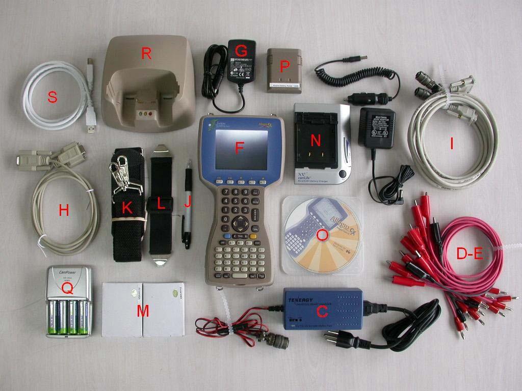
4 2 GRx8-32 accessories A 1x GRx8-32 IP receiver module B 1x Operation manual C 1x GRx8-32 IP receiver wall charger D 10x Red cable banana/alligator E 2x Black cable banana/alligator F 1x Allegro Cx field computer G 1x Allegro Cx wall charger H 1x Allegro Cx CE serial communication cable 9 pos. D-SUB female - 9 pos. D-SUB female I 2x Allegro Cx CE serial communication cable 9 pos. D-SUB female - 4 pos. Amphenol male J 1x Allegro Cx pen-style stylus K 1x Allegro Cx shoulder strap L 1x Allegro Cx hand strap M 2x Allegro Cx NIMH battery pack 3000mAh 3.6V N 1x Allegro Cx external NIMH 3000mAh 3.6V battery charger O 1x Allegro Cx utility CD P 1x Allegro Cx AA alkaline battery holder Q 1x Charger with 4 AA 2400mAh 1.2V NIMH batteries R 1x Allegro Cx USB power dock S 1x Allegro Cx USB cable for USB power dock 4
5 5

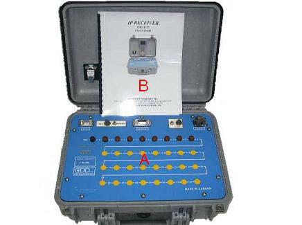
6 3 GRx8-32 components The GRx8-32 components are described in this section. A - RS-232 connector - 9 pin serial communication port This connector is used to connect the RS-232 cable between the Allegro Cx and the GRx8-32. B - CABLE/WIRELESS switch This switch is used to select CABLE (RS-232) or WIRELESS (Bluetooth) communication with the PDA. The red light indicates WIRELESS position. C - HARDWARE connector - 15 pin programmation port This connector is used to update the CPU and PLD software. 6
7 D - ON/OFF switch This switch is used to turn the GRx8-32 ON and OFF. The red light indicates ON position. E - CHARGER connector This connector is used to charge the 12V receiver s battery. F - REF terminal This terminal is the infinity electrode in pole configuration. In dipole configuration, this terminal is the first electrode in differential with the second electrode. G - NUMBERED terminals These terminals are referenced to the Ref terminal, infinity in pole configuration. In dipole configuration, the numbered terminals are differential terminals. 7

 and the GRx8-32 RS-232 connector (CABLE")
8 4 Quick start guide 1. Connect the electrodes into the terminals. 2. Turn ON the IP receiver using the ON/OFF switch on the GRx8-32 panel. 3. Select the communication mode using the CABLE/WIRELESS switch on the GRx8-32 panel. 4. Connect the RS-232 cable between the Allegro Cx (COM1) and the GRx8-32 RS-232 connector (CABLE communication only). 5. Turn ON the Allegro Cx with the On/Off key. 6. Double click on the GDD Rx icon. 8
9 7. Select the communication mode: RS-232 (CABLE) or BLUETOOTH (WIRELESS). 8. The following screen appears. 9. Click on the Start button to begin the acquisition procedure. 9
 the transmitter and receiver position. Click on the Ok button to continue.")
10 10. The following screen appears. Click on the Ok button to continue. 11. Enter the line informations, the first electrode position and the increment. Click on the Ok button to continue. 12. Enter or move (backward or forward) the transmitter and receiver position. Click on the Ok button to continue. 10


11 13. If the contacts are correct, click on the Next button to continue. *Note: If all stations show an INFINITE contact, the reference electrode might be disconnected. 14. Enter the transmitter current and click on the Confirm button to start the readings or use the tab and enter key. 15. The following screens appears. 11
 to stop the readings and save the")

12 16. Click on the Stop button or wait after the end of the acquisition (50 stacks) to stop the readings and save the data. 17. Click on the Yes button to confirm the operation. 18. Click on the Yes button to save readings into the memory. 12

13 19. Check the Redo positions option to change the transmitter or receiver position. Change the current value if it has changed and click on the Confirm button to save the current value If the Redo positions option is enable, enter the transmitter and receiver postion and click on the Ok button. *Each position can be change individually. 20. Repeat steps 9 through 19 to take another set of readings. 13


14 5. RS232/BLUETOOTH communication 1. Select the RS-232 communication mode to use the GRx8-32 with a serial communication cable. 2. Select the BLUETOOTH communication mode to use the GRx8-32 with a wireless connection. 2.1 The Bluetooth Device Search begin. 14


15 2.2 Select the Bluetooth device you want to use (the device name can be the GRx8-32 serial number or Brainboxes Adapter). 2.3 Select the Serial 01 Service Name and click on the Select button. 3. The following screen appears. 15
16 5 Tools menu Click on the Tools button to select one of the following options: Config Use the Config option to change: Eletrode array Active channel Trigger channel Line number and position Transmitter and receiver position Signal timing Mode Special Use the Special option to: Reinit the GRx8-32 Test the GRx8-32 with the internal simulator Graph Use the Graph option to display: Signal graph Noise monitor graph Cycle synchronization graph 16
17 Show Use the Show option to display: Windows chargeability SP (self potential) Decay curve Memory Use the Memory option to: Recall the previous memory Clear the memory Save the data in a file About Use the About option to display: GDD Rx software version 17
18 5.1 Config option Setup The Setup option is used to set the the electrode array, the active channel(s) and the trigger channel. 1. Select Tools Config Setup 2. The following screen appears. 3. Select the electrode array configuration: Dipole-Dipole Pole-Pole Pole-Dipole 18
. 5.")

19 4. Check the active channel(s). 5. Select the trigger channel, this channel is used for the synchronization process. 19


20 5.1.2 Position The Position option is used to set the line number and direction, the tansmitter and receiver position and the tansmitter and receiver increment. 1. Select Tools Config Position 2. The following screen appears. 3. Enter line number and select line direction. 20

21 4. Enter the transmitter and receiver first electrode position. 5. Enter the transmitter and receiver electrodes increment (deplacement between readings). 21


22 5.1.3 Windows The Windows option is used to set the signal timing and the mode. 1. Select Tools Config Windows 2. The following screen appears. 3. Select the signal timing. 22
: 240 Timin g (ms): 2000 80, 80, 80, 80, 80, 80, 80, 80, 80, 80, 80, 80, 80, 80, 80, 80, 80, 80, 80, 80 Semi logarithmic Windows: 20 Delay (ms): 40 Timing (ms): 2000")
23 4. Select the mode (windows time definition). Arithmetic Windows: 20 Delay (ms): 240 Timin g (ms): , 80, 80, 80, 80, 80, 80, 80, 80, 80, 80, 80, 80, 80, 80, 80, 80, 80, 80, 80 Semi logarithmic Windows: 20 Delay (ms): 40 Timing (ms): , 40, 40, 40, 40, 40, 80, 80, 80, 80, 80, 80, 80, 160, 160, 160, 160, 160, 160, 160 Logarithmic Cole Windows: 4 Delay (ms): 160 Timing (ms): , 220, 420, 820 Windows: 20 Delay (ms): 20 Timing (ms): , 30, 30, 30, 40, 40, 50, 60, 70, 80, 90, 100, 110, 120, 130, 140, 150, 160, 180,
: user defined Timing (ms): user defined If the User mode is selected, you have to enter the delay and the window(s) width.")
24 IPR-12 Windows: 11 Delay (ms): 50 Timing (ms): , 40, 40, 80, 80, 140, 140, 230, 230, 360, 360 User defined Windows: between 1 and 20 Delay (ms): user defined Timing (ms): user defined If the User mode is selected, you have to enter the delay and the window(s) width. 24


25 5.2 Special option Reinit The Reinit option is used to reset the GRx8-32 configurations and the communication with the Allegro Cx. 1. Select Tools Special Reinit 2. Click on the Yes button to reinit the GRx
26 5.2.2 Simulation *****For the next version of GRx8-32 (receiver box)***** 26
27 5.3 Graph option Signal The Signal option is used to display the signal graph of a selected channel. 1. Select Tools Graph Signal 2. The following screen appears. 27


28 3. Select the voltage and offset scale factor. 4. Select the time scale. 5. Select the display channel 28
29 Tools menu Auto Correction The Auto Correction option is used to optimized the graph scale and to correct the offset of the signal. This option should be used after one signal period (8 sec for a 2 sec time base). 1. Select Tools Auto Correction Restore The Restore option is used to reset the default setting. 1. Select Tools Auto Correction 29
30 PAUSE/GO The Pause/Go option is used to pause or play the signal. 1. Select Tools Pause or Tools Go 30

31 5.3.2 Noise The Noise option is used to display the noise graph of all channels. This option can be useful for troubleshooting if you have noise problem. *This option should be use before the transmitter is sending current. If the transmitter is sending current the Vp signal will be displayed for each active channel. 1. Select Tools Graph Noise 2. The following screen appears. Transmitter is not sending current Noise monitoring Transmitter is sending current VP monitoring 31

32 3. Select the voltage scale. 32
33 5.3.3 Cycle The Cycle option is used to show the channel synchronization. This option can be useful for troubleshooting if you have connection problem. 1. Select Tools Graph Cycle 2. The following screen appears. Red dots indicate that the GRx8-32 is not synchronized. Green dots indicate that the GRx8-32 is synchronized. If the GRx8-32 is synchronized and the green dots not moving at the same direction, check the electrodes position on the GRx8-32 front panel. 33


34 5.4 Show option Show Windows The Show Windows option is used to display the windows chargeability of each channel. 1. Select Tools Show Show Windows 2. The following screen appears. 34

35 5.4.2 Show Sp The Show Sp option is used to display the self potential (SP) in mv of each channel. 1. Select Tools Show Show SP 2. The following screen appears. 35

36 5.4.3 Decay Curve The Decay Curve option is used to display the decay graph of a selected channel. 1. Select Tools Show Decay Curve 2. The following screen appears. 3. Select the display channel. 36

37 5.5 Memory option Back Mem The Back Mem option is used to clear the last readings into the memory. 1. Select Tools Memory Back Mem 2. Click on the Yes button to clear the last readings. 37

38 5.5.2 Clear Mem The Clear Mem option is used to clear all the readings into the memory. 1. Select Tools Memory Clear Mem 2. Click on the Yes button to confirm the operation. 3. Enter 9999 in the text box. 38

39 4. Click on the Confirm button to clear all the readings into the memory. 5. A message will follow to confirm your operation. 39

40 5.5.3 Save File The Save File option is used to save the readings into a file. 1. Select Tools Memory Save File 2. Enter the file name. 3. Double click on the C_Drive folder. 40

41 4. Click on the OK button. 41

42 5.6 About option The About option is used to display the software version number. 1. Select Tools About 2. The following screen appears. 42


43 6 Data tranfer 6.1 ActiveSync installation and settings 1. To establish communication between the Allegro and a desktop PC, you need to install the ActiveSync software, which is included on the CD supplied by GDD. 2. Once ActiveSync is installed, a gray icon will appear in the bottom right corner of your desktop PC screen. 3. Right click on the ActiveSync icon to open the following menu and select Connection Settings Check Allow USB connection with this desktop computer. 43
44 6.2 Connect the Allegro Cx with a desktop PC 1. Turn ON the PDA 2. Insert the Allegro Cx in the USB power dock 3. The desktop ActiveSync icon is now green. 4. A small PCLink icon appears on the Allegro Cx taskbar. 44

45 6.3 Transfer file(s) from the Allegro Cx to a desktop PC 1. Double click on the My Computer icon on your desktop PC. 2. Double click on the Mobile Device icon. 45
")
46 3. Double click on the My Handheld PC icon. 4. Use the drag and drop or cut, copy paste functions to move file(s) on your desktop PC. 46


47 7 Bluetooth configuration 1. Turn On the GRx8-32 receiver. 2. Select the Wireless option with the Cable / Wireless switch. 3. Insert the Bluetooth reset key into the Hardware connector, wait 10 seconds AND REMOVED IT. 47


48 4. On the PDA, double click on the My Computer icon. 5. Double click on the C_Drive folder. 6. Double click on the GDD folder. 48

49 7. Double click on the BL-830 Config icon. 8. Click on the Yes button to confirm the operation. 9. On the taskbar, click on the BL-830 Config icon. 49


. 12.")
50 10. Click on the Bluetooth button to begin the Bluetooth Device Search. 11. Select the Bluetooth device you want to config (the device name can be the GRx8-32 serial number or Brainboxes Adapter). 12. The following screen appears. 50
 and click on the Reply")

51 13. Enter the Bluetooth Passkey (the Passkey is 1234) and click on the Reply button. 14. The following screen appears. 15. Click on the Yes button to confirm the operation. 51


52 16. Select the Remote Config option and click on the Select button. 17. On the taskbar, click on the BL-830 Config icon. 18. Select your module (Rx for Grx8-32 receiver) and click on the Config button. 52


53 19. Enter your GRx8-32 serial number and click on the Config button. 20. When the configuration is completed, the following screen appears. Click on the Ok button to close the window. 21. Click on the X button to close the window. 53


54 8 GDD Rx software update 1. Place the Allegro into the USB/Power Dock. The Allegro automatically turns on. 2. Double click on the My Computer icon on the desktop of your PC. 3. Double click on the Mobile Device icon. 54

55 4. Double click on the MyHandheld PC icon. 5. Double click on the C_Drive icon. 55

56 6. Double click on the GDD icon. 7. Rename the old version of the software to keep a backup on your Allegro Cx. Right click on the GDD Rx.exe icon and click on the Rename option. 56
57 Rename the software (example: GDD_Rx_Old Version.exe) 8. Use the drag and drop or the copy and paste functions to update the GDD Rx.exe software. 57


58 9 GRx8-32 CPU update 1. Insert the Bootloader key into the RS-232 connector. 2. Connect one end of the serial communication cable to the Bootloader key. 3. Connect the other end of the serial communication cable to the COM 1 or 2 port on your desktop PC. 58

59 4. Select the Cable option with the Cable / Wireless switch. 5. Turn On the GRx8-32 receiver. 6. Double click on the My Computer icon on the desktop of your PC. 59

60 7. Enter the serial port number and click on the Open Port button. 8. The following screen appears. 9. Click on the Open Hex button. 60
 and click on the Open button. 11.")

61 10. Select the new version of the CPU software (.hex file) and click on the Open button. 11. At the end of the transfer, the following screen appears. 12. Click on the Ok button to close the window. 61
62 10 Technical help If you encounter a problem not described in this manual, do not hesitate to contact Instrumentation GDD Inc. for help at: Tel.: (418) Fax: (418) Toll free line: gdd@gddinstrumentation.com Emergency out of business hours: Pierre Gaucher: Home phone: (418) Cell phone: (418) Régis Desbiens: Home phone: (418) Cell phone: (418) Any GDD IP Receiver that breaks down while under warranty or service will be replaced free of charge upon request for the duration of repairs, except for shipping charges. This service is subject to instrument availability but we have been able to honour this commitment up to now. Printed in Canada in April VER0-1F 62
SAMPLE CORE I.P. TESTER TDLV Instruction Manual
 SAMPLE CORE I.P. TESTER TDLV Instruction Manual 860 boul. de la Chaudière, suite 200 Québec (Qc), Canada, G1X 4B7 Tel.: +1 (418) 877-4249 Fax: +1 (418) 877-4054 E-Mail: gdd@gdd.ca Web site: www.gdd.ca
IP Post-Process Software
 IP Post-Process Software Version 1.2.4 Instruction Manual 860 boul. de la Chaudière, suite 200 Québec (QC), Canada, G1X 4B7 Tel.: +1 (418) 877-4249 Fax: +1 (418) 877-4054 E-Mail: gdd@gdd.ca Web site: www.gdd.ca
IP RECEIVER. New features GDD Rx program. Models GRx8-32 or GRx8mini. Version
 IP RECEIVER Models GRx8-32 or GRx8mini New features GDD Rx program Version 4.2.40 860 boul. de la Chaudière, suite 200 Québec (Qc), Canada, G1X 4B7 Tel.: +1 (41) 877-4249 Fax: +1 (418) 877-4054 E-Mail:
MPP PROBE. Instruction Manual. Model MPP-EM2S+
 MPP PROBE Model MPP-EM2S+ Instruction Manual 860 boul. de la Chaudière, suite 200 Québec (Qc), Canada, G1X 4B7 Tel.: +1 (418) 877-4249 Fax: +1 (418) 877-4054 E-Mail: gdd@gdd.ca Web site: www.gdd.ca Table
Allegro CX Field PC Release 1.07a
 Allegro CX Field PC Release 1.07a Installation Instructions June 2007 Enhancements Enhancements included in the Allegro CX Field PC operating system release 1.07a are as follows: Integration of the OS
SYSCAL Pro Standard & Switch ( ) Version
 Version") SYSCAL Pro Standard & Switch (48-72 - 96-120) Version 10 channels Resistivity-meter for Resistivity and IP measurements User s manual April 2006 IRIS INSTRUMENTS - 1, avenue Buffon, B.P. 6007-45060 Orléans
SYSCAL Pro Standard & Switch (48-72 - 96-120) Version 10 channels Resistivity-meter for Resistivity and IP measurements User s manual April 2006 IRIS INSTRUMENTS - 1, avenue Buffon, B.P. 6007-45060 Orléans
Operation Manual PFM Flex 2
 Operation Manual PFM Flex 2 The new and unique PFM FLEX Concept comprises 4 different Instruments for Flow and Pressure measurements. From the simplest Flex 1 to the most advanced Flex 4. The differences
MPP PROBE Model MPP-EM2S+ Instruction Manual
 MPP PROBE Model MPP-EM2S+ Instruction Manual 860 boul. de la Chaudière, suite 200 Québec (Qc), Canada, G1X 4B7 Tel.: +1 (418) 877-4249 Fax: +1 (418) 877-4054 E-Mail: gdd@gdd.ca Web site: www.gdd.ca Table
NX-588E USB Flash Programmer Instructions v1.1
 NX-588E USB Flash Programmer Instructions v1.1 Installing the NX-588E on a computer This process should take 5-10 min. 6. The following screen will appear: It is essential you carry out this step from
Installing LE History Record Reader program software.
 INSTALLATION & OPERATING INSTRUCTIONS FOR THE LE HISTORY RECORD READER These Instructions will inform you on how to install software to use the RS-232/USB Isolator- Adapter and your LE History Record Reader
CORD-XL Dual-Channel Electronic Chart Recorder User s Manual
 CORD-XL Dual-Channel Electronic Chart Recorder User s Manual Rohrback Cosasco Systems Inc. 11841 E. Smith Ave Santa Fe Springs, CA 90670 Tel: (562) 949-0123 Fax: (562) 949-3065 P/N 720701-Manual Rev E
SLUG DATA-LOGGER MANUAL. YieldPoint Inc. JULY 2009
 SLUG DATA-LOGGER MANUAL YieldPoint Inc. JULY 2009 Copyright 2009 by YieldPoint Inc. The Information contained herein is the exclusive property of YieldPoint Inc., except as otherwise indicated and shall
SYRDBT. SYRIS Handheld bluetooth RFID Reader
 SYRDBT SYRIS Handheld bluetooth RFID Reader V0200 SYRIS Technology Corp. Address: 12F., No.16, Sec. 2, Taiwan Blvd., West Dist., Taichung City 403, Taiwan TEL: +886-4-2207-8888 FAX: +886-4-2207-9999 E-Mail:
DS3 / DS31 User Manual
 DS3 / DS31 User Manual Please read the following warnings before using the product.. Contents of manual may differ based on the software version of products. Please visit web site(www.mobilebaseglobal.com)
LI Automated Soil CO 2 Flux System. Configuring the Palm Tungsten C for use with the LI-8100
 LI-8100 Automated Soil CO 2 Flux System Configuring the Palm Tungsten C for use with the LI-8100 NOTICE The information contained in this document is subject to change without notice. LI-COR MAKES NO WARRANTY
PITE 3926C Battery Data Logger User Manual
 PITE 3926C Battery Data Logger User Manual P-140922-V1.3 4/F, Bldg A, Chiwan Industrial Park, Shaodi Rd., Chiwan, Shekou Area, Shenzhen, China TEL: +86-755-2680 5759 FAX: +86-755-2688 0310 www.pitetech.com
USB Voltage and Current Tester Kit
 USB Voltage and Current Tester Kit Product ID: USBAUBSCHM This diagnostic kit gives you everything you need to make sure your USB devices are getting the proper charge. It enables you to: troubleshoot
OPERATING INSTRUCTIONS. ICE31 Version August, 2005
 OPERATING INSTRUCTIONS ICE31 DATA LOGGING SYSTEM FOR FIELD COMPUTER Allegro CX Field PC ICE31 Version 1.01 August, 2005 Geonics Limited 1745 Meyerside Drive, Mississauga, Ontario, Canada L5T 1C6 Tel: (905)
AI3100 Portable Reader User Manual
 AI3100 Portable Reader User Manual June 21, 2013 Copyright 2013 Softrail All rights reserved Softrail 1098 Venetia Road Eighty-Four, PA 15330 Tel. 888 872-4612 (toll free US and Canada only) Tel. 724 942-1473
OPERATING INSTRUCTIONS. EM38wm. Version 2.11 (Archer) EM38. Version 1.18 (Allegro CX) January, 2013
 EM38. Version 1.18 (Allegro CX) January, 2013") OPERATING INSTRUCTIONS EM38 DATA LOGGING SYSTEM FOR FIELD COMPUTERS ARCHER and ALLEGRO CX EM38wm Version 2.11 (Archer) EM38 Version 1.18 (Allegro CX) January, 2013 Geonics Limited 1745 Meyerside Drive,
OPERATING INSTRUCTIONS EM38 DATA LOGGING SYSTEM FOR FIELD COMPUTERS ARCHER and ALLEGRO CX EM38wm Version 2.11 (Archer) EM38 Version 1.18 (Allegro CX) January, 2013 Geonics Limited 1745 Meyerside Drive,
SPA Laptimer manual. The track side beacon beams infra-red across the track which is picked up by the small receiver connected to the laptimer.
 SPA Laptimer manual The new SPA Laptimer is an accurate and easy to use battery powered timing system, with a backlit graphic display with large easy to read digits. The track side beacon beams infra-red
BTH-1208LS Wireless Multifunction DAQ Device
 Wireless Multifunction DAQ Device Features Eight 11-bit single-ended (SE) or four 12-bit differential (DIFF) analog input channels Acquires data over Bluetooth or USB connection Maximum sampling rate of
STANDALONE INTERFACES USB-DMX 512 & 1024 CHANNELS V.1.1
 STANDALONE INTERFACES USB-DMX 512 & 1024 CHANNELS V.1.1 SUMMARY Hardware technical specifications... 3 Front Face of the 512 / 1024 channels interfaces... 4 Side Faces of the 512 / 1024 channels interfaces...
CyberComm Pro Data Acquisition Software Installation & User Guide
 CyberComm Pro 2.2.3 Data Acquisition Software Installation & User Guide ph 1100 and ph 2100 Bench ph and Bench ph/ion Meter Technology Made Easy... 68X090822 rev 1 Aug 2002 2 PREFACE Thank you for selecting
ASSAN ESC PC Interface Software User s Guide
 ASSAN ESC PC Interface Software User s Guide Dear customer, Welcome to use ASSAN ESC PC Connector and Interface Software. It allows of the Electronic Speed Controller programming in the desktop PC and
WIRELESS RF Implantable Stimulation User s Manual
 WIRELESS RF Implantable Stimulation User s Manual Triangle BioSystems International 2224 Page Rd. Suite 108 Durham, NC 27703 Phone: (919) 361-2663 Fax:(919) 544-3061 www.trianglebiosystems.com Table of
FRS / HM800 Update for Allegro MX
 Revision: May 1, 2012 Important notes and warnings These updates are for HM800 with Allegro MX only. FRS / HM800 Update for Allegro MX The process of updating FRS will erase all data associated with the
THREE-AXIS HALL MAGNETOMETER THM1176 TECHNICAL SPECIFICATIONS
 Measurement Ranges: Data Units: output: Sample rate: 100 mt, 500 mt, 3T, 20T ( automatic or manual ranging) - Bx, B y, B z (ASCII or binary, single point or array, calibrated or not) - Temperature (uncalibrated)
PowerTrac USB and Link Users Guide Software Installation & Operation Manual
 PowerTrac USB and Link Users Guide Software Installation & Operation Manual MAN-000038-00 REV A TABLE OF CONTENTS POWERTRAC USB USER... 1 POWERTRAC SOFTWARE INSTALLATION AND CONFIGURATION... 2 PREPARATIONS
Using the NEC MobilePro
 4 Using the NEC MobilePro Powering On and Off Making Display Panel Adjustments Enabling the Suspend Switch Using Application Shortcut Keys Recording Voice Memos Using PC Cards Using CompactFlash Cards
Phone: Fax: For calls outside the US please call:
 SM320 Phone: 1-800-757-3747 Fax: 1-800-676-0498 Email: dicksoncsr@dicksondata.com For calls outside the US please call: 1-630-543-3747 Display Temperature Data Logger Specifications Alarm Type: Audio/Visual
User Guide. Version 2.
 User Guide Version 2 www.rmepad.com RM epad TM User Guide Please read all instructions carefully before using Please retain these instructions for future reference RM epad TM contains replaceable, rechargeable
Technical Information
 Technical Information DATE: January 16, 2014 MODEL: RSP 1570, RSX 1550, RSX 1560 Main Software Upgrade Instructions The RSP-1570, RSX-1550 and RSX-1560 have three separate software modules main software,
Altus APS3G Quick Start guide
 Altus APS3G Quick Start guide Revision 1.0.1 Congratulations on purchasing your new Altus APS3G System. This Important Quick Start Guide contains information you need to set up and begin using your Altus
TriLink. User Guide. ISE, Inc. Second Edition October 2007 Fourier Systems
 ISE, Inc. 10100 Royalton Rd. Cleveland, OH 44133 Tel: (440) 237-3200 Fax: (440) 237-1744 http://iseinc.com TriLink User Guide Second Edition October 2007 Fourier Systems Contents Introduction...7 Chapter
HT660e Rugged Handheld Terminal
 HT660e Rugged Handheld Terminal - HT660e - Quick Reference Guide 400830G Version 1.0 HT660e Product Introduction & Accessory Kit HT660e Terminal Manual CD Communication Cable Battery Adaptor Kit Hand Strap
Compact yet Solid, SPP-R200
 Sales Manual BIXOLON Samsung Mobile Printer Compact yet Solid, SPP-R200 Product overview Compact yet Solid, SPP-R200 BIXOLON Samsung Mobile Printer SPP-R200, a small and lightweight mobile receipt printer
EM38MK2 Version 1.21
 OPERATING INSTRUCTIONS EM38-MK2 DATA LOGGING SYSTEM FOR FIELD COMPUTER Allegro CX Field PC EM38MK2 Version 1.21 December, 2008 Geonics Limited 1745 Meyerside Drive, Mississauga, Ontario, Canada L5T 1C6
APS-3 Revision Important Quick Start Guide. Typical Box Contents
 APS-3 Revision 3.0.0 Important Quick Start Guide Congratulations on purchasing your new APS-3 System. This Important Quick Start Guide contains information you need to set up and begin using your APS-3.
Hardware technical specifications Front Face of the 512 / 1024 channels interfaces LED 7-segments display operation:...
 SUMMARY Hardware technical specifications... 4 Front Face of the 512 / 1024 channels interfaces... 5 LED 7-segments display operation:... 5 LED 7-segments Sleep option:... 6 selection Mode button... 6
I. PANEL DESCRIPTION... 1
 Table of Contents I. PANEL DESCRIPTION... 1 II. OPERATING INSTRUCTION... 7 1. MA OUTPUT... 7 1A. GENERAL OPERATION 4-20MA... 7 1B. SELECT 0-20MA OR 0-24MA... 8 1C. ENTER A VALUE LESS THAN 1... 9 2. % (PERCENTAGE)
RESISTIVITY IMAGING:
 RESISTIVITY IMAGING: step-by-step operation of SYSCAL Switch resistivitymeters 1 st STEP: CREATE A SEQUENCE OF READINGS WITH ELECTRE II SOFTWARE 2 nd STEP: TAKE READINGS IN THE FIELD WITH SYSCAL SWITCH
Bluetooth Connection Kit
 Bluetooth Connection Kit Featuring the Socket Bluetooth Card and Windows CE software for adding Bluetooth wireless connectivity to the following mobile computers: Pocket PC 2000s Pocket PC 2002s Handheld
English. BELTPACK User Guide DE-DPS BELTPACK
 English BELTPACK User Guide DE-DPS BELTPACK Version 21/12/2017 CONTENTS 1 - DESCRIPTION OF THE SYSTEM 3 2 - OVERVIEW : 4 3 - BELTPACK DESCRIPTION 5 4 - HOW TO... 6 4-1...Switch ON the BELTPACK: 6 4-2...Unlock
IR-200F IrDA Mainboard Adapter
 IR-200F IrDA Mainboard Adapter The VScom IrDA Mainboard Adapter enables infrared wireless data communication by connecting the IrDA dongle to the built-in mainboard IR header connectors of your desktop
Operation Manual of Smart Battery Systems (SBS) with SmBus V1.1 support for 12.8V LiFePO4 battery pack (6.6Ah-100Ah)
 with SmBus V1.1 support for 12.8V LiFePO4 battery pack (6.6Ah-100Ah)") Operation Manual of Smart Battery Systems (SBS) with SmBus V1.1 support for 12.8V LiFePO4 battery pack (6.6Ah-100Ah) AA Portable Power Corp (http://www.batteryspace.com) Address: 860 S, 19 th St, Unit
Operation Manual of Smart Battery Systems (SBS) with SmBus V1.1 support for 12.8V LiFePO4 battery pack (6.6Ah-100Ah) AA Portable Power Corp (http://www.batteryspace.com) Address: 860 S, 19 th St, Unit
BDL-SERIES BATTERY DATA LOGGER
 BDL-SERIES BATTERY DATA LOGGER User Manual V1.1 1 Contents 1. Introduction... 3 1.1 Overview... 3 1.2 Technical Specification... 4 1.3 Composition... 5 2. DAC Wiring Connection... 5 2.1 Cell DAC Connection...
Emergency Dialer DIAL-ALERT MODEL: ED
 www.skylinkhome.com Emergency Dialer TM DIAL-ALERT MODEL: ED-100 101A083-002 FEB, 2006. CUSTOMER SERVICE 17 Sheard Avenue, Brampton, Ontario, Canada L6Y 1J3 Tel : (905) 456-8883 Fax : (905) 456-7819 Email
WiRobot TM DRK6000 QUICK START
 WiRobot TM DRK6000 QUICK START CAUTION: Before You Begin Please have the battery charged for 5 hours before usage. SYSTEM REQUIREMENTS: The PC requirements in using the WiRobot system are: PIII 550MHz
USB 3.0 Universal Dual Video Docking Station Installation Guide
 Introduction USB 3.0 Universal Dual Video Docking Station Installation Guide The USB 3.0 Universal Dual Video Docking Station is designed for a computer that has multiple connectivity demands. Features
Specification System... 5 Display Specification... 5 I/O Connectors... 5 Buttons and Indicators... 5
 ALGIZ 10X INDEX... 4 1. IDENTIFYING ALGIZ 10X... 5 Specification... 5 System... 5 Display Specification... 5 I/O Connectors... 5 Buttons and Indicators... 5 COM Port Assignment... 6 Boot Options... 6 Factory
User Manual. cmt-svr Startup Guide
 User Manual cmt-svr Startup Guide Table of Contents Chapter 1 Overview... 1 1.1 Specification... 1 1.2 Dimensions... 2 1.3 Connector pin designations... 3 1.4 USB host port and SD card slot... 3 1.5 Ethernet
CompactFlash/SDIO Connection Kit with Bluetooth Wireless Technology
 CompactFlash/SDIO Connection Kit with Bluetooth Wireless Technology Featuring a Socket CompactFlash/SDIO card and Windows CE software for adding Bluetooth capability to the following mobile computers:
BCT-200J Download Application (AC-65) Instruction Manual
 Instruction Manual") BCT-200J Download Application (AC-65) Instruction Manual Thank you for purchasing the AC-65 Data Download Application for your BCT- 200J Handheld Tester from Auto Meter Test Equipment. The AC-65 Data Download
BCT-200J Download Application (AC-65) Instruction Manual Thank you for purchasing the AC-65 Data Download Application for your BCT- 200J Handheld Tester from Auto Meter Test Equipment. The AC-65 Data Download
ELAN DIGITAL SYSTEMS LTD. CF428 COMPACT FLASH CF+ CARD USER S GUIDE
 ELAN DIGITAL SYSTEMS LTD. LITTLE PARK FARM ROAD, SEGENSWORTH WEST, FAREHAM, HANTS. PO15 5SJ. TEL: (44) (0)1489 579799 FAX: (44) (0)1489 577516 e-mail: support@pccard.co.uk website: http://www.pccard.co.uk
GV-IP Decoder Box Plus User s Manual
 GV-IP Decoder Box Plus User s Manual Before attempting to connect or operate this product, please read these instructions carefully and save this manual for future use. DBPV10-UM-A 2015 GeoVision, Inc.
DOWNLOAD KIT CYCLOCOMPUTER INTRODUCTION. Download unit & Download Software [e-train Data Ver.3] for Windows 98/ME/2000/XP
![DOWNLOAD KIT CYCLOCOMPUTER INTRODUCTION. Download unit & Download Software [e-train Data Ver.3] for Windows 98/ME/2000/XP](/thumbs/78/78392561.jpg "DOWNLOAD KIT CYCLOCOMPUTER INTRODUCTION. Download unit & Download Software [e-train Data Ver.3] for Windows 98/ME/2000/XP") CYCLOCOMPUTER Download unit & Download Software [e-train Data Ver.3] for Windows 98/ME/2000/XP 0365510 (ENG) 3 INTRODUCTION The CC-TR100 Download Kit contains the software e-train Data TM Ver. 3 and the
CYCLOCOMPUTER Download unit & Download Software [e-train Data Ver.3] for Windows 98/ME/2000/XP 0365510 (ENG) 3 INTRODUCTION The CC-TR100 Download Kit contains the software e-train Data TM Ver. 3 and the
Instruction It can display battery voltage, discharge current, time, battery
 Feature: Instruction NC, constant current battery discharge instrument It can display battery voltage, discharge current, time, battery capacity, power, total power, resistance Auto remember the last set
Bluetooth GPS Receiver. i-blue. User s Manual
 Bluetooth GPS Receiver i-blue User s Manual Published on 26-Oct-2005 8029407001A Table of Contents Chapter 1 Before you begin 3 1.1 Appearance 4 1.2 Checking the package content 4 Chapter 2 Getting started
EM31wm & ICEwm Version 2.08
 OPERATING INSTRUCTIONS EM31 and ICE DATA LOGGING SYSTEMS FOR FIELD COMPUTERS Archer and Allegro MX EM31wm & ICEwm Version 2.08 February, 2012 Geonics Limited 1745 Meyerside Drive, Mississauga, Ontario,
BATTERY TESTING SYSTEM
 BATTERY TESTING SYSTEM Operation Manual AA Portable Power Corp 860 South 19 th Street, Richmond, CA 94804, USA TEL: (510)525-3070 FAX: (510)525-4705 Website: Batteryspace.com email:sales@batteryspace.com
Handbook. CLIÉ handheld basic operations. Exchanging and updating files/data using the HotSync operation. Entering text on your CLIÉ.
 A-BU6-100-11 (1) CLIÉ handheld basic operations Exchanging and updating files/data using the HotSync operation Entering text on your CLIÉ handheld Customizing your CLIÉ handheld (Preferences) Exchanging
Optical CWDM Power Meter
 User Manual Optical CWDM Power Meter TheFibers Inc. A-1109 Keumkang Penterium IT Tower, 282 Hagui-ro, Dongan-gu, Anyang-City, Korea Tel: +82-31-381-6108 Fax: +82-31-381-6109 Email: sales@thefibers.com
The leg stand is located at the back of the product, on the top right. This adjustable-length leg stand will allow your ARCHOS to stand by itself on a
 About ARCHOS 9 PCtablet How do I activate the webcam? General It is activated by default and it automatically turns on when using an application that uses the webcam such as Skype. How can I install my
DPL4000 Portable Low Range Dew Point Analyzer
 OPERATIONS MANUAL DPL4000 Portable Low Range Dew Point Analyzer 7205 Edington Drive / Cincinnati, OH 45249 / Tel (513) 772-0060 / Fax (513) 772-9466 Page #1 of 16 M4581 DPL4000 Product Description: This
Getting to know MyPal
 E8 Getting to know MyPal Front features Back features Bluetooth LED Wi-Fi LED Power LCD touch screen Camera lens Camera flash Speaker Removable back cover ASUS Launcher button Calendar button Microphone
User Manual True Wireless Earbuds
 User Manual True Wireless Earbuds TWS109 Product Overview 1 Specifications 1 How to wear 1 Basic operation 2 LED indicator status of earbuds 2 Pair & connect 2 Charging 3 Reset / clear pairing history
Fast-charge your mobile devices
 10-Port USB 3.0 Hub with Charge and Sync Ports - 2 x 1.5A Ports StarTech ID: ST103008U2C This 10-port USB 3.0 hub enhances your system s capabilities by providing fast-charging for mobile devices, plus
NAV31. User s Manual GEOMAR SOFTWARE INC. Tel: Fax:
 TrackMaker NAV31 Version 1.34 for Windows CE.NET and Allegro CX Field Computer data acquisition & navigation software for the Geonics EM31 and GPS receiver User s Manual GEOMAR SOFTWARE INC. Tel: 905.306.9215
USR5500 Wireless Bluetooth Keyboard User Guide
 USR5500 Wireless Bluetooth Keyboard User Guide Package Contents - USRobotics Wireless Bluetooth Keyboard - User Manual Features - Bluetooth Version: Bluetooth V2.0 HID - QWERTY 78 key ANSI design, with
GosHawk II COMMUNICATIONS
 Version 4..10 GosHawk II COMMUNICATIONS Operating Instructions Introduction This program is a set-up and diagnostic utility for the Hawk SULTAN range of ultrasonic units. Hawk SULTAN units are designed
Trimble Recon Handheld: Using the Socket Bluetooth CompactFlash Card
 31 August 2006 Trimble Recon Handheld: Using the Socket Bluetooth CompactFlash Card This document explains how to use the Socket Bluetooth CompactFlash card on the Trimble Recon handheld running the Microsoft
Size: 84 x 118.4mm * 100P
 Size: 84 x 118.4mm * 100P *, ( ), ( ) *, According to the European WEEE directive, electrical and electronic equipment must not be disposed with consumers waste. Its components must be recycled or disposed
FLIER. User s Manual. ESC for Boat 2S to 22S FLIER
 FLIER User s Manual Tel:+86-0755-27905140 Business:sale@fliermodel.com Technic support:james@fliermodel.com Sales:Cathy@fliermodel.com/Lisa@fliermodel.com Skype:Fliermodel ESC for Boat Manual Thank you
Targus Wireless Web Card
 Targus Wireless Web Card TM Data-Capable Mobile Phone Wireless Web Card User s Guide 2 Chapter 1 - Introduction The World Is Your Network The Wireless Web Card (WWC) lets you connect your datacapable mobile
CncGcoder Models HD & HDx Manual
 CncGcoder Models HD & HDx Manual Table of Contents WELCOME... 3 IN THE BOX... 4 Optional Accessories...4 HANDHELD OVERVIEW... 5 Overview...5 Charging the Battery...6 Turning On and Off...6 Plugging in
Guide Specification for 3G Wireless Battery Monitoring System
 Guide Specification for 3G Wireless Battery Monitoring System 3/11A FirstLine Wireless BMS 1 1.0 Scope This specification defines the minimum requirements for a predictive FirstLine Wireless Battery Monitoring
FG-7000 Digital Force Gauge Operation Manual
 FG-7000 Digital Force Gauge Operation Manual Operators should wear protection such as a mask and gloves in case pieces or components break away from the unit under test. Whether the unit is ON or OFF,
SSW. Instruction Manual RS-PEN COMPUTER BM8
 SSW RS-PEN COMPUTER BM8 Instruction Manual 860 boul. de la Chaudière, suite 200 Québec (Qc), Canada, G1X 4B7 Tel.: +1 (418) 877-4249 Fax: +1 (418) 877-4054 E-Mail: gdd@gdd.ca Web site: www.gdd.ca Visit
The Pipe Reader. Please read this Instruction Manual
 THE PIPE READER The Pipe Reader Please read this Instruction Manual Contents Contents... 2 Quick start guide for the NLIS Pipe Reader... 4 Installation of software... 5 Standard Reader (USB Cable) Installation...
EziNav G3 User Manual
 EziNav G3 User Manual 4.3 Touchscreen GPS with Bluetooth About this User Manual Congratulations on your purchase of your Kogan EziNav G3 GPS. This user manual provides information regarding the various
Before Installing a PC software upgrade use Control Panel/Programs/Uninstall to uninstall the existing MULTiLOG2 software.
 Contents PC Software upgrade available here: (latest version is 2.19.153 dated 29-sep-2015)... 1 IMPORTANT Firmware revisions... 1 MULTiLOG2 battery specification... 2 Updated Windows drivers for the USB
DLT 300, DLR 360 Digi-Wave 300 Series Digital Transceiver and Receiver
 DIGITAL SPECIFICATION DATA Tour Guide Simultaneous Interpretation Portable Conference Wireless Intercom Team Teaching Hearing Assistance Personal Listening Portable Discussion Portable Presentation DLT
ARES II AUTOMATIC RESISTIVITY & IP SYSTEM
 ARES II AUTOMATIC RESISTIVITY & IP SYSTEM 850 W - 2000 V p-p - 5 A Transmitter for all Multi-Electrode and Manual Modes 10-channel Receiver with up to 20 Adjustable IP Windows 2D/3D Resistivity & IP Tomography
User Manual Bluetooth GPS Receiver
 User Manual 2944308 Bluetooth GPS Receiver 02944308 at a glance 1. Introduction The 02944308 is a GPS receiver with Bluetooth interface and built-in active antenna for high sensitivity to tracking signal.
High Accuracy Gloss Meter Operation Manual. This manual is only suitable for our single angle and multi-angles gloss meters.
 Content Introduction... 1 Cautions... 1 1. External structure description... 2 2. Switch on/off... 3 2.1 Startup... 3 2.2 Shutdown... 4 3. Basic operation... 4 3.1 Menu Operation... 4 3.2 Enter the main
10-Port USB 3.0 Hub with Charge and Sync Ports - 2 x 1.5A Ports
 10-Port USB 3.0 Hub with Charge and Sync Ports - 2 x 1.5A Ports Product ID: ST103008U2C This 10-port USB 3.0 hub enhances your system s capabilities by providing fast-charging for mobile devices, plus
3M Wireless Drive-Thru System Model G5 Technical Bulletin # 164
 3M Wireless Drive-Thru System Model G5 Technical Bulletin # 164 3M Wireless Communication System Model XT-1 Basestation Software Upgrade Overview: In the past you have conducted XT-1 Basestation software
Allegro CE OWNER'S MANUAL
 Allegro CE OWNER'S MANUAL Manual Part # 13076-04 Release Date: September 2003 Editor: Richard Timothy Page-ii Table of Contents Chapter 1 Introduction Welcome... 1-3 Allegro CE Overview... 1-4 Quick Start
7-Port Charging Station for USB Devices
 7-Port Charging Station for USB Devices Product ID: ST7CU35122 This USB charging station lets you set up an external, multiport dedicated station for charging tablets, smartphones and other mobile devices.
MANUAL PELITT MINI 1
 MANUAL PELITT MINI 1 TABLE OF CONTENTS 1. Warnings 3 2. Getting Started 3 3. Your Phone 4 4. File Manager 4 5. Phone book 4 6. Fun&Games 4 7. Call center 4 8. Messaging 4 9. Multimedia 5 10. Organizer
WRS-SST Series Wireless Sensing System Tools Technical Bulletin
 WRS-SST Series Wireless Sensing System Tools Technical Bulletin WRS-SST-100, WRS-SST-101 24-10139- 16, Rev. F Part No. 24-10139-16, Rev. F Issued March 2016 Refer to the QuickLIT Web site for the most
Intelligent DC UPS Module 12V/9~36V DC Input, 12V DC Output Uninterruptible Power Supply Module with Diagnostics
 Intelligent DC UPS Module 12V/9~36V DC Input, 12V DC Output Uninterruptible Power Supply Module with Diagnostics VESA or VESA mounting 9-36V input through terminal or power jack, or 12V through power jack
trimble r10 GNSS System
 TRIMBLE R10 SERIES RECEIVER QUICK START GUIDE trimble r10 GNSS System C Warning: For safety information, refer to the Safety Information section of the Trimble R10 GNSS Receiver User Guide. Five simple
DPM Bi-directional Digital DC Power Meter with built-in USB data logger & adapter External shunt model. User Manual
 DPM-3321 Bi-directional Digital DC Power Meter with built-in USB data logger & adapter External shunt model User Manual Bi-Directional DC Power Meter with built-in USB data logger & adapter. The new DPM-3321
Cadwell Easy Ambulatory Setup, Startup and Shutdown Guide
 Cadwell Easy Ambulatory Setup, Startup and Shutdown Guide This quick reference guide is intended to help with the installation and operation of your new Easy Ambulatory. More detailed operation instructions
Save and Restore Backups using itunes File Sharing
 Save and Restore Backups using itunes File Sharing Pictello (ipad, iphone and ipod touch). In this tutorial you will learn how to create, save and restore Pictello library backups with itunes File Sharing
BLUETOOTH RECEIVER (RX) FOR IPOD DOCKING SPEAKER
 FOR IPOD DOCKING SPEAKER") BLUETOOTH RECEIVER (RX) FOR IPOD DOCKING SPEAKER iskin CE-RX1000 USER GUIDE 1. Introduction Bluetooth wireless technology is a short-range communications technology intended to replace the cables connecting
BLUETOOTH RECEIVER (RX) FOR IPOD DOCKING SPEAKER iskin CE-RX1000 USER GUIDE 1. Introduction Bluetooth wireless technology is a short-range communications technology intended to replace the cables connecting
HIGH POWER STREET DANCE BOOMBOX
 HIGH POWER STREET DANCE BOOMBOX PBMSPG260L USER MANUAL Location of Controls 1. POWER SWITCH 2. DC IN JACK 3. USB PORT 4. AUX IN JACK 5. BATTERY INDICATOR 6. BLUETOOTH INDICATOR 7. GUITAR INPUT JACK 8.
BlueSoleil CE Software Manual. Contents. 3.1 System Requirements Installation Procedure Prepare to install...
 Contents 1 Introduction... 3 2 Features of BlueSoleil TM for WinCE 1.2.4... 4 2.1 Connection Management... 4 2.2 Device Management... 4 2.3 Configuration Management... 4 3 Installation BlueSoleilTM from