Amcrest IPM-HX1 1.3MP WiFi Hex Camera User Manual
|
|
|
- Darcy Heath
- 5 years ago
- Views:
Transcription

1 Amcrest IPM-HX1 1.3MP WiFi Hex Camera User Manual 1
2 Version Revised June 21st, 2017 Welcome... 6 Important Security Warning... 6 Important Safeguards and Warnings Features and Specifications Overview Features Device Overview Connection & Installation Connection Guide Installation Guide Camera Access Setup Default Username and Password Camera setup methods Setting up your camera for the first time Accessing your camera using multiple mobile devices
3 4.2.3 Configuring advanced settings on your camera Using Amcrest Cloud for remote viewing, storage, and playback Using plug-and-play for remote web access Amcrest View App Setup WiFi Configuration setup Ethernet WiFi Setup P2P Setup App walkthrough Motion detection setup Push notifications setup alerts setup Desktop access setup Amcrest IP Config Software method Installing the Amcrest browser plugin Logging in Amcrest Cloud Setup
4 4.6 Web Access Setup (AmcrestView.com) Installing the AmcrestView.com browser plugin User method Remote Web Access Setup UPnP/DDNS Remote Web Access Setup Port Forwarding Remote Web Access Setup NVR Access Operation and Interface Live Playback Setup Camera Configuration Video Audio Network
5 TCP/IP Connection PPPoE DDNS IP Filter SMTP ( ) UPnP SNMP Bonjour Multicast WiFi x QoS Event Video Detection Audio Detection
6 Alarm Abnormality Storage Schedule Destination Record Control System General Manage Users Restore Factory Settings Import/Export Auto Maintain Upgrade Information Version Log
7 Online Users Alarm Logout FAQs/Troubleshooting Glossary of Terms Appendix A: Toxic or Hazardous Materials or Elements

8 Welcome Thank you for purchasing an Amcrest Single Band Hex network camera! This user manual is designed to be a reference tool for the installation and operation of your IP camera. Here you can find information about the camera s features and functions, as well as information to aid in troubleshooting. Many of the setup and installation sections below have corresponding videos on YouTube To access the setup videos, please go to For access to the quick start guide and other support information, go to To contact Amcrest support, please do one of the following: Visit and use the form Call Amcrest Support using one of the following numbers Toll Free: (888) International Callers (Outside of US): USA: Canada: UK: Amcrest Customer Support support@amcrest.com Important Security Warning In order to keep your Amcrest camera secure and prevent unauthorized access, please make sure to follow the steps below: Always make sure that your camera has the latest firmware as listed on Never use the default password for your camera. Always ensure that your password is at least 8-10 characters long and contains a combination of lowercase characters, uppercase characters as well as numbers. 8
9 Important Safeguards and Warnings 1.Electrical Safety All installation and operation should conform to your local electrical safety codes. The product must be grounded to reduce the risk of electric shock. We assume no liability or responsibility for any fires or electrical shock caused by improper handling or installation. 2.Transportation Security Heavy stress, violent vibrations, and excess moisture should not occur during transportation, storage, and installation of the device. 3.Installation Handle the device with care. Do not apply power to the camera before completing installation. Do not place objects on top of the camera. 4.Repair Professionals All the examination and repair work should be done by qualified service engineers. We are not liable for any problems caused by unauthorized modifications or user-attempted repair. 5.Environment The camera should be kept in a cool, dry place away from direct sunlight, flammable materials, explosive substances, etc. This product should be transported, stored, and used only in the specified environments as stated above. Do not aim the camera at a strong light source, as it may cause overexposure of the picture, and may affect the longevity of the camera s sensors. Ensure that the camera is in a well ventilated area to prevent overheating. 6. Operation and Maintenance Do not touch the camera sensor or lens directly. To clean dust or dirt off of the lens, use an air blower or a microfiber cloth. 7. Accessories Be sure to use only the accessories recommended by manufacturer. Before installation, please open the package and check to ensure that all of the components are present. Contact the retailer that you purchased from, or Amcrest directly if anything is broken or missing in the package. 9
10 1 Features and Specifications 1.1 Overview The Amcrest Single Band Hex network camera is an excellent tool for digital surveillance that can be useful to a wide variety of users. The camera connects to any router, and uses an internet connection to allow the user to access all of its functionality from many internet connected devices. It s easy to use and can be set up in a relatively small amount of time. It has various functions such as recording, playback, and monitoring functionality and it synchronizes audio and video by default. This Single Band Hex network camera adopts a high-quality design in order to achieve high levels of reliability and security. It can be configured to work locally, as well as remotely over the internet. The Single Band Hex network camera also has a built-in WiFi adapter that allows for the camera to be used on a wireless network, without needing a physical connection to a router or PC. 1.2 Features The Amcrest Single Band Hex network camera has the following features: Network Access The Single Band Hex network camera connects to a wide variety of routers in order to connect to the internet, both through a wired connection and wirelessly. Once setup, the camera can be accessed remotely from a wide variety of internet connected devices, including PCs, iphones, ipads, Android tablets, and Android phones. Cloud Storage Functionality The Single Band Hex network camera is able to record video and audio streams to the Amcrest Cloud service in order to enable long-term storage for recordings. Amcrest Cloud also allows the user to easily find and download recorded video for playback from any internet connected PC or Mac computer. Advanced Playback Function This device supports real-time recording and supports searching through recorded footage, fast forward playback, and downloading of videos and screenshots. The Single Band Hex network camera can also playback in slow motion, backwards, and frame by frame as needed. When recording, the Single Band Hex network camera shows a date/time overlay to ensure accurate viewing of events when they occurred. Lastly, the Single Band Hex network camera can support video enlargement of certain zones within a stream. Advanced Network Protocol Support The Single Band Hex network camera is UPnP compatible, and also includes functionality for use with PPPoE, DDNS, and other protocols in order to allow remote and local connection with a large variety of network hardware. 10
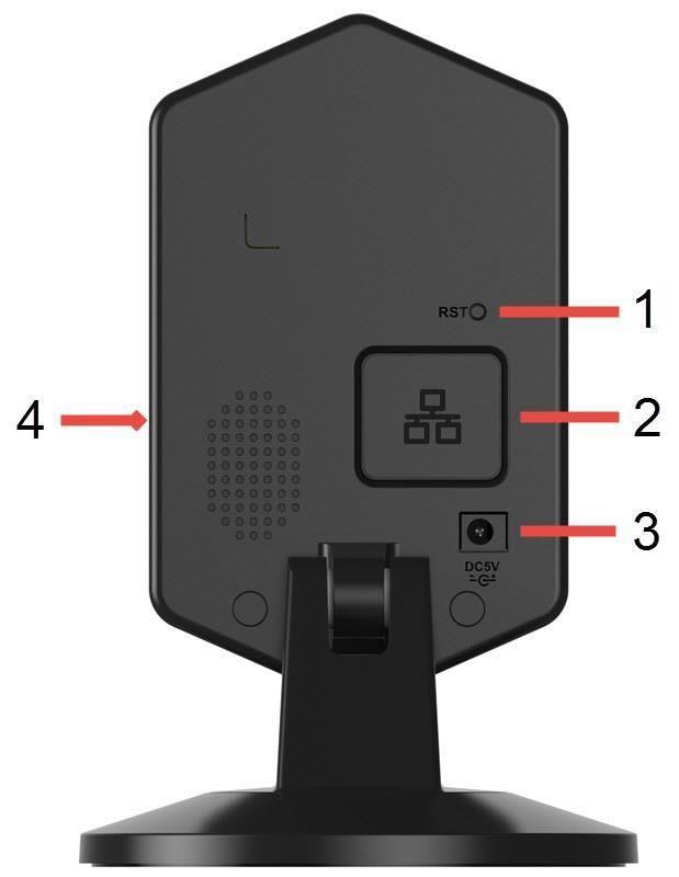
11 Note: There may be slight differences in functionality due to the existence of different product series. 2 Device Overview The diagram below shows the camera s profile and rear panel. 11
12 12
13 Please refer to the following chart for information about the camera and its ports. Port Number 1 Function Reset/WPS button/indicator light (For reset, press and hold for 10 seconds; for WPS, push once and release) 2 Network port 3 Power port 4 SD Card slot Please refer to the chart below for information about the camera s indicator light: Indicator Light Status Device Status Red Light is blinking quickly. Green Light is blinking. Red light is solid and steady. Green Light is solid and steady. Red Light is blinking slowly. The device is activating. The device is ready to connect or is connecting to the network. The device failed to connect to the network. The device is connected to the network and is functioning normally. The device is upgrading itself. The images below show the dimensions for the camera. The measurements are in millimeters (mm): 13


")
14 3 Connection & Installation This section provides information about the connection and installation of the Amcrest IPM-HX1 network camera. 3.1 Connection Guide The camera initially should be connected via the following method: In addition to connecting the camera to a computer, the camera should also be connected to a power source, by connecting the included power cable to both a power outlet, and the camera. 3.2 Installation Guide The camera has a standard camera tripod screw hole (1/4-20 UNC thread) for use in mounting the camera onto a stable surface. 14
15 Note: Prior to installation ensure that the installation environment can support at least 3 times the weight of the camera. 4 Camera Access Setup This section of the guide will provide the user with information on how to setup access to the camera through any of the following methods. 4.1 Default Username and Password To login to the system for the first time, use one of the following default username/password combinations. Once you ve successfully logged in, it is highly recommended to change the password for security reasons. Username: admin Password: admin Note: Logging in for the first time will prompt the user to change the password to the admin account. 15
16 4.2 Camera setup methods To make your experience with the Amcrest WiFi camera easy and simple, we've provided multiple ways to set up, view, and operate your camera depending on your needs. Please follow the instructions on this page to set up your camera in the way that works best for you Setting up your camera for the first time If setting up your camera for the first time, please follow the instructions as outlined in section Using the Amcrest View app on your smartphone or tablet, you can view your camera live from anywhere, and access features such as recording, taking snapshots, two-way audio, and more Accessing your camera using multiple mobile devices If you followed the app setup instructions in section to initially set up your camera and would like to add the camera to another smartphone or tablet, follow the instructions as outlined on section using your other devices Configuring advanced settings on your camera If you would like to configure your camera to enable advanced features such as motion detection, alerts, FTP, image adjustments, scheduling, and more, please follow the instructions as outlined on section 4.4 (Desktop access setup) Using Amcrest Cloud for remote viewing, storage, and playback Amcrest Cloud is our optional cloud storage and playback service which allows you to access recorded footage from any device. We offer 4 hours of free storage for your first camera. Please follow the instructions as outlined on section 4.5 (Amcrest Cloud setup) to sign up for our Amcrest Cloud service and get 4 hours of free storage Using plug-and-play for remote web access AmcrestView.com is a web portal that allows you to view your cameras and recordings quickly and easily from anywhere in the world using a web browser. Use AmcrestView.com if you need to simply check-in at a moment's notice. If you would like to use AmcrestView.com, please follow the instructions outlined on section 4.7 (Remote web access setup). 16
17 4.3 Amcrest View App Setup Amcrest IPM-HX1 cameras enable access through the use of the Amcrest View app on either ios or Android mobile operating systems. There are two versions of the app, Amcrest View Lite, and Amcrest View Pro. Amcrest View (Lite or Pro) on the App Store or Play Store. The Pro version contains features such as push notifications, sharing video and image files, exporting video in MP4 format, and exporting image files to your phone. The Amcrest Pro version of the app is now free to download from the Play Store and App Store. For purposes of this guide, we will use ios, though both apps have the same interface. The App Interface may differ slightly from the screenshots below as updates are released. Below, you'll find instructions on how to set up your camera, as well as instructions on how to configure different settings on your camera such as motion detection and alerts. Every major app setup method will be covered in the following sections WiFi Configuration setup Plug in your camera and follow the steps below to get your camera up and running. Please wait 30 seconds after plugging in the camera to allow it to initialize. The LED on the back will blink green when ready. 1. Download and open the Amcrest View Pro app from the App Store or Play Store. 17
18 Note: After installing the app, and before starting the app setup process, please make sure your phone is connected to the WiFi network you will be connecting your camera to. 2. From the home screen, tap the icon in the top-right corner to open the Device List. 18

19 3. Tap the Add Device button. 4. Tap WiFi Camera. Note: Move the camera or the phone to ensure that the entire QR code is visible and focused in the frame. In case the QR code cannot be scanned, please tap Enter S/N Manually to enter in the camera s serial number. 19
20 5. Tap WiFi Configuration Setup. 6. Scan the QR code from the sticker on your camera. Note: The default username is admin and the default password is admin. 7. Double check to ensure that your S/N (Serial Number) is entered correctly, then tap Next. 8. Give your camera a name, then enter in the camera s username and password. Once you ve filled out all of the fields, tap Next. 20

21 Note: Most Amcrest cameras can only connect to 2.4 GHz WiFi networks, so please ensure that your phone is connected to a compatible network. Otherwise, perform the Ethernet WiFi Setup method in section Enter your WiFi password, then tap Next. 10. Your camera is almost ready. Tap the Start Live Preview button to proceed with changing your password. 21
22 Note: Once the password is changed here, it will take effect immediately. If you forget your password, you can always hard reset the camera using the steps detailed in the FAQs section of this guide. 11. To ensure the security of your camera, you will be asked to change the password for your camera s default username (admin). Please select a password that is at least 8 characters long and one that uses a combination of uppercase letters, lowercase letters, and numbers. Then, tap Change Password. Note: To connect your camera to additional smartphones and tablets, please use the P2P Setup method as outlined on section Your camera is now ready to go! Tap the Start Live Preview button to get started! Still not working? If you have a dual band router, and your camera does not connect to your WiFi network after following the WiFi Configuration method below, please use the Ethernet WiFi Setup method as detailed in section Tip: To better understand the App's interface and features, please visit the Help Center within the app. To access the Help Center, tap the menu icon on the top left hand side, tap Help, then select which screen you'd like more information about. For additional assistance, please contact us at or give us a call at Step by step video tutorials available at 22
23 4.3.2 Ethernet WiFi Setup The Ethernet WiFi Setup process is a useful and stable setup method that uses a temporary Ethernet (hardwired) connection to your camera. By the end of the process, your camera will be working on WiFi and will not need a cable. If the WiFi Configuration setup method (see section WiFi Configuration setup) does not work, this is a great backup method. Alternatively, this method can also be used as an initial setup method, if preferred. It will take a few more steps but still ends with your camera being added to WiFi for wireless use. Plug in your camera and follow the steps below to get your camera up and running. Please wait 30 seconds after plugging in the camera to allow it to initialize. 1. Download and open the Amcrest View Pro app from the App Store or Play Store. 23
24 2. From the home screen, tap the icon in the topright corner to open the Device List. 3. Tap the Add Device button. 24


25 4. Tap WiFi Camera. 5. Tap Ethernet WiFi Setup. 25
26 6. Plug your camera into your router via an Ethernet cable. Don t worry, once the camera is set up, the camera can be unplugged and moved to a different location. Tap Next when finished. 7. Ensure your mobile phone is connected to the WiFi network that you will be connecting your camera to, then tap Next. Note: Move the camera or the phone to ensure that the entire QR code is visible and focused in the frame. In case the QR code cannot be scanned, please tap Enter S/N Manually to enter in the camera s serial number. 8. Scan the QR code [QR code icon] from the sticker on your camera. 9. Double check to ensure that your S/N (Serial Number) is entered correctly. Then, tap Next. 26

27 Note: The default username is admin and the default password is admin. 10. Give your camera a name, then enter in the camera s username and password. Once you ve filled out all of the fields, tap Next. 11. Pick a WiFi network, enter in the password, and tap Next. 27

28 Note: Note that once the password is changed here it will take effect immediately. If you forget your password, you can always hard reset the camera using the steps detailed in the FAQs section of this guide. 12. Your camera is almost ready. Tap the Start Live Preview button to proceed with changing your password. 13. To ensure the security of your camera, you will be asked to change the password for your camera s default username (admin). Please select a password that is at least 8 characters long and one that uses a combination of uppercase letters, lowercase letters, and numbers. 28

29 14. Your camera is now ready to go! Unplug the camera from Ethernet and power, then relocate the camera to anywhere within range of the WiFi network that you connected the camera to. Plug in the camera, then wait 1-2 minutes before tapping the Start Live Preview button P2P Setup The P2P Setup method is the method that should always be used to add a camera to more devices (smartphones, tablets, using the Amcrest View app) after the initial WiFi Configuration setup method has been followed and completed on the first device using the app. Alternatively, this method can also be used as a first, initial, setup method if preferred. However, please note that, if this is used as a first method, a hardwired (Ethernet) connection must be used and your camera will not be added to your WiFi network by the end of the app setup alone (like in the WiFi Configuration setup method). Instead, in this case, the camera must be added to WiFi separately, for instance, through desktop access (see section 4.4 Desktop access setup below). 1. This setup method should only be used if the camera is already connected to the Internet via WiFi or Ethernet cable. Use this setup method when you need to add the camera to additional mobile devices. Download the Amcrest View Pro app from the App Store or Play Store, then open the app. 29
30 2. From the home screen, tap the icon in the top right corner to open the Device List. 3. Tap the Add Device button. 30


31 4. Tap WiFi Camera. 5. Tap the Add Connected Device button near the top of the screen, then tap P2P Setup. Note: Move the camera or the phone to ensure that the entire QR code is visible and focused in the frame. In case the QR code cannot be scanned, please tap Enter S/N Manually to enter in the camera s serial number. 31

32 6. Scan the QR code from the sticker on your camera. 7. Double check to ensure that your S/N (Serial Number) is entered correctly, then tap Next. Note: The default username is admin and the default password is admin. 8. Give your camera a name, then enter in the camera s username and password. Once you ve filled out all of the fields, tap Next. 9. Your camera is now ready to go! Tap the Start Live Preview button to get started! 32

33 4.3.4 App walkthrough Once you've set up your camera, the app will present you with a popup that offers a walkthrough of different features. Tap Yes on this popup to begin a tour of all of the icons located on the Live View screen. In the future, you can always access the walkthrough again by opening the Menu, tapping Help, then tapping Wizard Motion detection setup Setting up motion detection for the Single Band Hex camera through the Amcrest View app will allow you to choose how your camera will react to and record motion. This is the best way to record events that are particularly of interest without needing to waste storage space by constantly recording. However, you can have motion detection set up along with 24/7 recording. The motion recordings will overlap the regular recordings and classify each motion-triggered recording as a motion event for your convenience when searching. There are a lot of customization options for motion detection that can be configured directly through the app. This gives you complete control over how to make motion detection work the way you want it to. Here is a list of all the advanced configuration options for motion detection: Schedule: Modify motion detection recording timings. Anti-Dither: Set how long motion detection can still be triggered after motion stops. Sensitivity: Select motion detection sensitivity. Region Setting: Specify motion detecting regions of the screen. Record: Toggle this switch to start recording when motion is detected. Delay: Set how long motion detection recording will continue after a motion event. Alarm Out: Configure alarm system integration. Snapshot: Toggle this switch to take snapshot when motion is detected. 33
34 Follow the steps below to setup motion detection on your camera. 1. From the home screen, tap the icon in the top left corner to open the main menu. 2. Tap Configuration Center to open the Configuration Center. 34

35 3. Tap Motion Detect to open the motion detection settings menu. 4. Select the camera that you want to modify motion detection settings for. 35
36 5. By default, motion detection is enabled. To configure advanced settings, tap the toggle switch in the Advanced Config row. 6. From this screen, you can modify the settings to fine tune how you use motion detection Push notifications setup Push notifications are an incredibly useful way to get instantly notified of motion events when you re on the go. This is a very convenient way to stay connected without having to constantly monitor your live feeds. It allows you to immediately tune into what s happening, when it s happening. There are several options for configuring exactly how you receive these notifications or alerts through your smartphone as well as options for what type of events trigger a notification. Note: This feature is only available on the Amcrest View Pro version of the app, which is free to download. Here is a list of the configuration options for push notifications: Push Type: Modify what type of push notifications are displayed. Motion Detect: Enable push notifications for motion detection alerts. Cam Masking: Enable push notifications for cam masking alerts. Local Alarm: Enable push notifications for local alarm alerts. HDD Alarm: Enable push notifications for low hard drive capacity alerts. 36
37 1. From the home screen, tap the icon in the top left corner to open the main menu. 2. Tap Push Notifications to open the Push Notifications settings menu. 37
38 3. Tap Configuration to open the push notifications settings menu. Tap Event List to see a history of past push notifications. 4. Select the camera that you want to modify push notification settings for. 38

39 5. Tap your camera s toggle switch to activate push notifications and configure settings. 6. From this screen, you can modify the settings to fine tune push notifications to your preference alerts setup The Amcrest Single Band Hex network camera has the ability to send you alerts to notify you when motion detection occurs. This is an alternative to using push notifications, which come directly through the Amcrest View app. Instead, alerts can come directly to your app and can also, of course, be checked on a computer. alerts can be a great way to keep an record of all your motion detection activity, instead of the app. However, keep in mind that alerts can be set up and used at the same time as having push notifications active. It is important to note that, even though you can use the same address as both the sender and receiver, it is highly recommended that you create a brand new (preferably a Gmail) account to use and configure for alerts. This will not mean that you have to use and log into two separate s, because you can forward all s from the dedicated alert account to your main account. The benefit of doing this is twofold. One, because setting up a new account means you can set up alerts without having to adjust or modify any of the security settings on your primary account and can work without a hitch. Two, because it will prevent your primary from being flooded by motion detection alert s. It is 39

40 highly recommended that you do not forward your new alert account to your primary account until you are satisfied with the sensitivity settings and frequency of motion alerts. 1. From the home screen, tap the icon in the top left corner to open the main menu. 2. Tap Configuration Center to open the Configuration Center. 40


41 3. Tap Alerts to open the alerts settings menu. 4. Select the camera that you want to modify alert settings for. Note: If your provider is not listed, select Other, then fill out the SMTP Server and Port fields. Note: You can specify, in seconds, the Interval: how long the camera should wait between sending s. 41
42 5. Start by selecting your provider. Continue by entering your address in the Username field, followed by the password to your in the Password field. Specify the sender in the Sender field, then scroll further down. 6. Enter a subject line under Subject, then add Recipients by entering in their addresses and tapping the plus sign. Tap the Test button to initiate an test. If successful, tap the Save button to save the settings. 4.4 Desktop access setup There are 2 ways to access your camera from a computer (laptop or desktop) which are: locally or remotely. Local Access: Logging into your camera s web interface from a computer or laptop device connected to the same network as your camera (home, office, etc.). Remote Access: Logging into your camera s web interface from a computer or laptop device connected to a network outside of your home or business network (coffee shop, work computer, etc.) Local access is preferred by those who, for security reasons or personal preference, do not wish to make their camera accessible from outside their network. However, there are several options available for remote access that use standardized and secure network protocols including SSL, TLS, DDNS, etc. Most other users require remote network access by way of their smartphones, tablets, laptops, or computers, for live viewing on the go. The following section will cover local access and remote access will be covered in section 4.7. It is important to configure and familiarize yourself with local access before attempting remote access. Keep in mind that any user can have both local and remote access simultaneously if they so choose. Before accessing your camera through a web browser, the following two steps must be completed: 1. You must access the camera s web interface with its IP address. 2. You must install the Amcrest web browser plugin. An IP address is just an identifier given to any devices that connect to a network. People use names, but internetconnected devices use a set of numbers called an IP address to talk to each other. Once you have the IP address, your computer will be able to find and communicate with your camera. A browser plugin is just like a translator. By using the camera on your computer through a web browser, you need to introduce a new piece of software that allows your computer to understand the language that the camera speaks in a way that a computer can understand. That s what the browser plugin is for. To access the camera s web interface, we will use the Amcrest IP Config Software method. 42

43 4.4.1 Amcrest IP Config Software method Amcrest IP Config Software can be installed for free onto your computer from Amcrest s official website. The IP Config Software is available for both Windows and Mac operating systems. To get directly to the downloads page, use this link: Otherwise, the steps below will walk you through how to download, install, and use Amcrest IP Config Software: 1. Log onto your computer, open your web browser of choice, and go to 2. Then, hover over the Support tab up top and choose Downloads from the dropdown. 3. This brings you to the downloads page. Click the IP Config Software download link on this page for either Windows or Mac. 4. Find the download in your Downloads folder, and click it to open the installer. 43


44 5. You will be asked to allow this program to make changes to your computer with a pop-up window, click Yes. 6. Once you see the first page of the installer wizard, click Next to continue. 7. On the next page, check the box next to I agree, then click Install. 44

45 8. After the progress bar completes, if you see a Windows Security Alert popup, click Allow access. 45
.")
46 9. This brings you to the main screen of Amcrest IP Config Software. Your camera will automatically be found on your network and appear in the list (if properly connected with an Ethernet cable to your router). You will also see the IP address associated with your camera. The e icon to the right allows you to launch directly into your web browser from this screen. Note: This e icon will automatically take your camera s IP address and use your computer s default web browser to access and log into your camera. If your default browser is not Internet Explorer, you can write down the IP address from the Amcrest IP Config Software (IP address located above), open up Internet Explorer yourself, 46

47 and type that into the search bar to get to the login screen. Typing your IP address directly into the search bar will look something like this: Installing the Amcrest browser plugin Once you ve followed one of the above methods to get to the login screen for the camera, follow the below steps to install the browser plugin on Internet Explorer: 1. On the main login screen, you should see a popup in the center. Click Install. 2. An install button will appear on the bottom of the screen for the plugin: webplugin.exe. Click Run, then go through the prompts of the install wizard. 3. Once you see the notification along the bottom row. Click the small arrow to the right of the Allow button, and select Allow for all websites. 4. If you see a popup window asking you to allow the plugin, mark the checkbox next to Do not show me the warning for this program again, then click Allow. 47
 2.")
48 4.4.3 Logging in Before attempting to gain local access, you will need to make sure the following items are true: 1. You have your login credentials (if using this local access method as your first, initial choice to setup your camera, only items 2 and 3 of this list need to be true) 2. You have located your camera s IP address 3. You have installed the Amcrest browser plugin If you did not follow any of the app setup methods covered in section 4.3, and this is your first time logging into your camera, please use the following default username and password: Username: admin Password: admin Note: After logging in for the first time, you will be prompted to change your password. To find the camera s IP address, please refer to the Amcrest IP Config Software method (section 4.4.1) above. To install the browser plugin for the camera s web interface, please refer to the section above. 1. Take the IP address and type it into the Internet Explorer search bar, then hit Enter. It should look something like 48
, navigate to Setup > Network > WiFi, then double-click the line that shows your WiFi network.")
49 2. Enter your login credentials. You may be prompted to change your password. 3. (Optional) Save this web page as a Favorite for easy access in the future. The camera is now successfully set up for live viewing and playback! To setup WiFi (optional), navigate to Setup > Network > WiFi, then double-click the line that shows your WiFi network. If necessary, enter your WiFi network's password. The camera may take up to 2 minutes to connect to the WiFi network. Click the Refresh button after the process is complete. Once the camera has successfully connected to your WiFi, you should see the word "Connected" in green display next to your WiFi network's name in the WiFi Network information table under the WiFi List table. Note that the IP address may have changed once connected to WiFi. Be sure to use the IP Config tool to access the camera using its updated IP address. After configuring the camera to connect to WiFI, use the P2P Setup method on section to connect the camera via your smartphone or your tablet. For quick and easy remote access on your PC or Mac, please use AmcrestCloud.com (section 4.5) or AmcrestView.com (section 4.6). To setup advanced remote access via UPnP/DDNS or Port Forwarding see section
50 If you are still having trouble and would like to watch a video on how to setup the Single Band Hex camera for local access on a computer/laptop, go to click the Videos tab, then watch the video titled Desktop/Laptop Access Setup for ProHD & HDseries WiFi Cameras. For additional assistance, please contact us at or give us a call at Amcrest Cloud Setup The Amcrest IPM-HX1 cameras are able to sync with Amcrest Cloud; a service that stores recorded video streams in order to enable long-term storage. Amcrest Cloud also allows the user to easily find and download recorded video for playback from any internet connected PC or Mac computer. 1. Connect the camera to a power supply using the included power adapter. 2. Connect the camera to the internet, either through a wired connection (see section 3.1), or through WiFi (see section 4.2) 3. Using a web browser on your PC or Mac, visit and register for a free account. Once registered, click the Add Camera button. Select Amcrest, give the camera a name, and enter the camera s SN (located on the bottom of the camera), then click Next. 4. On the settings page, you can adjust optional preferences for your camera. Once settings have been adjusted, click Finish. Your camera is now successfully set up for cloud access and storage. 5. View your camera live or watch recorded clips using the menu button on the top of the page. You can also use the Amcrest Cloud app on ios and Android to add more cameras, play recordings, and view your camera live, from anywhere. 6. For additional assistance, please contact us at or give us a call at Step by step video tutorials available at Web Access Setup (AmcrestView.com) You can access your camera through a computer using the P2P web portal AmcrestView.com for quick plugandplay access. It uses the same technology as the Amcrest View mobile app and is an easy, non-technical setup method. There are 2 methods of accessing your camera using AmcrestView.com: the user method (registering an account for login), and the device method (instant direct access using the serial number). Both of these methods require that the Amcrest browser plugin be installed for AmcrestView.com. 50

51 4.6.1 Installing the AmcrestView.com browser plugin 1. Open Internet Explorer, type into the search bar, and hit Enter. This will take you to the login screen: 2. Once you re on the login page, you will see a message about installing the plugin below the login box. Click Download Now: 3. This will take you to another page where you will need to click the Download Now button: 4. You will be prompted by the browser to install the plugin. Click Run: 51


52 5. You may be prompted to verify this download. This software is not harmful to your computer and will not make any unwanted changes. To verify, start by clicking View Downloads: 6. In the View Downloads page, right click the plugin, then click Run Anyway. 7. The plugin will close your browser sessions to install. Save any pages, then click Yes: 52

53 8. On the next prompt, it will say the install was successful and ask you to restart your browser. Click OK: 9. You will be taken back to the login page and see another notification from your browser asking you to allow this plugin on this web page. Click the small arrow next to Allow, then click Allow for all websites: 10. Another popup will appear asking you to allow this plugin. Mark the checkbox next to Do not show me the warning for this program again, then click Allow: Now the plugin has been installed successfully and you can continue on to register for an account for camera access through AmcrestView.com 53

54 4.6.2 User method The user method requires that you first install the Amcrest browser plugin for AmcrestView.com. Then, you can register for an account to set up your camera. 1. On the main login screen, click the Register Now button: 2. You will be taken to the registration form. Enter your Username, Password, then Confirm Password, type your , enter the Verification Code, make sure the box is checked confirming you ve read the Amcrest Terms of Service, then click Create an Account: 54

55 3. You will see the Registration Successful message and a confirmation will be sent to you: Check your , and click the confirmation from AmcrestView.com: 55

56 4. Once you ve opened the , click the confirmation link inside to complete your registration: 5. You will be taken back to AmcrestView.com and shown confirmation that your account has been activated. Click Go to Login: 6. You will be taken back to the login screen. Enter your new AmcrestView.com username and password, then click Login: 56


57 7. A popup will appear from your Windows Firewall. Click Allow access: 8. You will be taken to the main screen of your account. From here, click the Add Device button: 57
 this can be found on the sticker attached to the bottom of your camera or through the")

58 9. Now you can enter your camera s information. Enter a Device Name (this can be anything). Then, fill in the S/N (serial number) this can be found on the sticker attached to the bottom of your camera or through the web interface (click the i icon in the top bar, then click Version). Enter your username and password for the camera, not the username and password you just created for AmcrestView.com. To find your camera login credentials, please refer to section Finally, click OK: 58
59 10. You will then see your camera added to the device list on the main screen. Click the eye icon to view the live feed: 11. Your browser will give you a notification asking you to allow popups from AmcrestView.com. Click Options for this site, then click Always allow: 12. You will be taken to the live view page and given a notification to allow the plugin to pull the video feed through here. Click the small arrow to the right of Allow, then click Allow for all websites: 59

60 13. A final popup will appear asking you to confirm that you allow this plugin on your browser. Mark the checkbox next to Do not show me the warning for this program again, then click Allow: Now you can enable any of your added cameras to see their live feeds. In the top-right panel, there is a channel list. Click the small square icon to enable your feed for an added camera to see the video feed: 60
, click the M and change it to an S again. 4.")
61 Click the S to change it to an M which stands for Main Stream and will give you a full HD quality video stream. To go back to Sub Stream, for lower quality video (that works better on slower internet connections), click the M and change it to an S again. 4.7 Remote Web Access Setup There are two main methods for setting up remote access: UPnP/DDNS, and Port Forwarding UPnP/DDNS Remote Web Access Setup Using Universal Plug and Play (UPnP) and Dynamic Domain Name Server (DDNS) functionality is the easiest way to setup stable remote access. For this method, your router should support the UPnP networking protocol and the protocol should be enabled. Please refer to your router manufacturer s documentation to learn how to enable UPnP on your router. Below is a step-by-step walkthrough that details how to setup the Amcrest IPM-HX1 Cameras for Remote Web Access using UPnP and DDNS: 1. Login to your camera s web interface, open the main menu then go to Setup -> Network. 2. Using the left hand menu, go to the Connection menu, and write down the HTTP port. It is recommended to ensure the port number is at least 5 digits long to prevent any port conflicts. If need be, change the port to a 5 digit number that is less than 65535, note the number down, and click save before proceeding to the next step. 61
62 3. The system will prompt you to reset the camera. Click OK and wait for the camera to restart. 4. Restarting the camera may cause the device to use another IP address. Use the included IP Config tool to find the IP address as detailed in section Login to your camera, open the main menu then go to Setup -> Network. 6. Click the Connections menu item on the left hand menu, and ensure that the HTTP port has changed. 7. Click the DDNS menu item on the left hand menu, pick Amcrest DDNS from the drop down box, click the checkbox next to Server Type, and then click the Save button on the bottom right. 8. To set a custom DDNS name, fill out the Domain Name field and click Save. 9. Write down the entire Domain Name field, including the white text that says.amcrestddns.com 10. Click the UPnP menu item on the left hand menu, and click the enable checkbox at the top. 11. While in the UPnP menu, double click the HTTP port, and change both the internal and external HTTP ports to match the number that was used in step Uncheck the last 4 checkboxes in the PAT table on the UPnP menu. 13. Click apply, then exit this menu to go back to the main menu, then re-enter the UPnP menu, and ensure the UPnP status says Mapping Successful. 14. Open a web browser and enter in the DDNS domain name address from step 9, enter in a colon, then type the port number from step 4 on to the end. a. For example, if the DDNS domain name is and your HTTP Port is 33333, the URL would be The browser may prompt you to install a plugin. Click install to download the plugin, and then click on the plugin installation file to install the plugin. 16. If the browser prompts you to allow the plugin to work on the computer, hit Allow to ensure the plugin can run successfully. 17. Enter in login details into the username and password fields and click login. If the process above is not working, please contact Amcrest Support via one of the following options: Visit and use the form Call Amcrest Support using one of the following numbers Toll Free: (888) International Callers (Outside of US): USA: (888) Canada: UK: Amcrest Customer Support support@amcrest.com Port Forwarding Remote Web Access Setup Port Forwarding is an alternative method to setting up remote access for the Amcrest IPM-HX1 Cameras. This method should only be used if the UPnP/DDNS Remote Access method did not work. Below is a step-by-step walkthrough that details how to setup the camera for Remote Web Access using Port Forwarding: 62
63 1. Login to your camera, open the main menu then go to Setup -> Network. 2. Open the TCP/IP settings screen. 3. By default, the camera has the mode set to DHCP. Ensure that DHCP is selected. The IP Address, Subnet Mask, Default Gateway, Preferred DNS, and Alternate DNS should all be 0s if DHCP is selected. 4. Click Save to save these settings. This should now open the main menu. 5. From the main menu, go to Setup -> Network. 6. On the TCP/IP settings screen, the IP Address, Subnet Mask, Default Gateway, Preferred DNS, and Alternate DNS should all be populated. 7. Click the radio button next to Static, to change the mode to Static. 8. Write down the IP Address that is currently in the IP address field. 9. Click the Save button. 10. Using the left hand menu, go to the Connection menu, and write down the TCP, UDP, and HTTP port number. It is recommended to ensure that these port numbers are at least 5 digits long to prevent any port conflicts. If need be, change each of these port numbers to a 5 digit number that is less than 65535, note the numbers down, and click save before proceeding to the next step. 11. Go to and check to ensure each of the port numbers specified in step 10 is open. 12. Write down the manufacturer name, brand, and model name for the router that the camera is connected to, and then proceed to on your web browser. 13. Open the port forwarding guide section on the left hand side menu. 14. Find the router brand name in the list, and click it. 15. Find the router model number, and click it. 16. Click the Default Guide link near the middle of the page. 17. This guide will help you take the step necessary to port forward on the router. Follow these steps, and then return to the camera. 18. Login to your camera, open the main menu then go to Setup -> Network. 19. Click the DDNS menu item on the left hand menu, pick Amcrest DDNS from the drop down box, click the checkbox next to Server Type, and then click the Save button on the bottom right. 20. To set a custom DDNS name, fill out the Domain Name field and click Save. 21. Write down the entire Domain Name field, including the white text that says.amcrestddns.com 22. Open a web browser and enter in the DDNS domain name address from step 21, enter in a colon, then type the HTTP port number from step 10 on to the end. a. For example, if the DDNS domain name is and your HTTP Port is 33333, the URL would be Enter in login details into the username and password fields and click login. If the process above is not working, please contact Amcrest Support via one of the following options: Visit and use the form Call Amcrest Support using one of the following numbers Toll Free: (888) International Callers (Outside of US): USA: (888) Canada: UK: Amcrest Customer Support support@amcrest.com 63
64 4.8 NVR Access The camera supports connecting to any NVR that uses the ONVIF standard. This allows the camera to view live playback and to save recorded data to a network storage device. To connect to an NVR, use an Ethernet cable to link the camera to the NVR. 64

65 5 Operation and Interface This section of the manual details the camera s interface, as well as all of the operations the camera can perform. The main interface of the camera contains 6 major tabs on the top of the screen. By default, the interface opens on the Live tab. 5.1 Live The Live tab allows the user to see a live video feed from the camera. The live tab has 4 main sections: 65
66 Section 1: This bar allows the user to select which stream type and which protocol they want to choose. For more information on stream types, see section For more information on protocols, see section Section 2: The functions bar allows the user to perform different camera functions while in live mode. See the table below for an explanation of the different functions available: Button Function Name Function Description Alarm Output Click this button to generate an alarm output signal. This button becomes red/grey depending on alarm output activation or cancellation. Digital Zoom Click this button to activate the zone selection function. This allows the user to use the mouse to select a zone to zoom in on. Snapshot Triple Snapshot Manual Record Audio Bidirectional Talk Click this button to take a screenshot of the live feed. The picture is saved at the path specified in Setup -> Camera -> Video -> Path. Click this button to take 1 screenshot per second for 3 seconds. The pictures are saved at the path specified in Setup -> Camera -> Video -> Path. Click this button to manually record video. The video is saved at the path specified in Setup -> Camera -> Video -> Path. Click this button to enable or disable audio output from the camera. This feature allows the user to listen in on the audio the camera s microphone is picking up. Click and hold this button to enable bidirectional talk. This feature allows the user to broadcast audio from their computer to the camera. While this is active, the camera s speaker is shut off in order to keep audio quality high. 66
67 Help Click this button to open a window that details the buttons and functions shown on this screen. Section 3: This bar allows the user to change video settings for the live playback screen. See the below table for an explanation of the video settings: Button Function Name Function Description Image Adjustment This button opens the image adjustment toolbar, which allows the user to adjust brightness, contrast, saturation, and hue for the live feed s picture. Adapt/Original Size This button allows the user to switch between displaying the original size of the stream in its set resolution, or to adapt to the size of the monitor display the feed is being viewed on. Full Screen This button allows the user to make the live feed go into full screen mode. Double click the mouse or click the ESC button to exit full screen mode. Width/Height Ratio This button allows the user to change the width/height ratio for the live feed. The options are Original and Adaptive. Original uses the aspect ratio of the stream s set resolution, and adaptive fits the feed to the aspect ratio of the monitor display the feed is being viewed on. Stream Fluency This button allows the user to change the stream fluency. There are 3 options. Realtime reduces delay and decreases fluency, and Fluency has a larger delay but the video stream becomes more fluid. Section 4: This section of the Live tab shows the picture that the camera is broadcasting. The bitrate is shown in the top left corner, the native resolution is shown in the top right corner, the time stamp is shown below the native resolution, and the camera type is shown in the bottom left corner. 5.2 Playback The Playback tab allows the user to playback the camera s recorded video. Below is a screenshot of the Playback tab: 67

68 This is the interface for the playback menu. There are 7 main sections: 1. Quick Actions: This panel allows the user to zoom in on playback footage, take a snapshot of the playback footage, or open the help menu. 2. File Menu: This panel allows the user to select a file type and data source. 3. Calendar: This panel allows the user to pick a date that they would like to playback video from. When a date has recorded footage available, it s green. The current date is blue, unless it has recorded footage, then it s a lighter green. 4. File List: This button opens a file list of all recorded video for a specific date range. From here, the user can download these videos to their PC. 5. Trim Panel: This panel allows the user to trim playback video for download. By specifying time stamps, the user can trim down. 6. Recorded Video Panel: This panel allows the user to specify what type of video they would like to playback and it also allows the user to select where to start playback from. The buttons on the bottom right allow the user to select a zoom level. 7. Playback Bar: This panel allows the user to control playback. It also allows the user to control playback speed, and playback volume. Clicking the File List opens the following screen on the sidebar: This allows the user to select files for download. Select the files by clicking the checkbox next to each file, and then click to download the files to the PC. 68

69 5.3 Setup The Setup tab allows the user to change different camera settings. Below is a screenshot of the setup tab: 69

70 There are 3 main sections to note in the Setup tab: 1. Menu Bar: The menu bar is composed of menu sections, which when clicked display any menu items that fall under their category. 2. Menu Items: These menu items each open up a different menu that allows the user to change specific settings for the camera. 3. Menu Tab: These tabs open up menu options for certain menu items. Note: To view additional information about any of the information in the menu, click the the top right corner. button near In the rest of section 5.3, we will be exploring all of the different menus that are available through web access Camera This menu section allows the user to change different camera settings for video, audio, and to manage image profiles Configuration This menu allows the user to configure image profiles for normal, day, and night usage. 70

71 Configuration Below is a screenshot that shows the Configuration tab in the Configuration menu item: Below is an explanation for each of the fields on the Configuration tab in the Configuration menu item: Profile: This dropdown box allows the user to select which profile to modify. The 3 options are Day, Night, and Normal. Brightness: This slider is used to adjust playback and recorded video window brightness. The value ranges from 0 to 100. The default value is 50. The larger the number, the brighter the video is. When you input the value here, the bright section and the dark section of the video will be adjusted accordingly. You can use this function when the whole video is too dark or too bright. Please note the video may become hazy if the value is too high. The recommended value ranges from 40 to 60. Contrast: This slider is used to adjust playback and recorded video window contrast. The value ranges from 0 to 100. The default value is 50. The larger the number is, the higher the contrast is. You can use this function when the whole video brightness is OK but the contrast is not correct. Please note the video may become hazy if the value is too low. If this value is too high, the dark section may lack brightness while the bright section may over expose. The recommended value ranges from 40 to 60. Saturation: This slider is used to adjust playback and recorded video window saturation. The value ranges from 0 to 100. The default value is 50. The larger the number, the stronger the color is. This value has no effect on the general brightness of the whole video. The video color may become too strong if the value is too high. For the grey part of the video, distortion may occur if the white balance is not accurate. Please note the video may not be clear if the value is too low. The recommended value ranges from 40 to
72 Sharpness: This slider is used to adjust the sharpness of the video. The value ranges from 0 to 100. The larger the value is, the clearer the edges are and vice versa. Note: The higher the value, the higher likelihood of picture noise occurring. The default value is 50 and the recommended value ranges from 40 to 60. Gamma: This slider is used to adjust the gamma of the video. The larger the number, the brighter the video is. The default value is 50 and the recommended value ranges from 40 to 60. Anti-Flicker: These radio buttons allow the user to select what type of anti-flicker technology should be used for the video feed. The three options are 50 Hz, 60 Hz, and Outdoor. The desired option should offset any flickering effect caused by the electrical current used in the specific area. Exposure: This dropdown box allows the user to select the exposure type for the video feed. The options are Auto, Low Noise, Low Motion Blur, and Manual. When low noise is selected, an additional option to specify a gain range appears below this box. When low motion blur is selected, an additional option to specify shutter speed appears below this box. When manual is selected, additional options to specify a shutter speed and a gain range appear below this box. White Balance: This dropdown box allows the user to select the white balance for the video feed. The different options are Auto, Sunny, Night, Outdoor, and Customized. Selecting customized opens a menu that allows the user to set specific red or blue values. Day & Night: This dropdown box allows the user to select which type of picture is displayed. The options are Color, Auto, and Black & White. D&N Sensitivity: This option allows the user to change the Day/Night Sensitivity of the camera. The three options are Low, Middle, and High. The higher the sensitivity, the quicker the camera will change into another mode depending on the light levels. D&N Delay: This dropdown box allows the user to set a delay in seconds for how long it takes to switch between Day and Night modes. The values range from 2 seconds to 10 seconds. BLC Mode: This dropdown box allows the user to select Back Light Compensation. The values are Off, BLC (Auto), WDR, and HLC. This feature should only be used in black lit environments. Indicator Light: This dropdown box allows the user to select whether the indicator light on the back of the camera is on or off for the selected profile. Mirror: This radio button allows the user to turn the mirroring feature on or off. Turning mirroring on will mirror the picture. Flip: This dropdown box allows the user to flip the video feed picture. Flipping the picture is recommended only if the camera is mounted upside down. 3D NR: This radio button allows the user to turn the 3D Noise Reduction feature on or off. 3D NR Level: This slider allows the user to specify the 3D Noise Reduction level. The value ranges from Night Vision: This dropdown box allows the user to select whether the camera turns on night vision automatically or if night vision remains off. To reset to default settings, click the Reset Defaults button. To cancel any modifications, click the Cancel button. To save the settings, click the Save button Profile Management 72
73 Below is a screenshot that shows the Profile Management tab in the Configuration menu item: Below is an explanation for each of the fields on the Profile Management tab in the Configuration menu item: Profile Management: This set of radio buttons allow the user to set what basis the profile management settings run on. There are 3 options: Normal, Full Time, and Schedule. Normal means that the system can automatically alternate between night and day based on the profiles for each. Full Time means that the system sticks to one profile the entire time it is running. Schedule allows the user to dictate which times of the day are designated for the day profile and the night profile. To reset to default settings, click the Reset Defaults button. To refresh the page, click the Refresh button. To save the settings, click the Save button Video This section allows the user to change video settings for the camera s video feed. There are 4 tabs in this menu item: Video, Snapshot, Overlay, and Path Video Below is a screenshot that shows the Video tab in the Video menu item: 73
. It allows the user to record in different frame rates.")
74 Below is an explanation for each of the fields on the Video tab in the Video menu item: Code-Stream Type: This dropdown box allows the user to select different encode frame rates for different recorded events. This includes the main stream, motion stream, and alarm stream. The camera supports active control frame function (ACF). It allows the user to record in different frame rates. For example, a high frame rate can be used to record important events, and a low frame rate can be used to record scheduled events. The camera also allows for the option to set different frame rates for motion detection recordings and alarm recordings. Encode Mode: This dropdown box allows the user to select a compression protocol. The system supports H.264 and MJPEG video compression protocols. Resolution: This dropdown box allows the user to set the resolution. The system supports various resolutions and they can be selected from this dropdown list. Frame Rate (FPS): This dropdown box allows the user to select a frame rate. Frame rate settings are measured in frames per second (FPS), and can range from 1f/s to 25f/s in PAL mode and 1f/s to 30f/s in NTSC mode. Bit Rate Type: This dropdown box allows the user to select a bit rate type. The system supports two bit rate types: CBR and VBR. In VBR mode, video quality can be set. Reference Bit Rate: This is the recommended bit rate value according to the resolution and frame rate selected. Bit Rate: This dropdown box allows the user to select a bit rate. Frame Interval: This field allows the user to set the P frame amount between two I frames. The value ranges from 1 to 150 seconds. Default value is 50. Recommended value is frame rate *2. Watermark Settings: This function allows the user to verify if the video has been tampered with. Watermark Character: This field allows the user to set the watermark s text. The default string is DigitalCCTV. The maximum length is 85 characters. This string can only include numbers, characters, and underscores. 74

75 Sub Stream is a lower quality stream that allows the feed to take up less resources and bandwidth when streaming. The Main Stream and the Sub Stream have the same fields. Sub Stream can be enabled by checking the box next to Enable. To reset to default settings, click the Reset Defaults button. To refresh the page, click the Refresh button. To save the settings, click the Save button Snapshot Below is a screenshot that shows the Snapshot tab in the Video menu item: Below is an explanation for each of the fields on the Snapshot tab in the Video menu item: Snapshot Type: This dropdown box allows the user to select a snapshot mode. There are two snapshot modes: general and event. General snapshots are taken as scheduled. Event snapshots occur when a motion detection alarm or a tampering alarm is triggered. Image Size: This dropdown box shows the image size. By default the screenshot size is the same size as the video feed s resolution. Quality: This dropdown box allows the user to select image quality. Quality is adjusted on a scale of 1-6. Interval: This is to set snapshot frequency. The value ranges from 1 to 7 seconds. The maximum setting for a customized interval is 3600s/picture. To reset to default settings, click the Reset Defaults button. To refresh the page, click the Refresh button. To save the settings, click the Save button Overlay Below is a screenshot that shows the Overlay tab in the Video menu item: 75

76 The menu on the left allows the user to select which overlay to modify. Privacy Masking, Channel Title, Time, and Text Overlay can all be modified in this menu. For Privacy Masking, the radio button enables or disables the feature. To set a privacy mask, click one of the boxes in the live view window, and position or resize it as needed. To remove a box, click on it, then click the delete button. To remove all privacy filter boxes, click the remove all button. For Channel Title, the radio button enables or disables the feature. The Input Channel Title field allows the channel title to be modified. For Time, the radio button enables or disables the feature. Clicking the Display Weekdays checkbox will show the weekday at the end of the timestamp. For Text Overlay, the radio button enables or disables the feature. The Input Text box allows the user to enter multiple lines of text as needed, and the Text Alignment dropdown box allows the user to align the text either right or left. To reset to default settings, click the Reset Defaults button. To refresh the page, click the Refresh button. To save the settings, click the Save button Path Below is a screenshot that shows the Path tab in the Video menu item: 76

77 Below is an explanation for each of the fields on the Path tab in the Video menu item: The Live Snapshot field allows the user to select where to save live snapshots to. Click the Browse button to select a different destination folder. The Live Record field allows the user to select where to save live recordings to. Click the Browse button to select a different destination folder. The Playback Snapshot field allows the user to select where to save playback snapshots to. Click the Browse button to select a different destination folder. The Playback Download field allows the user to select where to save playback video downloads to. Click the Browse button to select a different destination folder. The Video Clips field allows the user to select where to save video clips to. Click the Browse button to select a different destination folder. To reset to default settings, click the Reset Defaults button. To save the settings, click the Save button Audio This menu allows the user to modify audio settings for the camera. Below is a screenshot that shows the Audio menu item under the Camera menu section: 77

78 Below is an explanation for each of the fields on the Audio menu: Enable: This checkbox allows the user to enable audio recording. Encode Mode: This dropdown box allows the user to select what audio format the audio should be recorded in. Sampling Frequency: This dropdown box allows the user to select a sampling frequency for the audio. The options are 8k and 16k. 16k audio sampling allows for higher sound quality. Audio In Device: This field allows the user to select what source to get audio from. The default is the camera s built-in mic. Alternatively, the line in mic can be selected. Noise Filter: This dropdown box allows the user to enable or disable the audio noise filter function. This function provides cleaner audio quality when enabled. Microphone Volume: This slider allows the user to select the microphone volume. The value ranges from 0 to 100. The default value is 50. Speaker Volume: This slider allows the user to select the speaker volume. The value ranges from 0 to 100. The default value is 50. To reset to default settings, click the Reset Defaults button. To refresh the page, click the Refresh button. To save the settings, click the Save button Network This menu section allows the user to change network settings for the camera TCP/IP 78
79 The TCP/IP menu item has two tabs: TCP/IP and P2P TCP/IP TCP/IP stands for Transmission Control Protocol/Internet Protocol and it is the language/protocol that allows communication between internet connected devices, whether on a local network, or a on the Internet at large. This screen allows for TCP/IP settings to be modified in order for the camera to establish a connection to the network. Below is a screenshot of the TCP/IP settings tab: Below is an explanation of the fields on the TCP/IP settings tab: Host Name: This text field allows the user to change the host device name for the camera. This field supports a maximum of 15 characters. Ethernet Card: This dropdown box allows the user to select which internet access device to use. If the device is connected to a wired connection and a wireless one at the same time, then this box will have options to pick either of the connections. The Set as Default button allows the user to select one of the connection methods as the default one. Mode: Static vs DHCP: This radio button allows the user to choose between a static IP address, and a dynamic IP address. DHCP stands for Dynamic Host Configuration Protocol, and this enables the camera to automatically obtain an IP address from another network device such as a server or more commonly, a router. When the DHCP function is enabled, the user cannot modify the IP address, Subnet Mask, or Default Gateway, as these values are obtained from the DHCP function. To view the current IP address, DHCP needs to be disabled. Note: When PPPoE is enabled, modification of the IP Address, Subnet Mask, and Gateway becomes prohibited. MAC Address: This field shows the camera s MAC address, which is unique to this device. This number is readonly and is used to access a local area network (LAN). IP Version: This dropdown allows the user to select the IP version. The two options are IPV4 and IPV6. IP Address: This field allows the user to enter a custom IP address. Subnet Mask: This field allows the user to enter a custom subnet mask. Default Gateway: This field allows the user to enter a custom default gateway. Preferred DNS Server: This field allows the user to enter the preferred DNS server IP address. Alternate DNS Server: This field allows the user to enter the alternate DNS server IP address. 79
80 Enable ARP/Ping to set IP Address Service: This checkbox allows the user to enable the ARP/Ping service to change the IP address service. For more information on this feature, click the help button while on the TCP/IP settings tab. To reset to default settings, click the Reset Defaults button. To refresh the page, click the Refresh button. To save the settings, click the Save button P2P The P2P settings screen is where users can use a QR code to connect their smartphone or tablet to the camera. This feature needs to be enabled for use with the Amcrest View app, Amcrest Cloud, or AmcrestView.com. Below is a screenshot of the P2P settings tab: Below is an explanation of the fields on the P2P settings tab: Enable: This checkbox allows the user to enable the P2P feature for the camera. This feature must be enabled for the camera to connect to a smartphone or tablet via the Amcrest View app. It is enabled by default. Status: This field displays the status of the P2P connection. Once the camera is connected to a device, this field should display the word Online. S/N: This field displays the Token ID for the camera. The Token ID can be used to manually enter the camera s information on a mobile or tablet device in case the QR code scanning feature cannot be used. QR Code: This image is a Quick Response (QR) code. By scanning this image using the Amcrest View app, this camera can establish a connection with the app. To reset to default settings, click the Reset Defaults button. To refresh the page, click the Refresh button. To save the settings, click the Save button Connection The Connection menu item has two tabs: Connection and ONVIF. 80

81 Connection The Connection tab is where users can configure port connections. Below is a screenshot of the Connection settings tab: Below is an explanation of the fields on the Connection settings tab: Max Connections: This field allows the user to specify the maximum amount of users that can be connected to the camera at the same time. The maximum number of users the camera can support at one time is 20. TCP Port: This field designates the Transmission Control Protocol (TCP) port number. The default value is UDP Port: This field designates the User Datagram Protocol (UDP) port number. The default value is HTTP Port: This field designates the Hypertext Transfer Protocol (HTTP) port number. The default value is 80. RTSP Port: This field designates the Real Time Streaming Protocol (RTSP) port number. The default value is 554. HTTPS: This checkbox enables the use of the HTTPS protocol for accessing the camera. HTTPS Port: This field designates the Hypertext Transfer Protocol Secure (HTTPS) port number. The default value is 443. To reset to default settings, click the Reset Defaults button. To refresh the page, click the Refresh button. To save the settings, click the Save button. 81
82 ONVIF The ONVIF tab is where users can configure authentication via the ONVIF standard. Below is a screenshot of the ONVIF settings tab: To enable ONVIF, click the radio button next to Enable, and then click the save button. To reset to default settings, click the Reset Defaults button. To refresh the page, click the Refresh button. To save the settings, click the Save button PPPoE PPPoE stands for Point-to-Point Protocol over Ethernet. This screen allows users to configure PPPoE connections. Below is a screenshot of the PPPoE screen: To enable PPPoE, click the enable checkbox, and fill in the username and password fields, then click Save. To reset to default settings, click the Reset Defaults button. To refresh the page, click the Refresh button. To save the settings, click the Save button..2.4 DDNS DDNS stands for Dynamic Domain Name Server. This technology is used to automatically update name servers in real time in order to help the camera maintain a persistent address despite changes in location or configuration. What this means is that even when the camera is restarted, moved, or reconfigured, it can keep the same IP address, thus allowing remote users uninterrupted access to the camera, rather than having to request a new IP address to use for remote access anytime a change is made. To use this feature, users will need to setup an account with a DDNS service. The camera supports a variety of DDNS services such as AmcrestDDNS, Quick DDNS, NO-IP DDNS, CN99 DDNS, and Dyndns DDNS. Based on which service is selected, different options may show on this screen. For purposes of this guide, AmcrestDDNS will be used. AmcrestDDNS is a free DDNS service provided by Amcrest, and it must be renewed every year. A renewal reminder will be sent to the entered in the username field below. 82

83 5.3 To configure the camera for DDNS access using AmcrestDDNS, see section Below is a screenshot of the DDNS settings screen, configured to AmcrestDDNS: To reset to default settings, click the Reset Defaults button. To refresh the page, click the Refresh button. To save the settings, click the Save button..2.5 IP Filter This screen allows for the filtering of IP addresses, either blocking them, or granting them access to the camera. This feature helps make the camera more secure by limiting remote access only to approved users. Below is a screenshot of the IP Filter screen: Below is an explanation of fields on the IP Filter settings screen: Trusted Sites: This checkbox allows the user to enable the IP Filter feature for trusted sites. Add IP/MAC: This button opens a popup that allows the user to add IP or MAC addresses to the trusted site list. Note: When accessing the camera externally, please add the MAC address of the router on the PC end. Remove All: This button allows the user to remove all sites from the trusted IP/MAC list. 83
 This screen allows for the configuring of email settings in order to permit the camera to send emails when an alarm is triggered.")
84 5.3 To reset to default settings, click the Reset Defaults button. To refresh the page, click the Refresh button. To save the settings, click the Save button..2.6 SMTP ( ) This screen allows for the configuring of settings in order to permit the camera to send s when an alarm is triggered. Below is a screenshot of the settings screen: Below is an explanation of fields on the SMTP ( ) settings screen: SMTP Server: SMTP stands for Simple Mail Transfer Protocol. This field allows the user to enter the SMTP server used by the service. Port: This field allows the user to enter the port that corresponds to the selected SMTP server. Login Anonymously: This checkbox allows the user to anonymously login to the server. Username: This field allows the user to enter the SMTP username. Password: This field allows the user to enter the password associated with the SMTP username. Sender: This field allows the user to enter the sender address. This address will be the one that sends out all s pertaining to the alerts and alarm s sent by the camera. Authentication: This dropdown box allows the user to select an encryption type. There are two types of encryption protocols that are available. o SSL: Secure Socket Layer o TLS: Transport Layer Security Subject: This field allows the user to define the subject line of the that is sent to the receivers. Recipients: This field allows the user to enter the receiver address. These addresses are the ones that will receive any s pertaining to alert and alarm s sent by the camera. Up to 3 addresses can be entered in this field. Interval: This field allows the user to define, in seconds, how long the system should wait between sending s. This prevents multiple s from being sent out. 84
85 5.3 Keep Alive: This checkbox allows the user to enable a function to periodically check in with the SMTP server to ensure it can connect correctly. Test: This button causes the system to automatically send out an to test the connection is OK or not. Prior to the test, please save the setup information. To reset to default settings, click the Reset Defaults button. To refresh the page, click the Refresh button. To save the settings, click the Save button. 85

86 UPnP UPnP stands for Universal Plug and Play, and it is a protocol used to easily connect devices to the internet. In the case of this camera, it allows the camera to connect to the router in an easy manner to quickly allow for remote access. Below is a screenshot of the UPnP settings screen: Below is an explanation of fields on the UPnP settings screen: Enable: This checkbox allows the user to enable the UPnP function. Router State: This field shows the UPnP status and has two options: o Unknown: This means that UPnP mapping has failed. o Successful: This means that UPnP mapping has succeeded. Port Mapping List: This table is used to show how the ports for each protocol listed below have been remapped by the UPnP protocol. o The first column shows the checkboxes to enable the corresponding service on the table. o The second column shows the name of the services. To edit this, double click on the service line item. o The third column shows the name of the protocol used by that service. To edit this, click the pencil button in the modify column for that line item. o The fourth column shows the Internal Port used by that service to establish communication from the router to the camera. To edit this, click the pencil button in the modify column for that line item. o The fifth column shows the External Port used by that service to establish communication from the router to the internet. To edit this, click the pencil button in the modify column for that line item. o The sixth column shows the status of the protocol. If the protocol was mapped successfully, this field will say Mapping Succeeded. o The seventh column allows the user to open a dialog box and edit the service s information. To see how to setup the camera for remote access, see section 4.7. To reset to default settings, click the Reset Defaults button. To refresh the page, click the Refresh button. To save the settings, click the Save button SNMP SNMP stands for Simple Network Management Protocol. This protocol is used to provide a basic framework in order to allow connection between various network devices. Below is a screenshot of the SNMP settings screen: 86


87 Below is an explanation of fields on the SNMP settings screen: SNMP Version: These checkboxes allow the user to select the SNMP version to use. SNMP Port: This field allows the user to write in a port for SNMP to use. The port can range from anywhere from 1 to Read Community: This field shows which SNMP community has read access. Write Community: This field shows which SNMP community has write access. Trap Address: This field allows the user to write in a trap address. Trap Port: This field allows the user to write in a trap port number. The trap port number should not be the same as the SNMP port. To reset to default settings, click the Reset Defaults button. To refresh the page, click the Refresh button. To save the settings, click the Save button Bonjour Bonjour is Apple's implementation of Zero-configuration networking (Zeroconf), a group of technologies that includes service discovery, address assignment, and hostname resolution. Below is a screenshot of the Bonjour settings screen: Click the checkbox next to Enable to the Bonjour functionality. The Server Name field allows the user specify what name to use in order to connect devices via the Bonjour protocol. 87


88 To reset to default settings, click the Reset Defaults button. To refresh the page, click the Refresh button. To save the settings, click the Save button Multicast Multicast is a feature that enables the camera to broadcast its live view to multiple computers on the same network. Below is a screenshot of the multicast screen: Below is an explanation of the fields in the Multicast settings screen: Enable: This checkbox allows the user to enable Multicast functionality. Multicast Address: This field allows the user to enter a multicast address. Port: This field allows the user to enter a multicast port. To reset to default settings, click the Reset Defaults button. To refresh the page, click the Refresh button. To save the settings, click the Save button WiFi The WiFi menu item has two tabs: WiFi and WPS WiFi The WiFi feature on this camera allows it to connect to a network wirelessly. The IPM-HX1 supports WiFi (802.11b/g/n). Below is a screenshot of the WiFi tab on the WiFi menu: Below is an explanation of the fields on the WiFi tab of the WiFi menu: Enable: This checkbox allows the user to enable WiFi functionality. Add SSID: This button allows the user to manually enter in an SSID. Search SSID: This button allows the user to search for more SSIDs. Refresh: This button obtains the most recent WiFi network information. 88


89 To connect to a WiFi network, click the line item for a specific network, and enter in the password if needed WPS The WPS tab of the WiFi menu is used to connect to a wireless network through the WPS connection method. Below is an explanation of the fields on the WPS tab of the WiFi menu: Enter PIN: This radio button allows the user to select the Enter PIN option for WPS o To enter a PIN, enter the PIN in the PIN field, and enter an SSID in the SSID field Button: This radio button allows the user to select the WPS button connection method for connecting to WiFi. To connect to a network, click the Connect button. To refresh the page, click the Refresh button x 802.1x is an authentication method for connecting to a network. Below is a screenshot of the 802.1x screen: To enable 802.1x, click the checkbox next to Enable. An authentication method can be chosen from the dropdown box, and a username and password can be entered in their respective fields. To reset to default settings, click the Reset Defaults button. To refresh the page, click the Refresh button. To save the settings, click the Save button. 89
90 QoS QoS stands for Quality of Service and it refers to the overall performance of a computer network, particularly the performance seen by the users of the network. Below is a screenshot of the QoS screen: Below is an explanation of the fields on the QoS screen: Realtime Monitor: This field allows the user to enter in a priority value for realtime monitoring packets. The range is between Command: This field allows the user to enter in a priority value for command packets. The range is between 063. Open the WMM: This checkbox allows the user to open the WiFi MultiMedia (WMM) options. To reset to default settings, click the Reset Defaults button. To refresh the page, click the Refresh button. To save the settings, click the Save button Event This menu section allows the user to change different settings for triggering events Video Detection The video detection menu has two tabs: Motion Detect and Video Tamper Motion Detect This tab allows the user to modify motion detection settings. Below is a screenshot of the Motion Detect tab: 90

91 Below is an explanation of the fields on the Motion Detect tab: Enable: This checkbox enables motion detection for the camera. Working Period: Clicking this button opens a weekly schedule that can be used to set times. o Click and drag to set motion detection for certain days of the week. Also, periods of motion detection can be set for each day and enabled using the period settings on the bottom half of the screen. There are a total of 6 periods that can be set. Anti-Dither: This field allows the user to set the anti-dither time. The values in this field can range from 5 to 600 seconds. This time value controls how long the alarm signal lasts. Based on motion detection, a buzzer can go off, a snapshot can be taken, or the camera can begin recording. o For example, if the anti-dither time is set to 10 seconds, each alarm may last 10 seconds if the local alarm is activated. During the process, if the system detects another local alarm signal at the fifth second, the buzzer, snapshot, record channel functions will begin another 10 seconds while the screen prompt, alarm upload, will not be activated again. After 10 seconds, if system detects another alarm signal, it can generate a new alarm since the anti-dither time has expired. Detection Area: Clicking this button opens a pop up screen that can be used to set detection areas. o When the setup button is clicked, a live stream of the video is shown. The user can then set up to 4 regions, each with their own region name, sensitivity (1-100), and threshold (1-100). Each region has a specific color, and the region selector tool is displayed when the mouse is moved to the top of the screen. Sensitivity is the amount of change required to increase the motion detected by a percentage. The lower the sensitivity, the more movement is required to trigger an alarm. Threshold is the level that the motion detection needs to reach in order to trigger an alarm. The lower the threshold, the more likely that motion will trigger an alarm. o To designate a zone, click and drag the mouse over the area desired. When a colored box is displayed over the live feed, that area is now enabled for motion detection. 91
92 o After the motion detection zone is set, click the enter button to exit the motion detection screen. Remember to click the save button on the motion detection settings screen, otherwise the motion detection zones will not go into effect. Clicking the cancel button to leave the motion detection zone and will not save the zone setup. Record: This checkbox allows the user to enable the camera to record video when a motion detection alarm is triggered. Record Delay: This field specifies in seconds how long the delay between alarm activation and recording should be. Relay Out: This checkbox allows the user to enable the camera to trigger a connected alarm (connected to the alarm port on the back of the camera) when a motion detection alarm is triggered. Alarm Delay: This field specifies in seconds how long the delay between alarm activation and Relay alarm activation should be. Send This checkbox allows the user to enable the camera to send an when a motion detection alarm is triggered. Snapshot: This checkbox allows the user to enable the camera to take a snapshot when a motion detection alarm is triggered. To reset to default settings, click the Reset Defaults button. To refresh the page, click the Refresh button. To save the settings, click the Save button Video Tamper This tab allows the user to modify video tamper settings. Below is a screenshot of the Video Tamper tab: Below is an explanation of the fields on the Video Tamper tab: Enable: This checkbox enables a video tamper alarm for the camera. Working Period: Clicking this button opens a weekly schedule that can be used to set times. 92
93 o Click and drag to set video tampering for certain days of the week. Also, periods of video tampering can be set for each day and enabled using the period settings on the bottom half of the screen. There are a total of 6 periods that can be set. Record: This checkbox allows the user to enable the camera to record video when a video tampering alarm is triggered. Record Delay: This field specifies in seconds how long the delay between alarm activation and recording should be. Relay Out: This checkbox allows the user to enable the camera to trigger a connected alarm (connected to the alarm port on the back of the camera) when a video tamper alarm is triggered. Alarm Delay: This field specifies in seconds how long the delay between alarm activation and Relay alarm activation should be. Send This checkbox allows the user to enable the camera to send an when a video tampering alarm is triggered. Snapshot: This checkbox allows the user to enable the camera to take a snapshot when a video tampering alarm is triggered. To reset to default settings, click the Reset Defaults button. To refresh the page, click the Refresh button. To save the settings, click the Save button Audio Detection This menu allows the user to modify audio detection settings. Below is a screenshot of the Audio Detect screen: 93
94 Below is an explanation of the fields on the Audio Detect tab: Enable: This checkbox enables an audio detection alarm for the camera. Enable Intensity Change: This checkbox enables intensity change for the camera audio. o Sensitivity is the amount of change required to increase the audio detected by a percentage. The lower the sensitivity, the more audio variance is required to trigger an alarm. o Threshold is the level that the detected audio needs to reach in order to trigger an alarm. The lower the threshold, the more likely that audio will trigger an alarm. Working Period: Clicking this button opens a weekly schedule that can be used to set times. o Click and drag to set audio tampering for certain days of the week. Also, periods of audio detection can be set for each day and enabled using the period settings on the bottom half of the screen. There are a total of 6 periods that can be set. Anti-Dither: This field allows the user to set the anti-dither time. The values in this field can range from 5 to 600 seconds. This time value controls how long the alarm signal lasts. Based on audio detection, a buzzer can go off, a snapshot can be taken, or the camera can begin recording. o For example, if the anti-dither time is set to 10 seconds, each alarm may last 10 seconds if the local alarm is activated. During the process, if the system detects another local alarm signal at the fifth second, the buzzer, snapshot, record channel functions will begin another 10 seconds while the screen prompt, alarm upload, will not be activated again. After 10 seconds, if system detects another alarm signal, it can generate a new alarm since the anti-dither time has expired. Record: This checkbox allows the user to enable the camera to record video when an audio detection alarm is triggered. 94
95 Record Delay: his field specifies in seconds how long the delay between alarm activation and recording should be. Relay Out: This checkbox allows the user to enable the camera to trigger a connected alarm (connected to the alarm port on the back of the camera) when an audio detection alarm is triggered. Alarm Delay: This field specifies in seconds how long the delay between alarm activation and Relay alarm activation should be. Send This checkbox allows the user to enable the camera to send an when an audio detection alarm is triggered. Snapshot: This checkbox allows the user to enable the camera to take a snapshot when an audio detection alarm is triggered. To reset to default settings, click the Reset Defaults button. To refresh the page, click the Refresh button. To save the settings, click the Save button Alarm This screen is used to set external alarm settings for the camera and any devices attached to the camera s relay. Below is a screenshot of the Alarm settings screen: Below is an explanation of the fields on the Alarm settings screen: Enable: This checkbox enables external alarm activation for the camera. Relay In: This dropdown box allows the user to select which relay input s settings are modified. Working Period: Clicking this button opens a weekly schedule that can be used to set times. o Click and drag to set alarm activation for certain days of the week. Also, periods of relay activation can be set for each day and enabled using the period settings on the bottom half of the screen. There are a total of 6 periods that can be set. 95
96 Anti-Dither: This field allows the user to set the anti-dither time. The values in this field can range from 5 to 600 seconds. This time value controls how long the alarm signal lasts. Based on relay activation, a buzzer can go off, a snapshot can be taken, or the camera can begin recording. o For example, if the anti-dither time is set to 10 seconds, each alarm may last 10 seconds if the local alarm is activated. During the process, if the system detects another local alarm signal at the fifth second, the buzzer, snapshot, record channel functions will begin another 10 seconds while the screen prompt, alarm upload, will not be activated again. After 10 seconds, if system detects another alarm signal, it can generate a new alarm since the anti-dither time has expired. Sensor Type: This dropdown box allows the user to select which sensor type to use. The options are Normally Open (NO) and Normally Closed (NC). Record: This checkbox allows the user to enable the camera to record video when an alarm is activated. Record Delay: This field specifies in seconds how long the delay between alarm activation and recording should be. Relay Out: This checkbox allows the user to enable the camera to trigger a connected alarm (connected to the alarm port on the back of the camera) when a relay activation alarm is triggered. Alarm Delay: This field specifies in seconds how long the delay between alarm activation and Relay alarm activation should be. Send This checkbox allows the user to enable the camera to send an when an alarm is activated. Snapshot: This checkbox allows the user to enable the camera to take a snapshot when an alarm is activated. To reset to default settings, click the Reset Defaults button. To refresh the page, click the Refresh button. To save the settings, click the Save button. 96
97 Abnormality This menu has 3 tabs: SD Card, Network, and Illegal Access SD Card This tab allows the user to set the camera s response to an SD card related abnormality. Below is a screenshot of the SD card tab screen: Below is an explanation of the fields on the SD Card settings tab: Event Type: This dropdown box allows the user to select which SD card abnormality to set event triggers for. The 3 options are No SD Card, SD Card Error, and Capacity Warning. Enable: This checkbox enables the SD Card abnormality trigger for the camera. Relay Out: This checkbox allows the user to enable the camera to trigger an alarm when an SD Card abnormality is detected. Alarm Delay: This field specifies in seconds how long the delay between alarm activation and relay alarm activation should be. Send This checkbox allows the user to enable the camera to send an when an SD Card abnormality is detected. To reset to default settings, click the Reset Defaults button. To refresh the page, click the Refresh button. To save the settings, click the Save button. 97
98 Network This tab allows the user to set the camera s response to a Network related abnormality. Below is a screenshot of the Network tab screen: Below is an explanation of the fields on the Network settings tab: Event Type: This dropdown box allows the user to select which Network abnormality to set event triggers for. The 2 options are Disconnection and IP Conflict. Enable: This checkbox enables the Network abnormality trigger for the camera. Record: This checkbox allows the user to enable the camera to record video when a network abnormality is detected. Record Delay: This field specifies in seconds how long the delay between alarm activation and recording should be. Relay Out: This checkbox allows the user to enable the camera to trigger an alarm when a network abnormality is detected. Alarm Delay: This field specifies in seconds how long the delay between alarm activation and relay alarm activation should be. To reset to default settings, click the Reset Defaults button. To refresh the page, click the Refresh button. To save the settings, click the Save button. 98
99 Illegal Access This tab allows the user to set the camera s response to an Illegal Access related abnormality. Below is a screenshot of the Illegal Access tab screen: Below is an explanation of the fields on the Illegal Access settings tab: Enable: This checkbox enables the Illegal Access abnormality trigger for the camera. Login Failure: This field allows the user to specify how many failed login attempts must be attempted in order to trigger an Illegal Access abnormality event. Relay Out: This checkbox allows the user to enable the camera to trigger an alarm when illegal access is detected. Alarm Delay: This field specifies in seconds how long the delay between alarm activation and relay alarm activation should be. Send This checkbox allows the user to enable the camera to send an when illegal access is attempted. To reset to default settings, click the Reset Defaults button. To refresh the page, click the Refresh button. To save the settings, click the Save button. 99
100

101 5.3.4 Storage This menu section allows the user to change storage settings for the camera Schedule The schedule menu manages the recording schedule for the camera. This menu has 3 tabs: Record Schedule, Snapshot Schedule, and Holiday Schedule Record Schedule This tab is where video recording settings are configured. Below is a screenshot of the Record Schedule settings screen: Below is an explanation of the fields on the Record Schedule settings tab: Record Type: These checkboxes allow the user to select which recording type they want to configure on the schedule. There are 3 types of recordings: o General: General recording means that the camera captures all footage for the specified time period. General recording is represented by the color green. o Motion: Motion Detection recording means that the camera captures only footage when the motion detection alarm is activated. Motion recording is represented by the color yellow. o Alarm: Alarm recording means that the camera captures only footage when an alarm is activated. Alarm recording is represented by the color red. Video Recording Schedule: To specify a video recording range, first select the type of recording desired, then click and drag on time bar for the desired date. To edit multiple days at once, drag the cursor further up or down to cover the other days. 101

102 o Setup: Clicking this button opens a screen that allows for recording periods to be set for each day and for each recording type. There are a total of 6 periods that can be set. To reset to default settings, click the Reset Defaults button. To refresh the page, click the Refresh button. To save the settings, click the Save button Snapshot Schedule This tab is where snapshot recording settings are configured. Below is a screenshot of the Snapshot Schedule settings screen: Below is an explanation of the fields on the Snapshot Schedule settings tab: Record Type: These checkboxes allow the user to select which snapshot type they want to configure on the schedule. There are 3 types of snapshots: o General: General means that the camera will take snapshots during the specified time period. General recording is represented by the color green. o Motion: Motion Detection means that the camera only takes snapshots when the motion detection alarm is activated. Motion recording is represented by the color yellow. o Alarm: Alarm means that the camera only takes snapshots when an alarm is activated. Alarm recording is represented by the color red. Snapshot Recording Schedule: To specify a snapshot range, first select the type of snapshot desired, then click and drag on time bar for the desired date. To edit multiple days at once, drag the cursor further up or down to cover the other days. o Setup: Clicking this button opens a screen that allows for snapshot periods to be set for each day and for each snapshot type. There are a total of 6 periods that can be set. 102

103 To reset to default settings, click the Reset Defaults button. To refresh the page, click the Refresh button. To save the settings, click the Save button Holiday Schedule This tab is where holiday settings are configured. Below is a screenshot of the Holiday Schedule settings screen: Below is an explanation of the fields on the Holiday Schedule settings tab: Record Type: These checkboxes allow the user to select which recording type they want to configure on the schedule. There are 2 types of recordings: o Record: This checkbox is referring to video recording. o Snapshot: This checkbox is referring to snapshot recording. Calendar: This calendar allows the user to select days to designate as holidays. Once a day is designated, it can be customized to stop recording or snapshots for that day by using the Record and Snapshot checkboxes. To refresh the page, click the Refresh button. To save the settings, click the Save button. 103


104 Destination This menu controls where recorded media is stored. There are 4 tabs in this menu: Path, SD Card, FTP, and NAS Path This tab is where the user can designate a path for recorded video and snapshots to reside in. Below is a screenshot of the Path tab: Below is an explanation of the fields on the Path settings tab: Event Type: This column designates storage options available to the camera. The options are SD Card, FTP, and NAS. Record Type: These columns designate which recording type should be recorded to which event type. Check the box at the intersection of the record type and event type to designate where that recording should be sent to. To reset to default settings, click the Reset Defaults button. To refresh the page, click the Refresh button. To save the settings, click the Save button SD Card This tab is where the user can change SD card settings. Below is a screenshot of the SD Card tab: Below is an explanation of the fields on the SD Card settings tab: Device Name: This column designates the name of the SD card that is currently in the camera. Status: This column designates the status of the SD card. Attribute: This column designates the read/write attributes for the SD card. By default this is Read & Write. Used Capacity/Total Capacity: This column shows the available memory on the SC card. Read Only: This button allows the user to designate an SD card as read only. 104

105 Hot Swap: This button allows the user to physically remove the SD card and replace it with another safely. Refresh: This button refreshes the SD card table. Format: This button formats the SD card FTP This tab is where the user can change FTP settings. Below is a screenshot of the FTP tab: Below is an explanation of the fields on the FTP settings tab: Enable: This checkbox allows the user to enable FTP uploading for the camera s recorded media. Server Address: This field allows the user to designate a DDNS address for the FTP server. Port: This field allows the user to designate the port number for the FTP server. User Name: This field allows the user to input the username used to login to the FTP server. Password: This field allows the user to input the password used to login to the FTP server. Remote Directory: This field allows the user to specify a remote directory on the FTP to send the recorded media to. Emergency (Store on SD Card): This checkbox allows the camera to store recorded media on the SD card in case the FTP server is unavailable. To reset to default settings, click the Reset Defaults button. To refresh the page, click the Refresh button. To save the settings, click the Save button NAS This tab is where the user can change NAS settings. Below is a screenshot of the NAS tab: 105
106 5.3 Below is an explanation of the fields on the NAS settings tab: Enable: This checkbox allows the user to enable NAS uploading for the camera s recorded media. Server Address: This field allows the user to designate a DDNS address for the NAS server/device. Remote Directory: This field allows the user to specify a remote directory on the NAS to send the recorded media to. To reset to default settings, click the Reset Defaults button. To refresh the page, click the Refresh button. To save the settings, click the Save button Record Control This menu is where general recording settings are configured. Below is a screenshot of the record control menu: Below is an explanation of the fields on the Record Control settings tab: Pack Duration: This field allows the user to set how many minutes each file is comprised of. Pre-event Record: This field allows the user to specify how many seconds before an event should be recorded. Disk Full: This dropdown box allows the user to designate what the camera should do when the disk is full. There are 2 options: Overwrite or Stop. Record Mode: This set of radio buttons allows the user to designate the recording mode. The options are Auto, Manual, and Off. Record Stream: This dropdown box allows the user to specify which stream to record. The options are main stream and sub stream. To reset to default settings, click the Reset Defaults button. To refresh the page, click the Refresh button. To save the settings, click the Save button System This menu section allows the user to change general settings for the camera. 106
107 General This menu controls where general settings are configured. There are 2 tabs in this menu: General and Date & Time General This tab is where the user can configure some basic camera settings. Below is a screenshot of the General tab: Below is an explanation of the fields on the General settings tab: Device Name: This field allows the user to change the device s name. Language: This dropdown box allows the user to change the language used in the camera. Video Standard: This dropdown box allows the user to select either the NTSC or PAL video standard. To reset to default settings, click the Reset Defaults button. To refresh the page, click the Refresh button. To save the settings, click the Save button Date & Time This tab is where the user can configure the date and time settings for the camera. Below is a screenshot of the Date & Time tab: 107

108 5.3 Below is an explanation of the fields on the Date & Time settings tab: Date Format: This dropdown box allows the user to change the date format used in the camera. Time Format: This dropdown box allows the user to change the time format used in the camera. Time Zone: This dropdown box allows the user to change the time zone used in the camera. Current Time: This field allows the user to enter in the date and time manually. Clicking the PC Sync button allows the camera to sync with a Network Time Protocol (NTP) server. Enable DST: This checkbox allows the user to enable daylight savings time for the camera. DST Type: This radio button allows the user to select whether DST is based on the week, or a specific day. Start Time: This dropdown box and field allow the user to enter in the start time for DST. End Time: This dropdown box and field allow the user to enter in the end time for DST. Synchronize with NTP: This checkbox allows the user to enable the camera s synchronization with an NTP server. NTP Server: This field allows the user to enter in an NTP server. Port: This field allows the user to enter in the port number for the NTP server. Update Period: This field allows the user to enter in the update period time. This number designates how frequently the camera pings the NTP server to ensure it has the correct time. The range is from 0-30 minutes. To reset to default settings, click the Reset Defaults button. To refresh the page, click the Refresh button. To save the settings, click the Save button. 108

109 Manage Users This menu allows the user to change the user accounts on the camera. By default, the camera only has the admin account which has all rights/authorities. Additional accounts can be created on this screen. Below is a screenshot of the manage users screen: Below is an explanation of the fields on the Manage Users screen: Anonymous Login: This checkbox allows the user to enable the anonymous login feature. This allows all user account names to remain hidden on this screen. User Name: This tab shows the usernames available on the camera. Group: This tab shows the user groups available on the camera. No.: This column shows the user s number on the user list. User Name: This column shows the usernames of the different accounts on the camera. Group Name: This column shows the group of the different accounts on the camera. Description: This column shows a description of the account. Modify: This column allows the user to modify the user account. Delete: This column allows the user to delete a user account. Note: The admin account cannot be deleted. Authority List: This box shows which user rights/authorities are assigned to an account. Add User: This button allows the user to add a new user to the camera. 109

110 Restore Factory Settings This screen allows the user to reset the camera and all of its settings to the factory settings. Below is a screenshot of the Default screen: Note: An alternate method to conduct a Factory Reset for the device is to press and hold the indicator light/reset button on the back of the device for 10 seconds (until the light changes) Import/Export This screen allows the user to import or export settings from the camera. Below is a screenshot of the Import/Export screen: To import settings, click the Import button. To export settings, click the Export button..5.5 Auto Maintain This screen allows the user to set auto maintenance settings for the camera. Below is a screenshot of the Auto Maintain screen: 110
111 5.3 Below is an explanation of the fields on the Auto Maintain screen: Auto Reboot: This checkbox allows the user to enable the auto reboot function. The dropdown box and field to the right of this checkbox allow the user to specify what date and time of the week the camera will auto reboot. Auto Delete Old Files: This checkbox allows the user to enable the auto deletion of old files on the camera. Manual Reboot: This button allows the user to manually reboot the camera. To refresh the page, click the Refresh button. To save the settings, click the Save button Upgrade This menu allows the user to upgrade the camera s firmware. Below is a screenshot of the Upgrade screen: To search the PC for a firmware file, click the Browse button. To upgrade once the firmware file is selected, click Upgrade. Note: When upgrading the camera s firmware, do not disconnect the internet or power from the camera. 111
 is displayed here. 5.3.6.")
112 5.3.6 Information This menu section allows the user to view information about the camera for reference purposes Version This screen allows the user to see various information about the camera s software versions, as well as other information. Below is a screenshot of the camera s version screen: On this screen, software version, web interface version, and ONVIF version are displayed. Also, the S/N (Token ID) is displayed here Log This screen is where the camera s activity log is kept. Below is a screenshot of the Log screen: To view logs for a specific time period, modify the start time and end time fields, choose the type of event (system, setting, data, event, record, manage users, clear log), and click search. To backup the log, click the Backup button. To clear the log, click the Clear button. 112


113 Online Users This screen allows the user to see which users are online. Below is a screenshot of the Online Users screen: Click Refresh to refresh this table. 5.5 Alarm This screen is where the alarm log is kept. Below is a screenshot of the alarm screen: The table on the right shows the alarm log and all of the alarm instances that have occurred. The checkboxes allow the user to narrow down which alarms they want to see in the alarm log. Clicking the checkbox next to Prompt will cause the system to pop up a dialog box anytime an alarm is triggered. Clicking the checkbox next to Play Custom Alarm will use a custom alarm sound for the alarm prompt. Click the Browse button to search for a custom alarm sound to use. 5.6 Logout Clicking the logout button will log out the user. 6. FAQs/Troubleshooting 1. The camera does not boot up properly. 113
IPM p Pan/Tilt Wireless IP Camera. User Manual
 IPM-721 720p Pan/Tilt Wireless IP Camera User Manual 1 Version 2.0.6 Revised August 18th, 2017 Welcome Important Security Warning Important Safeguards and Warnings 1 Features and Specifications 1.1 Overview
Amcrest IP2M-842 2MP WiFi Bullet Camera User Manual
 Amcrest IP2M-842 2MP WiFi Bullet Camera User Manual 1 Version 2.0.2 Revised March 9 th, 2018 Welcome... 6 Important Security Warning... 6 Important Safeguards and Warnings... 7 1 Features and Specifications...
Amcrest IP3M-943 3MP WiFi Bullet Camera User Manual
 Amcrest IP3M-943 3MP WiFi Bullet Camera User Manual 1 Version 2.0.2 Revised June 25 th, 2018 Welcome... 6 Important Security Warning... 6 Important Safeguards and Warnings... 7 1 Features and Specifications...
Amcrest IP3M-956/IPM-751 3MP/1.3MP WiFi Dome Camera User Manual
 Amcrest IP3M-956/IPM-751 3MP/1.3MP WiFi Dome Camera User Manual Version 2.1.0 Revised September 15, 2016 1 Welcome... 6 Important Security Warning... 6 Important Safeguards and Warnings... 7 1 Features
Amcrest IP2M-853E. Speed Dome PTZ Camera. User Manual
 Amcrest IP2M-853E Speed Dome PTZ Camera User Manual 1 Version 2.0.2 Revised February 13 th, 2018 Welcome... 6 Important Security Warning... 6 Important Safeguards and Warnings... 7 1 Features and Specifications...
Amcrest IP2M-850EB 2MP 20x Zoom PoE PTZ Camera User Manual
 Amcrest IP2M-850EB 2MP 20x Zoom PoE PTZ Camera User Manual Version 2.0.0 Revised June 22nd, 2016 1 Welcome... 6 Important Security Warning... 6 Important Safeguards and Warnings... 7 1 Features and Specifications...
Amcrest Eco HDCVI DVR Quick Start Guide
 Amcrest Eco HDCVI DVR Quick Start Guide Version 1.0.1 Revised August 13th, 2015 Welcome Thank you for purchasing our Amcrest Eco HDCVI DVR! This quick start guide will help you become familiar with our
Amcrest IP2M-852E. User Manual
 Amcrest IP2M-852E User Manual 1 Amcrest IP2M-852E 2 Version 1.0.2 Revised May 11th, 2017 Welcome... 5 Important Security Warning... 5 Important Safeguards and Warnings... 6 1 Features and Specifications...
Amcrest IP2M-852 ProHD Outdoor 1080P WiFi Wireless IP Bullet Camera. User Manual
 Amcrest IP2M-852 ProHD Outdoor 1080P WiFi Wireless IP Bullet Camera User Manual Version 1.0.4 Revised October 1 st, 2018 Contents Welcome... 3 Important Security Warning... 3 Important Safeguards and Warnings...
Amcrest 960H DVR Quick Start Guide
 Amcrest 960H DVR Quick Start Guide Version 2.0.2 Revised July 22, 2015 Welcome Thank you for purchasing our Amcrest 960H DVR! This quick start guide will help you become familiar with our DVR in a very
Amcrest 650 TVL DVR Quick Start Guide
 Amcrest 650 TVL DVR Quick Start Guide Version 1.0.2 Revised May 9 th, 2016 Welcome Thank you for purchasing our Amcrest 650 TVL DVR! This quick start guide will help you become familiar with our DVR in
IP8M-2496E User Manual
 IP8M-2496E User Manual 1 Amcrest IP8M-2496E 2 Version 1.0.3 Revised March 6 th, 2018 Welcome... 5 Important Security Warning... 5 Important Safeguards and Warnings... 6 1 Features and Specifications...7
1.3MP POE Bullet (IPM-743ES) 2MP POE Bullet (IP2M-842E) 2MP POE Eyeball (IP2M-844E) 3MP POE Bullet (IP3M-954E) 4MP POE Bullet (IP4M-1025E) User
 2MP POE Bullet (IP2M-842E) 2MP POE Eyeball (IP2M-844E) 3MP POE Bullet (IP3M-954E) 4MP POE Bullet (IP4M-1025E) User") 1.3MP POE Bullet (IPM-743ES) 2MP POE Bullet (IP2M-842E) 2MP POE Eyeball (IP2M-844E) 3MP POE Bullet (IP3M-954E) 4MP POE Bullet (IP4M-1025E) User Manual Version 1.0.1 Revised October 28th, 2015 1 Welcome...
1.3MP POE Bullet (IPM-743ES) 2MP POE Bullet (IP2M-842E) 2MP POE Eyeball (IP2M-844E) 3MP POE Bullet (IP3M-954E) 4MP POE Bullet (IP4M-1025E) User Manual Version 1.0.1 Revised October 28th, 2015 1 Welcome...
QUICK START GUIDE IP3M-943 / IPM-723
 Simple. Reliable. Secure. Welcome to the Amcrest Family! QUICK START GUIDE IP3M-943 / IPM-723 You can view this guide and others online by visiting: www.amcrest.com/support www.amcrest.com Table of Contents
Wireless Cloud Camera
 Wireless Cloud Camera Quick Installation Guide Website: www.lefunsmart.com E-mail: support@lefunsmart.com Note: Due to the continuous updating of the product and software, there may be a discrepancy between
Amcrest AM-GL300 GPS Tracker User Manual Version Revised December 11th, 2015
 Amcrest AM-GL300 GPS Tracker User Manual Version 1.0.1 Revised December 11th, 2015 1 Table of Contents Welcome Important Security Warning Important Safeguards and Warnings Introduction Features What s
Amcrest IP2M-841B / IP2M-841W 2MP ProHD Indoor Wi-Fi Camera User Manual
 Amcrest IP2M-841B / IP2M-841W 2MP ProHD Indoor Wi-Fi Camera User Manual Version 1.0.4 Revised December 14 th, 2018 2 Contents Welcome... 5 Important Security Warning... 5 Important Safeguards and Warnings...
Version Revised May 5th, NVR Quick Start Guide
 Version 4.0.1 Revised May 5th, 2016 NVR Quick Start Guide Table of Contents Check Packaging... 1 1. Front/Back Panel Diagrams & Descriptions... 1 Front Panel... 1 Rear Panel... 3 2. Hardware Setup... 4
Version Revised May 18th, HDCVI DVR Quick Start Guide
 Version 4.0.0 Revised May 18th, 2016 HDCVI DVR Quick Start Guide Table of Contents Check Packaging... 1 1. Front/Back Panel Diagrams & Descriptions... 1 Front Panel... 1 Rear Panel... 3 2. Hardware Setup...
Amcrest AM-GL300 GPS Tracker User Manual Version 2.22 Revised March 3, 2016
 Amcrest AM-GL300 GPS Tracker User Manual Version 2.22 Revised March 3, 2016 1 Table of Contents Welcome... 3 Important Security Warning... 3 Important Safeguards and Warnings... 4 Introduction... 5 Features...
QUICK START GUIDE. Welcome to the Amcrest Family! LET US KNOW WHAT YOU THINK. Simple. Reliable. Secure. WI-FI CAMERA INITIAL SETUP
 LET US KNOW WHAT YOU THINK We sincerely thank you for your business and are committed to ensuring your full satisfaction. If you are not entirely satisfied for whatever reason, please reach out to us and
Qcam QSD-721 User Manual
 Qcam QSD-721 User Manual Version 1.1.2 Revised December 23th, 2015 1 Welcome... 3 Important Safeguards and Warnings... 3 1. Overview... 4 2. Features... 4 3. Minimum System Requirements... 4 4. Package
Digital Video Recorder Quick Start Guide
 Digital Video Recorder Quick Start Guide Version 1.0.0. Revised October 12 th, 2018 1. Front/Back Panel Diagrams & Descriptions... 3 Front Panel... 3 2. Front/Back Panel Diagrams & Descriptions... 4 Rear
Network Video Recorder Quick Start Guide
 Network Video Recorder Quick Start Guide Version 1.0.0 Table of Contents 1 Preparation Work... 1 2 HDD Installation... 2 2.1 SMART BOX... 2 2.2 SMART 1U... 2 2.3 MINI 1U, COMPACT 1U, 1U... 3 3 Rear Panel...
Amcrest IP4M-1054EW/ IP4M-1054EB UltraHD 4MP Motorized Lens Camera User Manual
 Amcrest IP4M-1054EW/ IP4M-1054EB UltraHD 4MP Motorized Lens Camera User Manual Version 1.0.4 Revised October 16 th, 2018 2 Contents Welcome... 3 Important Security Warning... 3 Important Safeguards and
Wireless IP Bird Box Camera
 Wireless IP Bird Box Camera Model: 4901-18 Operation and Installation Manual 1 WELCOME... 3 PRODUCT OVERVIEW... 4 HARDWARE INSTALLATION... 4 Attach the External Power Adapter... 4 SMARTPHONE OR TABLET
HD IR Vari-Focal Fixed Network Camera. Quick Start Guide
 HD IR Vari-Focal Fixed Network Camera Quick Start Guide Model No. K-EW114L01E Version 1.0.0 Welcome Thank you for purchasing our network camera! This quick start guide is designed to be a reference tool
Network Video Recorder Quick Start Guide
 Network Video Recorder Quick Start Guide Contents Important Safeguards and Warnings... 2 1. Hardware Installation and Connection...2 1.1. Before You Start... 3 1.2. HDD Installation... 3 2. Interface Instruction...4
Wireless PIR Smoke Detector IP Camera
 Wireless PIR Smoke Detector IP Camera Model: 2643-62/2650-62/2651-62 en Operation and Installation Manual 1 WELCOME... 4 PRODUCT OVERVIEW... 5 HARDWARE INSTALLATION... 5 Attach the External Power Adapter...
Let s get started. Need more help getting started?
 Need more help getting started? www.zencam.com/support Let s get started. We hope you love your new Zencam Camera. If you have any questions, we're here for you. M1. M2. E1. E2 Series support@zencam.com
Amcrest AM-GL300 GPS Tracker User Manual
 Amcrest AM-GL300 GPS Tracker User Manual Version 2.3.1 Revised August 2 nd, 2018 Contents Welcome... 4 Important Security Warning... 4 Important Safeguards and Warnings... 5 1. Introduction... 6 1.1 Features...
Magnetic base Indicator light Microphone Camera lens Micro SD card slot Infrared light Front Side Pivot connector Built-in speakers
 Niro USER MANUAL Contents Introduction 4 Product Features 5 Niro LED Indicators 6 What s Included 7 Wi-Fi Requirements 8 Mobile Device Requirements 8 Garage Door Opener Requirements 8 Download the Momentum
HDCVI DVR Quick Start Guide
 HDCVI DVR Quick Start Guide Version 4.0.1 Revised August 10 th, 2018 Contents Welcome... 3 Important Safeguards and Warnings... 3 1. Front/Back Panel Diagrams & Descriptions... 4 1.1. Front Panel... 4
HD Mini IR Waterproof Fixed Network Camera. Quick Start Guide. Version 1.0.2
 HD Mini IR Waterproof Fixed Network Camera Quick Start Guide Version 1.0.2 Welcome Thank you for purchasing our network camera! This quick start guide is designed to be a reference tool for your system.
HD IR Waterproof Fixed Network Camera. Quick Start Guide. Version 1.0.0
 HD IR Waterproof Fixed Network Camera Quick Start Guide Version 1.0.0 Welcome Thank you for purchasing our network camera! This quick start guide is designed to be a reference tool for your system. Please
HSIP2 User Manual. ios Application Android Application PC Setup
 HSIP2 User Manual ios Application Android Application PC Setup Please read all instructions carefully before use to get the most out of your HSIP2 Wireless Surveillance Camera. The design and features
NVR Quick Start Guide
 NVR Quick Start Guide Version 4.0.8 Revised October 12 th, 2018 Contents 1. Front Panel... 3 2. Rear Panel... 5 3. Hardware Setup... 7 Setting up the cable connections... 7 Hard drive installation... 13
HD IR Vandal Proof Network Dome Camera. Quick Start Guide. Version 1.0.0
 HD IR Vandal Proof Network Dome Camera Quick Start Guide Version 1.0.0 Welcome Thank you for purchasing our network camera! This quick start guide is designed to be a reference tool for your system. Please
Introduction. Built-in speaker. Infrared lights. Camera lens. Reset button. Indicator light. Micro- USB port for power supply.
 Axel USER MANUAL Contents Introduction 4 LED Indicators 5 What s Included 6 Wi-Fi Requirements 7 Mobile Device Requirements 7 Download the Momentum App 8 Pairing 9 Pairing additional Momentum Devices 11
Pro71600N3 NVR User Manual
 Pro71600N3 NVR User Manual User Information Admin User Name: Admin Password: IP Address: System Name: Table Of Contents 1. Menu Operation...4 1.1 Main Menu...4 2. Start & Shutdown System...5 2.1 Start
HD IR Waterproof Fixed Network Camera Quick Start Guide
 HD IR Waterproof Fixed Network Camera Quick Start Guide Version 1.1.0 Welcome Thank you for purchasing our network camera! This quick start guide is designed to be a reference tool for your system. Please
HD Analog Recorder. Quick Start Guide CJ-HDR104. Model No. CJ-HDR108. Version 1.0.2
 HD Analog Recorder Quick Start Guide Model No. CJ-HDR104 CJ-HDR108 Version 1.0.2 Table of Contents 1 Hardware Installation and Connection... 1 1.1 Check Unpacked DVR... 1 1.2 About Front Panel and Rear
WI-FI GARAGE DOOR CONTROLLER WITH CAMERA USER MANUAL
 WI-FI GARAGE DOOR CONTROLLER WITH CAMERA USER MANUAL Contents Introduction 4 Product Features 5 Garage Door Controller LED Indicators 6 What s Included 7 Wi-Fi Requirements 8 Mobile Device Requirements
Product Features. LED Light. LED Indicator light. Camera Lens. Microphone. IR LEDs. PIR Sensor. Reset button. Micro-SD card slot. Speaker.
 Aria USER MANUAL Contents Introduction 4 Product Features 5 LED Indicators 6 What s Included 7 Wi-Fi Requirements 8 Mobile Device Requirements 8 Installation Requirements 9 Aria Installation 10 App Setup
1. NVR Connection Diagram Wizard Setup Access System Using Mobile Device Access System Using PC Client Software 5
 1 1. NVR Connection Diagram 2 2. Wizard Setup 3 3. Access System Using Mobile Device 4 4. Access System Using PC Client Software 5 5. Access System Using Internet Explorer 8 6. Recording Setup 9 Motion
TENVIS Technology Co., Ltd. User Manual. For H.264 Cameras. Version 1.0.0
 TENVIS Technology Co., Ltd User Manual For H.264 Cameras Version 1.0.0 Catalogue Basic Operation... 3 Hardware Installation... 3 Search Camera... 3 For Internet Explorer... 6 Playback Record Files... 9
HSIP2 User Manual. ios Application Android Application PC Setup
 HSIP2 User Manual ios Application Android Application PC Setup Please read all instructions carefully before use to get the most out of your HSIP2 Wireless Surveillance Camera. The design and features
Pro7804N1 NVR User Manual
 Pro7804N1 NVR User Manual Pro7804N1 User Manual BW R6.indd 1 User Information Admin User Name: Admin Password: IP Address: System Name: Table Of Contents 1. Menu Operation...4 1.1 Main Menu...4 2. Start
Network Video Server Quick Start Guide
 Network Video Server Quick Start Guide Version 1.0.0 Table of Contents 1 Hardware Installation and Connection... 1 1.1 Check Unpacked Device... 1 1.2 About Front Panel and Rear Panel... 1 1.3 After Remove
User Manual FDT HD IP Camera-FD7901/8901
 User Manual FDT HD IP Camera-FD7901/8901 V1.0.8 Contents Welcome... 4 1 Features... 7 1.1 Overview... 7 1.2 Features... 7 2 Device Overview... 9 3 Camera Connection and Installation... 10 3.1 Connection
BlackVue C App Manual
 BlackVue C App Manual BlackVue C App Manual Contents Connecting to BLACKVUE CLOUD... 3 (A) Create an account... 3 (B) Register your dashcam with your account... 3 (C) Connect your BlackVue dashcam to a
Block Camera User s Manual
 Block Camera User s Manual Version 1.0.1 Welcome Thank you for purchasing our block camera! This user s manual is designed to be a reference tool for your system. Please read the following safeguard and
IP Camera User Manual
 Statement IP Camera User Manual If the user manual cannot help you to solve the problem, please call our technology center about the solutions. We will update the content for the new functions without
Qcam NV2108E User Manual
 Qcam NV2108E User Manual Version 1.1 Revised February 10th, 2016 1 Contents Welcome... 4 Important Safeguards and Warnings... 5 1 Features and Specifications... 6 1.1 Overview... 6 2 Device and Peripheral
Network Video Recorder Quick Start Guide
 Network Video Recorder Quick Start Guide Version 1.0.0 Table of Contents 1 Hardware Installation and Connection... 1 1.1 Preparation Work... 1 1.2 HDD Installation... 1 2 Front Panel/Rear Panel... 3 3
Simpli.Fi. App for wifi DK series cameras OWNER'S MANUAL. APP DSE Simpli.Fi for Wi-Fi DK series cameras. Product description. Download DSE Simpli.
 Page: 1 Simpli.Fi App for wifi DK series cameras Product description Simpli.Fi is THE app to control all our WIFI hidden cameras to investigate Series DK. Our investigation for cameras are IP cameras to
User Manual FDT HD IP Camera-FD7902/8902
 User Manual FDT HD IP Camera-FD7902/8902 V 1.0.7 Contents Welcome... 3 1 Features... 6 1.1 Overview... 6 1.2 Features... 6 2 Device Overview... 8 3 Camera Connection and Installation... 9 3.1 Connection
Megapixel Wireless IP camera with Night Mode & Audio Support V
 Megapixel Wireless IP camera with Night Mode & Audio Support V1.2 2018-06-21 As our products undergo continuous development the specifications are subject to change without prior notice COPYRIGHT Copyright
Quick Install Guide. Model: PLC-223W, PLC-233W
 Quick Install Guide Model: PLC-223W, PLC-233W This installation guide provides basic instructions for installing the PLC-213W/ PLC-223W/PLC-233W indoor wireless IP camera on your network. By following
SpyTrack Nano - GPS Tracker User Manual
 SpyTrack Nano - GPS Tracker User Manual Table of Contents Welcome... 3 Information & Warnings... 3 Introduction... 3 Features... 5 What s Included... 5 Spytrack Nano SIM Card... 5 Charging the Device...
TABLE OF CONTENTS. Follow the instructions below to set up your mobile device. 4. MOBILE SURVEILLANCE 37
 Follow the instructions below to set up your mobile device. To the right are the mobile platforms supported. The Server is Http://65.34.25.10 TABLE OF CONTENTS 4. MOBILE SURVEILLANCE 37 4.1 QT View for
Lechange App. User s Manual V1.0.0
 Lechange App User s Manual V1.0.0 Cybersecurity Recommendations Mandatory actions to be taken towards cybersecurity 1. Change Passwords and Use Strong Passwords: The number one reason systems get hacked
GV-Eye Mobile App. Contents
 GV-Eye Mobile App. Contents 1.1 Specifications... 2 1.2 Supported GV-IP Devices and Software... 3 1.2.1 Supported Products for Connection... 3 1.2.2 Supported Products for Enabling Monitoring... 4 1.2.3
HD IP CAMERA USER GUIDE
 HD IP CAMERA USER GUIDE Support US: support@onwote.com EU: eusupport@onwote.com AU: ausupport@onwote.com Feature Lists 7x24 hours online live HD video preview Remote access via multiple web browsers(ie/firefox,
LeFun IP Camera Quick Install Guide
 LeFun IP Camera Quick Install Guide Website: www.lefunsmart.com E-mail: support@lefunsmart.com Catalog 1. Introduction... 2 1.1. Thank you for Choosing LeFun IP Camera... 2 1.2. Introducing LeFun IP Camera...2
Outdoor User Manual. ios Application Android Application PC Setup
 Outdoor User Manual ios Application Android Application PC Setup Please read all instructions carefully before use to get the most out of your Outdoor Wireless Surveillance Camera. The design and features
HD Pan Tilt IP Camera
 IP Camera User Guide Version 1.0.0.1 HD Pan Tilt IP Camera Page 1 Content 1. Hardware installation... 4 1.1 Hardware connection... 4 1.2 Network connection...5 1.3 WPS setting...5 2. ipad, iphone App introduction...5
Cloud IP Camera Note:
 Version:V2.0 Cloud IP Camera User s Manual Note: To protect your privacy, please change the initial password after login. Please keep your user name and password safely. Contents 1. Introduction... 2 1.1
Instruction Manual. Wi-Fi Full HD 1080p IP Concealed Junction Box Hidden Camera. V 1.3
 Instruction Manual Wi-Fi Full HD 1080p IP Concealed Junction Box Hidden Camera After Sales Support techsupport@123anfang.com www.yooseecamera.com V 1.3 Hardware Installation 1. Connect the power supply
AirCruiser G Wireless Router GN-BR01G
 AirCruiser G Wireless Router GN-BR01G User s Guide i Contents Chapter 1 Introduction... 1 Overview...1 Features...1 Package Contents...2 AirCruiser G Wireless Router Rear Panel...2 AirCruiser G Wireless
WELCOME... 2 USING THE SYSTEM... 3 MOUSE CONTROL... 3 UNLOCK NAVIGATING MENUS... 3 CHANGE THE PASSWORD OF NVR... 4 NVR/DVR NETWORK SETTING...
 WELCOME... 2 USING THE SYSTEM... 3 MOUSE CONTROL... 3 UNLOCK NAVIGATING MENUS... 3 CHANGE THE PASSWORD OF NVR... 4 NVR/DVR NETWORK SETTING... 5 SETTING THE TIME... 6 CONNECT THE IP CAMERAS TO RECORDER...
Operation Guide. ismartviewplus V1.0.2 (For windows) July, 2017 Rev1.0
 July, 2017 Rev1.0") Operation Guide ismartviewplus V1.0.2 (For windows) July, 2017 Rev1.0 Statement If the user manual doesn t help you to resolve the problem, please contact us via our website for technical support. Notice
Operation Guide ismartviewplus V1.0.2 (For windows) July, 2017 Rev1.0 Statement If the user manual doesn t help you to resolve the problem, please contact us via our website for technical support. Notice
300 Series Cube Wireless HD Surveillance Camera with Microphone. Installation Manual. Important! Ensure your NVR has the latest firmware!
 300 Series Cube Wireless HD Surveillance Camera with Microphone Installation Manual Important! Ensure your NVR has the latest firmware! Read this page before you go to the job site! 2 For maximum control
1. Introduction Overview Product Information... 3
 1. Introduction... 3 1.1 Overview... 3 1.2 Product Information... 3 2. Device Connection... 3 2.1 Connection Diagram... 3 2.2 Wi-Fi Setting... 4 2.2.1 Set up WiFi by Mobile Phone... 4 2.2.2 WPS/QSS One
Setup and Advanced User Guide
 N E T W O R K I N G A N D S U R V E I L L A N C E P R O D U C T S Setup and Advanced User Guide Astak, Inc. 1911 Hartog Drive San Jose, CA 95131 Tel : (408) 453-1188 Fax : (408) 453-1388 Table of Contents
Cloud IP Camera Note:
 Version:V2.0 Cloud IP Camera User s Manual Note: Due to the continuous updating of the product and software, there may be a discrepancy between the operating guide and the APP interface.all the instructions
DIGITAL VIDEO RECORDER
 DIGITAL VIDEO RECORDER Quick Start Guide V1.0.0 Foreword Welcome Thank you for purchasing our Digital Video Recorder (DVR). This Quick Start Guide (hereinafter referred to be "the Guide") will help you
Pro7400H1 Hybrid DVR User Manual
 Pro7400H1 Hybrid DVR User Manual User Information Admin User Name: Admin Password: IP Address: System Name: Table Of Contents 1. Menu Operation... 4 1.1 Main Menu... 4 2. Start Up/Shutdown System... 5
Contents. 1. Verify the package contents
 Bullet VERSION 1.3 This installation guide provides basic instructions for installing the PLC-325PW/ PLC-335PW on your network and then configure Android, ios App and PC software to view the camera. For
GV-Eye Mobile App. Contents
 GV-Eye Mobile App. Contents 1.1 Specifications... 2 1.2 Supported GV-IP Devices and Software... 3 1.2.1 Supported Products... 3 1.2.2 Supported Products for Monitoring Activation... 4 1.2.3 Supported Products
HD Pan Tilt IP Camera
 IP Camera User Guide Version 1.0.0.1 HD Pan Tilt IP Camera NIP-09L2J NIP-16L2J NIP-22L2J NIP-21L2J Page 1 Content 1. Hardware installation... 4 1.1 Hardware connection... 4 1.2 Network connection...5 1.3
HD NVR User Manual. High-Definition Network Video Recorder. Model : HD NVR 1 st Edition : 13 Nov nd Edition : 28 Dec Thank You!
 High-Definition Network Video Recorder HD NVR User Manual The picture & functions & supplied items might differ according to the specification and model. Contents of this user manual are protected under
IP Camera user manual
 IP Camera user manual Product name:high definition IP Camera Document version:4.2 Editions suit for 1080P IP Camera Precautions Search and Login...1 Device searching...2 Install plugin...3 A. Real-time
A Series HD Wi-Fi Network Camera. Quick Start Guide. Version 1.0.1
 A Series HD Wi-Fi Network Camera Quick Start Guide Version 1.0.1 Welcome Thank you for purchasing our network camera! This quick start guide is designed to be a reference tool for your system. Please keep
HD IP CAMERA USER GUIDE
 HD IP CAMERA USER GUIDE Feature Lists 24 x 7 online live HD video preview Remote access via multiple web browsers(ie/firefox, etc.) Easy P2P monitoring via smart phone APP(Android/IOS) ONVIF compatible,easy
ALL-IN-ONE SECURITY SYSTEM
 DO NOT OPEN CAUTION : TO REDUCE THE RISK OF ELECTRICAL SHOCK DO NOT OPEN COVERS. NO USER SERVICEABLE PARTS INSIDE. REFER SERVICING TO QUALIFIED SERVICE PERSONNEL. WARNING : TO PREVENT FIRE OR SHOCK HAZARD.
IP Apartment System Quick Start Guide
 IP Apartment System Quick Start Guide Version 1.0.0 Welcome Thank you for purchasing our device! This quick start guide will help you become familiar with our device in a very short time. Before installation
Configuring System using Startup Wizard
 Configuring System using Startup Wizard Release 1.0 Password Configuration When using a CCTV Security Pros system for the first time, you are required to set a login password for the admin account (system
User Manual of P2P IP Cameras
 Updated on 20 August, 2013 User Manual of P2P IP Cameras This user manual applies to all the P2P IP Cameras as follows IPA Series: Home Pan-tilt IP Cameras IPB Series: Outdoor Waterproof IP Cameras IPC
HooToo IP Camera User Manual(part two)
") HooToo Inc. HooToo IP Camera User Manual(part two) For Model: HT-IP210P Published by SunvalleyTek Group 2014/9/14 Content 1. IPCamClient (windows software)...3 Set up...3 CAM... 13 Local Setting... 13
HooToo Inc. HooToo IP Camera User Manual(part two) For Model: HT-IP210P Published by SunvalleyTek Group 2014/9/14 Content 1. IPCamClient (windows software)...3 Set up...3 CAM... 13 Local Setting... 13
Welcome Contents Diagram
 Welcome Congratulations on your purchase of our GBF PL960 Series of IP Doorbells. Our factory engineers were the first to enable viewing of multiple security cameras through your handheld smart device,
Zivif Security Camera
 Zivif Security Camera Quick Installation Guide (RH and RS Series) Support and downloads: www.zivif.com CONNECTION OVERVIEW Wifi / SD onboard storage (supported models only) Wired Camera Router Modem Global
NIGHT OWL X REMOTE VIEWING GUIDE
 NIGHT OWL X REMOTE VIEWING GUIDE www.nightowlsp.com TABLE OF CONTENTS 2 Night Owl X Remote Viewing Guide Confirm page locations. Table of Contents CHAPTER 1: INTRODUCTION....4 CHAPTER 2: DOWNLOADING NIGHT
21000 Series Networking Guide User Manual v1.1
 21000 Series Networking Guide User Manual v1.1 1 The network setup menu is your gateway to viewing your footage online. This menu holds the information you need to set up online viewing. The DVR is preconfi
HD IR Waterproof Fixed IP Dome Camera. Quick Start Guide. Version 1.0.0
 HD IR Waterproof Fixed IP Dome Camera Quick Start Guide Version 1.0.0 Welcome Thank you for purchasing our IP camera! This quick start guide is designed to be a reference tool for your system. Please keep
VMS-A1 Client Software. User Manual
 VMS-A1 Client Software User Manual Contents Contents... 2 Chapter1. Overview... 4 1.1 Description... 4 1.2 Features & Functions... 4 Chapter2. Update Info... 6 Chapter3. Starting VMS-A1... 7 3.1 Installing
IP Mini PTZ CAMERA USER GUIDE
 IP Mini PTZ CAMERA USER GUIDE TYPE A: To switch the mount style, remove the two screws on the pan bottom and rotate 180 degree to remount. This Mini PTZ cylinder camera can support both wall mount and
SAMSUNG ALL-IN-ONE SECURITY SYSTEM
 Quick Start Guide KIT MODEL SDH-B74041/SDH-B74081 DVR MODEL SDR-B74301 SAMSUNG ALL-IN-ONE SECURITY SYSTEM Thank you for purchasing the Samsung DVR Security System. Follow the simple steps in this guide
DDNS UPNP
 PL-ADR0608/16-H2 PL-ADR0604-H2 Content 1 Product Introduction... 3 2 Installation... 3 2.1 Open-package Inspection... 3 2.2 Hard Disk Installation... 3 3. Local operation guide... 3 3.1 Boot operation...