Elecraft W1 SWR/Wattmeter Enclosure by W8FGU
|
|
|
- Bethanie Hopkins
- 5 years ago
- Views:
Transcription
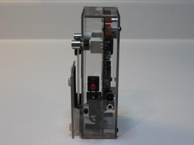
1 Elecraft W1 SWR/Wattmeter Enclosure by W8FGU The W1 enclosure is made of Lexan, a polycarbonate, which is very strong. It also has a UV blocking coating on one side and was assembled carefully with this side on the outside of the enclosure. Lexan is more shatterproof than acrylic (Plexiglas etc.) but is more prone to scratching than acrylic. Since my design goal was to use the W1 for portable applications, being exposed to dropping and falling off a table, I decided to go with the strength of a polycarbonate material. There are three different designs of the enclosure to incorporate three different mounting methods of the BNC connectors (J1 & J2) to the W1 printed circuit board. They are: Top mounted, right angle BNC connectors (as supplied in the W1 kit). Bottom mounted, right angle BNC connectors (as supplied in the W1 kit) Bottom mounted, straight through BNC connectors (as supplied by W8FGU or Digi-Key part number A32246-ND or Mouser Electronics part number ) The first version is slightly thicker and designed to house W1 kits already built per the Elecraft W1 manual for use without an enclosure. It is still recommended to mount the battery connector on the back of the W1 PCB for regardless of the version to make it easier to change the battery when needed. If you have not yet built the W1 (or at least not mounted the BNC connectors to the top of the PCB) it is recommended to mount the BNC connectors (right angle or straight through, whichever is desired) on the back of the PCB and install it in the bottom mounted BNC versions of the enclosure. The power switch was also externalized to the side of the enclosure. A supplied, small push button SPST switch was mounted on the connector side of the enclosure and wired directly to the W1 PCB for power switching. The existing PCB mounted DPDT switch should be set in the off position.
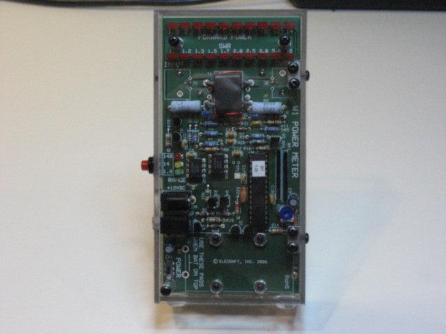
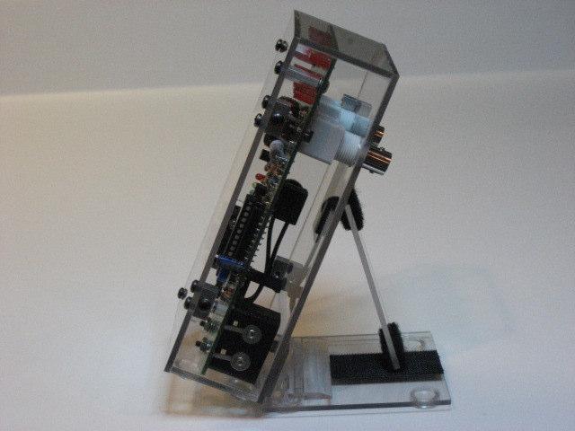
2 All LED s are clearly visible in the enclosure and it may be tilted to any desired angle for viewing via a separately purchased custom tilt stand mounted to the back of the enclosure. The tilt stand can be folded flat to the back of the enclosure when not in use for easy and efficient storage. Plastic feet on the bottom of the enclosure and the tilt stand, keep the enclosure from moving around on hard surfaces. The angle is adjusted with the tilt support piece fitted with Velcro on both ends. There are reciprocating pieces of Velcro mounted on the tilt stand and the back of the enclosure. The tilt support piece can be laid flat between the stand and the back, secured with the Velcro for storage. This also helps to prevent it s misplacement. The enclosure is constructed in two halves. These two halves are secured together via Elecraft custom 2-D fasteners and black anodized 4-40 screws. The top half contains the W1 PCB mounted to it via standoffs and the side that contains access to the power and data connector as well as the power switch. The bottom half contains the remaining side, ends and back of the assembly. Access to the inside of the enclosure is made by removing the four screws on the sides. Pulling the top half to the side for right angle BNC connectors or straight out of the enclosure for straight through BNC connectors, allows for changing the battery or access to the PCB. During initial installation, be aware that the enclosure has been designed with tight tolerances with regard to the internal size of the enclosure as it relates to the size of the W1 PCB. Keeping the mounting hardware loose until everything is lined up will help make sure the PCB is oriented properly. There is enough tolerance built into the size of the mounting holes to allow for slight adjustments during installation and insure that all of the enclosure edges are square and seams tight. It should be noted that two hole side of the custom 2-D fasteners are drilled slightly off center. The holes in the enclosure for mounting the 2-D fasteners are aligned so that the thicker side of the 2- D fastener is positioned at the outside edge of the enclosure half.

3 All mounting hardware is provided for mounting the W1 into the enclosure as well as the externalized power switch. All parts are listed below: 3 1/2 hex standoffs lock washers /4 screws 4 custom 2-D fasteners 15 black anodized 3/16 screws 1 SPST power switch with red button Top half of enclosure with power switch and standoffs mounted Bottom half of enclosure with tilt stand mounted The enclosure is shipped assembled with the 2-D fasteners and black anodized screws. The W1 Enclosure Version with top mounted, right angle BNC s. (Courtesy of Ron D Eau Claire).

4 Pre-Installation Notes Battery Holder Regardless of the enclosure version you have chosen, it is strongly recommended to mount the battery holder on the back of the W1 PCB. Even if you ve already mounted the battery holder on top, it may be easily removed and placed on the bottom. Care should be taken to insure that the terminals for the battery holder are mounted to the clearly marked holes on the back of the PCB and not the holes for mounting it on top. Before soldering the terminal connections, secure the battery holder with the mounting screws and properly align the holder on the PCB, then solder the terminals in place. Rubber Feet If you previously built your W1 with the rubber feet installed, they will need to be removed to expose the PCB mounting holes for installation with the provided standoffs and hardware.


5 Installation Separate the enclosure by removing the four side screws. Place the halves on something soft to prevent scratching them. Remove the Enclosure PCB mounting screws and standoffs from the top half. Separate the standoffs from their PCB mounting screws and lock washers. Mount the standoffs to the top side of the PCB in the three mounting holes. Place the lock washers between the standoff and the PCB and screw from the bottom of the PCB. Locate the PCB power switch, SW1, and insure that it is in the off position. PCB Mounting Screws Side Screws Side Screws With the top half facing down, place the PCB on the enclosure near its intended orientation within the enclosure. Locate U3 pin 1 and the junction of D4 and D5. Cut the switch wires for fit and tin the ends of the wires.


6 Solder one wire to U3 pin 1 by holding the wire with one hand and apply the soldering iron to the pad just until the solder melts. Repeat this process for the other wire soldered to the junction pads of D4 and D5. Orientation of the switch wires is not important. Insert the data port connector through its mounting hole in the side of the top half of the enclosure. If your BNC connectors are side mounted, insert this connector through the side panel as well. Secure the connector to the side panel with the connector mounting nut. Do not tighten the nut at this time. (In some cases, the data port connector may not protrude completely through the side panel, prohibiting the application of the mounting nut. This is of no concern since the mounting nut is not necessary in mounting the PCB to the enclosure. Simply leave off the mounting nut). Secure the PCB to the enclosure with three black anodized screws in their respective mounting holes. Do not tighten the screws at this time. You may also want to install the battery at this time. Data port connector Again, be sure that the PCB power switch, SW1, is in the off position before assembling the enclosure.
7 Assemble the two halves of the enclosure by feeding the BNC connectors through the rear holes (for the rear mounted connectors) or through the remaining hole in the side of the bottom half. Secure the halves together with the four side screws. Insure that all of the seams of the enclosure are tight and that all of the edges of the enclosure line up. Hand tighten each of the side screws. Now hand tighten the PCB mounting screws on the face insuring that the PCB is squared inside the enclosure. If using the data port mounting nut, tighten the mounting nut as well, again only hand tight. Do not overtighten. The installation is now complete. To replace the battery or gain access to the PCB, simply remove the four side screws and pull the halves apart.
8 Miscellaneous Pictures
Star Trac Fitness E-ST 5090 Stepper. Install Guide
 Star Trac Fitness E-ST 5090 Stepper Install Guide STAR TRAC E-ST STEPPER Install Guide E-ST 5090 E Series Stepper ASSEMBLY AND SETUP The following parts are included with the base STAR TRAC E-ST STEPPER:
Quicksilver 606 TR-606 CPU Upgrade
 Quicksilver 606 TR-606 CPU Upgrade D650C 128 Installation Guide Social Entropy Electronic Music Instruments TABLE OF CONTENTS WARNINGS... 1 OVERVIEW... 2 WHAT'S IN THE BOX... 3 OPENING THE TR-606 CASE...
FieldKit DIY Manual Author: Otto Mikkonen Last updated:
 FieldKit DIY Manual Author: Otto Mikkonen Last updated: 11.04.2017 Required Materials - 1 x FieldKit PCB - 1 x FieldKit Front Panel - 1 x FieldKit Wooden Enclosure (Bottom + Lid) - 4 x Small Bottom Pad
Elecraft K3 KPA3 Power Connector Replacement Revision B, June 30, 2017 Copyright 2017, Elecraft, Inc. All Rights Reserved
 Introduction Elecraft K3 KPA3 Power Connector Replacement Revision B, June 30, 2017 Copyright 2017, Elecraft, Inc. All Rights Reserved The connectors furnishing high current to the KPA3 module have failed
IQ32 Upgrade Kit Assembly Instructions
 IQ32 Upgrade Kit Assembly Instructions Jim Veatch WA2EUJ September 17, 2018 TABLE OF CONTENTS 1. INTRODUCTION... 3 2. IQ-32 UPGRADE KIT INVENTORY... 4 3. PREPARING THE RS-HFIQ AND SIDE PANELS... 6 4. CONNECTING
CINTENNA ANTENNA REPAIR GUIDE
 The Cintenna is a great tool when looking to transmit WIRELESS DMX data over obstacles or hard to reach places. Wireless DMX can have its issues when not having a good line of sight between the transmitter
Addendum to the Actalyst Interactive Digital Signage Installation and User s Guide
 Addendum to the Actalyst Interactive Digital Signage Installation and User s Guide This addendum contains information about the Actalyst Interactive Overlay that has changed since the release of the Actalyst
Installation Guide. Retrofit Kit for USB Ready Intraoral Systems
 Installation Guide Retrofit Kit for USB Ready Intraoral Systems Table of Contents Wall-Mount Retrofit Kit... 2 Introduction... 2 Connecting the Articulating and Horizontal Arm Cables... 2 Installing the
Tubbutec Sumtiple Kit Version Construction Manual
 Tubbutec Sumtiple Kit Version Construction Manual This document describes the construction of the Sumtiple Kit. The following parts are included: 1x Sumtiple PCB with SMD-Parts already soldered 1x Front
Navigator II INstallatIoN MaNUal For static and PaN/tIlt configurations
 Navigator II Installation MANUAL For Static and Pan/Tilt Configurations Document Number: 432-0001-00-12, rev 100 FLIR Systems, Inc., 2008. All rights reserved worldwide. No parts of this manual, in whole
Part 2: Building the Controller Board
 v3.01, June 2018 1 Part 2: Building the Controller Board Congratulations for making it this far! The controller board uses smaller components than the wing boards, which believe it or not, means that everything
INSTRUCTIONS FOR THE INSTALLATION OF THE INFINITY "L" DISPLAY HOOD (INTO PREVIOUSLY INSTALLED INFINITY "L" SYSTEMS)
") Doc. 6001025 Rev B INSTRUCTIONS FOR THE INSTALLATION OF THE INFINITY "L" DISPLAY HOOD (INTO PREVIOUSLY INSTALLED INFINITY "L" SYSTEMS) Rev. B Doc. 6001025 Page 1 of 13 IMPORTANT NOTICE This document covers
Doc. 6001025 Rev B INSTRUCTIONS FOR THE INSTALLATION OF THE INFINITY "L" DISPLAY HOOD (INTO PREVIOUSLY INSTALLED INFINITY "L" SYSTEMS) Rev. B Doc. 6001025 Page 1 of 13 IMPORTANT NOTICE This document covers
TECHKNOW, INC. Kiosk Order Confirmation System INSTALLATION MANUAL. Revision Date: July 11, 2012 Part # Version 3.2
 document Page 1 of 18 TECHKNOW, INC Kiosk Order Confirmation System INSTALLATION MANUAL Revision Date: July 11, 2012 Part # Version 3.2 Techknow, Inc. 393 Mayfield Road Duncan, SC 29334 www.gotechknow.com
How to assemble and disassemble Anafi
 How to assemble and disassemble Anafi Prerequisites The best way to repair ANAFI is to use Parrot official drones repair kit. You will need the cruciform as well as the Torx 5 (T5) in order to carry out
Q2 XBee Handheld Controller Assembly Guide
 Q2 XBee Handheld Controller Assembly Guide Copyright Quantum Robotics Inc. Q2 Controller V1.0 1 Parts List: The kit comes with 14 individual bags. 1. Case Top and Bottom 2. Case Screw Package containing:
Construction Construction Instructions
 Semi-Virtual Diskette SVD Construction Construction Instructions PCB version 2.0 September 2004 Eric J. Rothfus Table of Contents Table of Contents... i Parts List...1 Construction Overview...5 PCB Construction...
Formulate Designer Series 20 Backwall - Kit 11
 Formulate Designer Series 20 Backwall - Kit 11 FMLT-DS-20-11 Formulate Designer Series 20ft displays have unique stylistic features and shapes, are portable and easy to assemble. The aluminum tube frame
Elecraft K3 KREF3 Output Level Modification
 Elecraft K3 Revision A, September 15, 2015 Copyright 2015, Elecraft, Inc. All Rights Reserved Introduction This modification increases the output levels from the KREF3 Reference Oscillator to provide proper
SNA KIT Assembly Guide
 SNA KIT Assembly Guide Ver 0.8 April 2015 Note: Many references still exist to the SNA Kit s predecessor (NAT Kit). Also, the parts and additional steps used to make the NAT an SNA have not yet been shown
MCH WIRE HARNESS WITH QUICK DISCONNECT REPLACEMENT Initial Release 1/31/2013
 1. Table of Contents 1. Table of Contents Page 1 2. Remove Failed MCH-103.2 Page 1 3. Install MCH-103.2 to MCH-102NW Page 2 4. Install NC3FX-HD to MCH-103.2 Page 3 5. Install MCH-103.2 Battery Terminal
Populating and Installing Synthex Rev 2/3 EPROM adapter board. R Grieb 5/13/2018
 Populating and Installing Synthex Rev 2/3 EPROM adapter board. R Grieb 5/13/2018 Please read these instructions before purchasing or installing the EPROM adapter, to make sure you are comfortable performing
TIME WIZARD MULTI CLOCK DIVIDER BUILDING GUIDE
 TIME WIZARD MULTI CLOCK DIVIDER BUILDING GUIDE Table of Contents 0. Components List + Tools 0. PCB Sides 03. PCB Assembly 04_. Diode N448 04_. Laying Resistors 04_3. Capacitors 04_4. Quartz 04_5. 78L05
PiJuice Quick Start Guide and FAQ. Getting started. Kit contents
 PiJuice Quick Start Guide and FAQ Getting started As one of the smallest systems around there are so many amazing things you could do with the Raspberry Pi if it was self-powered and portable. Introducing
Phi-panel backpack assembly and keypad options Dr. John Liu 12/16/2012
 Phi-panel backpack assembly and keypad options Dr. John Liu 12/16/2012 1. Introduction:... 3 Currently available:... 3 2. Backpack assembly... 4 3. Connecting to a keypad... 6 4. Rotary encoder keypads...
Portable Qi Charger. Created by Ruiz Brothers. Last updated on :20:38 AM UTC
 Portable Qi Charger Created by Ruiz Brothers Last updated on 2017-12-05 01:20:38 AM UTC Guide Contents Guide Contents Overview Prerequisite Guides Parts, Tool & Supplies Universal Qi Wireless Charging
How to build an Olympus D-360L Trail Camera using the PixController Universal "Digital Trail Camera Kit" w/ RS-232-U PIC Chip
 Copyright, PixController, Inc. http://www.pixcontroller.com, all rights reserved. How to build an Olympus D-360L Trail Camera using the PixController Universal "Digital Trail Camera Kit" w/ RS-232-U PIC
SDR Cube Transceiver Online Assembly Guide
 Page 1 of 13 SDR Cube Transceiver Online Assembly Guide Detailed construction notes for building and testing the SDR Cube Kit Home Bill of Materials I/O Board Controls Board DSP Board Softrock SR-Base
Effects Loop Installation Guide
 Warnings and Disclaimer Effects Loop Installation Guide You will be working with HIGH VOLTAGE. These voltages CAN BE DEADLY if you are not extremely careful. If you are not comfortable working with HIGH
OpenSprinkler v2.2u Build Instructions
 OpenSprinkler v2.2u Build Instructions (Note: all images below are 'clickable', in order for you to see the full-resolution details. ) Part 0: Parts Check Part 1: Soldering Part 2: Testing Part 3: Enclosure
Treadmill Integrated LCD Screen Option. Cardio Theater Integrated Bracket Assembly Instructions
 Treadmill Integrated LCD Screen Option Cardio Theater Integrated Bracket Assembly Instructions Table of Contents 1 2 3 4 5 6 Before You Begin... 4 Obtaining Service... 4 Unpacking the Equipment... 4 Important
edrive RAM Battery Alternate Replacement Procedure
 edrive RAM Battery Summary This technical note describes the process for replacing the TINI RAM battery with a higher capacity battery. With the edrive turned on, the external battery can be changed without
G12/G12x USER S MANUAL
 G12/G12x USER S MANUAL TABLE OF CONTENTS SECTION 1 SLIDE CONFIGURATION SECTION 2 SLIDE CONFIGURATION ACCESSORIES SECTION 3 TABLETOP CONFIGURATION SECTION 4 TABLETOP CONFIGURATION ACCESSORIES SECTION 5
IS-DM220/IR/HB IS-DM220
 IS-DM220/IR/HB IS-DM220 Installation Guide Indoor/Outdoor Ver. 1.2 00P6NX223ZXSEA2 Table of Contents 1. Indoor Camera Installation... 3 1.1 Hard Ceiling... 3 1.2 In-Ceiling (T-Bar) Mounting... 13 1.3 4S
Pacific Antenna Two Tone Generator
 Pacific Antenna Two Tone Generator Description Our Two Tone Generator kit provides two non-harmonic, sine wave signals for testing audio circuits Outputs of approximately 700Hz and 1900Hz and the combination
Mikrokopter FPV Camera Mount. Assembly Manual
 Assembly Manual Introduction Thank you for purchasing the. The FPV Camera Mount is provided as a kit and requires assembly. The assembly of the mount can take up to 15-20 minutes for an inexperienced builder.
B&W RearView Camera Installation & Operation
 B&W RearView Camera Installation & Operation CA52 (Camera) FOR MORE INFORMATION WWW.STRATEGICVISTA.COM BEFORE OPERATING THIS SYSTEM, PLEASE READ THIS MANUAL THOROUGHLY AND RETAIN IT FOR FUTURE REFERENCE
K2 RIT-SPLIT LED Indicator Mod dated 18 October 2003 Circuit Design by: Wayne Burdick, N6KR Implementation by: Tom Hammond, NØSS
 K2 RIT-SPLIT LED Indicator Mod dated 18 October 2003 Circuit Design by: Wayne Burdick, N6KR Implementation by: Tom Hammond, NØSS Show & Tell Pictorial Supplement to the K2 RIT-SPLIT LED Mod Documentation
FITTING INSTRUCTIONS
 & This option connects a GL3000 or GL3300 console as a channel expander to a second console with just one or two interconnecting cables. Kit Part No: GL3000-SL1 Single option to install SYS-LINK to one
Megatouch FORCE Monitor Chassis Board Replacement
 Megatouch FORCE Monitor Chassis Board Replacement Visit the Merit Industries, Inc. Web site http://www.meritind.com merit industries, inc. PM0337-01 Rev C Table of Contents FORCE Classic Monitor Chassis
Assembly Instructions Triton Enclosure for Poseidon With Data Acquisition November, 2007 V0.9 DSC Document #
 Assembly Instructions Triton Enclosure for Poseidon With Data Acquisition November, 2007 V0.9 DSC Document #7521002 Diamond Systems Corp. (650) 810-2500 www.diamondsystems.com This document describes how
E2460GS Oscilloscope Upgrade Kit
 Installation Instructions for E2460GS Oscilloscope Upgrade Kit Agilent 1670G-Series Logic Analyzers This kit upgrades either the Agilent Technologies 1670G, Agilent 1671G, Agilent 1672G, or the Agilent
OnePlus 5 Screen and Digitizer Assembly Replacement
 OnePlus 5 Screen and Digitizer Assembly Replacement Follow this guide to replace the screen and digitizer for the OnePlus 5. This replaces the screen as well as the frame it is attached to. Written By:
OpenSprinkler v2.1u Build Instructions
 OpenSprinkler v2.1u Build Instructions (Note: all images below are 'clickable', in order for you to see the full-resolution details. ) Part 0: Parts Check Part 1: Soldering Part 2: Testing Part 3: Enclosure
[Note: Power adapter is not included in the kits. Users need to prepare a 9 12 V ( >300mA capacity ) DC power supply]
![[Note: Power adapter is not included in the kits. Users need to prepare a 9 12 V ( >300mA capacity ) DC power supply]](/thumbs/76/74094055.jpg "[Note: Power adapter is not included in the kits. Users need to prepare a 9 12 V ( >300mA capacity ) DC power supply]") 062 LCD Oscilloscope Assembly Notes Applicable Models: 06203KP, 06204KP DN062-18v02 Important Notes 1. Some components shown in the schematic and PCB layout are for options or adjustments. They do not
062 LCD Oscilloscope Assembly Notes Applicable Models: 06203KP, 06204KP DN062-18v02 Important Notes 1. Some components shown in the schematic and PCB layout are for options or adjustments. They do not
Replace the edrive TINI Module and Battery
 Product All edrive Configurations Special Information INFORMATION: This service bulletin is for informational purposes only. It is intended for use by Northrop Grumman Cutting Edge Optronics (NG CEO) employees
FortiCam FD40 Mounting Guide
 FortiCam FD40 Mounting Guide 1 FORTINET DOCUMENT LIBRARY http://docs.fortinet.com FORTINET VIDEO GUIDE http://video.fortinet.com FORTINET BLOG https://blog.fortinet.com CUSTOMER SERVICE & SUPPORT https://support.fortinet.com
Parts and Service Manual IMCO
 XXTREME ADVANTAGE Gimbal Parts and Service Manual IMCO 510 East Arrow Highway San Dimas, CA 91773 (800) 899-8058 (909) 592-6162 Fax (909) 592-6052 www.imcomarine.com email info@imcomarine.com TABLE OF
Installing the Server into a Rack
 Installing the Server into a Rack Note These instructions apply to multiple models; illustrations may vary slightly. Rack Mount Kit Inventory Before installing the chassis on a standard 4-post rack, make
Connecting Mitutoyo Digimatic Devices to the Caliper2PC Interface A step by step Guide
 Mitutoyo Digimatic Devices Mitutoyo is one of the world's leading manufacturers of precision measuring equipment, offering a huge range of professional products from micrometers, calipers to dial gauges.
Pandora Assembly Instructions With Diamond Systems PC/104 CPUs (Athena, Elektra and Prometheus) November, 2006
 November, 2006") Pandora Assembly Instructions With Diamond Systems PC/104 CPUs (Athena, Elektra and Prometheus) November, 2006 Diamond Systems Corp. (650) 810-2500 www.diamondsystems.com This document describes how to
Pandora Assembly Instructions With Diamond Systems PC/104 CPUs (Athena, Elektra and Prometheus) November, 2006 Diamond Systems Corp. (650) 810-2500 www.diamondsystems.com This document describes how to
Mac Mini Mid 2010 SSD Installation
 Mac Mini Mid 2010 SSD Installation Replace your Mac Mini Mid 2010's hard drive for more storage space and an increase in speed. Written By: Dozuki System 2017 guides.crucial.com Page 1 of 15 INTRODUCTION
High Power (15W + 15W) Stereo Amplifier
 Stereo Amplifier") High Power (15W + 15W) Stereo Amplifier Build Instructions Issue 1.0 Build Instructions Before you put any components in the board or pick up the soldering iron, just take a look at the Printed Circuit
High Power (15W + 15W) Stereo Amplifier Build Instructions Issue 1.0 Build Instructions Before you put any components in the board or pick up the soldering iron, just take a look at the Printed Circuit
Packaging the Elecraft XG2 Receiver Test Oscillator and 2T -gen 2-Tone Test Oscillator Phil Salas AD5X
 Packaging the Elecraft XG2 Receiver Test Oscillator and 2T -gen 2-Tone Test Oscillator Phil Salas AD5X My two recent test equipment additions are the Elecraft XG2 Receiver Test Oscillator, and the Elecraft
TABLE OF CONTENTS SECTION 1 TABLETOP CONFIGURATION SECTION 2 TABLETOP CONFIGURATION ACCESSORIES SECTION 3 SLIDE CONFIGURATION
 S6 USER S MANUAL TABLE OF CONTENTS SECTION 1 TABLETOP CONFIGURATION SECTION 2 TABLETOP CONFIGURATION ACCESSORIES SECTION 3 SLIDE CONFIGURATION SECTION 4 SLIDE CONFIGURATION ACCESSORIES SECTION 5 RACK MOUNT
Z-Truck (Vertical Moving) Z-truck Flag. Y-Truck (Horizontal Moving) FIGURE 1: VIEW OF THE Z-TRUCK. Flexshaft Assembly
 Z-truck Flag. Y-Truck (Horizontal Moving) FIGURE 1: VIEW OF THE Z-TRUCK. Flexshaft Assembly") Replacing the LCD Cable To remove and replace the LCD Cable you will need the following tools: #2 Phillips screwdriver (magnetic tip preferred) Socket wrench with 10mm socket Removing the Side Panel 1.
Replacing the LCD Cable To remove and replace the LCD Cable you will need the following tools: #2 Phillips screwdriver (magnetic tip preferred) Socket wrench with 10mm socket Removing the Side Panel 1.
ITS-Z0344 Half Pitch Interface Connectors
 All non- product have been discontinued, or will be discontinued soon. Please check the products status on the Hirose website search at www.hirose-connectors.com, or contact your Hirose sales representative.
RETROAKTIv PG-800 MINI. Installation Manual & User Guide CONTROLLER FOR ROLAND JX-8P, SUPER JX & MKS Retroaktiv LLC, all rights reserved.
 RETROAKTIv PG-800 MINI CONTROLLER FOR ROLAND JX-8P, SUPER JX & MKS-70 Installation Manual & User Guide 2017 Retroaktiv LLC, all rights reserved. CONTENTS GETTING STARTED 3 FEATURES 4 PCB BUILD NOTES 5
EQ573 Assembly guide. EQ573 Assembly guide Main board 1. Diodes. 2. Resistors (1) 3. Test pins. 4. Ceramic capacitors.
 3. Test pins. 4. Ceramic capacitors.") EQ573 Assembly guide Safety warning The kits are main powered and use potentially lethal voltages. Under no circumstance should someone undertake the realisation of a kit unless he has full knowledge about
EQ573 Assembly guide Safety warning The kits are main powered and use potentially lethal voltages. Under no circumstance should someone undertake the realisation of a kit unless he has full knowledge about
Seeburg JCU-DEC Kit Convert Your Seeburg DEC Wallbox Into a Jukebox
 Seeburg JCU-DEC Kit Convert Your Seeburg DEC Wallbox Into a Jukebox MP3 Compact Flash Player Coin Operated or Free Play Integrated Power Amplifier Line-Out to External Amplifier Programmable Autoplay IR
NewScope-7B Operating Manual
 2016 SIMMCONN Labs, LLC All rights reserved NewScope-7B Operating Manual Preliminary May 13, 2017 NewScope-7B Operating Manual 1 Introduction... 3 1.1 Kit compatibility... 3 2 Initial Inspection... 4 3
Supplemental guide on Camera Fabrication
 Supplemental guide on Camera Fabrication This document describes the steps for fabricating your camera and lighting system. 1 Materials needed Gather all your materials. You will need the small lexan sheet
xtablet T1600 Vehicle Holder Installation Guide
 This document will step you through setting up the T1600 Vehicle Holder installation and tips for a safe, clean and long lasting installation. Preparing to Mount the Vehicle Holder Warning : Dock mounting
Section 5: Installing Parts from the Controls and Connectors Bag
 Section 5: Installing Parts from the Controls and Connectors Bag 1) Install Pinheaders & Sockets Using the Component Layout Diagram in Appendix A as a guide, install all pinheaders and strip sockets on
ELECRAFT K3 HIGH-PERFORMANCE METER TRANSCEIVER K3EXREF FREQUENCY LOCK OPTION INSTALLATION AND OPERATION. Revision A2, October 31, 2012
 ELECRAFT K3 HIGH-PERFORMANCE 160 6 METER TRANSCEIVER K3EXREF FREQUENCY LOCK OPTION INSTALLATION AND OPERATION Revision A2, October 31, 2012 Copyright 2012, Elecraft, Inc. All Rights Reserved Contents Introduction...
PowerAmp Design EVAL117 EVALUATION KIT FOR PAD117A
 EVALUATION KIT FOR PAD117A INTRODUCTION The EVAL117 evaluation kit provides a convenient method to become familiar with the operation of the PAD117A operational amplifier before your application circuit
TDM To MiniMech conversion ProceDure
 TDM To MiniMech conversion ProceDure (Model 9100 ATM) TDN 07102-00079 Apr 1 2009 CorporATe HeAdquArTers: 522 E. Railroad Street Long Beach, MS 39560 PHONE: (228) 868-1317 FAX: (228) 868-0437 COPYRIGHT
Blackout Shutter Kits with Breathable Wall Light Traps
 Blackout Shutter Kits with Breathable Wall Light Traps 2018 Growers Supply All Rights Reserved. Reproduction is prohibited without permission. Maintain controlled airflow without sacrificing blackout environments.
Linear Kiosk 02. features and benefits: dimensions: additional information:
 Linear Kiosk 02 LN-K-02 Dress up and add wow to your space with state-of-the-art multimedia kiosks. features and benefits: - Custom appearance - Easy to assemble - Bases available in four finishes - Aluminum
Revised: Page 1
 Brought To You By And Designed By: Revised: 2017-05-07 Page 1 Features Of The Universal PSU Kit: Fits all standard Apple II and /// Power Supply Enclosures. (all parts included, user supplies household
ELECRAFT K3S HIGH-PERFORMANCE METER TRANSCEIVER KAT3A 100-WATT AUTOMATIC ANTENNA TUNER INSTALLATION INSTRUCTIONS. Rev A, June 2, 2015
 HIGH-PERFORMANCE 160 6 METER TRANSCEIVER ELECRAFT K3S KAT3A 100-WATT AUTOMATIC ANTENNA TUNER INSTALLATION INSTRUCTIONS Rev A, June 2, 2015 Copyright 2015, Elecraft, Inc. All Rights Reserved E740266 Contents
CIB 3047 (14B) 10-Button Voice Terminal Fixed Desk Stand and Wall Mount (32007)
 10-Button Voice Terminal Fixed Desk Stand and Wall Mount (32007)") CIB 3047 (14B) 10-Button Voice Terminal Fixed Desk Stand and Wall Mount (32007) CIB 3047 Comcode 845-659-325 Issue 1 CIB 3047 (14B) 10-Button Voice Terminal Fixed Desk Stand and Wall Mount (32007) This
CIB 3047 (14B) 10-Button Voice Terminal Fixed Desk Stand and Wall Mount (32007) CIB 3047 Comcode 845-659-325 Issue 1 CIB 3047 (14B) 10-Button Voice Terminal Fixed Desk Stand and Wall Mount (32007) This
PowerAmp Design. PowerAmp Design EVAL127 EVALUATION KIT FOR PAD127/157. Rev G
 PowerAmp Design EVALUATION KIT FOR PAD7/57 EVAL7 Rev G INTRODUCTION The EVAL7 assembled evaluation kit provides a convenient method to become familiar with the operation of the PAD7/57 operational amplifiers
TIVO DVR UPGRADE INSTRUCTIONS (#80-HD)
") TIVO DVR UPGRADE INSTRUCTIONS (#80-HD) (c) 2001-2006, weaknees. All rights reserved. Instructions for TwinBreeze HR10-250 DVR Upgrade Bracket/Kit Instructions are available online (in COLOR) at http://www.weaknees.com
TIVO DVR UPGRADE INSTRUCTIONS (#80-HD) (c) 2001-2006, weaknees. All rights reserved. Instructions for TwinBreeze HR10-250 DVR Upgrade Bracket/Kit Instructions are available online (in COLOR) at http://www.weaknees.com
Installing PRO/DGX or Pro Soloist MIDI interface. R Grieb 9/08/2017
 Installing PRO/DGX or Pro Soloist MIDI interface. R Grieb 9/08/2017 Please read these instructions before purchasing the MIDI interface, to make sure you are comfortable performing the necessary steps.
RAM Rail Mount Kit RAM 201U 5 Arm RAM 2461U Monitor Mount RAM 235U Base, Double U-Bolt
 Note: Indented items indicate parts included in an assembly listed above Part Name/Description Part Number Quantity DirectCommand Kit 4100800 1 Cable Installation Kit 2000901-1 1 Dielectric Grease 2002872
Pan-Tilt-Zoom Security Camera
 Security Made Smarter Pan-Tilt-Zoom Security Camera For use with Swann Pro-Series 080p DVRs EN INSTRUCTION MANUAL M080VERE Swann 07 7 5 8 6 4 VIDEO INPUT 4 INPUT OUTPUT VGA RS485 LAN V Step One - Introduction
Casio CZ. Non volatile memory modification Installation instructions version copyright 2013 Artefacts
 Casio CZ Non volatile memory modification Installation instructions version 2.0 2017 www.artefacts.nl copyright 2013 Artefacts Introduction The Casio CZ-101 and CZ-1000 do not have a separate backup battery
Written By: Walter Galan
 Replace a cracked screen on your iphone 4S. Written By: Walter Galan ifixit CC BY-NC-SA www.ifixit.com Page 1 of 32 INTRODUCTION Use this guide to replace the screen on your iphone 4S. After successfully
imac Intel 27" EMC 2429 SSD Dual Drive
 imac Intel 27" EMC 2429 SSD Dual Drive Installation Install the dual hard drive kit in an imac Intel 27" EMC 2429. Written By: Dozuki System 2017 guides.crucial.com Page 1 of 22 INTRODUCTION This guide
WinKey USB SMT Assembly Guide Version /26/2017
 WinKey USB SMT Assembly Guide Version 1.5 12/26/2017 This document describes the assembly and testing of the K1EL Winkey USB Keyer Kit with a version 01 SMT PCB. In this new design, surface mount components
VPC-64/ VPX-64 VIDEO POLE CAMERA OPERATION MANUAL
 VPC-64/ VPX-64 VIDEO POLE CAMERA OPERATION MANUAL RESEARCH ELECTRONICS INTERNATIONAL 455 Security Drive Algood, TN 38506 U.S.A. +1 931-537-6032 http://www.reiusa.net/ COPYRIGHT RESEARCH ELECTRONICS INTERNATIONAL
**** Never plug in your LED driver to AC power until all wiring is complete ****
 1 RapidLED Plug-n-Play Solderless Retrofit Kit Contents Overview... 1 Warnings Read Me First!... 1 Dimmable Driver Controller and Driver Output Current Adjustment... 2 Kit Assembly... 2 Attaching Your
Shop Fox Fence Kit Installation Instructions:
 Shop Fox Fence Kit Installation Instructions: Please note this installation kit is designed solely for installation on a Shop Fox Classic Fence. Accurate Technology manufactures kits for other saw fences
Assembly Guide. LEDs. With these assembly instructions, you can easily build your own SWT16. All required components are included in this kit.
 Assembly Guide With these assembly instructions, you can easily build your own SWT16. All required components are included in this kit. You need the following tools: soldering iron, wire cutter and solder.
USBCNC-SW USB Disk Key reader for CNC Controls Machine Mount instructions for Universal Switcher Version
 USBCNC-SW USB Disk Key reader for CNC Controls Machine Mount instructions for Universal Switcher Version 2015 Calmotion LLC, All rights reserved Calmotion LLC 21720 Marilla Street Chatsworth, CA 91311
ELECRAFT P3 HIGH-PERFORMANCE PANADAPTER P3SVGA OPTION INSTALLATION AND OPERATING INSTRUCTIONS. Rev B, March 20, 2012
 ELECRAFT P3 HIGH-PERFORMANCE PANADAPTER P3SVGA OPTION INSTALLATION AND OPERATING INSTRUCTIONS Rev B, March 20, 2012 Copyright 2012, Elecraft, Inc. All Rights Reserved Contents Introduction... 3 Customer
Required Tools. Ford Transit Connect J4075 with R16 Tracks TRANSIT CONNECT 69 RAIL IBI. Marker. 7/16 / 9/16 / 1/2 Wrench.
 IBI Required Tools INSTRUCTION MANUAL Marker 7/16 / 9/16 / 1/2 Wrench Drill with 3/8 Drill Bit Allen Key Ford Transit Connect J075 with R16 Tracks Part # J075 Rails 96 Bars 55 [ ] BLACK WHITE SILVER [
ASSET LGA1366 Top-side Probe
 ASSET LGA1366 Top-side Probe (Manual version 1.1) For gaining test access to the debug port of Intel processors that are designed for use in LGA1366 Sockets (Socket B). These include the Intel Core i7
FCC17 Series FILTERED STACKED D-SUB CONNECTORS
 FCC17 Series FILTERED STACKED D-SUB CONNECTORS Ordering Information Stacked D-Sub FCC17 2 BP BS 4 5 5 X FCC17 2 VERTICAL MOUNTING DIMENSION BETWEEN CONNECTORS 1 =.625" [15.88 mm] 2 =.750" [19.05 mm] BP
Ultimate LPF kit: Relay-switched LPF kit
 Ultimate LPF kit: Relay-switched LPF kit PCB Revision 4 1. Introduction Thank you for purchasing the QRP Labs relay-switched low-pass filter (LPF) kit. This kit is designed to complement the Ultimate3
Upgrade Instructions Printer Terminal Holder
 Upgrade Instructions 6820 Printer Terminal Holder Instructions Terminal Holder Installation Kit The terminal holder connects INTERMEC R computers to the 6820 Printer. Do these instructions, in the order
ISOLATION RELAY RACK ISOLATION KIT 19 RACK MOUNT RELAY RACK ISOLATION KIT, SLOTTED UNEQUAL FLANGE RACK ISOLATION KIT 23 RACK MOUNT
 ISOLATION Info: 9070 = Isolation RELAY RACK ISOLATION KIT 19 RACK MOUNT 9070-1019 19" Rack Mount 23 RACK MOUNT 9070-1023 23" Rack Mount RELAY RACK ISOLATION (KIT) RELAY RACK ISOLATION KIT, SLOTTED 19 RACK
Removing and Replacing Parts
 Removing and Replacing Parts Preparing to Work Inside the Computer Recommended Tools Screw Identification System Components Hard Drive Fixed Optical Drive Media Bay Devices Memory Modules Mini PCI Card
Canon Powershot A720 IS Motherboard Replacement
 Canon Powershot A720 IS Motherboard Replacement This guide will show how to replace the motherboard. Written By: Jamie ifixit CC BY-NC-SA www.ifixit.com Page 1 of 16 INTRODUCTION This guide will allow
FCB1010 Phantom Power Adaptor
 FCB1010 Phantom Power Adaptor The Behringer FCB1010 pedal is normally powered by an external cable that plugs into a standard 120 volt 3-prong wall receptacle. While this works fine, it does require a
Arc-Geo Mini Kit. The kit includes box, faceplate, PC board, All IC s, USB jack, 4 mhz resonator and programmed controller.
 Arc-Geo Mini Kit Thank you for purchasing the Arc-Geo mini KIT. I hope you will find many treasure with your new unit. The level of the kit is an 8 on a scale of 1-10. The reason of the 8 is a few surface
PowerAmp Design EVAL118. PowerAmp Design EVAL118 EVALUATION KIT FOR MODELS PAD115/ 118/ 119 EVALUATION KIT FOR MODELS PAD115/ PAD118/ PAD119.
 PowerAmp Design EVALUATION KIT FOR MODELS PAD115/ PAD118/ PAD119 Rev I INTRODUCTION The assembled evaluation kit provides a convenient method to become familiar with the operation of the operational amplifier
 This tutorial was written by Team Xecuter. If you use anything from this tutorial please give credits and also a direct link to this page. Also if we have made any mistakes or left anything out please
ILC LightLEEDer MicroLite 1000P Retrofit Installation
 ILC LightLEEDer MicroLite 1000P Retrofit Installation Congratulations on the purchase of your new ILC LightLEEDer Retrofit System. The ILC LightLEEDer MicroLite Retrofit System is designed for the replacement
SP-100. Service Manual Aug. 02
 SP-100 Service 2004. Aug. 02 1. Caution for maintenance and Service. Please take care below points when you do Service and Maintenance. (1) Service and Maintenance should be done under safety condition.