Automated Design Exploration and Optimization + HPC Best Practices
|
|
|
- Mary Short
- 5 years ago
- Views:
Transcription

1 Automated Design Exploration and Optimization + HPC Best Practices ANSYS, Inc. June 8, 2012 Laz Foley & Simon Pereira Confidence by Design Detroit June 5, 2012
2 Outline The Path to Robust Design ANSYS DesignXplorer Mesh Morphing and Optimizer RBF Morph Adjoint Solver HPC Best Practices


3 The Path to Robust Design bust Design is an SYS Advantage gle Physics lution curacy, robustness, ed Multiphysics Solution Integration Platform What if Study Parametric Platform Design Exploration DOE, Response Surfaces, Correlation, Sensitivity, Unified reporting, etc. Optimization Algorithms Published API Robust Design Six Sigma Analysis Probabilistic Algorithms Adjoint solver methods


4 Deformation Single Physics/Multi Physics physics is the entry point ulation Physics enables real l prototyping Fluid Pressure Distribution 2 way coupled with a transient structural solution Stress? magnetic Force Density with Thermal Stress and Electromagnetic Force load


5 What If? Interactively adjust the parameter values and Update Needed for "What If?" Parametric CAD Connections Pervasive Parameters Persistent Updates Managed State, Update Mechanisms Remote Solve Manager (RSM)


6 Design Exploration


7 Optimization Optimal Candidates


![674 1.709 η [%] 71.](/docs-images/90/103881212/images/8-4.jpg "65 76.25 Power [MW] 1.")

8 ANSYS DesignXplorer Initial vs. Optimized Design Output Initial Design Optimized T t Ratio p t Ratio η [%] Power [MW] Engineers can easily appreciate the value of understanding.


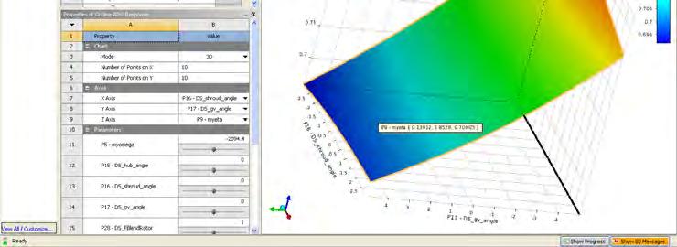
9 Uncertainty of input Response Surface showing the effect of engine speed and thickness at outlet on Thermal Stress Pressure & Flow Velocity Parametric Geometry ust manifold design Sigma Analysis um Displacement should not exceed 1.5 mm arameters Response Parameters Diameter of the Max Flow Temperature d Max Deformation ess at inlet Max Von Mises stress l Temperature RPM Deformation All samples reports max deformation below 1.5 mm
10 Where are you? may want to consider how far along the path your simulation practices are aps you could improve your use of optimization and greater leverage your investment in Simulation?


11 ANSYS DesignXplorer Integral with Workbench Parametric multiphysics modeling with automated updates Bi directional CAD, RSM, scripting, reporting and more...


12 Robust Design Tools at ANSYS SYS DesignXplorer nified Workbench solution SYS Fluent uilt in Mesh Morphing and hape Optimization (MMO) tools Being hooked up to DX for 14.5 djoint solver Baseline Design High sensitivity changes to shape have a big effect on drag Low sensitivity R14 Optimized Design High sensitivity Shape on Downforce

![Corporation Fm [newton] 350.00 300.00 250.00 200.00 150.00 100.](/docs-images/90/103881212/images/13-2.jpg "00 XY Plot 1 Maxwell3DDesign1 Curve Info Fm Setup1 : LastAdaptive Gap='0.")


13 Robust Design Tools at ANSYS SOFT Optimetrics roduce families of curves imultaneous solve with DSO packs ccess to EBU Adjoint d more Ansoft Corporation Fm [newton] XY Plot 1 Maxwell3DDesign1 Curve Info Fm Setup1 : LastAdaptive Gap='0.001in' Fm Setup1 : LastAdaptive Gap='0.002in' Fm Setup1 : LastAdaptive Gap='0.003in' Fm Setup1 : LastAdaptive Gap='0.004in' Fm Setup1 : LastAdaptive Gap='0.005in' Fm Setup1 : LastAdaptive Gap='0.006in' ampturns [A]
 ModeFrontier")
 Sigma Technology (IOSO) TOSCA (FE DESIGN) isight (Dassault) Qfin")
14 Optimization Partners SYS simulation software has been effectively used in concert with many optimization partners MATLAB (Mathworks) ModeFrontier (Esteco) OptiSLang (Dynardo) eartius Optimus (Noesis) RBF Morph Sculptor (Optimal) Sigma Technology (IOSO) TOSCA (FE DESIGN) isight (Dassault) Qfin (Qfinsoft)
15 ANSYS DesignXplorer


16 ANSYS DesignXplorer DesignXplorer is everything under this Parameter bar Low cost & easy to use! It drives Workbench Improves the ROI! ANSYS Workbench Solvers DX


17 Design of Experiments With little more effort than for a single run, you can use DesignXplorer to create a DOE


18 Correlation Matrix Understand how your parameters are correlated/influenced by other parameters!


19 Sensitivity Understand which parameters your design is most sensitive to!


 wrt")

20 Response Surface Understand the nsitivities of the output rameters (results) wrt he input parameters. 3D Response 2D Slices Response


21 Goal Driven Optimization Use an optimization algorithm or screening to understand tradeoffs or discover optimal design candidates!


22 Robustness Evaluation Input parameters have variation! Make sure your design is robust! Six Sigma, TQM t eters lso! nderstand how ur performance ill vary with your Predict how many parts will likely fail? Understand which inputs require the

23 Industry Testimonials The ease of using simulation tools has helped to transform our organization from a test centric culture to an analysis centric culture. Bob Tickel, Director of Analysis at Cummins This technology makes it possible to quickly evaluate hundreds of designs in batch processes to explore the complete design space so that we know we have the best possible design. Stresses Ken Karbon, Staff Engineer, General Motors r the course of the design process, Dyson s engineers steadily improved the ormance of the fan to the point that the final design has an amplification ratio of 15 ne, a 2.5 fold improvement over the six to one ratio of the original concept design. team investigated 200 different design iterations using simulation, which was 10 s the number that would have been possible had physical prototyping been the ary design tool. Physical testing was used to validate the final design, and the lts correlated well with the simulation analysis.


24 Example 1: Slit Die eed uniform outflow inimize pressure drop P2 P3 P1 BAD Bad GOOD Good Pressure Drop


25 Example 2: Combustor 3 parameters Diffuser Length Exit Height Outlet Minimize pressure loss Outlet Minimize mach number Outlet Inlet Dump Gap Sensitivity
26 Mesh Morphing and Optimizer
27 Fluent Morpher Optimization Feature llows users to optimize product esign based on shape eformation to achieve design bjective ased on free form deformation ool coupled with various ptimization methods


28 Mesh Morphing ies a geometric design change directly to the mesh in the solver a Bernstein polynomial based morphing scheme eform mesh deformation defined on a matrix of control points leads to a oth deformation rks on all mesh types (Tet/Prism, CutCell, HexaCore, Polyhedral) prescribes the scale and direction of deformations to control oints distributed evenly through the rectilinear region.


29 Process What if? Setup Case Run Setup Morph Morph Evaluate Choose OR Regions Parameters Deformation Optimizer Optimizer Setup Case Run Setup Optimizer Optimize Auto Optimal

")


30 Deformation Definition Define constraint(s) (if any) Select control points and prescribe the relative ranges of motion


31 Objective Function Objective Function: Equal flow rate Baseline Design Optimized Design


32 Optimize! Optimizer Algorithms; Compass, Powell, Rosenbrock, Simplex, Torczon to
33 Example: L Shaped Duct Application: L shaped duct Objective Function: Uniform flow at the outlet Significant Improvement in Flow Uniformity
34 RBF Morph

35 How Does RBF Morph work? A system of radial functions is used to fit a solution for the mesh movement/morphing, from a list of source points and their prescribed displacements Radial Basis Function interpolation is used to derive the isplacement at any location in the space The RBF problem definition is mesh ndependent.


36 RBF Morph is Integrated with Fluent

37 Example 1: Internal Flow


38 Example 3: External Flow


39 Example 4: 50:50:50 Optimisation Courtesy of Volvo Cars ecently conducted conceptual study by ANSYS in conjunction with Volvo Cars 0 Million cell hybrid mesh of Volvo XC60 0 Design variants investigated using RBF Morph Addon for ANSYS Fluent and orkbench Design Explorer 0 hours total clock time to complete full optimisation on HPC Cluster


40 External Aerodynamics lvo XC60 vehicle model our shape parameters BF Morph to define shape arameters NSYS DesignXplorer To drive shape parameters To create DOE To perform Goal Driven Optimization al Aerodynamics timization Process Capacity Automatic Fast
41 Step #1 : Baseline Model olume Mesh TGrid ell Count : 50.2 Million Cells rism Layers : 10 (First Aspect Ratio 10, rowth 1.1) rism Count : 24.4 Million Cells ewness < 0.9 Prism Layers Cut Plane Y=0
42 Step #2 : CFD Setup undary Conditions let : Velocity Inlet 100 kmph utlet : Pressure Outlet, 0 Pa (Gage) ide walls : Wall, no slip op wall : Wall, no slip lver Settings teady, PBCS, Green Gauss Node ased Gradient luid : Incompressible air, ensity = kg/m 3, urbulence : Realizable K epsilon, on equilibrium wall treatment iscretization : Pressure Standard Momentum, TKE, TDR 2 nd Order Solution Controls Courant Number = 200 ERF Momentum, Pressure = 0.75 URFs Density = 1.0, Body Forces = 1.0
 Roof Drop Angle")
43 Step #3 : RBF Morph Boat Tail Angle (P2) Roof Drop Angle (P3)


44 Step #3 : RBF Morph

 Superposition of multiple RBF-solutions makes the FLUENT case truly parametric (only 1 mesh is stored)")
45 Step #3 : RBF Morph Fully integrated within FLUENT and Workbench Easy to use Parallel => rapidly morph large size models Mesh independent solution works with all element types (tetrahedral, hexahedral, polyhedral, etc.) Superposition of multiple RBF-solutions makes the FLUENT case truly parametric (only 1 mesh is stored) RBF-solution can also be applied on the CAD Precision: exact nodal movement and exact feature preservation.

46 Step #4 : Setup DesignXplorer Central Composite Design, Face entered, Enhanced
47 Step #5 : Running Simulations 768 Cores 384 Cores 288 Cores 240 Cores 144 Cores Task Time (Seconds) Time (Seconds) Time (Seconds) Time (Seconds) Time (Seconds) volume mesh of baseline into the CFD solver and solver settings Baseline Case (i.e. Design Point 1) Solution ing CFD data file Each Subsequent Design Point h vehicle shape Solution ng CFD data file l Run Time (Wall Clock) ded for All 50 Design ts (Hours)
48 Results :

49 Optimization
50 Results : ow Results Discussion Design point 1, 9, 19 & 25 Velocity contours Iso surface of total pressure = 0.0 Design Points Boat Tail Angle (P2) Long Roof Angle (P3) Green House (P4) Front Spoiler Angle (P5) Drag Force (N) (P1)
51 Design Point #1
52 Design Point #19
53 Design Point #25
54 Adjoint Solver
55 Adjoint Solution? An adjoint solver allows specific information about a fluid system to be computed that is very difficult to gather otherwise. The adjoint solution itself is a set of derivatives. They are not particularly useful in their raw form and must be post processed appropriately. The derivative of an engineering quantity with respect to all of the inputs for the system can be computed in a single calculation. Example: Sensitivity of the drag on an airfoil to its shape. There are 4 main ways in which these derivatives can be used: 1. Qualitative guidance on what can influence the performance of a system strongly. 2. Quantitative guidance on the anticipated effect of specific design changes. 3. Guidance on important factors in solver numerics. 4. Gradient based design optimization.

56 How to Use the Results Qualitative GOAL: Identify features of a system design that are most influential in the performance of the system. EXAMPLE: Sensitivity of the Drag on a NACA 0012 airfoil to changes in the shape of the airfoil. The shape sensitivity field is extracted from the adjoint solution in a post processing step. High sensitivity changes to shape have a big effect on drag Low sensitivity changes to shape have a small effect on drag
57 How to Use the Results Quantitative GOAL: Identify specific system design changes that benefit the performance and quantify the improvement in performance that is anticipated. EXAMPLE: Design modifications to turning vanes in a 90 degree elbow to reduce the total pressure drop. The optimal adjustment that is made to the shape is defined by the shape sensitivity field (steepest descent algorithm). Effect of each change can be computed in advance based on linear extrapolation. Baseline Modified Original P = Pa Expected change computed using the adjoint and linear extrapolation = 10.0 Pa Make the change and recompute the solution. Actual change = 9.0 Pa


58 How to Use the Results Solver Numerics GOAL: Identify aspects of the solver numerics and computational mesh that have a strong influence on quantities that are being computed that are of engineering interest. EXAMPLE: Use the adjoint solution to identify parts of the mesh where mesh adaption will benefit the computed drag by reducing the influence of discretization errors. Baseline Mesh Adapted Mesh Adapted Mesh Detail


59 How to Use the Results Optimization GOAL: Perform a sequence of automated design modifications to improve a specific performance measure for a system EXAMPLE: Gradient based optimization of the total pressure drop in a pipe. Flow solution is recomputed and the adjoint recomputed at each design iteration Initial design Final design 30% reduction in total pressure drop after 30 design iterations p tot [Pa]


60 Mesh Morphing Once a desired change to the geometry of the system has been selected, how is that change to be made? Mesh morphing provides a convenient and powerful means of changing the geometry and the computational mesh. Use Bernstein polynomial based morphing scheme discussed earlier
 enefit of this approach is two fold Smooths the surface sensitivity field Provides a smooth interior and boundary mesh")
61 Mesh Morphing & Adjoint Data xample: Sensitivity of lift to surface hape Flow elect portions of the geometry to be odified djoint to deformation operation Surface shape sensitivity becomes control point sensitivity (chain rule for differentiation) enefit of this approach is two fold Smooths the surface sensitivity field Provides a smooth interior and boundary mesh deformation

62 Moveable walls Mesh Morphing, Adjoint Data & Constraints The adjoint solution is determined based on the specific flow physics of the problem in hand. The effect of other practical engineering constraints must be reconciled with the adjoint data to decide on an allowable design change. Example: Some walls within the control volume may be constrained not to move. A minimal adjustment is made to the control point sensitivity field so that deformation of the fixed walls is eliminated. Fixed wall Fixed wall
63 Current Functionality adjoint solver is released with all Fluent 14 packages. cumentation is available heory sage utorial ase study ining is available ctionality is activated by Loading the adjoint solver add on module ew menu item is added at the top level
 Production automobiles (decrease drag) Low speed internal flows Total pressure")

64 Current Functionality Application Drivers y initial application areas are: Low speed external aerodynamics F1 (increase downforce) Production automobiles (decrease drag) Low speed internal flows Total pressure drop (reduce losses) Fluent 14.5 a mechanism for users to fine a wide range of observables of terest will be provided. Forces Moments Pressure drop Swirl Ratios Products Variances Linear combinations Unary operations
65 Current Scope SYS Fluent flow solver has very broad scope joint is configured to compute solutions based on some assumptions teady, incompressible, laminar flow. teady, incompressible, turbulent flow with standard wall functions. irst order discretization in space. rozen turbulence. e primary flow solution does NOT need to be run with these restrictions trong evidence that these assumptions do not undermine the utility of the adjoint olution data for engineering purposes. lly parallelized. adient algorithm for shape modification esh morphing using control points. joint based solution adaption


66 Example 1: Automotive Aerodynamics Surface map of the drag sensitivity to shape changes
")


67 Example 2: Pressure Drop in a Duct Total Pressure Drop (Pa) Geometry Predicted Result Original 22.0 Modified ggressive adjustment results in a 17% reduction in loss in just one design iteration
68 HPC Best Practices
69 Guidelines: Know your hardware lifecycle Have a goal in mind for what you want to achieve Using Licensing productively Using ANSYS provided processes effectively
70 Hardware Considerations This section is meant to provide an overview of the different hardware components and how they can effect solution time. Hopefully this will give you some of the tools to understand why some of the benchmark numbers in better detail. ANSYS would always recommend that the best thing to do before buying a system is to look at the latest benchmarks. If you are not sure please ask.
71 Effect of Clock Speed Impact of CPU Clock on Application Performance Processor: Xeon X5600 Series Hyper Threading: OFF, TURBO: ON Active cores: 12/node; Memory speed: 1333 MHz (performance measure is improvement relative to CPU Clock 2.66 GHz) Higher is better Improvement due to Clock GHz 2.93 GHz 3.47 GHz Clock Ratio eddy_417k aircraft_2m turbo_500k sedan_4m truck_14m
72 Effect of Memory Speed We can see here the effect of memory speed. This has implications on how you build your hardware. Some processors types have slower memory speeds by default. On other processors nonoptimally filling the memory channels can slow the memory speed. Impact of Memory Speed 130% 125% 120% 115% 110% 105% 100% 95% 90% 85% 80% Impact of DIMM speed on ANSYS/FLUENT Application Performance (Intel Xeon x5670, 2.93 GHz) Hyper Threading: OFF, TURBO: ON Active threads per node: 12 (performance measure improvement is relative to memory speed of 1066 MHz) eddy_417k turbo_500k aircraft_2m sedan_4m truck_14m ANSYS/FLUENT Model 1066 MHz 1333 MHz


73 Turbo Boost (Intel) / Turbo Core (AMD) Turbo Boost (Intel)/ Turbo Core(AMD) is a form of over clocking that allows you to give more GHz to individual processors when others are idle. With the Intel s have seen variable performance with this ranging between 0 8% improvement depending on the numbers of cores in use. The graph below for CFX on a Intel X5550. This only sees a maximum of 2.5% improvement.
74 Hyper Threading: ANSYS Fluent Hyper Threading Technology makes a single physical processor appear as two logical processors. Evaluation of Hyperthreading on ANSYS/FLUENT Performance idataplex M3 (Intel Xeon x5670, 2.93 GHz) TURBO: ON (measurement is improvement relative ot Hyperthtreading OFF) This is not the same as physically having two logical processors and does not give double the speedup. In our tests we ve seen as high as a 20% increase in performance although you can see the actual performance can be quite variable from the graph opposite. Higher is better Improvemet due to Hyperthreading HT OFF (12 threads on 12 physical cores) HT ON (24 threads on 12 physical cores) It is worth noting that this has licensing implications as you would need to oversubscribe the physical cores and hence would need double the HPC Licenses eddy_417k turbo_500k aircraft_2m sedan_4m truck_14m ANSYS/FLUENT Model
75 AMD vs. Intel Traditionally Intel take the power approach in general in their 2 socket systems (faster core but less of them per processor/socket). Traditionally AMD take the economies of scale approach (more cores per processor but individually slower clock speeds). Remember that this landscape changes because they are constantly in competition with each other. Please note that whilst we do have some numbers for the new Intel Sandy bridge chips we do not have scaling numbers for the equivalent AMD 6200 series at the time of writing this presentation.
76 2 Socket vs. 4 Socket Systems Current 4 socket systems come up slower than their 2 socket counterparts (based on Intel Westmere vs. Xeon E7 8837). Clock speed slower Memory speed slower No additional memory bandwidth. Performance of ANSYS Fluent on two socket and four socket based systems Performance measure is Fluent Rating (higher values are better) 2 socket based Systems 4 socket based Systems HS22/HS22V Blade, 3550/3650 M3, Dx360 M3 IBM HX5 Blade, X3850 (Xeon 5600 Series) (Xeon E series) Fluent Fluent des Sockets Cores Nodes Sockets Cores Rating Rating
77 Effect of the Interconnect When going for multiple systems linked together the interconnect becomes an important factor. The interconnect is the fabric that connects the nodes. We can see from the graph opposite with FLUENT how quickly the performance of Gigabit Ethernet drops off. FLUENT Rating Higher is better ANSYS/FLUENT Performance idataplex M3 (Intel Xeon x5670, 12C 2.93 GHz) Network: Gigabit, 10-Gigabit, 4X QDR Infiniband (QLogic, Voltaire) Hyperthreading: OFF, TURBO: ON Models: truck_14m QLogic Voltaire 10-Gigabit Gigabit Number of Cores used by a single job

78 ANSYS Fluent Auto Partitioning Time to Partition cavity 200M case, Cavity 768 Case coresover 768 cores o partitioning is now very quick s than 10s to process 800M cells! ial pre partitioning step no ger required Time in seconds Time in seconds M 400M 600M 800M Time Time to Partition truck_111m 111M Truck Case

79 ANSYS CFX Partitioning timize parallel partitioning in multi core clusters (CFX) β artitioner determines number of connections etween partitions and optimizes part. host ssignments P2 P1 P4 P3 P6 P5 P7 P8 Partitioning step finds adjacency amongst partitions; partitions with max adjacency are grouped on same compute nodes use previous results to initialize calculations on large problem (CFX) β arge case interpolation for cases with >~100M odes P1 P3 P2 P7 P5 P6 P4 P8 Compute Node 1 Compute Node 2 an up of coupled partitioning option for multi domain cases (CFX) liminates isolated partition spots matically reduced partitioning times for cases h fluid solid interfaces and very large numbers of ions
 2000 1000 0 70000 60000 50000 0 100 200 300 400 500 600 Intel Westmere 12.0.0 13.0.0 40000 30000 20000 13.0.0 14.0.0")
80 ANSYS Fluent Parallel Scalability sistently improved scalability ss releases Intel Harpertown an, 4M cells 2.80GHz (Nehalem EP) Intel Westmere
81 ANSYS Fluent Parallel Scalability sistently improved scalability ss releases ck, 111M cells Intel Harpertown ICE 8400EX, Intel 6 core Intel Westmere hex core 2.93 GHz

82 ANSYS Fluent Parallel Scalability on Intel SYS Fluent 14 ive Performance r is better eomean core Xeon X core Xeon E eomean 1 Sedan_4m Truck_14m 1.53 Leading Performance for fluid flow simulation The memory bandwidth of the Intel Xeon processor E product family allows excellent scalability and per core performance. Support for higher speed memory DIMMs, added on-core capacity for memory loads, as well as a larger cache size are key to extending performance and scalability. Higher memory bandwidth has a pronounced impact with fully coupled solver applications, which are the most memory intensive. Sedan_4m is shown as an example of fully coupled solver performance. Truck_14m is representative of segregated solver performance. The horizontal line at 1.63 represents the geomean speedup over 6 standard benchmarks. 6 core Xeon X core Xeon E5 2680
83 ANSYS CFX Parallel Scalability on Intel Intel Xeon 5650 Intel Xeon E Good scalability and more operations per clock make obtaining results on Intel Xeon E5 1.68x faster than on Intel Xeon 5600 platforms For end user it is about faster turnaround or solving larger tasks with the same resources along with lower TCO AirliftReactor BigPipe CombBVM CombEDM Cylinder IndyCar Internal LeMansCar LES_001 Pump RadCity RadFurnace tagecompressor aticmixer100mm StaticMixer100 StaticMixer200 taticmixer 400k Turbine Wigley100 Source: Published/submitted/approved results as of March 6, Software and workloads used in performance tests may have been optimized for performance only on Intel microprocessors. Performance tests, such as SYSmark and MobileMark, are measured using specific computer systems, components, software, operations and functions. Any change to any of those factors may

84 Example data for scaling with R14 monitors Including Monitors 3072 cores lability with Monitors Scalability to higher core counts Simulations with monitors including plotting and printing Hex core mesh, F1 car, 130 million cells monitor enabled Monitor support optimizations maintain scalability expectations

85 Fluids I/O ENT, CFX and AUTODYN use a singular structure. his means there is one global set of files and very process writes to them. Serial I/O ANSYS FLUENT Parallel I/O s methodology falls down at a large ber of cores where the file I/O becomes ottleneck. FX deals with this by using inline compression dat) LUENT has both inline compression (cdat) and t v12.x introduced support for a Parallel File dat). allel file system support in ANSYS ENT ~10x 20x speedup for data write Eliminates scaling bottleneck for data
 To drive shape parameters To create DOE To perform Goal Driven Optimization 50 50 50 The 50:50:50 Method 50 design points in the design space 50 million")
86 HPC Fluids Demonstration Case o Demonstrate 50:50:50 Method Volvo XC60 vehicle model Four shape parameters RBF Morph (Integrated within FLUENT) to define shape parameters Grid morphing in parallel NSYS WorkBench (Frame Work o Automate Process) To drive shape parameters To create DOE To perform Goal Driven Optimization The 50:50:50 Method 50 design points in the design space 50 million cells used in CFD simulation of each design point 50 hours total elapsed time to simulate all the design points EXTENT ACCURACY SPEED One Click Entire design space is simulated and postprocessed completely automatically after the initial baseline case setup

 Morph Integrated Vehicle within Shape ANSYS WorkBench Run CFD Simulation Collate")
87 HPC Fluids Demonstration Case STEP 1 Prepare Meshed Model for Baseline Vehicle Shape STEP 2 CFD Solver Setup, Define Shape Parameters STEP 3 Generate DOE using Input Shape Parameters STEP 4 Mesh Morpher Integrated within FLUENT Solver (FLUENT), Optimizer (DX) & Post Processor (CFD Post) Morph Integrated Vehicle within Shape ANSYS WorkBench Run CFD Simulation Collate Data,
88 HPC Fluids Demonstration Case 768 Cores 384 Cores 288 Cores 240 Cores 144 Cores Task Time (Seconds) Time (Seconds) Time (Seconds) Time (Seconds) Time (Seconds) volume mesh of baseline into the CFD solver and solver settings Baseline Case (i.e. Design Point 1) Solution ing CFD data file Each Subsequent Design Point h vehicle shape Solution ng CFD data file l Run Time (Wall Clock) ded for All 50 Design ts (Hours)
89 HPC Fluids Demonstration Case Compute Cluster Details 1. Intel s Endeavor Cluster 2. Intel Xeon X5670 (dual socket) 3. Clock speed 2.93 GHz 4. Six cores per socket (12 cores per node) GB 1333 MHz, SMT ON, Turbo ON 6. QDR Infiniband 7. RHEL Server Release 6.1


90 GPU Acceleration for CFD Radiation View Factor calculation (ANSYS FLUENT 14 beta) capability for specialty physics view factors, ray tracing, reaction rates, etc.

91 Getting the right setup is a balancing act..
92 Factors to Consider HPC Licensing Cost Cost of Hardware Complexity of Deployment and Maintenance
93 HPC Licensing Cost ANSYS HPC is licensed in either the HPC Workgroup/Enterprise (or individually) or HPC Packs. Given that it is licensed per partition (which in most cases translated to a core) the best value for money is in getting the best scalability per core as possible. When running multiple cores make sure you are using them as effectively as the memory bandwidth allows.
94 Cost of Hardware ANSYS will, in general, recommend the best hardware for performance that gets you the best out of your licensing investment. However you may need to make trade off's for your budget. 2 socket systems provide the best performance but more inherently more complexity (and hence cost) because of the need for high speed interconnects when in a cluster. Current 4 socket systems have less performance than their 2 socket counterparts but are also cheaper because of their lack of requirement for the high speed interconnects to get to higher numbers of nodes at the low end.
95 Complexity of Deployment and Maintenance A large cluster can have significant overheads in ease of deployment & on going maintenance costs. A 4 socket system, whilst having less performance, may provide an easier deployment and maintenance route at the lower end and will be a better fit to what the average IT department is used to. Often users get too caught up on per core performance at the detriment of not getting any extra speedup at all. It is important to purchase something you feel you can internally support. Purchase 3 rd party support for high performance clusters if you do not feel you have the skills to support it internally.
96 Remember the Following... If you opt for unsupported infrastructure This does not mean that it will not work but you use them at your own risk. We may ask you to replicate it on a system that is supported before providing further support if you run into problems! We recommend: Buying Supported Operating systems and Hardware Using ANSYS Supported Practices Talking to us before buying! It is in all our interests that you get this right!


97 Information Available SYS Partner Solutions hpc.asp Reference configurations Performance data White papers Sales contact points rformance Data


98 Information Available SYS Platform Support ttp:// platform support.asp Platform Support Policies Supported Platforms Supported Hardware Tested systems SYS Virtual Demo Room ttp:// Click on HPC!


")
99 Information Available e Manual ections on best practices and parallel rocessing for various solvers stallation walkthroughs for installing the roducts, parallel processing, licensing and RSM emote solve manager) SYS Advantage nline Magazine


100 Information Available stomer Portal ttp://www1.ansys.com/customer/ Knowledge Resources Installation and Systems FAQ s stomer Support ttp://www1.ansys.com/customer/ ortal, or Phone


101 Automated Design Exploration and Optimization + HPC Best Practices
Automated Design Exploration and Optimization + HPC Best Practices
 Automated Design Exploration and Optimization + HPC Best Practices 1 Outline The Path to Robust Design ANSYS DesignXplorer Mesh Morphing and Optimizer RBF Morph Adjoint Solver HPC Best Practices 2 The
Mesh Morphing and the Adjoint Solver in ANSYS R14.0. Simon Pereira Laz Foley
 Mesh Morphing and the Adjoint Solver in ANSYS R14.0 Simon Pereira Laz Foley 1 Agenda Fluent Morphing-Optimization Feature RBF Morph with ANSYS DesignXplorer Adjoint Solver What does an adjoint solver do,
Automated Design Exploration and Optimization. Clinton Smith, PhD CAE Support and Training PADT April 26, 2012
 Automated Design Exploration and Optimization Clinton Smith, PhD CAE Support and Training PADT April 26, 2012 1 Agenda The path to robust design A closer look at what DX offers Some examples 2 The Path
RBF Morph An Add-on Module for Mesh Morphing in ANSYS Fluent
 RBF Morph An Add-on Module for Mesh Morphing in ANSYS Fluent Gilles Eggenspieler Senior Product Manager 1 Morphing & Smoothing A mesh morpher is a tool capable of performing mesh modifications in order
Design Exploration and Robust Design. Judd Kaiser Product Manager, ANSYS Workbench Platform
 Design Exploration and Robust Design Judd Kaiser Product Manager, ANSYS Workbench Platform 1 Agenda 2 What is Robust Design? At ANSYS Workbench Principles DesignXplorer ANSYS Vision What is Robust Design?
Shape optimisation using breakthrough technologies
 Shape optimisation using breakthrough technologies Compiled by Mike Slack Ansys Technical Services 2010 ANSYS, Inc. All rights reserved. 1 ANSYS, Inc. Proprietary Introduction Shape optimisation technologies
IBM Information Technology Guide For ANSYS Fluent Customers
 IBM ISV & Developer Relations Manufacturing IBM Information Technology Guide For ANSYS Fluent Customers A collaborative effort between ANSYS and IBM 2 IBM Information Technology Guide For ANSYS Fluent
ANSYS HPC Technology Leadership
 ANSYS HPC Technology Leadership 1 ANSYS, Inc. November 14, Why ANSYS Users Need HPC Insight you can t get any other way It s all about getting better insight into product behavior quicker! HPC enables
Adjoint Solver Workshop
 Adjoint Solver Workshop Why is an Adjoint Solver useful? Design and manufacture for better performance: e.g. airfoil, combustor, rotor blade, ducts, body shape, etc. by optimising a certain characteristic
HPC and IT Issues Session Agenda. Deployment of Simulation (Trends and Issues Impacting IT) Mapping HPC to Performance (Scaling, Technology Advances)
 Mapping HPC to Performance (Scaling, Technology Advances)") HPC and IT Issues Session Agenda Deployment of Simulation (Trends and Issues Impacting IT) Discussion Mapping HPC to Performance (Scaling, Technology Advances) Discussion Optimizing IT for Remote Access
HPC and IT Issues Session Agenda Deployment of Simulation (Trends and Issues Impacting IT) Discussion Mapping HPC to Performance (Scaling, Technology Advances) Discussion Optimizing IT for Remote Access
Optimisationfor CFD. ANSYS R14 Fluids Update Seminar. Milton Park, February 16 th, 2012 Sheffield, February 29 th, 2012 Aberdeen, March 8 th, 2012
 Optimisationfor CFD ANSYS R14 Fluids Update Seminar David Mann, ANSYS UK Ltd. Milton Park, February 16 th, 2012 Sheffield, February 29 th, 2012 Aberdeen, March 8 th, 2012 1 Agenda Optimisation Tools for
ANSYS HPC. Technology Leadership. Barbara Hutchings ANSYS, Inc. September 20, 2011
 ANSYS HPC Technology Leadership Barbara Hutchings barbara.hutchings@ansys.com 1 ANSYS, Inc. September 20, Why ANSYS Users Need HPC Insight you can t get any other way HPC enables high-fidelity Include
Coupled Analysis of FSI
 Coupled Analysis of FSI Qin Yin Fan Oct. 11, 2008 Important Key Words Fluid Structure Interface = FSI Computational Fluid Dynamics = CFD Pressure Displacement Analysis = PDA Thermal Stress Analysis = TSA
ANSYS AIM 16.0 Overview. AIM Program Management
 1 2015 ANSYS, Inc. September 27, 2015 ANSYS AIM 16.0 Overview AIM Program Management 2 2015 ANSYS, Inc. September 27, 2015 Today s Simulation Challenges Leveraging simulation across engineering organizations
Speed and Accuracy of CFD: Achieving Both Successfully ANSYS UK S.A.Silvester
 Speed and Accuracy of CFD: Achieving Both Successfully ANSYS UK S.A.Silvester 2010 ANSYS, Inc. All rights reserved. 1 ANSYS, Inc. Proprietary Content ANSYS CFD Introduction ANSYS, the company Simulation
Introduction to ANSYS CFX
 Workshop 03 Fluid flow around the NACA0012 Airfoil 16.0 Release Introduction to ANSYS CFX 2015 ANSYS, Inc. March 13, 2015 1 Release 16.0 Workshop Description: The flow simulated is an external aerodynamics
Maximize automotive simulation productivity with ANSYS HPC and NVIDIA GPUs
 Presented at the 2014 ANSYS Regional Conference- Detroit, June 5, 2014 Maximize automotive simulation productivity with ANSYS HPC and NVIDIA GPUs Bhushan Desam, Ph.D. NVIDIA Corporation 1 NVIDIA Enterprise
An advanced RBF Morph application: coupled CFD-CSM Aeroelastic Analysis of a Full Aircraft Model and Comparison to Experimental Data
 An advanced RBF Morph application: coupled CFD-CSM Aeroelastic Analysis of a Full Aircraft Model and Comparison to Experimental Data Dr. Marco Evangelos Biancolini Tor Vergata University, Rome, Italy Dr.
Solving Large Complex Problems. Efficient and Smart Solutions for Large Models
 Solving Large Complex Problems Efficient and Smart Solutions for Large Models 1 ANSYS Structural Mechanics Solutions offers several techniques 2 Current trends in simulation show an increased need for
HPC and IT Issues Session Agenda. Deployment of Simulation (Trends and Issues Impacting IT) Mapping HPC to Performance (Scaling, Technology Advances)
 Mapping HPC to Performance (Scaling, Technology Advances)") HPC and IT Issues Session Agenda Deployment of Simulation (Trends and Issues Impacting IT) Discussion Mapping HPC to Performance (Scaling, Technology Advances) Discussion Optimizing IT for Remote Access
HPC and IT Issues Session Agenda Deployment of Simulation (Trends and Issues Impacting IT) Discussion Mapping HPC to Performance (Scaling, Technology Advances) Discussion Optimizing IT for Remote Access
Real Application Performance and Beyond
 Real Application Performance and Beyond Mellanox Technologies Inc. 2900 Stender Way, Santa Clara, CA 95054 Tel: 408-970-3400 Fax: 408-970-3403 http://www.mellanox.com Scientists, engineers and analysts
CFD Topological Optimization of a Car Water-Pump Inlet using TOSCA Fluid and STAR- CCM+
 CFD Topological Optimization of a Car Water-Pump Inlet using TOSCA Fluid and STAR- CCM+ Dr. Anselm Hopf Dr. Andrew Hitchings Les Routledge Ford Motor Company CONTENTS Introduction/Motivation Optimization
Aero-Vibro Acoustics For Wind Noise Application. David Roche and Ashok Khondge ANSYS, Inc.
 Aero-Vibro Acoustics For Wind Noise Application David Roche and Ashok Khondge ANSYS, Inc. Outline 1. Wind Noise 2. Problem Description 3. Simulation Methodology 4. Results 5. Summary Thursday, October
Recent Advances in ANSYS Toward RDO Practices Using optislang. Wim Slagter, ANSYS Inc. Herbert Güttler, MicroConsult GmbH
 Recent Advances in ANSYS Toward RDO Practices Using optislang Wim Slagter, ANSYS Inc. Herbert Güttler, MicroConsult GmbH 1 Product Development Pressures Source: Engineering Simulation & HPC Usage Survey
Understanding Hardware Selection to Speedup Your CFD and FEA Simulations
 Understanding Hardware Selection to Speedup Your CFD and FEA Simulations 1 Agenda Why Talking About Hardware HPC Terminology ANSYS Work-flow Hardware Considerations Additional resources 2 Agenda Why Talking
Why HPC for. ANSYS Mechanical and ANSYS CFD?
 Why HPC for ANSYS Mechanical and ANSYS CFD? 1 HPC Defined High Performance Computing (HPC) at ANSYS: An ongoing effort designed to remove computing limitations from engineers who use computer aided engineering
Topology Optimization in Fluid Dynamics
 A Methodology for Topology Optimization in Fluid Dynamics 1 Chris Cowan Ozen Engineering, Inc. 1210 E. Arques Ave, Suite 207 Sunnyvale, CA 94085 info@ozeninc.com Ozen Engineering Inc. We are your local
Using a Single Rotating Reference Frame
 Tutorial 9. Using a Single Rotating Reference Frame Introduction This tutorial considers the flow within a 2D, axisymmetric, co-rotating disk cavity system. Understanding the behavior of such flows is
Introduction to CFX. Workshop 2. Transonic Flow Over a NACA 0012 Airfoil. WS2-1. ANSYS, Inc. Proprietary 2009 ANSYS, Inc. All rights reserved.
 Workshop 2 Transonic Flow Over a NACA 0012 Airfoil. Introduction to CFX WS2-1 Goals The purpose of this tutorial is to introduce the user to modelling flow in high speed external aerodynamic applications.
Shape Optimization for Aerodynamic Efficiency Using Adjoint Methods
 White Paper Shape Optimization for Aerodynamic Efficiency Using Adjoint Methods Adjoint solvers take a Computational Fluid Dynamics (CFD) flow solution and calculate the sensitivity of performance indicators
ANSYS High. Computing. User Group CAE Associates
 ANSYS High Performance Computing User Group 010 010 CAE Associates Parallel Processing in ANSYS ANSYS offers two parallel processing methods: Shared-memory ANSYS: Shared-memory ANSYS uses the sharedmemory
Tutorial 1. Introduction to Using FLUENT: Fluid Flow and Heat Transfer in a Mixing Elbow
 Tutorial 1. Introduction to Using FLUENT: Fluid Flow and Heat Transfer in a Mixing Elbow Introduction This tutorial illustrates the setup and solution of the two-dimensional turbulent fluid flow and heat
Thank you for downloading one of our ANSYS whitepapers we hope you enjoy it.
 Thank you! Thank you for downloading one of our ANSYS whitepapers we hope you enjoy it. Have questions? Need more information? Please don t hesitate to contact us! We have plenty more where this came from.
McNair Scholars Research Journal
 McNair Scholars Research Journal Volume 2 Article 1 2015 Benchmarking of Computational Models against Experimental Data for Velocity Profile Effects on CFD Analysis of Adiabatic Film-Cooling Effectiveness
Tutorial: Simulating a 3D Check Valve Using Dynamic Mesh 6DOF Model And Diffusion Smoothing
 Tutorial: Simulating a 3D Check Valve Using Dynamic Mesh 6DOF Model And Diffusion Smoothing Introduction The purpose of this tutorial is to demonstrate how to simulate a ball check valve with small displacement
Introduction to C omputational F luid Dynamics. D. Murrin
 Introduction to C omputational F luid Dynamics D. Murrin Computational fluid dynamics (CFD) is the science of predicting fluid flow, heat transfer, mass transfer, chemical reactions, and related phenomena
The Cray CX1 puts massive power and flexibility right where you need it in your workgroup
 The Cray CX1 puts massive power and flexibility right where you need it in your workgroup Up to 96 cores of Intel 5600 compute power 3D visualization Up to 32TB of storage GPU acceleration Small footprint
Adjoint Optimization combined with mesh morphing for CFD applications
 Adjoint Optimization combined with mesh morphing for CFD applications Alberto Clarich*, Luca Battaglia*, Enrico Nobile**, Marco Evangelos Biancolini, Ubaldo Cella *ESTECO Spa, Italy. Email: engineering@esteco.com
You will not hear hold music while waiting for the event to begin.
 To hear today s event : Listen via the audio stream through your computer speakers OR Listen via phone by clicking the teleconference request button in the Participants window You will not hear hold music
Modeling External Compressible Flow
 Tutorial 3. Modeling External Compressible Flow Introduction The purpose of this tutorial is to compute the turbulent flow past a transonic airfoil at a nonzero angle of attack. You will use the Spalart-Allmaras
KEYWORDS Morphing, CAE workflow, Optimization, Automation, DOE, Regression, CFD, FEM, Python
 DESIGN OPTIMIZATION WITH ANSA MORPH 1 Tobias Eidevåg *, 1 David Tarazona Ramos *, 1 Mohammad El-Alti 1 Alten AB, Sweden KEYWORDS Morphing, CAE workflow, Optimization, Automation, DOE, Regression, CFD,
CFD Optimisation case studies with STAR-CD and STAR-CCM+
 CFD Optimisation case studies with STAR-CD and STAR-CCM+ Summary David J. Eby, Preetham Rao, Advanced Methods Group, Plymouth, MI USA Presented by Fred Mendonça, CD-adapco London, UK Outline Introduction
Missile External Aerodynamics Using Star-CCM+ Star European Conference 03/22-23/2011
 Missile External Aerodynamics Using Star-CCM+ Star European Conference 03/22-23/2011 StarCCM_StarEurope_2011 4/6/11 1 Overview 2 Role of CFD in Aerodynamic Analyses Classical aerodynamics / Semi-Empirical
First Steps - Ball Valve Design
 COSMOSFloWorks 2004 Tutorial 1 First Steps - Ball Valve Design This First Steps tutorial covers the flow of water through a ball valve assembly before and after some design changes. The objective is to
Flow and Heat Transfer in a Mixing Elbow
 Flow and Heat Transfer in a Mixing Elbow Objectives The main objectives of the project are to learn (i) how to set up and perform flow simulations with heat transfer and mixing, (ii) post-processing and
Calculate a solution using the pressure-based coupled solver.
 Tutorial 19. Modeling Cavitation Introduction This tutorial examines the pressure-driven cavitating flow of water through a sharpedged orifice. This is a typical configuration in fuel injectors, and brings
Using Multiple Rotating Reference Frames
 Tutorial 10. Using Multiple Rotating Reference Frames Introduction Many engineering problems involve rotating flow domains. One example is the centrifugal blower unit that is typically used in automotive
Engineers can be significantly more productive when ANSYS Mechanical runs on CPUs with a high core count. Executive Summary
 white paper Computer-Aided Engineering ANSYS Mechanical on Intel Xeon Processors Engineer Productivity Boosted by Higher-Core CPUs Engineers can be significantly more productive when ANSYS Mechanical runs
NUMERICAL INVESTIGATION OF THE FLOW BEHAVIOR INTO THE INLET GUIDE VANE SYSTEM (IGV)
") University of West Bohemia» Department of Power System Engineering NUMERICAL INVESTIGATION OF THE FLOW BEHAVIOR INTO THE INLET GUIDE VANE SYSTEM (IGV) Publication was supported by project: Budování excelentního
University of West Bohemia» Department of Power System Engineering NUMERICAL INVESTIGATION OF THE FLOW BEHAVIOR INTO THE INLET GUIDE VANE SYSTEM (IGV) Publication was supported by project: Budování excelentního
ANSYS Fluid Structure Interaction for Thermal Management and Aeroelasticity
 ANSYS Fluid Structure Interaction for Thermal Management and Aeroelasticity Phil Stopford Duxford Air Museum 11th May 2011 2011 2010 ANSYS, Inc. All rights reserved. 1 ANSYS, Inc. Proprietary Fluid Structure
Team 194: Aerodynamic Study of Airflow around an Airfoil in the EGI Cloud
 Team 194: Aerodynamic Study of Airflow around an Airfoil in the EGI Cloud CFD Support s OpenFOAM and UberCloud Containers enable efficient, effective, and easy access and use of MEET THE TEAM End-User/CFD
Auto Injector Syringe. A Fluent Dynamic Mesh 1DOF Tutorial
 Auto Injector Syringe A Fluent Dynamic Mesh 1DOF Tutorial 1 2015 ANSYS, Inc. June 26, 2015 Prerequisites This tutorial is written with the assumption that You have attended the Introduction to ANSYS Fluent
DYNARDO Dynardo GmbH CFD Examples. Dr.-Ing. Johannes Will President Dynardo GmbH
 CFD Examples Dr.-Ing. Johannes Will President Dynardo GmbH 1 Flow Simulation of LCD Manufacturing Process Task: - Optimization the flow conditions at a LCD manufacturing process - Inputs: - lab geometry
CFD Simulation of a dry Scroll Vacuum Pump including Leakage Flows
 CFD Simulation of a dry Scroll Vacuum Pump including Leakage Flows Jan Hesse, Rainer Andres CFX Berlin Software GmbH, Berlin, Germany 1 Introduction Numerical simulation results of a dry scroll vacuum
The viscous forces on the cylinder are proportional to the gradient of the velocity field at the
 Fluid Dynamics Models : Flow Past a Cylinder Flow Past a Cylinder Introduction The flow of fluid behind a blunt body such as an automobile is difficult to compute due to the unsteady flows. The wake behind
Ansys Fluent R Michele Andreoli
 Ansys Fluent R 17.0 Michele Andreoli (m.andreoli@enginsoft.it) Table of contents User Interface Fluent Meshing Solver Numerics New features Innovative Solutions New User Interface: Ribbon-Driven Solver
Simulating Sinkage & Trim for Planing Boat Hulls. A Fluent Dynamic Mesh 6DOF Tutorial
 Simulating Sinkage & Trim for Planing Boat Hulls A Fluent Dynamic Mesh 6DOF Tutorial 1 Introduction Workshop Description This workshop describes how to perform a transient 2DOF simulation of a planing
Compressible Flow in a Nozzle
 SPC 407 Supersonic & Hypersonic Fluid Dynamics Ansys Fluent Tutorial 1 Compressible Flow in a Nozzle Ahmed M Nagib Elmekawy, PhD, P.E. Problem Specification Consider air flowing at high-speed through a
Industrial finite element analysis: Evolution and current challenges. Keynote presentation at NAFEMS World Congress Crete, Greece June 16-19, 2009
 Industrial finite element analysis: Evolution and current challenges Keynote presentation at NAFEMS World Congress Crete, Greece June 16-19, 2009 Dr. Chief Numerical Analyst Office of Architecture and
CFD MODELING FOR PNEUMATIC CONVEYING
 CFD MODELING FOR PNEUMATIC CONVEYING Arvind Kumar 1, D.R. Kaushal 2, Navneet Kumar 3 1 Associate Professor YMCAUST, Faridabad 2 Associate Professor, IIT, Delhi 3 Research Scholar IIT, Delhi e-mail: arvindeem@yahoo.co.in
Enhancing Analysis-Based Design with Quad-Core Intel Xeon Processor-Based Workstations
 Performance Brief Quad-Core Workstation Enhancing Analysis-Based Design with Quad-Core Intel Xeon Processor-Based Workstations With eight cores and up to 80 GFLOPS of peak performance at your fingertips,
Aerodynamic Study of a Realistic Car W. TOUGERON
 Aerodynamic Study of a Realistic Car W. TOUGERON Tougeron CFD Engineer 2016 Abstract This document presents an aerodynamic CFD study of a realistic car geometry. The aim is to demonstrate the efficiency
Verification and Validation of Turbulent Flow around a Clark-Y Airfoil
 Verification and Validation of Turbulent Flow around a Clark-Y Airfoil 1. Purpose 58:160 Intermediate Mechanics of Fluids CFD LAB 2 By Tao Xing and Fred Stern IIHR-Hydroscience & Engineering The University
This tutorial illustrates how to set up and solve a problem involving solidification. This tutorial will demonstrate how to do the following:
 Tutorial 22. Modeling Solidification Introduction This tutorial illustrates how to set up and solve a problem involving solidification. This tutorial will demonstrate how to do the following: Define a
Answers to Webinar "Wind farm flow modelling using CFD update" Q&A session
 Answers to Webinar "Wind farm flow modelling using CFD - 2012 update" Q&A session Christiane Montavon, Ian Jones Physics related Q: Should the roughness map be scaled from the normal WAsP map to the CFD
Automotive Fluid-Structure Interaction (FSI) Concepts, Solutions and Applications. Laz Foley, ANSYS Inc.
 Concepts, Solutions and Applications. Laz Foley, ANSYS Inc.") Automotive Fluid-Structure Interaction (FSI) Concepts, Solutions and Applications Laz Foley, ANSYS Inc. Outline FSI Classifications FSI Solutions FSI Modeling Approaches ANSYS Workbench for FSI System
Automotive Fluid-Structure Interaction (FSI) Concepts, Solutions and Applications Laz Foley, ANSYS Inc. Outline FSI Classifications FSI Solutions FSI Modeling Approaches ANSYS Workbench for FSI System
Using Multiple Rotating Reference Frames
 Tutorial 9. Using Multiple Rotating Reference Frames Introduction Many engineering problems involve rotating flow domains. One example is the centrifugal blower unit that is typically used in automotive
Analysis of an airfoil
 UNDERGRADUATE RESEARCH FALL 2010 Analysis of an airfoil using Computational Fluid Dynamics Tanveer Chandok 12/17/2010 Independent research thesis at the Georgia Institute of Technology under the supervision
Parametric. Practices. Patrick Cunningham. CAE Associates Inc. and ANSYS Inc. Proprietary 2012 CAE Associates Inc. and ANSYS Inc. All rights reserved.
 Parametric Modeling Best Practices Patrick Cunningham July, 2012 CAE Associates Inc. and ANSYS Inc. Proprietary 2012 CAE Associates Inc. and ANSYS Inc. All rights reserved. E-Learning Webinar Series This
OzenCloud Case Studies
 OzenCloud Case Studies Case Studies, April 20, 2015 ANSYS in the Cloud Case Studies: Aerodynamics & fluttering study on an aircraft wing using fluid structure interaction 1 Powered by UberCloud http://www.theubercloud.com
Tutorial 17. Using the Mixture and Eulerian Multiphase Models
 Tutorial 17. Using the Mixture and Eulerian Multiphase Models Introduction: This tutorial examines the flow of water and air in a tee junction. First you will solve the problem using the less computationally-intensive
STAR-CCM+: Ventilation SPRING Notes on the software 2. Assigned exercise (submission via Blackboard; deadline: Thursday Week 9, 11 pm)
") STAR-CCM+: Ventilation SPRING 208. Notes on the software 2. Assigned exercise (submission via Blackboard; deadline: Thursday Week 9, pm). Features of the Exercise Natural ventilation driven by localised
STAR-CCM+: Ventilation SPRING 208. Notes on the software 2. Assigned exercise (submission via Blackboard; deadline: Thursday Week 9, pm). Features of the Exercise Natural ventilation driven by localised
Pressure Drop Evaluation in a Pilot Plant Hydrocyclone
 Pressure Drop Evaluation in a Pilot Plant Hydrocyclone Fabio Kasper, M.Sc. Emilio Paladino, D.Sc. Marcus Reis, M.Sc. ESSS Carlos A. Capela Moraes, D.Sc. Dárley C. Melo, M.Sc. Petrobras Research Center
QLogic TrueScale InfiniBand and Teraflop Simulations
 WHITE Paper QLogic TrueScale InfiniBand and Teraflop Simulations For ANSYS Mechanical v12 High Performance Interconnect for ANSYS Computer Aided Engineering Solutions Executive Summary Today s challenging
Commercial Implementations of Optimization Software and its Application to Fluid Dynamics Problems
 Commercial Implementations of Optimization Software and its Application to Fluid Dynamics Problems Szymon Buhajczuk, M.A.Sc SimuTech Group Toronto Fields Institute Optimization Seminar December 6, 2011
Simulation of Flow Development in a Pipe
 Tutorial 4. Simulation of Flow Development in a Pipe Introduction The purpose of this tutorial is to illustrate the setup and solution of a 3D turbulent fluid flow in a pipe. The pipe networks are common
FloEFD 16 What s New. Alexey Kharitonovich Product Manager. Tatiana Trebunskikh Product Manager
 FloEFD 16 What s New Alexey Kharitonovich Product Manager Tatiana Trebunskikh Product Manager FloEFD 16 Enhancements Phase Change for Refrigerants Flows of refrigerants with liquid to gas (cavitation/boiling)
Recent & Upcoming Features in STAR-CCM+ for Aerospace Applications Deryl Snyder, Ph.D.
 Recent & Upcoming Features in STAR-CCM+ for Aerospace Applications Deryl Snyder, Ph.D. Outline Introduction Aerospace Applications Summary New Capabilities for Aerospace Continuity Convergence Accelerator
Shape optimization and active flow control for improved aerodynamic properties Siniša Krajnovic
 Shape optimization and active flow control for improved aerodynamic properties Siniša Krajnovic HPC resources used Computer resources at C3SE at Chalmers in Göteborg Computer cluster: Neolith NSC Linköping
DrivAer-Aerodynamic Investigations for a New Realistic Generic Car Model using ANSYS CFD
 DrivAer-Aerodynamic Investigations for a New Realistic Generic Car Model using ANSYS CFD Thomas Frank (*), BenediktGerlicher (*), Juan Abanto (**) (*) ANSYS Germany, Otterfing, Germany (**) ANSYS Inc.,
Open source software tools for powertrain optimisation
 Open source software tools for powertrain optimisation Paolo Geremia Eugene de Villiers TWO-DAY MEETING ON INTERNAL COMBUSTION ENGINE SIMULATIONS USING OPENFOAM TECHNOLOGY 11-12 July, 2011 info@engys.eu
ANSYS Improvements to Engineering Productivity with HPC and GPU-Accelerated Simulation
 ANSYS Improvements to Engineering Productivity with HPC and GPU-Accelerated Simulation Ray Browell nvidia Technology Theater SC12 1 2012 ANSYS, Inc. nvidia Technology Theater SC12 HPC Revolution Recent
Swapnil Nimse Project 1 Challenge #2
 Swapnil Nimse Project 1 Challenge #2 Project Overview: Using Ansys-Fluent, analyze dependency of the steady-state temperature at different parts of the system on the flow velocity at the inlet and buoyancy-driven
Computational Simulation of the Wind-force on Metal Meshes
 16 th Australasian Fluid Mechanics Conference Crown Plaza, Gold Coast, Australia 2-7 December 2007 Computational Simulation of the Wind-force on Metal Meshes Ahmad Sharifian & David R. Buttsworth Faculty
Simulation and Optimization in the wind energy industry
 Simulation and Optimization in the wind energy industry Numerical Simulation & Optimization www.ozeninc.com/optimization optimization@ozeninc.com Summary Why to use numerical simulations and optimization?
AcuSolve Performance Benchmark and Profiling. October 2011
 AcuSolve Performance Benchmark and Profiling October 2011 Note The following research was performed under the HPC Advisory Council activities Participating vendors: AMD, Dell, Mellanox, Altair Compute
RAPID DESIGN AND FLOW SIMULATIONS FOR TUBOCHARGER COMPONENTS
 EASC ANSYS Conference 2009 RAPID DESIGN AND FLOW SIMULATIONS FOR TUBOCHARGER COMPONENTS Authors Dipl.-Ing. Jonas Belz Dipl.-Ing. Ralph-Peter Müller CFDnetwork Engineering CFturbo Software & Engineering
Software within building physics and ground heat storage. HEAT3 version 7. A PC-program for heat transfer in three dimensions Update manual
 Software within building physics and ground heat storage HEAT3 version 7 A PC-program for heat transfer in three dimensions Update manual June 15, 2015 BLOCON www.buildingphysics.com Contents 1. WHAT S
Applications of ICFD solver by LS-DYNA in Automotive Fields to Solve Fluid-Solid-Interaction (FSI) Problems
 Problems") Applications of ICFD solver by LS-DYNA in Automotive Fields to Solve Fluid-Solid-Interaction (FSI) Problems George Wang(1 ), Facundo del Pin(2), Inaki Caldichoury (2), Prince Rodriguez(3), Jason Tippie
Applications of ICFD solver by LS-DYNA in Automotive Fields to Solve Fluid-Solid-Interaction (FSI) Problems George Wang(1 ), Facundo del Pin(2), Inaki Caldichoury (2), Prince Rodriguez(3), Jason Tippie
Verification and Validation of Turbulent Flow around a Clark-Y Airfoil
 1 Verification and Validation of Turbulent Flow around a Clark-Y Airfoil 1. Purpose ME:5160 Intermediate Mechanics of Fluids CFD LAB 2 (ANSYS 19.1; Last Updated: Aug. 7, 2018) By Timur Dogan, Michael Conger,
Optimization of under-relaxation factors. and Courant numbers for the simulation of. sloshing in the oil pan of an automobile
 Optimization of under-relaxation factors and Courant numbers for the simulation of sloshing in the oil pan of an automobile Swathi Satish*, Mani Prithiviraj and Sridhar Hari⁰ *National Institute of Technology,
Turbocharger Design & Analysis Solutions. Bill Holmes Brad Hutchinson Detroit, October 2012
 Turbocharger Design & Analysis Solutions Bill Holmes Brad Hutchinson Detroit, October 2012 Agenda ANSYS overview ANSYS TurboSystem Blade row solutions The ANSYS Transformation methods An example: turbocharger
Duct Pulsation Problem Captured and Solved Using STAR-CCM+
 Duct Pulsation Problem Captured and Solved Using STAR-CCM+ Eric Duplain, Eng., M.Eng. (BMA) François McKenty, Eng., Ph.D. (BMA) Normand Brais, Eng., Ph.D. (BMA) John Viskup, President (Victory Energy)
Introduction to ANSYS DesignXplorer
 Overview 14. 5 Release Introduction to ANSYS DesignXplorer 1 2013 ANSYS, Inc. September 27, 2013 What is DesignXplorer? DesignXplorer (DX) is a tool that uses response surfaces and direct optimization
Verification of Laminar and Validation of Turbulent Pipe Flows
 1 Verification of Laminar and Validation of Turbulent Pipe Flows 1. Purpose ME:5160 Intermediate Mechanics of Fluids CFD LAB 1 (ANSYS 18.1; Last Updated: Aug. 1, 2017) By Timur Dogan, Michael Conger, Dong-Hwan
Express Introductory Training in ANSYS Fluent Workshop 04 Fluid Flow Around the NACA0012 Airfoil
 Express Introductory Training in ANSYS Fluent Workshop 04 Fluid Flow Around the NACA0012 Airfoil Dimitrios Sofialidis Technical Manager, SimTec Ltd. Mechanical Engineer, PhD PRACE Autumn School 2013 -
Simulation Advances. Antenna Applications
 Simulation Advances for RF, Microwave and Antenna Applications Presented by Martin Vogel, PhD Application Engineer 1 Overview Advanced Integrated Solver Technologies Finite Arrays with Domain Decomposition
CFD Analysis of conceptual Aircraft body
 CFD Analysis of conceptual Aircraft body Manikantissar 1, Dr.Ankur geete 2 1 M. Tech scholar in Mechanical Engineering, SD Bansal college of technology, Indore, M.P, India 2 Associate professor in Mechanical
Webinar: TwinMesh for Reliable CFD Analysis of Rotating Positive Displacement Machines
 Webinar: TwinMesh for Reliable CFD Analysis of Rotating Positive Displacement Machines 14.07.2015 Dipl.-Ing. Jan Hesse Jan.hesse@cfx-berlin.de CFX Berlin Software GmbH Karl-Marx-Allee 90 A 10243 Berlin
USAGE OF ANSA S AUTOMATED VOLUME MESHING-METHODS IN THE RAPID PRODUCT DEVELOPMENT PROCESS OF DIESEL ENGINES
 USAGE OF ANSA S AUTOMATED VOLUME MESHING-METHODS IN THE RAPID PRODUCT DEVELOPMENT PROCESS OF DIESEL ENGINES Günther Pessl *, Dr. Robert Ehart, Gerwin Bumberger BMW Motoren GmbH, Austria KEYWORDS - ANSA,