Wake Flow Simulations for a Mid-Sized Rim Driven Wind Turbine
|
|
|
- Teresa Phelps
- 5 years ago
- Views:
Transcription
1 Wake Flow Simulations for a Mid-Sized Rim Driven Wind Turbine Andrew B. Porteous 1, Bryan E. Kaiser 2, and Svetlana V. Poroseva 3 University of New Mexico, Albuquerque, New Mexico, Cody R. Bond 4 University of Texas at Austin, Austin, Texas, Rob O. Hovsapian 5 Idaho National Laboratory, Idaho Falls, Idaho, The onshore land where wind farms with conventional wind turbines can be placed is limited by various factors including a requirement for relatively high wind speed for turbines efficient operation. Where such a requirement cannot be met, mid- and small-sized turbines can be a solution. In the current paper, simulations of near and far wakes behind a mid-sized Rim Driven Wind Turbine (U.S. Patent ) developed by Keuka Energy LLC is analyzed. The purpose of this study is to better understand the wake structure for more efficient wind farm planning. Simulations are conducted with the commercial CFD software StarCCM+. Nomenclature D = turbine diameter R = blade length Re D = Reynolds number based on the turbine s diameter U = mean velocity in the streamwise flow direction U = free stream wind velocity in the streamwise direction k = turbulent kinetic energy ρ = air density τ w = wall shear stress u τ = friction velocity τ w ρ y + = dimensionless distance from the wall based on fluid properties yu τ ν ν = kinematic viscosity I. Introduction ONVENTIONAL Horizontal Axis Wind Turbines (HAWT) are most efficient at relatively high free stream wind Cvelocity. HAWT s typically have a large hub height, in the 100 m range 10, to increase the swept area and reduce ground and freestream wind interactions. The average freestream wind speed required for large scale HAWT efficient 1 Graduate student, Mechanical Engineering, MSC , 1 UNM Albuquerque, NM , AIAA Student Member. 2 Graduate student, Mechanical Engineering, MSC , 1 UNM Albuquerque, NM , AIAA Student Member. 3 Assistant professor, Mechanical Engineering, MSC , 1 UNM Albuquerque, NM , AIAA Associate Fellow. 4 Undergraduate student, Mechanical Engineering, MSC , 1 UNM Albuquerque, NM , AIAA Student Member. Status at the time of conducting research. 5 Scientist, Idaho National Laboratory, Idaho Falls, ID

2 operation 1 is around 15 ms -1. This high wind speed requirement greatly impacts inland areas suitable for construction of wind farms. If to consider, for example, the state of New Mexico, the average wind speed here is in Category 3. Figure 1 shows seasonal variations of the wind speed at 40 m above the ground. The data shown in the figure is a subset of the larger database of vector-averaged horizontal wind speeds and directions at various heights from 30 m to 120 m collected over a two year span at 10-minute intervals, from August 1, 2010 to July 31, 2012 at GPS coordinates N W (near Albuquerque). The database was generated by post-processing observational data released to our research group for academic use by Organization 4143, Environmental Programs, of Sandia National Laboratory. The raw data was collected by a Model VT-1 Phased-Array Doppler Sonic Detection and Ranging (SODAR) system, owned and operated by Sandia National Laboratories. The data post-processing was performed using Microsoft Access and MATLAB commercial software. The two years of data were averaged together to represent a single year; then, the 10-minute periods were averaged into hour blocks. A smoothing spline algorithm was applied to generate 3D surfaces at different heights. For data shown in Fig. 1, the total average wind speed is 4.15 ms -1. Similar estimates were made for all available heights that allowed us to confirm low average wind speeds at this location. Figure 1: Seasonal wind speed variation in Albuquerque NM at 40m (year 2011) In areas with low wind speeds, small- to mid-sized wind turbines can be beneficial. In our study, the performance of the Keuka Rim-Driven Wind Turbine (RDWT) (U.S. Patent ) developed by Keuka Energy LLC is analyzed using tools of the computational fluid dynamic (CFD) analysis. This is a mid-sized turbine, which is currently in production and testing stage. The objective is to predict the complex flow structure formed around and behind the turbine in a range of low average wind speeds characteristic for states like Florida, New Mexico, and Texas. The Keuka RDWT is a drag-driven wind turbine designed for wind energy extraction in locations of average wind class three or below. The design is passive-stall-controlled for simplicity and lower capital expense. It features high solidity (16 blades) and is power-rated 2 at 15kW. The turbine diameter considered in this study is approximately 7.62 m. A rope is threaded around the entire rim of the turbine and through two direct drive variable high speed generators 1. This unique rope drive contains pulleys with five grooves that the rope is wrapped around. The hub height of the turbine can be adjusted for reduced maintenance cost and to capture the maximum possible wind energy. The turbine is schematically shown in Fig. 2. The complex structure of a flow around RDWT presents many challenges for conducting reliable and accurate numerical solutions. Turbine operation over a broad range of Reynolds numbers, interaction with atmospheric turbulence, and the presence of dynamic stall are just a few challenges to overcome. Appropriate computational grid resolution requirements render Direct Numerical Simulations (DNS) and Large Eddy Simulations (LES) computationally unfeasible for such simulations. The Reynolds-Averaged Navier-Stokes (RANS) turbulence model 2


3 provides an alternative approach to the computationally expensive DNS and LES models. RANS models are typically used to model far wakes of wind turbines 3 and are readily available in many computational fluid dynamic CFD software packages. In this study, the shear stress transport () turbulence model 4 and the k model 5 are used to simulate wake flow behind RDWT. The near-wake flow structure analysis and quantitative predictions of the turbine s thrust and power were made in our previous studies 6,7. A sensitivity analysis to simulation parameters will be conducted. Another objective of the current study is to analyze the effect of initial conditions on results of simulations. Typically, an initial wind speed profile is assumed to be uniform. Computations were conducted using commercial CFD software, STAR CCM+ by CD-adapco 8. II. Simulation Parameters A. Computational Domain An initial domain size of 10Dx10Dx10D in length, width, and height directions, respectively, is chosen as the control volume to simulate a flow around and behind RDWT. Currently, the turbine is located at the mid-height of the computational domain. Simulations with larger computational domains are conducted to evaluate the sensitivity of simulation results to the boundaries placement. First, the height (+y direction) is increased by 5D while the width and wake dimensions are held constant. Then, the total width (±z direction) is increased to 15D while the height and wake dimensions are held constant. Finally, the wake (+x direction) is increased by 5D while the height and width dimensions are held constant. The four domains are represented in Fig. 3. The computational domain and grids were generated in Star- CCM+ 8. Figure 2: The Keuka Wind Turbine, front view. 10Dx10Dx10D 10Dx10Dx15D 15Dx10Dx10D 10Dx15Dx10D Figure 3: Domain sizes. B. Grids In the current study, two different types of grids are used to analyze the effect that an unstructured mesh and a structured grid have on simulation results in near and far wakes. The unstructured mesh is composed of cells and structured grids are composed of hexahedral cells. The minimum size of cells closest to the wind turbine surface was chosen to be in the range from 5 to 50 mm. The size of cells adjacent to the computational domain boundaries was set to be two diameters (2D). The cell density varies through the domain in all meshes, with the smallest cells being at the wind turbine to capture the high-gradient zones. The polyhedral mesh has a growth rate of 1.6, and the cell density is of This mesh includes 0.8 million cells and its schematic is shown in Fig. 4. More detail on the mesh generation can be found in Ref. 7. The hexahedral grid Figure 4: Computational polyhedral mesh. 3

.")
 equal to the free stream wind speed is assigned as the inlet condition.")
4 Figure 5: Structured grid and wake refinement. is shown in Fig. 5. In this grid, anisotropic distribution of square cells was implemented with the base size of one diameter (1D) and the stretching ratio of 1.1. To resolve the complex structure of the wake flow, the volumetric control is implemented as the sub-domain in the main grid. The sub-domain s grid is made of isotropic square cells at 10% of the base size. The sub-domain geometry is a conic section with the smallest diameter of 1D at 1 32 D placed in front of the turbine and the largest diameter of 2D placed at the end of the main domain (Fig. 5). A set of structured grids was used in the current study for sensitivity analysis. The largest grid, 15Dx10Dx10D, includes 1.4 million cells. Other grids contain 1.2 million cells. III. Boundary Conditions A uniform inlet velocity (+x direction) equal to the free stream wind speed is assigned as the inlet condition. The freestream wind velocity is assigned 6 ms -1 corresponding to the Reynolds number (based on turbine diameter) of 3 million. The angular velocity of the wind turbine is set to rad/s in correspondence with the values obtained from the RDWT prototype at the aforementioned free stream wind speeds 2. The no-slip condition is placed on the turbine with the adiabatic thermal condition and smooth wall surface specifications. A pressure outlet condition is applied to the boundary in the wake with a prescribed gage pressure of zero. All other planes that limit the computational domain are treated as symmetry planes. The turbine tower was not represented in simulations. IV. Numerical Method Computations were conducted using commercial software STAR CCM 8. First- and second-order upwind calculation for the convection term is available in Star-CCM+ 8. The stability and accuracy of the numerical scheme is greatly affected by the selected method. The method used in this work is the second-order upwind numerical scheme. V. Turbulence Models RANS turbulence models for the current study were determined by the sensitivity analysis results conducted in our previous research 6,8,9. The and k turbulence models 4,5 were found to produce the most reliable results Polyhedral cells Hexahedral cells Figure 6: Wall y + histograms at a free stream wind velocity of 6 ms -1. 4


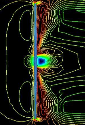
5 for this case. Both models are used with the two-layer all y + wall treatment option which uses the initial cell y + value, from the wall of the wind turbine, to determine if the y + value is in the log layer. If the y + valve is greater than 30, it is assumed that the wall y + value is in the log layer and wall functions are used to satisfy the flow conditions. If the y + values are 1 or less the viscous sublayer is assumed to be resolved and no wall functions are used. VI. Results Histograms of the frequency of the wall cell y + -values are shown in Fig. 6 for the unstructured (polyhedral) mesh and the structured (hexahedral) grid. Relatively large computational domains and the complex geometry cause large variations in the wall cell y + value. This justifies the implementation of the all y + wall treatment available in Star- CCM+ for the selected turbulence models. A study was conducted to determine the effect that unstructured and structured grids have on the simulation results. Vertical profiles of the mean velocity in the streamwise direction are shown in Figs. 7 and 8. There is the separation region close to the turbine hub (Fig.7). The dynamics of mean streamwise velocity profiles with the distance downstream the turbine are given in Fig. 8. In the near wake (x/d < 1), velocity profiles obtained with structured and unstructured grids are in acceptable agreement with each other. A difference between the simulation results obtained using different grids increases with the distance from the turbine. U/2U Figure 7: Mean wake velocity profile behind the turbine at 0.05D. Figure 8: Mean wake velocity profiles at different locations behind the turbine. The hexahedral grid captures the flow geometry much better than the polyhedral grid does at x/d > 1. In simulations with the unstructured mesh, the far wake vanishes fast, which is in contradiction with observations. Figures 9-12 show the velocity and the turbulent kinetic energy contours obtained with the unstructured mesh and the structured grid. These figures give an opportunity to visually compare the simulated wakes behind the turbine. Unphysical results for the far wake are clearly seen when the unstructured mesh is used. Simulation results shown in Figs were obtained with the Menter s turbulence model 4. 10Dx10x10D Polyhedral Figure 9: Mean streamwise velocity contours: unstructured mesh. 5


6 10Dx10Dx10D Figure 10: Mean streamwise velocity contours: structured grid. Polyhedral 10Dx10Dx10D Figure 11: Turbulent kinetic energy contours: unstructured mesh. Hexahedral 10Dx10Dx10D Figure 12: Turbulent kinetic energy: structured grid. Because the simulations conducted with the structured grid produce more realistic results, the structured grids were used in the following simulations. At the next step, the analysis was conducted to determine how the computational domain size affects the simulation results. The Menter s turbulence model 4 was used in simulations. Figure 13 shows the effect that the domain size has on the near-wake vertical profiles of the mean streamwise velocity and the turbulent kinetic energy. The velocity profiles at 1D behind the turbine are in close agreement for different domains. The turbulent kinetic energy profiles although similar, differ in magnitude for different domains. The profiles obtained in the 15Dx10Dx10D domain deviate the most from others. This result is expected as in the longest domain in the streamwise direction, the influence of the outlet boundary conditions on the simulation results should be the least. The mean velocity and turbulent kinetic energy profiles at 5D behind the turbine are shown in Fig. 14. Observations are similar to those made for Fig. 13. That is, the simulation results obtained in the longest domain in the streamwise direction deviate mostly from the profiles obtained in other domains. The wake progression of the mean streamwise velocity component and that of the turbulent kinetic energy are given in Fig
7 The mean streamwise velocity contours obtained in computational domains of different sizes are given in Figs These figures confirm the similarity of the near-wake flow structures obtained in different domains and demonstrate a noticeable difference in the far wake structure when the longest 15Dx10Dx10D domain is used. Figure 13: Vertical profiles of U and k at 1D behind turbine. Figure 14: Vertical profiles of U and k at 5D behind turbine. U/U k (J/kg) Figure 15: Vertical wake profile for U = 6ms -1 7


8 10Dx10Dx10D Figure 16: Mean streamwise velocity contours: 10Dx10Dx10D domain. 15Dx10Dx10D Figure 17: Mean streamwise velocity contours: 15Dx10Dx10D domain. 10Dx15Dx10D Figure 18: Mean streamwise velocity contours: 10Dx15Dx10D domain. 10Dx10Dx15D Figure 19: Mean streamwise velocity contours: 10Dx10Dx15D domain. 8


9 The results presented in Figs are expectedly sensitive to the length of the computational domain in the steamwise direction. They are over-predicted for the mean velocity and the turbulent kinetic energy in shorter domains to compare with the profiles in the longer domain. However, in the absence of accurate observational data to compare the simulation results with, the smallest (and the least computationally expensive) domain, 10Dx10Dx10D, can be used for the analysis of the flow structure in the near wake of the turbine. The reliable far-wake simulations require a larger domain in the streamwise direction. U/U k (J/kg) Figure 20: Velocity and turbulent kinetic energy profiles. k-ω Dx10x10D Figure 21: Contour of mean streamwise velocity using the structured grid for U = 6ms -1 (k-ω 2006) 10Dx10x10D Figure 22: Contour of mean streamwise velocity for U = 6ms -1 10Dx10Dx10D () 9

10 The simulation results obtained with the different turbulence models are compared in Fig. 20. Simulations were conducted with the and k turbulence models 4,5 In the figure, the wake progression is shown. Simulations were conducted in the 10Dx10Dx10D domain. The streamwise velocity profiles are in close agreement with each other in the near wake and differ in magnitude in the far wake. The difference in results is more noticeable in Figures 21 and 22, where the mean streamwise velocity contours obtained with the and k-ω 2006 turbulence models are shown. In Figure 23, vorticity contours obtained with the Menter s turbulence model in the 10Dx10Dx10D domain are presented. Figure 23: Vorticity contours obtained with the model in the 10Dx10Dx10D domain. VII. Conclusions In the paper, the results of the flow simulation around and behind the mid-sized Keuka Rim-Driven Wind Turbine developed by Keuka Energy LLC are present. Simulations were conducted with two RANS turbulence models: and k ,5 turbulence models. A sensitivity analysis of the simulation results to the simulation parameters was conducted. It was demonstrated that the structured grid of hexahedral cells predicts more realistic flow structure in the turbine far wake, than the unstructured mesh with polyhedral cells does. The computational domain size in the streamwise is of importance. Computational profiles are over-predicted in shorter domains even in the near wake of the turbine. Different turbulence models predict the similar growth rate of the turbine wake, but some discrepancies in the predicted flow structure are observed within the wake. Experimental facilities are currently under constructions at the Idaho National Laboratory to obtain the observational data for the RDWT wake. Once the data are available, the simulation results will be validated against them. Acknowledgments Simulations were conducted using the high-performance facilities of the Center for Advanced Research Computing at the University of New Mexico. A part of work was supported by NASA under award NNX12AJ61A and by the Junior Faculty UNM-LANL Collaborative Research Grant. The authors would like to acknowledge support from CD-Adapco for providing STAR CCM+ to the University of New Mexico for academic purposes. References 1 Chen, X., and Ramesh K. Agarwal. "Inclusion of a simple dynamic inflow model in the blade element momentum theory for wind turbine application." International Journal of Energy and Environment, Vol. 5.2, 2014, Rankin, A. J., Poroseva, S. V., and Hovsapian, R. O., Power Curve Data Analysis for Rim Driven Wind Turbine, ASME Early Career Technical Journal, 2011, Vol. 10, pp Sanderse, B., van der Pijl, S. P., and Koren, B., Review of Computational Fluid Dynamics for Wind Turbine Wake Aerodynamics, Wind Energy, 2011, Vol. 14, pp Menter, F. R., "Zonal Two Equation k-omega Turbulence Models for Aerodynamic Flows," AIAA Paper , Wilcox, D.C., Turbulence Modeling for CFD, 3 rd Edition,
11 6 Kaiser, B. E., Poroseva, S. V., Snider, M. A., Hovsapian, R. O., Johnson, E., Flow Simulation Around a Rim-Driven Wind Turbine And In Its Wake, the 58 th ASME Turbo Exposition Proceed., San Antonio, TX, June 3-7, Kaiser, B. E., Poroseva, S. V., Johnson, E., Hovsapian, R. O., Near-Wake Flow Simulations for a Mid-Sized Rim Driven Wind Turbine, AIAA , Proc. the 43th AIAA Fluid Dynamics Conference, San Diego, CA, June 24-27, STAR-CCM+. Ver , CD-Adapco, 9 Snider, M. A., and Poroseva, S. V., Sensitivity Study of Turbulent Flow Simulations Over a Rotating Disk, AIAA , Proc. the 42nd AIAA Fluid Dynamics Conference and Exhibit, New Orleans, June 25-28, Burton, Tony. Wind Energy: Handbook. Chichester: J. Wiley, Chap 1. 11
Sensitivity Study of Turbulent Flow Simulations Over a Rotating Disk
 Sensitivity Study of Turbulent Flow Simulations Over a Rotating Disk Michael A. Snider 1 and Svetlana V. Poroseva 2 University of New Mexico, Albuquerque, New Mexico, 87131 With increasing demand for renewable
McNair Scholars Research Journal
 McNair Scholars Research Journal Volume 2 Article 1 2015 Benchmarking of Computational Models against Experimental Data for Velocity Profile Effects on CFD Analysis of Adiabatic Film-Cooling Effectiveness
Axisymmetric Viscous Flow Modeling for Meridional Flow Calculation in Aerodynamic Design of Half-Ducted Blade Rows
 Memoirs of the Faculty of Engineering, Kyushu University, Vol.67, No.4, December 2007 Axisymmetric Viscous Flow Modeling for Meridional Flow alculation in Aerodynamic Design of Half-Ducted Blade Rows by
Reproducibility of Complex Turbulent Flow Using Commercially-Available CFD Software
 Reports of Research Institute for Applied Mechanics, Kyushu University No.150 (71 83) March 2016 Reproducibility of Complex Turbulent Flow Using Commercially-Available CFD Software Report 3: For the Case
Large Eddy Simulation of Flow over a Backward Facing Step using Fire Dynamics Simulator (FDS)
") The 14 th Asian Congress of Fluid Mechanics - 14ACFM October 15-19, 2013; Hanoi and Halong, Vietnam Large Eddy Simulation of Flow over a Backward Facing Step using Fire Dynamics Simulator (FDS) Md. Mahfuz
The 14 th Asian Congress of Fluid Mechanics - 14ACFM October 15-19, 2013; Hanoi and Halong, Vietnam Large Eddy Simulation of Flow over a Backward Facing Step using Fire Dynamics Simulator (FDS) Md. Mahfuz
Numerische Untersuchungen von Windkraftanlagen: Leistung, Wake und Steuerungsstrategien
 Fachtagung Lasermethoden in der Strömungsmesstechnik 8. 10. September 2015, Dresden Numerische Untersuchungen von Windkraftanlagen: Leistung, Wake und Steuerungsstrategien Numerical Investigations of Wind
THE APPLICATION OF AN ATMOSPHERIC BOUNDARY LAYER TO EVALUATE TRUCK AERODYNAMICS IN CFD
 THE APPLICATION OF AN ATMOSPHERIC BOUNDARY LAYER TO EVALUATE TRUCK AERODYNAMICS IN CFD A SOLUTION FOR A REAL-WORLD ENGINEERING PROBLEM Ir. Niek van Dijk DAF Trucks N.V. CONTENTS Scope & Background Theory:
COMPUTATIONAL FLUID DYNAMICS ANALYSIS OF ORIFICE PLATE METERING SITUATIONS UNDER ABNORMAL CONFIGURATIONS
 COMPUTATIONAL FLUID DYNAMICS ANALYSIS OF ORIFICE PLATE METERING SITUATIONS UNDER ABNORMAL CONFIGURATIONS Dr W. Malalasekera Version 3.0 August 2013 1 COMPUTATIONAL FLUID DYNAMICS ANALYSIS OF ORIFICE PLATE
LES Analysis on Shock-Vortex Ring Interaction
 LES Analysis on Shock-Vortex Ring Interaction Yong Yang Jie Tang Chaoqun Liu Technical Report 2015-08 http://www.uta.edu/math/preprint/ LES Analysis on Shock-Vortex Ring Interaction Yong Yang 1, Jie Tang
3D Modeling of Urban Areas for Built Environment CFD Applications
 3D Modeling of Urban Areas for Built Environment CFD Applications using C A.W.M. (Jos) van Schijndel Eindhoven University of Technology P.O. Box 513; 5600 MB Eindhoven; Netherlands, A.W.M.v.Schijndel@tue.nl
High-Lift Aerodynamics: STAR-CCM+ Applied to AIAA HiLiftWS1 D. Snyder
 High-Lift Aerodynamics: STAR-CCM+ Applied to AIAA HiLiftWS1 D. Snyder Aerospace Application Areas Aerodynamics Subsonic through Hypersonic Aeroacoustics Store release & weapons bay analysis High lift devices
Introduction to ANSYS CFX
 Workshop 03 Fluid flow around the NACA0012 Airfoil 16.0 Release Introduction to ANSYS CFX 2015 ANSYS, Inc. March 13, 2015 1 Release 16.0 Workshop Description: The flow simulated is an external aerodynamics
Simulation of Laminar Pipe Flows
 Simulation of Laminar Pipe Flows 57:020 Mechanics of Fluids and Transport Processes CFD PRELAB 1 By Timur Dogan, Michael Conger, Maysam Mousaviraad, Tao Xing and Fred Stern IIHR-Hydroscience & Engineering
Driven Cavity Example
 BMAppendixI.qxd 11/14/12 6:55 PM Page I-1 I CFD Driven Cavity Example I.1 Problem One of the classic benchmarks in CFD is the driven cavity problem. Consider steady, incompressible, viscous flow in a square
Backward facing step Homework. Department of Fluid Mechanics. For Personal Use. Budapest University of Technology and Economics. Budapest, 2010 autumn
 Backward facing step Homework Department of Fluid Mechanics Budapest University of Technology and Economics Budapest, 2010 autumn Updated: October 26, 2010 CONTENTS i Contents 1 Introduction 1 2 The problem
STAR-CCM+: Wind loading on buildings SPRING 2018
 STAR-CCM+: Wind loading on buildings SPRING 2018 1. Notes on the software 2. Assigned exercise (submission via Blackboard; deadline: Thursday Week 3, 11 pm) 1. NOTES ON THE SOFTWARE STAR-CCM+ generates
NUMERICAL INVESTIGATION OF THE FLOW BEHAVIOR INTO THE INLET GUIDE VANE SYSTEM (IGV)
") University of West Bohemia» Department of Power System Engineering NUMERICAL INVESTIGATION OF THE FLOW BEHAVIOR INTO THE INLET GUIDE VANE SYSTEM (IGV) Publication was supported by project: Budování excelentního
University of West Bohemia» Department of Power System Engineering NUMERICAL INVESTIGATION OF THE FLOW BEHAVIOR INTO THE INLET GUIDE VANE SYSTEM (IGV) Publication was supported by project: Budování excelentního
Reproducibility of Complex Turbulent Flow Using Commercially-Available CFD Software
 Reports of Research Institute for Applied Mechanics, Kyushu University, No.150 (60-70) March 2016 Reproducibility of Complex Turbulent Flow Using Commercially-Available CFD Software Report 2: For the Case
Transition Flow and Aeroacoustic Analysis of NACA0018 Satish Kumar B, Fred Mendonç a, Ghuiyeon Kim, Hogeon Kim
 Transition Flow and Aeroacoustic Analysis of NACA0018 Satish Kumar B, Fred Mendonç a, Ghuiyeon Kim, Hogeon Kim Transition Flow and Aeroacoustic Analysis of NACA0018 Satish Kumar B, Fred Mendonç a, Ghuiyeon
Coupling of STAR-CCM+ to Other Theoretical or Numerical Solutions. Milovan Perić
 Coupling of STAR-CCM+ to Other Theoretical or Numerical Solutions Milovan Perić Contents The need to couple STAR-CCM+ with other theoretical or numerical solutions Coupling approaches: surface and volume
MOMENTUM AND HEAT TRANSPORT INSIDE AND AROUND
 MOMENTUM AND HEAT TRANSPORT INSIDE AND AROUND A CYLINDRICAL CAVITY IN CROSS FLOW G. LYDON 1 & H. STAPOUNTZIS 2 1 Informatics Research Unit for Sustainable Engrg., Dept. of Civil Engrg., Univ. College Cork,
Turbulence Modeling. Gilles Eggenspieler, Ph.D. Senior Product Manager
 Turbulence Modeling Gilles Eggenspieler, Ph.D. Senior Product Manager 1 Overview The Role of Steady State (RANS) Turbulence Modeling Overview of Reynolds-Averaged Navier Stokes (RANS) Modeling Capabilities
Simulation of Flow Development in a Pipe
 Tutorial 4. Simulation of Flow Development in a Pipe Introduction The purpose of this tutorial is to illustrate the setup and solution of a 3D turbulent fluid flow in a pipe. The pipe networks are common
Modeling External Compressible Flow
 Tutorial 3. Modeling External Compressible Flow Introduction The purpose of this tutorial is to compute the turbulent flow past a transonic airfoil at a nonzero angle of attack. You will use the Spalart-Allmaras
Reproducibility of Complex Turbulent Flow Using Commercially-Available CFD Software
 Reports of Research Institute for Applied Mechanics, Kyushu University No.150 (47 59) March 2016 Reproducibility of Complex Turbulent Using Commercially-Available CFD Software Report 1: For the Case of
ANSYS FLUENT. Airfoil Analysis and Tutorial
 ANSYS FLUENT Airfoil Analysis and Tutorial ENGR083: Fluid Mechanics II Terry Yu 5/11/2017 Abstract The NACA 0012 airfoil was one of the earliest airfoils created. Its mathematically simple shape and age
Numerical Simulation Study on Aerodynamic Characteristics of the High Speed Train under Crosswind
 2017 2nd International Conference on Industrial Aerodynamics (ICIA 2017) ISBN: 978-1-60595-481-3 Numerical Simulation Study on Aerodynamic Characteristics of the High Speed Train under Crosswind Fan Zhao,
Effect of Position of Wall Mounted Surface Protrusion in Drag Characteristics At Low Reynolds Number
 ISSN (e): 2250 3005 Volume, 07 Issue, 11 November 2017 International Journal of Computational Engineering Research (IJCER) Effect of Position of Wall Mounted Surface Protrusion in Drag Characteristics
Application of Wray-Agarwal Turbulence Model for Accurate Numerical Simulation of Flow Past a Three-Dimensional Wing-body
 Washington University in St. Louis Washington University Open Scholarship Mechanical Engineering and Materials Science Independent Study Mechanical Engineering & Materials Science 4-28-2016 Application
Verification and Validation of Turbulent Flow around a Clark-Y Airfoil
 Verification and Validation of Turbulent Flow around a Clark-Y Airfoil 1. Purpose 58:160 Intermediate Mechanics of Fluids CFD LAB 2 By Tao Xing and Fred Stern IIHR-Hydroscience & Engineering The University
COMPUTATIONAL MODELING OF WIND ENERGY SYSTEMS
 The Eighth Asia-Pacific Conference on Wind Engineering, December 10 14, 2013, Chennai, India COMPUTATIONAL MODELING OF WIND ENERGY SYSTEMS T. Shah 1, R. Prasad 2 and M. Damodaran 3 1 Project Associate,
Verification of Laminar and Validation of Turbulent Pipe Flows
 1 Verification of Laminar and Validation of Turbulent Pipe Flows 1. Purpose ME:5160 Intermediate Mechanics of Fluids CFD LAB 1 (ANSYS 18.1; Last Updated: Aug. 1, 2017) By Timur Dogan, Michael Conger, Dong-Hwan
Numerical Study of Turbulent Flow over Backward-Facing Step with Different Turbulence Models
 Numerical Study of Turbulent Flow over Backward-Facing Step with Different Turbulence Models D. G. Jehad *,a, G. A. Hashim b, A. K. Zarzoor c and C. S. Nor Azwadi d Department of Thermo-Fluids, Faculty
MESHLESS SOLUTION OF INCOMPRESSIBLE FLOW OVER BACKWARD-FACING STEP
 Vol. 12, Issue 1/2016, 63-68 DOI: 10.1515/cee-2016-0009 MESHLESS SOLUTION OF INCOMPRESSIBLE FLOW OVER BACKWARD-FACING STEP Juraj MUŽÍK 1,* 1 Department of Geotechnics, Faculty of Civil Engineering, University
NUMERICAL 3D TRANSONIC FLOW SIMULATION OVER A WING
 Review of the Air Force Academy No.3 (35)/2017 NUMERICAL 3D TRANSONIC FLOW SIMULATION OVER A WING Cvetelina VELKOVA Department of Technical Mechanics, Naval Academy Nikola Vaptsarov,Varna, Bulgaria (cvetelina.velkova1985@gmail.com)
CFD SIMULATIONS OF HORIZONTAL AXIS WIND TURBINE (HAWT) BLADES FOR VARIATION WITH WIND SPEED
 BLADES FOR VARIATION WITH WIND SPEED") 2 nd National Conference on CFD Applications in Power and Industry Sectors January 28-29, 2009, Hydrabad, India CFD SIMULATIONS OF HORIZONTAL AXIS WIND TURBINE (HAWT) BLADES FOR VARIATION WITH WIND SPEED
2 nd National Conference on CFD Applications in Power and Industry Sectors January 28-29, 2009, Hydrabad, India CFD SIMULATIONS OF HORIZONTAL AXIS WIND TURBINE (HAWT) BLADES FOR VARIATION WITH WIND SPEED
Introduction to CFX. Workshop 2. Transonic Flow Over a NACA 0012 Airfoil. WS2-1. ANSYS, Inc. Proprietary 2009 ANSYS, Inc. All rights reserved.
 Workshop 2 Transonic Flow Over a NACA 0012 Airfoil. Introduction to CFX WS2-1 Goals The purpose of this tutorial is to introduce the user to modelling flow in high speed external aerodynamic applications.
NUMERICAL SIMULATION OF FLOW FIELD IN AN ANNULAR TURBINE STATOR WITH FILM COOLING
 24 TH INTERNATIONAL CONGRESS OF THE AERONAUTICAL SCIENCES NUMERICAL SIMULATION OF FLOW FIELD IN AN ANNULAR TURBINE STATOR WITH FILM COOLING Jun Zeng *, Bin Wang *, Yong Kang ** * China Gas Turbine Establishment,
Numerical calculation of the wind action on buildings using Eurocode 1 atmospheric boundary layer velocity profiles
 Numerical calculation of the wind action on buildings using Eurocode 1 atmospheric boundary layer velocity profiles M. F. P. Lopes IDMEC, Instituto Superior Técnico, Av. Rovisco Pais 149-1, Lisboa, Portugal
CFD wake modeling using a porous disc
 CFD wake modeling using a porous disc Giorgio Crasto, Arne Reidar Gravdahl giorgio@windsim.com, arne@windsim.com WindSim AS Fjordgaten 5 N-325 Tønsberg Norway Tel. +47 33 38 8 Fax +47 33 38 8 8 http://www.windsim.com
Lab 8: FLUENT: Turbulent Boundary Layer Flow with Convection
 Lab 8: FLUENT: Turbulent Boundary Layer Flow with Convection Objective: The objective of this laboratory is to use FLUENT to solve for the total drag and heat transfer rate for external, turbulent boundary
Estimating Vertical Drag on Helicopter Fuselage during Hovering
 Estimating Vertical Drag on Helicopter Fuselage during Hovering A. A. Wahab * and M.Hafiz Ismail ** Aeronautical & Automotive Dept., Faculty of Mechanical Engineering, Universiti Teknologi Malaysia, 81310
Detached-Eddy Simulation of a Linear Compressor Cascade with Tip Gap and Moving Wall *)
") FOI, Stockholm, Sweden 14-15 July, 2005 Detached-Eddy Simulation of a Linear Compressor Cascade with Tip Gap and Moving Wall *) A. Garbaruk,, M. Shur, M. Strelets, and A. Travin *) Study is carried out
FOI, Stockholm, Sweden 14-15 July, 2005 Detached-Eddy Simulation of a Linear Compressor Cascade with Tip Gap and Moving Wall *) A. Garbaruk,, M. Shur, M. Strelets, and A. Travin *) Study is carried out
A Comparison of RANS-Based Turbulence Modeling for Flow over a Wall-Mounted Square Cylinder
 A Comparison of RANS-Based Turbulence Modeling for Flow over a Wall-Mounted Square Cylinder P. L. Davis 1, A. T. Rinehimer 2, and M.Uddin 3 N C Motorsports and Automotive Research Center, Department of
Application of STAR-CCM+ to Helicopter Rotors in Hover
 Application of STAR-CCM+ to Helicopter Rotors in Hover Lakshmi N. Sankar and Chong Zhou School of Aerospace Engineering, Georgia Institute of Technology, Atlanta, GA Ritu Marpu Eschol CD-Adapco, Inc.,
Potsdam Propeller Test Case (PPTC)
") Second International Symposium on Marine Propulsors smp 11, Hamburg, Germany, June 2011 Workshop: Propeller performance Potsdam Propeller Test Case (PPTC) Olof Klerebrant Klasson 1, Tobias Huuva 2 1 Core
Second International Symposium on Marine Propulsors smp 11, Hamburg, Germany, June 2011 Workshop: Propeller performance Potsdam Propeller Test Case (PPTC) Olof Klerebrant Klasson 1, Tobias Huuva 2 1 Core
MASSACHUSETTS INSTITUTE OF TECHNOLOGY. Analyzing wind flow around the square plate using ADINA Project. Ankur Bajoria
 MASSACHUSETTS INSTITUTE OF TECHNOLOGY Analyzing wind flow around the square plate using ADINA 2.094 - Project Ankur Bajoria May 1, 2008 Acknowledgement I would like to thank ADINA R & D, Inc for the full
S-ducts and Nozzles: STAR-CCM+ at the Propulsion Aerodynamics Workshop. Peter Burns, CD-adapco
 S-ducts and Nozzles: STAR-CCM+ at the Propulsion Aerodynamics Workshop Peter Burns, CD-adapco Background The Propulsion Aerodynamics Workshop (PAW) has been held twice PAW01: 2012 at the 48 th AIAA JPC
WALL Y + APPROACH FOR DEALING WITH TURBULENT FLOW OVER A SURFACE MOUNTED CUBE: PART 2 HIGH REYNOLDS NUMBER
 Seventh International Conference on CFD in the Minerals and Process Industries CSIRO, Melbourne, Australia 9- December 9 WALL Y + APPROACH FOR DEALING WITH TURBULENT FLOW OVER A SURFACE MOUNTED CUBE: PART
Simulation and Validation of Turbulent Pipe Flows
 Simulation and Validation of Turbulent Pipe Flows ENGR:2510 Mechanics of Fluids and Transport Processes CFD LAB 1 (ANSYS 17.1; Last Updated: Oct. 10, 2016) By Timur Dogan, Michael Conger, Dong-Hwan Kim,
Using a Single Rotating Reference Frame
 Tutorial 9. Using a Single Rotating Reference Frame Introduction This tutorial considers the flow within a 2D, axisymmetric, co-rotating disk cavity system. Understanding the behavior of such flows is
CFD MODELING FOR PNEUMATIC CONVEYING
 CFD MODELING FOR PNEUMATIC CONVEYING Arvind Kumar 1, D.R. Kaushal 2, Navneet Kumar 3 1 Associate Professor YMCAUST, Faridabad 2 Associate Professor, IIT, Delhi 3 Research Scholar IIT, Delhi e-mail: arvindeem@yahoo.co.in
CFD Analysis of a Fully Developed Turbulent Flow in a Pipe with a Constriction and an Obstacle
 CFD Analysis of a Fully Developed Turbulent Flow in a Pipe with a Constriction and an Obstacle C, Diyoke Mechanical Engineering Department Enugu State University of Science & Tech. Enugu, Nigeria U, Ngwaka
CFD Analysis of 2-D Unsteady Flow Past a Square Cylinder at an Angle of Incidence
 CFD Analysis of 2-D Unsteady Flow Past a Square Cylinder at an Angle of Incidence Kavya H.P, Banjara Kotresha 2, Kishan Naik 3 Dept. of Studies in Mechanical Engineering, University BDT College of Engineering,
Simulation of Turbulent Flow over the Ahmed Body
 Simulation of Turbulent Flow over the Ahmed Body 58:160 Intermediate Mechanics of Fluids CFD LAB 4 By Timur K. Dogan, Michael Conger, Maysam Mousaviraad, and Fred Stern IIHR-Hydroscience & Engineering
Computational Simulation of the Wind-force on Metal Meshes
 16 th Australasian Fluid Mechanics Conference Crown Plaza, Gold Coast, Australia 2-7 December 2007 Computational Simulation of the Wind-force on Metal Meshes Ahmad Sharifian & David R. Buttsworth Faculty
Non-Newtonian Transitional Flow in an Eccentric Annulus
 Tutorial 8. Non-Newtonian Transitional Flow in an Eccentric Annulus Introduction The purpose of this tutorial is to illustrate the setup and solution of a 3D, turbulent flow of a non-newtonian fluid. Turbulent
Tutorial 2. Modeling Periodic Flow and Heat Transfer
 Tutorial 2. Modeling Periodic Flow and Heat Transfer Introduction: Many industrial applications, such as steam generation in a boiler or air cooling in the coil of an air conditioner, can be modeled as
Research and Design working characteristics of orthogonal turbine Nguyen Quoc Tuan (1), Chu Dinh Do (2), Quach Thi Son (2)
, Chu Dinh Do (2), Quach Thi Son (2)") GSJ: VOLUME 6, ISSUE 6, JUNE 018 116 Research and Design working characteristics of orthogonal turbine Nguyen Quoc Tuan (1), Chu Dinh Do (), Quach Thi Son () (1) Institute for hydro power and renewable
GSJ: VOLUME 6, ISSUE 6, JUNE 018 116 Research and Design working characteristics of orthogonal turbine Nguyen Quoc Tuan (1), Chu Dinh Do (), Quach Thi Son () (1) Institute for hydro power and renewable
Direct Numerical Simulation of a Low Pressure Turbine Cascade. Christoph Müller
 Low Pressure NOFUN 2015, Braunschweig, Overview PostProcessing Experimental test facility Grid generation Inflow turbulence Conclusion and slide 2 / 16 Project Scale resolving Simulations give insight
Keywords: flows past a cylinder; detached-eddy-simulations; Spalart-Allmaras model; flow visualizations
 A TURBOLENT FLOW PAST A CYLINDER *Vít HONZEJK, **Karel FRAŇA *Technical University of Liberec Studentská 2, 461 17, Liberec, Czech Republic Phone:+ 420 485 353434 Email: vit.honzejk@seznam.cz **Technical
Large Eddy Simulation of Turbulent Flow Past a Bluff Body using OpenFOAM
 Large Eddy Simulation of Turbulent Flow Past a Bluff Body using OpenFOAM A Thesis Presented By David Joseph Hensel To The Department of Mechanical and Industrial Engineering in partial fulfillment of the
CFD VALIDATION FOR SURFACE COMBATANT 5415 STRAIGHT AHEAD AND STATIC DRIFT 20 DEGREE CONDITIONS USING STAR CCM+
 CFD VALIDATION FOR SURFACE COMBATANT 5415 STRAIGHT AHEAD AND STATIC DRIFT 20 DEGREE CONDITIONS USING STAR CCM+ by G. J. Grigoropoulos and I..S. Kefallinou 1. Introduction and setup 1. 1 Introduction The
Keywords: CFD, aerofoil, URANS modeling, flapping, reciprocating movement
 L.I. Garipova *, A.N. Kusyumov *, G. Barakos ** * Kazan National Research Technical University n.a. A.N.Tupolev, ** School of Engineering - The University of Liverpool Keywords: CFD, aerofoil, URANS modeling,
Dimensioning and Airflow Simulation of the Wing of an Ultralight Aircraft
 Dimensioning and Airflow Simulation of the Wing of an Ultralight Aircraft Richárd Molnár 1 Gergely Dezső 2* Abstract: Increasing interest to ultralight aircrafts usually made of composite materials leads
Possibility of Implicit LES for Two-Dimensional Incompressible Lid-Driven Cavity Flow Based on COMSOL Multiphysics
 Possibility of Implicit LES for Two-Dimensional Incompressible Lid-Driven Cavity Flow Based on COMSOL Multiphysics Masanori Hashiguchi 1 1 Keisoku Engineering System Co., Ltd. 1-9-5 Uchikanda, Chiyoda-ku,
RANS COMPUTATION OF RIBBED DUCT FLOW USING FLUENT AND COMPARING TO LES
 RANS COMPUTATION OF RIBBED DUCT FLOW USING FLUENT AND COMPARING TO LES Máté M., Lohász +*& / Ákos Csécs + + Department of Fluid Mechanics, Budapest University of Technology and Economics, Budapest * Von
CFD design tool for industrial applications
 Sixth LACCEI International Latin American and Caribbean Conference for Engineering and Technology (LACCEI 2008) Partnering to Success: Engineering, Education, Research and Development June 4 June 6 2008,
A Comparative CFD Analysis of a Journal Bearing with a Microgroove on the Shaft & Journal
 Proceedings of International Conference on Innovation & Research in Technology for Sustainable Development (ICIRT 2012), 01-03 November 2012 182 A Comparative CFD Analysis of a Journal Bearing with a Microgroove
Comparison of CFD Simulation of a Hyundai I20 Model with Four Different Turbulence Models
 RESEARCH ARTICLE OPEN ACCESS Comparison of CFD Simulation of a Hyundai I20 with Four Different Turbulence s M. Vivekanandan*, R. Sivakumar**, Aashis. S. Roy*** *(Uttam Industrial Engg. Pvt. Ltd., Tiruchirapalli,
Detached Eddy Simulation Analysis of a Transonic Rocket Booster for Steady & Unsteady Buffet Loads
 Detached Eddy Simulation Analysis of a Transonic Rocket Booster for Steady & Unsteady Buffet Loads Matt Knapp Chief Aerodynamicist TLG Aerospace, LLC Presentation Overview Introduction to TLG Aerospace
CFD Study of a Darreous Vertical Axis Wind Turbine
 CFD Study of a Darreous Vertical Axis Wind Turbine Md Nahid Pervez a and Wael Mokhtar b a Graduate Assistant b PhD. Assistant Professor Grand Valley State University, Grand Rapids, MI 49504 E-mail:, mokhtarw@gvsu.edu
SIMULATION OF FLOW FIELD AROUND AND INSIDE SCOUR PROTECTION WITH PHYSICAL AND REALISTIC PARTICLE CONFIGURATIONS
 XIX International Conference on Water Resources CMWR 2012 University of Illinois at Urbana-Champaign June 17-22, 2012 SIMULATION OF FLOW FIELD AROUND AND INSIDE SCOUR PROTECTION WITH PHYSICAL AND REALISTIC
Stream Function-Vorticity CFD Solver MAE 6263
 Stream Function-Vorticity CFD Solver MAE 66 Charles O Neill April, 00 Abstract A finite difference CFD solver was developed for transient, two-dimensional Cartesian viscous flows. Flow parameters are solved
PUBLISHED VERSION. Originally Published at: PERMISSIONS. 23 August 2015
 PUBLISHED VERSION Yinli Liu, Hao Tang, Zhaofeng Tian, Haifei Zheng CFD simulations of turbulent flows in a twin swirl combustor by RANS and hybrid RANS/LES methods Energy Procedia, 2015 / Jiang, X., Joyce,
Integration of an unsteady nonlinear lifting line free wake algorithm in a wind turbine design framework
 Integration of an unsteady nonlinear lifting line free wake algorithm in a wind turbine design framework Introduction D. Marten, G. Pechlivanoglou, C. N. Nayeri, C. O. Paschereit TU Berlin, Institute of
A B C D E. Settings Choose height, H, free stream velocity, U, and fluid (dynamic viscosity and density ) so that: Reynolds number
 so that: Reynolds number") Individual task Objective To derive the drag coefficient for a 2D object, defined as where D (N/m) is the aerodynamic drag force (per unit length in the third direction) acting on the object. The object
Individual task Objective To derive the drag coefficient for a 2D object, defined as where D (N/m) is the aerodynamic drag force (per unit length in the third direction) acting on the object. The object
Prediction of Turbo Compressor Maps using CFD
 Prediction of Turbo Compressor Maps using CFD Master s thesis in Applied Mechanics STEPHANIE BERGQVIST Department of Applied Mechanics Division of Fluid Dynamics CHALMERS UNIVERSITY OF TECHNOLOGY Gothenburg,
Numerical and theoretical analysis of shock waves interaction and reflection
 Fluid Structure Interaction and Moving Boundary Problems IV 299 Numerical and theoretical analysis of shock waves interaction and reflection K. Alhussan Space Research Institute, King Abdulaziz City for
This tutorial illustrates how to set up and solve a problem involving solidification. This tutorial will demonstrate how to do the following:
 Tutorial 22. Modeling Solidification Introduction This tutorial illustrates how to set up and solve a problem involving solidification. This tutorial will demonstrate how to do the following: Define a
SIMULATION OF PROPELLER-SHIP HULL INTERACTION USING AN INTEGRATED VLM/RANSE SOLVER MODELING.
 SIMULATION OF PROPELLER-SHIP HULL INTERACTION USING AN INTEGRATED VLM/RANSE SOLVER MODELING. M.N.Senthil Prakash, Department of Ocean Engineering, IIT Madras, India V. Anantha Subramanian Department of
Estimation of Flow Field & Drag for Aerofoil Wing
 Estimation of Flow Field & Drag for Aerofoil Wing Mahantesh. HM 1, Prof. Anand. SN 2 P.G. Student, Dept. of Mechanical Engineering, East Point College of Engineering, Bangalore, Karnataka, India 1 Associate
Profile Catalogue for Airfoil Sections Based on 3D Computations
 Risø-R-58(EN) Profile Catalogue for Airfoil Sections Based on 3D Computations Franck Bertagnolio, Niels N. Sørensen and Jeppe Johansen Risø National Laboratory Roskilde Denmark December 26 Author: Franck
Simulation of Turbulent Flow in an Asymmetric Diffuser
 Simulation of Turbulent Flow in an Asymmetric Diffuser 1. Purpose 58:160 Intermediate Mechanics of Fluids CFD LAB 3 By Tao Xing and Fred Stern IIHR-Hydroscience & Engineering The University of Iowa C.
CFD modelling of thickened tailings Final project report
 26.11.2018 RESEM Remote sensing supporting surveillance and operation of mines CFD modelling of thickened tailings Final project report Lic.Sc.(Tech.) Reeta Tolonen and Docent Esa Muurinen University of
Simulation of a Free Surface Flow over a Container Vessel Using CFD
 Simulation of a Free Surface Flow over a Container Vessel Using CFD Krishna Atreyapurapu 1 Bhanuprakash Tallapragada 2 Kiran Voonna 3 M.E Student Professor Manager Dept. of Marine Engineering Dept. of
ICMIEE D CFD Analysis of a Straight-bladed Vertical Axis Wind Turbine Using General Grid Interface Method
 International Conference on Mechanical, Industrial and Energy Engineering 2018 23-24 December, 2018, Khulna, BANGLADESH ICMIEE18-319 2D CFD Analysis of a Straight-bladed Vertical Axis Wind Turbine Using
Simulations of the vortex in the Dellenback abrupt expansion, resembling a hydro turbine draft tube operating at part-load
 Simulations of the vortex in the Dellenback abrupt expansion, resembling a hydro turbine draft tube operating at part-load H Nilsson Chalmers University of Technology, SE-412 96 Gothenburg, Sweden E-mail:
CFD Post-Processing of Rampressor Rotor Compressor
 Gas Turbine Industrial Fellowship Program 2006 CFD Post-Processing of Rampressor Rotor Compressor Curtis Memory, Brigham Young niversity Ramgen Power Systems Mentor: Rob Steele I. Introduction Recent movements
Express Introductory Training in ANSYS Fluent Workshop 04 Fluid Flow Around the NACA0012 Airfoil
 Express Introductory Training in ANSYS Fluent Workshop 04 Fluid Flow Around the NACA0012 Airfoil Dimitrios Sofialidis Technical Manager, SimTec Ltd. Mechanical Engineer, PhD PRACE Autumn School 2013 -
Validation of a Multi-physics Simulation Approach for Insertion Electromagnetic Flowmeter Design Application
 Validation of a Multi-physics Simulation Approach for Insertion Electromagnetic Flowmeter Design Application Setup Numerical Turbulence ing by March 15, 2015 Markets Insertion electromagnetic flowmeters
ON THE NUMERICAL MODELING OF IMPINGING JET HEAT TRANSFER
 ON THE NUMERICAL MODELING OF IMPINGING JET HEAT TRANSFER Mirko Bovo 1,2, Sassan Etemad 2 and Lars Davidson 1 1 Dept. of Applied Mechanics, Chalmers University of Technology, Gothenburg, Sweden 2 Powertrain
ANSYS AIM Tutorial Turbulent Flow Over a Backward Facing Step
 ANSYS AIM Tutorial Turbulent Flow Over a Backward Facing Step Author(s): Sebastian Vecchi, ANSYS Created using ANSYS AIM 18.1 Problem Specification Pre-Analysis & Start Up Governing Equation Start-Up Geometry
A PARABOLIZED NAVIER STOKES METHOD FOR WIND FARM APPLICATIONS. Anshul Mittal. Engineering
 A PARABOLIZED NAVIER STOKES METHOD FOR WIND FARM APPLICATIONS By Anshul Mittal Lafayette K. Taylor Professor (Retired) of Computational Engineering Committee Chair W. Roger Briley Professor Emeritus of
Effects of bell mouth geometries on the flow rate of centrifugal blowers
 Journal of Mechanical Science and Technology 25 (9) (2011) 2267~2276 www.springerlink.com/content/1738-494x DOI 10.1007/s12206-011-0609-3 Effects of bell mouth geometries on the flow rate of centrifugal
Offshore Platform Fluid Structure Interaction (FSI) Simulation
 Simulation") Offshore Platform Fluid Structure Interaction (FSI) Simulation Ali Marzaban, CD-adapco Murthy Lakshmiraju, CD-adapco Nigel Richardson, CD-adapco Mike Henneke, CD-adapco Guangyu Wu, Chevron Pedro M. Vargas,
Offshore Platform Fluid Structure Interaction (FSI) Simulation Ali Marzaban, CD-adapco Murthy Lakshmiraju, CD-adapco Nigel Richardson, CD-adapco Mike Henneke, CD-adapco Guangyu Wu, Chevron Pedro M. Vargas,
Drag and Lift Validation of Wing Profiles
 Drag and Lift Validation of Wing Profiles STAR European Conference 2010 London By: Dr Martin van Staden Aerotherm Computational Dynamics 14th IAHR Conference December 2009 Outline of Presentation Background
EVALUATION OF A GENERAL CFD-SOLVER FOR A MICRO-SCALE URBAN FLOW
 EVALATION OF A GENERAL CFD-SOLVER FOR A MICRO-SCALE RBAN FLOW Jarkko Saloranta and Antti Hellsten Helsinki niversity of Technology, Laboratory of Aerodynamics, Finland INTRODCTION In this work we study
DYNAMICS OF A VORTEX RING AROUND A MAIN ROTOR HELICOPTER
 DYNAMICS OF A VORTEX RING AROUND A MAIN ROTOR HELICOPTER Katarzyna Surmacz Instytut Lotnictwa Keywords: VORTEX RING STATE, HELICOPTER DESCENT, NUMERICAL ANALYSIS, FLOW VISUALIZATION Abstract The main goal
02_CRADLE 03_CSSRC 04_HSVA
 A Computational Domain Domain Topology A1 1 steady domain 1 rotating domain Multiple domains Grid coupling technique A2 Sliding Overset Multiple ref. Frames B Propeller Representation Resolution B1 Geometrically