E21 Operation Manual. (Version: V1.04)
|
|
|
- Megan Katherine Pope
- 5 years ago
- Views:
Transcription
")

1 (Version: V1.04)
2 Contents Preface... 1 Chapter 1 Product Overview Product introduction Operation panel Displayer... 4 Chapter 2 Operation Instruction Basic operation procedure Programming Single-step programming Multi-step programming Parameter setting Manual movement Chapter 3 Alarm Appendix Common fault and troubleshooting... 18
3 Preface This manual describes operation of E21 numerical control device and is meant for operators who are instructed for operation of the device. Operator shall read through this manual and know operation requirements before using this device. Copy right is preserved by ESTUN. It is not allowed to add or delete part or all of the manual content without ESTUN s consent. Do not use part or all of manual content for the third party s design. E21 device provides complete software control and has no mechanical protection device for operator or the tool machine. Therefore, in case of malfunction, machine tool must provide protection device for operator and external part of the machine tool. ESTUN is not responsible for any direct or indirect losses caused by normal or abnormal operation of the device. ESTUN preserves the right to modifying this manual in the event of function adding or print error. 1

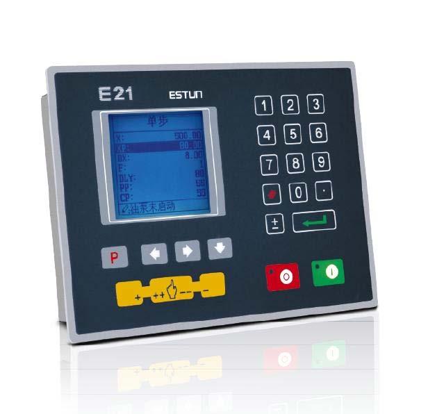
4 1.1 Product introduction Chapter 1 Product Overview This product is equipped with press brake machine dedicated numerical control device which is applicable to various users. On the basis of ensuring work precision, the cost of numerical control bending machine is reduced significantly. Features of this product are listed below: Positioning control of back gauge. Intelligent positioning control. Unilateral and bidirectional positioning which eliminates spindle clearance effectively. Retract functions. Automatic reference searching. One-key parameter backup and restore. Fast position indexing. 40 programs storage space, each program has 25 steps. Power-off protection. 1.2 Operation panel Operation panel is shown in Figure 1-1. Figure 1-1 Operation panel Functions of panel keys are described in Table
5 Table 1-1 Description of key functions Key Function description Delete key: delete all data in input area on left bottom of displayer. Enter key: confirm the input content. If no content is input, the key has the similar function to direction key. Start key: automatic start-up, top left corner of the key is operation indicator LED. When operation is started, this indicator LED is on. Stop key: stop operation, top left corner of the key is Stop indicator LED. When initialize normal start-up and no operation, this indicator LED is on. Left direction key: page forward, cursor remove Right direction key: page backward, cursor remove Down direction key: select parameter downward Function switch: switch over different function pages Symbolic key: user input symbol, or start diagnosis. ~ Numeric key: when setting parameter, input value. Decimal point key: when set up parameter, input decimal point. Manual movement key: in case of manual adjustment, make adjustment object move in forward direction at low speed. Manual movement key: in case of manual adjustment, make adjustment object move in backward direction at low speed. High speed selection key: in case of manual adjustment, press this key and press simultaneously, make adjustment object move in increasing direction at high speed, then press decreasing direction at high speed., make adjustment object move in 3
6 1.3 Displayer E21 numerical control device adopts 160*160 dot matrix LCD displayer. The display area is shown in Figure 1-2. Title bar Parameter display area Status bar Single X: Y: Xp: Yp: Dx: Dd: 1000 PP: 1000 Dly: 1000 CP: 1000 Range:0~ mm Figure 1-2 Display area Title bar: display relevant information of current page, such as its name, etc. Parameter display area: display parameter name, parameter value and system information. Status bar: display area of input information and prompt message, etc. 4
7 Chapter 2 Operation Instruction 2.1 Basic operation procedure Basic switch over and operation procedure of the device is shown in Figure 2-1. START Press Single-Step Manual RUN P Press Press l Press P Press P Press l PROGRAMS Mutil-Step RUN Press Press CONST P Password: Password: 5656 System parameter DIAGNOSE Press Press P ALARM Figure 2-1 Basic Operational Flow 5
8 2.2 Programming The device has two programming methods, which are single-step programming and multi-step programming. User can set up programming according to actual demand Single-step programming When the parameter X or Y displays ******** on the page, please do not enter the RUN page or Manual page, unless you have reset the teach function of X-axis or Y-axis. Single-step programming is generally used for processing single step to finish work piece processing. When controller is power on, it will automatically enter single-step program page. Operation steps Step 1 After starting up, the device will enter setting up page of single-step program automatically, as shown in Figure 2-2. Single X: Y: XP: YP: DX: HT: 1000 PP: 100 DLY: 1000 CP: 100 Range: Between soft lim. Figure 2-2 Single-step program setting page Step 2 Press, select parameter which needs to be set up, press numerical key to input program value, press to complete input. [Note] Parameter can only be set when Stop indicator is on. Setting range of singe step parameter is shown in Table
9 Table 2-1 Set up range of singe step parameter Parameter name Unit Set up range Remarks X mm/inch - Current position of X axis, unable to be modified. Y mm/inch - Current position of Y axis, unable to be modified. XP mm/inch 0~ Program position of X axis. YP mm/inch 0~ Target position of Y axis. DX mm/inch 0~ Retract distance of X axis. HT s 0~99.99 The time between concession signal valid and end hold time output. DLY s 0~99.99 In case of single step, delay time for X axis concession. PP - 0~9999 Number of preset work piece. CP - 0~9999 Number of current work piece. Step 3 Press 2-3., system will execute according to this program, as shown in Figure Single X: Y: C: 0 PP: 0 mm Figure 2-3 Single step operation page Operation example On single-step program page, program bending depth to 100.0mm, back gauge position to 80.00mm, retract distance to 50mm, concession waiting time to 2s, holding time to 3s, work piece to 10. Operation steps are shown in Table
10 Table 2-2 Operation steps of single step example Operation steps Operation Step 1 Press, select XP parameter. Step 2 Input by numerical key. Step 3 Press, confirm setting of this parameter. Step 4 Press, select YP parameter. Step 5 Input by numerical key. Step 6 Press, confirm set up of this parameter. Step 9 Press, select DX parameter, DLY parameter, HT parameter, PP parameter respectively. Step 10 Set up parameter to 50mm, 2s, 3s, 10, 0 by numerical key. Step 11 Press, system execute according to this program Multi-step programming When the parameter X or Y displays ******** on the page, please do not enter the RUN page, unless you have reset the teach function of X-axis or Y-axis. Multi-step program is used for processing single work piece of different processing steps, realize consecutive implementation of multi-steps, and improve processing efficiency. Operation step Step 1 Power on, the device displays the single-step parameter page automatically. Step 2 Press, switch to program manage page, as shown in Figure 2-4. PROGRAMS 0P program 1ST Figure 2-4 Program management page 8
11 Step 3 Press directly, such as input 1., select program serial number, or input program number Step 4 Press, enter multi-step program setting page, as shown in Figure 2-5. PROGRAM1 ST: 1 PP: 99 CP: 9 DLY: 100 HT: 0 Range:0~25 Figure 2-5 Multi-step program setting page Step 5 Press, select multi-step programming parameter which requires set up, input setting up value, press, and the set up takes effect. Step 6 In completion of set up, press Figure 2-6., enter step parameter set page, as shown in PROGRAM1 1/ 5ST X: Y: XP: YP: DX: RP: 54 Range: Between soft lim. Figure 2-6 Step parameter set page Step 7 Press press Step 8 Press press, select step parameter that needs to be set up, input program value,, and the setup takes effect. to switch over between steps. If the current step is the first step, to enter the last page of step parameter setting; if the current step is the last one, press to enter the first page of step parameter setting. Multi-step parameter setting range is shown in Table
12 Table 2-3 Multi-step parameter setting range Parameter name Unit Setting range Remarks Step number of program - 0~25 Set up total processing step number of this program Preset work piece number - 0~9999 Number of work piece to be processed, decreasing piece when more than zero; negative increasing count. Current work piece number - 0~9999 Number of finished work piece Concession delay s 0~99.99 Time between retract signal and concession execution. Holding time delay s 0~99.99 Time between concession signal and end pressurize output X mm/inch - Current position of X axis, can t be modified; Y mm/inch - Current position of Y axis, can t be modified; X target position mm/inch 0~ Program position of X axis; Y target position mm/inch 0~ Target position of Y axis; concession distance mm/inch 0~ Distance of X axis concession; Repeat times - 1~99 Repeat times required by this step. Step 9 Press, system will operate according to this program, as shown in Figure
13 PROGRAM 1 X: Y: C: 0 PP: Rp:1/54 St: 1/ 5 Figure 2-7 Multi-step programming operation page Operation example [Background] One work piece requires processing 50 as shown below; First bend: 50mm; Second bend: 100mm; Third bend: the other direction 300mm; [Analysis] according to work piece and technological conditions of machine tool: First bend: X axis position is 50.0mm; Y axis position is 85.00mm, concession 50mm; The second bend: X axis position is 100.0mm; Y axis position is 85.00mm, concession 50mm; The third bend: X axis position is 300.0mm; Y axis position is 85.00mm, concession 50mm; Edit processing program of this work piece on No. 2 program. Operation procedure is shown in Table 2-4. Table 2-4 Operation steps of multi-step programming example Operation step Operation Step 1 On single step parameter setting page, press to enter program selection page. Step 2 Input 2, press, enter multi-step general parameter setting page of program 2. Step 3 Select Program step, input 3, press, the setting takes effect. Step 4 Select number of preset work piece, input 50, press, the setup takes effect. 11
14 Operation step Step 5 Operation Similar to step 3 and step 4, set current work piece number, concession delay and pressurize time to 0, 400, 200 respectively. Step 6 Press to enter first step setup page of step parameter. Step 7 Select X target position, input 50, press, the setup takes effect. Step 8 Select Y target position, input 85, press, and the setup take effect. Step 9 Similar to step 7, 8, set up concession distance and repeat times to 50, 1 respectively. Step 10 Press to enter second step setup page of step parameter, the setup method is similar to that of step one. Step 11 Press again, to enter third step setup page of step parameter, the setup method is similar to that of step one and step two. Step12 Press, return to setup page of the first step. Step13 Press, system will operate according to this program. [Note] In completion of multi-step programming, return to start step before launching the system; otherwise, the program will start position processing at current step. Press left and right direction key to circulate page turning and browsing among all step parameters. Program can be called and revised again. In completion of processing all work pieces (50 in the example), system stops automatically. Restart directly will start another round of processing 50 work pieces. 2.3 Parameter setting User can setup all parameters required for normal operation of the system, including system parameter, X axis parameter and Y axis parameter. Step 1 On program management page, press to enter programming constant page, as shown in Figure 2-8. On this page, programming constant can be set. 12
15 CONST mm/inch: 0 中文 /English: 1 X-tea.in: Y-tea.in: Release Time: 0.30 Pulse Time: Version: : mm 1:inch Figure 2-8 Programming constant page Range of programming constant setup is shown in Table 2-5. Table 2-5 Range of programming constant setup Parameter name Unit Range Default Remarks X-tea.in mm 0~ In teach enable, input current position of X axis Y-tea.in mm 0~ In teach enable, input current position of Y axis mm/inch - 0 or 1 0 0: mm, 1: inch 中文 /English - 0 or 1 0 0: Chinese, 1: English Release Time s Continue time of unloading output after starting the system. Pulse Time s The duration of the pulse signal. Version Software version information, V refers to version. 1: indicates version number. 0: indicates version level. Step 2 Input password 1212, press shown in Figure 2-9. to enter system parameter setting page, as 13
16 SYS PARA 1/ 1PG X-digits: 1 Y-digits: 2 X-safe: 10.0 Y-safe: 5.00 Step delay: 0.5 Range: 0~3 Figure 2-9 System parameter setting page Step up parameter, parameter setup range is shown in Table 2-6. Table 2-6 System parameter setup range Parameter Name Unit Range Default Remarks X-digits - 0~3 1 Decimal point displayed by X axis position parameter Y-digits - 0~3 2 Decimal point displayed by Y axis position parameter X-safe mm 0~ X axis keeps low speed in this range Y-safe mm 0~ Y axis keeps low speed in this range Step delay s 0~ Interval between valid change step signal and change step operation executed Step 3 Press ----End, return to programming constant page. 2.4 Manual movement In single-step mode, axis movement can be controlled by pressing key manually. This method helps user to adjust machine tool and work piece. Step 1 On single step parameter setup page, press or to enter manual page, as shown in Figure
17 MANUAL X: Y: X current pos. Figure 2-10 Manual page Step 2 Press Press, operate at low speed in increasing direction., operate at low speed in decreasing direction. Press, press at the same time, and operate at high speed in increasing direction. Press, press at the same time, and operate at high speed in decreasing direction. Step 3 Press ----End return to single step parameter setting page. 15
18 Chapter 3 Alarm The device can detect internal or external abnormity automatically and send out alarm prompt. Alarm message is available on alarm list. Step 1 On programming management page, press page. Step 2 On programming constant page, press all alarm history. to enter programming constant to enter Alarm history page to view As shown in Figure 3-1, the latest 6 alarms, alarm number and causes can be viewed on this page. ALARM RECORD A.24 Mach. Not read Figure 3-1 Alarm history page Alarm history and message is shown in Table 3-1. Table 3-1 Alarm number and alarm message Alarm number Alarm name Alarm description A.01 Count reached prompt Count reaches preset value A.02 XPos < minimum X position value is less than minimum value A.03 XPos > maximum X position value is more than maximum value A.04 YPos < minimum Y position value is less than minimum value A.05 YPos > maximum Y position value is more than maximum value A.06 X out of lmt. X position value is out of the limited value. A.07 Y out of lmt. Y position value is out of the limited value. A.11 Count reached shut-down When count reaches preset value, system shut down automatically. A.12 Beam is not on upper dead point In single step and multistep mode, slider is not on upper dead center. 16
19 Alarm number Alarm name Alarm description A.13 X Un-teachIn Reset the teach function of X-axis A.14 Y Un-teachIn Reset the teach function of Y-axis A.21 Oil pump not started Oil pump signal loss A.22 Encoder failure Encoder voltage is too low. A.25 Drive mode err Neither the drive mode of X-axis and Y-axis is double-frequency converter, please check it. A.41 Parameter storage error - A.42 Abnormal power failure - A.43 System self-checking error End 17
20 Appendix Common fault and troubleshooting Fault phenomena When power on, the device will not display. Trouble shooting The electrode of power supply terminal is connected error; please see the information of power nameplate. Voltage is too low. Electrical outlet is not connected. When X axis programming is operating, the Two motors are reversed. Reconnect. back gauge motor does not move, but Y AXIS motor moves. When program is operating, motor does not move. Check whether mechanical part has been locked or slider returns to upper dead center. Check whether the motor wiring is connected well. Motor can t switch from high speed to low speed. Check whether high-low speed signal has been sent or motor power is too small. Check whether the parameter of distance conversion is correct. When the device is in multi-step programming, the program can t change step. When the device is in multi-step programming, the program can t count. When programming is operating, the device loses control. Check when slider is on upper dead center, START terminal is connected to +24V or not. Check when slider is on upper dead center, START terminal is connected to +24V or not. Check whether encoder cable is connected or not. Check whether the motor-direction wiring is correct (X+ X- Y+ Y-). When programming is operating, the device actual position will not display or change. Check whether encoder wiring is correct or encoder cable is connected well. 18


21
E200P Operation Manual. (Version: V1.00)
") (Version: V1.00) Version Record NO. Date Version Description 1 2013-10-30 V1.00 Initial release. 2 2013-11-26 V1.01 Modify Appendix A Common fault and troubleshooting. 3 2014-04-04 V1.02 Modify Appendix
(Version: V1.00) Version Record NO. Date Version Description 1 2013-10-30 V1.00 Initial release. 2 2013-11-26 V1.01 Modify Appendix A Common fault and troubleshooting. 3 2014-04-04 V1.02 Modify Appendix
Content. Content Ⅰ. Introduction of wiring of CNC router...2. Ⅱ.Install control software...2. Ⅲ. Introduction of Software...
 Content Content... 1 Ⅰ. Introduction of wiring of CNC router....2 Ⅱ.Install control software.....2 Ⅲ. Introduction of Software....5 Ⅳ. Description of software menus... 17 Ⅴ. Operation procedures...22 Ⅵ.Attachment:
SALECNC CNC ROUTER. User s Operation Manual (NC-Studio Program) SaleCNC.com By: AutomationMaker
 SaleCNC.com By: AutomationMaker") SALECNC CNC ROUTER User s Operation Manual (NC-Studio Program) SaleCNC.com By: AutomationMaker 1 Content Content... 1 Ⅰ. Introduction of wiring of CNC router....2 Ⅱ.Install control software.....2 Ⅲ. Introduction
SALECNC CNC ROUTER User s Operation Manual (NC-Studio Program) SaleCNC.com By: AutomationMaker 1 Content Content... 1 Ⅰ. Introduction of wiring of CNC router....2 Ⅱ.Install control software.....2 Ⅲ. Introduction
Compressor Controller MAM 890
 Compressor Controller MAM 890 OPERATION MANUAL Revision 1.0 04.08.2017 Notice Please read all the operation manual before operating the set and keep this manual for further reference. Installation of MAM
Ordering information. Options:
 Numerical Control The CybTouch 12 PS and its revolutionary 12 inch Touch Screen interface enable it to use it with ease. Its intuitive graphic profile Touch drawing makes the CybTouch 12 PS a powerful,
M15S OPERATION MANUAL
 M15S OPERATION MANUAL minikol ITALY www.minikol.com Index 1. Operation overview and general introduction... 1 2. Operation Modes... 2 2.1. Manual mode...2 2.2. Single mode...3 2.2.1. Setting target value...3
Delem E v e r y t h i n g u n d e r c o n t r o l
 DA-41 The compact press brake control Operation Manual V4, GB Delem E v e r y t h i n g u n d e r c o n t r o l 8064-925A, V0413 Delem Table of contents 1. Introduction...1 2. Hardware...3 2.1 Front panel...3
CONTENTS CHAPTER I: BEFORE USE I. BEFORE USE
 I. BEFORE USE Foreword 1. Features 2. Accessories 3. Product Safety Information 4. Illustrations and Functions II. FAST OPERATION 1. Startup 2. Shutdown 3. Lock 4. Reset 5. Pause 6. Music File Select 7.
DA-41. The compact press brake control. Operation Manual V3, GB. Delem. E v e r y t h i n g u n d e r c o n t r o l
 DA-41 The compact press brake control Operation Manual V3, GB Delem E v e r y t h i n g u n d e r c o n t r o l 8064-910C, V0510 Delem Table of contents 1. Introduction...1 2. Hardware...3 2.1 Front panel...3
GSK218M Milling Machine CNC System
 GSK218M Milling Machine CNC System GSK218M is widespread CNC system (matched with machining center and general milling machine) employed with 32-bit high performance CPU and super-large-scale programmable
PA-35 MANUAL & OPERATION INSTRUCTIONS
 PA-35 MANUAL & OPERATION INSTRUCTIONS www.progressiveautomations.com www.actuatorzone.com Tel: (800) 676-6123 Fax: (888) 812-4189 sales@progressiveautomations.com TABLE OF CONTENTS Product Overview 3 Basic
M2500 Engine Controller Configuration Manual
 M2500 Engine Controller Configuration Manual Revision: 08-04-2011 Page 1 Contents 1 Preface... 4 2 Configuration from front panel... 5 2.1 Engine Controller Configuration... 6 2.1.1 RPM settings... 6 2.1.2
Operator Interface Terminal Manual Standard Two or Three Pump VFD Booster
 DOCUMENT: ECOIT2-1 EFFECTIVE: 02/14/07 SUPERSEDES: 02/26/03 Operator Interface Terminal Manual Standard Two or Three Pump VFD Booster The Operator Interface Terminal (OIT) allows the operator to monitor
NVMS User Manual
 NVMS-1000 User Manual Contents 1 Software Introduction...1 1.1 Summary... 1 1.2 Operation Environment... 1 1.3 Install and Uninstall... 2 1.3.1 Install the Software... 2 1.3.2 Uninstall the Software...
Technical Tip: iqpump1000 Setup Procedure for Use with Seametrics AG2000 Flow Meter
 SUMMARY This Technical Tip provides an example set-up for a Yaskawa iqpump1000 drive and a Seametrics AG2000 Flow Meter. Features of this system example: Display flow rate Check for high or low flow rates
NVMS1000. User Manual
 NVMS1000 User Manual Contents 1 Software Introduction... 1 1.1 Summary... 1 1.2 Operation Environment... 1 1.3 Install and Uninstall... 2 1.3.1 Install the Software... 2 1.3.2 Uninstall the Software...
XI'AN NOVASTAR TECH CO., LTD
 Content SYSTEM TROUBLESHOOTING GUIDE... 3 1 TERMINAL, OPERATION AND MAINTENANCE PROGRAM SUPPORTS THE LIST OF OPERATING SYSTEM VERSIONS 3 2 HANDLING OF NETWORK SECURITY PROMPT WHILE ACCESSING TO SERVER...
NVMS User Manual
 NVMS-1000 User Manual Contents 1 Software Introduction...1 1.1 Summary... 1 1.2 Operation Environment... 1 1.3 Install and Uninstall... 2 1.3.1 Install the Software... 2 1.3.2 Uninstall the Software...
Index. Part I Features 1. Part II Control and Basic Operations Control Panel Main Screen 9
 Index Index Part I Features 1 Part II Control and Basic Operations 6 2.1 Control Panel 6 2.2 Main Screen 9 2.3 Definition and Basic Operation of Keys 12 2.4 Indicator Light of Main Shaft Stop Position
Fagor Automation S. Coop. NV-10/11 NV-20/21 NV-300/301M. Operating Manual. Manual code: Manual version: 0410 Software version: 3.
 Fagor Automation S. Coop. NV-10/11 NV-20/21 NV-300/301M Operating Manual Manual code: 14460044 Manual version: 0410 Software version: 3.xx INDEX 1 Unit description...3 1.1 Front panel... 3 1.2 Rear panel
ELECTRIC BICYCLE METER KT LCD3 Product User Manual. Contents
 Contents Preface... 4 Outlook and Size... 4 MeterDimension 4 Button Box Dimension.. 4 Main Material and Color.... 5 Wiring Schematic.. 5 Installation Instruction... 5 Φ 31.8 handlebar diameters install
SC2000 MOTOR PROTECTION ELECTRONICS, INC. INSTRUCTION MANUAL. Phone: (407) Fax: (407) Vulcan Road Apopka, Florida 32703
 Fax: (407) Vulcan Road Apopka, Florida 32703") SC2000 INSTRUCTION MANUAL MOTOR PROTECTION ELECTRONICS, INC. 2464 Vulcan Road Apopka, Florida 32703 Phone: (407) 299-3825 Fax: (407) 294-9435 Operating Program Revision: 10 Revision Date: 1-9-12 STATION
SC2000 INSTRUCTION MANUAL MOTOR PROTECTION ELECTRONICS, INC. 2464 Vulcan Road Apopka, Florida 32703 Phone: (407) 299-3825 Fax: (407) 294-9435 Operating Program Revision: 10 Revision Date: 1-9-12 STATION
XL-RAID-213SA User Manual
 XL-RAID-213SA User Manual Introduction English Thank you for purchasing our products. This manual will introduce the XL-RAID-213SA Series. Before using your XL-RAID-213SA, please read this manual thoroughly.
SC2000 MOTOR PROTECTION ELECTRONICS, INC. INSTRUCTION MANUAL. (407) Phone: Website:
 Phone: Website:") SC2000 INSTRUCTION MANUAL MOTOR PROTECTION ELECTRONICS, INC. 2464 Vulcan Road Apopka, Florida 32703 Phone: Website: (407) 299-3825 www.mpelectronics.com Operating Program Revision: 12 Revision Date: 8-27-14
SC2000 INSTRUCTION MANUAL MOTOR PROTECTION ELECTRONICS, INC. 2464 Vulcan Road Apopka, Florida 32703 Phone: Website: (407) 299-3825 www.mpelectronics.com Operating Program Revision: 12 Revision Date: 8-27-14
High speed RFlink wireless communication facilitates backup, restore, data transfer functions with laptop computers.
 DATA SHEET Numerical control for Shear CybTouch 8 CybTouch 8 for Shear is available on two versions: CybTouch 8 G, designed for adjustable rake angle shears, and CybTouch 8 W, dedicated more to control
Answers to Chapter 2 Review Questions. 2. To convert controller signals into external signals that are used to control the machine or process
 Answers to Chapter 2 Review Questions 1. To accept signals from the machine or process devices and to convert them into signals that can be used by the controller 2. To convert controller signals into
USER MANUAL. Mac Version
 USER MANUAL Mac Version Contents 1 Software Introduction... 1 1.1 Summary... 1 1.2 Install and Uninstall... 1 1.2.1 Install the Software... 1 2 Login Software... 3 2.1 Login... 3 2.2 Control Panel Instruction...
Contents CONTENTS PREPARATION FOR COMMISSIONING... 1
 Contents CONTENTS... 1 1 PREPARATION FOR COMMISSIONING... 1 1.1 VERIFICATION AND RECORDING... 1 1.2 VERSION INFORMATION... 1 1.2.1 System Version... 1 1.2.2 User Version... 2 1.2.3 Servo Software Version...
3001D Smart Safe Manual
 3001D Smart Safe Manual For 3001D-1GL/3001D-3GL/3001D-5GL SUMMARY Thank you for using our company s smart safe. Before you use this product, please read this manual carefully, it will help you to use the
KING-METER KM5S LCD USERS GUIDE. 中文 1-31 页 English P32-64
 KING-METER USERS GUIDE KM5S LCD 中文 1-31 页 English P32-64 Contents About the User Manual 32 Appearance and Size 33 Material and Color 33 Function Summary and Button Definition 34 Function Summary 34 Monitor
Dresser * MeterWare Software Manual
 GE Oil & Gas Dresser * MeterWare Software Manual imagination at work Table of Contents I. Introduction...3 II. Before Beginning Configuration...3 A. Install the Dresser MeterWare Software...4 B. Installing
ELECTRIC BICYCLE METER KT LCD3 Product User Manual. User Manual. KT-LCD3 ebike Special Meter
 ELECTRIC BICYCLE METER KT LCD3 Product User Manual User Manual KT-LCD3 ebike Special Meter WWW.SZKTDZ.COM 1 Contents Preface...4 Outlook and Size..4 Meter Dimension.. 4 Button Box Dimension...5 Main Material
Conversational Programming for 6000i CNC
 Conversational Programming for 6000i CNC www.anilam.com P/N 634 755-22 - Contents Section 1 - Introduction Section 2 - Conversational Mode Programming Hot Keys Programming Hot Keys... 2-1 Editing Keys...
Dresser * MeterWare Software Manual
 GE Oil & Gas Dresser * MeterWare Software Manual imagination at work Table of Contents I. Introduction...3 II. Before Beginning Configuration...3 A. Install the Dresser MeterWare Software...4 B. Installing
Vacon HVAC100 Commissioning Guide
 Vacon HVAC100 Commissioning Guide INDEX 1. Glossary of terms 2. Wiring diagrams 3. Set up procedures a. Motor settings input b. Low level start, analogue input speed reference in AUTO position. Low level
Software designed to work seamlessly with your CNC Masters machine. Made to work with Windows PC. Works with standard USB
 Software designed to work seamlessly with your CNC Masters machine Made to work with Windows PC Works with standard USB Clutter free interface. The software is engineered for the machine so you don t have
PowerView Model PV750. Installation and Operations Manual Section 78
 PowerView Model PV750 Installation and Operations Manual 00-02-0686 08-20-10 Section 78 In order to consistently bring you the highest quality, full featured products, we reserve the right to change our
FX 2 Instruction Manual
 FX 2 Instruction Manual Climma Compact Version Annapolis MD USA 301 352 6962 info@veco-na.com Introduction: The FX2-DX digital controller operates onboard air conditioning equipment to provide room temperature
GV3000/SE 230 VAC 1-20 HP General Purpose (Volts/Hertz) and Vector Duty Drive Software Start-Up and Reference Manual Version 6.04
 and Vector Duty Drive Software Start-Up and Reference Manual Version 6.04") GV3000/SE 230 VAC 1-20 HP General Purpose (Volts/Hertz) and Vector Duty Drive Software Start-Up and Reference Manual Version 6.04 Instruction Manual D2-3387-4 The information in this manual is subject
GV3000/SE 230 VAC 1-20 HP General Purpose (Volts/Hertz) and Vector Duty Drive Software Start-Up and Reference Manual Version 6.04 Instruction Manual D2-3387-4 The information in this manual is subject
FlexPak 3000 Drive Operator Interface Module (OIM) User s Guide
 User s Guide") FlexPak 3000 Drive Operator Interface Module (OIM) User s Guide Instruction Manual D2-3344 The information in this manual is subject to change without notice. Throughout this manual, the following notes
FlexPak 3000 Drive Operator Interface Module (OIM) User s Guide Instruction Manual D2-3344 The information in this manual is subject to change without notice. Throughout this manual, the following notes
You will find its high functionality and yet easy operation. the SH300 offers you highly efficient economies for almost any application
 Preface Dear customer We thank you for purchasing SH300 and congratulate you on your decision. This SH300 manual provides you with information about the installation and use of SH300,tells you how to use
用户手册. KT-LCD6 ebike Special Meter
 用户手册 User Manual KT-LCD6 ebike Special Meter WWW.SZKTDZ.COM Contents Preface... 4 Outlook and Size... 4 Meter Dimension 4 Button Box Dimension.. 4 Main Material and Color.... 5 Wiring Schematic.. 5 Installation
Manual
 Manual 1. Instrument introduction VAC8010F is a multi-function meter based on 2.4 wireless data transmission technology. It can display various physical parameters such as voltage, current, power, capacity,
GV3000/SE Operator Interface Module (OIM) User Guide Version 2.0 M/N 2RK3000
 User Guide Version 2.0 M/N 2RK3000") GV3000/SE Operator Interface Module (OIM) User Guide Version 2.0 M/N 2RK3000 Instruction Manual D2-3342-2 The information in this manual is subject to change without notice. Throughout this manual, the
GV3000/SE Operator Interface Module (OIM) User Guide Version 2.0 M/N 2RK3000 Instruction Manual D2-3342-2 The information in this manual is subject to change without notice. Throughout this manual, the
GV3000/SE General Purpose (Volts/Hertz) and Vector Duty AC Drive, HP, 230V AC
 and Vector Duty AC Drive, HP, 230V AC") Software Start-Up and Reference Manual D2-3416-2 GV3000/SE General Purpose (Volts/Hertz) and Vector Duty AC Drive, 30-100 HP, 230V AC Version 6.04 Important User Information Solid-state equipment has operational
Software Start-Up and Reference Manual D2-3416-2 GV3000/SE General Purpose (Volts/Hertz) and Vector Duty AC Drive, 30-100 HP, 230V AC Version 6.04 Important User Information Solid-state equipment has operational
User Manual PDUTracker
 User Manual PDUTracker Management Software for PDU Table of Contents 1. Overview... 1 1.1. Introduction... 1 1.2. Features... 1 2. Install and Uninstall... 1 2.1. System Requirement... 1 2.2. Software
NVR Equipment WEB Operation Guide ISSUE V1.1 DATE
 NVR Equipment WEB Operation Guide ISSUE V1.1 DATE 2018-05-15 About This Document About This Document Purpose This document describes how to use the web management system for NVR and the cameras managed
Hardware Installation Manual MX Axis Stepper Drive with Breakout Board & I/O s
 Hardware Installation Manual MX3660 3-Axis Stepper Drive with Breakout Board & I/O s Version 1.0 11 / 2013 Hardware Manual for MX3660 3-Axis Stepper Drive with Breakout Board & I/O s ii Notice Read this
XS/XY Error Messages. Message (Code) A01. No or Low Battery Voltage Error. Wrong Tape Code or BAUD Rate Error A05
 A01. No or Low Battery Voltage Error. Wrong Tape Code or BAUD Rate Error A05") XS/XY Messages Message A01 A05 No or Low Battery Voltage Wrong Tape Code or BAUD Rate If machine has been powered off for a long period time, or a replacement CPU board was installed, the battery maybe
XS/XY Messages Message A01 A05 No or Low Battery Voltage Wrong Tape Code or BAUD Rate If machine has been powered off for a long period time, or a replacement CPU board was installed, the battery maybe
IPM650 Intelligent Panel-Mount Display
 Quick Start Guide IPM650 Intelligent Panel-Mount Display Sensor Solutions Source Load Torque Pressure Multi Component Calibration Instruments Software www.futek.com Getting Help TECHNICAL SUPPORT For more
U90 Ladder Software Manual. Version 3.50, 6/03
 U90 Ladder Software Manual Version 3.50, 6/03 Table Of Contents Welcome to U90 Ladder... 1 Program Editors... 1 Project Navigation Tree...1 Browse Sequences...1 Printing Documentation...2 Interface Language...
PowerView Model PV780. Operations Manual Section 78
 PowerView Model PV780 Operations Manual 00-02-0859 2013-03-19 Section 78 In order to consistently bring you the highest quality, full featured products, we reserve the right to change our specifications
NVMS User Manual. Version 2.1.0
 NVMS-1000 User Manual Version 2.1.0 Contents 1 Software Introduction... 1 1.1 Summary... 1 1.2 Operation Environment... 1 1.3 Install and Uninstall... 2 1.3.1 Install the Software... 2 1.3.2 Uninstall
5.6" Multi-function Monitor
 5.6" Multi-function Monitor User s Manual Please read this Manual carefully before use of this product, and keep it handy for future reference. I. Packing List.. 2 II. Product Appearance... 3-5 III. Product
WR-48 ROUTER TABLE HAND HELD CONTROL
 OPERATOR S MANUAL WR-48 ROUTER TABLE HAND HELD CONTROL Baileigh Industrial, Inc. P.O. Box 3 Manitowoc, WI 422-03 Phone: 920.684.4990 Fax: 920.684.3944 sales@baileighindustrial.com REPRODUCTION OF THIS
Applications & Tools. Control of the Safety Integrated Extended Functions of the SINAMICS S110 via the fail-safe inputs of the CU305 SINAMICS S110
 Cover sheet Control of the Extended Functions of the SINAMICS S110 via the fail-safe inputs of the CU305 SINAMICS S110 Application example November 2011 Applications & Tools Answers for industry. Industry
RCM-1201PT Operating Manual
 RCM-1201PT Operating Manual Index INDEX Part I Features...1 Part II Control and Basic Operations...5 2.1 CONTROL PANEL...5 2.2 MAIN SCREEN...7 2.3 DEFINITION AND BASIC OPERATION OF KEYS...10 2.4 INDICATOR
EQUIPMENT OPERATION MANUAL
 EQUIPMENT OPERATION MANUAL Loctite 200, 300, and 400 Series Benchtop Robots Book 1 of 4: A Company FOR SAFE USE Safety Notes Read the following Warnings and Cautions thoroughly for the safe use of the
CNCcomp 4.5. CNC pitch compensation program. User Manual. Copyrights: Tampere University of Technology. Production engineering. Qplus Ltd.
 CNCcomp 4.5 CNC pitch compensation program User Manual Copyrights: Tampere University of Technology Production engineering Qplus Ltd. The software is developed by Qplus Ltd: Qplus Ltd. PL 70 33721 TAMPERE
F4 Pulse Web sever User Guide PREFACE
 F4 Pulse Web sever User Guide PREFACE All part of the manual are the property of ZKsoftware Inc, no par of the manual may be transmitted in any form by any means without the prior written permission of
User Manual for Solar Station Monitor
 User Manual for Solar Station Monitor 1. Introduction As a piece of PC terminal software developed by Shenzhen Shuori New Energy Technology Co., Ltd., the software of solar station monitor can be set through
Graphical User Interface V1.0.3
 Graphical User Interface V1.0.3 Application User Guide 2015 MCI Solutions. All rights reserved. 240815-01 www.mcisolutions.ca Page ii Getting Started Table Of Contents Introduction.................................................
ES 4000 STANDARD. 1 General information Document Overview General description Introduction... 4
 Controller Instruction 1 General information ES 4000 STANDARD Printed Matter Number : 2946 7002 09 Applicable to : MB compressors Preliminary Operations: : Safety Instructions : General Persons Required
广州谐同电子科技有限公司 Guangzhou Electrony Corporation 用户手册. User Manual. S-LCD3 ebike Special Meter
 广州谐同电子科技有限公司 Guangzhou Electrony Corporation 用户手册 User Manual S-LCD3 ebike Special Meter WWW.ELECTRONY.CN Contents Preface... 4 Outlook and Size... 4 MeterDimension 4 Button Box Dimension.. 4 Main Material
FX2-CHILLER. Digital Control. Operations Manual
 FX2-CHILLER Digital Control Operations Manual Micro Air Corporation Phone (609) 259-2636 124 Route 526 www.microair.net Allentown NJ 08501 Fax (609) 259-6601 Introduction: The FX2-CHILLER digital control
Keep all manuals as a product component during the life span of the product. Pass all manuals to future users / owners of the product.
 KC1 Quick Start Edition: June 2012, Revision A Valid for Hardware Revision A Patents Pending Part Number 903-400000-00 Keep all manuals as a product component during the life span of the product. Pass
Web Browser Application Troubleshooting Guide. Table of Contents
 Web Browser Application Troubleshooting Guide The following trouble shooting guide outlines tips for common problems which may resolve incorrect or unexpected behavior of NMFTA s web based applications.
VistaCNC P2-S4(E) CNC Control Pendant for Mach4
 CNC Control Pendant for Mach4") www.vistacnc.com - 1 - VistaCNC P2-S4(E) CNC Control Pendant for Mach4 www.vistacnc.com - 1 - P2-S4 Pendant Mach4 Manual v. 1.0 www.vistacnc.com - 2 - PREFACE Any machine tool, including computer controlled
www.vistacnc.com - 1 - VistaCNC P2-S4(E) CNC Control Pendant for Mach4 www.vistacnc.com - 1 - P2-S4 Pendant Mach4 Manual v. 1.0 www.vistacnc.com - 2 - PREFACE Any machine tool, including computer controlled
OPERATION INSTRUCTION
 KEYBOARD CONTROLLER OPERATION INSTRUCTION Copyright 2003-2007. All Rights Reserved. Precautions: 1. Installation Site Keep away from heat source and high temperature environment. Avoiding exposing to direct
Description of the Simotion D4xx Firmware update
 Description of the Simotion D4 Firmware update Simotion D consists of several individual software components that can be updated separately. The following figure shows the individual software components
Operation Manual (B) KVR-2418 (24L) Fanuc OiMD CNC. KENT INDUSTRIAL (USA) INC Edinger Ave., Tustin, CA 92780
 KVR-2418 (24L) Fanuc OiMD CNC. KENT INDUSTRIAL (USA) INC Edinger Ave., Tustin, CA 92780") Operation Manual (B) KVR-2418 (24L) Fanuc OiMD CNC KENT INDUSTRIAL (USA) INC. 1231 Edinger Ave., Tustin, CA 92780 Tel: (714) 258-8526 Fax: (714) 258-8530 Internet: WWW.KENTUSA.COM KENT USA THE WAY TO AFFORDABLE
Operation Manual (B) KVR-2418 (24L) Fanuc OiMD CNC KENT INDUSTRIAL (USA) INC. 1231 Edinger Ave., Tustin, CA 92780 Tel: (714) 258-8526 Fax: (714) 258-8530 Internet: WWW.KENTUSA.COM KENT USA THE WAY TO AFFORDABLE
MISUMI SUPPORT SOFTWARE. RS-Manager. User s Manual C1 / C21 / C22 / P1 EXWM KE114. Ver. 2.00
 MISUMI SUPPORT SOFTWARE RS-Manager User s Manual C1 / C21 / C22 / P1 Ver. 2.00 EXWM14200 KE114 CONTENTS RS-Manager User s Manual Before getting started 1 1. About RS-Manager 2 2. Installing and uninstalling
SC-01 Data Logger Management Program Operator s Manual
 SC-01 Data Logger Management Program Operator s Manual Part Number: 71-0138RK Revision: P1 Released: 9/12/07 www.rkiinstruments.com Warranty RKI Instruments, Inc., warrants gas alarm equipment sold by
LiquiFlo AC General Purpose (Volts/Hertz) and Vector Duty Drive Software Start-Up and Reference Manual Version 6.4
 and Vector Duty Drive Software Start-Up and Reference Manual Version 6.4") LiquiFlo AC General Purpose (Volts/Hertz) and Vector Duty Drive Software Start-Up and Reference Manual Version 6.4 Instruction Manual D2-3410-7 The information in this manual is subject to change without
LiquiFlo AC General Purpose (Volts/Hertz) and Vector Duty Drive Software Start-Up and Reference Manual Version 6.4 Instruction Manual D2-3410-7 The information in this manual is subject to change without
InTANK Series ir2620-2s-s2 / SR2611-2S-S2R User Manual
 InTANK Series ir2620-2s-s2 / SR26-2S-S2R User Manual ir2620-2s-s2 SR26-2S-S2R v.2.2 (Jun, 20) Index Chapter Check Package Contents and Accessories... Chapter 2 Hardware Introduction... Chapter Precaution
GRASSO SYSTEM CONTROL
 Control device for Packages and Chillers with screw compressors Product information 09.2002/ 2 638630_pi gsc gbr.doc Copyright GmbH Refrigeration Technology The contents of this documentation and the enclosed
GPS+CAMTM. User Manual VS55020
 VS55020 GPS+CAMTM User Manual Congratulations on purchasing the Vision System. This innovative product integrates the functions of a front view car video recorder, a rear view monitoring system, and GPS
用户手册. User Manual. S-LCD8 ebike Special Meter
 用户手册 User Manual S-LCD8 ebike Special Meter WWW.BMSBATTERY.COM Contents Preface... 4 Outlook and Size... 4 Meter Dimension 4 Button Box Dimension..5 Main Material and Color.... 5 Wiring Schematic.. 5 Installation
JetMove 2xx. Version update from V to V We automate your success.
 Version update from V. 2.15 to V. 2.16 We automate your success. Introduction Revision 1.01 August 2017 / Printed in Germany This document has been compiled by Jetter AG with due diligence, and based on
User Manual WatchPower
 User Manual WatchPower Management Software for SP Efecto / SP Brilliant (Plus) / SP Initial Table of Contents 1. WatchPower Overview...1 1.1. Introduction... 1 1.2. Features... 1 2. WatchPower Install
Small Machine Operator s Panel Connection Manual
 Small Machine Operator s Panel Connection Manual -Item- 1. Overview 2. Overall connection diagram 3. Each connections 3.1 Pin assignment 3.2 Power connection 3.3 Emergency stop switch 3.4 I/O Link connection
Application Note: Wiring Diagrams to replace DS2000 with DS2020
 Application Note: Wiring Diagrams to replace DS2000 with DS2020 L-ANS1-E-171 Foreword Moog has identified the DS2020 as the ideal replacement for the DS2000 drive in all applications. In the following
CINCINNATIR CINCINNATI HYDRAULIC SHEAR WITH TOUCHSCREEN SHEAR CONTROL A SUPPLEMENT TO THE OPERATION MANUAL FOR THE
 SECTION 7 OPERATION A SUPPLEMENT TO THE OPERATION MANUAL FOR THE CINCINNATI HYDRAULIC SHEAR WITH TOUCHSCREEN SHEAR CONTROL Edited for CINCINNATI Shear Software Version 1.4 CINCINNATIR CINCINNATI INCORPORATED
Wheel repair and refurbishment application manual
 refurbishment application manual Contents 1. GENERAL DESCRIPTION... 1 2. DIGITIZING... 2 Purpose... 2 Using method... 2 Digitizing operation... 4 Protection or limitations:... 8 Digitizing result checking...
1. Turn TigerStop ON.
 Version 5 These quick reference cards are for basic setup and use of all TigerStop products. If you require more detailed information, please refer to the TigerStop Manual at www.tigertamer.com D A N G
MANUAL SURFACE ROUGHNESS TESTER TR-200 PARTNERS IN PRECISION
 MANUAL SURFACE ROUGHNESS TESTER TR-200 PARTNERS IN PRECISION CONTENTS 1 Overview 5 1.1 Measurement principles 5 1.2 Standard configuration 6 1.3 Names of each part of the instrument 6 1.4 Basic connection
ADU-2220 & ADU Auxiliary Display Unit
 ADU-2220 & ADU Auxiliary Display Unit THIS MANUAL CONTAINS TECHNICAL INFORMATION FOR THE ADU-2220 and ADU AUXILIARY DISPLAY UNIT FIRMWARE VERSION 012x MANUAL REVISION: MAY 2016 pn 888-2220-001 ADU-2220
These release notes include enhancements/changes for both R6SP1 and R6SP2. Please read below for the list of enhancements.
 December 4, 2017 MILLPWR G2 2 & 3 Axis Release of Version R6SP2 For Use with Consoles (ID#1113777-NN) ONLY These release notes include enhancements/changes for both R6SP1 and R6SP2. Please read below for
Content Product Structure.. Begin to use traveling recorder Basic operations of the traveling recorder
 Content Product Structure.. Begin to use traveling recorder.. Battery Charging.. Insert a memory card... Adjust the positions of the lens.. Turn on and turn off.. Basic operations of the traveling recorder....
ADTECH Robotic Drive System ADT-RC400
 Information of manual ADTECH Robotic Drive System ADT-RC400 User Manual (Flex Pendant) I Information of manual This manual is edited By ADTECH (SHENZHEN) TECHNOLOGY CO., LTD. The editors of this manual:
JANOME ELECTRO PRESS. Operation Manual. <PC Operation>
 JANOME ELECTRO PRESS JP-104 JP-204 JP-504 JP-1004 JP-1504 JP-3004 JP-5004 JPH-104 JPH-204 JPH-504 JPH-1004 JPH-1504 JPH-3004 JPH-5004 JPU-104 JPU-204 JPU-504 JPU-1004 JPU-1504 JPU-3004 JPU-5004 JPU-8004
Lynx Instruction Manual
 Lynx Instruction Manual 1.0 INTRODUCTION 2.0 HARDWARE - 2.1 Slider 3.0 USER INTERFACE - 3.1 Main Menu - 3.2 Fire Test Shot - 3.3 Backlight - 3.4 Bluetooth - 3.5 Reset - 3.6 Motor Sleep - 3.7 Torque 4.0
SMS-100 SMS GSM Messenger System
 SMS-100 SMS GSM Messenger System For Windows XP and Windows 7 Headquarters : No.3, Lane 201, Chien Fu St., Chyan Jenn Dist., Kaohsiung, TAIWAN Tel : + 886-7-8121771 Fax : + 886-7-8121775 URL : http://www.kutai.com.tw
Fault Analysis of Distribution Network with Flexible Ring Network Control Device
 6th International Conference on Advanced Design and Manufacturing Engineering (ICADME 2016) Fault Analysis of Distribution Network with Flexible Ring Network Control Device Kuo Tan 1, a, Chenghong Tang
PowerView Model PV450. Installation and Operation Manual Section 78
 PowerView Model PV450 Installation and Operation Manual 00-02-0732 05-19-2011 Section 78 In order to consistently bring you the highest quality, full featured products, we reserve the right to change our
C4 SAFETY CHARGE PUMP BOARD Rev. 6.2
 C4 SAFETY CHARGE PUMP BOARD Rev. 6.2 User manual Rev. 1 1. Overview. This board takes advantage of Mach ability to send a specific frequency through one of the pins of the parallel port when the program
SECTION SOLID-STATE REDUCED VOLTAGE STARTERS
 SECTION 26 29 13.16 PART 1 - GENERAL 1.1 THE REQUIREMENT A. General: The CONTRACTOR shall provide solid-state reduced voltage motor starters, complete and operable, in accordance with the Contract Documents.
DIGITAL HEIGHT GAUGE OPERATION AND MAINTENANCE MANUAL
 OPERATION AND MAINTENANCE MANUAL Before operating the instrument, please read the manual thoroughly, and retain it for future reference. IMPORTANT! Do not use the instrument near a high-voltage or magnetic
Quick Setup & Getting Started
 Quick Setup & Getting Started HP Compaq Business PC Copyright 2007 Hewlett-Packard Development Company, L.P. The information contained herein is subject to change without notice. Microsoft, Windows, and
ICON SERIES IDRIVE. Intelligent Constant Pressure. Water Supply Controller User Manual. idrive
 ICON SERIES IDRIVE Intelligent Constant Pressure Water Supply Controller User Manual idrive1150-240 CONTENTS PREFACE 3 1. PRODUCT DESCRIPTION 4 1.1 Functions Description 4 1.2 Model List 4 1.3 Nameplate