PCAN-Router. Universal CAN Converter. User Manual
|
|
|
- Damian Sharp
- 6 years ago
- Views:
Transcription


1 PCAN-Router Universal CAN Converter User Manual
2 Products taken into account Product Name Model Item Number Ser. no. PCAN-Router 2 D-Sub connectors, additional digital input, LPC2129, 2 kbit EEPROM IPEH up to PCAN-Router PCAN-Router PCAN-Router Screw terminal block, additional serial interface, LPC2129, 2 kbit EEPROM 2 D-Sub connectors, additional digital input, LPC2194/01, 256 kbit EEPROM Screw terminal block, additional serial interface, LPC2194/01, 256 kbit EEPROM IPEH P IPEH IPEH P up to starting at starting at Product names mentioned in this manual may be the trademarks or registered trademarks of their respective companies. They are not explicitly marked by and PEAK-System Technik GmbH PEAK-System Technik GmbH Otto-Roehm-Strasse Darmstadt Germany Phone: +49 (0) Fax: +49 (0) info@peak-system.com Issued
3 Contents 1 Introduction Properties at a Glance Scope of Supply Prerequisites for the Operation 6 2 Connectors and Coding Solder Bridges D-Sub Connector Screw Terminal Block J4 Connector Panel: Serial Ports J5 Connector Panel: JTAG Ports Coding Solder Bridges 12 3 Port Assignment of the Microcontroller 13 4 Operation 16 5 Software Installing the WinARM Package Decompressing the ZIP Archive Setting up Additional Search Paths CAN Software Library Demo Firmware Compiling the Demo Firmware 20 6 Firmware Upload Uploading Firmware via CAN System Requirements Preparing Hardware and Software Uploading the Firmware Uploading Firmware via the Serial Connections 28 3
4 7 Frequently Asked Questions (FAQ) 30 8 Technical Specifications 31 Appendix A Certificates 33 A.1 CE 33 Appendix B Dimension Drawing 34 4
5 1 Introduction The PCAN-Router is a module with two CAN channels, the data traffic of which is processed by a freely programmable microcontroller. This means that incoming CAN messages can be individually evaluated, converted, and filtered in order to then send the adjusted CAN messages to the respective other network. You can copy any firmware you have developed yourself to the PCAN-Router via the boot loader, which has already been implemented, by using CAN. The PCAN-Router is supplied with a demo firmware which forwards CAN messages 1:1 between the two channels at 500 kbit/s. The respective source code is included on the supplied CD. 1.1 Properties at a Glance Microcontroller with 16/32-Bit ARM CPU: NXP (Philips) LPC2129 (up to ser. no ) NXP (Philips) LPC2194/01 (starting at ser. no ) EEPROM add-on memory: 2 kbit (up to ser. no ) 256 kbit (starting at ser. no ) Import of a new firmware via CAN Two High-speed CAN channels (ISO ), up to 1 MBit/s One additional LIN channel on request Status indication with two duo LEDs 5
6 Connections via two 9-pin D-Sub connectors or a 10-pin screw terminal block (Phoenix) Additional digital input (applies for version with D-Sub connectors only) Additional serial RS-232 interface (only for version with screw terminal block) 4-bit coding of the hardware by solder bridges Aluminum profile housing with option of fitting on top hat rails 1.2 Scope of Supply The scope of supply normally consists of the following parts: PCAN-Router in aluminum profile housing 10-pin screw terminal block bar (IPEH P only) CD with documentation, Windows software (C and C++ compiler GNU WinARM, flash program), and demo project 1.3 Prerequisites for the Operation The following prerequisites must be given, so that you can use the PCAN-Router properly: Power supply in the range of 7.5 to 26 V DC To upload a new firmware via CAN you need: CAN interface of the PCAN series for the computer (e.g. PCAN-USB) Windows 2000 SP4 / XP SP2 / Vista (32 Bit) 6
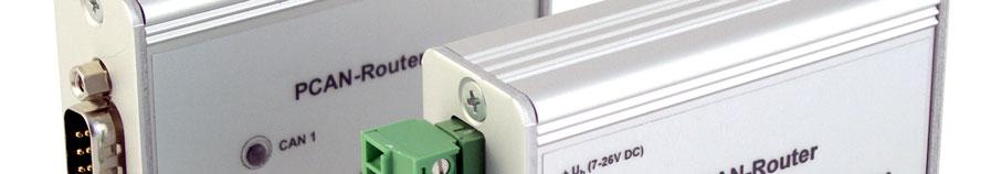
7 2 Connectors and Coding Solder Bridges The PCAN-Router is supplied in two versions which differ in the type of connections and the signals provided in addition to the CAN channels: with two 9-pin D-Sub connectors, additional digital input (IPEH ) with a 10-pin screw terminal block, additional serial interface (IPEH P) For direct access to the serial and debugging ports of the microcontroller, additional yet not equipped connector panels are available on the PCAN-Router s board. Furthermore the board has four coding solder bridges in order to assign a fixed status to the corresponding input bits of the microcontroller. The following subsections describe each connector assignment. 7
8 2.1 D-Sub Connector (IPEH only) The D-Sub connectors are used for the CAN channels CAN1 and CAN2. The power supply can be provided via both connectors. The supply connections +U b1 and +U b2 are connected internally in a reactionless configuration. This means that different power sources can be connected, if applicable. The CAN1 connector also offers a pin to activate the bootloader (Boot CAN1, see section 6.1 Uploading Firmware via CAN on page 22) and the CAN2 connector a digital input (Din0) which can be interpreted by the microcontroller. Figure 1: CAN1 and CAN2 D-Sub connector pins Pin Function connector CAN1 Function connector CAN2 1 Not used Not used 2 CAN1_L CAN2_L 3 GND GND 4 Reserved (LIN) Not used 5 SHIELD SHIELD 6 Boot CAN1 (high-active) Not used 7 CAN1_H CAN2_H 8 Not used Din0 (low-active) 9 Supply +U b1 ( V DC) Supply +U b2 ( V DC) See also chapter 3 Port Assignment of the Microcontroller on page 13. 8
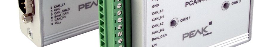
9 2.2 Screw Terminal Block (IPEH P only) Apart from power supply and CAN channels, the screw terminal block includes connections for a serial interface with RS-232 levels. Figure 2: Screw terminal block connections Terminal Function 1 Supply +U b ( V DC) 2 GND 3 CAN1_L 4 CAN1_H 5 CAN2_L 6 CAN2_H 7 Boot CAN1 (high-active) 8 Reserved (LIN) 9 RS-232 RxD 10 RS-232 TxD See also chapter 3 Port Assignment of the Microcontroller on page 13. 9
10 2.3 J4 Connector Panel: Serial Ports The non-equipped connector panel J4 on the PCAN-Router s board provides an additional access option to the serial ports of the LPC2129 or LPC2194/01 microcontroller (μc). Figure 3: Distribution of pins in connection panel J4 Pin Signal Port μc 1 RxD0 P0.1 2 TxD0 P0.0 3 Not used 4 /Boot_ser P GND V The RxD0 and TxD0 signals are forwarded to a level converter for the RS-232 standard. The PCAN-Router version with screw terminal block provides access to the adjusted signals at terminals 9 (RS-232 RxD) and 10 (RS-232 TxD). Attention! The RxD0 (pin 1) and TxD0 (pin 2) signals in connector panel J4 are designed for TTL levels only. Using RS- 232 levels at these connections can cause damage to the PCAN- Router s electronics. 10
11 2.4 J5 Connector Panel: JTAG Ports The non-equipped connector panel J5 on the PCAN-Router s board provides an additional access option to the JTAG ports of the LPC2129 or LPC2194/01 microcontroller (μc) for hardware debugging. Figure 4: Distribution of pins in connection panel J5 Pin Signal Port μc Internal wiring 1 GND 2 GND 3 /Reset /Reset Pull-up V 5 TCK P1.29 Pull-down (R30) 6 TMS P1.30 Pull-up 7 TDO P1.27 Pull-up 8 TDI P1.28 Pull-up 9 RTCK P1.26 Pull-down (R31) 10 TRST P1.31 Pull-up If constant internal pull-down wiring of the TCK or RTCK signals is not suitable for your purposes, you can remove the respective pulldown resistor on the PCAN-Router s board by soldering it out. Both resistors (each 10 kω) are located next to the J5 connector panel J5 (see figure). Figure 5: Position of pull-down resistors next to the J5 connector panel 11
12 2.5 Coding Solder Bridges The four positions for coding solder bridges (ID 0-3) are each assigned to one port of the microcontroller LPC 2129 or LPC2194/01 (μc): Position Port μc P0.4 P0.5 P0.6 P0.7 Position is jumpered open Status at the port Low High The status of the ports is relevant in the following cases: The loaded firmware is programmed so that it reads the status at the corresponding ports of the microcontroller. E.g. the activation of certain functions of the firmware or the coding of an ID is conceivable here. When uploading a firmware via CAN, the PCAN-Router is identified by a 4-bit ID which is determined by the solder bridges. A bit is set (1), if the corresponding solder bridge position is open (default setting: ID 15, all positions open). Position Binary digit Decimal equivalent See also section 6.1 Uploading Firmware via CAN on page
13 3 Port Assignment of the Microcontroller The following table lists the used inputs and outputs (ports) of the LPC2129 and LPC2194/01 microcontroller (μc) and their function in the PCAN-Router. Port I/O μc function Signal Active Function/connection 1 (μc) P0.0 O TxD UART0 TxD0 Serial communication, Transmit, J4:2 or STB:10 (RS- 232 levels) P0.1 I RxD UART0 RxD0 Serial communication, Receive, J4:1 or STB:9 (RS-232 levels) P0.2 I, O SCL SCL I 2 C bus to the EEPROM P0.3 I, O SDA SDA Microchip 24LC02B or Atmel AT24C256B 2 P0.4 I Port pin ID0 High Coding solder bridges on P0.5 I Port pin ID1 High board (ID 0-3), jumpered = Low P0.6 I Port pin ID2 High P0.7 I Port pin ID3 High P0.8 O TxD UART1 LIN_TxD LIN Transmit 3 P0.9 I RxD UART1 LIN_RxD LIN Receive 3 P0.10 O Port pin LIN_en High Enable LIN transceiver 3 P0.12 O Port pin Reserved 1 CAN1/2:n Pin n of the respective D-Sub connector STB:n Terminal n on the screw terminal block J4/5:n Pin n of the respective connector panel on the board 2 PCAN-Router serial numbers starting at This function is available in the optional PCAN-Router version with LIN transceiver only. 13
14 Port I/O μc function Signal Active Function/connection 1 (μc) P0.13 I, O Port pin P0.14 I Port pin /Boot_ser Low Activate flashing via serial interface, J4:4 P0.15 I Port pin /Boot_CAN Low Activate flashing via CAN 1 with 500 kbit/s, CAN1:9 and STB:7 (due to wiring highactive) P0.17 O Port pin V24_en High Deactivate the RS-232 converter by Low level (activated by default); possibility for energy saving P0.19 I Port pin Switch High Digital input Din0, CAN2:8 (due to wiring low-active) P0.21 O Port pin CAN_en_2 Low Activate the respective CAN P0.22 O Port pin CAN_en_1 Low transceiver 4 P0.23 I RD2 CAN2_RxD CAN 2 Receive P0.24 O TD2 CAN2_TxD CAN 2 Transmit P0.25 I RD1 CAN1_RxD CAN 1 Receive TD1 O TD1 CAN1_TxD CAN 1 Transmit P0.27 I Analog input V-Power2 Measure voltage +U b2, maximum value (0x03FF) corresponds to approx V P0.28 I Analog input V-Power1 Measure voltage +U b1 or +U b, maximum value (0x03FF) corresponds to approx V P0.29 I Analog input Is at GND P0.30 I Analog input Is at 1.8 V (microcontroller supply) 4 After resetting the microcontroller, the CAN transceivers are deactivated and must be reactivated to use them. 14
15 Port I/O μc function Signal Active Function/connection 1 (μc) P1.16 O 5 Port pin Low LED CAN 1 red P1.17 O 5 Port pin Low LED CAN 1 green P1.18 O 5 Port pin Low LED CAN 2 red P1.19 O 5 Port pin Low LED CAN 2 green P1.26 JTAG interface RTCK Debugging, J5:9 P1.27 JTAG interface TDO Debugging, J5:7 P1.28 JTAG interface TDI Debugging, J5:8 P1.29 JTAG interface TCK Debugging, J5:5 P1.30 JTAG interface TMS Debugging, J5:6 P1.31 JTAG interface TRST Debugging, J5:10 5 It may occur that an LED glows slightly when the respective output is inactive. If you would like to prevent this, your firmware must change the port type to input (I). Before switching on the LED again, the respective port type must be set to output (O). 15
16 4 Operation The PCAN-Router is activated by applying the voltage power to the respective input pins (see chapter 2 Connectors and Coding Solder Bridges). The firmware in the flash memory is subsequently run. The PCAN-Router is supplied with a demo firmware which forwards CAN messages 1:1 between the two channels at 500 kbit/s. An incoming CAN message causes a change between green and orange of the LED status indication for the respective CAN channel. The source code for the demo firmware is included on the supplied CD in the directory Example. 16
17 5 Software This chapter deals with the installation of the program package WinARM and gives notes about the CAN software library and the demo firmware. 5.1 Installing the WinARM Package WinARM is collection of tools to develop applications for ARM processors and microcontrollers on Windows platforms. The package includes the GNU GCC compiler for C and C++. The installation of the WinARM package is done in two major steps, the decompression of the ZIP archive and the setup of additional search paths under Windows Decompressing the ZIP Archive From the supplied CD, directory Compiler, decompress the ZIP archive WinARM zip to C:\, including all contained subdirectories. During this action the directory C:\WinARM and subdirectories are created. You can get more information about the WinARM package by starting the file readme.htm from the installation directory (C:\WinARM). In the web the WinARM project is found under the following address: 17
18 5.1.2 Setting up Additional Search Paths In order to enable Windows to find the development tools on calling, the according directories must be added to the search paths (environment variable PATH): C:\WinARM\bin;C:\WinARM\utils\bin; Do the following to setup the additional search paths: 1. Under Windows 2000 and XP make sure that you are logged in as user with administrator privileges. 2. Press the key combination + Pause. Under Windows 2000 und XP the dialog box System Properties is shown, under Windows Vista the window System. 3. Windows Vista only: Click on Advanced system settings. Eventually you must enter an administrator password and confirm to continue. The dialog box System Properties is shown. 4. Open the tab Advanced and on this tab click on Environment Variables. The corresponding dialog box is shown. 18


19 5. In the area System variables click on the item Path and then on Edit. The dialog box Edit System Variable is shown. 6. Add the following character string to the already existing contents of the field Variable value: C:\WinARM\bin;C:\WinARM\utils\bin; Make sure that this character string is separated from the previous contents by a semicolon (;) and without a space. 7. Close this and each preceding dialog box with OK. Note: The new search paths are effective only for programs and command prompts that are started afterwards. 19
20 5.2 CAN Software Library The development of applications for the PCAN-Router is supported by the CAN software library libpcan-routergnu1.6.0s.a (short: library), a binary file. The library is documented in the header file can.h. You find both files in the directory Example on the supplied CD. The current version 1.6 of the library supports all models of the PCAN-Router. You can use software code that is based on previous versions of the library with version 1.6 without any changes. If your firmware shall be executed on PCAN-Routers with serial numbers starting at 00300, the use of a library with a version of 1.6 or higher is necessary. The table entries of the CAN ID filter differ between the microcontrollers LPC2129 and LPC2194/01. This is taken into account with the mentioned library version. 5.3 Demo Firmware Beside the library, the directory Example on the CD contains the source code for a demo firmware which is implemented on the PCAN-Router on delivery. The demo firmware forwards CAN messages 1:1 between the two CAN channels at 500 kbit/s. An incoming CAN message causes a change between green and orange of the LED status indication for the respective CAN channel Compiling the Demo Firmware Do the following to compile the demo firmware under Windows: 1. Copy the directory Example from the supplied CD to the local hard disk. 20
21 2. Open a command prompt by using the Windows Start menu. Alternatively you can press the key combination + R and enter cmd.exe as program to be executed. 3. At the command prompt change to the directory Example that has been copied before. 4. Execute the following command in order to clean-up the target directories (i.e..out) from files that have been generated earlier: make clean 5. Execute the following command to compile the demo firmware: make all If the compiler has finished without errors ( Errors: none ), you can find the firmware file Start.bin in the subdirectory.out. This file is then used for firmware upload to the PCAN-Router (see chapter 6 Firmware Upload on page 22). 21
22 6 Firmware Upload The microcontroller in the PCAN-Router can be equipped with new firmware in two different ways: Via CAN. The scope of delivery includes a special Windows program to copy the firmware from a PC to the PCAN-Router. This is the recommended method for a firmware upload. Via the serial interface or the serial connections of the microcontroller. For the latter access to the board is needed. 6.1 Uploading Firmware via CAN System Requirements CAN interface of the PCAN series for the computer (e.g. PCAN- USB) Windows 2000 SP4 / XP SP2 / Vista (32 Bit) If you want to update several PCAN-Routers connected to the same CAN bus, a unique ID has to be assigned to each PCAN- Router. See section 2.5 Coding Solder Bridges on page Preparing Hardware and Software Perform the following steps for preparation of the hardware: 1. Switch the PCAN-Router off by disconnecting it from the power supply. 2. Establish a connection between Boot CAN1 and +U b1 or +U b at the connectors of the PCAN-Router. 22
 and Boot CAN1 (7) on the screw terminal block (IPEH-002210-P only) This measure later applies the \"Boot CAN1 connection with a high level. 3.")
23 Figure 6: Schematic representation of a connection between the pins +U b1 (6) and Boot CAN1 (9) on the CAN 1 D-Sub connector (IPEH only) Figure 7: Schematic representation of a connection between the pins +U b (1) and Boot CAN1 (7) on the screw terminal block (IPEH P only) This measure later applies the "Boot CAN1 connection with a high level. 3. Connect the PCAN-Router's CAN bus 1 with a CAN interface connected to the computer. Uploading firmware via CAN bus 2 is not possible. Attention! Risk of short circuit! A CAN cable with D-Sub connectors must not have a connection on pin 6, as it can be seen on 1:1 cables, for example. At other CAN nodes (e.g. a CAN interface of the PCAN series) this line may be applied to the mass. Damage or destruction of the electronics is a possible consequence. Perform the following steps for preparation of the software: 1. Copy the directory PcanFlash from the supplied CD to the local hard disk. The contained Windows software that copies the Firmware via CAN (PcanFlash.exe) can only be started from a data carrier that is writable. 2. From the copied directory PcanFlash execute the program Pcan2.cpl. The dialog box Properties of CAN Hardware is shown. 23


24 Figure 8: Dialog box for selection of the used CAN hardware (here: PCAN-USB interface) 3. Select the used CAN interface and confirm the selection with OK. 4. From the directory PcanFlash execute the program NetCfg32.exe. Figure 9: A PCAN net with 500 kbit/s is assigned to the PCAN-USB interface. 5. Check, if a PCAN net with a transfer rate of 500 kbit/s is set up for the used CAN interface. If this is the case, you can continue with the following section Uploading the Firmware. 24

25 6. In the tree view right-click on the entry of the used CAN interface and select the command New Net. The dialog box Net Properties is opened. Figure 10: Setting up a new net with a transfer rate of 500 kbit/s 7. Assign an arbitrary name to the new net in the field Name (in this example: Flash Net ), set the transfer rate to 500 kbit/s in the field Baud rate, and confirm these settings with OK. 8. Execute the menu command File Save all (alternatively: ) in order to enable the changes Uploading the Firmware The process of copying new firmware to the PCAN-Router is as follows: 1. Ensure that a connection is established between the Boot CAN1 and +U b1 or +U b connections of the PCAN- Router (details: see above). 2. Switch the PCAN-Router on by applying voltage supply. Due to the High level at the Boot CAN connection, the PCAN-Router starts the CAN boot loader. This can be 25
 button in order to call up the dialog box. 5.")
26 identified by two orange LEDs. Starting with version 2 of the CAN bootloader (standard in PCAN-Router modules with serial numbers starting at 00300) the LED CAN 1 flashes. 3. Run the program PcanFlash.exe under Windows from the local hard drive. 4. Click on the (Options) button in order to call up the dialog box. 5. In the Options dialog box click on the button next to the File name field in order to select the requested firmware file to be uploaded. Figure 11: The Options dialog box with a selected firmware file 6. Click on the OK button. 7. Ensure that the PCAN Flash program is connected to the requested CAN network. Click the (Connect) button in order to change the selection in the dialog box, if required. 26
 button in order to detect the PCAN- Router connected to the CAN bus. An entry for the PCAN-Router appears in the main window.")
 button in order to start uploading the new firmware to the PCAN-Router. Observe the status display at the bottom of the window.")
27 Figure 12: Selection of the CAN network connected to the PCAN-USB interface 8. Click the (Detect) button in order to detect the PCAN- Router connected to the CAN bus. An entry for the PCAN-Router appears in the main window. Figure 13: Firmware upload start 9. Select the entry for the PCAN-Router. 10. Click the (Program) button in order to start uploading the new firmware to the PCAN-Router. Observe the status display at the bottom of the window. The process was successful, if the last message to appear is Flashing of module(s) finished!. 11. Disconnect the power supply from the PCAN-Router. 27
28 12. Disconnect Boot CAN1 from +U b1 or +U b. You can now use the PCAN-Router with the new firmware. 6.2 Uploading Firmware via the Serial Connections This section shows how to initiate the microcontroller s bootloader. The actual upload process depends on the upload software used which is supplied by a third party and is not described here. You can get more details from our customer support (address on page 2). Do the following to initiate the microcontroller's bootloader: 1. Switch the PCAN-Router off by disconnecting it from the power supply. 2. Open the housing of the PCAN-Router by removing the screws in order to gain access to the board. 3. Establish a connection on the J4 connector panel between pin 4 (\Boot_ser) and pin 5 (GND). Figure 14: Schematic representation of a connection of the pins \Boot_ser (4) und GND (5) on connector panel J4 4. Establish a serial connection to the computer or program adapter. This is carried out either via the RS-232 interface (IPEH P only) or via the serial ports of the microcontroller (TTL levels). See also chapter 2 Connectors and Coding Solder Bridges on page 7. 28
29 5. Switch the PCAN-Router on by applying voltage supply. Due to the Low level on port P0.14 of the microcontroller, the PCAN-Router starts the boot loader for serial copying. Neither LED is illuminated. 29
30 7 Frequently Asked Questions (FAQ) Problem/Question Answer Where can I retrieve You can download several documents more information about about these microcontroller types via the microcontrollers the internet from the homepage of NXP. LPC2129 and Address: LPC2194/01? 30
31 8 Technical Specifications Power supply Voltage supply (+U b ) V DC ± 5% Current consumption max. 70 ma at 12 V Functionality Microcontroller Add-on memory CAN LIN RS-232 Digital input (Din0) Status indication Connectors Up to ser. no : NXP (Philips) LPC2129 Starting at ser. no : NXP (Philips) LPC2194/01 each with a clock speed of 12 MHz Firmware upload via CAN with special bootloader or serial Up to ser. no : 2 kbit, EEPROM Microchip 24LC02B, I 2 C link Starting at ser. no : 256 kbit, EEPROM Atmel AT24C256B, I 2 C link 2 x High-speed CAN (ISO ), transceiver 82C250, transfer rates 40 kbit/s 1 MBit/s (lower transfer rates on request) 1 LIN channel (on request) RxD and TxD serial connections with RS-232 levels (IPEH P only) Low-active, max. level +U b (IPEH only) 2 duo LEDs IPEH : 2 x D-Sub connector, 9-pin, assignment according to CiA DS102-2 IPEH P: 1 x screw terminal block, 10-pin, Phoenix, RM 3.81 Continued on the next page 31
32 Measures Dimension Housing: 24 x 55 x 66 mm (15/16 x 2 3/16 x 2 5/8 inches) Board: 17 x 51 x 65 mm (11/16 x 2 x 2 9/16 inches) (see also Appendix B Dimension Drawing on page 34) Weight IPEH : 100 g (3.5 oz.) IPEH P: 100 g (3.5 oz., incl. screw terminal block) Environment Operating temperature Temperature for storage and transport Relative humidity C ( F) C ( F) 15% - 90 %, not condensing 32


33 Appendix A Certificates A.1 CE 33
34 Appendix B Dimension Drawing Figure 15: Plan view of the PCAN-Router housing 34
PCAN-Router Universal CAN Converter. User Manual V1.2.0
 PCAN-Router Universal CAN Converter User Manual V1.2.0 Products taken into account Product Name Model Item Number PCAN-Router 2 D-Sub connectors, IPEH-002210 additional digital input PCAN-Router Screw
PCAN-Router FD Universal, programmable Converter for CAN FD and CAN. User Manual. Document version ( )
") PCAN-Router FD Universal, programmable Converter for CAN FD and CAN User Manual Document version 1.0.1 (2017-01-27) Relevant products Product Name Model Part number PCAN-Router FD 2 D-Sub connectors IPEH-002214
PCAN-Router FD Universal, programmable Converter for CAN FD and CAN User Manual Document version 1.0.1 (2017-01-27) Relevant products Product Name Model Part number PCAN-Router FD 2 D-Sub connectors IPEH-002214
PCAN-Flash Windows-Software for Flashing Firmware via CAN. Operation Instructions. Document version ( )
") PCAN-Flash Windows-Software for Flashing Firmware via CAN Operation Instructions Document version 1.2.0 (2017-11-20) Relevant products Product Name Model Part number PCAN-Flash from version 2.0 PCAN-Router
PCAN-Flash Windows-Software for Flashing Firmware via CAN Operation Instructions Document version 1.2.0 (2017-11-20) Relevant products Product Name Model Part number PCAN-Flash from version 2.0 PCAN-Router
PCAN-Optoadapter Plug-on Adapter for Decoupling CAN Networks. User Manual. Document version ( )
") PCAN-Optoadapter Plug-on Adapter for Decoupling CAN Networks User Manual Document version 3.0.1 (2013-10-21) Products taken into account Product Name Model Part number PCAN-Optoadapter IPEH-002038 CANopen
PCAN-Optoadapter Plug-on Adapter for Decoupling CAN Networks User Manual Document version 3.0.1 (2013-10-21) Products taken into account Product Name Model Part number PCAN-Optoadapter IPEH-002038 CANopen
MU-Thermocouple1 CAN. Temperature Measurement Unit with CAN Connection. User Manual
 MU-Thermocouple1 CAN Temperature Measurement Unit with CAN Connection User Manual Products taken into account Product Name Model Item Number MU-Thermocouple1 CAN Metal-cased measuring unit IPEH-002205
PCAN-PCI Express. PCI Express to CAN Interface. User Manual
 PCAN-PCI Express PCI Express to CAN Interface User Manual Products taken into account Product Name Model Item Number Ser. no. PCAN-PCI Express Single One CAN channel IPEH-003024 Channel PCAN-PCI Express
PCAN-PCI. PCI to CAN Interface. User Manual
 PCAN-PCI PCI to CAN Interface User Manual Products taken into account Product Name Model Item Number PCAN-PCI Single Channel One CAN channel IPEH-002064 PCAN-PCI Dual Channel Two CAN channels IPEH-002065
PCAN-TJA1054 Bus Converter High-Speed CAN to Low-Speed CAN. User Manual. Document version ( )
") PCAN-TJA1054 Bus Converter High-Speed CAN to Low-Speed CAN User Manual Document version 2.1.0 (2013-11-15) Products taken into account Product Name Model Part number PCAN-TJA1054 IPEH-002039 CANopen and
PCAN-TJA1054 Bus Converter High-Speed CAN to Low-Speed CAN User Manual Document version 2.1.0 (2013-11-15) Products taken into account Product Name Model Part number PCAN-TJA1054 IPEH-002039 CANopen and
PCAN-MicroMod Digital 1 & 2 Application-specific PCAN-MicroMod Motherboard. User Manual V1.10.0
 PCAN-MicroMod Digital 1 & 2 Application-specific PCAN-MicroMod Motherboard User Manual V1.10.0 Products taken into account Product Name Model Part number PCAN-MicroMod Digital 1 Including casing and PCAN-
PCAN-Repeater 2-Channel CAN Repeater with galvanic isolation. User Manual V1.0.0
 PCAN-Repeater 2-Channel CAN Repeater with galvanic isolation User Manual V1.0.0 Products taken into account Product Name Model Item Number PCAN-Repeater Industry IPEH-004038 All product names mentioned
PCAN-PCI (ISO) Adapter Card PC-PCI to High-speed CAN. User Manual
 Adapter Card PC-PCI to High-speed CAN. User Manual") PCAN-PCI (ISO) Adapter Card PC-PCI to High-speed CAN User Manual Products taken into account Product Name Model Item Number PCAN-PCI Single Channel One CAN channel IPEH-002064 PCAN-PCI Dual Channel Two
PCAN-PCI (ISO) Adapter Card PC-PCI to High-speed CAN User Manual Products taken into account Product Name Model Item Number PCAN-PCI Single Channel One CAN channel IPEH-002064 PCAN-PCI Dual Channel Two
PCAN-MicroMod Analog 2 Application-specific PCAN-MicroMod Motherboard. User Manual. Document version ( )
") PCAN-MicroMod Analog 2 Application-specific PCAN-MicroMod Motherboard User Manual Document version 1.12.2 (2017-09-12) Relevant products Product Name Model Part number PCAN-MicroMod Analog 2 Including
PCAN-MicroMod Analog 2 Application-specific PCAN-MicroMod Motherboard User Manual Document version 1.12.2 (2017-09-12) Relevant products Product Name Model Part number PCAN-MicroMod Analog 2 Including
PCAN-PCI Express PCI Express to CAN Interface. User Manual V2.0.0
 PCAN-PCI Express PCI Express to CAN Interface User Manual V2.0.0 Products taken into account Product Name Model Item Number Ser. no. PCAN-PCI Express Single One CAN channel IPEH-003024 Channel PCAN-PCI
PCAN-B10011S. Converter High-speed CAN to Truck Trailer CAN. User Manual
 PCAN-B10011S Converter High-speed CAN to Truck Trailer CAN User Manual Products taken into account Product Name Model Item Number PCAN-B10011S IPEH-002041 Last Updates March 23, 2005 First edition February
PCAN-PCI/104-Express PCI/104-Express to CAN Interface. User Manual V2.1.0
 PCAN-PCI/104-Express PCI/104-Express to CAN Interface User Manual V2.1.0 Products taken into account Product Name Model Part Number PCAN-PCI/104-Express One CAN channel IPEH-003054 Single Channel PCAN-PCI/104-Express
PCAN-Repeater DR CAN Repeater for the Decoupling of Bus Segments. User Manual V1.1.0
 PCAN-Repeater DR CAN Repeater for the Decoupling of Bus Segments User Manual V1.1.0 Products taken into account Product Name Model Part Number PCAN-Repeater DR Industry IPEH-004038 All product names mentioned
PCAN-MicroMod Analog 1 Application-specific PCAN-MicroMod Motherboard. User Manual. Document version ( )
") PCAN-MicroMod Analog 1 Application-specific PCAN-MicroMod Motherboard User Manual Document version 1.11.3 (2017-09-12) Relevant products Product Name Model Part number PCAN-MicroMod Analog 1 Including
PCAN-MicroMod Analog 1 Application-specific PCAN-MicroMod Motherboard User Manual Document version 1.11.3 (2017-09-12) Relevant products Product Name Model Part number PCAN-MicroMod Analog 1 Including
PCAN-B10011S Bus Converter High-speed CAN to Truck-Trailer CAN. User Manual V2.0.0
 PCAN-B10011S Bus Converter High-speed CAN to Truck-Trailer CAN User Manual V2.0.0 Products taken into account Product Name Model Part number PCAN-B10011S IPEH-002041 CANopen and CiA are registered community
PCAN-Repeater DR CAN Repeater for the Decoupling of Bus Segments. User Manual. Document version ( )
") PCAN-Repeater DR CAN Repeater for the Decoupling of Bus Segments User Manual Document version 2.0.0 (2018-02-20) Relevant products Product Name Model Part number PCAN-Repeater DR Industry IPEH-004038 PCAN
PCAN-Repeater DR CAN Repeater for the Decoupling of Bus Segments User Manual Document version 2.0.0 (2018-02-20) Relevant products Product Name Model Part number PCAN-Repeater DR Industry IPEH-004038 PCAN
PCAN-ExpressCard ExpressCard to CAN Interface. User Manual V2.0.0
 PCAN-ExpressCard ExpressCard to CAN Interface User Manual V2.0.0 Products taken into account Product Name Model Item Number PCAN-ExpressCard Single One CAN channel IPEH-003000 Channel PCAN-ExpressCard
PCAN-Dongle. Parallel Port to CAN Interface. User Manual
 PCAN-Dongle Parallel Port to CAN Interface User Manual Products taken into account Product Name Model Item Number PCAN-Dongle DIN IPEH-002015 PCAN-Dongle PS/2 IPEH-002019 PCAN-Dongle opto-decoupled PS/2
PCAN-PCI PCI to CAN Interface. User Manual V2.1.0
 PCAN-PCI PCI to CAN Interface User Manual V2.1.0 Products taken into account Product Name Model Part Number PCAN-PCI Single Channel One CAN channel IPEH-002064 PCAN-PCI Dual Channel Two CAN channels IPEH-002065
PCAN-MicroMod Mix 2 Application-specific PCAN-MicroMod Motherboard. User Manual. Document version ( )
") PCAN-MicroMod Mix 2 Application-specific PCAN-MicroMod Motherboard User Manual Document version 1.11.1 (2014-03-11) Products taken into account Product Name Model Part number PCAN-MicroMod Mix 2 Including
PCAN-MicroMod Mix 2 Application-specific PCAN-MicroMod Motherboard User Manual Document version 1.11.1 (2014-03-11) Products taken into account Product Name Model Part number PCAN-MicroMod Mix 2 Including
PCAN-PCI Express PCI Express to CAN Interface. User Manual V3.2.0
 PCAN-PCI Express PCI Express to CAN Interface User Manual V3.2.0 Products taken into account Product Name Model Part Number Ser. No. PCAN-PCI Express Single One CAN channel IPEH-003026 Channel galv. isolated
PCAN-cPCI CompactPCI to CAN Interface. User Manual V2.0.0
 PCAN-cPCI CompactPCI to CAN Interface User Manual V2.0.0 Products taken into account Product Name Model Item Number PCAN-cPCI Dual Channel 2 CAN channels, galvanic IPEH-003021 opto-decoupled isolation
PCAN-PC/104-Plus Quad Four-Channel CAN Interface for PC/104-Plus. User Manual V1.0.1
 PCAN-PC/104-Plus Quad Four-Channel CAN Interface for PC/104-Plus User Manual V1.0.1 Products taken into account Product Name Model Part Number PCAN-PC/104-Plus Quad Four CAN channels IPEH-002099 On request
PCAN-USB CAN Interface for USB. User Manual. Document version ( )
") PCAN-USB CAN Interface for USB User Manual Document version 2.2.1 (2014-04-29) Products taken into account Product Name Model Part Number PCAN-USB IPEH-002021 PCAN-USB opto-decoupled Galvanic isolation
PCAN-USB CAN Interface for USB User Manual Document version 2.2.1 (2014-04-29) Products taken into account Product Name Model Part Number PCAN-USB IPEH-002021 PCAN-USB opto-decoupled Galvanic isolation
PCAN-MicroMod Mix 3 Application-specific PCAN-MicroMod Motherboard. User Manual V2.1.0
 PCAN-MicroMod Mix 3 Application-specific PCAN-MicroMod Motherboard User Manual V2.1.0 Products taken into account Product Name Model Part number PCAN-MicroMod Mix 3 Including casing and PCAN- IPEH-002206
PCAN-MicroMod Mix 2 Application-specific PCAN-MicroMod Motherboard. User Manual. Document version ( )
") PCAN-MicroMod Mix 2 Application-specific PCAN-MicroMod Motherboard User Manual Document version 1.11.3 (2017-09-12) Relevant products Product Name Model Part number PCAN-MicroMod Mix 2 Including casing
PCAN-MicroMod Mix 2 Application-specific PCAN-MicroMod Motherboard User Manual Document version 1.11.3 (2017-09-12) Relevant products Product Name Model Part number PCAN-MicroMod Mix 2 Including casing
PCAN-PCI Express CAN Interface for PCI Express. User Manual. Document version ( )
") PCAN-PCI Express CAN Interface for PCI Express User Manual Document version 3.5.1 (2017-01-30) Relevant products Product name Model Part number Ser. no. PCAN-PCI Express Single One CAN channel IPEH-003026
PCAN-PCI Express CAN Interface for PCI Express User Manual Document version 3.5.1 (2017-01-30) Relevant products Product name Model Part number Ser. no. PCAN-PCI Express Single One CAN channel IPEH-003026
PCAN-PCI/104-Express CAN Interface for PCI/104-Express. User Manual. Document version ( )
") PCAN-PCI/104-Express CAN Interface for PCI/104-Express User Manual Document version 2.6.2 (2018-01-10) Relevant products Product name Model Part number Ser.-nr. PCAN-PCI/104-Express Single Channel optodecoupled
PCAN-PCI/104-Express CAN Interface for PCI/104-Express User Manual Document version 2.6.2 (2018-01-10) Relevant products Product name Model Part number Ser.-nr. PCAN-PCI/104-Express Single Channel optodecoupled
PCAN-PC Card PC Card to CAN Interface. User Manual V2.1.1
 PCAN-PC Card PC Card to CAN Interface User Manual V2.1.1 Products taken into account Product Name Model Part Number PCAN-PC Card Single Channel One CAN channel IPEH-002090 PCAN-PC Card Dual Channel Two
PCAN-PC/104 CAN Interface for PC/104. User Manual V2.2.3
 PCAN-PC/104 CAN Interface for PC/104 User Manual V2.2.3 Products taken into account Product Name Model Part number PCAN-PC/104 Single Channel One CAN channel IPEH-002054 PCAN-PC/104 Dual Channel Two CAN
PCAN-LIN Interface for LIN, CAN, and RS-232. User Manual. Document version ( )
") PCAN-LIN Interface for LIN, CAN, and RS-232 User Manual Document version 2.2.1 (2017-02-03) Relevant products Product Name Model Part number PCAN-LIN High-speed CAN (HS-CAN) IPEH-002025 PCAN-LIN Low-speed
PCAN-LIN Interface for LIN, CAN, and RS-232 User Manual Document version 2.2.1 (2017-02-03) Relevant products Product Name Model Part number PCAN-LIN High-speed CAN (HS-CAN) IPEH-002025 PCAN-LIN Low-speed
PCAN-PC/104-Plus Quad Four-Channel CAN Interface for PC/104-Plus. User Manual. Document version ( )
") PCAN-PC/104-Plus Quad Four-Channel CAN Interface for PC/104-Plus User Manual Document version 1.3.1 (2017-01-30) Relevant products Product name Model Part number PCAN-PC/104-Plus Quad Four CAN channels
PCAN-PC/104-Plus Quad Four-Channel CAN Interface for PC/104-Plus User Manual Document version 1.3.1 (2017-01-30) Relevant products Product name Model Part number PCAN-PC/104-Plus Quad Four CAN channels
Mix 2. Motherboard for the PCAN-MicroMod. User Manual
 Mix 2 Motherboard for the PCAN-MicroMod User Manual Products taken into account Product Name Model Item Number PCAN-MicroMod Motherboard Including casing and IPEH-002203 Mix 2 PCAN-MicroMod The picture
PCAN-MiniDiag FD PCAN-MiniDiag Diagnostic Device for CAN FD FD Buses. User Manual. Document version ( )
") PCAN-MiniDiag FD PCAN-MiniDiag Diagnostic Device for CAN FD FD Buses User Manual Document version 1.0.0 (2019-01-24) Relevant products Product name PCAN-MiniDiag FD Part number IPEH-003070 PCAN is a registered
PCAN-MiniDiag FD PCAN-MiniDiag Diagnostic Device for CAN FD FD Buses User Manual Document version 1.0.0 (2019-01-24) Relevant products Product name PCAN-MiniDiag FD Part number IPEH-003070 PCAN is a registered
PCAN-cPCI CAN Interface for CompactPCI. User Manual. Document version ( )
") PCAN-cPCI CAN Interface for CompactPCI User Manual Document version 2.4.1 (2017-02-09) Relevant products Product name Model Part number PCAN-cPCI Dual Channel 2 CAN channels, galvanic IPEH-003021 opto-decoupled
PCAN-cPCI CAN Interface for CompactPCI User Manual Document version 2.4.1 (2017-02-09) Relevant products Product name Model Part number PCAN-cPCI Dual Channel 2 CAN channels, galvanic IPEH-003021 opto-decoupled
PCAN-ExpressCard CAN Interface for the ExpressCard Slot. User Manual. Document version ( )
") PCAN-ExpressCard CAN Interface for the ExpressCard Slot User Manual Document version 2.4.0 (2016-05-11) Relevant products Product name Model Part number PCAN-ExpressCard Single One CAN channel IPEH-003000
PCAN-ExpressCard CAN Interface for the ExpressCard Slot User Manual Document version 2.4.0 (2016-05-11) Relevant products Product name Model Part number PCAN-ExpressCard Single One CAN channel IPEH-003000
PCAN-USB CAN Interface for USB. User Manual. Document version ( )
") PCAN-USB CAN Interface for USB User Manual Document version 2.5.1 (2017-01-27) Relevant products Product name Model Part number PCAN-USB IPEH-002021 PCAN-USB opto-decoupled Galvanic isolation for CAN interface
PCAN-USB CAN Interface for USB User Manual Document version 2.5.1 (2017-01-27) Relevant products Product name Model Part number PCAN-USB IPEH-002021 PCAN-USB opto-decoupled Galvanic isolation for CAN interface
Mix 2. Motherboard for the PCAN-MicroMod. User Manual
 Mix 2 Motherboard for the PCAN-MicroMod User Manual Products taken into account Product Name Model Item Number PCAN-MicroMod Motherboard Mix 2 Including casing and PCAN-MicroMod IPEH-002086 Windows is
PCAN-ExpressCard 34 CAN Interface for the ExpressCard/34 Slot. User Manual. Document version ( )
") PCAN-ExpressCard 34 CAN Interface for the ExpressCard/34 Slot User Manual Document version 1.2.1 (2017-02-10) Relevant products Product name Model Part number PCAN-ExpressCard 34 One CAN channel IPEH-003004
PCAN-ExpressCard 34 CAN Interface for the ExpressCard/34 Slot User Manual Document version 1.2.1 (2017-02-10) Relevant products Product name Model Part number PCAN-ExpressCard 34 One CAN channel IPEH-003004
PCAN-USB Pro CAN/LIN Interface for High-Speed USB 2.0. User Manual. Document version ( )
") PCAN-USB Pro CAN/LIN Interface for High-Speed USB 2.0 User Manual Document version 2.3.1 (2014-04-30) Products taken into account Product Name Model Part number PCAN-USB Pro IPEH-002061 CANopen and CiA
PCAN-USB Pro CAN/LIN Interface for High-Speed USB 2.0 User Manual Document version 2.3.1 (2014-04-30) Products taken into account Product Name Model Part number PCAN-USB Pro IPEH-002061 CANopen and CiA
PLIN-LWL Optical Coupler for LIN Data Transmission. User Manual. Document version ( )
") PLIN-LWL Optical Coupler for LIN Data Transmission User Manual Document version 1.1.1 (2017-01-27) Relevant products Product Name Model Part number PLIN-LWL IPEH-004049 All product names mentioned in this
PLIN-LWL Optical Coupler for LIN Data Transmission User Manual Document version 1.1.1 (2017-01-27) Relevant products Product Name Model Part number PLIN-LWL IPEH-004049 All product names mentioned in this
PCAN-PCI Express FD CAN FD Interface for PCI Express. User Manual. Document version ( )
") PCAN-PCI Express FD CAN FD Interface for PCI Express User Manual Document version 1.2.0 (2017-06-15) Relevant products Product name Model Part number PCAN-PCI Express FD Single Channel PCAN-PCI Express
PCAN-PCI Express FD CAN FD Interface for PCI Express User Manual Document version 1.2.0 (2017-06-15) Relevant products Product name Model Part number PCAN-PCI Express FD Single Channel PCAN-PCI Express
PCAN-miniPCIe FD CAN FD Interface for PCI Express Mini. User Manual. Document version ( )
") PCAN-miniPCIe FD CAN FD Interface for PCI Express Mini User Manual Document version 1.0.1 (2018-08-21) Relevant products Product name Model Part number PCAN-miniPCIe FD Single One CAN channel, galvanic
PCAN-miniPCIe FD CAN FD Interface for PCI Express Mini User Manual Document version 1.0.1 (2018-08-21) Relevant products Product name Model Part number PCAN-miniPCIe FD Single One CAN channel, galvanic
PCAN-USB FD CAN FD Interface for High-Speed USB 2.0. User Manual. Document version ( )
") PCAN-USB FD CAN FD Interface for High-Speed USB 2.0 User Manual Document version 1.3.1 (2017-01-27) Relevant products Product name Model Part number PCAN-USB FD IPEH-004022 CANopen and CiA are registered
PCAN-USB FD CAN FD Interface for High-Speed USB 2.0 User Manual Document version 1.3.1 (2017-01-27) Relevant products Product name Model Part number PCAN-USB FD IPEH-004022 CANopen and CiA are registered
PLIN-Slave Test-Slave for the LIN Bus with Various I/Os. User Manual V1.1.0
 PLIN-Slave Test-Slave for the LIN Bus with Various I/Os User Manual V1.1.0 Products taken into account Product name Model Part number PLIN-Slave Eval-Board IPEH-004050 All product names mentioned in this
PCAN-Dongle. User Manual. Parallel Port to CAN Interface. Document version ( )
") PCAN-Dongle Parallel Port to CAN Interface User Manual Document version 2.0.1 (2017-02-09) Relevant products Product name Model Part number PCAN-Dongle PS/2 IPEH-002019 PCAN-Dongle opto-decoupled PS/2
PCAN-Dongle Parallel Port to CAN Interface User Manual Document version 2.0.1 (2017-02-09) Relevant products Product name Model Part number PCAN-Dongle PS/2 IPEH-002019 PCAN-Dongle opto-decoupled PS/2
PCAN-M.2 CAN FD Interface for M.2 (PCIe) User Manual. Document version ( )
 User Manual. Document version ( )") PCAN-M.2 CAN FD Interface for M.2 (PCIe) User Manual Document version 1.1.0 (2018-04-25) Relevant products Product name Model Part number PCAN-M.2 Single Channel One CAN channel, galvanic IPEH-004083 isolation
PCAN-M.2 CAN FD Interface for M.2 (PCIe) User Manual Document version 1.1.0 (2018-04-25) Relevant products Product name Model Part number PCAN-M.2 Single Channel One CAN channel, galvanic IPEH-004083 isolation
PCAN-USB X6 CAN FD Interface for High-Speed USB 2.0. User Manual. Document version ( )
") PCAN-USB X6 CAN FD Interface for High-Speed USB 2.0 User Manual Document version 1.1.2 (2018-02-22) Relevant products Product name Model Part number PCAN-USB X6 with D-Sub connectors Red corners IPEH-004062
PCAN-USB X6 CAN FD Interface for High-Speed USB 2.0 User Manual Document version 1.1.2 (2018-02-22) Relevant products Product name Model Part number PCAN-USB X6 with D-Sub connectors Red corners IPEH-004062
PCAN-Router Pro 4-Channel CAN Router with Data Logger. User Manual. Document version ( )
") PCAN-Router Pro 4-Channel CAN Router with Data Logger User Manual Document version 2.4.0 (2017-08-04) Relevant products Product Name Part number Model PCAN-Router Pro IPEH-002212 Firmware version 1.4.x
PCAN-Router Pro 4-Channel CAN Router with Data Logger User Manual Document version 2.4.0 (2017-08-04) Relevant products Product Name Part number Model PCAN-Router Pro IPEH-002212 Firmware version 1.4.x
PCAN-USB Pro FD CAN FD and LIN Interface for High-Speed USB 2.0. User Manual. Document version ( )
") PCAN-USB Pro FD CAN FD and LIN Interface for High-Speed USB 2.0 User Manual Document version 1.3.1 (2017-01-27) Relevant products Product name Model Part number PCAN-USB Pro FD IPEH-004061 CANopen and
PCAN-USB Pro FD CAN FD and LIN Interface for High-Speed USB 2.0 User Manual Document version 1.3.1 (2017-01-27) Relevant products Product name Model Part number PCAN-USB Pro FD IPEH-004061 CANopen and
User Manual. CANopenIA-M0. Starter Kit
 User Manual CANopenIA-M0 Starter Kit Edition 8 March 2017 Page 2 of 21 The information given in this document was compiled and checked carefully. Nevertheless ESS assumes no liability for any mistakes.
User Manual For CP-JR ARM7 USB-LPC2148 / EXP
 CP-JR ARM7 USB-LPC2148 / EXP 38 CR-JR ARM7 USB-LPC2148 which is a Board Microcontroller ARM7TDMI-S Core uses Microcontroller 16/32-Bit 64 Pin as Low Power type to be a permanent MCU on board and uses MCU
Easy Kit Board Manual
 User s Manual, V1.0, June2008 Easy Kit Board Manual Easy Kit - XC88x Microcontrollers Edition 2008-06 Published by Infineon Technologies AG, 81726 München, Germany Infineon Technologies AG 2008. All Rights
Installation and Operating Instructions. webremote
 Installation and Operating Instructions webremote 02/2012 PSG Plastic Service GmbH 1 Installations- und Bedienungsanleitung webremote Table of Contents 1 Typographical Conventions 2 webremote 2.1 Overview
PCAN-GPS Programmable Position Sensor Module with CAN Connection. User Manual. Document version ( )
") PCAN-GPS Programmable Position Sensor Module with CAN Connection User Manual Document version 1.2.2 (2018-08-03) Relevant products Product name Model Part number PCAN-GPS IPEH-002110 PCAN is a registered
PCAN-GPS Programmable Position Sensor Module with CAN Connection User Manual Document version 1.2.2 (2018-08-03) Relevant products Product name Model Part number PCAN-GPS IPEH-002110 PCAN is a registered
BUS CONVERTER (TJA1054) User Manual
 User Manual") BUS CONVERTER (TJA1054) User Manual Contents 1 License Regulations... 1 2 Overview... 2 3 Application Note... 3 3.1 Pin Assignment of the Sub-D Connectors... 4 3.2 Bus Termination Low-speed CAN... 5 3.3
BUS CONVERTER (TJA1054) User Manual Contents 1 License Regulations... 1 2 Overview... 2 3 Application Note... 3 3.1 Pin Assignment of the Sub-D Connectors... 4 3.2 Bus Termination Low-speed CAN... 5 3.3
MegaAVR-DEVelopment Board Progressive Resources LLC 4105 Vincennes Road Indianapolis, IN (317) (317) FAX
 (317) FAX") MegaAVR-DEVelopment Board Progressive Resources LLC 4105 Vincennes Road Indianapolis, IN 46268 (317) 471-1577 (317) 471-1580 FAX http://www.prllc.com GENERAL The MegaAVR-Development board is designed for
MegaAVR-DEVelopment Board Progressive Resources LLC 4105 Vincennes Road Indianapolis, IN 46268 (317) 471-1577 (317) 471-1580 FAX http://www.prllc.com GENERAL The MegaAVR-Development board is designed for
PEAK-System Technik. New products for 2010 / Accessories
 PEAK-System Technik New products for 2010 / 2011 Accessories PEAK-System >> CAN Interface PCAN-PCI/104-Express PCI/104-Express to CAN Interface The PCAN-PCI/104-Express card allows the connection of two
PCAN-Wireless Gateway CAN to WLAN Gateway. User Manual. Document version ( )
") PCAN-Wireless Gateway CAN to WLAN Gateway User Manual Document version 1.4.1 (2018-07-10) Relevant products Product Name Model Software Version Part Number PCAN-Wireless Gateway Industry 2.7.0 IPEH-004020
PCAN-Wireless Gateway CAN to WLAN Gateway User Manual Document version 1.4.1 (2018-07-10) Relevant products Product Name Model Software Version Part Number PCAN-Wireless Gateway Industry 2.7.0 IPEH-004020
COM-RZN1D - Hardware Manual
 COM-RZN1D - Hardware Manual Hardware Manual 4 / 01.10.2018 emtrion GmbH Copyright 2018 emtrion GmbH All rights reserved. This documentation may not be photocopied or recorded on any electronic media without
Mega128-DEVelopment Board Progressive Resources LLC 4105 Vincennes Road Indianapolis, IN (317) (317) FAX
 (317) FAX") Mega128-DEVelopment Board Progressive Resources LLC 4105 Vincennes Road Indianapolis, IN 46268 (317) 471-1577 (317) 471-1580 FAX http://www.prllc.com GENERAL The Mega128-Development board is designed for
Mega128-DEVelopment Board Progressive Resources LLC 4105 Vincennes Road Indianapolis, IN 46268 (317) 471-1577 (317) 471-1580 FAX http://www.prllc.com GENERAL The Mega128-Development board is designed for
XC164CS Prototype Board
 XC164CS Prototype Board Features: Small PCB (95 x 57 mm) with ground plane. o Designed to fit inside a Pac Tec FLX-4624 ABS enclosure Infineon XC164CS 16-bit single-chip microcontroller o 166SV2 core o
LVX Control Unit. Features:
 Date 2013-02-28 Control Unit Features: Most parameters can be defined as required for your interfaces. You decide which information is output and how. Fast cycle times, just a few µs/beam. Maximum beam-count
Evaluation & Development Kit for Freescale PowerPC MPC5517 Microcontroller
 _ V1.0 User s Manual Evaluation & Development Kit for Freescale PowerPC MPC5517 Microcontroller Ordering code ITMPC5517 Copyright 2007 isystem AG. All rights reserved. winidea is a trademark of isystem
Hardware Manual RM CANview Gateway
 Hardware Manual RM CANview Gateway 2008 RM Michaelides Software & Elektronik GmbH Donaustraße 14 D-36043 Fulda Germany cvgateway-hw-e.doc Table Of Contents 1 Legal Regulations... 3 2 About the CANview
bdiaccess Installation Manual MPC85xx/P10xx/P20xx JTAG interface library by Abatron AG Manual Version 1.01 for BDI3000
 bdiaccess JTAG interface library MPC85xx/P10xx/P20xx Installation Manual Manual Version 1.01 for BDI3000 1992-2009 by Abatron AG bdiaccess for BDI3000 (MPC85xx/P10xx/P20xx) Installation Manual 2 1 Introduction...
ARDUINO LEONARDO ETH Code: A000022
 ARDUINO LEONARDO ETH Code: A000022 All the fun of a Leonardo, plus an Ethernet port to extend your project to the IoT world. You can control sensors and actuators via the internet as a client or server.
Manual 601: : USB/RS232. Specifications. Contents. Options
 Page 1 ATE-601 601: : USB/RS232 I/O Controller - 8 Inputs, 4/8 Relays The ATE-500/600 series is a range of modular I/O controllers. It uses small standardized boards which allows you to configure the system
MicroBolt. Microcomputer/Controller Featuring the Philips LPC2106 FEATURES
 Microcomputer/Controller Featuring the Philips LPC2106 FEATURES Powerful 60 MHz, 32-bit ARM processing core. Pin compatible with 24 pin Stamp-like controllers. Small size complete computer/controller with
EVAcharge SE - Datasheet
 EVAcharge SE - Datasheet Datasheet (valid for board revision V0R4 or higher) Document history Revision 1.0 2013-10-10 Initial release 1.1 2013-11-06 Typo corrections 1.2 2014-05-13 Removed serial IF 1.3
Auxiliary Board MP-Bus HZS 562
 MP BUS AUXILIARY BOARD HZS 562 Auxiliary Board MP-Bus HZS 562 The MP bus interface electronics connect a CAN bus system with an MP bus system. The electronics are used as an MP bus master to control MP
Hardware Manual RM Display 2501 S01..S04
 Hardware Manual RM Display 2501 S01..S04 Table of Contents 1 Legal Regulations...3 2 About the Display 2501...4 3 Important information for using RM Display 2501...5 4 Disposal...5 5 Installation...6 5.1
USB-to-I2C Basic. Hardware User s Manual.
 USB-to-I2C Basic Hardware User s Manual http://www.i2ctools.com/ Information provided in this document is solely for use with the USB-to-I2C product from SB Solutions, Inc. SB Solutions, Inc. reserves
Mega128-Net Mega128-Net Mega128 AVR Boot Loader Mega128-Net
 Mega128-Net Development Board Progressive Resources LLC 4105 Vincennes Road Indianapolis, IN 46268 (317) 471-1577 (317) 471-1580 FAX http://www.prllc.com GENERAL The Mega128-Net development board is designed
User Manual. cmt-svr Startup Guide
 User Manual cmt-svr Startup Guide Table of Contents Chapter 1 Overview... 1 1.1 Specification... 1 1.2 Dimensions... 2 1.3 Connector pin designations... 3 1.4 USB host port and SD card slot... 3 1.5 Ethernet
Hardware Manual RM Display 2401
 Hardware Manual RM Display 2401 Table of Contents 1 Legal Regulations...3 2 About the Display 2401...4 3 Important information for using RM Display 2401...5 4 Disposal...5 5 Installation...6 5.1 VESA 100
User Manual. cmt-svr Startup Guide
 User Manual cmt-svr Startup Guide Table of Contents Chapter 1 Overview... 1 1.1 Specification... 1 1.2 Dimensions... 2 1.3 Connector pin designations... 3 1.4 USB host port and SD card slot... 3 1.5 Ethernet
ACU6. Technical Reference Manual. Specifications Interfacing Dimensions. Document topics. ANSARI Controller Unit Type 6 technical reference manual
 ACU6 Technical Reference Manual ANSARI Controller Unit Type 6 technical reference manual Document topics Specifications Interfacing Dimensions Document Version: 1.03 13. January 2013 By ANSARI GmbH Friedrich-Ebert-Damm
Arduino Uno. Arduino Uno R3 Front. Arduino Uno R2 Front
 Arduino Uno Arduino Uno R3 Front Arduino Uno R2 Front Arduino Uno SMD Arduino Uno R3 Back Arduino Uno Front Arduino Uno Back Overview The Arduino Uno is a microcontroller board based on the ATmega328 (datasheet).
Wireshark Dissector for PCAN-Gateways IPEH , IPEH ,IPEH (A) User Manual. Document version 1.0 ( )
 User Manual. Document version 1.0 ( )") Wireshark Dissector for PCAN-Gateways IPEH-004010, IPEH-004011,IPEH-004020(A) User Manual Document version 1.0 (2018-07-23) Relevant products Product name Model Part number PCAN-Ethernet Gateway DR PCAN-Wireless
Wireshark Dissector for PCAN-Gateways IPEH-004010, IPEH-004011,IPEH-004020(A) User Manual Document version 1.0 (2018-07-23) Relevant products Product name Model Part number PCAN-Ethernet Gateway DR PCAN-Wireless
Atmel AVR datasheet. Matrix Multimedia Atmel AVR Board EB Contents
 Atmel AVR datasheet Contents 1. About this document 2. General information 3. Board overview 4. Getting Started 5. Block schematic and description Appendix A. Circuit diagram B. Compatible AVR device C.
8051 Intermidiate Development Board. Product Manual. Contents. 1) Overview 2) Features 3) Using the board 4) Troubleshooting and getting help
 Overview 2) Features 3) Using the board 4) Troubleshooting and getting help") 8051 Intermidiate Development Board Product Manual Contents 1) Overview 2) Features 3) Using the board 4) Troubleshooting and getting help 1. Overview 2. Features The board is built on a high quality FR-4(1.6
8051 Intermidiate Development Board Product Manual Contents 1) Overview 2) Features 3) Using the board 4) Troubleshooting and getting help 1. Overview 2. Features The board is built on a high quality FR-4(1.6
BIG8051. Development system. User manual
 BIG8051 User manual All s development systems represent irreplaceable tools for programming and developing microcontroller-based devices. Carefully chosen components and the use of machines of the last
EVAcharge SE - datasheet
 EVAcharge SE - datasheet Data Sheet (valid for board revision V0R4 or higher) Document history Revision 1.0 2013-10-10 Initial release 1.1 2013-11-06 Typo corrections 1.2 2014-05-13 Removed serial IF 1.3
MRS Electronic, Inc Winner Circle Dayton, OH (937) Datasheet CAN Relay Box 16. Page 1 of 8 Version 1.
 Datasheet CAN Relay Box 16. Page 1 of 8 Version 1.") Page 1 of 8 Version 1.4 Technical Data Housing Aluminum housing Connector PCB connection header S2C-SMT 3.50/32/90LF Housing Dimensions 109.4 x 105.8 x 34.7 mm Weight 332 g Temperature Range (ambient)
Page 1 of 8 Version 1.4 Technical Data Housing Aluminum housing Connector PCB connection header S2C-SMT 3.50/32/90LF Housing Dimensions 109.4 x 105.8 x 34.7 mm Weight 332 g Temperature Range (ambient)
XC2000 series Board Manual, V.1.0, June XC2000 Easy Kit. Board REV. V1.0. Microcontrollers. Never stop thinking.
 series Board Manual, V..0, June 2007 Board REV. V.0 Microcontrollers Never stop thinking. Edition 2007-06 Published by Infineon Technologies AG 8726 Mühen, Germany Infineon Technologies AG 2007. All Rights
MRS Electronic GmbH. Datasheet CAN I/O & CAN PLC CAN I/O & CAN PLC. CAN I/O & CAN PLC Site 1 of 5 Version 1.0
 Site 1 of 5 Version 1.0 Technical data Construction Connector Housing dimensions Weight Ambient temperature Protection class Plastic housing with side flaps 22 pin Molex Mini Fit Junior 60 x 60 x 30 mm
This guide covers the basic operation and use of your PCAN-Diag FD. You can find a detailed documentation in PDF format...
 PCAN-Diag FD Quick Start Guide This guide covers the basic operation and use of your PCAN-Diag FD. You can find a detailed documentation in PDF format...... on the PCAN-Diag FD memory card in the directory:
General Operating, Maintenance and Installation Manual
 General Operating, Maintenance and Installation Manual Hardware Platform for Protocol Converter Small Embedded Controller - SEC2-91056 Erlangen Telephone +49 9131 92076-0 Fax: +49 9131 92076-10 Internet:
MX Educational Target User Manual
 MX Educational Target User Manual Revision History Date Description Initial release. Table of Contents 1. Introduction... 4 1.1. Module Models... 4 1.2. Package Contents... 4 1.3. Key Hardware Features...
Hardware Manual RM CANview
 Hardware Manual RM CANview 1998-2005 RM Michaelides Software & Elektronik GmbH Donaustraße 14 D-36043 Fulda Germany cv_hw_e.doc Table of Contents 1 Legal Regulations...3 2 About the CANview...4 3 Important
6LoWPAN Development Platform Saker Manual
 6LoWPAN Development Platform Saker Manual WEPTECH elektronik GmbH Page 1 of 19 V.1.0.1 1. Table of Content 1. General information... 4 1.1 1.2 1.3 1.4 1.5 Copyright protection... 4 Warranty information...
This manual provides information for the final user application developer on how to use SPC57S-Discovery microcontroller evaluation board.
 User manual SPC570S-DISP: Discovery+ Evaluation Board Introduction This manual provides information for the final user application developer on how to use SPC57S-Discovery microcontroller evaluation board.
Lantech LSC-1102B SERIAL TO TCPIP CONVERTER. User Manual
 Lantech LSC-1102B SERIAL TO TCPIP CONVERTER User Manual V1.0 Sep 2016 Table of Contents 1. Introduction 3 Overview 4 Product Specifications 8 2. Description & Installation 10 Product Panel Views 10 LED
Brief Instruction. 4.2 ISDN devices. 4.2 GSM devices MDH 502 MDH 536 MDH 506 MDH 512 MDH 542 MDH 522
 4.2 ISDN devices 502 506 512 522 532 536 542 552 556 Voltage VDC 24 Current ma (24V) 60 60 70 90 90 100 80 100 110 Protection class (IP) 20 Range of use Dry Surroundings Temperatures (Plant) 0 50 C Temperatures
HAND HELD PROGRAMMER QUICK START GUIDE
 HAND HELD PROGRAMMER QUICK START GUIDE IMPORTANT INFORMATION 1) Do not leave the programmer connected to the PC, adapters or a target system, as this will drain the battery. Installing Software 1) Run
TAP Expander Blackhawk Emulator Expansion Pod. Document Part Number: REV B
 CORELIS TAP Expander TAP Expander Blackhawk Emulator Expansion Pod User s Manual Document Part Number: 70397 REV B Copyright 2008 Corelis Inc. 13100 Alondra Blvd. Suite 102 Cerritos, CA 90703-2262 Telephone: