Disclaimer of Liability
|
|
|
- Natalie Stevenson
- 5 years ago
- Views:
Transcription
1
2 Safety Guidelines: Warning notices must be observed to ensure personal safety as well as that of others, and to protect the product and the connected equipment. These warning notices are accompanied by a clarification of the level of caution to be observed. Qualified Personnel: This device/system may only be set up and operated in conjunction with this manual. Qualified personnel are only authorized to install and operate this equipment in accordance with established safety practices and standards. Unit Repair and Excluded Liability: The user is responsible for all changes and repairs made to the device by the user or the user s agent. All new components are to be provided by Siemens Milltronics Process Instruments. Restrict repair to faulty components only. Do not reuse faulty components. Warning: Cardboard shipping package provides limited humidity and moisture protection. This product can only function properly and safely if it is correctly transported, stored, installed, set up, operated, and maintained. This product is intended for use in industrial areas. Operation of this equipment in a residential area may cause interference to several frequency based communications. Note: Always use product in accordance with specifications. Copyright Siemens AG All Rights Reserved This document is available in bound version and in electronic version. We encourage users to purchase authorized bound manuals, or to view electronic versions as designed and authored by Siemens Milltronics Process Instruments. Siemens Milltronics Process Instruments will not be responsible for the contents of partial or whole reproductions of either bound or electronic versions. Disclaimer of Liability While we have verified the contents of this manual for agreement with the instrumentation described, variations remain possible. Thus we cannot guarantee full agreement. The contents of this manual are regularly reviewed and corrections are included in subsequent editions. We welcome all suggestions for improvement. Technical data subject to change. MILLTRONICS is a registered trademark of Siemens Milltronics Process Instruments. Contact SMPI Technical Publications European Authorized Representative at the following address: Technical Publications Siemens AG Siemens AG Industry Sector Siemens Milltronics Process Instruments Karlsruhe 1954 Technology Drive, P.O. Box 4225 Deutschland Peterborough, Ontario, Canada, K9J 7B1 techpubs.smpi@siemens.com For a selection of Siemens Milltronics level measurement manuals, go to: www. siemens.com/processautomation. Under Process Instrumentation, select Level Measurement and then go to the manual archive listed under the product family. For a selection of Siemens Milltronics weighing manuals, go to: www. siemens.com/processautomation. Under Weighing Technology, select Continuous Weighing Systems and then go to the manual archive listed under the product family. Siemens AG 2011
3 Table of Contents Safety Notes...1 The Manual...1 Technical Support...2 SmartLinx PROFIBUS DP...3 Table of Contents Specifications...4 Installation...5 Compatibility...5 Software Compatibility...5 Hardware Compatibility...6 Cable Connector...8 Termination Switch...10 Operation...11 Error Status LEDs...11 Error Conditions of the Red Diagnostics Light...12 Operation LED...12 Communication Setup...13 GSD Files...13 Baud Rate...13 Bus Address...13 Configuring the Slave Device...14 Map Element Selection...15 P762 Map Element Selection parameter...15 Module Identification...17 P794 SmartLinx Module Type...17 P795 SmartLinx Protocol...17 P634: Communication Totalizer Resolution...18 Application Layer...19 Parameter Indexes...19 Primary Index...19 Secondary Index...20 Data Access Methods...20 Direct Access...20 Multiple Parameter Access (MPA)...21 Single Parameter Access (SPA)...22 Data Map: Level Products...24 Write Block...24 Read Block...27 Data Map: Mass Dynamic Products...30 Write Block...30 Read Block...34 i
4 Table of Contents Data Types...40 Integer...40 Bit Values...40 Unsigned Double Precision Integer (UINT32)...41 Split Values...41 Text Messages...42 Relay Function Codes (P111 in Level Products Only)...43 Troubleshooting...45 Generally...45 Technical Support or Product Feedback...45 Appendix A Reducing the amount of data being transferred over the Bus...46 Level Products...46 Write Block...47 Read Block...49 Mass Dynamics Products...51 Write Block...52 Read Block...54 Index ii
5 Safety Notes Special attention must be paid to warnings and notes highlighted from the rest of the text by grey boxes. WARNING: relates to a caution symbol on the product, and means that failure to observe the necessary precautions can result in death, serious injury, and/or considerable material damage. WARNING: means that failure to observe the necessary precautions can result in death, serious injury, and/or considerable material damage. SmartLinx PROFIBUS DP CAUTION: means that failure to observe the necessary precautions can result in considerable material damage. Note: means important information about the product or that part of the operating manual. The Manual Note: Please follow the installation and operating procedures for a quick, trouble-free installation and to ensure the maximum accuracy and reliability of your Siemens Milltronics SmartLinx PROFIBUS DP module. This manual applies to the SmartLinx PROFIBUS DP module only. This manual will help you install and connect a Siemens Milltronics SmartLinx PROFIBUS DP module, and set it up for communication with a master device on a PROFIBUS DP network. The manual is targeted at a technical audience in the industrial communications field with a sound working knowledge of PROFIBUS DP. We always welcome questions, comments, or suggestions about manual content, design, and accessibility. Please direct your questions or comments to techpubs.smpi@siemens.com. For the complete library of Siemens Milltronics manuals, go to 7ML19981AQ03 SmartLinx PROFIBUS DP INSTRUCTION MANUAL Page 1
6 SmarttLinx PROFIBUS DP Technical Support Support is available 24 hours a day. To find your local Siemens Automation Office address, phone number and fax number go to: Click on the tab Contacts by Product then drill down to find your product group (+Process Automation > +Process Instrumentation > +Level Measuring Instruments). Select the team Technical Support. Click on Next. Click on the appropriate continent, then select the country followed by the city. Click on Next. For on-line technical support go to: Enter the device name or order number, then click on Search, and select the appropriate product type. Click on Next. You will be prompted to enter a keyword describing your issue. Then either browse the relevant documentation, or click on Next to a detailed description of your issue to Siemens Technical Support staff. Siemens IA/DT Technical Support Center: phone +49 (0) Page 2 SmartLinx PROFIBUS DP INSTRUCTION MANUAL 7ML19981AQ03
7 SIMATIC S7-300 RUN-P RUN STOP MRES CPU 314 SF BAF DC 5V FRCE RUN STOP X X 2 X 2 X 2 X AE00-OABO BH0 0- OAAO 321-1BH00-OAAO 322-1HE00-OAAO ma 9 0 P P C A M RUN PAR ZER O SPA N ALT RESET CLEAR ENTER DI SP TOTAL SmartLinx PROFIBUS DP Note: This product is intended for use in industrial areas. Operation of this equipment in a residential area may cause interference to several frequency based communications. The Siemens Milltronics SmartLinx 1 PROFIBUS DP module is a plug-in communications card designed to interface a Siemens Milltronics SmartLinx-compatible instrument to a PROFIBUS DP network. Only those instruments which support the PROFIBUS DP protocol can use this card. See Compatible Instruments: on page 4 for a list of SmartLinx-compatible Siemens Milltronics instruments. SmartLinx PROFIBUS DP MC 951 /16 KB 6ES7 951-OFDOO-OAAO PLC master PROFIBUS DP at 9.6 Kbaud to 12 Mbaud Siemens Milltronics instrument monitored process PROFIBUS is an open standard controlled by PROFIBUS industry groups worldwide. More information is available on the web site at Note: Siemens Milltronics does not own the PROFIBUS DP protocol. All information regarding that protocol is subject to change without notice. 1. SmartLinx is a registered trademark of Siemens Milltronics Process Instruments Inc. 7ML19981AQ03 SmartLinx PROFIBUS DP INSTRUCTION MANUAL Page 3
8 Specifications Application: compatible with a master device on a PROFIBUS bus Compatible Instruments: Specifications AiRanger XPL Plus / SITRANS LU 10 AiRanger DPL Plus / SITRANS LU 02 AiRanger SPL / SITRANS LU 01 CraneRanger InterRanger DPS 300 EnviroRanger ERS 500 Milltronics BW500 Milltronics BW500/L Milltronics SF500 MultiRanger 100/200 HydroRanger 200 Communication Settings: baud rate: 9.6 Kbaud to 12 Mbaud, automatically detected Connection: varies by Siemens Milltronics SmartLinx instrument, (see page 8) Termination: Cable: switch selectable, open or special active termination as per PROFIBUS specification (see Termination Switch on page 10) Belden PROFIBUS cable 3079A, or equivalent Page 4 SmartLinx PROFIBUS DP INSTRUCTION MANUAL 7ML19981AQ03
9 Installation The SmartLinx module is either shipped already installed in the Siemens Milltronics instrument or separately for on-site installation. Refer to the manual of your Siemens Milltronics instrument for details on module location and physical installation. Compatibility For the SmartLinx PROFIBUS card there are different hardware and software configurations available depending on the equipment used. Software Compatibility If a device is SmartLinx ready, it will work with the correct SmartLinx card for that device. However, if the firmware version is a lower number than the one listed below, the Map Element Selection Parameter (P762) will not be available. Also, for the BW500, BW500/L, and SF500, the read block will be a smaller size. Product Software Rev. Product Software Rev. AiRanger XPL Plus / SITRANS LU 10 Milltronics BW500/L 3.13 AiRanger DPL Plus / Milltronics BW SITRANS LU 02 Milltronics SF AiRanger SPL / MultiRanger SITRANS LU 01 InterRanger DPS 300 MultiRanger 200 HydroRanger EnviroRanger ERS Installation Retrofits If you are replacing an older SmartLinx device with a new SmartLinx device, and you are using any product other than the BW500, BW500/L, or SF500, then you can use the default values for P762. If you are replacing a BW500, BW500/L, or SF500 with a new device, then set P762 primary index 15 = 0, and P762 primary index 16 = 0. 7ML19981AQ03 SmartLinx PROFIBUS DP INSTRUCTION MANUAL Page 5
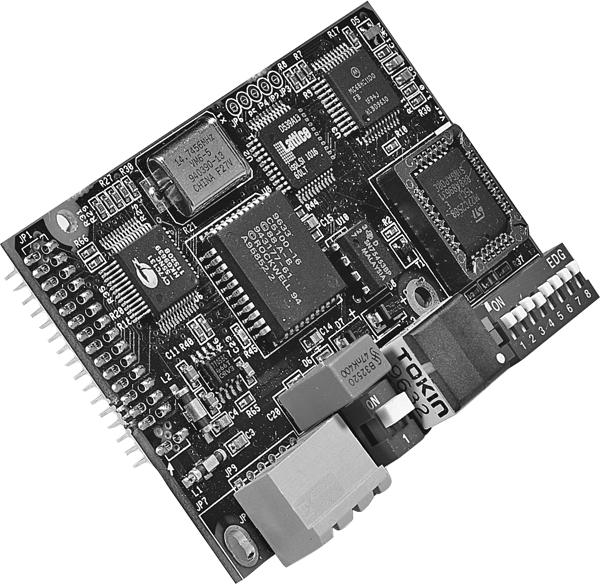
10 Hardware Compatibility All available SmartLinx card configurations are shown here for reference. The card shown below is compatible with the following Siemens Milltronics units: AiRanger XPL Plus / SITRANS LU 10 AiRanger DPL Plus / SITRANS LU 02 AiRanger SPL / SITRANS LU 01 CraneRanger InterRanger DPS 300 module connector (underside, 32-pin) to Siemens Milltronics host mounting hole Installation address switches mounting hole status LEDs termination switch terminal block, removable Page 6 SmartLinx PROFIBUS DP INSTRUCTION MANUAL 7ML19981AQ03
11 The card shown below is compatible with the following Siemens Milltronics units: EnviroRanger ERS 500 (Wall Mount) Milltronics BW500 Milltronics BW500/L Milltronics SF500 MultiRanger 100/200 HydroRanger 200 module connector (underside, 34-pin) to Siemens Milltronics host mounting hole operation LED mounting hole address switches termination switch terminal block, removable status LEDs Note: Install the SmartLinx card so that the mounting holes align and the pin connectors will mate correctly. Correct cable routing is important for electromagnetic noise suppression. Follow the routing instructions contained your unit s instruction manual. Installation 7ML19981AQ03 SmartLinx PROFIBUS DP INSTRUCTION MANUAL Page 7
12 The card shown below is compatible with EnviroRanger ERS 500 (Rack or Panel Mount) module connector (underside, 34-pin) to Siemens Milltronics host mounting hole operation LED mounting hole address switches termination switch module connector (underside, 10-pin) status LEDs Installation Cable Connector Connect using Belden PROFIBUS cable 3079A or equivalent and terminate according to PROFIBUS DP specification and conventions. AiRanger / SITRANS LU Series, CraneRanger, InterRanger DPS 300 bus +5V (Vcc) bus ground (GND) A-line B-line bus shield A-line B-line bus cable shield Note: To daisy-chain devices, connect both the outgoing and the incoming wires to terminals 3 and 4. Then if you have to remove the connector, the bus will still be active. Page 8 SmartLinx PROFIBUS DP INSTRUCTION MANUAL 7ML19981AQ03
13 EnviroRanger ERS 500 (Wallmount), Milltronics BW500, Milltronics BW500/L, Milltronics SF500, MultiRanger 100/200, HydroRanger 200 bus +5V (Vcc) bus ground (GND) A-line B-line bus cable shield RTS Note: To daisy-chain devices with the BW500, BW500/L or SF500, connect both wires to the existing A-line and B-line terminals. RTS is used in some equipment to determine the direction of transmission. In normal applications only A-line, B-line, and shield, are used. EnviroRanger ERS 500 (Rack or Panel Mount) When using a SmartLinx card with the EnviroRanger (rack or panel mount) all wiring is made to the EnviroRanger terminal board. The PROFIBUS connections map to the EnviroRanger terminal board as shown: EnviroRanger Connection 65 Gnd_bus 66 RTS 1 68 A 69 B 71 V_bus +5V 67 bus cable shield Installation 1. RTS is used in some equipment to determine the direction of transmission. In normal applications only A-line, B-line, and shield, are used. 7ML19981AQ03 SmartLinx PROFIBUS DP INSTRUCTION MANUAL Page 9
14 Termination Switch 1 Termination Setting Switch Position open (not used) off +5V 390Ω Line A 220Ω on Line GND 390Ω PROFIBUS DP requires termination of the bus at both end points. See the PROFIBUS DP specifications for details. Installation 1. The termination switch is not present on all cards. Page 10 SmartLinx PROFIBUS DP INSTRUCTION MANUAL 7ML19981AQ03
15 Operation Communication on the PROFIBUS DP link is indicated by the SmartLinx LEDs. Error Status LEDs AiRanger / SITRANS LU Series, CraneRanger, InterRanger DPS 300 Green LED ON module is operational Amber LED ON data is being exchanged OFF data is not being exchanged Red LED ON no communication between bus and module / Bus error OFF normal operation EnviroRanger ERS 500, Milltronics BW500, Milltronics BW500/L, Milltronics SF500, MultiRanger 100/ 200, HydroRanger 200 Not used Green Online module is online Off: Red (blinking): Diagnostics Module is ok Module is in an error state. See the error descriptions (page 12) and use the master to solve the problem. Red Offline Module is offline and no communication is possible. Operation 7ML19981AQ03 SmartLinx PROFIBUS DP INSTRUCTION MANUAL Page 11
16 Error Conditions of the Red Diagnostics Light 1Hz Error in Configuration Indicates that the I/O length variable set during initialization is not equal to the length set during configuration of the network. See Configuring the Slave Device on page 14 for lengths supported by the SmartLinx module, and see your PLC documentation for setting the I/O length variable. 2Hz Error in User Parameter Data Indicates that the length and / or contents of the user parameter data set during initialization of the module is greater than the length and/or contents set during configuration of the network. See Configuring the Slave Device on page 14 for supported lengths. 4Hz Error in Initialization Consult your Siemens Milltronics representative. Operation LED EnviroRanger ERS 500, Milltronics BW500, Milltronics BW500/L, Milltronics SF500, MultiRanger 100/200, HydroRanger 200 LED blinks orange as the module is initialized blinks green during normal operation Operation Page 12 SmartLinx PROFIBUS DP INSTRUCTION MANUAL 7ML19981AQ03
17 Communication Setup The SmartLinx PROFIBUS DP module is a slave on the bus, and does not use any Siemens Milltronics instrument parameters for configuration. Set the rotary switches on the module to the desired slave address: other settings are provided in the GSD file or are automatically detected. GSD Files PROFIBUS master devices require a configuration file for each slave device on the network. This file configures the master for the capabilities and limitations of the slave. For the SmartLinx PROFIBUS DP module these files are: AiRanger / SITRANS LU Series hms_1002.gsd BW500, BW500/L, SF500, hms1003.gsd HydroRanger 200, MultiRanger 100/200, and ERS 500 Both files are supplied on the floppy disk that is shipped with the module. The file hms_1002.gsd uses the manufacturer s I.D. number of 1002 hexadecimal (4,098 decimal). The file hms1003.gsd uses the manufacturer s I.D. number 1003 hexadecimal (4,099 decimal). Baud Rate The SmartLinx PROFIBUS module automatically configures itself to the correct baud rate for the PROFIBUS DP network. Follow the PROFIBUS guidelines with regards to bus length and baud rate. Bus Address Set the two rotary switches to the address for this slave. Use a slave address switch in the range 03 to 99. This example shows the value 06. 7ML19981AQ03 SmartLinx PROFIBUS DP INSTRUCTION MANUAL Page 13 Communications Setup
18 Configuring the Slave Device Use the configuration software (or any equivalent master commands) to configure the slave. Refer to the information that came with the PROFIBUS master. The Siemens Milltronics instrument appears as a modular type slave, and should be configured as shown below. After you import the GSD file, you can find the hardware in the hardware catalogue. If you are using Step 7, go to PROFIBUS DP > Additional Field Devices > General. For AiRanger / SITRANS LU products, select AB-DT-PDP. For all other products, select Anybus-S_PDP. Then define two universal modules: one input module and one output module. The data size of the input and output modules is dependent on P762, and on the type of unit the module is plugged into, (either Level or Mass Dynamics). (The following instructions assume that P762 is set to the default values shown in the chart on page 16.) Level Products (includes AiRanger / SITRANS LU Series, ERS 500, MultiRanger 100/200, HydroRanger 200) 42 words input (see Write Block on page 24) 13 words output (see Read Block on page 27) read and write data as 16-bit words (see Data Types on page 40) Mass Dynamics Products (includes BW500, SF500) 34 1 words input (see Write Block on page 30) 19 words output (see Read Block on page 34) read and write data as 16-bit words (see Data Types on page 40) Mass Dynamics Products (BW500/L) 23 words input (see Write Block on page 30) 10 words output (see Read Block on page 34) read and write data as 16-bit words (see Data Types on page 40) If your PROFIBUS master is not capable of handling the block sizes listed above then use multiple smaller blocks. (See next page for examples.) Communications Setup is the correct value for BW500/SF500 units that have firmware V 3.05 or greater and have all the values of P762 turned on. For older units, the input size is 31 words. Page 14 SmartLinx PROFIBUS DP INSTRUCTION MANUAL 7ML19981AQ03
19 Example: An S5-115U with an IM 308C master would use the following: For Level products: Inputs: 3 address blocks of 16, 16, and 10 words Outputs: 1address block of 13 words For Mass Dynamics products: Inputs: 3 address blocks of 16 words, 16 words, and 2 words 1 Outputs: 2 address blocks of 16 and 3 words Notes: Data is read and written with the most significant byte (MSB) first. The address and size of the Reads and Writes in the PLC must match the Siemens Milltronics device (see above). If the PLC size is smaller than the Siemens Milltronics size, an error will be displayed and only the first portion of the data will be read. PROFIBUS DP diagnostic bytes are not supported, however, some diagnostic information can be accessed via reading and writing the data areas. See Application Layer on page 19. Map Element Selection P762 Map Element Selection parameter P762 allows you to select what elements to include in the Input and Output Tables. By selecting only the data required, you can reduce the amount of data being transferred over the bus. Nots: P762 should only be modified by an advanced user who wants to limit the amount of data being transferred. See Appendix A Reducing the amount of data being transferred over the Bus on page 46 for more details. Changes do not take effect until after a power cycle. The chart on page 16 gives the default values for this parameter. If the default values are used then the configuration and Data Maps (see pages 24 and 30) in the main body of this manual remain correct. If any of these values is changed, then the Data Maps will be shortened and the configuration will change. Please see Appendix A on page 46 for details on how to use P This applies to BW500/SF500 units that have firmware V 3.05 or greater and have all the values of P762 turned on--it does not apply to older units. 7ML19981AQ03 SmartLinx PROFIBUS DP INSTRUCTION MANUAL Page 15 Communications Setup
20 P762 Index 1 AiRanger / SITRANS LU, EnviroRanger, MultiRanger Name of area Instrument status Default value 2 Reading 10 3 Alarm 10 4 Point-onpriority 5 MPA 1 6 SPA 1 7 Operating Mode Range 0 = No 1 = Yes 0 = No 1 10 = include that number of items 0 = No 1 10 = include that number of items 0 = No 1 = Yes 0 = No 1 = Yes 0 = No 1 = Yes 0 = No 1 = Yes BW500, BW500/L, SF500 Name of area Instrument status Default value SF500, BW500/L BW Rate 1 1 Load 1 1 Speed 1 1 Total 1 1 Relay Status 1 1 DI Status SPA Command Control MultiSpan PID Batch Batch Prewarn Word Order Status Batch Total Range 0 = No 1 = Yes 0 = No 1 = Yes 0 = No 1 = Yes 0 = No 1 = Yes 0 = No 1 = Yes 0 = No 1 = Yes 0 = No 1 = Yes 0 = No 1 = Yes 0 = No 1 = Yes 0 = No 1 = Yes 0 = No 1 = Yes 0 = No 1 = Yes 0 = No 1 = Yes 0 = No 1 = Yes 0 = No 1 = Yes 0 = No 1 = Yes Communications Setup 1. For firmware V 3.05, the default is 0. For all higher ersions, the default is 1. Page 16 SmartLinx PROFIBUS DP INSTRUCTION MANUAL 7ML19981AQ03
21 Module Identification Parameters P794 and P795 are used together to identify the module type and protocol used. P794 SmartLinx Module Type (Read only) Identifies the module used. Value Module 0 No module present 1 Anybus DT module 2 Anybus S module P795 SmartLinx Protocol (Read only) Identifies the protocol used: the value varies according to the module, and whether it is a type 1 or type 2. Siemens Milltronics Instrument ERS 500, BW500, BW500/L, SF500, MultiRanger 100/200 AiRanger, SITRANS LU Card P794 value P795 value AB RIO 1 72 PROFIBUS DP 2 1 DeviceNet 2 37 AB RIO 1 72 PROFIBUS DP 1 0 DeviceNet 1 24 Modbus RTU 1 57 Modem Card ML19981AQ03 SmartLinx PROFIBUS DP INSTRUCTION MANUAL Page 17 Communications Setup
22 P634: Communication Totalizer Resolution Parameter P634 is used to set the number of fixed decimal places for Total 1 and Total 2 for SmartLinx communication. Note: P634 applies only to Milltronics BW500, Milltronics BW500/L and Milltronics SF500. P634 Index Description Value # of decimal places Primary Index 1 Total 1 for SmartLinx 3 * 3 communication Primary Index 2 Total 2 for SmartLinx 3 * 3 communication * Factory setting Communications Setup Page 18 SmartLinx PROFIBUS DP INSTRUCTION MANUAL 7ML19981AQ03
23 Application Layer This section describes the meaning of data read from and written to the Siemens Milltronics SmartLinx instrument slave memory. The output words (PLC master Write operation) and input words (PLC master Read operation) are described in the Data Map for Level Products on page 24 and the Data Map for Mass Dynamic Products on page 30. Parameter Indexes Most parameters used on Siemens Milltronics SmartLinx instruments are indexed. Indexing allows a parameter to relate to more than one input or output. For example, many parameters are indexed by measurement point while others are indexed by relay output or discrete input. The way that indexes are handled in the memory map depends on the data access method used. Application Layer Primary Index An index that relates to an input or output is called a Primary Index. (On some older Siemens Milltronics products the primary index is called a point.) Example: P111[3] = 52 means P111 (Relay Control Function) for relay 3 is set to value 52. P111 [1] [2] [3] [4] [5] 52 7ML19981AQ03 SmartLinx PROFIBUS DP INSTRUCTION MANUAL Page 19
24 Secondary Index Applicaton Layer Sometimes a parameter requires a second index to allow for multiple values on an indexed input or output. For example a measurement point which calculates a reading on volume can require characterization breakpoints. These breakpoints are given on a secondary index (the primary index relates to the transducer input). An index that relates to a previously indexed parameter is called a secondary index. (On some older Siemens Milltronics products the secondary index is called a mark.) Example: P054[1,3] = 1.6m means P054 (Breakpoint Levels) for breakpoint 3 on transducer 1 is set to 1.6m P054 [1] [2] [3] [4] [5] [1] [2] [3] [4] 1.6m Data Access Methods There are three different methods used in the memory mapping to give access to the SmartLinx Instrument parameter table. They are: Direct Access Multiple Parameter Access (MPA) Single Parameter Access (SPA) Direct Access Certain values are mapped directly into words. These words can be monitored continuously but they are not configurable. Page 20 SmartLinx PROFIBUS DP INSTRUCTION MANUAL 7ML19981AQ03
25 Multiple Parameter Access (MPA) Note: MPA is used on Level products only. In Siemens Milltronics products, the memory is arranged as Parameter number, Primary Index, Secondary Index. This is a hand-shaking method where the user specifies the parameter number, secondary index, decimal place, and format, then the SmartLinx writes into a certain area all 10 primary indexes of that parameter. Application Layer Using Multiple Parameter Access (MPA) 1. In the output table of the PLC (Write Block) write the values for the parameter number, secondary Index, decimal place and format in the correct location. 2. Monitor the Input table of the PLC (Read Block), and watch for the values you wrote to appear in the appropriate locations of the Read block, then go to Step Read the requested values in the appropriate location of the Read Block. These values are continuously updated. Continue reading from these words until values for another parameter are required. At that time, go to step 1. Note: MPA values are only updated in Run mode (word 12 = 0). Parameter Indexing with MPA Primary Index The primary index is implicit in the memory address. MPA values are returned through words 21 to 30 of the Read block (see page 27). Secondary Index The secondary index is nearly always left at zero. See the Siemens Milltronics SmartLinxcompatible instrument manual for information on parameters, including those which require a secondary index. 7ML19981AQ03 SmartLinx PROFIBUS DP INSTRUCTION MANUAL Page 21
26 Single Parameter Access (SPA) Applicaton Layer Note: SPA is used on both Level and Mass Dynamics products. This is a hand-shaking method where the PLC specifies: parameter number primary index secondary index decimal place format read/write flag value With this method any value in the Siemens Milltronics product can be read or written. Note: Parameter P999 (Master Reset) is not accessible via the SmartLinx interface on Level products. Using Single Parameter Access (SPA) SPA allows continuous monitoring or demand programming of a parameter. Reading a Parameter 1. Set the Read/Write flag in the output table (Write Block) to 0, Read. 2. Write the Parameter Number, Primary Index, Secondary Index, Decimal Place, and Format in the correct locations. Note: If there is no secondary index, then place a 0 in this location. 3. Monitor the Input table of the PLC (Read Block) and watch for the values you wrote to appear in the appropriate locations, then go to Step Read the requested parameter value in the Input table (Read Block). These values are continuously updated. Continue reading from these words until values for other parameters are required. At that time, go back to step 1. Page 22 SmartLinx PROFIBUS DP INSTRUCTION MANUAL 7ML19981AQ03
27 Writing a Parameter 1. Set the Read/Write flag in the output table (Write Block) to 0, Read. 2. Write the Parameter Number, Primary Index, Secondary Index, Decimal Place, and Format in the correct locations. 3. Write the new value of the parameter into the correct location of the output memory (Write Block) 4. Verify the unit is in program mode (not needed for BW500, BW500/L and SF500). For Level see bit 10 of status word in Read Block. 5. If the unit is not in program mode, write a 1 to the operating mode word in the output memory (Write Block). Please note that writing a 1 will only work if the word is currently a 0: if not, you need to change it to 0 before writing a 1 so it can take effect. 6. Set the Read/Write flag in the output table (Write Block) to a 1 write. 7. Monitor the Input table of the PLC (Read Block) and watch for the values you wrote to appear in the appropriate locations. 8. Set Read/Write flag back to Place unit in Run mode. Application Layer Note: Parameters for Level Products should only be written to while the unit is in PROGRAM mode. If the level instrument is still in RUN mode, the written value might be ignored. 7ML19981AQ03 SmartLinx PROFIBUS DP INSTRUCTION MANUAL Page 23
28 Data Map: Level Products Applicaton Layer Note: The data maps shown for the Write and Read Blocks apply if P762 is set to the default values (see page 15). If any of these values is changed, the data map will be shortened and the configuration will change. (See Appendix A Reducing the amount of data being transferred over the Bus, on page 46.) This section describes the meaning of the data read from and written to the Siemens Milltronics SmartLinx instrument. Write Block Word Description Access Data Type 0 measurement point-on-priority direct bitmapped 1 parameter number integer 2 secondary index (mark) integer MPA 3 decimal place integer 4 format 0/1 5 parameter number integer 6 primary index (point) integer 7 secondary index (mark) integer 8 new value SPA integer 9 decimal place integer 10 format 0/1 11 read/write flag 0/1 12 operating mode direct 0/1 Word 0: Point-on-Priority Bits set the priority status of corresponding indexed points 1 to 10. bit index bit status 0 = normal 1 = priority For example, if bits 00 and 02 are set to 1, then points 3 and 1 are on priority scan. All other bits are reserved and contain 0. bit index Page 24 SmartLinx PROFIBUS DP INSTRUCTION MANUAL 7ML19981AQ03
29 The Siemens Milltronics instrument must be configured to use word 0 to control point-onpriority. For each point, set parameter P720 to 1, to permit priority control for that point. Note: Point-on-priority only applies to the AiRanger XPL+/SITRANS LU 10. Word 1: Parameter Number, MPA Specifies the parameter number for the returned values in words 21 to 30 (see Read Block on page 27). Application Layer Word 2: Secondary Index, MPA Specifies the secondary index for the parameter specified by word 1. This word is ignored for parameters that don t use multiple indexes (see Parameter Indexes on page 19 for more information). Word 3: Decimal Place, MPA Specifies the number of decimal places to shift the returned values in words 21 to 30 of the Read Block. Positive values indicate that the decimal place shifts to the left, and negative values indicate that the decimal place shifts to the right. For example: word 3 = 1:all returned values have the decimal place shifted 1 space to the left and a returned value of 5,213 is interpreted as word 3 = 1:a returned value of 5,213 is interpreted as 52,130 Word 4: Format, MPA Sets the format for the returned values in words 21 to = normal 1 = percent Note: When the format is selected as percent the decimal place value (word 3 of the Write block) is ignored and two decimal places are always used. For example, a value of 5947 represents 59.47%. Word 5: Parameter, SPA Specifies the parameter number for Single Parameter Access (SPA), see page 22. Word 6: Primary Index, SPA Specifies the primary index number for the parameter in word 5. Word 7: Secondary Index, SPA Specifies the secondary index for the parameter in word 5. This word is ignored for parameters that don t use multiple indexes (see Parameter Indexes on page 19 for more information). 7ML19981AQ03 SmartLinx PROFIBUS DP INSTRUCTION MANUAL Page 25
30 Word 8: New Value, SPA Applicaton Layer This word contains the value written to the specified parameter and index. The format of this word is specified by words 9 to 10. To write a value, ensure word 11 = 1 and word 12 =1 (see also: Data Types on page 40). Word 9: Decimal Place, SPA This word specifies the number of decimal places for the value in word 8 of the Write Block, and word 38 of the Read Block. Positive values indicate that the decimal place shifts to the left, and negative values indicate that the decimal place shifts to the right. For example: word 9 = 1: all returned values have the decimal place shifted 1 space to the left and a returned value of 5,213 is interpreted as word 9 = 1: a returned value of 5,213 is interpreted as 52,130 Word 10: Format, SPA This word sets the format for the value in word 8 of the Write Block and word 38 of the Read Block. 0 = normal 1 = percent Word 11: Read/Write Flag, SPA This word instructs the read/write application of word 8. 0 = read parameter as described by words 5, 6, 7, 9, and 10; word 8 ignored 1 = set parameter to the value described by words 5 to 10 Word 12: Operating Mode This word sets the operating mode of the Siemens Milltronics SmartLinx instrument. The operating mode can get out of sync if the remote instrument resets back to run mode locally. This can happen due to a time-out or through local programming. The mode is always reported correctly through the Read block. (See bit 10 of Word 0: Instrument Status on page 27.) To reset the instrument to program mode, write 0 to synchronize the SmartLinx module with the instrument and then write 1 to set the instrument to program mode. 0 = run mode 1 = program mode Page 26 SmartLinx PROFIBUS DP INSTRUCTION MANUAL 7ML19981AQ03
31 Read Block Values in words 0 to 20, and word 41, are directly available: no write operation is required to request them. Values in words 21 to 41 are determined by the write operation that requested them, either MPA or SPA (see Write Block on page 24). Words Description Access Data Type 0 instrument status bitmapped 1-10 point reading direct integer point alarm and status bitmapped returned values integer 31 decimal place integer 32 format MPA 0/1 33 parameter number integer 34 secondary index integer 35 parameter integer 36 primary index integer 37 secondary index integer 38 returned value SPA integer 39 decimal place integer 40 format 0/1 41 read/write flag 0/1 Application Layer Word 0: Instrument Status Bit Description 00 to 09 Measurement Point Status Indicates the operation of measurement points 1 to 10. bit index = operational 1 = non-operational Non-operational means that either the point is not configured or there is an error in the reading. Further information is available in the Point Alarm and Status words (Words 11 to 20). 10 Operating Mode 0 = Siemens Milltronics SmartLinx instrument in RUN mode 1 = Siemens Milltronics SmartLinx instrument in PROGRAM mode 11 to 15 Reserved. (These bits are reserved and set to 0.) 7ML19981AQ03 SmartLinx PROFIBUS DP INSTRUCTION MANUAL Page 27
32 Words 1 to 10: Point Reading Applicaton Layer These words contain the value of parameter P920 (Reading) for points 1 to 10, respectively. The reading is expressed as a percent of full scale, multiplied by 100, giving a range of 20,000 to 20,000 which corresponds to % to %. Refer to the Siemens Milltronics SmartLinx instrument documentation for a definition of P920. Note: These values may contain numeric level data for inoperative or malfunctioning points: refer to read word 0, and read words 11 to 20, for the actual operational status of the measurement points. Words 11 to 20: Point Alarm and Status These words contain the corresponding alarm and status bits for indexed measurement points 1 to 10, respectively. Bit status: 0 = false 1 = true Bit description 00 point not configured 01 point failsafe timer expired 02 point failed (cable shorted, open, or transceiver problem) 03 point temperature sensor failed 04 to 12 reserved for future use 13 level emptying 14 level filling 15 scan mode priority If the product is an AiRanger/SITRANS LU Version 5.19 or above, only: Bit Description 04 Low-Low Alarm (1 = ON) 05 Low Alarm (1=ON) 06 High Alarm (1 = ON) 07 High-High Alarm (1 = ON) These words contain values requested by writing to words 1 to 4 of the Write Block. The type of data and format are specified with that request, and returned in Read words 31 to 34. Page 28 SmartLinx PROFIBUS DP INSTRUCTION MANUAL 7ML19981AQ03
33 Words 31 and 32; 33 and 34: Decimal Place, Format, Parameter Number and Secondary Index, MPA These words contain the last values written to Write block words 1 and 4. These words indicate what information is contained in Read block words 21 to 30. These words are provided since there can be a delay between writing a request via a Write, and the appearance of the requested values. Use these words as an indicator that the requested information is updated. Words 35 to 37 and 39 to 41: Parameter Number/Primary Index/Secondary Index and Decimal Place/Format/Read Write Flag, SPA These words contain the last values written to words 5 to 7 and 9 to 11 of the Write block. They confirm that the parameter value has been written. These words are not updated until the value has been successfully transferred and stored in the Siemens Milltronics SmartLinx instrument. See Write formats on page 25 for details. Application Layer Word 38: Returned Value, SPA This word contains the current value of the parameter identified by words 35 to 37 and 39 to 40, regardless of the value of word 11 (Write flag). If this value does not change when a new value is written to word 8 (Parameter Value) then check the following: 1. Words 5 to 7 and 9 to 10 of the Write block should match words 35 to 37 and 39 to 40 of the Read block: if not, then the instrument hasn t responded yet. 2. If words 5 to 7 and 9 to 10 of the Write block do match words 35 to 37 and 39 to 40, of the Read block, then the parameter value has not been updated. Check that the Siemens Milltronics SmartLinx instrument is in PROGRAM mode and that the program lock (P000) is not on, then try again. 7ML19981AQ03 SmartLinx PROFIBUS DP INSTRUCTION MANUAL Page 29
34 Data Map: Mass Dynamic Products Applicaton Layer Note: The data maps shown for the Write and Read Blocks apply if P762 is set to the default values (see page 15). If any of these values is changed, the data map will be shortened and the configuration will change (see Appendix A Reducing the amount of data being transferred over the Bus, on page 46). This section describes the meaning of the data read from and written to the Siemens Milltronics SmartLinx instrument. Write Block BW500 and SF500 Description Start End Size Data Type parameter number, SPA integer primary index, SPA integer secondary index, SPA integer new value, SPA UINT32 decimal place, SPA integer format, SPA integer read/write flag, SPA integer command control bitmapped multispan selection PID 1 setpoint value UINT32 PID 2 setpoint value UINT32 batch setpoint value UINT32 batch prewarn setpoint value UINT32 word order /1 Note: All the 32 bit numbers (except for the SPA numbers) have a fixed decimal place of 3 digits. For example PID 1 setpoint value of 3,245 is a value of in the BW500 and the SF500. To make a change to any parameter in the BW500 or the SF500 using SmartLinx, P799 Communications Control must be set to 1. Page 30 SmartLinx PROFIBUS DP INSTRUCTION MANUAL 7ML19981AQ03
35 BW500/L Description Start End Size Data Type parameter number, SPA integer primary index, SPA integer secondary index, SPA integer new value, SPA UINT32 decimal place, SPA integer format, SPA integer read/write flag, SPA integer command control bitmapped word order /1 Application Layer Note: To make a change to any parameter in the BW500/L using SmartLinx, P799 Communications Control must be set to 1. Parameter, SPA Specifies the parameter number for Single Parameter Access (SPA), see page 22. Primary Index, SPA Specifies the primary index number for the parameter specified by word 0. Secondary Index, SPA Specifies the secondary index for the parameter specified by word 0. This word is ignored for parameters that don t use multiple indexes. New Value, SPA The new value of the specified parameter and index. Decimal Place, SPA This word specifies the number of decimal places for the value in words 3 and 4. Positive values indicate that the decimal place shifts to the left, and negative values indicate that the decimal place shifts to the right. For example: word 5 = 1:all returned values have the decimal place shifted 1 space to the left and a returned value of 5,213 is interpreted as word 5 = 1:a returned value of 5,213 is interpreted as 52,130 Format, SPA This word is always set to 0. Read/Write Flag, SPA This word determines whether the instrument will allow parameter values to be written. 0 = Read 1 = Write 7ML19981AQ03 SmartLinx PROFIBUS DP INSTRUCTION MANUAL Page 31
36 Command Control, Operational Commands Applicaton Layer The command control word is used to control the unit. Each bit gives access to a command or state as if the operator was using the keypad. Bits initiating a command (6 to 11) must change state in order to cause the command to begin. For example, to reset totalizer 1, Bit 8 must be cleared to 0, then set to 1. It can stay set or clear for any period. BW500 and SF500 BW500/L Bit # Description Bit Clear (0) Bit Set (1) 00 PID 1 mode manual auto 01 PID 1 freeze no yes 02 PID 1 setpoint source local remote 03 PID 2 mode manual auto 04 PID 2 freeze no yes 05 PID 2 setpoint source local remote 06 zero no change start 07 span no change start 08 reset totalizer 1 no change reset 09 reset totalizer 2 no change reset 10 reset batch totalizer no change reset 11 print print 12 reserved 13 reserved 14 reserved 15 reserved Bit # Description Bit Clear (0) Bit Set (1) 06 zero no change start 07 span no change start 08 reset totalizer 1 no change reset 09 reset totalizer 2 no change reset 10 reserved 11 print print 12 reserved 13 reserved 14 reserved 15 reserved Bit 00 and 03: PID Mode (BW500 and SF500 only) Sets the mode of PID control to either manual (output determined by P410 PID Manual) or auto (output determined by PID control in instrument). Page 32 SmartLinx PROFIBUS DP INSTRUCTION MANUAL 7ML19981AQ03
37 Bit 02 and 05 Setpoint Source (BW500 and SF500 only) Controls the location of the setpoint. If it is set as local, then the setpoint used is internal to the BW500 or SF500. If the setpoint source is set to remote, then the setpoint is controlled by a ma input. For setpoint control through communications this must be set to local. Bit 01 and 04: Freeze (BW500 and SF500 only) Suspends PID function when PID Mode = 1 (auto) and holds the output at the last value. PID functionality resumes when the freeze bit is cleared. Application Layer Bit 06: Zero Sets the zero point for calibration of the belt scale. This is a momentary setting that must be reset to 0 once the input is accepted. To check that the input was accepted read word 0, bit 7 (zero status) and ensure it shows 1. Once it shows a 1 then reset this bit to 0 Bit 07: Span Sets the span for calibration of the belt scale. This is a momentary setting that must be reset to 0 once the input is accepted. To check that the input has been accepted, read word 0, bit 8 (Span Status) and ensure it shows a 1. Once it shows 1 then reset this bit to 0. Bit 08: Reset Totalizer 1 Causes the internal totalizer 1 to be reset to 0. This is a momentary setting that must be reset to 0 once the input is accepted. To reset this back to 0, the use of a timer is recommended. Bit 09: Reset Totalizer 2 Causes the internal totalizer 2 to be reset to 0. This is a momentary setting that must be reset to 0 once the input is accepted. To reset this back to 0, the use of a timer is recommended. Bit 10: Reset Batch Totalizer (BW500 and SF500 only) Causes the batch totalizer to be reset to 0. This is a momentary setting that must be reset to 0 once the input is accepted. To reset this back to 0, the use of a timer is recommended. Bit 11: Print Starts print operation. One of the communications ports on your Milltronics Integrator must be configured for a printer. This is a momentary setting that must be reset to 0 once the input is accepted. To reset this back to 0, the use of a timer is recommended. 7ML19981AQ03 SmartLinx PROFIBUS DP INSTRUCTION MANUAL Page 33
38 Multispan Selection (BW500 and SF500) Applicaton Layer Sets the current span (1 to 4). Any parameters that relate to span will use this value to determine which span is referenced. See the manual for the BW500 or SF500 for more information on multispan. PID Setpoints (BW500 and SF500 only) Contain the current setpoint values as P415 in the Milltronics BW500 or SF500. To write these setpoints bits 02 and 05 in word 8 - Control must be set to local. Batch Setpoint (BW500 and SF500 only) Contain the current setpoint value as P564 in the Milltronics BW500 or SF500. Batch Prewarn Setpoint (BW500 and SF500 only) Contain the current setpoint value as P567 in the Milltronics BW500 or SF500. Word Order This word controls which word comes first in the UINT32 integers. For a value 0, the most significant word is given first. For a value 1, the least significant word is given first. 0 = MSW first 1 = LSW first Read Block Values returned in the words in the Read are in response to the Write to the Siemens Milltronics SmartLinx instrument. Words 0 through 20 have values with fixed meanings and formats. This means that you do not have to start communications with a Write in order to use Read, the data is always there. Words 22 through 29 are values returned in response to writing words 0 through 7 for Single Parameter Access (SPA), see Write Block on page 30. BW500 and SF500 Description Start End Size Type instrument status bitmapped rate UINT32 load UINT32 speed UINT32 total UINT32 total UINT32 relay status bitmapped discrete input status bitmapped multispan selection integer PID 1 setpoint value UINT32 PID 2 setpoint value UINT32 Page 34 SmartLinx PROFIBUS DP INSTRUCTION MANUAL 7ML19981AQ03
39 Description Start End Size Type batch setpoint value UINT32 batch prewarn setpoint value UINT32 parameter, SPA integer primary index, SPA integer secondary index, SPA integer new value, SPA UINT32 decimal place, SPA integer format, SPA integer read / write flag, SPA /0 word order /0 Instrument Status bitmapped batch total UINT32 Application Layer 1. This is only available in firmware V 3.05 or higher. In V 3.05, these locations are "turned off" in P762. In higher firmware, they are defaulted on. BW500/L Description Start End Size Type instrument status bitmapped rate UINT32 load UINT32 speed UINT32 total UINT32 total UINT32 relay status bitmapped discrete input status bitmapped parameter, SPA integer primary index, SPA integer secondary index, SPA integer new value, SPA UINT32 decimal place, SPA integer format, SPA integer read / write flag, SPA integer word order integer Instrument Status bitmapped 1. This is only available in firmware V 3.05 or higher. In V 3.05, these locations are "turned off" in P762. In higher firmware, they are defaulted on. 7ML19981AQ03 SmartLinx PROFIBUS DP INSTRUCTION MANUAL Page 35
40 Instrument Status 1 Applicaton Layer This word is used to feed back the current operating state of the product. Each bit gives the state of different parts of the product, some mutually exclusive, others are not. The state should be checked to verify operation. BW500 and SF500 Bit # Description Bit Clear (0) Bit Set (1) 0 PID 1 mode manual auto 1 PID 1 freeze no yes 2 PID 1 setpoint source local remote 3 PID 2 mode manual auto 4 PID 2 freeze no yes 5 PID 2 setpoint source local remote 6 zero no in progress 7 span no in progress 8 reset totalizer 1 no change reset 9 reset totalizer 2 no change reset 10 reset batch totalizer no change reset 11 printing not printing printing 12 write privileges no yes 13 system configured not configured run mode 14 mode calibration mode run mode 15 totalizing not totalizing totalizing BW500/L Bit # Description Bit Clear (0) Bit Set (1) 6 zero no in progress 7 span no in progress 8 reset totalizer 1 no change reset 9 reset totalizer 2 no change reset 10 reserved 11 printing not printing printing 12 write privileges no yes 13 system configured not configured run mode 14 mode calibration mode run mode 15 totalizing not totalizing totalizing Bits 0 to 5: PID Status (BW500 and SF500 only) These bits give the status of the product. For example Bit 0 is the mode of the PID 1 controller (if used). It indicates whether the PID is in manual or auto modes. Bit 6: Zero Status Indicates whether the unit is currently performing a Zero calibration. Page 36 SmartLinx PROFIBUS DP INSTRUCTION MANUAL 7ML19981AQ03
Instruction Manual February smartlinx interface module PROFIBUS-DP
 Instruction Manual February 2003 R smartlinx interface module PROFIBUS-DP Safety Guidelines Warning notices must be observed to ensure personal safety as well as that of others, and to protect the product
MARTLINX INTERFACE MODULE
 SMARTLINX INTERFACE MODULE FOR PROFIBUS-DP Instruction Manual December 2001 R MARTLINX INTERFACE MODULE Safety Guidelines Warning notices must be observed to ensure personal safety as well as that of others,
Instruction Manual June smartlinx module DEVICENET
 Instruction Manual June 2008 R smartlinx module DEVICENET Safety Guidelines: Warning notices must be observed to ensure personal safety as well as that of others, and to protect the product and the connected
Disclaimer of Liability
 Safety Guidelines: Warning notices must be observed to ensure personal safety as well as that of others, and to protect the product and the connected equipment. These warning notices are accompanied by
SMARTLINX INTERFACE MODULE
 SMARTLINX INTERFACE MODULE FOR DEVICE NET Instruction Manual December 2001 R Safety Guidelines Warning notices must be observed to ensure personal safety as well as that of others, and to protect the product
SMARTLINX INTERFACE MODULE
 SMARTLINX INTERFACE MODULE FOR DEVICE NET Instruction Manual PL-583 April 2001 R 33455830 Rev. 1.1 Safety Guidelines Warning notices must be observed to ensure personal safety as well as that of others,
Instruction Manual March smartlinx interface module REMOTE I/O
 Instruction Manual March 2004 R smartlinx interface module REMOTE I/O Safety Guidelines Warning notices must be observed to ensure personal safety as well as that of others, and to protect the product
SMARTLINX INTERFACE MODULE
 SMARTLINX INTERFACE MODULE FOR ALLEN-BRADLEY REMOTE I/O Instruction Manual December 2001 R Safety Guidelines Warning notices must be observed to ensure personal safety as well as that of others, and to
Interface Module. for Allen-Bradley Remote I/O. Instruction Manual PL-533 May Rev 3.0
 Interface Module for Allen-Bradley Remote I/O Instruction Manual PL-533 May 2000 33455330 Rev 3.0 Ultrasonic level Radar At Milltronics, we endeavour to design equipment that is simple to use and reliable
Network configuration can be done via the Anybus IP configuration setup tool or via the on board Web server.
 SmartLinx EtherNet/IP instruction and use Objective: Show the user how to configure and use a EtherNet/IP SmartLinx communication module. AG052813 While every effort was made to verify the following information,
Communication settings: Network configuration can be done via the Anybus IP configuration setup tool or via the on board Web server
 SmartLinx EtherNet/IP instruction and use APPLICATION GUIDE Objective: Show the user how to configure and use an EtherNet/IP SmartLinx communication module. AG082415 While every effort was made to verify
Interface Module for Allen-Bradley Remote I/O Instruction Manual PL-533 September 1999
 Interface Module for Allen-Bradley Remote I/O Instruction Manual PL-533 September 1999 33455330 Rev 2.0 Ultrasonic level Radar At Milltronics, we endeavour to design equipment that is simple to use and
Instruction Manual February smartlinx interface module MODBUS RTU
 Instruction Manual February 2004 smartlinx interface module MODBUS RTU Safety Guidelines Warning notices must be observed to ensure personal safety as well as that of others, and to protect the product
Communication. SmartLinx PROFIBUS DP-V1. Operating Instructions
 Communication SmartLinx PROFIBUS DP-V1 Operating Instructions Edition 08/2015 Safety Guidelines: Warning notices must be observed to ensure personal safety as well as that of others, and to protect the
Serial Communications Accessories SITRANS RD200/300. Operating Instructions 05/2013 SITRANS
 Serial Communications Accessories SITRANS RD200/300 Operating Instructions 05/2013 SITRANS Siemens Auto SIT SITRANS RD300RANS RD300 Safety Guidelines: Warning notices must be observed to ensure personal
Instrument Configuration Software March dolphin PLUS
 Instrument Configuration Software March 2004 dolphin PLUS Safety Guidelines: Warning notices must be observed to ensure personal safety as well as that of others, and to protect the product and the connected
While every effort was made to verify the following information, no warranty of accuracy or usability is expressed or implied.
 AG090115 How to configure SIMATIC STEP7 V5.5 to read cyclic data from Objective: To use Siemens SIMATC S7300 PLC to read data from MultiRanger/HydroRanger 200 HMI through SmartLinx PROFIBUS communication
Instruction Manual July sitrans RD SOFTWARE
 Instruction Manual July 2007 sitrans RD SOFTWARE Safety Guidelines: Warning notices must be observed to ensure personal safety as well as that of others, and to protect the product and the connected equipment.
ENVIRORANGER ERS 500 NVIRORANGER ERS 500 COMMUNICATIONS REFERENCE. Instruction Manual August 2001
 ENVIRORANGER ERS 500 COMMUNICATIONS REFERENCE Instruction Manual August 2001 NVIRORANGER ERS 500 Safety Guidelines Warning notices must be observed to ensure personal safety as well as that of others,
ENVIRORANGER ERS 500 NVIRORANGER ERS 500 USER GUIDE. Instruction Manual PL-600 January Rev. 1.2
 ENVIRORANGER ERS 500 USER GUIDE Instruction Manual PL-600 January 2001 33456000 Rev. 1.2 NVIRORANGER ERS 500 Safety Guidelines Warning notices must be observed to ensure personal safety as well as that
Operating Instructions July milltronics ZSS
 Operating Instructions July 2009 milltronics ZSS Safety Guidelines: Warning notices must be observed to ensure personal safety as well as that of others, and to protect the product and the connected equipment.
A0-10 ANALOG OUTPUT. Instruction Manual April 2001 NALOG OUTPUT
 A0-10 ANALOG OUTPUT Instruction Manual April 2001 NALOG OUTPUT Safety Guidelines Warning notices must be observed to ensure personal safety as well as that of others, and to protect the product and the
DOLPHIN PLUS. Instrument configuration software OLPHIN PLUS
 DOLPHIN PLUS Instrument configuration software OLPHIN PLUS Safety Guidelines Warning notices must be observed to ensure personal safety as well as that of others, and to protect the product and the connected
Ultrasonic Transmitters SITRANS LU150. Operating Instructions 03/2015 SITRANS
 Ultrasonic Transmitters Operating Instructions 03/2015 SITRANS Safety Guidelines Warning notices must be observed to ensure personal safety as well as that of others, and to protect the product and the
Instruction Manual August milltronics ZSS
 Instruction Manual August 2003 milltronics ZSS Safety Guidelines Warning notices must be observed to ensure personal safety as well as that of others, and to protect the product and the connected equipment.
Instruction Manual February smartlinx interface module MODEM
 Instruction Manual February 2003 R smartlinx interface module MODEM Safety Guidelines Warning notices must be observed to ensure personal safety as well as that of others, and to protect the product and
EnviroRanger ERS 500 Communications Reference PL-558 Nov. 1999
 EnviroRanger ERS 500 Communications Reference PL-558 Nov. 1999 33455580 Rev 2.0 Ultrasonic level Radar At Milltronics, we endeavour to design equipment that is simple to use and reliable in its operation,
PROFIsafe SITRANS. Pressure transmitter SITRANS P, DS III PROFIsafe series. Product Information 7MF4*34 04/2008 A5E
 1 SITRANS Pressure transmitter SITRANS P, DS III PROFIsafe series Product Information 7MF4*34 04/2008 A5E00732533-02 Safety Guidelines This manual contains notices you have to observe in order to ensure
For SITRANS LUT400 (HART) Manual 02/2014
 Manual 02/2014") For SITRANS LUT400 (HART) Manual 02/2014 Safety Guidelines: Warning notices must be observed to ensure personal safety as well as that of others, and to protect the product and the connected equipment.
For SITRANS LUT400 (HART) Manual 02/2014 Safety Guidelines: Warning notices must be observed to ensure personal safety as well as that of others, and to protect the product and the connected equipment.
SCHMIDT Sensor interface PROFIBUS Instructions for use
 SCHMIDT Sensor interface PROFIBUS Instructions for use Table of contents 1 Important information... 3 2 Intended use... 4 3 Electrical connection... 4 4 Signalizations... 7 5 Startup... 9 6 Technical data...
SIMATIC. ET 200S distributed I/O 2AO U HF analog electronic module (6ES7135-4LB02-0AB0) Preface. Properties 1. Parameters 2.
 Preface. Properties 1. Parameters 2.") SIMATIC ET 200S distributed I/O SIMATIC ET 200S distributed I/O 2AO U HF analog electronic module (6ES7135-4LB02-0AB0) Manual Preface Properties 1 Parameters 2 Diagnostics 3 Analog value representation
SIMATIC ET 200S distributed I/O SIMATIC ET 200S distributed I/O 2AO U HF analog electronic module (6ES7135-4LB02-0AB0) Manual Preface Properties 1 Parameters 2 Diagnostics 3 Analog value representation
Remote Data Manager. SITRANS RD500 Module 8 Inputs, 6 Relay Outputs. Operating Instructions 01/2010 SITRANS
 Remote Data Manager SITRANS RD500 Module 8 Inputs, 6 Relay Outputs Operating Instructions 0/200 SITRANS Safety Guidelines Warning notices must be observed to ensure personal safety as well as that of others,
Ultrasonic Transmitters SITRANS LU150. Operating Instructions
 Ultrasonic Transmitters Operating Instructions Edition 03/2016 Introduction 1 Description 2 Installing and mounting 3 Ultrasonic transmitters Operating Instructions Connecting 4 Commissioning 5 Operating
SIMATIC. ET 200S distributed I/O 2AO U ST analog electronic module (6ES7135-4FB01-0AB0) Preface. Properties 1. Parameters 2.
 Preface. Properties 1. Parameters 2.") SIMATIC ET 200S distributed I/O SIMATIC ET 200S distributed I/O 2AO U ST analog electronic module (6ES7135-4FB01-0AB0) Manual Preface Properties 1 Parameters 2 Diagnostics 3 Analog value representation
SIMATIC ET 200S distributed I/O SIMATIC ET 200S distributed I/O 2AO U ST analog electronic module (6ES7135-4FB01-0AB0) Manual Preface Properties 1 Parameters 2 Diagnostics 3 Analog value representation
Point Level Transmitters. Pointek CLS200 (Standard) Functional Safety Manual 02/2015. Milltronics
 Functional Safety Manual 02/2015. Milltronics") Point Level Transmitters Pointek CLS200 (Standard) Functional Safety Manual 02/2015 Milltronics Introduction 1 General safety instructions 2 Pointek Level Instruments Device-specific safety instructions
Point Level Transmitters Pointek CLS200 (Standard) Functional Safety Manual 02/2015 Milltronics Introduction 1 General safety instructions 2 Pointek Level Instruments Device-specific safety instructions
ST (6ES7132-6FD00-0BB1)
") SIMATIC ET 200SP Digital output module DQ 4x24..230VAC/2A ST (6ES7132-6FD00-0BB1) Manual Edition 02/2014 Answers for industry. DQ 4x24..230VAC/2A ST Preface Guide to documentation 1 SIMATIC ET 200SP DQ
SIMATIC ET 200SP Digital output module DQ 4x24..230VAC/2A ST (6ES7132-6FD00-0BB1) Manual Edition 02/2014 Answers for industry. DQ 4x24..230VAC/2A ST Preface Guide to documentation 1 SIMATIC ET 200SP DQ
Instruction Manual April milltronics SF500
 Instruction Manual April 2007 milltronics SF500 Safety Guidelines: Warning notices must be observed to ensure personal safety as well as that of others, and to protect the product and the connected equipment.
DANGER indicates that death or severe personal injury will result if proper precautions are not taken.
 SIMATIC ET 200S distributed I/O SIMATIC ET 200S distributed I/O Digital electronic module 4DI DC24V HF (6ES7131-4BD01-0AB0) Manual Preface Properties 1 Parameters 2 Diagnostics 3 04/2007 A5E01077141-01
Operator Manual for Profibus
 PROCESS ANALYSERS SERVOPRO MultiExact Operator Manual for Profibus Part Number: Revision: Language: 05410007A 0 UK English This page intentionally blank LIST OF CONTENTS Section Page 1. DESCRIPTION AND
SIMATIC. ET 200S IM CPU Interface Module. Introduction. New features 2. Technical specifications 3. Product Information 06/2007 A5E
 SIMATIC ET 200S SIMATIC Introduction 1 New features 2 Technical specifications 3 ET 200S Product Information 06/2007 A5E01159154-01 Safety Guidelines Safety Guidelines This manual contains notices you
Using the MODBUS Protocol with Athena Series C (1ZC, 16C, 18C, and 25C) Controllers
 Controllers") Using the MODBUS Protocol with Athena Series C (1ZC, 16C, 18C, and 25C) Controllers Athena and Multi-Comm are trademarks of Athena Controls, Inc. MODBUS is a trademark of AEG Schneider Automation, Inc.
Using the MODBUS Protocol with Athena Series C (1ZC, 16C, 18C, and 25C) Controllers Athena and Multi-Comm are trademarks of Athena Controls, Inc. MODBUS is a trademark of AEG Schneider Automation, Inc.
S7-300 Programmable Controller
 S7-300 Programmable Controller This description belongs to the following documentation packages with the order numbers given: S7 300 Programmable Controller 6ES7 398 8AA02 8BA0 ET 200M Distributed I/O
Siemens Spares. Preface 1. Scope of Delivery 2 SIPLUS CMS4000. Product Characteristics 3 ION PROFIBUS DP SPY T001 Installation and Maintenance 4
 Preface 1 Scope of Delivery 2 Product Characteristics 3 Industrial I/O-Node ION PROFIBUS DP SPY T001 Installation and Maintenance 4 6AT8000-1BA00-5XA0 Notes on the CE Mark 5 References 6 Appendix 7 Release
EL731 PROFIBUS INTERFACE
 Tel: +1-800-832-3873 E-mail: techline@littelfuse.com www.littelfuse.com/el731 EL731 PROFIBUS INTERFACE Revision 0-A-032816 Copyright 2016 Littelfuse Startco All rights reserved. Document Number: PM-1011-EN
Instruction Manual March airanger XPL PLUS
 Instruction Manual March 2005 airanger XPL PLUS Safety Guidelines: Warning notices must be observed to ensure personal safety as well as that of others, and to protect the product and the connected equipment.
HawkEye 45T Display User Manual
 HawkEye 45T Display User Manual Rev 1.0.1, December 2006 EM-20889-1V101 Safety Guidelines This manual contains notices you have to observe in order to ensure your personal safety, as well as to prevent
SIMATIC. Digital Input Module SM DI, DC24V - Sinking/Sourcing. Product information. Product Information
 SIMATIC Digital Input Module Product information 1 SIMATIC Digital Input Module Product Information This documentation is part of the documentation package with the order number: S7-300 Automation System:
SIMATIC. ET 200S distributed I/O Power module PM-E DC24..48V (6ES7138-4CA50-0AB0) Preface. Properties 1. Parameters 2. Diagnostics 3.
 Preface. Properties 1. Parameters 2. Diagnostics 3.") SIMATIC ET 200S distributed I/O SIMATIC ET 200S distributed I/O Power module PM-E DC24..48V (6ES7138-4CA50-0AB0) Preface Properties 1 Parameters 2 Diagnostics 3 Configuring 4 Manual 04/2007 A5E01119980-01
SIMATIC ET 200S distributed I/O SIMATIC ET 200S distributed I/O Power module PM-E DC24..48V (6ES7138-4CA50-0AB0) Preface Properties 1 Parameters 2 Diagnostics 3 Configuring 4 Manual 04/2007 A5E01119980-01
Ultrasonic Transmitters
 Ultrasonic Transmitters THE PROBE Operating Instructions 03/2010 Safety Guidelines: Warning notices must be observed to ensure personal safety as well as that of others, and to protect the product and
Gateway 1400 Reference Manual
 Profibus-DP Gateway 1400 Reference Manual Copyright All Rights Reserved. No part of this document may be copied, reproduced, republished, uploaded, posted, transmitted, distributed, stored in or introduced
Disclaimer of Liability
 Safety Guidelines: Warning notices must be observed to ensure personal safety as well as that of others, and to protect the product and the connected equipment. These warning notices are accompanied by
IO-Link Master (6ES7147-4JD00-0AB0) SIMATIC. ET 200pro IO-Link Master (6ES7147-4JD00-0AB0) Preface. Documentation guide. Product overview.
 SIMATIC. ET 200pro IO-Link Master (6ES7147-4JD00-0AB0) Preface. Documentation guide. Product overview.") IO-Link Master (6ES7147-4JD00-0AB0) SIMATIC ET 200pro IO-Link Master (6ES7147-4JD00-0AB0) Manual Preface Documentation guide 1 Product overview 2 Wiring 3 Parameters/address space 4 Diagnostics alarms
IO-Link Master (6ES7147-4JD00-0AB0) SIMATIC ET 200pro IO-Link Master (6ES7147-4JD00-0AB0) Manual Preface Documentation guide 1 Product overview 2 Wiring 3 Parameters/address space 4 Diagnostics alarms
Anybus CompactCom 40 Diagnostic Events for PROFIBUS APPLICATION NOTE
 Anybus CompactCom 40 Diagnostic Events for PROFIBUS APPLICATION NOTE SCM-1202 025 1.1 ENGLISH Important User Information Liability Every care has been taken in the preparation of this document. Please
SAFETY PRECAUTIONS CAUTION WARNING CAUTION. Thank you for purchasing ig5a Series Profibus Communication Module
 SAFETY PRECAUTIONS Thank you for purchasing ig5a Series Profibus Communication Module SAFETY PRECAUTIONS Always follow safety instructions to prevent accidents and potential hazards from occurring. Safety
Integrators. Milltronics BW500 and BW500/L. Operating Instructions 04/2014. Milltronics
 Integrators Milltronics BW500 and BW500/L Operating Instructions 04/2014 Milltronics Safety Guidelines: Warning notices must be observed to ensure personal safety as well as that of others, and to protect
Integrators. Title page without bleed in RGB. Milltronics BW500 and BW500/L. Operating Instructions
 Title page without bleed in RGB Bufferzone Find any font sizes for the text fields in the Panel "Paragraph styles"! The image must not touch with the Bufferzone. Background coolgray 20%, without history
Additional instructions Memograph M, RSG45 Advanced Data Manager
 BA01414R/09/EN/01.15 No.: 71302193 Firmware version ENU000A, V2.00.xx Products Solutions Services Additional instructions Memograph M, RSG45 Advanced Data Manager PROFIBUS DP slave Table of contents: 1
SIMATIC. ET 200S distributed I/O. 4 IQ-SENSE module (6ES7138-4GA00-0AB0) Preface. 4 IQ-SENSE module (6ES7138-4GA00-0AB0) Parameters 2.
 Preface. 4 IQ-SENSE module (6ES7138-4GA00-0AB0) Parameters 2.") SIMATIC ET 200S distributed I/O SIMATIC ET 200S distributed I/O 4 IQ-SENSE module (6ES7138-4GA00-0AB0) Manual Preface 4 IQ-SENSE module (6ES7138-4GA00-0AB0) 1 Parameters 2 Diagnostics 3 Control interface
SIMATIC ET 200S distributed I/O SIMATIC ET 200S distributed I/O 4 IQ-SENSE module (6ES7138-4GA00-0AB0) Manual Preface 4 IQ-SENSE module (6ES7138-4GA00-0AB0) 1 Parameters 2 Diagnostics 3 Control interface
General Information 1. Connection 2. User Interface 3 ATC5300. Menus 4. Automatic Transfer Controller. Remote Control Software Manual A5E
 s General Information 1 Connection 2 Automatic Transfer Controller User Interface 3 Menus 4 Remote Control Software Manual Edition 01/2010 A5E02469028-01 Legal information Warning notice system This manual
RMx621. Appendix to the operating manual
 Appendix to the operating manual RMx621 DP-slave module ( PROFIBUS-coupler ) from V2.01.00 Connecting the RMx621 to PROFIBUS DP via the RS485 serial interface using the external module (HMS AnyBus Communicator
Siemens Drives & PLCs
 Automation System S7-300: Getting Started CPU 31xC: Commissioning Introduction 1 Preparation 2 SIMATIC S7-300 Automation System S7-300: Getting Started CPU 31xC: Commissioning Learning units 3 Further
SIMATIC. ET 200S distributed I/O Power module PM-E DC24..48V/AC V (6ES7138-4CB11-0AB0) Preface. Properties 1. Parameters 2.
 Preface. Properties 1. Parameters 2.") SIMATIC ET 200S distributed I/O SIMATIC ET 200S distributed I/O Power module PM-E DC24..48V/AC24..230V (6ES7138-4CB11-0AB0) Manual Preface Properties 1 Parameters 2 Diagnostics 3 Configuring 4 04/2007
SIMATIC ET 200S distributed I/O SIMATIC ET 200S distributed I/O Power module PM-E DC24..48V/AC24..230V (6ES7138-4CB11-0AB0) Manual Preface Properties 1 Parameters 2 Diagnostics 3 Configuring 4 04/2007
Preface 1. Device Management System 2. Contact Information 3. User Manual Device Management System. English. Release
 X-Tools - User Manual - 04 - Device Management System Preface 1 Device Management System 2 Contact Information 3 X-Tools User Manual - 04 - Device Management System Release 2016-10 Release 2016-10 1 /
Level Measurement Continuous level measurement - Ultrasonic controllers
 Continuous level measurement Ultrasonic controllers Overview is a versatile short to mediumrange ultrasonic single and multivessel level monitor/controller for virtually any application in a wide range
Manual. VIPA Accessories USB-MPI adapter 950-0KB31. Order No.: VIPA HB158E_PC-AG Reference: RE_950-0KB31 Rev. 08/25
 Manual VIPA Accessories USB-MPI adapter 950-0KB31 Order No.: VIPA HB158E_PC-AG Reference: RE_950-0KB31 Rev. 08/25 This manual is relevant for: Product Order number as of state: HW SW USB-MPI adapter VIPA
CEM M-RS485 INSTRUCTION MANUAL (M014B A)
") Communications interface CEM M-RS485 INSTRUCTION MANUAL (M014B01-03-14A) 2 SAFETY PRECAUTIONS Follow the warnings described in this manual with the symbols shown below. DANGER Warns of a risk, which could
Communications interface CEM M-RS485 INSTRUCTION MANUAL (M014B01-03-14A) 2 SAFETY PRECAUTIONS Follow the warnings described in this manual with the symbols shown below. DANGER Warns of a risk, which could
PROFIBUS DP/CAN Gateway PCA-100. User Manual
 PCA-100 REV 4.0 SiboTech Automation Co., Ltd. Technical Support: 021-5102 8348 E-mail: support@sibotech.net Catalog 1 Introduction... 2 1.1 About This Instruction... 2 1.2 Copyright... 2 1.3 Related Products...
Product Information Mixed. Configuration ET 200SP / ET 200AL SIMATIC. ET 200SP Product Information Mixed Configuration ET 200SP / ET 200AL.
 Product Information Mixed Configuration ET 200SP / ET 200AL SIMATIC ET 200SP Product Information Mixed Configuration ET 200SP / ET 200AL Product Information Preface Application planning 1 Mounting 2 Connection
Instruction Manual January milltronics MLC BELT SCALE
 Instruction Manual January 2003 milltronics MLC BELT SCALE Safety Guidelines Warning notices must be observed to ensure personal safety as well as that of others, and to protect the product and the connected
RMx621 /FML621. Appendix to the operating manual
 Appendix to the operating manual RMx621 /FML621 DP-slave module ( PROFIBUS-coupler ) from V2.01.00 Connecting the RMx621 /FML621 to PROFIBUS DP via the RS485 serial interface using the external module
SITRANS L Level instruments
 Overview Technical specifications Mode of Operation Measuring principle Ultrasonic level measurement Measuring range 0.3 to 1 m (1 to 0 ft), transducer dependent Measuring points 1 or 2 Input Analog 0
Copyright: December 2017 Nidec Issue: E
 General Information The manufacturer accepts no liability for any consequences resulting from inappropriate, negligent or incorrect installation or adjustment of the optional parameters of the equipment
Power module PM-E DC24V HF SIMATIC. ET 200S distributed I/O Power module PM-E DC24V HF (6ES7138-4CA60-0AB0) Preface. Properties.
 Preface. Properties.") Power module PM-E DC24V HF (6ES7138-4CA60-0AB0) SIMATIC ET 200S distributed I/O Power module PM-E DC24V HF (6ES7138-4CA60-0AB0) Preface Properties 1 Parameters 2 Diagnostics 3 Configuring 4 Manual 06/2010
Power module PM-E DC24V HF (6ES7138-4CA60-0AB0) SIMATIC ET 200S distributed I/O Power module PM-E DC24V HF (6ES7138-4CA60-0AB0) Preface Properties 1 Parameters 2 Diagnostics 3 Configuring 4 Manual 06/2010
SIMATIC. Industrial software WinAC RTX F Introduction 1. Selecting suitable hardware 2. Installing/removing the WinAC RTX F 2009 software
 SIMATIC Industrial software SIMATIC Industrial software Product Information Introduction 1 Selecting suitable hardware 2 Installing/removing the software 3 package Technical data 4 Downloading and commissioning
ET 200S distributed I/O Digital electronic module 2DO AC V (6ES7132-4FB01-0AB0)
") SIMATIC ET 200S distributed I/O SIMATIC Preface ET 200S distributed I/O Digital electronic module 2DO AC24..230V (6ES7132-4FB01-0AB0) Properties 1 Parameters 2 Diagnostics 3 Manual 04/2007 A5E01077264-01
SIMATIC ET 200S distributed I/O SIMATIC Preface ET 200S distributed I/O Digital electronic module 2DO AC24..230V (6ES7132-4FB01-0AB0) Properties 1 Parameters 2 Diagnostics 3 Manual 04/2007 A5E01077264-01
Instruction Manual July sitrans RD200
 Instruction Manual July 2007 sitrans RD200 Safety Guidelines: Warning notices must be observed to ensure personal safety as well as that of others, and to protect the product and the connected equipment.
SIMATIC. ET 200S distributed I/O Digital electronic module 4DO DC24V/0.5 A ST (6ES7132-4BD01-0AA0) Preface. Properties 1. Diagnostics 2.
 Preface. Properties 1. Diagnostics 2.") SIMATIC ET 200S distributed I/O Digital electronic module 4DO DC24V/0.5 A ST (6ES7132-4BD01- SIMATIC Preface Properties 1 Diagnostics 2 ET 200S distributed I/O Digital electronic module 4DO DC24V/0.5 A
SIMATIC ET 200S distributed I/O Digital electronic module 4DO DC24V/0.5 A ST (6ES7132-4BD01- SIMATIC Preface Properties 1 Diagnostics 2 ET 200S distributed I/O Digital electronic module 4DO DC24V/0.5 A
Remote I/O Scanner. Catalog Number 1747-SN. Installation Instructions. Publication
 Remote I/O Scanner Catalog Number 1747-SN Installation Instructions 2 Remote I/O Scanner Important User Information Because of the variety of uses for the products described in this publication, those
Copyright 1999 by Siemens Energy & Automation, Inc. All Rights Reserved Printed in USA
 ! DANGER DANGER indicates an imminently hazardous situation that, if not avoided, will result in death or serious injury. DANGER is limited to the most extreme situations.! WARNING WARNING indicates a
DI 8x24VDC ST digital input module SIMATIC. ET 200SP DI 8x24VDC ST digital input module (6ES7131-6BF00-0BA0) Preface. Documentation guide
 Preface. Documentation guide") DI 8x24VDC ST digital input module (6ES7131-6BF00-0BA0) SIMATIC ET 200SP DI 8x24VDC ST digital input module (6ES7131-6BF00-0BA0) Manual Preface Documentation guide 1 Product overview 2 Connecting 3 Parameter
DI 8x24VDC ST digital input module (6ES7131-6BF00-0BA0) SIMATIC ET 200SP DI 8x24VDC ST digital input module (6ES7131-6BF00-0BA0) Manual Preface Documentation guide 1 Product overview 2 Connecting 3 Parameter
Digital output module. DQ 16x24VDC/0.5A BA (6ES7522-1BH10-0AA0) SIMATIC
 SIMATIC") Digital output module DQ 16x24VDC/0.5A BA (6ES7522-1BH10-0AA0) SIMATIC S7-1500/ET 200MP Digital output module DQ 16x24VDC/0.5A BA (6ES7522-1BH10-0AA0) Manual Preface Documentation guide 1 Product overview
Digital output module DQ 16x24VDC/0.5A BA (6ES7522-1BH10-0AA0) SIMATIC S7-1500/ET 200MP Digital output module DQ 16x24VDC/0.5A BA (6ES7522-1BH10-0AA0) Manual Preface Documentation guide 1 Product overview
SIMATIC HMI. Software RemoteOperate V2. Preface. Overview 1. Range of functions of the RemoteOperate software. Hardware and software requirements
 Preface SIMATIC HMI Software SIMATIC HMI Software Programming Manual Overview 1 Range of functions of the RemoteOperate software 2 Hardware and software requirements 3 Installing RemoteOperate 4 Server
User s Manual DX1000/DX1000N/DX2000 PROFIBUS-DP (/CP1) Communication Interface
 Communication Interface") User s Manual DX1000/DX1000N/DX2000 PROFIBUS-DP (/CP1) Communication Interface Yokogawa Electric Corporation 3rd Edition Thank you for purchasing Daqstation DX1000, DX1000N, or DX2000 (Hereafter, called
User s Manual DX1000/DX1000N/DX2000 PROFIBUS-DP (/CP1) Communication Interface Yokogawa Electric Corporation 3rd Edition Thank you for purchasing Daqstation DX1000, DX1000N, or DX2000 (Hereafter, called
SIMATIC S7-300 Product information for the S7-300 Automation System Manual, Module Data
 SIMATIC S7-300 Product information for the S7-300 Automation System Manual, Data Product Information Introduction The present product information describes additions and corrections to the S7-300 Automation
Preface 1. Device Management System 2. Contact Information 3. User Manual Device Management System. English. Release
 X-Tools - User Manual - 04 - Device Management System Preface 1 Device Management System 2 Contact Information 3 X-Tools User Manual - 04 - Device Management System Release 2015-11 Release 2015-11 1 /
Deckblatt. APL Operator Guide SIMATIC PCS 7. Application description June Applikationen & Tools. Answers for industry.
 Deckblatt SIMATIC PCS 7 Application description June 2011 Applikationen & Tools Answers for industry. Industry Automation and Drive Technologies Service & Support Portal This article is taken from the
Output Interfaces for SVS2000 TM Installation & Operation Manual
 IOM Output Interfaces for SVS2000 TM Installation & Operation Manual Output Interfaces for SVS2000 TM Installation & Operation Manual CONTENTS I. INTRODUCTION... 1 II. INSTALLING THE OUTPUT INTERFACE...
DeviceNet Expansion Board
 DeviceNet Expansion Board Catalog No. EXBD05 Installation and Operating Manual 10/02 Table of Contents Section 1 General Information................................................... 1 1 Introduction.......................................................
2. Terminal arrangement TEMPERATURE CONTROLLER KT2 COMMUNICATION INSTRUCTION MANUAL. (Fig. 2-1)
") COMMUNICATION INSTRUCTION MANUAL TEMPERATURE CONTROLLER No.KTC3E2 2006.08 To prevent accidents arising from the misuse of this controller, please ensure the operator receives this manual. For this product
COMMUNICATION INSTRUCTION MANUAL TEMPERATURE CONTROLLER No.KTC3E2 2006.08 To prevent accidents arising from the misuse of this controller, please ensure the operator receives this manual. For this product
PROFIBUS MODULE (CB15) English Operating Instructions. Contents. Warning and Caution Notes
 English Operating Instructions. Contents. Warning and Caution Notes") Contents Warning and Caution Notes 1. OVERVIEW 1.1 Description and Features 1.2 Application on a PROFIBUS Link 2. INSTALLATION 2.1 Connecting the Bus Cable 2.1.1 Terminals 2.1.2 Bus Cabling 2.2 EMC Measures
Contents Warning and Caution Notes 1. OVERVIEW 1.1 Description and Features 1.2 Application on a PROFIBUS Link 2. INSTALLATION 2.1 Connecting the Bus Cable 2.1.1 Terminals 2.1.2 Bus Cabling 2.2 EMC Measures
Operation manual. HDOM-Profibus-V0. More options please visit;www.veikong-electric.com
 Operation manual HDOM-Profibus-V0 More options please visit;www.veikong-electric.com Contents 1 Introduction... 1 1.1 Product description... 1 1.2 HDOM-Profibus-V0 label... 1 1.3 Technical specifications...
TRACKER 240 SERIES. Load Cell and Weighing Indicators. A Precision Measurement Instrument with Outstanding Features
 TRACKER 240 SERIES Load Cell and Weighing Indicators A Precision Measurement Instrument with Outstanding Features TRACKER 240 SERIES INDICATORS Ratiometric Measurement Tare and Auto Transducer Excitation
Protronic 100/500/550. Controllers for process engineering Controllers for industry. Digitric 500. PROFIBUS-DP interface and module
 Protronic 100/500/550 Digitric 500 Controllers for process engineering Controllers for industry PROFIBUS-DP interface and module Manual 42/62-50050 EN Rev. 02 Table of Contents Page Safety and Precautions...
Interface module IM DP (6ES7157-1AA00-0AB0) SIMATIC. ET 200AL Interface module IM DP (6ES7157-1AA00-0AB0) Preface. Documentation guide
 SIMATIC. ET 200AL Interface module IM DP (6ES7157-1AA00-0AB0) Preface. Documentation guide") Interface module IM 157-1 DP (6ES7157-1AA00-0AB0) SIMATIC ET 200AL Interface module IM 157-1 DP (6ES7157-1AA00-0AB0) Manual Preface Documentation guide 1 Product overview 2 Wiring 3 Parameters 4 Configuration
Interface module IM 157-1 DP (6ES7157-1AA00-0AB0) SIMATIC ET 200AL Interface module IM 157-1 DP (6ES7157-1AA00-0AB0) Manual Preface Documentation guide 1 Product overview 2 Wiring 3 Parameters 4 Configuration
CVIC II - CVIL II - CVIR II - MULTICVIL II - Memory Mapping - Manual
 1/36 CVIC II - CVIL II - CVIR II - MULTICVIL II - Memory Mapping - Manual N - Copyright 2011, St Herblain France All rights reserved. Any unauthorized use or copying of the contents or part thereof is
SIMATIC S7-PLCSIM V5.0. User Manual. Edition 06/
 SIMATIC S7-PLCSIM V5.0 User Manual Edition 06/2001 2809918-0002 Safety Guidelines This manual contains notices which you should observe to ensure your own personal safety, as well as to protect the product
Instruction Manual April 2001 CCUMASS SF500
 ACCUMASS SF500 Instruction Manual April 2001 CCUMASS SF500 Safety Guidelines Warning notices must be observed to ensure personal safety as well as that of others, and to protect the product and the connected
Profibus DP Expansion Board
 Profibus DP Expansion Board Catalog No. EXBD04 Installation and Operating Manual 10/02 MN1393 Table of Contents Section 1 General Information................................................... 1 1 Introduction.......................................................
SIMATIC. ET 200S distributed I/O Digital electronic module 4DO DC24V/0.5A ST (6ES7132-4BD02-0AA0) Preface. Properties 2. Diagnostics 3.
 Preface. Properties 2. Diagnostics 3.") Preface 1 Properties 2 SIMATIC Diagnostics 3 ET 200S distributed I/O Digital electronic module 4DO DC24V/0.5A ST (6ES7132-4BD02- Manual 01/2008 A5E01254028-01 Safety Guidelines This manual contains notices
Preface 1 Properties 2 SIMATIC Diagnostics 3 ET 200S distributed I/O Digital electronic module 4DO DC24V/0.5A ST (6ES7132-4BD02- Manual 01/2008 A5E01254028-01 Safety Guidelines This manual contains notices
A B
 ET 200U Distributed I/O Station Manual System Overview Technical Description Mechanical and Electrical Configuration ET 200U(DP Siemens): Address Assignment, Starting Up, Diagnosing Faults ET 200U(DP Standard):