Output Interfaces for SVS2000 TM Installation & Operation Manual
|
|
|
- Leslie Lindsey
- 6 years ago
- Views:
Transcription
1 IOM Output Interfaces for SVS2000 TM Installation & Operation Manual
2
3 Output Interfaces for SVS2000 TM Installation & Operation Manual CONTENTS I. INTRODUCTION... 1 II. INSTALLING THE OUTPUT INTERFACE... 1 III. SETTING UP THE OUTPUT OPTION CARD... 2 IV. SETTING UP THE ETHERNET MODULE (FOR ETHENET/IPTM ONLY)... 4 V. SETTING UP THE PROFIBUS MODULE... 5 VI. PLC INPUT/OUTPUT CONFIGURATION TABLE... 7 VII. TROUBLESHOOTING... 8 VIII. BOARD LAYOUT & WIRING... 9
4
5 I. INTRODUCTION This manual covers the installation, setup and program commands for interfacing the SVS2000 to a PLC on a DeviceNet, EtherNet/IP network or Profibus DP network. The SVS2000 is a single-channel signal processing system capable of monitoring one vessel instrumented with: Half-bridge sensors such as the Kistler-Morse L-Cell, Microcell, Load Stand II, or Load Disc II Full bridge, foil gage sensors, such as the Kistler-Morse TC1, LD3xi, LD3xiC or products from other manufacturers The SVS2000 is available with an optional output PCB Module. This module provides an interface between the SVS2000 and a PLC. Once interfaced on the network, a programmer can use a PLC and ladder logic programming to read and write data to and from the SVS2000. Section II covers the installation of the output PCB Module into an SVS2000 signal processor. If your signal processor came with the module pre-installed from the factory you can skip this section and proceed to Section III. Section III covers the hardware and software setup of the signal processor prior to connecting the module to the network. II. installing the OUTPUT INTERFACE If the SVS2000 has been in service and calibration/setup has been performed then the procedure, SVS2000 Field Firmware Upgrade, included in the package with the output PCB Module, must be followed in order to save and restore the calibration/setup parameters before the steps below. See diagrams on page(s) for reference as needed. 1. Ensure power is removed from the SVS Remove the four screws holding the front panel of the SVS2000 in place. 3. Locate four threaded standoffs opposite the transformer; loosen the top two screws and remove the bottom two screws, if present in the standoffs. If there are no screws, find the screws shipped with the output PCB Module and start the top two screws to ease installation later. 4. Remove the output PCB Module from the packing material and orient it so that the ribbon cable will mate to the 11 pin header located on the SVS2000 circut board. See Section VIII for Board Layout & Wiring. 5. Slide the ribbon cable onto the header pins. 6. Slide the slotted holes of the module under the top two screws and tighten the screws, lightly, to hold the circut board in place. 7. Install the remaining bottom two screws and tighten all four screws. 8. Proceed to Section III for hardware configurations. 1
6 III. Setting up the output Card for the SVS2000 A network consists of two or more nodes interconnected that each have a unique address. For each installation, unique parameters must be configured in the output module prior to connecting the module to the network so a conflict or error does not occur. 53 PLC Menu A-B RIO Profibus DeviceNet EtherNet Operation Mode Profibus Node Baud Rate IP Address Rack Address 500K Subnet Mask Rack Size 250K Default Gateway Last Rack 125K Baud Rate DeviceNet ID Starting Qualifier Default RID Module 1. Route the customer supplied network cabling through one of the holes in the bottom of the SVS2000, connecting it to the top PCB of the output module. Refer to Section VIII, for wiring diagrams. 2. The front panel can now be re-installed and power applied. 3. To change the output interface parameters that require editing: a. Press the GROSS key to access the Run Mode. b. Press the 5 key and 3 key followed by the ENTER key to access the menu tree. The display reads: 53 PLC MENU c. Press the ENTER key to access the PLC Menu. The display reads: A-B RIO MENU FOR DEVICENET The DeviceNet Module factor default configuration is Node 5 and 250k baud rate. d. Press the DOWN arrow key until the DeviceNet menu appears. Press the ENTER key. The display reads: DeviceNet MENU e. Press the UP arrow key until the DeviceNet ID appears. The display reads: DeviceNet ID f. Press the ENTER key to view the current Node Address and to allow editing. The display reads: 5 ID g. Edit the Node Address at this time using the numeric keys. The range can be from 1 to 63. Press the ENTER key after entering the Node Address. The display reads: DeviceNet ID h. Press the UP arrow key to access the baud rate. The display reads: BAUD RATE i. Press the ENTER key to access the Baud Rate Menu. (Asterisk indicates the current selection) The display reads: BAUD RATE: *250K. Press the UP arrow key to select the desired baud rate. 2
7 j. When the desired baud rate is displayed, press the ENTER key. The display reads: BAUD RATE k. Press the GROSS key to exit the PLC Menu Tree. If you started this procedure with the SVS2000 Field Firmware Upgrade then you will need to go back to those instructions now in order to restore the calibration/setup parameters. FOR ETHERNET/IP TM The Ethernet/IP TM Module is shipped from the factory configured for an IP address of with a Subnet Mask of and the Default Gateway of d. Press the DOWN arrow key until the Ethernet/IP TM menu appears. Press the ENTER key. The display reads: IP Address. e. Press the ENTER key. The default IP Address of is shown and allows for editing. Type the new IP address using the keypad. The ENTER key will advance through each of the four (4) octets, and the last octet entered will store the value; the display will show IP Address. f. Press the UP arrow key to access the Subnet Mask. Press the ENTER key. The Subnet Mask of is shown and allows editing. Type the new Subnet Mask using the keypad. The ENTER key will advance through each of the four (4) octets, and the last octet entered will store the value; the display will show the Subnet Mask. g. Press the UP arrow key to access the Default Gateway. Press the ENTER key. The Default Gateway of is shown and allows editing. Type the new Default Gateway using the keypad. The ENTER key will advance through each of the four (4) octets, and the last octet entered will store the value; the display will show the Default Gateway. 4. Configure the PLC to match the selections made to the SVS2000. If you started this procedure with the SVS2000 Field Firmware Upgrade then you will need to go back to those instructions now in order to restore the calibration/setup parameters. 3
8 FOR PROFIBUS DP The Profibus Module is shipped from the factory configured for node 4. The node address is changeable via the DIP switches on the Profibus PCB Module. Switches one (1) through eight (8) configure the node address where switch one (1) is the LSB and switch eight (8) is the MSB. When the switch is in the on position the value is a one (1), and when the switch is off the value is zero (0). The Profibus Module will auto baud to the network baud during power-up. The table below provides examples. SW8 SW7 SW6 SW5 SW4 SW3 SW2 SW1 NODE ADDRESS (Reserved for SSA) INVALID 4. Configure the PLC to match the selections made to the SVS2000. If you started this procedure with the SVS2000 Field Firmware Upgrade then you will need to go back to those instructions now in order to restore the calibration/set up parameters. IV. SETTING UP THE ETHERNET MODULE (ETHERNET/IP ONLY) Once the signal processor is wired into the EtherNet/IPTM network with a valid IP address and powered up, it should be possible for the device to be added to the configuration of the PLC. A copy of the EDS file was included with the product and is located on the CD. See the screen shot of a typical installation using RSLogix 5000: There are four (4) 32 bit Input Connection Parameters one double word input of Gross Weight one double word input of Net Weight one double word input of Status one double word input of variable read data. There are three (3) 32 bit Output Connection Parameters one double word output of Tare Command one double of read write data one double word of variable read data. 4


9 V. SETTING UP THE PROFIBUS MODULE Once the signal processor is wired into the Profibus DP network with a valid node address and powered up, it should be possible for the device to be added to the configuration of the PLC. A copy of the GSD is included with the product and is located on the CD. The GSD can also be downloaded from the website, See the screen shots below of a typical installation. 5
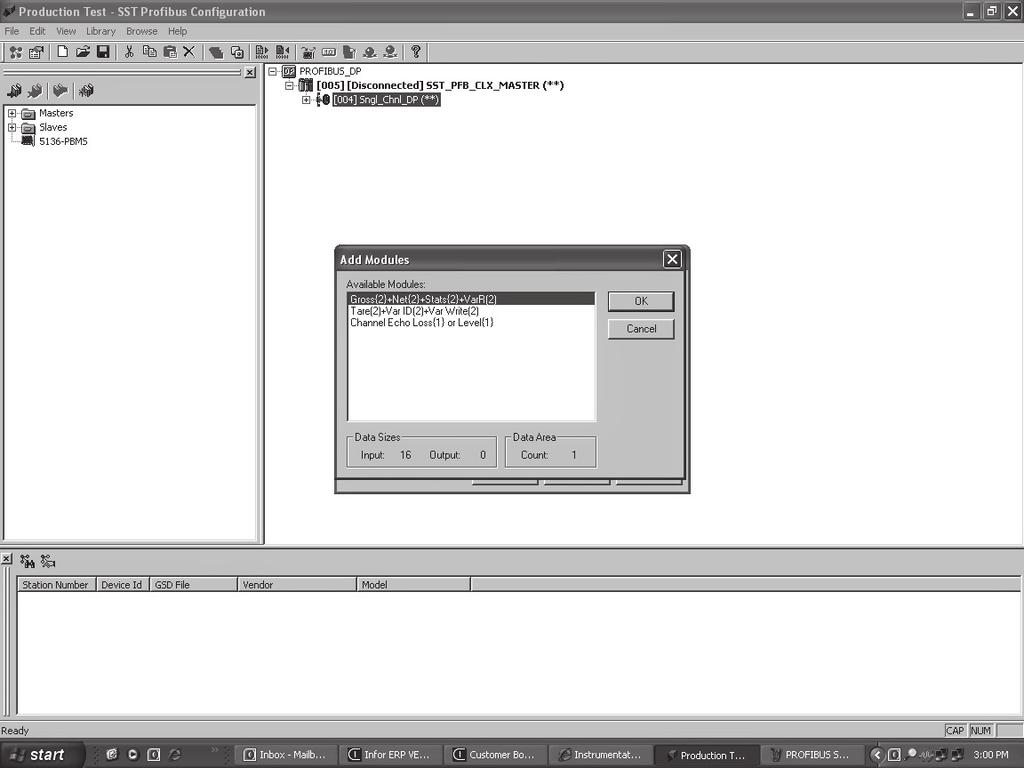
10 6
11 VI. PLC INPUT/OUTPUT CONFIGURATION TABLE At this point weight data and status should be received by the PLC. The PLC should be able to set the required tare command bit in order to force the SVS2000 to tare and read/write a supported variable. Currently there are only two (2) supported variables that can be read/written. Read/write is optional and not required for gross/net values. OUTPUT WORD WORD Tare MSW 2 Tare LSW CH4* CH3* CH2* CH1 3 Read/Write WR RD 4 Variable ID 5 Variable Write MSW * Channels 2-4 only available 6 Variable Write LSW on Weigh II INPUT WORD WORD Gross MSW 2 Gross LSW 3 Net MSW 4 Net LSW 5 Status MSW 6 Status LSW Not Used Not Used Not Used Not Used Format Bits Gross Units Negative Gross/Net Unit Error ADC Error Comm Error Avg or Calibration Error Move More Material Not Used Net Units Negative 7 Variable Read MSW 8 Variable Read LSW To Read A Variable: a. In the Output Word, set Read/Write bit (line 3) to b. In the Output Word, set the Variable ID (line 4) to for Setpoint 1 or for Setpoint 2. Subsequently, the value will be returned in the Input Word, Variable Read (line 8). To Write A Variable: a. In the Output Word, set Read/Write bit (line 3) to FORMAT BITS XXXXXX XXXXXX XXXXXX XXXXX.X XXXX.XX XXX.XXX * Channels 2-4 only available on Weigh II b. In the Output Word, set the Variable ID (line 4) to for Setpoint 1 or for Setpoint 2. c. Add the new input values, in binary, to the Output Word, Variable Write (line 6 or 5 and 6). What is written in line 6 or 5 and 6 will show up on the Input Word in lines 8 or 7 and 8. Invalid values will be ignored. 7
12 VII. troubleshooting Staus indicators are as follows: FOR DEVICENET LED Network Status (NS) Module Status (MS) Off Not on-line or no power to the system. Module not powered Green On-line, one or more connections established Normal Operation Green Flashing On-line, no connections established Auto-baud in progress Red Critical link failure Unrecoverable fault detected Red Flashing Connection timeout Recoverable fault detected Alternating Red/Green Flashing Self-test in progress Self-test in progress FOR ETHERNET/IP LED Network Status (NS) Module Status (MS) Off Not on-line or no power to the system. Module not powered Green On-line, one or more connections established Normal Operation Green Flashing On-line, no connections established No connection Red Duplicate IP address detected Unrecoverable fault detected Red Flashing Connection timeout Recoverable fault detected Alternating Red/Green Flashing Self-test in progress Self-test in progress LED Network Status (LA) Module Status (RA) Off Not on-line or no power to the system. 10 Mps operation Green On-line, one or more connections established 100 Mps operation Green Flashing RX/TX activity NA Red NA NA Red Flashing NA NA Alternating Red/Green Flashing Self-test in progress Self-test in progress FOR PROFIBUS DP There is a single LED on the Profibus Module labeled D3. LED Off Green Green Flashing Red Red Flashing Alternating Red/Green Status Module not powered Node is in Data Exchange mode Node in Clear mode Error in initializing of module Error in configuration of module Self-test in progress 8

13 VIII. BOARD LAYOUT & WIRING SINGLE OPTION CARD INSTALLATION 4-20 ma Output Card or Serial Output Card OPTION CARD INSTALLATION 9

 in the SVS2000 unit. Cable should click into place.")
14 DEVICENET WIRING CONNECTION To To PLC or other DEVICENET peripheral peripheral equipment. equipment. Acceptable cable types are Belden 3084A or equivallent. Acceptable To prevent ground cable loops, types ground are the Belden signal shield 3084A wire only or at equivalent. 0ne end. To prevent ground loops, ground the signal shield wire only at one end. ETHERNET/IP WIRING CONNECTION Plug ethernet cable into ethernet connector/plug (RJ45) in the SVS2000 unit. Cable should click into place. PROFIBUS WIRING CONNECTION Plug Profibus cable into DB9 connector in the SVS2000 unit. Connector should screw into place. 10
15 Notes 11
16 150 Venture Boulevard Spartanburg, SC Tel: (800) Tel: (864) [Local] Fax: (864) All rights reserved. All data subject to change without notice.
Communication settings: Network configuration can be done via the Anybus IP configuration setup tool or via the on board Web server
 SmartLinx EtherNet/IP instruction and use APPLICATION GUIDE Objective: Show the user how to configure and use an EtherNet/IP SmartLinx communication module. AG082415 While every effort was made to verify
Network configuration can be done via the Anybus IP configuration setup tool or via the on board Web server.
 SmartLinx EtherNet/IP instruction and use Objective: Show the user how to configure and use a EtherNet/IP SmartLinx communication module. AG052813 While every effort was made to verify the following information,
G5 Weighing Instrument
 G5 Weighing Instrument Program version 1.4.X Fieldbus Option Manual PM and RM types CONTENTS 1. Introduction... 1-1 General... 1-1 Module installation... 1-2 Ordering information... 1-3 2. Modules...
Table of Contents 1 ABOUT THIS DOCUMENT GENERAL COPYRIGHT INFORMATION TERMS ABOUT THE GATEWAY PRODUCT FUNCTIO
 DeviceNet/PROFIBUS-DP Adapter - User Manual REV 4.0 SiboTech Automation Co., Ltd. Technical Support: +86-21-5102 8348 E-mail:gt@sibotech.net Table of Contents 1 ABOUT THIS DOCUMENT...2 1.1 GENERAL... 2
Quick Start Manual G2-2 Series with Ethernet Interface
 Getting Started This is a brief document designed to quickly get you started setting up your valve manifold with integrated G2-2 series EtherNet/IP communication protocol. 1) Initial Unpacking and Inspection
HI 6500 series Quick Start Guide
 HI 6500 series Quick Start Guide The HI 6500 series are single channel instruments designed to process signals from analog load cells and output stable gross or net weight readings to a display, a PLC
SVS 2000 Signal Processor. Unpacking & Inspection Mounting Wiring Sealing Openings Installing optional PCBs
 SVS 2000 Unpacking & Inspection Mounting Wiring Sealing Openings Installing optional PCBs SVS 2000 Kistler-Morse R GROSS 1 2 3 4 ZERO NET 5 6 7 8 SVS 2000 TARE FUNC 9 ENTER 0 SVS 2000 Default Procedure
Gateway 1400 Reference Manual
 Profibus-DP Gateway 1400 Reference Manual Copyright All Rights Reserved. No part of this document may be copied, reproduced, republished, uploaded, posted, transmitted, distributed, stored in or introduced
CVIC II - CVIL II - CVIR II - MULTICVIL II - Memory Mapping - Manual
 1/36 CVIC II - CVIL II - CVIR II - MULTICVIL II - Memory Mapping - Manual N - Copyright 2011, St Herblain France All rights reserved. Any unauthorized use or copying of the contents or part thereof is
SMARTLINX INTERFACE MODULE
 SMARTLINX INTERFACE MODULE FOR DEVICE NET Instruction Manual PL-583 April 2001 R 33455830 Rev. 1.1 Safety Guidelines Warning notices must be observed to ensure personal safety as well as that of others,
Interface WM : PD
 ふ Interface WM : PD4000301 This is a hazard alert mark. This mark informs you about the operation of the product. Note This manual is subject to change without notice at any time to improve the product.
Characteristics and functioning
 Characteristics and functioning 1/1 enod4-t Characteristics and functioning 216702-C_NU-eNod4T-ETH-E-0314 2/2 enod4-t Characteristics and functioning 216702-C_NU-eNod4T-ETH-E-0314 1 ENOD4 PRODUCT RANGE...
1) Examine exterior of package for signs of damage. Report any damage to shipping carrier.
 Examine exterior of package for signs of damage. Report any damage to shipping carrier.") I P MAC AD D RE S S Getting Started This is a brief document designed to quickly get you started setting up your valve manifold with an integrated Numatics G2-2 Series EtherNet/IP communication node. 1)
I P MAC AD D RE S S Getting Started This is a brief document designed to quickly get you started setting up your valve manifold with an integrated Numatics G2-2 Series EtherNet/IP communication node. 1)
MVS-Modbus Installation and Operation Manual
 MVS-Modbus Installation and Operation Manual CAUTION It is essential that all instructions in this manual be followed precisely to ensure proper operation of the equipment. 97-1125-01 Rev. C Dec 2002 NOTICE
EQ7000. User Manual. Rev 1.00
 EQ7000 User Manual Rev 1.00 www.equustek.com Revision 1.00 February 27, 2009 Contents INTRODUCTION...4 ABOUT THIS MANUAL...4 INTENDED AUDIENCE...4 HARDWARE SPECIFICATIONS...5 PHYSICAL SPECIFICATIONS...5
HI 6600 series Quick Start Guide
 HI 6600 series Quick Start Guide HI 6600 series is a modular system of weight processors that can deliver up to 30 channels of fast, stable, high resolution weight values to PLCs, PACs and DSCs over a
SMARTLINX INTERFACE MODULE
 SMARTLINX INTERFACE MODULE FOR DEVICE NET Instruction Manual December 2001 R Safety Guidelines Warning notices must be observed to ensure personal safety as well as that of others, and to protect the product
# Byrne Rd, Burnaby, BC, V5J 3J1, Canada Phone: or
 EQ7000 User Manual Rev 1.04 www.equustek.com Revision 1.04 Feb 20th, 2017 #286-5489 Byrne Rd, Burnaby, BC, V5J 3J1, Canada Phone: 888-387-3787 or 604-266-8547 www.equustek.com Page 1 Contents INTRODUCTION...4
Kistler-Morse. Systems: KM to KM Signal Processing (inputs) Outputs Operator Interface. KM to PLC/DCS/PC
 Outputs Operator Interface. KM to PLC/DCS/PC") Systems: KM to KM Signal Processing (inputs) Outputs Operator Interface KM to PLC/DCS/PC Outputs Discrete - Setpoint Relay Analog - 4/20 ma Digital Setpoint - On/Off Data Signal wire & common for each
Systems: KM to KM Signal Processing (inputs) Outputs Operator Interface KM to PLC/DCS/PC Outputs Discrete - Setpoint Relay Analog - 4/20 ma Digital Setpoint - On/Off Data Signal wire & common for each
A TCP/IP network CAT 5 cable If the network is faster than 10baseT a switching hub will be needed Static IP address
 Requirements A TCP/IP network CAT 5 cable If the network is faster than 10baseT a switching hub will be needed Static IP address Power Up A Reader with an Ethernet adaptor installed and the network cable
ORB TM 4-20 ma Input Box Installation & Operation Manual
 IOM ORB TM 4-20 ma Input Box Installation & Operation Manual ORB TM 4-20 ma Input Box Installation & Operation Manual CONTENTS I. HANDLING & STORAGE... 1 Inspection and Handling Disposal and Recycling
EtherNet/IP Communications Module
 EtherNet/IP Communications Module M/N RECOMM-ENET Firmware Version 2.xxx Firmware Version 3.xxx Instruction Manual D2-3510-1 The information in this manual is subject to change without notice. Throughout
Interface Module. for Allen-Bradley Remote I/O. Instruction Manual PL-533 May Rev 3.0
 Interface Module for Allen-Bradley Remote I/O Instruction Manual PL-533 May 2000 33455330 Rev 3.0 Ultrasonic level Radar At Milltronics, we endeavour to design equipment that is simple to use and reliable
Installation and Programming Manual
 MUCM SATO Printer Application Manual MUCM SATO Installation and Programming Manual This Manual describes the MUCM application for interfacing a SATO M-8400 barcode printer to an MUCM. Effective: 18 May,
Characteristics and functioning
 Characteristics and functioning 1/27 enod4-c Characteristics and functioning NU-eNod4C-ETH-E-1014_216706-A 1 ENOD4 PRODUCT RANGE... 4 1.1 General presentation... 4 1.2 Versions and options... 4 1.2.1 Versions...
HI 6600 series Quick Start Guide
 HI 6600 series Quick Start Guide HI 6600 series is a modular system of weight processors that can deliver up to 30 channels of fast, stable, high-resolution weight values to PLCs, PACs and DSCs over a
DEFAULT IP ADDRESS
 REAL TIME AUTOMATION 2825 N. Mayfair Rd. Suite 111 Wauwatosa, WI 53222 (414) 453-5100 www.rtaautomation.com EtherNet/IP - DeviceNet Master Gateway MODBUS TCP - DeviceNet Master Gateway Copyright 2007 Real
PROFIBUS Interface WM : PD
 ふ PROFIBUS Interface WM : PD4000303 This is a hazard alert mark. This mark informs you about the operation of the product. Note This manual is subject to change without notice at any time to improve the
G3 Series PROFIBUS DP Technical Manual
 G3 Series PROFIBUS DP Technical Manual Table of Contents G3 Series PROFIBUS DP Technical Manual PAGE About PROFIBUS-DP...3 Overview...3 G3 PROFIBUS-DP Features...3 Cabling and Drop Line Lengths (as defined
Interface Module for Allen-Bradley Remote I/O Instruction Manual PL-533 September 1999
 Interface Module for Allen-Bradley Remote I/O Instruction Manual PL-533 September 1999 33455330 Rev 2.0 Ultrasonic level Radar At Milltronics, we endeavour to design equipment that is simple to use and
IOM Rev. J. ORB TM Inventory Management System Installation & Operation Manual
 IOM ORB TM Inventory Management System Installation & Operation Manual ORB TM Inventory Management System Installation & Operation Manual CONTENTS I. HANDLING AND STORAGE...1 Inspection and Handling Disposal
PROFIBUS DP/CAN Gateway PCA-100. User Manual
 PCA-100 REV 4.0 SiboTech Automation Co., Ltd. Technical Support: 021-5102 8348 E-mail: support@sibotech.net Catalog 1 Introduction... 2 1.1 About This Instruction... 2 1.2 Copyright... 2 1.3 Related Products...
AMCI NX3A1E Specifications Rev 0.0 Resolver PLS Ethernet Module
 Module Overview The AMCI NX3A1E module is a single resolver input programmable limit switch module that is programmed by and communicates on Ethernet. The functionality of the NX3A1E is similar to the
SMARTLINX INTERFACE MODULE
 SMARTLINX INTERFACE MODULE FOR ALLEN-BRADLEY REMOTE I/O Instruction Manual December 2001 R Safety Guidelines Warning notices must be observed to ensure personal safety as well as that of others, and to
Allen-Bradley. PowerFlex DSI Communication Adapters. DeviceNet (22-COMM-D) EtherNet/IP (22-COMM-E) PROFIBUS (22-COMM-P) RS-232 DF1 Module (22-SCM-232)
 EtherNet/IP (22-COMM-E) PROFIBUS (22-COMM-P) RS-232 DF1 Module (22-SCM-232)") Communications PowerFlex DSI Communication Adapters DeviceNet (22-COMM-D) EtherNet/IP (22-COMM-E) PROFIBUS (22-COMM-P) RS-232 DF1 Module (22-SCM-232) Communications 22-COMM-D DeviceNet Adapter The PowerFlex
Communications PowerFlex DSI Communication Adapters DeviceNet (22-COMM-D) EtherNet/IP (22-COMM-E) PROFIBUS (22-COMM-P) RS-232 DF1 Module (22-SCM-232) Communications 22-COMM-D DeviceNet Adapter The PowerFlex
Catalog 1 Product Overview General Important User Information About the Gateway Function Features Tec
 PROFIBUS DP / Modbus TCP Gateway EP-321MP User Manual REV 1.2 Sibotech Automation Co., Ltd Technical Support: 021-5102 8348 E-mail:support@sibotech.net Catalog 1 Product Overview... 4 1.1 General...4 1.2
RC-SV Configuration Guide (Rev 4)
") Kramer Electronics, Ltd. RC-SV Configuration Guide (Rev 4) Software Version 2.1.2.69 Intended for Kramer Technical Personnel or external System Integrators. To check that you have the latest version, go
Kramer Electronics, Ltd. RC-SV Configuration Guide (Rev 4) Software Version 2.1.2.69 Intended for Kramer Technical Personnel or external System Integrators. To check that you have the latest version, go
HI 1734-WS Quick Start Guide
 HI 1734-WS Quick Start Guide HI1734-WS POINT I/O Weigh Scale Module is used for high quality front end signal processing of load cells and load points (strain-gage type sensors) for all types of industrial
Reference Manual. SAI Standard Automation Interface
 Reference Manual Standard Automation Interface Table of Contents 1 Overview 3 1.1 Cyclic data 3 1.2 Acyclic data 3 2 Cyclic Data Layout 4 2.1 Measuring block 4 2.2 Status block 5 2.3 Device to control
QUCM Limitorque Controller
 QUCM Limitorque Valve Controller Application Manual QUCM Limitorque Controller Installation and Programming Manual This Manual describes the QUCM application for interfacing Limitorque Valve Actuators
For the configuration of the I/O-modules in a control system an EDS-file is required. The names of the files are as follows:
 Quick Reference for I/O-modules 0980 ESL 710 and 0980 ESL 711 This quick reference shall help to put the LioN-M I/O-modules 0980 ESL 710 and 0980 ESL 711 with Ethernet/IP interface into operation. It explains
Instruction Manual February smartlinx interface module PROFIBUS-DP
 Instruction Manual February 2003 R smartlinx interface module PROFIBUS-DP Safety Guidelines Warning notices must be observed to ensure personal safety as well as that of others, and to protect the product
4.6 PT8AIIS ISOLATED ANALOG CURRENT INPUTS Description
 4.6 PT8AIIS ISOLATED ANALOG CURRENT INPUTS 4.6.1 Description The PT8AIIS module is an 8 channel isolated current input module. The module uses differential inputs to reduce effects of electrical noise
This document hosted by: 10. OPTIONS
 This document hosted by: www.oldwillknottscales.com 10. OPTIONS The following options are available for the FG series: OP-23 (FG-23) RS-232C serial interface OP-24 (FG-24) RS-232C serial interface and
Installation and Configuration Guide
 Installation and Configuration Guide Trademark Notices Comtrol, NS-Link, and DeviceMaster are trademarks of Comtrol Corporation. Microsoft and Windows are registered trademarks of Microsoft Corporation.
Reference Manual. SAI Standard Automation Interface
 Reference Manual Standard Automation Interface Table of Contents 1 Version History 3 2 Overview 4 2.1 Cyclic data... 4 2.2 Acyclic data... 4 3 Cyclic Data Layout 5 3.1 Measuring block... 5 3.2 Status
BIET EtherNet Interface
 BIET EtherNet Interface Preliminary Release Notes are used to call attention to information that is significant to the understanding and operation of equipment. This BALOGH manual is based on information
User Manual Gateway component for EtherNet/IP
 User Manual Gateway component for EtherNet/IP PR100066 1/7/2016 Table of Contents KUNBUS GmbH Table of Contents 1 General Information... 3 1.1 Disclaimer... 3 1.2 Notes Regarding this User Manual... 4
IPM650 Intelligent Panel-Mount Display
 Quick Start Guide IPM650 Intelligent Panel-Mount Display Sensor Solutions Source Load Torque Pressure Multi Component Calibration Instruments Software www.futek.com Getting Help TECHNICAL SUPPORT For more
Instruction Manual June smartlinx module DEVICENET
 Instruction Manual June 2008 R smartlinx module DEVICENET Safety Guidelines: Warning notices must be observed to ensure personal safety as well as that of others, and to protect the product and the connected
OptiStep Hardware Manual
 OptiStep Hardware Manual Document Revision D4 May 16, 2018 MICROKINETICS CORPORATION 3380 Town Point Drive Suite 330 Kennesaw, GA 30144 Tel: (770) 422-7845 Fax: (770) 422-7854 www.microkinetics.com Table
Data sheet GCM MOD GMM EC.1 Communications module Modbus for GMM EC
 Data sheet GCM MOD GMM EC.1 Communications module Modbus for GMM EC ERP no.: 5206415 GCM MOD GMM EC.1 www.guentner.de Page 2 / 15 Contents 1 GCM MOD GMM EC.1...3 1.1 Functional description...3 1.2 Connections...
MARTLINX INTERFACE MODULE
 SMARTLINX INTERFACE MODULE FOR PROFIBUS-DP Instruction Manual December 2001 R MARTLINX INTERFACE MODULE Safety Guidelines Warning notices must be observed to ensure personal safety as well as that of others,
RTU560 Connections and Settings DIN Rail RTU 560CIG10
 Connections and Settings DIN Rail RTU 560CIG10 Application, characteristics and technical data have to be taken from the hardware data sheet: 560CIG10 1KGT 150 719 Operation The 560CIG10 is a DIN rail
Sure Coat Modular Gun Control System Part C: UCS ProfiBus Interface Card. Customer Product Manual Part B
 Sure Coat Modular Gun Control System Part C: UCS ProfiBus Interface Card Customer Product Manual Issued 4/02 For parts and technical support, call the Industrial Coating Systems Customer Support Center
MAGUIRE G2-ES Configuration Instructions for Ethernet to Serial Converter Model: Moxa NPort 5110 Serial Device Server
 TECHNICAL INSTRUCTIONS MAGUIRE G2-ES Configuration Instructions for Ethernet to Serial Converter Model: Moxa NPort 5110 Serial Device Server This instructional support document is written for the MOXA
Remote I/O ALLEN-BRADLEY Remote I/O Interface for IQ plus 310A and IQ plus 800/810 Indicators
 Remote I/O ALLEN-BRADLEY Remote I/O Interface for IQ plus 310A and IQ plus 800/810 Indicators Version 2.04 Installation and Programming Manual 36254 Contents About This Manual... 1 1.0 Introduction...
Calibration & Connectivity
 Calibration & Connectivity TS-700 Series Digital Indicators This document supplements the User s Guide TS-700 MS TS-700 SS TS-700 WB Full Function/Advanced Function Digital Indicator www.trinerscale.com
Instruction Manual March smartlinx interface module REMOTE I/O
 Instruction Manual March 2004 R smartlinx interface module REMOTE I/O Safety Guidelines Warning notices must be observed to ensure personal safety as well as that of others, and to protect the product
7561-PSD Manual Portable Battery Powered Indicator
 7561-PSD Manual Portable Battery Powered Indicator Lebow Products Inc. 1728 Maplelawn Drive P.O. Box 1089 Troy, Michigan 48084-1089 (800) 803-1164 Phone: (248) 643-0220 FAX: (248) 643-0259 Visit our web
Multi-Function Smart Indicator User Manual
 Multi-Function Smart Indicator User Manual EC30006 Content 1 Notice... 2 2 Specification... 2 3 Main parameter... 3 4 How to fix... 3 5 Port... 4 6 On/Off... 4 7 Charging... 4 8 Display... 5 9 Screen keypad...
Pennsylvania Scale Company Model 400B Battery Powered Digital Indicator Operation & Calibration Manual
 Pennsylvania Scale Company Model 400B Battery Powered Digital Indicator Operation & Calibration Manual Pennsylvania Scale Company 1042 New Holland Avenue Lancaster PA 17601 For online interactive tech
Operating instructions and installation information. METTLER TOLEDO MultiRange Profibus-DP-ID7 field bus card
 T Operating instructions and installation information METTLER TOLEDO MultiRange Profibus-DP-ID7 field bus card Profibus-DP-ID7 Introduction and assembly 1 Introduction and assembly 1.1 Introduction With
FloBoss S600+ Field Upgrade Guide
 Form Number A6299 Part Number D301668X412 February 2011 FloBoss S600+ Field Upgrade Guide Remote Automation Solutions FloBoss S600+ Field Upgrade Guide Revision Tracking Sheet February 2011 This manual
Installation & User Manual
 Contents Installation Instructions 3 Installation Diagrams 4 System Overview 6 Wiring Diagrams 8 Network Diagrams 9 Operation Instructions Fingerprint Enrollment 12 21 Wi-Enterprise Controller www.transmittersolutionssmart.com
RC-SV Configuration Guide Revision 3
 Kramer Electronics, Ltd. RC-SV Configuration Guide Revision 3 Software Version 2.1.2.32 Intended for Kramer Technical Personnel or external System Integrators. To check that you have the latest version,
EtherSeries. EtherSeries CR-2. CR-2-Opto. User s Guide. Revised October 7, 2013 Firmware Version 1.X
 EtherSeries EtherSeries CR-2 & CR-2-Opto User s Guide Revised October 7, 2013 Firmware Version 1.X TABLE OF CONTENTS SECTION 1 - DESCRIPTION... 2 SECTION 2 - SPECIFICATIONS... 4 SECTION 3 - INSTALLATION...
Intech Micro 2300-RO4 analogue input station MODBUS RTU slave application supplementary manual.
 Intech Micro 2300-RO4 analogue input station MODBUS RTU slave application supplementary manual. MODBUS supplementary manual to the 2300-RO4 Installation Guide. The 2300 series stations are designed to
H704-42(H)(E), H704-42/1(H)(E)
(E), H704-42/1(H)(E)") POWER MONITORING INSTALLATION GUIDE H704-42(H)(E), H704-42/1(H)(E) Branch Current Monitor DANGER NOTICE Installer's Specifications General: Operating Temp. Range 0 to 60 C (32 to 140 F) (
POWER MONITORING INSTALLATION GUIDE H704-42(H)(E), H704-42/1(H)(E) Branch Current Monitor DANGER NOTICE Installer's Specifications General: Operating Temp. Range 0 to 60 C (32 to 140 F) (
Connecting SLC Systems as Remote I/O to PLC-5 Processors
 Reference Guide This document combines available PLC and SLC documentation to show you how you can communicate between these two types of systems over the remote I/O link. This information is in addition
CJ Series EtherNet/IP TM Connection Guide. OMRON Corporation NX-series EtherNet/IP Coupler Unit P656-E1-01
 CJ Series EtherNet/IP TM Connection Guide OMRON Corporation NX-series EtherNet/IP Coupler Unit P656-E1-01 About Intellectual Property Rights and Trademarks Microsoft product screen shots reprinted with
Anybus-CC CFW-11. User s Manual. Phone: Fax: Web: -
 Anybus-CC CFW-11 User s Manual Anybus-CC User s Manual Series: CFW-11 Language: English Document Number: 0899.5750 / 06 Publication Date: 09/2013 CONTENTS CONTENTS... 3 ABOUT THE MANUAL... 6 ABBREVIATIONS
Serial Communications Accessories SITRANS RD200/300. Operating Instructions 05/2013 SITRANS
 Serial Communications Accessories SITRANS RD200/300 Operating Instructions 05/2013 SITRANS Siemens Auto SIT SITRANS RD300RANS RD300 Safety Guidelines: Warning notices must be observed to ensure personal
Installation & User Manual V2.08
 YOUR SECURITY IS OUR PRIORITY Other products from GSD Contents Installation Instructions Installation Diagrams System Overview Wiring Diagrams Network Diagrams Operation Instructions Fingerprint Enrollment
Installation OVERVIEW
 Installation OVERVIEW The DEMCO GATE ACCESS CONTROL SYSTEM is designed to operate up to 4 gates, each with an IN KEYPAD and/or an OUT KEYPAD. Each gate is wired as illustrated in the drawing of a "TYPICAL
IND560. Terminal. PLC Interface Manual (05/2009).R05
.R05") IND560 Terminal PLC Interface Manual www.mt.com 72184339 (05/2009).R05 METTLER TOLEDO 2009 No part of this manual may be reproduced or transmitted in any form or by any means, electronic or mechanical,
IND560 Terminal PLC Interface Manual www.mt.com 72184339 (05/2009).R05 METTLER TOLEDO 2009 No part of this manual may be reproduced or transmitted in any form or by any means, electronic or mechanical,
Upgrading an EP/2 to a Lingo SE
 Upgrading an EP/2 to a Lingo SE Introduction This document provides instructions for upgrading a Novar Controls Executive Processor (EP/2) to a Lingo SE. The process involves: Removing the EP/2 electronics
Operating Instructions. Modules Fieldbus
 Operating Instructions Modules Fieldbus Leer Table of Content 1 Introduction... 5 1.1 General... 5 1.2 Compatibility... 6 1.3 Related Documentation... 6 1.4 Internet addresses... 6 2 Functional Overview...
G3 Series EtherNet/IP TM Technical Manual
 G3 Series EtherNet/IP TM Technical Manual Conditions for use of this product G3 Series EtherNet/IP Technical Manual () Numatics G3 Manifold ("the PRODUCT") shall be used in conditions; i) Where any problem,
MGate TM EIP3000 DF1 to EtherNet/IP Gateway User s Manual
 MGate TM EIP3000 DF1 to EtherNet/IP Gateway User s Manual First Edition, June 2009 www.moxa.com/product 2009 Moxa Inc. All rights reserved. Reproduction without permission is prohibited. MGate EIP3000
1. Introduction. Be sure to read the release notes in section 10 before operating the Unit.
 1. Introduction This manual describes the ways of configuring and monitoring the operation of the PROFINET IO Controller CJ1W-PNT Sample Version V0.00 V67.06 V0.00 (Internal release V6.29). Be sure to
2005/2012 Series Profibus DP Technical Manual
 2005/2012 Series Profibus DP Technical Manual LT2005/2012PBTECH-1 04/02 www.numatics.com Table of Contents 2005/2012 Series Profibus DP Technical Manual PAGE About Profibus DP... 3 Overview... 3 G2-2 Profibus-DP
BNI EIP Z016. IP67 Modules, 8 Outputs BNI EIP Z016 BNI EIP Z016 IP67 Modules, 16 Outputs User s Guide
 BNI EIP-202-000-Z016 BNI EIP-202-100-Z016 IP67 Modules, 8 Outputs BNI EIP-206-000-Z016 BNI EIP-206-100-Z016 IP67 Modules, 16 Outputs User s Guide 1 Notes for the user 1.1 About this guide 2 1.2 Structure
Hardy EASY 8 Quick Start & Programming Guide. Function Block Description
 Hardy EASY 8 Quick Start & Programming Guide Section 1: Section 2: Section 3: Wiring Guide Function Block Description Using Function Blocks Section 1: Wiring Guide 1 Excitation + 7 C2+ (PLUS version only)
An ISO 9001 Company. BOP 1KW-MG FIRMWARE RETROFIT KIT
 INSTRUCTION MANUAL 1. DESCRIPTION KEPCO An ISO 9001 Company. BOP 1KW-MG FIRMWARE RETROFIT KIT BOP 1KW-MG RETROFIT KIT 219-0597 Kepco KIT 219-0597 contains the PROMs used to upgrade the firmware for BOP
USER S MANUAL. FX2N-64DNET DeviceNet Interface Block
 USER S MANUAL FX2N-64DNET DeviceNet Interface Block FX2N-64DNET DeviceNet Interface Block Foreword This manual contains text, diagrams and explanations which will guide the reader in the correct installation
Operating Instructions. Modules Fieldbus
 Operating Instructions Modules Fieldbus Leer Table of Content 1 Introduction... 6 1.1 General... 6 1.2 Compatibility... 7 1.3 Related documentation... 7 1.4 Internet addresses... 7 2 Functional Overview...
Intech Micro 2300-A8VI analogue input station MODBUS RTU slave application supplementary manual.
 Intech Micro 2300-A8VI analogue input station MODBUS RTU slave application supplementary manual. MODBUS supplementary manual to the 2300-A8VI Installation Guide. The 2300 series stations are designed to
1) Examine exterior of package for signs of damage. Report any damage to shipping carrier.
 Examine exterior of package for signs of damage. Report any damage to shipping carrier.") Getting Started This is a brief document designed to quickly get you started setting up your 2002 Series valve manifold with integrated Numatics G2-1\2 Profibus-DP communication protocol. Please note that
Getting Started This is a brief document designed to quickly get you started setting up your 2002 Series valve manifold with integrated Numatics G2-1\2 Profibus-DP communication protocol. Please note that
Rev Cutler-Hammer Smart Breaker Panel Control Manual
 026-70 Rev 0 6-0-03 Cutler-Hammer Smart Breaker Panel Control Manual 640 Airport Road, Suite 04 Kennesaw, GA 3044 Phone: (770) 425-2724 Fax: (770) 425-939 ALL RIGHTS RESERVED. The information contained
2562 QUICK START GUIDE
 2562 QUICK START GUIDE CTI P/Ns: 2562 Quick Start Guide: 062-00348-010 2562 Installation and Operation Guide: 062-00332-011 Summary: The 2562 is designed to translate a digital word from the programmable
12.3 Fieldbus I/O Board
 12.3 Fieldbus I/O Board 12.3.1 Overview of Fieldbus I/O The Fieldbus I/O option is an option to add fieldbus slave function (DeviceNet, PROFIBUS-DP, CC-Link, EtherNet/IP) to the robot Controller. A fieldbus
Document Number: Rev. B
 User Guide Trademark Notices Microsoft and Windows are registered trademarks of Microsoft Corporation. Other product names mentioned herein may be trademarks and/or registered trademarks of their respective
Canlan INSTALLATION MANUAL
 Canlan INSTALLATION MANUAL August 2014 Table of Contents Introduction... 4 Overview... 5 RJ45 Connector and Status LEDs... 5 Power Input... 6 RS232 / RS485 Connectors... 7 Installing the Canlan Software...
T1K MODBUS Base Controller Specifications
 Base Controller 1 2 In This Chapter.... Base Controller Setting the DIP Switches Setting the Rotary Address Switches Port Pin out and Wiring RJ12 Serial Port Pin out and Wiring 2 2 Base Controller General
The following simple procedures should be performed prior to testing the 289H M relay card:
 289H M LSS Installation & Operations Manual Start Up & Test Procedures Chapter 5 INTRODUCTION The information in this section of the manual provides the step by step procedures for conducting any testing
FNL Modbus TCP Interface
 FNL Modbus TCP Interface Users Manual V0.1 17.06.2009 Project No.: 5304 Doc-ID.: FNL Modbus TCP Interface-UM-V0.1 Status: Released COMSOFT d:\windoc\icp\doku\hw\fnl\modbus tcp\version_0.1\fnl_modbus_tcp_e.doc
Installation & Operation Guide
 Installation & Operation Guide (Shown with optional Override Board Cover) KMD-5831 Programmable Loop Controller PLC-28 Direct Digital Controller 902-019-04B 1 Introduction This section provides a brief
User Manual. PowerFlex 25-COMM-E2P Dual-Port EtherNet/IP Adapter
 User Manual PowerFlex Dual-Port EtherNet/IP Adapter Chapter 1 Getting Started The Dual-port EtherNet/IP adapter is a communication option intended for installation into a PowerFlex 520-series drive. The
CJ Series IO-Link Connection Guide (EtherNet/IP TM Host Communications) OMRON Corporation Proximity Sensor (E2E-series IO-Link)
 OMRON Corporation Proximity Sensor (E2E-series IO-Link)") CJ Series IO-Link Connection Guide (EtherNet/IP TM Host Communications) OMRON Corporation Proximity Sensor (E2E-series IO-Link) [IO-Link Master Unit] OMRON Corporation NX-series IO-Link Master Unit (NX-ILM[][][])
CJ Series IO-Link Connection Guide (EtherNet/IP TM Host Communications) OMRON Corporation Proximity Sensor (E2E-series IO-Link) [IO-Link Master Unit] OMRON Corporation NX-series IO-Link Master Unit (NX-ILM[][][])