CS 250 VLSI Design Lecture 11 Design Verification
|
|
|
- Shona Jordan
- 5 years ago
- Views:
Transcription
1
2
3 CS 250 VLSI Design Lecture 11 Design Verification John Wawrzynek Jonathan Bachrach Krste Asanović John Lazzaro TA: Rimas Avizienis www-inst.eecs.berkeley.edu/~cs250/

4 IBM Power Million Transistors A complex design... First silicon booted AIX & Linux, on a 16-die system. 96% of all bugs were caught before first tape-out. How???
5 Three main components... (1) Specify chip behavior at the RTL level, and comprehensively simulate it. (3) Technology layer: do the the electrons implement the RTL, at speed and power? (2) Use formal verification to show equivalence between VHDL RTL and circuit schematic RTL. Today, we focus on (1).
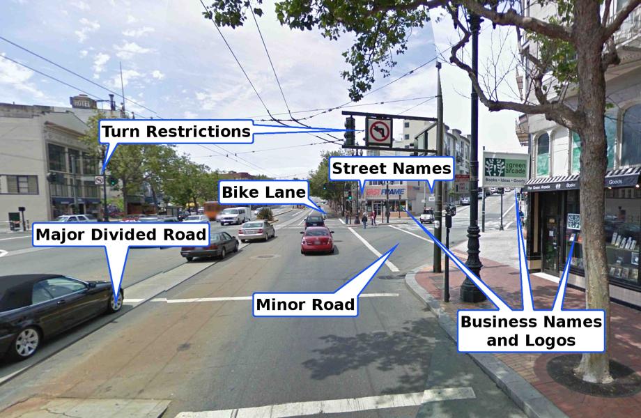
6 But our project isn t a CPU! Camera input frames dx/dt dy/dt Hardwired Optic Flow Algorithm Large SRAMs for image data, etc. Input movie streams == CPU test programs Both are history-dependent. Both exercise a small fraction of state space.
7 Today: Processor Design Verification Making a test plan Unit techniques State machine How to write test programs
8 Lecture Focus: Functional Design Test Not manufacturing tests... goal The design correctly executes programs written in the Instruction Set Architecture Correct == meets the Architect s Contract Intel XScale ARM Pipeline, IEEE Journal of Solid State Circuits, 36:11, November 2001
9 Architect s Contract with the Programmer To the program, it appears that instructions execute in the correct order defined by the ISA. As each instruction completes, the architected machine state appears to the program to obey the ISA. What the machine actually does is up to the hardware designers, as long as the contract is kept. Also: The data sheet contract with board or SOC designer.
10 When programmer s contract is broken... Testing our financial trading system, we found a case where our software would get a bad calculation. Once a week or so. Eventually, the problem turned out to be a failure in a CPU cache line refresh. This was a hardware design fault in the PC. The test suite included running for two weeks at maximum update rate without error, so this bug was found. Eric Ulevik

11 A 475M$ Bug
12 Three models (at least) to cross-check. The contract specification The answer (correct, we hope). Simulates the ISA model in C. Fast. Better: two models coded independently. The Chisel RTL model Logical semantics of the Chisel model we will use to create gates. Runs on a software simulator or FPGA hardware. Chip-level schematic RTL Catch synthesis bugs. Formally verify netlist against Chisel RTL. Also used for timing and power. Where do bugs come from?
13 Where bugs come from (a partial list)... The contract is wrong. You understand the contract, create a design that correctly implements it, write correct Chisel for the design... The contract is misread. Your design is a correct implementation of what you think the contract means... but you misunderstand the contract. Conceptual error in design. You understand the contract, but devise an incorrect implementation of it... Chisel coding errors. You express your correct design idea in Chisel.. with incorrect Chisel semantics. Also: CAD-related errors. Example: Chisel-to-Verilog translation errors.

14 For your project: X dx/dt Do bit-by-bit compare of output movie from contract and Chisel. dy/dt y
15 Optic Flow Contract
16 Computing Specify all details of fixed-point arithmetic, so that bit-accurate hardware is efficient. y x t
17 Computing Be sure to specify what happens in the first frame (i.e. what happens on reset) y x t
18 (2) How to do optimization... Think carefully about commutativity, associativity, overflow and underflow, pros and cons of saturating arithmetic, etc. Reminder: All of your implementations need to be bit-accurate with your contract model... so define it carefully!
19 Four Types of Testing
20 Big Bang: Complete Processor Testing Top-down complete how it works Assemble the complete. Execute test program suite on the. Bottom-up Check results. Checks contract model against Chisel RTL. Test suite runs the gamut from 1-line programs to boot the OS.
21 Methodical Approach: Unit Testing Top-down complete unit how it works Remove a block from the design. Test it in isolation against specification. Bottom-up Requires writing a bug-free contract model for the unit.
22 Climbing the Hierarchy: Multi-unit Testing Top-down complete multi-unit unit how it works Remove connected blocks from design. Test in isolation against specification. Bottom-up Choice of partition determines if test is eye-opening or a waste of time
23 Processor Testing with Self-Checking Units Top-down how it works complete with self-checks multi-unit unit Bottom-up Add self-checking to units Perform complete Self-checks are unit tests built into CPU, that generate the right answer on the fly. Slower to simulate.
24 Testing: Verification vs. Diagnostics Top-down complete with self-checks multi-unit unit Bottom-up Verification: A yes/no answer to the question Does the have one more bug? Diagnostics: Clues to help find and fix the bug. Diagnosis of bugs found during complete is hard...
25 CPU program diagnosis is tricky... Observation: On a buggy CPU model, the correctness of every executed instruction is suspect. Consequence: One needs to verify the correctness of instructions that surround the suspected buggy instruction. Depends on: (1) number of instructions in flight in the machine, and (2) lifetime of non-architected state (may be indefinite ).
26
27 State observability and controllability Top-down complete with self-checks multi-unit unit Bottom-up Observability: Does my model expose the state I need to diagnose the bug? Controllability: Does my model support changing the state value I need to change to diagnose the bug? Support!= yes, just rewrite the model code!
28 Writing a Test Plan
29 The timeline... Top-down complete Plan in advance what tests to do when... Epoch 1 Epoch 2 Epoch 3 Epoch 4 with self-checks multi-unit Time unit Bottom-up assembly complete correctly executes single instructions correctly executes short programs
30 An example test plan... Top-down complete with self-checks multi-unit Epoch 1 Epoch 2 Epoch 3 Epoch 4 unit early multi unit later with self-checks multi-unit unit diagnostics with self-checks multi-unit unit diagnostics complete verification with self-checks diagnostics unit Bottom-up assembly complete correctly executes single instructions correctly executes short programs Time
31 Unit Testing
32 Combinational Unit Testing: 3-bit Adder Cin Number of input bits? 7 A Sum Total number of possible input values? 2 7 = 128 B 3 Just test them all... Cout Apply test vectors 0,1, to inputs. 100% input space coverage Exhaustive
33 Combinational Unit Testing: 32-bit Adder Cin Number of input bits? 65 A Sum Total number of possible input values? 2 65 = 3.689e+19 B 32 Cout Just test them all? Exhaustive does not scale. Combinatorial explosion!
34 Test Approach 1: Random Vectors Cin how it works A B Sum Apply random A, B, Cin to adder. Check Sum, Cout. Cout When to stop? Bug curve. Bug Rate Bugs found per minute of Time

35
36 Test Approach 2: Directed Vectors A B Cin + Directed random Sum how it works Hand-craft test vectors to cover corner cases A == B == Cin == 0 Cout Black-box : Corner cases based on functional properties. Clear-box : Corner cases based on unit internal structure.

37

38
39 State Machine Testing CPU design examples DRAM controller state machines Cache control state machines Branch prediction state machines
40 Testing State Machines: Break Feedback Rst Change Next State Combinational Logic D Q R D Q G D Q Y Isolate Next State logic. Test as a combinational unit. Easier with certain HDL coding styles...
41 Testing State Machines: Arc Coverage Rst == 1 Change == 1 R Y G R Y G Change == Change == 1 R Y G Force machine into each state. Test behavior of each arc. Intractable for state machines with high edge density...
42 Regression Testing Or, how to find the last bug...
43 Writing complete CPU test programs Top-down complete with self-checks Single instructions with directed-random field values. Epoch 1 Epoch 2 Epoch 3 Epoch 4 with self-checks White-box Instructions-inflight sized programs that stress design. with self-checks complete multi-unit Time unit Bottom-up assembly complete correctly executes single instructions correctly executes short programs Tests that stress long-lived non-architected state. Regression : re-run subsets of the test library, and then the entire library, after a fix.

44 Formal Verification: How does it work? Cadence Labs + EECS Adjunct Prof. Verity - a Formal Verification Program for Custom CMOS Circuits Andreas Kuehlmann Arvind Srinivasan David P. LaPotin Boolean Equivalence Checking. How can you show two RTL descriptions are equivalent using static techniques? We begin by formally defining the problem...
45 The formal problem statement... Verilog RTL State Machine C A : Combinational logic. S A : Flip-flops. Question: If we initialize flip-flops appropriately... x x A FSM A C A y A z A z A S A Clk Reset A brief sketch of how the tool goes about answering the question... c For any sequence of input vectors Xo, X1,... C B : Combinational logic. S B : Flip-flops. Schematic State Machine B x FSM B z B C B S B Clk Reset z B B y Will C ever be 1? If no, the Verilog and schematic RTLs are Booleanequivalent.
46 FSM Equivalence: A two-step algorithm (1) Flip-flop equivalence. We assume we can find all flip-flops in RTL for each FSM. If the FSMs do not have the same number of flip-flops, FSMs not EQ. x x A FSM A C A y A z A z A S A Clk Reset (2) Prove C A = C B. Like proving DeMorgan s theorem for a homework assignment... an exercise in symbolic manipulation. c Otherwise, run an algorithm to reorder S A (and thus C A ) to match S B. Trivial solution: the user names the flip-flops. But modern tools can do it automatically. B x FSM B z B C B S B Clk Reset z B B y But the symbols are manipulated by a computer program... and the functions are very large! Rocket science would start here...
47 Conclusion -- Testing Processors" Bottom-up test for diagnosis, top-down test for verification. Unit : avoiding combinatorial explosions. Complete CPU tests: write programs that stress the hard parts of the design. Make your plan early! After the break: Chisel tips.
48 Next Week: Transition to Project Mode
CS 250! VLSI System Design
 CS 250! VLSI System Design Lecture 6 Design Verification 2014 09-16! Professor Jonathan Bachrach! slides by John Lazzaro TA: Colin Schmidt www-inst.eecs.berkeley.edu/~cs250/ CS 250 L6: Design Verification
CS 152 Computer Architecture and Engineering
 CS 152 Computer Architecture and Engineering Lecture 4 Testing Processors 2005-1-27 John Lazzaro (www.cs.berkeley.edu/~lazzaro) TAs: Ted Hong and David Marquardt www-inst.eecs.berkeley.edu/~cs152/ Last
CS 152 Computer Architecture and Engineering Lecture 1 Single Cycle Design
 CS 152 Computer Architecture and Engineering Lecture 1 Single Cycle Design 2014-1-21 John Lazzaro (not a prof - John is always OK) TA: Eric Love www-inst.eecs.berkeley.edu/~cs152/ Play: 1 Today s lecture
Digital Design Methodology
 Digital Design Methodology Prof. Soo-Ik Chae Digital System Designs and Practices Using Verilog HDL and FPGAs @ 2008, John Wiley 1-1 Digital Design Methodology (Added) Design Methodology Design Specification
Lab. Course Goals. Topics. What is VLSI design? What is an integrated circuit? VLSI Design Cycle. VLSI Design Automation
 Course Goals Lab Understand key components in VLSI designs Become familiar with design tools (Cadence) Understand design flows Understand behavioral, structural, and physical specifications Be able to
CS 152 Computer Architecture and Engineering
 CS 152 Computer Architecture and Engineering Lecture 4 Testing and Teamwork 2005-9-8 John Lazzaro (www.cs.berkeley.edu/~lazzaro) Congrats on Lab 1! TAs: David Marquardt and Udam Saini www-inst.eecs.berkeley.edu/~cs152/
EECS150 - Digital Design Lecture 6 - Logic Simulation
 EECS150 - Digital Design Lecture 6 - Logic Simulation Sep. 17, 013 Prof. Ronald Fearing Electrical Engineering and Computer Sciences University of California, Berkeley (slides courtesy of Prof. John Wawrzynek)
Digital System Design Lecture 2: Design. Amir Masoud Gharehbaghi
 Digital System Design Lecture 2: Design Amir Masoud Gharehbaghi amgh@mehr.sharif.edu Table of Contents Design Methodologies Overview of IC Design Flow Hardware Description Languages Brief History of HDLs
Hardware Design Environments. Dr. Mahdi Abbasi Computer Engineering Department Bu-Ali Sina University
 Hardware Design Environments Dr. Mahdi Abbasi Computer Engineering Department Bu-Ali Sina University Outline Welcome to COE 405 Digital System Design Design Domains and Levels of Abstractions Synthesis
DIGITAL DESIGN TECHNOLOGY & TECHNIQUES
 DIGITAL DESIGN TECHNOLOGY & TECHNIQUES CAD for ASIC Design 1 INTEGRATED CIRCUITS (IC) An integrated circuit (IC) consists complex electronic circuitries and their interconnections. William Shockley et
Digital Design Methodology (Revisited) Design Methodology: Big Picture
 Design Methodology: Big Picture") Digital Design Methodology (Revisited) Design Methodology Design Specification Verification Synthesis Technology Options Full Custom VLSI Standard Cell ASIC FPGA CS 150 Fall 2005 - Lec #25 Design Methodology
Digital Design Methodology (Revisited) Design Methodology Design Specification Verification Synthesis Technology Options Full Custom VLSI Standard Cell ASIC FPGA CS 150 Fall 2005 - Lec #25 Design Methodology
CS2204 DIGITAL LOGIC & STATE MACHINE DESIGN FALL 2005
 CS2204 DIGITAL LOGIC & STATE MACHINE DESIGN FALL 2005 AN INTRODUCTION TO DIGITAL SYSTEMS AND THE PPM PROJECT 1. Introduction A digital system consists of digital circuits. It performs sequences of simple
FPGA Design Flow 1. All About FPGA
 FPGA Design Flow 1 In this part of tutorial we are going to have a short intro on FPGA design flow. A simplified version of FPGA design flow is given in the flowing diagram. FPGA Design Flow 2 FPGA_Design_FLOW
Outline. EECS Components and Design Techniques for Digital Systems. Lec 11 Putting it all together Where are we now?
 Outline EECS 5 - Components and Design Techniques for Digital Systems Lec Putting it all together -5-4 David Culler Electrical Engineering and Computer Sciences University of California Berkeley Top-to-bottom
Hardware Modeling using Verilog Prof. Indranil Sengupta Department of Computer Science and Engineering Indian Institute of Technology, Kharagpur
 Hardware Modeling using Verilog Prof. Indranil Sengupta Department of Computer Science and Engineering Indian Institute of Technology, Kharagpur Lecture 01 Introduction Welcome to the course on Hardware
SP3Q.3. What makes it a good idea to put CRC computation and error-correcting code computation into custom hardware?
 Part II CST: SoC D/M: Quick exercises S3-S4 (examples sheet) Feb 2018 (rev a). This sheet contains short exercises for quick revision. Please also look at past exam questions and/or try some of the longer
EECS150 - Digital Design Lecture 4 - Verilog Introduction. Outline
 EECS150 - Digital Design Lecture 4 - Verilog Introduction Feb 3, 2009 John Wawrzynek Spring 2009 EECS150 - Lec05-Verilog Page 1 Outline Background and History of Hardware Description Brief Introduction
EECS150 - Digital Design Lecture 7 - Computer Aided Design (CAD) - Part II (Logic Simulation) Finite State Machine Review
 - Part II (Logic Simulation) Finite State Machine Review") EECS150 - Digital Design Lecture 7 - Computer Aided Design (CAD) - Part II (Logic Simulation) Feb 9, 2010 John Wawrzynek Spring 2010 EECS150 - Lec7-CAD2 Page 1 Finite State Machine Review State Transition
EECS150 - Digital Design Lecture 7 - Computer Aided Design (CAD) - Part II (Logic Simulation) Feb 9, 2010 John Wawrzynek Spring 2010 EECS150 - Lec7-CAD2 Page 1 Finite State Machine Review State Transition
Logic Synthesis. EECS150 - Digital Design Lecture 6 - Synthesis
 Logic Synthesis Verilog and VHDL started out as simulation languages, but quickly people wrote programs to automatically convert Verilog code into low-level circuit descriptions (netlists). EECS150 - Digital
CS/ECE 5780/6780: Embedded System Design
 CS/ECE 5780/6780: Embedded System Design John Regehr Lecture 18: Introduction to Verification What is verification? Verification: A process that determines if the design conforms to the specification.
One and a half hours. Section A is COMPULSORY UNIVERSITY OF MANCHESTER SCHOOL OF COMPUTER SCIENCE
 One and a half hours Section A is COMPULSORY UNIVERSITY OF MANCHESTER SCHOOL OF COMPUTER SCIENCE Fundamentals of Computer Engineering Date: Thursday 21st January 2016 Time: 14:00-15:30 Answer BOTH Questions
EECS150 - Digital Design Lecture 5 - Verilog Logic Synthesis
 EECS150 - Digital Design Lecture 5 - Verilog Logic Synthesis Jan 31, 2012 John Wawrzynek Spring 2012 EECS150 - Lec05-verilog_synth Page 1 Outline Quick review of essentials of state elements Finite State
Lecture #1: Introduction
 Lecture #1: Introduction Kunle Olukotun Stanford EE183 January 8, 20023 What is EE183? EE183 is continuation of EE121 Digital Logic Design is a a minute to learn, a lifetime to master Programmable logic
Don t expect to be able to write and debug your code during the lab session.
 EECS150 Spring 2002 Lab 4 Verilog Simulation Mapping UNIVERSITY OF CALIFORNIA AT BERKELEY COLLEGE OF ENGINEERING DEPARTMENT OF ELECTRICAL ENGINEERING AND COMPUTER SCIENCE Lab 4 Verilog Simulation Mapping
ECE 587 Hardware/Software Co-Design Lecture 11 Verification I
 ECE 587 Hardware/Software Co-Design Spring 2018 1/23 ECE 587 Hardware/Software Co-Design Lecture 11 Verification I Professor Jia Wang Department of Electrical and Computer Engineering Illinois Institute
CS250 VLSI Systems Design Lecture 8: Introduction to Hardware Design Patterns
 CS250 VLSI Systems Design Lecture 8: Introduction to Hardware Design Patterns John Wawrzynek, Jonathan Bachrach, with Krste Asanovic, John Lazzaro and Rimas Avizienis (TA) UC Berkeley Fall 2012 Lecture
Programmable Logic Devices II
 São José February 2015 Prof. Hoeller, Prof. Moecke (http://www.sj.ifsc.edu.br) 1 / 28 Lecture 01: Complexity Management and the Design of Complex Digital Systems Prof. Arliones Hoeller arliones.hoeller@ifsc.edu.br
Chapter 1 Overview of Digital Systems Design
 Chapter 1 Overview of Digital Systems Design SKEE2263 Digital Systems Mun im/ismahani/izam {munim@utm.my,e-izam@utm.my,ismahani@fke.utm.my} February 8, 2017 Why Digital Design? Many times, microcontrollers
Hardware Design Verification: Simulation and Formal Method-Based Approaches William K Lam Prentice Hall Modern Semiconductor Design Series
 Design Verification An Introduction Main References Hardware Design Verification: Simulation and Formal Method-Based Approaches William K Lam Prentice Hall Modern Semiconductor Design Series A Roadmap
EECS Components and Design Techniques for Digital Systems. Lec 20 RTL Design Optimization 11/6/2007
 EECS 5 - Components and Design Techniques for Digital Systems Lec 2 RTL Design Optimization /6/27 Shauki Elassaad Electrical Engineering and Computer Sciences University of California, Berkeley Slides
An Introduction to Programmable Logic
 Outline An Introduction to Programmable Logic 3 November 24 Transistors Logic Gates CPLD Architectures FPGA Architectures Device Considerations Soft Core Processors Design Example Quiz Semiconductors Semiconductor
Administrivia. ECE/CS 5780/6780: Embedded System Design. Acknowledgements. What is verification?
 Administrivia ECE/CS 5780/6780: Embedded System Design Scott R. Little Lab 8 status report. Set SCIBD = 52; (The Mclk rate is 16 MHz.) Lecture 18: Introduction to Hardware Verification Scott R. Little
EE 466/586 VLSI Design. Partha Pande School of EECS Washington State University
 EE 466/586 VLSI Design Partha Pande School of EECS Washington State University pande@eecs.wsu.edu Lecture 18 Implementation Methods The Design Productivity Challenge Logic Transistors per Chip (K) 10,000,000.10m
What is Verilog HDL? Lecture 1: Verilog HDL Introduction. Basic Design Methodology. What is VHDL? Requirements
 What is Verilog HDL? Lecture 1: Verilog HDL Introduction Verilog Hardware Description Language(HDL)? A high-level computer language can model, represent and simulate digital design Hardware concurrency
Two HDLs used today VHDL. Why VHDL? Introduction to Structured VLSI Design
 Two HDLs used today Introduction to Structured VLSI Design VHDL I VHDL and Verilog Syntax and ``appearance'' of the two languages are very different Capabilities and scopes are quite similar Both are industrial
Design Methodologies and Tools. Full-Custom Design
 Design Methodologies and Tools Design styles Full-custom design Standard-cell design Programmable logic Gate arrays and field-programmable gate arrays (FPGAs) Sea of gates System-on-a-chip (embedded cores)
COMP12111 Fundamentals of Computer Engineering Paul Nutter Vasilis Pavlidis Comments
 Fundamentals of Computer Engineering Paul Nutter Vasilis Pavlidis Comments Please see the attached report. 12 February 2016 Page 2 of 7 Exam Feedback 2015/16 Q1 set by Paul Nutter Q2 set by Vasilis Pavlidis
ECE 2300 Digital Logic & Computer Organization. More Sequential Logic Verilog
 ECE 2300 Digital Logic & Computer Organization Spring 2018 More Sequential Logic Verilog Lecture 7: 1 Announcements HW3 will be posted tonight Prelim 1 Thursday March 1, in class Coverage: Lectures 1~7
DESIGN STRATEGIES & TOOLS UTILIZED
 CHAPTER 7 DESIGN STRATEGIES & TOOLS UTILIZED 7-1. Field Programmable Gate Array The internal architecture of an FPGA consist of several uncommitted logic blocks in which the design is to be encoded. The
TOPIC : Verilog Synthesis examples. Module 4.3 : Verilog synthesis
 TOPIC : Verilog Synthesis examples Module 4.3 : Verilog synthesis Example : 4-bit magnitude comptarator Discuss synthesis of a 4-bit magnitude comparator to understand each step in the synthesis flow.
SoC Verification Methodology. Prof. Chien-Nan Liu TEL: ext:
 SoC Verification Methodology Prof. Chien-Nan Liu TEL: 03-4227151 ext:4534 Email: jimmy@ee.ncu.edu.tw 1 Outline l Verification Overview l Verification Strategies l Tools for Verification l SoC Verification
VHDL. VHDL History. Why VHDL? Introduction to Structured VLSI Design. Very High Speed Integrated Circuit (VHSIC) Hardware Description Language
 Hardware Description Language") VHDL Introduction to Structured VLSI Design VHDL I Very High Speed Integrated Circuit (VHSIC) Hardware Description Language Joachim Rodrigues A Technology Independent, Standard Hardware description Language
VHDL Introduction to Structured VLSI Design VHDL I Very High Speed Integrated Circuit (VHSIC) Hardware Description Language Joachim Rodrigues A Technology Independent, Standard Hardware description Language
ADVANCED DIGITAL IC DESIGN. Digital Verification Basic Concepts
 1 ADVANCED DIGITAL IC DESIGN (SESSION 6) Digital Verification Basic Concepts Need for Verification 2 Exponential increase in the complexity of ASIC implies need for sophisticated verification methods to
Functional Programming in Hardware Design
 Functional Programming in Hardware Design Tomasz Wegrzanowski Saarland University Tomasz.Wegrzanowski@gmail.com 1 Introduction According to the Moore s law, hardware complexity grows exponentially, doubling
Advanced VLSI Design Prof. Virendra K. Singh Department of Electrical Engineering Indian Institute of Technology Bombay
 Advanced VLSI Design Prof. Virendra K. Singh Department of Electrical Engineering Indian Institute of Technology Bombay Lecture 40 VLSI Design Verification: An Introduction Hello. Welcome to the advance
Choosing an Intellectual Property Core
 Choosing an Intellectual Property Core MIPS Technologies, Inc. June 2002 One of the most important product development decisions facing SOC designers today is choosing an intellectual property (IP) core.
Logic Verification 13-1
 Logic Verification 13-1 Verification The goal of verification To ensure 100% correct in functionality and timing Spend 50 ~ 70% of time to verify a design Functional verification Simulation Formal proof
VLSI Test Technology and Reliability (ET4076)
") VLSI Test Technology and Reliability (ET4076) Lecture 4(part 2) Testability Measurements (Chapter 6) Said Hamdioui Computer Engineering Lab Delft University of Technology 2009-2010 1 Previous lecture What
VLSI Test Technology and Reliability (ET4076) Lecture 4(part 2) Testability Measurements (Chapter 6) Said Hamdioui Computer Engineering Lab Delft University of Technology 2009-2010 1 Previous lecture What
Lecture (05) Boolean Algebra and Logic Gates
 Boolean Algebra and Logic Gates") Lecture (05) Boolean Algebra and Logic Gates By: Dr. Ahmed ElShafee ١ Minterms and Maxterms consider two binary variables x and y combined with an AND operation. Since eachv ariable may appear in either
Lecture (05) Boolean Algebra and Logic Gates By: Dr. Ahmed ElShafee ١ Minterms and Maxterms consider two binary variables x and y combined with an AND operation. Since eachv ariable may appear in either
Lab 6 Debugging. Objective. Introduction. Prelab
 UNIVERSITY OF CALIFORNIA AT BERKELEY COLLEGE OF ENGINEERING DEPARTMENT OF ELECTRICAL ENGINEERING AND COMPUTER SCIENCE Lab 6 Debugging Objective You will explore several techniques for debugging a digital
FPGA for Complex System Implementation. National Chiao Tung University Chun-Jen Tsai 04/14/2011
 FPGA for Complex System Implementation National Chiao Tung University Chun-Jen Tsai 04/14/2011 About FPGA FPGA was invented by Ross Freeman in 1989 SRAM-based FPGA properties Standard parts Allowing multi-level
EECS150 - Digital Design Lecture 10 Logic Synthesis
 EECS150 - Digital Design Lecture 10 Logic Synthesis September 26, 2002 John Wawrzynek Fall 2002 EECS150 Lec10-synthesis Page 1 Logic Synthesis Verilog and VHDL stated out as simulation languages, but quickly
Chapter 6 Objectives
 Chapter 6 Memory Chapter 6 Objectives Basic memory concepts, such as RAM and the various memory devices Master the concepts of hierarchical memory organization. Understand how each level of memory contributes
Multi Cycle Implementation Scheme for 8 bit Microprocessor by VHDL
 Multi Cycle Implementation Scheme for 8 bit Microprocessor by VHDL Sharmin Abdullah, Nusrat Sharmin, Nafisha Alam Department of Electrical & Electronic Engineering Ahsanullah University of Science & Technology
EECS150 - Digital Design Lecture 10 Logic Synthesis
 EECS150 - Digital Design Lecture 10 Logic Synthesis February 13, 2003 John Wawrzynek Spring 2003 EECS150 Lec8-synthesis Page 1 Logic Synthesis Verilog and VHDL started out as simulation languages, but
Overview. CSE372 Digital Systems Organization and Design Lab. Hardware CAD. Two Types of Chips
 Overview CSE372 Digital Systems Organization and Design Lab Prof. Milo Martin Unit 5: Hardware Synthesis CAD (Computer Aided Design) Use computers to design computers Virtuous cycle Architectural-level,
EECS150: Lab 3, Verilog Synthesis & FSMs
 EECS150: Lab 3, Verilog Synthesis & FSMs UC Berkeley College of Engineering Department of Electrical Engineering and Computer Science February 11, 2009 1 Time Table ASSIGNED DUE Friday, Febuary 6 th Week
101-1 Under-Graduate Project Digital IC Design Flow
 101-1 Under-Graduate Project Digital IC Design Flow Speaker: Ming-Chun Hsiao Adviser: Prof. An-Yeu Wu Date: 2012/9/25 ACCESS IC LAB Outline Introduction to Integrated Circuit IC Design Flow Verilog HDL
EECS150 - Digital Design Lecture 20 - Finite State Machines Revisited
 EECS150 - Digital Design Lecture 20 - Finite State Machines Revisited April 2, 2009 John Wawrzynek Spring 2009 EECS150 - Lec20-fsm Page 1 Finite State Machines (FSMs) FSM circuits are a type of sequential
EEL 4783: HDL in Digital System Design
 EEL 4783: HDL in Digital System Design Lecture 15: Logic Synthesis with Verilog Prof. Mingjie Lin 1 Verilog Synthesis Synthesis vs. Compilation Descriptions mapped to hardware Verilog design patterns for
CS250 VLSI Systems Design Lecture 9: Memory
 CS250 VLSI Systems esign Lecture 9: Memory John Wawrzynek, Jonathan Bachrach, with Krste Asanovic, John Lazzaro and Rimas Avizienis (TA) UC Berkeley Fall 2012 CMOS Bistable Flip State 1 0 0 1 Cross-coupled
Leveraging Formal Verification Throughout the Entire Design Cycle
 Leveraging Formal Verification Throughout the Entire Design Cycle Verification Futures Page 1 2012, Jasper Design Automation Objectives for This Presentation Highlight several areas where formal verification
L2: Design Representations
 CS250 VLSI Systems Design L2: Design Representations John Wawrzynek, Krste Asanovic, with John Lazzaro and Yunsup Lee (TA) Engineering Challenge Application Gap usually too large to bridge in one step,
Sequential Logic Design
 Sequential Logic Design Design of Digital Circuits 2017 Srdjan Capkun Onur Mutlu (Guest starring: Frank K. Gürkaynak and Aanjhan Ranganathan) http://www.syssec.ethz.ch/education/digitaltechnik_17 Adapted
FABRICATION TECHNOLOGIES
 FABRICATION TECHNOLOGIES DSP Processor Design Approaches Full custom Standard cell** higher performance lower energy (power) lower per-part cost Gate array* FPGA* Programmable DSP Programmable general
More Course Information
 More Course Information Labs and lectures are both important Labs: cover more on hands-on design/tool/flow issues Lectures: important in terms of basic concepts and fundamentals Do well in labs Do well
ECE/CS Computer Design Lab
 ECE/CS 3710 Computer Design Lab Ken Stevens Fall 2009 ECE/CS 3710 Computer Design Lab Tue & Thu 3:40pm 5:00pm Lectures in WEB 110, Labs in MEB 3133 (DSL) Instructor: Ken Stevens MEB 4506 Office Hours:
VLSI Testing. Virendra Singh. Bangalore E0 286: Test & Verification of SoC Design Lecture - 7. Jan 27,
 VLSI Testing Fault Simulation Virendra Singh Indian Institute t of Science Bangalore virendra@computer.org E 286: Test & Verification of SoC Design Lecture - 7 Jan 27, 2 E-286@SERC Fault Simulation Jan
EECS150 - Digital Design Lecture 6 - Logic Simulation. Encoder Example
 EECS150 - Digital Design Lecture 6 - Logic Simulation Feb 7, 2013 John Wawrzynek Spring 2013 EECS150 - Lec06-sim Page 1 Encoder Example What is y if x == 4 b1111? always @(x) : encode if (x == 4'b0001)
Topics. Midterm Finish Chapter 7
 Lecture 9 Topics Midterm Finish Chapter 7 Xilinx FPGAs Chapter 7 Spartan 3E Architecture Source: Spartan-3E FPGA Family Datasheet CLB Configurable Logic Blocks Each CLB contains four slices Each slice
Design Process. Design : specify and enter the design intent. Verify: Implement: verify the correctness of design and implementation
 Design Verification 1 Design Process Design : specify and enter the design intent Verify: verify the correctness of design and implementation Implement: refine the design through all phases Kurt Keutzer
CSE A215 Assembly Language Programming for Engineers
 CSE A215 Assembly Language Programming for Engineers Lecture 4 & 5 Logic Design Review (Chapter 3 And Appendices C&D in COD CDROM) September 20, 2012 Sam Siewert ALU Quick Review Conceptual ALU Operation
Recommended Design Techniques for ECE241 Project Franjo Plavec Department of Electrical and Computer Engineering University of Toronto
 Recommed Design Techniques for ECE241 Project Franjo Plavec Department of Electrical and Computer Engineering University of Toronto DISCLAIMER: The information contained in this document does NOT contain
ECE 152A LABORATORY 2
 ECE 152A LABORATORY 2 Objectives : 1. Understand the trade-off between time- and space-efficiency in the design of adders. In this lab, adders operate on unsigned numbers. 2. Learn how to write Verilog
Programmable Logic Devices HDL-Based Design Flows CMPE 415
 HDL-Based Design Flows: ASIC Toward the end of the 80s, it became difficult to use schematic-based ASIC flows to deal with the size and complexity of >5K or more gates. HDLs were introduced to deal with
CSE140L: Components and Design Techniques for Digital Systems Lab
 CSE140L: Components and Design Techniques for Digital Systems Lab Tajana Simunic Rosing Source: Vahid, Katz, Culler 1 Announcements & Outline Lab 4 due; demo signup times listed on the cse140l site Check
problem maximum score 1 10pts 2 8pts 3 10pts 4 12pts 5 7pts 6 7pts 7 7pts 8 17pts 9 22pts total 100pts
 University of California at Berkeley College of Engineering epartment of Electrical Engineering and Computer Sciences EECS150 J. Wawrzynek Spring 2003 2/21/03 Exam I Solutions Name: I number: This is a
Verilog Simulation Mapping
 1 Motivation UNIVERSITY OF CALIFORNIA AT BERKELEY COLLEGE OF ENGINEERING DEPARTMENT OF ELECTRICAL ENGINEERING AND COMPUTER SCIENCE Lab 4 Verilog Simulation Mapping In this lab you will learn how to use
EITF35: Introduction to Structured VLSI Design
 EITF35: Introduction to Structured VLSI Design Part 1.1.2: Introduction (Digital VLSI Systems) Liang Liu liang.liu@eit.lth.se 1 Outline Why Digital? History & Roadmap Device Technology & Platforms System
A Brief Introduction to Verilog Hardware Definition Language (HDL)
") www.realdigital.org A Brief Introduction to Verilog Hardware Definition Language (HDL) Forward Verilog is a Hardware Description language (HDL) that is used to define the structure and/or behavior of digital
www.realdigital.org A Brief Introduction to Verilog Hardware Definition Language (HDL) Forward Verilog is a Hardware Description language (HDL) that is used to define the structure and/or behavior of digital
Lab 1: FPGA Physical Layout
 Lab 1: FPGA Physical Layout University of California, Berkeley Department of Electrical Engineering and Computer Sciences EECS150 Components and Design Techniques for Digital Systems John Wawrzynek, James
CS 152 Computer Architecture and Engineering
 CS 152 Computer Architecture and Engineering Lecture 15 Cache II 2005-3-8 John Lazzaro (www.cs.berkeley.edu/~lazzaro) TAs: Ted Hong and David Marquardt www-inst.eecs.berkeley.edu/~cs152/ Last Time: Locality
Introduction to CMOS VLSI Design (E158) Lecture 7: Synthesis and Floorplanning
 Lecture 7: Synthesis and Floorplanning") Harris Introduction to CMOS VLSI Design (E158) Lecture 7: Synthesis and Floorplanning David Harris Harvey Mudd College David_Harris@hmc.edu Based on EE271 developed by Mark Horowitz, Stanford University
Harris Introduction to CMOS VLSI Design (E158) Lecture 7: Synthesis and Floorplanning David Harris Harvey Mudd College David_Harris@hmc.edu Based on EE271 developed by Mark Horowitz, Stanford University
Overview. Design flow. Principles of logic synthesis. Logic Synthesis with the common tools. Conclusions
 Logic Synthesis Overview Design flow Principles of logic synthesis Logic Synthesis with the common tools Conclusions 2 System Design Flow Electronic System Level (ESL) flow System C TLM, Verification,
Fundamentals of Digital System Design ECE 3700, CPSC 3700
 Fundamentals of Digital System Design ECE 3700, CPSC 3700 Instructor: Priyank Kalla (kalla@ece.utah.edu) 4 Credits Tue, Thu 1:25-1:45pm, WEB 1230 Office Hours: Tue, Thu: 2:30-4pm, or by appointment Office:
EECS150: Lab 3, Verilog Synthesis & FSMs
 EECS5: Lab 3, Verilog Synthesis & FSMs UC Berkeley College of Engineering Department of Electrical Engineering and Computer Science September 3, 2 Time Table ASSIGNED DUE Friday, September th September
CSE 141L Computer Architecture Lab Fall Lecture 3
 CSE 141L Computer Architecture Lab Fall 2005 Lecture 3 Pramod V. Argade November 1, 2005 Fall 2005 CSE 141L Course Schedule Lecture # Date Day Lecture Topic Lab Due 1 9/27 Tuesday No Class 2 10/4 Tuesday
Design of Digital Circuits
 Design of Digital Circuits Lecture 3: Introduction to the Labs and FPGAs Prof. Onur Mutlu (Lecture by Hasan Hassan) ETH Zurich Spring 2018 1 March 2018 1 Lab Sessions Where? HG E 19, HG E 26.1, HG E 26.3,
VLSI Testing. Fault Simulation. Virendra Singh. Indian Institute of Science Bangalore
 VLSI Testing Fault Simulation Virendra Singh Indian Institute of Science Bangalore virendra@computer.org E0 286: Test & Verification of SoC Design Lecture - 4 Jan 25, 2008 E0-286@SERC 1 Fault Model - Summary
CS 152 Computer Architecture and Engineering
 CS 152 Computer Architecture and Engineering Lecture 20 Advanced Processors I 2005-4-5 John Lazzaro (www.cs.berkeley.edu/~lazzaro) TAs: Ted Hong and David Marquardt www-inst.eecs.berkeley.edu/~cs152/ Last
Testing & Verification of Digital Circuits ECE/CS 5745/6745. Hardware Verification using Symbolic Computation
 Testing & Verification of Digital Circuits ECE/CS 5745/6745 Hardware Verification using Symbolic Computation Instructor: Priyank Kalla (kalla@ece.utah.edu) 3 Credits Mon, Wed 1:25-2:45pm, WEB 2250 Office
Overview of Digital Design with Verilog HDL 1
 Overview of Digital Design with Verilog HDL 1 1.1 Evolution of Computer-Aided Digital Design Digital circuit design has evolved rapidly over the last 25 years. The earliest digital circuits were designed
Henry Lin, Department of Electrical and Computer Engineering, California State University, Bakersfield Lecture 7 (Digital Logic) July 24 th, 2012
 July 24 th, 2012") Henry Lin, Department of Electrical and Computer Engineering, California State University, Bakersfield Lecture 7 (Digital Logic) July 24 th, 2012 1 Digital vs Analog Digital signals are binary; analog
Henry Lin, Department of Electrical and Computer Engineering, California State University, Bakersfield Lecture 7 (Digital Logic) July 24 th, 2012 1 Digital vs Analog Digital signals are binary; analog
Boolean Logic CS.352.F12
 Boolean Logic CS.352.F12 Boolean Algebra Boolean Algebra Mathematical system used to manipulate logic equations. Boolean: deals with binary values (True/False, yes/no, on/off, 1/0) Algebra: set of operations
Electronic Design Automation Prof. Indranil Sengupta Department of Computer Science and Engineering Indian Institute of Technology, Kharagpur
 Electronic Design Automation Prof. Indranil Sengupta Department of Computer Science and Engineering Indian Institute of Technology, Kharagpur Lecture No #1 Introduction So electronic design automation,
EE282H: Computer Architecture and Organization. EE282H: Computer Architecture and Organization -- Course Overview
 : Computer Architecture and Organization Kunle Olukotun Gates 302 kunle@ogun.stanford.edu http://www-leland.stanford.edu/class/ee282h/ : Computer Architecture and Organization -- Course Overview Goals»
Overview of Digital Design Methodologies
 Overview of Digital Design Methodologies ELEC 5402 Pavan Gunupudi Dept. of Electronics, Carleton University January 5, 2012 1 / 13 Introduction 2 / 13 Introduction Driving Areas: Smart phones, mobile devices,
Synthesis vs. Compilation Descriptions mapped to hardware Verilog design patterns for best synthesis. Spring 2007 Lec #8 -- HW Synthesis 1
 Verilog Synthesis Synthesis vs. Compilation Descriptions mapped to hardware Verilog design patterns for best synthesis Spring 2007 Lec #8 -- HW Synthesis 1 Logic Synthesis Verilog and VHDL started out
CS429: Computer Organization and Architecture
 CS429: Computer Organization and Architecture Dr. Bill Young Department of Computer Sciences University of Texas at Austin Last updated: January 2, 2018 at 11:23 CS429 Slideset 5: 1 Topics of this Slideset
VERILOG HDL. (and C) 1 ENGN3213: Digital Systems and Microprocessors L#5-6
 1 ENGN3213: Digital Systems and Microprocessors L#5-6") VERILOG HDL (and C) 1 ENGN3213: Digital Systems and Microprocessors L#5-6 Some Reference Material The following are suggested reading.. http://engnet.anu.edu.au/decourses/engn3213/documents/verilog/ VerilogIntro.pdf
VERILOG HDL (and C) 1 ENGN3213: Digital Systems and Microprocessors L#5-6 Some Reference Material The following are suggested reading.. http://engnet.anu.edu.au/decourses/engn3213/documents/verilog/ VerilogIntro.pdf