sonnen Installation Practical
|
|
|
- Polly Hill
- 5 years ago
- Views:
Transcription
1

2 sonnen Installation Practical

3 sonnen Components

4 sonnenbatterie eco 8.0 Single Phase System Components 4

5 sonnenbatterie eco 8.0 Single Phase System Components 5
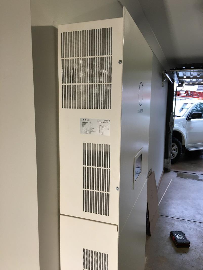
6 sonnenbatterie eco 8.0 Single Phase System Components Main Cabinet 6

7 sonnenbatterie eco 8.0 Single Phase System Components Battery Module 7
8 sonnenbatterie eco 8.0 Single Phase System Components Extension Cabinets & Pedestal 8
9 sonnenbatterie eco 8.0 Single Phase System Component Descriptions 9

10 sonnen Installation
11 Technical Data 11
12 Technical Data 12
13 Technical Data Charge Rates 13
14 Warnings When carrying our electrical work on the storage system, the following must be observed:» Switch off the storage system.» Disconnect the relevant electrical circuits.» Secure against anyone switching on the device again.» Check that the device is disconnected from the power supply.» Only authorised electricians are permitted to carry out electrical work. Touching components inside the storage system poses a danger to life due to electrocution.» Do not touch any components.» Do not remove any plastic covers.» Never reach below covers. 14
.")

15 Warnings Risk of Burns:» Very high short-circuit currents are possible and the following must be observed when working with the battery modules:» The battery module is activated when the fuse connector is plugged in. The voltage runs between the plus and minus contacts of the battery module (nominal voltage of battery modules 51.2 V DC).» The battery module is deactivated when the fuse connector is unplugged. No voltage runs between the plus and minus contacts of the battery module. If all interconnected battery modules are deactivated, it is safe to work on a battery module. When working on the DC circuit:» Set aside metal jewellery.» Switch off the storage system.» Switch off the series fuse.» Fuse connectors on all battery modules ae supplied separately do not install until commissioning system. 15

16 Location Selection Observing minimum distances.» Observe the specified minimum distances to neighbouring objects.» The minimum distances ensure that:» there is sufficient heat dissipation, the storage system door can be opened easily and» there is sufficient space for maintenance work. 16


17 Safe Handling of Equipment 17


18 Safe Handling of Equipment 18

19 OH&S + Risk Assessment & Work Site Safety 19

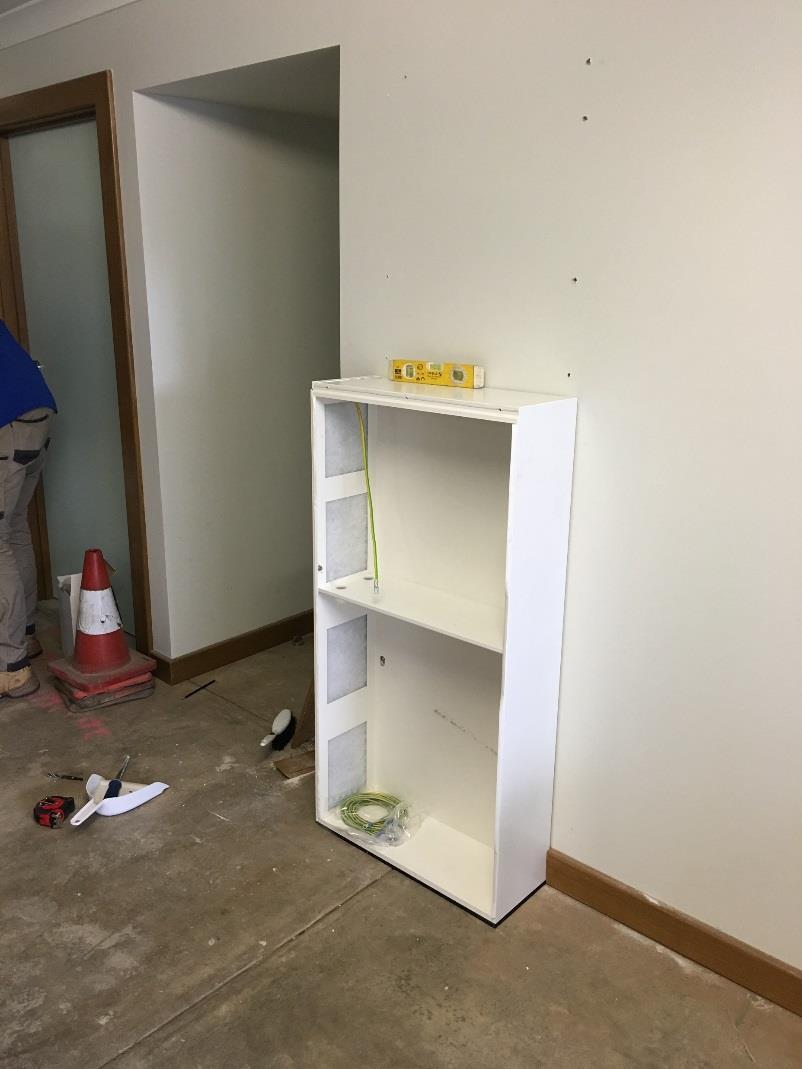
20 Location Selection Component Options.» The storage system with the optional extension cabinet must be floor mounted.» A storage system without the optional extension cabinet must be mounted to the wall with screws.» Use only screws with the following properties:» The diameter of the screw head (see figure) must be between 13 mm and 15 mm.» The screw diameter must be 8 mm.» The screw head must not exceed 5mm. 20


21 Levelling Mat or the Pedestal The levelling mat (1) is part of the scope of delivery for the extension cabinet. It is used to compensate uneven floors. Alternatively the extension cabinet can be placed on an optional pedestal (3) instead of the levelling mat. This is helpful if the extension cabinet doesn t meet flush with the wall (e.g. because a skirting board is mounted)..» Place the levelling mat or the pedestal at the preferred installation location. 21
22 Setting Out Main Cabinet Plus Small Extension Cabinet (up to 10 kwh) For storage systems consisting of main and small extension cabinet:» Drill the holes shown in red in figure on the left.» Note that the storage system must be placed on the levelling mat or the pedestal (C). 22
23 Setting Out Main Cabinet Plus Big Extension Cabinet (up to 16 kwh) For storage systems consisting of main and small extension cabinet:» Drill the holes shown in red in figure on the left.» Note that the storage system must be placed on the levelling mat or the pedestal (C). Without extension cabinet:» If the storage system is used without extension cabinet it is a good idea to observe the dimensions provided in one of the two figures. That way no new holes need to be drilled if the storage system is extended at a later time. 23

24 Setting Out 24
25 Opening the Main Cabinet Doors & Extension Housing Cover» Remove the two Allen screws on the left hand side of the main cabinet, the three screws on the extension housing.» The main cabinet door can then be opened, the extension housing cover slides up. 25
26 Removing the Filter Plates The filter plates of the main and optional extension cabinet can be removed. Removing them makes it easier to install the battery modules later.» Remove the nuts (1) inside the main and extension cabinet.» Slide the covers up (2) and take off the cover and place it to the side.. 26

27 Mounting the Extension Housing There are keyhole attachments on the rear of the main cabinet. The main cabinet is mounted using these attachments..» The screw should not be completely screwed in.» The screw head should protrude from the wall by approx. 2 mm 27
28 Mounitng the Main Cabinet Hang the main cabinet on the previously mounted screws. Remove the blind caps. The blind caps are located at the bottom of the main cabinet. 28


29 Installing Extension Cabinet 29

30 Installing Extension Cabinet 30


31 Installing Main Cabinet 31


32 Installing Main Cabinet 32
33 Mounting the Main Cabinet An earth conductor is already connected in the extension cabinet.» Connect the other end of the earth conductor to the earth bolt in the main cabinet. 33


34 Earthing Both Cabinets 34


35 Earthing Both Cabinets 35


36 Remove Access Panels & Setting Out Cabling 36


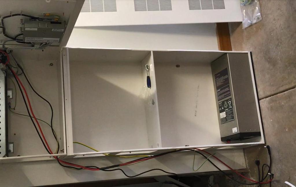
37 Electrical Connections Battery Modules Before working on the battery modules remove the battery fuse connector. Differing battery module voltages lead to high compensating currents when the storage system is switched on.» Measure the voltages between the internal plus and minus poles of all battery modules (see figure below) and note these down.» The battery modules are only allowed to be installed if the maximum deviation between the measured voltages is less than 1 V.» If the deviation is greater than 1 V notify the service team. 37


.")
38 Electrical Connections Battery Modules Numbering the Modules Apply the stickers to the modules, numbering will start at zero.» Set the communication addresses for the battery modules using the rotary switch.» The communication address needs to match the number of the battery module.» Slide the termination switch (switch 4) of the battery module with the highest number1 up (switch position ON).» Ensure that the termination switches of all other battery modules are in switch position OFF.. 38

39 Electrical Connections Battery Modules Positioning the Modules If no extension cabinet is used:» Position the battery module as shown in the left part of the image. If the extension cabinet is used:» Position the battery modules as shown in the right part of the image. If the extension cabinet is used but not completely full:» Position the battery modules from the floor up without any gaps between numbering the lowest module as 0. 39

40 Installing Batteries 40


41 Installing Batteries 41


42 Installing Batteries 42
 with a torque of 5 Nm.» Connect the other end of the earth conductors to the earth connections (14) of the battery modules.")
43 Electrical Connections Battery Modules Grounding Grounding of the battery modules:» Connect all earthing wires to the earthing pin (1).» Take care of the positioning of the components (2) to (12). The cable lugs have to be arranged circularly.» Tighten the locking nut (12) with a torque of 5 Nm.» Connect the other end of the earth conductors to the earth connections (14) of the battery modules.» Tighten the socket screws (15) with a torque of 4 Nm. 43

44 Electrical Connections Battery Modules Grounding 44

45 Electrical Connections Battery Modules DC Line Connection Incorrectly connected DC lines can cause a short circuit and thus high heat generation. Improperly connected DC lines can also create high resistance at the point of contact. As very high currents flow through the DC circuit, this high contact resistance can lead to great loss of energy (electrical energy is converted into heat).» Check all plug connections. Only red lines are allowed to be plugged into red sockets. Only black lines are allowed to be plugged into black sockets.» Ensure that all DC lines are plugged into the sockets all the way.» Ensure that all battery modules are connected in parallel, i.e. all plus poles of the battery modules are connected together (red to red). Likewise, ensure that all minus poles of the battery modules are connected together (black to black). 45


46 Electrical Connections Battery Modules DC Line Connection Connect the DC lines as shown, observe the following points.» The plus line is connected from F1 to the plus pole of battery module 0.» The minus line is connected from terminal X3 to the minus pole of the last battery module (with the highest number).» With a sonnenbatterie eco 8/2 this is battery module 0,» with a sonnenbatterie eco 8/4 this is battery module 1,» with a sonnenbatterie eco 8/6 this is battery module 2, and so on...» with a sonnenbatterie eco 8/16 this is battery module 7. 46

47 Electrical Connections Battery Modules BMS Connection Connect the BMS lines as shown in the following figures. Use the supplied BMS communication lines. 47


48 Electrical Connections Battery Modules DC Line Connection + BMS 48

49 Electrical Connections - Metering 49
 protects the connection line to the storage system.")
50 Electrical Connections Meter Board Components Approx. 25 cm of free space on a mounting rail is required for placing the components.» The miniature circuit breaker (1) protects the connection line to the storage system.» The power meter (2) and the transformer interfaces (3) are used to measure the consumption and generation of power in the building.» The miniature circuit breaker (4) protects the line that is connected to the input for measuring the voltage of the power meter (2).» The RCD (5) protects against high touch voltage in the event of a fault. 50
51 Electrical Connections Power Meter The following points must be observed when connecting the power meters:» The lines connected to the voltage measurement terminal strip (3) must be protected by the supplied miniature circuit breakers (B6). The supplied miniature circuit breakers do not have to be installed if the lines are already protected by existing circuit breakers. 1 A1 input for generation 2 2 A2 input for consumption 3 Voltage measurement terminal strip 4 Power meter 5 Transformer interface for consumption 6, 7, 8 Clamp-on current transformer for consumption L1, L2, L3 9, 10, 11 Clamp-on current transformer for generation L1, L2, L3 12 Transformer interface for generation 13 Modbus terminal strip 51
 mains, the voltage terminal strip must be wired like it is shown on the left part of the figure.")
52 Electrical Connections Power Meter The connection to the voltage terminal strip depends on the number of phases.» In the case of a single-phase (1~) mains, the voltage terminal strip must be wired like it is shown on the left part of the figure. In case of a three phase (3~) mains wire as shown on the right part of the figure.» The clamp-on current transformers are clamped across the affected lines.» The energy flow direction of the clamp-on current transformer must be observed.» The energy flow in the line must run from K to L. 52


53 Electrical Connections Power Meter PV Inverter Output In the case of a one-phase PV inverter or a singlephase mains, only the clamp-on current transformer for the phase in question is connected. The other two clamp-on current transformers must not be connected. Do not confuse the phases. Power measurement only works if the current and voltage of the same phase are measured. 53
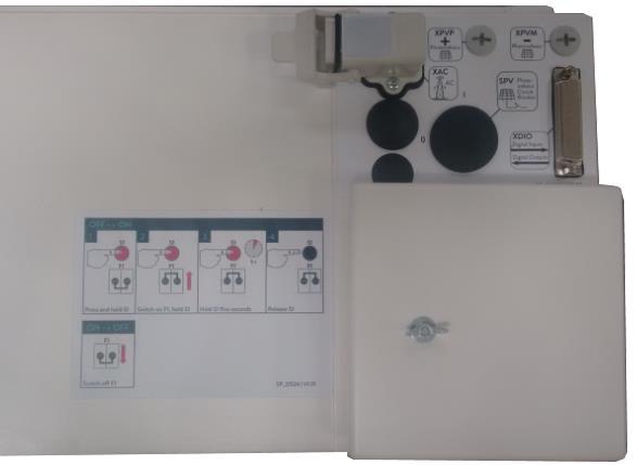

54 Electrical Connections Connection Panel 54
. Otherwise it is not possible to close the cover.» The storage system automatically establishes the connection to the internet once the Ethernet line has been correctly connected.")
55 Electrical Connections Ethernet Connection Use a patch cable with the following properties as the Ethernet line:» Category: Cat 5 e» Shielded» The patch cable has an angled connector (1). Otherwise it is not possible to close the cover.» The storage system automatically establishes the connection to the internet once the Ethernet line has been correctly connected. 55
56 Electrical Connections Modbus Line Measurement data is transmitted from the power meter to the storage system using the Modbus line:» Category: Cat 5 e» Shielded» The patch cable has an angled connector (1). Otherwise it is not possible to close the cover.» Connect the patch cable (1) as shown in the following figure. 56
57 Electrical Connections Main AC Connection The following points must be observed when carrying out electrical work on the storage system or on the electrical supply:» Switch off the storage system.» Disconnect the relevant electrical circuits.» Secure against anyone switching on the device again.» Check that the device is disconnected from the power supply.» Only authorised electricians are permitted to carry out electrical work.. 57

58 Installation Commissioning 58

59 Installation Commissioning Checks 59

60 Installation Commissioning Labelling Guide 60


61 Installation Commissioning Labelling Guide 61

62 Installation Commissioning AS/NZS Labelling Requirements 62

63 sonnen Apps, Monitoring & Energy Control
64 Installation Commissioning Establishing Connection Connect the laptop (2) to the router of the home network. The storage system must also be connected to the router of the home network. 64

65 Installation Commissioning Establishing Connection Start a browser (e.g. Firefox, Chrome, Safari, ) on your laptop or pc.» Enter the address findemeine.sonnenbatterie.de in the address line of your browser.» Click the button Anzeigen.» The login page appears. 65
66 Installation Commissioning Wizard Running the commissioning wizard.» Select your preferred language from the language selection list (1).» Select the User Installer from the user selection list (2).» Enter in the password entry box (3).» Click the button (4) to confirm your entries. After that the commissioning wizard will start.» Run the commissioning wizard until it is fully completed. 66
67 Sonnen System Monitoring Basic overview of installation 1. Grid electrical mains 2. Measurement of generation 3. PV system 4. Storage system 5. Measurement of consumption 6. Loads in the building (e.g. washing machine, cook top, lights, refrigerator, etc.) 67
68 Sonnen System Monitoring End User Online Monitoirng Login Procedure Logging into the internet portal.» To log into the internet portal, enter the following web address into the browser:» The login window shown opens:» Enter your access data, which was provided as part of the scope of delivery.» Click on the Log in button. 68


69 Sonnen System Monitoring End User Online Monitoirng Login Procedure 69

70 Sonnen System Monitoring End User Online Monitoirng Login Procedure 70

71 Sonnen System Monitoring End User Online Monitoirng Overview Page The overview page shows a summary of all of the information which can be seen on the portal.» You can click on the Status, Control, Graph and Forecast buttons in order to open the specific page. 71
72 Sonnen System Monitoring End User Online Monitoirng Status Page The status page (shown in the figure on the right) shows the following current measured values:» Current generation» Current consumption» Current usage/current feed-in» Current charging status. 72
. 4. Time is on the x-axis. 5. Energy legend. 6. Navigate to previous or later timeframes. 7. Printing shown graph. 8. Select a date. 9.")
73 Sonnen System Monitoring End User Online Monitoirng Graph Page The power graph presents the different energy flows in relation to time: 1. Day, week, month or year 2. Activates / deactivate full-screen mode. 3. Power in watts (kw). 4. Time is on the x-axis. 5. Energy legend. 6. Navigate to previous or later timeframes. 7. Printing shown graph. 8. Select a date. 9. Cursor over the graph shows the exact values of the energy. 73


74 Sonnen System Monitoring End User Online Monitoirng Pie Charts Two pie charts are shown below the power graph. The pie charts always refer to the timeframe shown in the power graph.» Production» Consumption 74

75 Sonnen System Monitoring End User Online Monitoirng Pie Charts 75
76 Sonnen System Predictive Control End User Online Monitoirng Forecasting Page The storage system is able to forecast consumption in the near future (blue) based on previous consumption trends. Accessing weather data can also produce a generation forecast (yellow). 76

77 Sonnen Apps, Monitoring & Energy Control Smart Phone App The intuitive sonnenapp communicates with the sonnenbatterie and informs the user with a button-click about all current values. The sonnenapp shows clearly how much energy the user has produced, consumed or has stored in the sonnenbatterie. With the sonnenapp the user can directly control individual electrical appliances via intelligent radio sockets, the sonnensmart-plugs, will receive detailed data on the consumption of certain devices, as they measure the actual power of the device. The sockets are controlled either manually or automatically. This means: When surplus power production of the PV system on particularly sunny days, the coupled devices will be providing automatically with power. For example, you can start your washing machine comfortably on your way. So you increase effectively your own consumption and still consume even more electricity 77

78 Sonnen Apps, Monitoring & Energy Control Smart Phone App 78


79 Sonnen Apps, Monitoring & Energy Control Smart Phone App Z-Wave is a wireless technology that lets smart devices talk to one another. Household products, like lights, door locks and thermostats are made smart when Z-Wave connectivity is added inside the product s design.» Over 325 manufacturers, including some of the biggest names in consumer electronics and smart home, it is easier to say what Z- Wave does not work wit» Z-Wave has another level of security which uses AES128 encryption.» Z-Wave is a highly 'scalable' technology - meaning it can control anywhere from one device all the way up to 232 devices with just one network. 79

80 Sonnen Apps, Monitoring & Energy Control Smart Phone App 80

81 Installation Complete 81


82
Installation instructions. sonnenbatterie.de. for authorised electricians. KD-431 Part no.
 Installation instructions for authorised electricians sonnenbatterie eco 8. KD- Part no. Version X0 info@sonnenbatterie.de sonnenbatterie.de EN IMPORTANT Read this documentation carefully before installation.
User Monitoring Smartphone App
 User Monitoring Smartphone App Sonnen User Portal Sonnen User Portal Registration From any internet browser the end user will need to type https://meine.sonnenbatterie.de/login into the search engine search
SPECIAL INSTRUCTIONS FOR CAPACITORS COMPACT GENERATORS
 SPECIAL INSTRUCTIONS FOR CAPACITORS COMPACT GENERATORS (WITH CAPACITOR CHARGER BOARD A3517-02) The process depends on Generator and System configuration. This document applies to installation of Capacitors
Huawei Solar Product Training HUAWEI TECHNOLOGIES CO., LTD.
 Huawei Solar Product Training HUAWEI TECHNOLOGIES CO., LTD. Contents Overview of the Product Range Huawei Solar Inverter Technical Information Huawei Smartlogger Technical Information NetECO Portal Brief
BLUE 3 INSTALLATION GUIDE
 BLUE 3 INSTALLATION GUIDE CATCH Power BLUE 3 Installation manual - Page 1 IMPORTANT This product must be installed by a licensed electrician. This product must be installed according to the AS3000 Australian
TS001 Sonnen eco 8 Trouble Shooting Guide. Issue Reason Solution
 TS001 Sonnen eco 8 Trouble Shooting Guide This guide covers both the eco 8.2 single phase series products as well as the eco 8.03 three phase series, differences between each will highlighted within the
IF-80x Outdoor Terminal
 95-10330_IF-800 V2016-10-20 Outdoor Terminal IF-80x Outdoor Terminal 1 IF-800 Outdoor / IF-801 We are pleased that you have decided to use a terminal of the IF-80x series for recording access data. Scope
Comissioning Assistant - Update. Version
 Comissioning Assistant - Update Version 0.8.10.9478 Within the local network (i.e. with a laptop connected to the clients router) the installer will need to type https://finde-meine.sonnenbatterie.de/
InnoMedia Business VoIP ATA Models
 InnoMedia Business VoIP ATA Models MTA8328-4, MTA8328-8, MTA8328-24 Quick Installation Guide Important Safety Instructions Protective Earthing Protective earthing is used as a safeguard. This equipment
Please read these instructions carefully before installing This will ensure an easy start and a great first customer experience with TS4 installation
 Please read these instructions carefully before installing This will ensure an easy start and a great first customer experience with TS4 installation INTERACTIVE INSTALLATION AND SAFETY MANUAL FOR TS4:
Three Phase Residential Solution for Australia, System Design and Installation Guidelines
 Three Phase Residential Solution for Australia, System Design and Installation Guidelines This document describes how to design and install SolarEdge three phase inverters for residential installations.
one cool inverter. GT Series Solar Inverter Quick Install Guide v1.4
 one cool inverter. GT Series Solar Inverter Quick Install Guide v1.4 This quick installation guide must be used in conjunction with the Installation Manual. For installation support contact your local
icore Kiosk system Installation Guide
 icore Kiosk system Installation Guide The reproduction, transmission or use of this document or its contents is not permitted without express authority. Offenders will be liable for damages. All rights,
Product and functional description. Application Program. instabus EIB Technical product information. April (6 x AC 230 V / 0,05 A)
") Product and functional description also functions if the bus cable is not connected or if the bus communication fails. After a long push button action (> 2 s), the other valve group is selected. The yellow
Product and functional description also functions if the bus cable is not connected or if the bus communication fails. After a long push button action (> 2 s), the other valve group is selected. The yellow
Bulletin Installation of solar photovoltaic systems Rules , , , , and
 Bulletin 64-5-0 Installation of solar photovoltaic systems Rules 64-060, 64-200, 64-214, 84-020, 84-024 and 84-030 Scope (1) Introduction (2) Disconnecting means (a) Disconnecting means for solar photovoltaic
User Manual. Solar Inverter for Water Pump
 User Manual Solar Inverter for Water Pump SP Revival Series Version: 1.2 Table Of Contents ABOUT THIS MANUAL... 1 Purpose... 1 Scope... 1 SAFETY INSTRUCTIONS... 1 Inspection... 1 Installation... 1 Operation...
ILUMEN PID SOLUTION INDOOR OUTDOOR ILUMEN PIDBOX MINI INSTALLATION MANUAL. Ilumen PIDbox mini Version 1.5
 ILUMEN PID SOLUTION ILUMEN PIDBOX MINI INSTALLATION MANUAL INDOOR OUTDOOR Ilumen PIDbox mini Version 1.5 1 TABLE OF CONTENT 1 Information on this manual... 3 1.1 Validity... 3 1.2 Target group... 3 1.3
PV Inverter SUNNY BOY 4000TL / 5000TL
 PV Inverter SUNNY BOY 4000TL / 5000TL Installation Guide SB40TL_50TL-IEN081211 IME-TB-SBXTL-20 Version 1.1 EN Power curve of the past 16 hours or past 16 days (switching the display is done by knocking
PIX 515/515E. PIX 515/515E Product Overview CHAPTER
 CHAPTER 4 PIX 515/515E This chapter describes how to install the PIX 515/515E, and includes the following sections: PIX 515/515E Product Overview Installing a PIX 515/515E PIX 515/515E Feature Licenses
2M Outdoor Motorized Bullet Camera
 2M Outdoor Motorized Bullet Camera 8608586000010 Quick Installation Guide Please follow the installation steps below to set up your 2MP Bullet IP Camera. Check the package contents against the list below.
SINAMICS. SINAMICS G120P dv/dt filter plus Voltage Peak Limiter. Safety information 1. General. Mechanical installation. Electrical installation 4
 Safety information 1 General 2 SINAMICS SINAMICS G120P dv/dt filter plus Voltage Peak Limiter Operating Instructions Mechanical installation 3 Electrical installation 4 Maintenance and servicing 5 Technical
Accessories for stand-alone gird inverter SMART LOAD 6000
 Accessories for stand-alone gird inverter SMART LOAD 6000 Technical Description SL6000-TEN081820 98-2001320 Version 2.0 EN Table of Contents Table of Contents 1 Notes on this Manual..............................
dv/dt filter compact plus Voltage Peak Limiter SINAMICS SINAMICS G120P dv/dt filter compact plus Voltage Peak Limiter Safety information 1 General 2
 dv/dt filter compact plus Voltage Peak Limiter SINAMICS SINAMICS G120P dv/dt filter compact plus Voltage Peak Limiter Operating Instructions Safety information 1 General 2 Mechanical installation 3 Electrical
Obtaining Documentation and Submitting a Service Request, page xvii Safety Warnings, page xvii Safety Guidelines, page xx
 Preface Obtaining Documentation and Submitting a Service Request, page xvii Safety s, page xvii Safety Guidelines, page xx Obtaining Documentation and Submitting a Service Request For information on obtaining
SINAMICS G130. Terminal Module 150 (TM150) Operating Instructions 03/2013 SINAMICS
 Operating Instructions 03/2013 SINAMICS") SINAMICS G130 Operating Instructions 03/2013 SINAMICS s Safety information 1 General information 2 SINAMICS SINAMICS G130 Mechanical installation 3 Electrical installation 4 Technical specifications 5
SINAMICS G130 Operating Instructions 03/2013 SINAMICS s Safety information 1 General information 2 SINAMICS SINAMICS G130 Mechanical installation 3 Electrical installation 4 Technical specifications 5
Digital I/O Module. Impro (DIO) Digital I/O Module INSTALLATION MANUAL
 Digital I/O Module INSTALLATION MANUAL") COMPONENT CODES: HMI700-1-0-NN-XX HMI701-1-0-NN-XX Digital I/O Module Impro (DIO) Digital I/O Module Specifications INSTALLATION MANUAL The DIO is a Cluster Expansion Module that works in conjunction with
COMPONENT CODES: HMI700-1-0-NN-XX HMI701-1-0-NN-XX Digital I/O Module Impro (DIO) Digital I/O Module Specifications INSTALLATION MANUAL The DIO is a Cluster Expansion Module that works in conjunction with
Device for Plant Monitoring SUNNY WEBBOX with Bluetooth Wireless Technology
 Device for Plant Monitoring SUNNY WEBBOX with Bluetooth Wireless Technology Installation Manual SWebBox20-IA-en-12 Version 1.2 EN Table of Contents Table of Contents 1 Information on this Manual.........................
M215 (M215-60) Safety
 Safety") M215 QUICK INSTALL GUIDE M215 (M215-60) Safety Important Safety Information This document contains important instructions to use during installation and maintenance of the Enphase M215 Microinverter. To
M215 QUICK INSTALL GUIDE M215 (M215-60) Safety Important Safety Information This document contains important instructions to use during installation and maintenance of the Enphase M215 Microinverter. To
GRID-TIED SOLAR INVERTER 1.5KW ~ 6.0KW V.1.2
 USER MANUAL MPI-1500/2000/3000/4000/6000 Series GRID-TIED SOLAR INVERTER 1.5KW ~ 6.0KW V.1.2 WWW.MPPSOLAR.COM WARNING: ONLY A CERTIFIED ELECTRICIAN OR TRAINED ASSEMBLING PROFESSIONAL SHOULD OPEN OR INSTALL
Replacing the Power Supply
 APPENDIX B This appendix includes information on how to replace the power supply for the Cisco AS550XM universal gateway and contains the following sections: Safety Recommendations, page B-1 Required Tools
Quick Start. This document describes how to install the Juniper Networks PTX5000 Packet Transport
 PTX5000 Packet Transport Router Quick Start September 2017 Part Number: 530-066788 Revision 01 This document describes how to install the Juniper Networks PTX5000 Packet Transport Router. Contents Quick
SUNCLIX Connection technology for photovoltaics
 SUNCLIX Connection technology for photovoltaics Connection technology for photovoltaics Are you looking for innovative and reliable connection technology for your PV modules, inverters or the complete
FIBARO SINGLE SWITCH
 OPERATING MANUAL EN FIBARO SINGLE SWITCH FGBHS-213 CONTENTS #1: Description and features 3 #2: Supported loads 4 #3: Installation 5 #4: Pairing the accessory 7 #5: Reset 8 v1.1 #6: Functionality 9 #7:
Technical Data. Wi-Fi Socket Range Extender. Features: 922WR
 Technical Data Wi-Fi Socket Range Extender Brief product description: Eliminate dead spots and expand your Wi-Fi coverage with the Wi-Fi Socket Range Extender. Features: Improved Wi-Fi coverage throughout
HT2000 Transverter Installation & Operation Manual
 HT2000 Transverter Installation & Operation Manual 1 A message from the team at Heart Transverter S.A. Thanks for your recent purchase of the HT2000 Power inverter in combination with the HTREM Remote
Junos WebApp Secure 5.0 Hardware Guide
 Junos WebApp Secure 5.0 Hardware Guide Junos WebApp Secure 5.0 Hardware Guide This document contains a specification for the MWS1000 hardware appliance, as well as instructions for installation into a
Firmware Update with SD Card SUNNY BOY WINDY BOY SUNNY TRIPOWER
 Firmware Update with SD Card SUNNY BOY WINDY BOY SUNNY TRIPOWER Technical Description NG_UpdSD-TB-TEN114530 Version 3.0 EN SMA Solar Technology AG Table of Contents Table of Contents 1 Information on
User s Manual of Web monitor HMI-901
 User s Manual of Web monitor HMI-901 Afore New Energy Technology (Shanghai) Co., Ltd. 1. Wiring 1.1 Definition of different wire (picture 1-1): Colour Red Black Yellow White Definition +5V GND 485A 485B
SUN KTL-M0 Quick Guide (Europe Edition) Issue: 01 Part Number: Date: HUAWEI TECHNOLOGIES CO., LTD.
 Issue: 01 Part Number: Date: HUAWEI TECHNOLOGIES CO., LTD.") SUN2000-60KTL-M0 Quick Guide (Europe Edition) Issue: 01 Part Number: 91509499 Date: 2018-02-10 HUAWEI TECHNOLOGIES CO., LTD. NOTICE The information in this document is subject to change without notice.
SUN2000-60KTL-M0 Quick Guide (Europe Edition) Issue: 01 Part Number: 91509499 Date: 2018-02-10 HUAWEI TECHNOLOGIES CO., LTD. NOTICE The information in this document is subject to change without notice.
A Axis M-Functions Level 1 A Axis Standard A Axis SMT Level 2. Each console includes the following:
 Hardware List The 3000M Crusader II Upgrade system has been custom configured to provide the necessary hardware required for installation on your machine. Verify that you have received all the correct
BS 287 DUAL CHANNEL POWER SUPPLY. User Manual. January 2017 V1.0
 BS 287 DUAL CHANNEL POWER SUPPLY User Manual January 2017 V1.0 Table of contents 1.0 SAFETY INSTRUCTIONS... 3 2.0 GENERAL DESCRIPTION PS 289... 4 3.0 MECHANICAL INSTALLATION... 5 4.0 MAINS POWER & SAFETY
XDBKITS5 Bus / DB Terminal Kit (Size 5) Installation Manual DPD00116
 Installation Manual DPD00116") XDBKITS5 Bus / DB Terminal Kit (Size 5) Installation Manual DPD00116 XDBKITS5 Option Kit Installation Manual vacon 3 Installing the Bus / DB Terminal Option Kit Introduction The XDBKITS5 option kit is
XDBKITS5 Bus / DB Terminal Kit (Size 5) Installation Manual DPD00116 XDBKITS5 Option Kit Installation Manual vacon 3 Installing the Bus / DB Terminal Option Kit Introduction The XDBKITS5 option kit is
3RV1 Circuit-Breakers
 SIRIUS 3R Description Mountable accessories 3RV1 Circuit- Breakers Circuit-breaker S00 with mountable accessories 3 2 1 5.1 NSK-7715a 4 Circuit-breaker S0 with mountable accessories 1 7 3 5.2 2 6 NSK-7716a
dynamic white par manual
 dynamic white par manual V2.0 AUGUST 2017 table of CONTENTS Dimensions 1 Safety information 2 Fixture overview 4 Introduction 5 AC power 5 Power voltage 5 Power cables 6 Relaying power to other devices
Installing the Cisco AS5400XM Universal Gateway
 CHAPTER 3 Installing the Cisco AS5400XM Universal Gateway This chapter guides you through the installation of the Cisco AS5400XM universal gateway and includes the following sections: Setting Up the Chassis,
Electrical Integration of PV Systems. Ridha Hamidi, Ph.D.
 Electrical Integration of PV Systems Ridha Hamidi, Ph.D. 1 Many articles in the NEC are applicable to the electrical integration of a PV system, particularly Article 690. 2 The NEC defines the various
User Manual V1.0. User Manual of Z10 Internal Data Collector
 User Manual V1.0 User Manual of Z10 Internal Data Collector Catalogue 1. Unpacking... 2 2. PV Data Collector... 2 3. S/N Label... 3 4. Wi-Fi Installation... 3 5. Wi-Fi Card Information... 7 6. Register
Line reactors SINAMICS. SINAMICS G130 Line reactors. Safety information 1. General. Mechanical installation 3. Electrical installation
 Safety information 1 General 2 SINAMICS SINAMICS G130 Mechanical installation 3 Electrical installation 4 Technical specifications 5 Operating Instructions Control version V4.7 04/2014 A5E00331462A Legal
Front-door station series for surface-mounting Profi-Economic PES Profi-Design PDS
 Product information Front-door station series for surface-mounting Profi-Economic PES Profi-Design PDS PI_GB_PES_PDS_Art0015689_1v0.doc 2 10/2005 In Table of contents Scope of delivery...3 Safety notices...3
Please read these instructions carefully before installing This will ensure an easy start and a great first customer experience with TS4 installation
 Please read these instructions carefully before installing This will ensure an easy start and a great first customer experience with TS4 installation INTERACTIVE INSTALLATION AND SAFETY MANUAL FOR TS4:
Site Preparation CHAPTER
 CHAPTER 3 Site Preparation This chapter describes the steps to take and the considerations you should keep in mind prior to installing the modules in an open rack. It also contains information that applies
S-14 S-14. Compact Digital Multimeter. Compact Digital Multimeter
 S-14 Compact Digital Multimeter S-14 Compact Digital Multimeter SAFETY INFORMATION The following safety information must be observed to insure maximum personal safety during the operation at this meter
4.7 Digital Input/Output Module 07 DC digital inputs, 8 digital outputs, 8 configurable inputs/outputs, 24 V DC, CS31 system bus
 4.7 Digital Input/Output Module 16 digital inputs, 8 digital outputs, 8 configurable inputs/outputs, 4 V DC, CS31 system bus 1 3 Advant Controller 31 I/O Unit ERR Test 4 1 Fig. 4.7-1: Digital input/output
PHOENIX CONTACT Pin. SUBCON-PLUS M ARCNET, MULTI/MININET (B&R), SYSTEM 2003 (B&R), P-NET SUCONET K1, K2 (EATON/Moeller),
, SYSTEM 2003 (B&R), P-NET SUCONET K1, K2 (EATON/Moeller),") Fast connector with screw terminal block connection for fieldbus systems Data sheet 00287_en_02 PHOENIX CONTACT 207-04-2 Description The SUBCON-PLUS/... D-SUB series is specifically designed for use in
Fast connector with screw terminal block connection for fieldbus systems Data sheet 00287_en_02 PHOENIX CONTACT 207-04-2 Description The SUBCON-PLUS/... D-SUB series is specifically designed for use in
When any of the following symbols appear, read the associated information carefully. Symbol Meaning Description
 Uni-I/O Modules Installation Guide UID-0808R, UID-0808T, UID-1600,UID-0016R, UID-0016T Uni-I/O is a family of Input/Output modules that are compatible with the UniStream control platform. This guide provides
Operating Manual MULTICLUSTER BOX 12
 Operating Manual MULTICLUSTER BOX 12 MC-BOX-12-3-20-BE-en-10 Version 1.0 ENGLISH Legal Provisions Legal Provisions The information contained in this document is the property of. Publishing its content,
INSTALLATION INSTRUCTIONS FOR
 INSTALLATION INSTRUCTIONS FOR MODEL 3314 LED www.sportablescoreboards.com 1 Table of Contents DESCRIPTION... 3 THE SCOREBOARD SYSTEM SHOULD INCLUDE THE FOLLOWING PARTS:... 3 INSTRUCTIONS FOR REPORTING
Cat. No. S012-EN-01. Ilumen PIDbox INSTALLATION MANUAL
 Cat. No. S012-EN-01 ZX-T PV-PID-BOX-_ Series _A Ilumen PIDbox INSTALLATION MANUAL Installation Manual Ilumen PIDbox v2.4 1 Information on this manual... 3 1.1 Validity...3 1.2 Target group...3 1.3 Additional
MODEL: GR8-EM. Communication Adaptor GR8 Series
 Communication Adaptor GR8 Series Ethernet/RS-485 Adaptor (Modbus use) Functions & Features Bidirectional protocol converter for Modbus/TCP (Ethernet) and Modbus RTU (RS-485) Fast response time thanks to
SOLARIMMERSION IV Advanced Installation Manual v1.9
 SOLARIMMERSION IV Advanced Installation Manual v1.9 1 Contents 1. Overview 2. Technical Specifications 3. Installation Mounting Electrical Installation Clamp Installation Wiring Diagrams 4. Installation
JUMO TYA 201 Single-Phase SCR Power Controller For controlling resistive/inductive loads
 Data sheet 709061 Page 1/21 JUMO TYA 201 Single-Phase SCR Power Controller For controlling resistive/inductive loads The JUMO TYA 201 represents a consistent further development of the JUMO power controller
Installing the Cisco MDS 9020 Fabric Switch
 CHAPTER 2 This chapter describes how to install the Cisco MDS 9020 Fabric Switch and its components, and it includes the following information: Pre-Installation, page 2-2 Installing the Switch in a Cabinet
B-Box H Installation Guidance
 B-Box H Installation Guidance 27th_Sep.2017 1 / 22 Contents SAFETY... 3 1 PRODUCT OVERVIEW... 4 2 BCU INTRODUCTION... 6 3 DESCRIPTION OF B-PLUS-H INTERFACE AND TERMINAL... 8 4 B-BOX HV INVERTER CONFIGURATION
SmartLogger1000 Quick Guide. Issue: 10 Part Number: Date: HUAWEI TECHNOLOGIES CO., LTD.
 SmartLogger1000 Quick Guide Issue: 10 Part Number: 31505707 Date: 2017-06-13 HUAWEI TECHNOLOGIES CO., LTD. 1. The information in this document is subject to change without notice. Every effort has been
OPERATING INSTRUCTION
 OPERATING INSTRUCTION AUTORANGING MULTIMETER MAX Ω F C 10A MAX every 15 min. COM V SAFETY INFORMATION The following safety information must be observed to insure maximum personal safety during the operation
SEM3 - Embedded Micro Metering Module
 SEM - Embedded Micro Metering Module Quick Reference Guide and Installation Instructions Scan QR Code for more information usa.siemens.com/sem Installation! DANGER Hazardous Voltage. Will cause death or
USER MANUAL VIBRATION CONTROL RMA-POWER-BOX 107/230
 USER MANUAL VIBRATION CONTROL Version 2.2 1 IMPORTANT NOTES Electrical danger within the meaning of this documentation or the warning labels on the product itself respectively means that death, serious
5KW Parallel Installation Guide
 5KW Parallel Installation uide 1. Introduction This inverter can be used in parallel with maximum 6 units. The supported maximum output power is 60KW/60KVA. 2. Parallel cable You will find the following
Remote RMM-1400 Intelligent Remote Site Management Device. Installation Guide
 Remote RMM-1400 Intelligent Remote Site Management Device Guide INSTALLATION GUIDE Westell Technologies Part # 030-300645 Rev. A Copyright 2015 by Westell Technologies. All Rights Reserved. Westell, Kentrox
How to choose the correct Mount Kelvin central unit
 Installation guide Outside world Property Wirepas mesh Mount Kelvin app Internet connection Ethernet DALI 3rd party integrations Mount Kelvin cloud Mount Kelvin central unit Voice control EnOcean wireless
Xcel Energy Telemetry Requirements for Distributed Energy Resource Interconnections: Revision 3.1
 Xcel Energy Telemetry Requirements for Distributed Energy Resource Interconnections: Revision 3.1 Version 3.1: September 22, 2017. Please note that this Revision 3.1 may be subject to subsequent revisions.
When any of the following symbols appear, read the associated information carefully. Symbol Meaning Description
 Uni-I/O Wide Modules Installation Guide UID-W1616R, UID-W1616T Uni-I/O Wide is a family of Input/Output modules that are compatible with the UniStream control platform. Wide Modules are 1.5 times as wide
WBS HARDWIRED SERIES 4-60KVA MAINTENANCE BYPASS SWITCH
 WBS HARDWIRED SERIES 4-60KVA MAINTENANCE BYPASS SWITCH Man 440 Issue 7 1 1. INTRODUCTION... 3 2. INSTALLATION... 3 2.1 Connection of the Mains Supply... 3 2.2 Connection of the Input to the UPS... 4 2.3
3M ID 3000 System. ID 3128 block. Disconnection module. ID 3100 block Wire guide housing
 3M ID 3000 System ID 3128 block Disconnection module ID 3100 block Wire guide housing 71 Disconnection element 72 The ID 3000 connection system is the latest generation of insulation displacement connector
CONSOLE CONNECTOR KIT 9501 INSTALLATION INSTRUCTIONS
 CONSOLE CONNECTOR KIT 9501 INSTALLATION INSTRUCTIONS FOR USE WITH: HAMMOND Organ Models L-100, M-100 Series, M-l, M-2, M-3 LESLIE Speaker Models 760, 770, 825 KIT CONTENT Console Connector Assembly 043075
NetCommWireless. Quick Start Guide NTC-30 Series - Outdoor WiFi Router
 NetCommWireless Quick Start Guide NTC-30 Series - Outdoor WiFi Router NetCommWireless Let s get this show on the road You must be excited to get started with your Outdoor WiFi Router. If all goes to plan,
4.8 Digital Input/Output Module 07 DC 92 Contents Intended purpose Displays and operating elements on the front panel Electrical connection
 4.8 Digital Input/Output Module 07 DC 9 3 configurable digital inputs/outputs, 4 V DC, electrically isolated in groups, outputs can be loaded with 500 ma, CS31 system bus 1 3 4 1 Fig. 4.8-1: Digital input/output
User's Guide. MiniTec TM Series Model MN25 MultiMeter
 User's Guide MiniTec TM Series Model MN25 MultiMeter Warranty EXTECH INSTRUMENTS CORPORATION warrants this instrument to be free of defects in parts and workmanship for one year from date of shipment (a
BS 181 SINGLE CHANNEL POWER SUPPLY USER MANUAL
 BS 181 SINGLE CHANNEL POWER SUPPLY USER MANUAL August 2016 This product is designed and manufactured by: ASL Intercom B.V. Zonnebaan 42 3542 EG Utrecht The Netherlands Phone: +31 (0)30 2411901 Fax: +31
Wise HP33 THREE PHASE HIGH PRECISION AVR SURVO-MOTOR AUTOMATIC VOLTAGE STABILIZER
 Wise HP33 THREE PHASE HIGH PRECISION AVR SURVO-MOTOR AUTOMATIC VOLTAGE STABILIZER LEN.MAN.STA.111 Rev.4.00/2010 CONTENTS 1. SAFETY INSTRUCTIONS 1 2. INTRODUCTION 2 3. FRONT PANEL AND CONNECTION BOARD 3
APS4 Inductive Proximity Sensors
 APS4 Inductive APS4-S-E-D APS4-S-E2-D APS4-M-E-D APS4-M-E2-D Compact x27 mm plastic DC 4 models available Compact polycarbonate housing; comes with mounting plate High-frequency oscillation type DC 3-wire,
Quick Start Guide V5.1.
 Quick Start Guide V5.1 1 Quick Start Guide Table of Content 1. Package Contents...1 2. Cautions... 1 3. System Requirements... 1 4. Hardware Overview... 2 4.1 Mini Dome Network Camera...2 4.2 IR Mini
Operating and mounting instructions
 General Usage IPAS DALI Gateways bring together the crossfunctional KNX installation bus and the lighting control specific DALI-Bus (IEC 60929). Lights with cost-effective, digital DALI ECGs can therefore
Safegard V4 Panel. Installation Datasheet. Safegard V4 Panel Installation Instructions and Datasheet release 1.7 August 2016
 Safegard V4 Panel Installation Datasheet ELECTROSTATIC SENSITIVE DEVICE This product forms part of a life safety system. Failure to correctly store, handle, install and maintain the product will directly
Parts List: Part # Tools List: Instructions:
 Parts List: Part # 1 pair of Dayton Audio B652s 300-652 1 Dayton Audio DTA-2 amplifier 300-385 1 MP3 module 320-350 1 7805 +5 VDC voltage regulator 7805 1 12 VDC 2A power supply 129-077 1 2.1 mm panel
Product Brochure. Series 70 erpp-fs. Web-Enabled Remote Power Panel
 Product Brochure Series 70 erpp-fs Web-Enabled Remote Power Panel erpps Remote Power Panel Purpose Increase Reliability and Safety In Two Ways With erpp Remote Power Panels Reliability Increase #1: Finger
Switches 6/1. 6/4 Introduction. 6/5 5TE8 control switches. 6/7 5TE4 8 pushbuttons. 6/9 5TE8 On/Off switches. 6/11 5TE1 switch disconnectors
 6/4 Introduction 6/5 5TE8 control switches 6/7 5TE4 8 pushbuttons 6/9 5TE8 On/Off switches 4 6/11 5TE1 switch disconnectors 6 6/1 Switch to manual? Wherever electrical systems need to be switched on or
Instruction Manual. 2in1 LAN Tester & Multimeter. Model: 57314
 Instruction Manual 2in1 LAN Tester & Multimeter Model: 57314 1 Contents Introduction... Features... Safety Precautions.. Meter Description... Electrical Specification... Operation.. AutoRanging Multimeter.
Outdoor Motorized Dome. Quick Installation Guide 86085A
 Outdoor Motorized Dome Quick Installation Guide 86085A3340020 Outdoor Motorized Dome Quick Installation Guide Please follow the installation steps below to set up Outdoor Motorized Dome IP Camera. Check
Note: All of PXC data is available on the PX3 support page. Simply visit Support page > Choose a Product > select "PX3." QS Rule.
 QUICK SETUP GUIDE Raritan PXC Thank you for purchasing the PXC intelligent power distribution unit (PDU). The intended use of PXC is distribution of power to information technology equipment such as computers
The power behind competitiveness. Delta Infrasuite Power Management. Power Distribution Unit. User Manual.
 The power behind competitiveness Delta Infrasuite Power Management Power Distribution Unit User Manual www.deltapowersolutions.com Save This Manual This manual contains important instructions and warnings
Bulletin Installation of Solar Photovoltaic Systems Section 50; Rules: , , ; Tables 11 and 19 Issued July 2010
 Ontario Electrical Safety Code - Bulletins 50-1-0 Bulletin 50-1-0 Installation of Solar Photovoltaic Systems Section 50; Rules: 84-020, 84-024, 84-030; Tables 11 and 19 Issued July 2010 Scope (1) Introduction
Selectronic accessories to support the SelectSun 3 phase grid-tie inverter range
 Selectronic accessories to support the SelectSun 3 phase grid-tie inverter range Our all new SelectSun range of 3 phase solar inverters are equally at home with or without batteries. Available in 20kW
PM Series Power Meter
 PM Series Power Meter Quick Setup Guide - PMC-1000, PMC- 1001, PMM-1000, PMB-1960 Safety Information DANGER! HAZARD OF ELECTRIC SHOCK, EXPLOSION, OR ARC FLASH Follow safe electrical work practices. See
TECHKNOW, INC. Kiosk Order Confirmation System INSTALLATION MANUAL. Revision Date: July 11, 2012 Part # Version 3.2
 document Page 1 of 18 TECHKNOW, INC Kiosk Order Confirmation System INSTALLATION MANUAL Revision Date: July 11, 2012 Part # Version 3.2 Techknow, Inc. 393 Mayfield Road Duncan, SC 29334 www.gotechknow.com
Operating and Installation Manual. EASYLAB Expansion modules Type EM-TRF for 230 V AC mains voltage
 Operating and Installation Manual EASYLAB Expansion modules Type EM-TRF for 230 V AC mains voltage Type EM-TRF-USV for 230 V AC mains voltage; provides uninterruptible power supply (UPS) The art of handling
QUICK SETUP GUIDE PMC-1000, PMC-1001, PMM-1000, PMB PM Series Power Meter. Safety Information. Equipment Maintenance and Service.
 PM Series Power Meter QUICK SETUP GUIDE PMC-1000, PMC-1001, PMM-1000, PMB-1960 Safety Information DANGER! HAZARD OF ELECTRIC SHOCK, EXPLOSION, OR ARC FLASH Follow safe electrical work practices. See NFPA
When any of the following symbols appear, read the associated information carefully. Symbol Meaning Description
 Uni-I/O Modules Installation Guide UID-0808THS Uni-I/O is a family of Input/Output modules that are compatible with the UniStream control platform. This guide provides basic installation information for
Installing the Enphase IQ Commercial Envoy
 QUICK INSTALL GUIDE (Model ENV-IQ-AM3-3P) Installing the Enphase IQ Commercial Envoy To install the Enphase IQ Commercial Envoy, read and follow all warnings and instructions in this Guide and in the Enphase
BLUE LOG XM / XC. Quick Start Guide. Version
 BLUE LOG XM / XC Quick Start Guide Version 20180827 1 DEVICE OVERVIEW (1) LED: Power supply status (2) LED: Device status (3) LED: Online status (4) USB port (5) Directional pad (6) OK button (7) ESC button