DMX-512 LED Controller w/ LED Display.
|
|
|
- Donald Newman
- 6 years ago
- Views:
Transcription
1 Food Living Outside Play Technology Workshop DMX-512 LED Controller w/ LED Display by ChromationSystems on October 28, 2011 Table of Contents DMX-512 LED Controller w/ LED Display 1 Intro: DMX-512 LED Controller w/ LED Display 2 File Downloads 2 Step 1: 3 Step 2: Sockets and Resistors 4 Step 3: Transistors, Capacitors, and Optional Vreg 5 Step 4: LED Display and Buttons, Wiring 7 Step 5: Optional Headers 9 Step 6: DMX Connector Assembly 10 Step 7: Plug It All In & Test 11 Step 8: Utilization - Output Board 12 Step 9: Utilization - Build a Light 15 Step 10: Finished 19
2 Author:ChromationSystems wwwchromationsystemscom Designing electronic creations from microcontrollers, LEDs and anything else I can pull out of a dumpster and make use of Check my Profile! Intro: DMX-512 LED Controller w/ LED Display A compact, easy to assemble, LED Controller outputs TTL PWM signals for Red, Green and Blue LEDs The PWM signals control LED Drivers (Output Boards, MOSFET/Resistor based regulation or constant current regulators), which are selected based on the configuration(current, voltage, type) of LEDs being controlled A 3 digit, 7-segment LED display and 2 buttons are on a separate PCB connected with a ribbon cable, so it can be mounted anywhere The display shows the user the current address or what the current stand alone mode is set to The 2 buttons are used to set the DMX address( Up/Down) and to control the stand-alone functions for when DMX input is not used The user can select weather the device utilizes 3 or 5 channels of DMX data The device can be set to go into various stand alone modes if it looses DMX signal or no DMX is being used All user changed preferences are saved to the device and load at start up Controller PCB is 2" x 2" x 05" tall It is connected to the display PCB with 13-strand ribbon cable The display PCB is 175" x 175" x 3/8" and has mounting holes in each corner for standoffs or screws Diagrams are on the datasheet 3 Channel Mode: 1 - Red - Red Value, Green - Red Value, Blue - Red Value, Channel Mode: Same Red, Green, Blue Channels, and 4 - Shutter - (Master Brightness) Scales the Red, Green and Blue values proportionality to the shutter value, 255 will produce the actual values that Red, Green or Blue are set to 128 will divide the RGB values by half 5 - Strobe - Strobes the colors using the Shutter and RGB values 0 is off, 5 or more starts at 1hz upto 10hz strobing When the device does not have a DMX signal or looses signal, it will fall into user selected stand-alone mode, The mode is selected by the user and saved to the device Stand-Alone: Fade - Cycles through all the colors, with speed control Flash - Flashes through preset colors, with Speed Control Hold - Holds the outputs at their previouscolor values, in case of DMX connectivity loss Waits No Data - all outputs turn off Select - Displays a selected color, stays that color Selects color R->G->B Download the Datasheet Here or Visit the DMX-512 LED Controller w/ LED Display Webpage Please contact me if custom or modified DMX Channels or Stand-alone functions are required Or for bulk purchases or firmware licensing I have a work-in-progress tutorial on DMX LED Wash Light Design just the basics right now, but it will be expanded File Downloads ChromionSystems-Output Boards-v1zip (154 KB) [NOTE: When saving, if you see tmp as the file ext, rename it to 'ChromionSystems-Output Boards-v1zip']
3 Display-Buttons-CutOut-Diagramzip (8 KB) [NOTE: When saving, if you see tmp as the file ext, rename it to 'Display-Buttons-CutOut-Diagramzip'] Step 1: Kits can be purchased from Chromation Systems Webstore Remember XLRs, Headers and Housings are not required, and are purchased as an add-on, look for the check boxes above the Add This To My Cart Button Electronics: Printed Circuit Board for the Controller Printed Circuit Board for the LED Display and Buttons PIC16F Programmed Microcontroller 74HC164-8 Channel Serial in Parallel out Shift Register SN RS-485 Transceiver LTC-4724R - 3 Segment Common Cathode LED Display 20-Pin Socket 14-Pin Socket 8-Pin Socket 2 Board Mount Momentary Push Buttons 3x 3904 TO-92 Package 120 ohm Resistor, black - red - brown 10 ohm Resistor, black - brown - black 3x 10k ohm resistor, brown - black - orange 3x 220ohm resistor, base resistors 8x 220ohm or higher, current limiting resistors for the LED Display 13 Strand Ribbon Cable, varying length kit comes with 8" 1uf Capacitor 10uF Capacitor 2x 01uF Capacitor Full Version Also Includes: Male and Female Panel Mount XLR Connectors, 3 pin, screws 2-pin Header and Housing, for power connection 3-pin Header and Housing, XLR / DMX Connection 4-pin Header and Housing, TTL PWM + GND Output connection 10 crimps, for the housings 12" 3 strand wire, for XLR connection 10" dual strand red and black wire for Power Output Board / Breakout Board: There are many options here, shown is for a Common Anode, MOSFET controlled Common Anode, no Regulation Printed Circuit Board or Perforated Board 3x Logic Level MOSFETs such as FDP8880 or RFP12N10L 3x Gate Resistors, kit uses 220ohm 3x 10 kohm Resistor Pull Down 4 position Terminal Block, 504mm spacing 4 strand wire 2 strand power wire Tools: Soldering Iron Solder Wire Cutter Wire Stripper Xacto style razor blade Hot Glue, not necessary but helps a lot to secure the ribbon cable

 Then place R4 which")
")
4 Image Notes 1 Optional parts, - Full, w/ Connectors & Wire Step 2: Sockets and Resistors Sockets: Resistors: When placing the sockets, line up the notch on the top-side silkscreen image with the notch on the socket Make sure all the pins are lined up and press in firmly Starting with R1, R2 & R3 are all 10kohm(brown - black - orange - gold) Then place R4 which is a 10 ohm(black-brown-black-gold) Next is R5 120ohm(black-red-brown-gold) Then R6-R15 are all 220ohm(red-red-brown-gold)


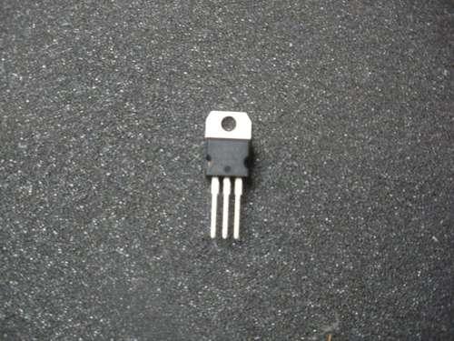
5 Step 3: Transistors, Capacitors, and Optional Vreg Transistors: The silkscreen image shows what direction the transistors go in, you may have to bend the middle lead outwards so it fits into the holes Capacitors: C1 and C3 are both 01uF capacitors, the small yellow ones They can go in either way, not polarized C2 is a 1uF, the line down the side marks the negative lead, make sure that goes into the correct hole The silkscreen shows the positon and a + and - sign Or look at the 2 parallel lines inside the circles, the solid side indicates the negative C4 value varies, 1uF to 220uF, it is polarized goes in the same way as C2 Optional VREG: 7805 Linear Regulator, only needed if the input put voltage is more than 5v, otherwise its holes are jumped and the 7805 is not used If source voltage is greater than 5v - The 7805's placement is indicated on the silkscreen layer, but it should be facing outwards like in the images If the source voltage will be 5v, bend a piece of wire into a U shape, and use it to jump the 2 outer holes together, leave the middle hole alone


6 Image Notes 1 Required for input voltages greater than 5v


7 Step 4: LED Display and Buttons, Wiring This controller has an external 3 digit LED display and 2 buttons to set the modes and address LED Display PCB: Real simple just put it together as shown in the images 2 buttons and the LED display The LED display and buttons are wired to the main controller PCB by some ribbon cable This enables the display and buttons to be mounted away from the main controller Wiring: Using a razor blade, start by splitting the cable about 05" - 1" long, both ends Strip all 1/8" of insulation of each wire, both ends One wire at a time, carefully solder them one after the next to the controller Lay it out flat and place the LED display on the un-soldered end, note where the wires should be soldered The boards are connected to each other the same way they would be if they were lined up next to each other with the holes lining up, face up See image


8
, PWMOUT(4-pin), and Power input(2-pin) If assembling the Regular Version, all connections to and from the PCB will be soldered directly onto the controller")

9 Step 5: Optional Headers Kits are sold as a base type, Full Kit ncludes all the parts shown, including, Panel Mount XLRs both male and female, Headers, Housings, Crimps,(Interconnects) for the controller PCB and wire for the XLR(3-pin), PWMOUT(4-pin), and Power input(2-pin) If assembling the Regular Version, all connections to and from the PCB will be soldered directly onto the controller PCB, no plugs Solder up all your required connections, view Step 6 if you are unsure how to connect the XLRs, otherwise skip to Step 7 Or continue this step if assembling the Full Version Headers pair up with housings and crimps to make it easy to plug or unplug the PWM outputs and power input connectors They are optional, if you are not using them you will just solder the wires directly to the PCB so you can skip this step Please View This Webpage for details of how to use the crimps and install them in the housings Headers: Before soldering them in, note they are polarized and consider any connectors that are already assembled so they will be compatible PWR, 2-pin header is for the power, its a tight squeeze with C4 right there, but it fits XLR-IN, 3-pin is for the DMX connections PWMOUT, 4-pin header is for the 3 PWM outputs and GND reference Image Notes 1 Optional Parts, Comes with the Full kit /w Connectors & Wire Image Notes 1 Kits may include brown or white part 2 Didn't need to install the


10 Step 6: DMX Connector Assembly The optional Panel Mount XLRs kit, comes with one female and one male panel mount XLRs, 12" triple strand wire, and screws for mounting the XLRs Wire Up the XLRs: The XLR's pins are labeled in the plastic on the front Measure out how much wire you will need, try to use as little as possible to reduce interference Connect the XLR pin 1 on the male to the female Connect the XLR pin 2 on the male to the female Connect the XLR pin 3 on the male to the female Run 3 wires from pins 1-3 on either the male or the female If using the option headers and housings, fasten crimps the ends of the 3 wires and place in the housing Otherwise solder the wires directly onto the PCB as shown in the diagram


11 Image Notes 1 Comes with the Headers and Housings kit Step 7: Plug It All In & Test First Look the whole circuit over, check for solder bridges, loose wires, or wrong connections Insert ICs and Test: The end with the dot on the IC lines up with the notch on the end of each socket Line up the pins and press in firmly Check it over Once the chips are inserted and its looked over, go ahead and apply power Remember if no 7805 has been installed 5 volt is the maximum input voltage, if the 7805 was installed, minimum 7 volts are required, up to 32 volts, which could be further increased with a different 7805 and heat sink The display should light up and respond to button commands Once the display has been tested and working, it is a good idea to hot glue the ribbon cable to the PCBs, otherwise the wires could break or come undone while handling Optional: connect to a DMX signal, it should switch from stand-alone to DMX mode, and display the address


12 Image Notes 1 Wire for connecting Power 2 for PWMOut 3 Power Connection Image Notes 1 May be white, no difference Step 8: Utilization - Output Board All designs, schematics and PCBs, of the various types of output boards are available, check Step 1 for a ZIP or on the website There are various ready made current regulators that could be used, Such as BuckPlus 7021/7023 series or the VLD-350/700 constant current regulators Output boards will vary depending on batch, but will function the same Shown here, is the Common Anode Low-Profile Output/Breakout Board It uses 3x logic level MOSFETs to control the colors This board does not limit current, any limiting will have to be done else where, either by wiring a resistor inline with the LED or using pre-assembled modules or strips that have their own resistors The board is small, 15" x 15" x 05" tall Inexpensive and should be able to handle up to 30w per channel or so of LEDs The bottom traces should be tinned if using more than 20 watts total Common Anode Low-Profile: The kit comes with the parts shown and wire Crimps/Housing is optional R4, R5, R6 - Resistors - 10 kohm 1/4w, they go under the MOSFET leads R1, R2, R3 - Resistors ohm 1/6w Q1, Q2, Q3 - MOSFETs - Logic Level, low resistance such as: Bend the MOSFET's over, line the holes up Terminal block, make sure the openings face outwards Connect the Red and Black wires either from the bottom(shown) or through the header holes Connect 4 wires from the TTL Inputs header to the Outputs on the controller Attach crimps and housing if you are using them, otherwise solder directly onto the controller, remove PIC first! Check over the traces and solder points real well


13


14


15 Step 9: Utilization - Build a Light I used an old florescent black light fixture and refitted it with 21 watts of 12v RGB LED Light Strip (6 watts per meter) and this controller to run it I wanted some versatility with how the connections were located, so it could lay down on either side or stand up and there would be access to the DMX in/out and display/buttons It has 2 sets of DMX in and outs on each side, they are all in parallel, nothing special Remember that an output board is selected based on the configuration of the LEDs, any type of LED can be controlled with this controler Contact Us for help choosing a Output Board I forgot to take pictures of a few steps When refitting or building custom lights, everyone will do it differently, but take a look at how this one worked out - Complete and test the controller, this will use a 12v input, so the controller absolutely needs the 7805 installed - After taking the salvaged light apart and gutting it of its old electronics, I test fit the circuit to see where it would fit, the octagon case on the end had plenty of space - Decide where the XLRs will go, DC Power Jack, and the button/display PCB - The spot I wanted the Display wasn't quite big enough, but I was able to trim the PCB down and made it fit - Using the diagram, found on the datasheet or for download, mark the location of where to cut - Cut the display hole first, methods vary greatly, I used a razor as the plastic was pretty weak tried to score and snap the last side and it broke more than I wanted - Drill out the button holes with a 5/16" or so bit, then use a razor to trim it so it can fit the square buttons - Mark and drill holes for the XLRs, use a 7/8" drill bit, spades do work, but be careful - Mark and drill the holes for the XLR's screws - Cleaned the area where the LEDs will go with alcohol - Applied some aluminum duct tape to the cleaned area, it will reflect light and dissipate some heat - Trimmed it with a razor blade - Soldered colored 22ga wire to all the contacts on the 3 strands of RGB Light strip - Apply the 12v RGB LED Light Strip, I did 3 rows, with the 2 on the outside longer than the inner row, with the inner row offset All the wired ends are on the end with the controller - Connected the Output board PWR and Controller PWR to a panel mount barrel jack - Mounted the XLR jacks, and screwed them in - Test fit the display, once I knew it fit, I used hot glue to secure it in place - Positioned the output board away from the rest, and secured it in place - Attached the wires from the RGB light strip to the terminals on the output board - The controller was stuffed in where it could fit, Making sure that the solder contacts on the bottom or top can't possible touch anything - Test it - Cut a 525" by 4775" piece of 50 mil HDPE plastic - Positioned it and drilled 1/8" holes for pop rivets - Used 5 rivets on one side then did the other side, ensuring I kept it tight - Used a small piece of black vinyl to cover up the jaggedness around the display/button holes, and then placed some silver dots on the button locations Used a 3A inline power supply and had it up and running Very bright


16 Image Notes 1 Broke on Accident Image Notes 1 Broke on accident


17 Image Notes 1 Aluminum Tape Image Notes 1 Trimmed up Image Notes 1 Color Coded Wire


18 Image Notes 1 Looks like a mess, but fit just fine Image Notes 1 Did dual XLRs on both sides, incase the device is laying on one side or the other Image Notes 1 Put some vinyl on to make it look good

19 Step 10: Finished Thanks for reading my Instructable, if you have any questions or need any help with this or any of my other kits or Instructables please send me a PM or contact me through My Website Please check out my Instructables Profile or my Projects Page to view all my posted projects Subscribe for future projects Coming soon is a new Chromation Systems 48 Channel LED Controller, 48 Channels of mono-color LEDs or 16 Channels of RGB LEDs, more than 1 LED can be on each channel, It interfaces to computer software through USB The custom software, ColorMotion makes it easy to create and upload endless amounts of patterns With fading, cascading, flashes, sliding effects Great for RGB LED Infinity Mirrors, accent lights, case lights, anytime where dynamic control of multiple RGB LEDs is required Please visit my Chromation Systems Webstore for kits, LEDs, power supplies, and other items
OpenSprinkler v2.2u Build Instructions
 OpenSprinkler v2.2u Build Instructions (Note: all images below are 'clickable', in order for you to see the full-resolution details. ) Part 0: Parts Check Part 1: Soldering Part 2: Testing Part 3: Enclosure
Universal Keying Adapter 3+
 Universal Keying Adapter 3+ The Universal Keying Adapter Version 3+ kit will allow you to key nearly any transmitter or transceiver with a straight key, electronic keyer, computer serial or parallel port
OpenSprinkler v2.1u Build Instructions
 OpenSprinkler v2.1u Build Instructions (Note: all images below are 'clickable', in order for you to see the full-resolution details. ) Part 0: Parts Check Part 1: Soldering Part 2: Testing Part 3: Enclosure
Button Code Kit. Assembly Instructions and User Guide. Single Button Code Entry System
 Button Code Kit Single Button Code Entry System Assembly Instructions and User Guide Rev 1.0 December 2009 www.alan-parekh.com Copyright 2009 Alan Electronic Projects Inc. 1. Introduction... 4 1.1 Concept
BuffaloLabs WiFi Lantern Assembly guide version 1
 BuffaloLabs WiFi Lantern Assembly guide version 1 Needed equipment: Solder iron Solder wire Cutter Wire stripper (optional) Hot glue gun Overview of the components (not including USB cable and box panels)
Building the RGBW LED Controller
 Building the RGBW LED Controller A guide for the assembly and operation of your RGBW LED Controller. ver 3.1 Getting Started Parts list - You should have received the following parts: (1) Circuit Board,
MAIN PCB (The small one)
") THANKS FOR CHOOSING ONE OF OUR KITS! This manual has been written taking into account the common issues that we often find people experience in our workshops. The order in which the components are placed
THANKS FOR CHOOSING ONE OF OUR KITS! This manual has been written taking into account the common issues that we often find people experience in our workshops. The order in which the components are placed
SRI-02 Speech Recognition Interface
 SRI-02 Speech Recognition Interface Data & Construction Booklet The Speech Recognition Interface SRI-02 allows one to use the SR-07 Speech Recognition Circuit to create speech controlled electrical devices.
Advanced Strobe 1.0 Kit
 Kit Instruction Manual Eastern Voltage Research, LLC December 2013, Rev 1 1 http://www.easternvoltageresearch.com Kit Introduction to the Kit Thank you for purchasing the Kit. If you are looking for a
Assembly Instructions (8/14/2014) Your kit should contain the following items. If you find a part missing, please contact NeoLoch for a replacement.
 Your kit should contain the following items. If you find a part missing, please contact NeoLoch for a replacement.") NeoLoch NLT-28P-LCD-5S Assembly Instructions (8/14/2014) Your kit should contain the following items. If you find a part missing, please contact NeoLoch for a replacement. Kit contents: 1 Printed circuit
NeoLoch NLT-28P-LCD-5S Assembly Instructions (8/14/2014) Your kit should contain the following items. If you find a part missing, please contact NeoLoch for a replacement. Kit contents: 1 Printed circuit
[Note: Power adapter is not included in the kits. Users need to prepare a 9 12 V ( >300mA capacity ) DC power supply]
![[Note: Power adapter is not included in the kits. Users need to prepare a 9 12 V ( >300mA capacity ) DC power supply]](/thumbs/76/74094055.jpg "[Note: Power adapter is not included in the kits. Users need to prepare a 9 12 V ( >300mA capacity ) DC power supply]") 062 LCD Oscilloscope Assembly Notes Applicable Models: 06203KP, 06204KP DN062-18v02 Important Notes 1. Some components shown in the schematic and PCB layout are for options or adjustments. They do not
062 LCD Oscilloscope Assembly Notes Applicable Models: 06203KP, 06204KP DN062-18v02 Important Notes 1. Some components shown in the schematic and PCB layout are for options or adjustments. They do not
Installation/assembly manual for DCC/Power shield
 Installation/assembly manual for DCC/Power shield The DCC circuit consists of the following components: R1/R6 R2/R3 R4/R5 D1 C2 2 kω resistor ½ Watt (colour code Red/Black/Black/Brown/Brown) 10 kω resistor
Installing PRO/DGX or Pro Soloist MIDI interface. R Grieb 9/08/2017
 Installing PRO/DGX or Pro Soloist MIDI interface. R Grieb 9/08/2017 Please read these instructions before purchasing the MIDI interface, to make sure you are comfortable performing the necessary steps.
K191 3 Channel RGB LED Controller
 K191 3 Channel RGB LED Controller 1 Introduction. This kit has been designed to function as a versatile LED control module. The LED controller provides 3 high current channels to create light effects for
Morse Code Practice Oscillator
 Features Description Keyer speed range: Limited only by keying source True Sine wave tone output Tone Volume Control Tone Frequency Control Internal Speaker 1/8 External Speaker/Headphone Jack RCA Key
QRPGuys Digital Dial/Frequency Counter
 QRPGuys Digital Dial/Frequency Counter First, familiarize yourself with the parts and check for all the components. If a part is missing, please contact us and we will send one. You must use qrpguys.parts@gmail.com
Part 2: Building the Controller Board
 v3.01, June 2018 1 Part 2: Building the Controller Board Congratulations for making it this far! The controller board uses smaller components than the wing boards, which believe it or not, means that everything
AXE Stack 18. BASIC-Programmable Microcontroller Kit. An inexpensive introduction to microcontroller technology for all ability levels
 Ltd AXE Stack 18 BASIC-Programmable Microcontroller Kit a division of An inexpensive introduction to microcontroller technology for all ability levels Free Windows interface software Programmable in BASIC
Construction Construction Instructions
 Semi-Virtual Diskette SVD Construction Construction Instructions PCB version 2.0 September 2004 Eric J. Rothfus Table of Contents Table of Contents... i Parts List...1 Construction Overview...5 PCB Construction...
Phi-panel backpack assembly and keypad options Dr. John Liu 12/16/2012
 Phi-panel backpack assembly and keypad options Dr. John Liu 12/16/2012 1. Introduction:... 3 Currently available:... 3 2. Backpack assembly... 4 3. Connecting to a keypad... 6 4. Rotary encoder keypads...
KDR00101 DMX Controlled Relay Kit
 KDR00101 DMX Controlled Relay Kit This is a DMX512-A relay kit using ANSI approved RJ-45 connectors for DMX networks. Power requirements are 12 Vdc @ 100 ma. The relay contact rating is 10 Amp @ 120 or
Advanced Lantern 1.0 Kit. Introduction to the Advanced Lantern 1.0 Kit
 Advanced LED Lantern 1.0 Instruction Manual Eastern Voltage Research, LLC Introduction to the Advanced Lantern 1.0 Kit Thank you for purchasing the Advanced Lantern 1.0 Kit. This kit is an advanced microprocessor
RC Tractor Guy Controller V2.1 Assembly Guide
 RC Tractor Guy Controller V. Assembly Guide Features 0 Push button inputs Dual axis thumb sticks with built-in push button Rotary encoders with built-in push button MCU Socket to suit Meduino Mega 560
GLiPIC Ver C Assembly manual Ver 1.0
 GLiPIC Ver C Assembly manual Ver 1.0 Last Rev 1.1 Oct 30, 2001 Author: Ranjit Diol Disclaimer and Terms of Agreement As with any kit, only the individual parts supplied are guaranteed against defects and
KDS Channel DMX Controlled Servo Kit
 KDS00801 8-Channel DMX Controlled Servo Kit This is a DMX512-A controlled servo kit using ANSI approved RJ-45 connectors for DMX networks. Power requirements are 8-20 VDC @ 50 ma. The board features an
Post Tenebras Lab. Written By: Post Tenebras Lab
 Post Tenebras Lab PTL-ino is an Arduino comptaible board, made entirely out of through-hole components. It is a perfect project to learn how to solder and start getting into the world of micro controllers.
EE 354 August 1, 2017 Assembly of the AT89C51CC03 board
 EE 354 August 1, 2017 Assembly of the AT89C51CC03 board The AT89C51CC03 board comes as a kit which you must put together. The kit has the following parts: No. ID Description 1 1.5" x 3.25" printed circuit
KDR00301 DMX Controlled Relay Kit
 KDR00301 DMX Controlled Relay Kit This is a DMX512-A relay kit using ANSI approved RJ-45 connectors for DMX networks. Power requirements are 12 Vdc @ 200 ma. The relay contact rating is 10 Amp @ 120 or
Digital Candle 1.0 Kit
 Kit Instruction Manual Eastern Voltage Research, LLC June 2012, Rev 1 1 http://www.easternvoltageresearch.com Introduction to the Kit Thank you for purchasing the Kit. This kit is definitely a favorite
High Power (15W + 15W) Stereo Amplifier
 Stereo Amplifier") High Power (15W + 15W) Stereo Amplifier Build Instructions Issue 1.0 Build Instructions Before you put any components in the board or pick up the soldering iron, just take a look at the Printed Circuit
High Power (15W + 15W) Stereo Amplifier Build Instructions Issue 1.0 Build Instructions Before you put any components in the board or pick up the soldering iron, just take a look at the Printed Circuit
Onwards and Upwards, Your near space guide. Figure 1. CheapBot Line Follower
 The CheapBot Line Follower is a plug-in single-board sensor for almost any programmable robot brain. With it, a robot can detect the presence of a black or white zone beneath its two sensors. In its simplest
Populating and Installing Synthex Rev 2/3 EPROM adapter board. R Grieb 5/13/2018
 Populating and Installing Synthex Rev 2/3 EPROM adapter board. R Grieb 5/13/2018 Please read these instructions before purchasing or installing the EPROM adapter, to make sure you are comfortable performing
Pacific Antenna Two Tone Generator
 Pacific Antenna Two Tone Generator Description Our Two Tone Generator kit provides two non-harmonic, sine wave signals for testing audio circuits Outputs of approximately 700Hz and 1900Hz and the combination
MAIN PCB (The small one with the square cut out from one side)
") THANKS FOR CHOOSING ONE OF OUR KITS! This manual has been written taking into account the common issues that we often find people experience in our workshops. The order in which the components are placed
THANKS FOR CHOOSING ONE OF OUR KITS! This manual has been written taking into account the common issues that we often find people experience in our workshops. The order in which the components are placed
USB Controlled DMX interface
 USB Controlled DMX interface Control DMX fixtures using a PC and USB interface. Stand-alone test function that outputs all 512 channels at a time, with adjustable levels. Total solder points: 117 Difficulty
Digital Flame 1.0 Kit
 Digital Flame 1.0 Kit Instruction Manual Eastern Voltage Research, LLC June 2012, Rev 1 1 http://www.easternvoltageresearch.com Introduction to the Digital Flame 1.0 Kit Thank you for purchasing the Digital
SharpSky Focuser Construction. SharpSky Focuser. Construction Document V st December 2012 Dave Trewren 1
 SharpSky Focuser Construction Document V0.12 1st December 2012 Dave Trewren 1 Contents 1 General... 3 1.1 Change Record... 3 1.2 References... 3 2 Introduction... 5 3 SharpSky driver installation... 5
BMC24. MIDI TO GATE CONVERTER DOCUMENTATION. This documentation is for use with the "Euro Style" bottom board.
 BMC24. MIDI TO GATE CONVERTER DOCUMENTATION. This documentation is for use with the "Euro Style" bottom board. A. USING THE MIDI TO GATE CONVERTER B. PARTS LIST C. BUILDING INSTRUCTIONS D. SCHEMATICS Revision.
VG-305A AC Traffic Light Controller Kit
 Galak Electronics Electronic kits and components Website: GalakElectronics.com Email: sales@galakelectronics.com Phone: (302) 832-1978 VG-305A AC Traffic Light Controller Kit Thank you for your purchase
LED Knight Rider. Yanbu College of Applied Technology. Project Description
 LED Knight Rider Yanbu College of Applied Technology Project Description This simple circuit functions as a 12 LED chaser. A single illuminated LED 'walks' left and right in a repeating sequence, similar
BehringerMods.com. Instructions for modification of Behringer SRC analog inputs and outputs
 BehringerMods.com Instructions for modification of Behringer SRC analog inputs and outputs The following instructions will cover the details of fully modifying a unit with analog output and analog input
IQ32 Upgrade Kit Assembly Instructions
 IQ32 Upgrade Kit Assembly Instructions Jim Veatch WA2EUJ September 17, 2018 TABLE OF CONTENTS 1. INTRODUCTION... 3 2. IQ-32 UPGRADE KIT INVENTORY... 4 3. PREPARING THE RS-HFIQ AND SIDE PANELS... 6 4. CONNECTING
K8099 NIXIE CLOCK. * optional enclosure TKOK19 (black) - TKOK17 (white) ** optional plexiglass enlcosure B8099 ILLUSTRATED ASSEMBLY MANUAL
 - TKOK17 (white) ** optional plexiglass enlcosure B8099 ILLUSTRATED ASSEMBLY MANUAL") Total solder points: 230 + 74 Difficulty level: beginner 1 2 3 4 5 advanced NIXIE CLOCK K8099 ** * A unique combination of both vintage and modern electronics ILLUSTRATED ASSEMBLY MANUAL H8099IP-1 * optional
Total solder points: 230 + 74 Difficulty level: beginner 1 2 3 4 5 advanced NIXIE CLOCK K8099 ** * A unique combination of both vintage and modern electronics ILLUSTRATED ASSEMBLY MANUAL H8099IP-1 * optional
Chill Interface PCB Assembly Instructions
 ExcelValley Chill Interface PCB Waveblaster Module MIDI Interface Board Chill Limited Edition V2 Assembly Kit Standalone midi interface board for Waveblaster synthesizer modules. Suitable for most Waveblaster
Uzebox Kit Assembly Guide
 Uzebox Kit Assembly Guide V1.3 Page 1 of 18 Revision History Version Date Author Description 1.0 01-Nov-2012 A.Bourque Initial release 1.1 6-Nov-2012 A.Bourque Minor corrections 1.2 28-Jan-2014 A.Bourque
Building the FlipChip Tester
 Building the FlipChip Tester 1. Assembly of the Core Board You will need a fine low-wattage soldering iron and a Voltmeter. Take your time to solder the components on the Core Board. Better to spend a
KAA Watt x 2 Class-D Audio Amplifier Kit
 KAA10021 50 Watt x 2 Class-D Audio Amplifier Kit This amplifier kit uses Texas Instruments TPA3116D2 stereo audio amplifier IC for driving speakers up to 50 watts @ 4 ohm per channel in stereo mode and
K1EL Morse Code Practice Oscillator CPO
 Features This is an oscillator not a Morse keyer Input source can be a keyer or straight key Near Sine wave tone output CPO Tone Volume Control CPO Tone Frequency Control Use headphones or external speaker
LED Sequencer 1.0 / 1.5
 LED Sequencer 1.0 / 1.5 Instruction Manual Eastern Voltage Research, LLC May 2012, Rev 2 1 http://www.easternvoltageresearch.com Introduction to the LED Sequencer 1.0 Thank you for purchasing the LED Sequencer
UF-3701 Power Board Construction Guide
 Page 1/5 Soldering and Part Placement See the Chapter 3 of the MIT 6270 Manual for information on electronic assembly, including soldering techniques and component mounting. Construction Information All
Revised: Page 1
 Brought To You By And Designed By: Revised: 2017-05-07 Page 1 Features Of The Universal PSU Kit: Fits all standard Apple II and /// Power Supply Enclosures. (all parts included, user supplies household
Electronics Construction Manual
 Electronics Construction Manual MitchElectronics 2018 Version 1 07/05/2018 www.mitchelectronics.co.uk CONTENTS Introduction 3 How To Solder 4 Resistors 5 Capacitors 6 Diodes and LEDs 7 Switches 8 Transistors
The Basic Counter. Hobby Electronics Soldering Kit. Instruction Guide
 The Basic Counter Hobby Electronics Soldering Kit Instruction Guide TM For the best outcome, follow each step in order. We recommend reading this guide entirely before you get started. Tools required:
Storage Card Interface Kit
 Storage Card Interface Kit for MultiMediaCards(MMC) and Secure Digital Cards (SD) MMSD3K The MMSD3K is complete development kit interfaced to a SD or MMC card. This board ideal for projects that involve
Single cable kit for the FCB1010
 Single cable kit for the FCB1010 1. What is it? With this kit, you can turn your FCB1010 into a phantom powered floorboard, which can do 2-way MIDI communication over one single cable. After installing
dual bipolar voltage controlled step sequencer DIY ASSEMBLY MANUAL v1.03
 dual bipolar voltage controlled step sequencer DIY ASSEMBLY MANUAL v1.03 Contents Contents... 2 Introduction... 3 Part Sourcing Notes for Non Kit Builders... 3 Eurorack Kit Assembly... 4 Resistors and
Electronics Construction Manual
 Electronics Construction Manual MitchElectronics 2019 Version 3 04/02/2019 www.mitchelectronics.co.uk CONTENTS Introduction 3 How To Solder 4 Resistors 5 Capacitors 6 Diodes and LEDs 7 Switches 8 Transistors
Arduino Panel Meter Clock. By Russ Hughes
 Arduino Panel Meter Clock By Russ Hughes (russ@owt.com) OVERVIEW My father has been a lifelong Ham Radio Operator with a fondness for almost anything with a panel meter. After seeing the Trinket Powered
Introduction 1. Liquid crystal display (16 characters by 2 rows) Contrast dial: turn the dial to adjust the contrast of the display (see page 5)
 Contrast dial: turn the dial to adjust the contrast of the display (see page 5)") Welcome to the GENIE Serial LCD module. Introduction 1 The GENIE Serial LCD module allows GENIE-based projects to display messages on a 16 character by 2 row liquid crystal display (LCD). This worksheet
Welcome to the GENIE Serial LCD module. Introduction 1 The GENIE Serial LCD module allows GENIE-based projects to display messages on a 16 character by 2 row liquid crystal display (LCD). This worksheet
MP3 audio amplifier. Build Instructions. Issue 2.0
 MP3 audio amplifier Build Instructions Issue 2.0 Build Instructions Before you put any components in the board or pick up the soldering iron, just take a look at the Printed Circuit Board (PCB). The components
RC210 Repeater Controller Assembly Manual
 Arcom Communications 24035 NE Butteville Rd Aurora, Oregon 97002 (503) 678-6182 arcom@ah6le.net http://www.arcomcontrollers.com/ RC210 Repeater Controller Assembly Manual Hardware Version 3.3 Reproduction
The GENIE Light Kit is ideal for introducing simple lighting projects, such as an electronic die, a wearable badge or a night-time warning system.
 Introduction 1 Welcome to the GENIE microcontroller system! The GENIE Light Kit is ideal for introducing simple lighting projects, such as an electronic die, a wearable badge or a night-time warning system.
Schematic Diagram: R2,R3,R4,R7 are ¼ Watt; R5,R6 are 220 Ohm ½ Watt (or two 470 Ohm ¼ Watt in parallel)
") Nano DDS VFO Rev_2 Assembly Manual Farrukh Zia, K2ZIA, 2016_0130 Featured in ARRL QST March 2016 Issue Nano DDS VFO is a modification of the original VFO design in Arduino Projects for Amateur Radio by
Nano DDS VFO Rev_2 Assembly Manual Farrukh Zia, K2ZIA, 2016_0130 Featured in ARRL QST March 2016 Issue Nano DDS VFO is a modification of the original VFO design in Arduino Projects for Amateur Radio by
3 pyro output datalogger altimeter with an ATmega 328 microcontroller Kit assembly instructions
 3 pyro output datalogger altimeter with an ATmega 328 microcontroller Kit assembly instructions Version date Author Comments 1.0 29/05/2013 Boris du Reau Initial version Rocket Type Micro-max Model Mid
Figure 1. The completed programming kit List of Parts
 Many NearSys kits are programmed through a three pin header soldered to the PCB. Since a three pin receptacle is not a common termination for a serial cable, this kit contains the parts to make one. In
Microsystems. SCI-6 Sound Card Interface Kit Version 1.09 January 2015
 UM Unified Microsystems SCI-6 Sound Card Interface Kit Version 1.09 January 2015 The SCI-6 interface was designed to be a low cost, high quality interface between your PC s sound card and radio transceiver.
Assembly Guide. LEDs. With these assembly instructions, you can easily build your own SWT16. All required components are included in this kit.
 Assembly Guide With these assembly instructions, you can easily build your own SWT16. All required components are included in this kit. You need the following tools: soldering iron, wire cutter and solder.
PIC Dev 14 Through hole PCB Assembly and Test Lab 1
 Name Lab Day Lab Time PIC Dev 14 Through hole PCB Assembly and Test Lab 1 Introduction: The Pic Dev 14 is a simple 8-bit Microchip Pic microcontroller breakout board for learning and experimenting with
Uzebox Kit Assembly Guide
 Uzebox Kit Assembly Guide V1.7 Page 1 of 21 Revision History Version Date Author Description 1.0 01-Nov-2012 A.Bourque Initial release 1.1 6-Nov-2012 A.Bourque Minor corrections 1.2 28-Jan-2014 A.Bourque
An open-source hardware+software project. For design files and additional documentation, please visit:
 An open-source hardware+software project. For design files and additional documentation, please visit: http://www.evilmadscientist.com/go/diavolino Support: http://www.evilmadscientist.com/forum/ Distributed
GPS Series. Build a GPS Smart Logger. By Michael Simpson. As seen in November 2008 of Servo Magazine Pick up an issue at
 GPS Series By Michael Simpson Build a GPS Smart Logger As seen in November 2008 of Servo Magazine Pick up an issue at www.servomagazine.com I recently did a GPS series covering various GPS modules and
RC-210 Repeater Controller Assembly Manual
 Arcom Communications 24035 NE Butteville Rd Aurora, Oregon 97002 (503) 678-6182 arcom@ah6le.net RC-210 Repeater Controller Assembly Manual Hardware Version 2.5 Reproduction or translation of any part of
RC-210 Repeater Controller Assembly Manual
 Arcom Communications 24035 NE Butteville Rd Aurora, Oregon 97002 (503) 678-6182 arcom@ah6le.net RC-210 Repeater Controller Assembly Manual Hardware Version 3.0 Original Release Date September 13, 2004
Parts List: Part # Tools List: Instructions:
 Parts List: Part # 1 pair of Dayton Audio B652s 300-652 1 Dayton Audio DTA-2 amplifier 300-385 1 MP3 module 320-350 1 7805 +5 VDC voltage regulator 7805 1 12 VDC 2A power supply 129-077 1 2.1 mm panel
Bill of Materials: Picaxe-based IR Control Module Pair PART NO
 Picaxe-based IR Control Module Pair PART NO. 2171014 The IRGEII is an IR (Infra Red) Transmitter and Receiver pair that uses a 38 KHZ frequency of invisible light to communicate simple instructions. The
SM010, Assembly Manual PCB Version 1.0
 180 SM010, Assembly Manual MATRIXARCHATE 16 8 IO SEQUENTIAL MATRIX SIGNAL ROUTER SM010 1 2 1 2 3 4 5 3 4 5 6 7 8 9 10 11 12 6 7 8 9 10 11 12 13 14 15 16 PROGRAM A B C D E F G H f1 f2 20.000 180 SSSR Labs
Creep Cluster Build Document. V5 - November 2018
 Creep Cluster Build Document. V5 - November 2018 Dual triangle oscillators are hard-switched by a fast squarewave. Then the signal goes into a resonant lowpass filter. Sounds vary from deep rumbling drones
Colecovision 5v Memory Mod Installation
 Colecovision 5v Memory Mod Installation The Colecovision suffers from common failure points: the power supply, power switch, and 4116 DRAM. The power supply suffers from poor soldering, the power switch
Adafruit USB Power Gauge Mini-Kit
 Adafruit USB Power Gauge Mini-Kit Created by Bill Earl Last updated on 2017-07-14 11:55:04 PM UTC Guide Contents Guide Contents Overview Assembly Basic Assembly Solder the female connector. Solder the
USBCNC USB Disk Key reader for CNC Controls Machine Mount instructions
 USBCNC USB Disk Key reader for CNC Controls Machine Mount instructions 2008-2015 Calmotion LLC, All rights reserved Calmotion LLC 21720 Marilla St. Chatsworth, CA 91311 www.calmotion.com Introduction This
1/Build a Mintronics: MintDuino
 1/Build a Mintronics: The is perfect for anyone interested in learning (or teaching) the fundamentals of how micro controllers work. It will have you building your own micro controller from scratch on
PARTS LIST 1 x PC Board 36 x 5mm Red LED 36 x 12mm LED Standoff 36 x NPN Transistor 36 x 10kΩ Resistor OTHER PARTS YOU MAY NEED
 PARTS LIST 1 x PC Board 36 x 5mm Red LED 36 x 12mm LED Standoff 36 x NPN Transistor 36 x 150Ω Resistor 36 x 10kΩ Resistor 17 x Mini Toggle on-off 8 x Mini Toggle (on)-off-(on) 1 x 470Ω Resistor 1 x 47µF
Arduino 05: Digital I/O. Jeffrey A. Meunier University of Connecticut
 Arduino 05: Digital I/O Jeffrey A. Meunier jeffm@engr.uconn.edu University of Connecticut About: How to use this document I designed this tutorial to be tall and narrow so that you can read it on one side
AVR-M Rev 5 ASSEMBLY
 AVR-M Rev 5 ASSEMBLY The AVR_M is a very compact self contained Atmel AVR mcu controller board. It includes an onboard serial programmer (via PC com port), an I2C eeprom and can use a Mega163, Mega16 or
Connecting igaging DigiMAG Scales to the Caliper2PC Interface A step by step Guide
 What is an igaging DigiMAG Scale? The igaging DigiMAG are digital linear scales that are easily connectable to the Caliper2PC interface. They consist of two parts, the encoder and the readout unit. The
Assembling the Printed Circuit Board for the EDE1200 Robot
 This board receives instructions from either a CBL2, a LabPro or (with an adapter cable) an original CBL. The board has two 595 shift registers (each providing 8 bits of on-board memory) and two EDE1200
QRPometer Assembly Manual Copyright 2012 David Cripe NM0S The 4 State QRP Group. Introduction
 QRPometer Assembly Manual Copyright 2012 David Cripe NM0S The 4 State QRP Group Introduction Thank you for purchasing a QRPometer. We hope you will enjoy building it and and find it a useful addition to
Phi -1 shield Documentation. Table of content
 Phi -1 shield Documentation Last reviewed on 01/03/11 John Liu Table of content 1. Introduction: 2 2. List of functions: 2 3. List of possible projects: 2 4. Parts list: 3 5. Shield pin usage: 3 6. List
EAS MINI DAQ. INT of JP4 is for internal power from PC EXT of JP4 is for external power - needed for low power laptops
 EAS MINI DAQ Intro EAS MINI DAQ is an 8 channel, 12bit analog to digital converter for the IBM PC, with 4 digital input channels and 7 digital output channels. It connects to the parallel port of your
IR TRANSMITTER BLOK PCB ASSEMBLY INSTRUCTIONS. Copyright EduTek Ltd Rev. 2
 IR TRANSMITTER BLOK PCB ASSEMBLY INSTRUCTIONS Copyright EduTek Ltd Rev. 2 Circuit Details The circuit is shown below with a parts list of components. Check through this list and identify each component.
Lab 0: Wire Wrapping Project: Counter Board
 Lab 0: Wire Wrapping Project: Counter Board September 3, 2008 In this experiment, you will build a simple counter circuit that can be plugged into your breadboard. It will provide a set of TTL output signals
Zero2Go. User Manual (revision 1.03) Wide Input Range Power Supply for Your Raspberry Pi. Copyright 2017 UUGear s.r.o. All rights reserved.
 Wide Input Range Power Supply for Your Raspberry Pi. Copyright 2017 UUGear s.r.o. All rights reserved.") Zero2Go Wide Input Range Power Supply for Your Raspberry Pi User Manual (revision 1.03) Copyright 2017 UUGear s.r.o. All rights reserved. Table of Content Product Overview... 1 Product Details... 3 Package
Zero2Go Wide Input Range Power Supply for Your Raspberry Pi User Manual (revision 1.03) Copyright 2017 UUGear s.r.o. All rights reserved. Table of Content Product Overview... 1 Product Details... 3 Package
TKEY-1. CW touch key. (no electromechanical contacts) Assembly manual. Last update: June 20,
 Assembly manual. Last update: June 20,") TKEY-1 CW touch key (no electromechanical contacts) Assembly manual Last update: June 20, 2017 ea3gcy@gmail.com Updates and news at: www.ea3gcy.com Thanks for constructing the TKEY-1A CW touch key Have
TKEY-1 CW touch key (no electromechanical contacts) Assembly manual Last update: June 20, 2017 ea3gcy@gmail.com Updates and news at: www.ea3gcy.com Thanks for constructing the TKEY-1A CW touch key Have
solutions for teaching and learning
 RKAmp1 Component List and Instructions PCB layout Constructed PCB Schematic RKAmp1 Stereo Amplifier Page 1 Description The RKAmp1 stereo amplifier PCB has been designed around the 2 x 1watt stereo amplifier
W0EB/W2CTX DSP Audio Filter Construction Manual V3.02.1
 W0EB/W2CTX DSP Audio Filter Construction Manual V3.02.1 Manual and photographscopyright W0EB/W2CTX, January 01, 2019. This document may be freely copied and distributed so long as no changes are made and
Thank you for purchasing the RGB Multi-MCU base and driver board from SuperTech-IT and TheLEDCube.com
 CONGRATULATIONS Thank you for purchasing the RGB Multi-MCU base and driver board from SuperTech-IT and TheLEDCube.com In this document, MCU means Microcontroller such as the PIC32, ATmega328P, prototype
3-slot Backplane For RC2014 User Guide
 3-slot Backplane For RC204 User Guide For module: SC6 version.0 Design and Documentation by Stephen C Cousins Edition.0.0, 208-0-7 CONTENTS OVERVIEW...2 PRINTED CIRCUIT BOARD... 4 SCHEMATIC... 6 WHAT YOU
Pacific Antenna Easy TR Switch Kit
 Pacific Antenna Easy TR Switch Kit Kit Description The Easy TR Switch is an RF sensing circuit with a double pole double throw relay that can be used to automatically switch an antenna between a separate
Onwards and Upwards, Your near space guide Overview of the NearSys Two Sensor Temperature Array Figure 1. A complete Two Sensor Temperature Array
 The NearSys Two Sensor Temperature Array is a kit that permits a BalloonSat to measure two separate temperatures. When plugged into a flight computer like the BalloonSat Mini, the flight computer provides
AT42QT101X Capacitive Touch Breakout Hookup Guide
 Page 1 of 10 AT42QT101X Capacitive Touch Breakout Hookup Guide Introduction If you need to add user input without using a button, then a capacitive touch interface might be the answer. The AT42QT1010 and