This manual is for the installation and operation of the DASH2 PRO unit, for detailed instructions on the configuration software please refer to the
|
|
|
- Georgiana Harrison
- 6 years ago
- Views:
Transcription

1 This manual is for the installation and operation of the DASH2 PRO unit, for detailed instructions on the configuration software please refer to the PC based help system. Where relevant a web address for online help is given in this manual for reference to the configuration software.
2 Table of Contents 1 DASH2 PRO INTRODUCTION FEATURES WHAT IS THE DASH2 PRO? WHO IS THE DASH2 PRO DESIGNED FOR? TECHNICAL SPECIFICATION WHAT'S IN THE BOX? DASH2 PRO INSTALLATION PHYSICAL INSTALLATION OF THE DISPLAY UNIT ELECTRICAL INSTALLATION Connector A orientation and 24 Way Cable: Connector B orientation and 19 Way Cable: CONNECTION TO A DATA LOGGER SWITCH INPUTS CONNECTIONS TO THE VEHICLE WIRING HARNESS Indicators/hazard warning lights Main beam warning light Brake warning light Fog light warning Alternator charge warning Sidelight input Wheel speed input Low level engine speed input High level engine speed input ANALOGUE INPUTS OUTPUT DRIVERS ACCELEROMETER CONFIGURATION GETTING STARTED WITH THE DASH2 PRO WIRING THE UNIT IN TO THE VEHICLE CONNECT THE POWER CONNECT ANY REQUIRED SENSORS TO ANALOGUE INPUTS CONNECT THE CONTROL BUTTONS TO THE UNIT CONNECT UP ANY OUTPUT DRIVERS BEING USED CONNECT TO THE VEHICLE WIRING HARNESS CONFIGURING THE DASH2 PRO FOR THE FIRST TIME SETTING UP THE DASH2 PRO FROM A PC UPLOADING CONFIGURATION DATA TO THE DASH2 PRO Directly from the PC Through a data logger DASH2 PRO DEFAULT CONFIGURATION CONFIGURATION SETS RPM SCALE SHIFT LIGHTS ANALOGUE INPUTS WHEEL SPEED AND RPM INPUT UNIT CONTROL INPUTS GEAR INDICATOR VARIABLE SOURCE
3 8.9 SPEED READOUT OUTPUT SERIAL DATA ALARMS RESET VARIABLE GROUP DATA LOGGING SET UP DISPLAY OUTPUT DRIVERS LAP TIMING CAR COMPUTER FUNCTIONS SET UP DISPLAY AREAS Screen Screen Screen Screen Screen DASH2 PRO GENERAL OPERATION MENU STRUCTURE PERFORM ACTION WARNING REVIEW REVIEW SESSION SELECT CONF SET CONFIGURE Lap Timing TEST Internal data channels MAIN DISPLAY FEATURES GPS signal indication Logger status Max/Min indication Rev counter scale Rev counter Shift lights Vehicle speed or lap counter Gear indicator OUTPUT DRIVER STATUS Serial / CAN input status Information sections Indicator / hazard warning Main beam warning Brake warning Alternator charge warning Fog light warning Odometer / trip warning CHANGING DISPLAYED INFORMATION STARTING AND STOPPING A DATA LOGGER FROM THE DASH2 PRO PROGRAMMING SOFT BUTTONS REVIEWING MAXIMUM AND MINIMUM DATA VALUES RESETTING A MONITORED VALUE TO ZERO FOR CHANGE MEASUREMENT SELECTING DRIVER AND MODE FROM THE DASH2 PRO DATA LOGGING AND LAP TIMING ON THE DASH2 PRO Data logging on the DASH2 PRO LAP TIMING ON THE DASH2 PRO Using an external data logger to do lap timing, and the DASH2 PRO to display the times Using an external data logger to supply GPS data, and the DASH2 PRO to log the data and generate the lap times
4 Using internal GPS and internal data logging All modes of operation: SETTING UP THE DISPLAY FOR LAP TIMING ADDING TRACK MARKERS FROM THE DASH2 PRO OR DL1/DL ADDING TRACK MARKERS FROM THE ANALYSIS SOFTWARE LAP MARKER FILES ON THE DASH2 PRO INTERNAL MEMORY FREQUENTLY ASKED QUESTIONS DASH2 PRO SOFTWARE THE CONFIGURATION TOOL HOW DO I HOW DO I RE-FLASH MY DASH2 PRO? HOW DO I ENTER MY OWN CHANNEL NAMES FOR SENSORS ON THE DASH2 PRO? HOW DO I FIND OUT ABOUT NEW FIRMWARE RELEASES FOR MY RACE TECHNOLOGY PRODUCT? HOW DO I FIND OUT ABOUT/DOWNLOAD NEW SOFTWARE RELEASES? HOW DO I SET UP THE SPEEDOMETER ON MY DASH2 PRO? HOW DO I SET AN ALARM LEVEL ON THE DASH2 PRO? HOW DO I SET UP WHAT IS DISPLAYED ON THE DASH2 PRO? HOW DO I CONNECT A SENSOR TO THE DASH2 PRO? CONNECTING A WHEEL SPEED SENSOR HOW DO I CONNECT MY FUEL LEVEL SENDER HOW DO I CONFIGURE THE RPM ON MY DASH2 PRO? HOW DO I SET UP THE GEAR INDICATOR ON THE DASH2 PRO? HOW DO I CONNECT A 1 OR 2 WIRE SENSOR TO THE DASH2 PRO Choosing a value for the pull up resistor CONNECT AND SET UP A GOPRO INTERFACE CABLE

5 1 DASH2 PRO Introduction 1.1 Features Robust, die cast zinc alloy enclosure, sealed to IP64 High contrast, non-reflective, high visibility custom LCD display with EL backlight 19 and 24 way Binder 423-series connectors Compatible with the DL2, DL1, and SPEEDBOX products 6 configurable dual colour red/green shift lights 4 stand-alone analogue inputs Wheel speed input for vehicle speed and odometer reading Non-resettable odometer Resettable trip meter High and low level engine speed inputs Twin independent 5v reference outputs Configurable peak RPM hold Gear indicator GPS signal strength indicator Max/min recall with reset 5 configurable high/low alarms 5
6 Connections for optional external buttons to control operation Easily configurable with supplied PC software Warning lights for main beam, indicators, brakes, alternator output and fog light Display in mph or kph and miles or km 5 user configurable data display screens USB port for configuration and data download (data download requires data logging option) The following are available as options for the DASH2 PRO Complete setups for 3 drivers and 3 modes Advanced filtering and channel mapping options Extra 4 analogue inputs to bring the total to 8 Advanced alarm and trip computer functions, including monitoring engine hours and laps of fuel remaining 4 low side on/off output drivers Upgrade output drivers to full PWM output Data logging with GPS and accelerometers for single unit lap timing / data logging Second serial port for connecting to further Race Technology data loggers or ECU interfaces CAN receive option for up to 105 CAN reception channels, directly mapped to processed data channels Second CAN port The DASH2 PRO can be combined with other Race Technology products such as data loggers or ECU interfaces to expand the IO capacity should more channels or higher sample rates be required. 6

7 1.2 What is the DASH2 PRO? The DASH2 pro is a fully street legal, compact, water resistant data display system designed for standalone use as a dashboard / lap timer / data logger in either closed or open vehicles. The DASH2 PRO has four analogue inputs as standard, typically used for water temperature, fuel level, oil pressure and oil temperature. There are also inputs for wheel speed sensor and engine speed measurement to make the system in to a fully road legal dashboard, with warning lights included for indicators, brakes, fog light and headlamp main beam, as well as a non-resettable odometer with trip counter, the DASH2 PRO is also an ideal display system for use on road-going cars. With the optional data logging and analogue input extensions the DASH2 PRO can be used as a full 8 analogue input data logger, complete with GPS and accelerometers built in to the unit. All channels can be set up with alarms (5 alarms) so they do not need to be monitored continuously by the driver. When connected to an external data logger or ECU interface many more channels become available for monitoring and logging. Logged data is stored on an internal memory card and downloaded to a PC over a USB interface. Four remote buttons control the DASH2 PRO, three of which can be programmed to provide functions such as resetting monitored values to look for changes, resetting the trip meter, viewing maximum or minimum values, etc. The lap timing features of the DASH2 PRO enable viewing of best lap and sector times after a run, as well as live lap and sector times with predictive timing and live updates of the timeslip to see continuosly how much faster or slower the current lap is compared to the reference lap. An optional system of advanced alarms and driver information can give information such as how many laps of fuel are remaining, or how much time the engine has spent above a certain RPM limit. 7
8 1.3 Who is the DASH2 PRO designed for? The DASH2 PRO is designed for anyone wanting a compact yet feature-packed dashboard. From road cars that never see a race track through to single-seater racing applications, the DASH2 PRO displays all the information required by the driver in an extremely compact yet clear and easily read format. NOTE: Not all options will be available at product release 2 Technical Specification Display Controls Power Supply Requirements Reference outputs Case Construction Connector Type 808 segment customised HTN high contrast, non-reflective, EL backlit LCD 4 optional external buttons 12v nominal input, minimum of 10v, maximum of 28v. Current consumption approximately 250mA Dual 5v 500mA internally monitored reference outputs Die cast zinc alloy, sealed to IP64 1 x 19-way, 1 x 24-way Binder 423 series circular multi-pole connectors Main Processor 150MHz TI DSP Serial Port CAN Port Configured to receive Race Technology format serial data. Optional second serial port for receiving data from multiple systems OPTIONAL receive up to 105 channels mapped to Race Technology data channels for storage, retransmission, or data logging. 11 or 29 bit addressing, up to 1Mbit. Analogue inputs Ignition in Signal (High Level) Ignition in Signal (Low Level) Low side driver outputs OPTIONAL second CAN port 4 analogue inputs (option for extra 4). 0-20v input, 12 bit. Resolution 5mV Maximum sample rate 100Hz Designed to connect directly to negative terminal of ignition coil. Can also fire from fuel injectors and from CD ignition systems. Triggering voltage requires a low input of <1v and a high input of >4v and 15v maximum. Suitable for connection directly to most ECU tacho outputs. Maximum input frequency >300Hz. OPTIONAL 4 low side drivers, each capable of driving 500mA. OPTIONAL upgrade to PWM outputs for Hz PWM drivers 8
9 USB Port Data Logging GPS input Accelerometer Connection for configuration and downloading of logged data OPTIONAL Log all CAN / Serial / internal channels. Maximum logging capacity 2GB. Downloaded over USB SMA connector, 3.3v active antenna. OPTIONAL 3 axis, precision digital output. Guaranteed 2g minimum full scale on both axes. Resolution of 0.005g. Optional 6g sensor available as a factory option. Temperature Factory tested from -20 C to 70 C 9
10 3 What's in the box? Please take a few moments to ensure that you have received all of the following components: DASH2 PRO Harness with one CONN1 and one CONN2 connector, with 9 way d-type connectors for serial and CAN connections and a USB connection for the PC connection. USB A-B cable, to enable connection to a PC for configuration Instruction manual Comprehensive software CD Printed mounting template Carrying case with cut foam interior 4 DASH2 PRO Installation This section will guide you through the various aspects of setting up the DASH2 PRO. Although any aspect can be done at any time, they are structured in a sensible way so that the basics are done first before moving on to the more advanced features. Physical Installation of DASH2 PRO (section 4.1) Electrical Installation (section 4.2) Connection to Data Logger (section 4.3) Switch Inputs (section 4.4) Connection to Vehicle Wiring Harness (section 4.5) Analogue Inputs (section 4.6) Output drivers (section 4.7) Accelerometer configuration (section 4.8) 4.1 Physical installation of the Display Unit The DASH2 PRO must be securely mounted onto flat surface or suitable bracket. When deciding on a mounting location it is important to position the viewing angle for the best display contrast. The display can be clearly read over a wide range of incidence angles, but it is most clearly viewed from an angle of approximately above the display axis. A printed template has been provided and should be used to check that there is sufficient space for mounting the unit. There should also be room for drilling the clearance holes for the fixing screws, the electrical connections and the GPS connector. All three mounting holes should be used to prevent the unit from loosening under vibration. In addition, the use of a low strength, thread locking compound is recommended for installations in a high vibration environment. Mounting requires M4 fasteners with a thread engagement depth of 5mm. Avoid over tightening the mounting screws to prevent thread damage. 10

11 4.2 Electrical installation Due to its wide range of features, the DASH2 PRO can be connected in many different configurations. The unit is supplied with a wiring harness consisting of one 19-way connector and one 24-way connector to attach to the back of the DASH2 PRO, two serial connectors for connection to data logger / ECU interfaces / PC, two CAN interface connections, and an array of flying leads for connection to the power supply, vehicle harness and external sensors. Figure 1 illustrates all DASH2 PRO connections. Depending on your particular application and the features of the DASH2 PRO that you wish to make use of, it may not be necessary to make all of the connections shown. The connector pin assignments and connector orientations are given in Table 1, Figure 2 and Figure 3 respectively. The wiring up of the unit should only be entrusted to competent persons familiar with vehicle wiring installations, as incorrect installation may result in both a risk of fire and damage to the DASH2 PRO unit. THE DASH2 PRO WARRANTY DOES NOT COVER DAMAGE CAUSED BY INCORRECT CONNECTION. The flying leads from the DASH2 PRO harness should be connected to the appropriate leads on the vehicle wiring harness using suitable connectors and with reference to the vehicle circuit diagram. Check the output configuration of any external sensors before connecting these to the DASH2 PRO wiring harness to avoid causing damage to the DASH2 PRO or to the sensor. Figure 1: DASH2 PRO Electrical connections 11
12 NOTE: All connections to the DASH2 PRO should be made with the power supply disconnected. The ends of any unused cables on the DASH2 PRO wiring harness should either be insulated with the cables coiled and secured in a safe manner, or trimmed back and removed altogether. NOTE: As indicated in Figure 1, the DASH2 PRO is provided with its own power input and ground connections. These should normally be connected directly to a 12V power supply. Table 1: Connector Pin Assignment Conn. Pin Description Range Wire Colour No 1 Analogue input V White 2 Analogue input V Black 3 DOWN switch input 0v to activate Red/Black 4 UP switch input 0v to activate Slate 5 Analogue input V Blue 6 Analogue input V Green 7 Switch Ground Yellow 8 5v Reference #2 +5v 500mA Brown 9 MENU switch input 0v to activate Red 10 SELECT switch input 0v to activate Orange 11 USB GND 12 USB 5V 13 USB D- 14 CAN 1 L 9 way d-type pin2 Red 15 RS232 GND 9 way d-type pin 5 Screen 16 RS232 GND 9 way d-type pin 5 Screen 17 RS232 2 Rx 9 way d-type pin 2 Red 18 RS232 1 Tx 9 way d-type pin 3 White 19 CAN 2 L 9 way d-type pin 2 Black 20 CAN 1 H 9 way d-type pin 7 White 21 USB D+ 22 CAN 2 H 9 way d-type pin 7 Green 12
13 23 RS232 1 Rx 9 way d-type pin 2 Red 24 RS232 2 Tx 9 way d-type pin 3 White 1 A Analogue input v Black Low side output 1 500mA 2 B Analogue input v Brown/Black Low side output 2 500mA 3 C Gnd 0v Red/Black 4 D +12v supply 10-20v Figure 8 cable Black / white 5 E Gnd 0v Figure 8 cable Black 6 F High level RPM 0-400v Orange/Black 7 G High level RPM GND 0v Yellow/Black 8 H Main Beam 12v to activate Green/Black 9 I 5v Reference #1 5v 500mA Blue/Black 10 K Alternator warning 100 Ohms to 12v Slate/Black 11 L Brake warning 0v to activate White/Black 12 M Analogue input 8 Low side output v 500mA Brown 13 N Analogue input 7 Low side output v 500mA Red 14 O Sidelight input 12v to activate Orange 15 P Low level RPM input 0-12v square wave Yellow 16 R Right Indicator input 12v to activate Green 17 S Left indicator input 12v to activate Blue 18 T Wheel speed input 0-12v square wave Slate 19 U Fog warning 12v to activate White 13
14 4.2.1 Connector A orientation and 24 Way Cable: Figure 2: Connector A Orientation 14
15 4.2.2 Connector B orientation and 19 Way Cable: Figure 3: Connector B orientation 15
16 NOTE: Please take special care to ensure correct orientation relative to connector keyway when identifying connector pins 4.3 Connection to a data logger The DASH2 PRO can be connected to external devices to give more sensor information for display and logging. This information could come from any of the following sources: DL1 (any variant) DL2 SPEEDBOX ECU Interface OBDII interface External CAN systems (using one or both optional CAN ports) As standard the system has a single RS232 interface for connection to these units. A second serial port and two optional CAN ports are available. 4.4 Switch inputs Four buttons should be connected to the DASH2 PRO to allow in-vehicle control of many functions and display options. These buttons are required to set certain display functions and options, as described in section Momentary push-to-make buttons should be used. These are available from Race Technology or from any good electrical or automotive component supplier. Each button must be wired with one terminal connected to the switch Ground and the other terminal connected to the relevant DASH2 PRO switch input. The Switch Ground pin and four switch input pins are all included in Connector 1, as shown below. Pin No Description Range Wire Colour 3 DOWN switch input 0v to activate Red/Black 4 UP switch input 0v to activate Slate 7 Switch Ground Yellow 9 MENU switch input 0v to activate Red 10 SELECT switch input 0v to activate Orange 16
17 4.5 Connections to the vehicle wiring harness Indicators/hazard warning lights The warning lights for the indicators and hazard lights are activated by applying 12v to Connector B, pins 16 and 17 (right and left indicators, respectively) as identified in Table 1. These should normally be connected directly to the vehicle wiring loom between the indicator switch and the indicator itself. The brightness of the LEDs will vary depending on the status of the sidelight input. This feature is included to dim the indicator warning lights at night to avoid dazzling the driver, yet allow them to be clearly visible during daylight hours Main beam warning light The main beam warning light is activated when 12v is applied to Connector B, Pin 8, as shown in Table 1. This is usually achieved by connecting to the vehicle wiring loom between the headlight switch and the main beam bulb(s) Brake warning light The brake warning light is activated when 0v is applied to Connector B, Pin 11, as shown in Table 1. This is usually achieved by connecting directly to the handbrake warning switch and/or low brake fluid warning switch at the appropriate point in the vehicle wiring harness Fog light warning The fog light warning is activated when 12v is applied to Connector B, Pin 19, as shown in Table 1. This is usually achieved by connecting to the vehicle wiring loom between the fog light switch and the fog light itself Alternator charge warning This warning lamp is illuminated when alternator output is low and the vehicle battery is not being charged. This will be the case when the ignition is turned on but the engine is not running, or if there is an alternator fault. To make use of this feature, Connector B, Pin 10 should normally be connected to the field/alternator warning terminal on the alternator, via the relevant cable in the vehicle wiring harness. There is a 100 ohm resistor inside the DASH2 PRO to provide the required drive to the field on the alternator Sidelight input The sidelight input is used to alter the brightness of the shift lights and indicator/hazard warning lights. This requires Connector B, Pin 14, as shown in Table 1, to be connected directly into the vehicle wiring loom between the sidelight switch and the sidelights themselves. When the input to this pin is at 0v the shift and indicator/hazard warning lights will be bright, but when the input to this pin is at 12v the shift and 17
18 indicator/hazard warning lights will be dimmed slightly. The brightness of the shift lights can also be adjusted independently, as described in section Wheel speed input Wheel speed input data are used by the DASH2 PRO for the vehicle speed, odometer and trip recorder displays, and for gear indicator calculations. This input requires a 5v or 12v square wave signal applied to Connector B, Pin 18, as listed in Table 1. This output format is normally provided by a standard vehicle wheel speed sensor. If not already fitted, these are available from Race Technology or from any good electrical or automotive component supplier. There is no conditioning on this input for a VRS sensor. The input has an internal pull down to ground so the input can be activated by a simple switch to either 5 or 12v. The procedure for configuring this input to the correct pulse rate per distance travelled is described in section Low level engine speed input The low level engine speed input can be used with the DASH2 PRO in standalone mode or with a data logger connected, to give an engine RPM input reading. This information is also used in the gear indicator calculation as well as for the shift light operation. This channel requires a 5v or 12v square wave input applied to Connector B, pin 15 (P), as show in Table 1. IT MUST NOT BE CONNECTED DIRECTLY TO THE IGNITION COIL OR AN INDUCTIVE PICKUP FROM THE HIGH TENSION SIDE OF THE IGNITION SYSTEM. This channel should normally be connected to the engine speed output channel from the engine management ECU High level engine speed input The engine speed input can be used with the DASH2 PRO in standalone mode or with a data logger connected, to give an engine RPM input reading. This information is also used in the gear indicator calculation as well as for the shift light operation. This channel requires high level pulse from the low tension side of an ignition coil or from an injector driver. The main signal must connect to connector B pin 6 (F) and a ground connection physically close to the signal pickup location must be connected to the high level RPM ground, connector B pin 7 (G). 4.6 Analogue inputs The DASH2 PRO is provided with four analogue input channels. A further four can be purchased as an optional extra. These are in addition to any analogue inputs provided by connection to a data logger. Typically these are used to monitor fuel level, water temperature and oil pressure, via existing sensors. If sensors are not fitted, standard sensors are available from Race Technology. The sensor outputs should be connected to the DASH2 PRO analogue input channels on Connector B, Pins 1,2,12,13, as listed in Table 1. THE MAXIMUM INPUT VOLTAGE APPLIED TO THESE CHANNELS MUST NOT EXCEED 20V! The input voltages will need scaling to 18
19 display the correct readings for the physical parameters being measured. This configuration is carried out using the DASH2PRO configuration software Output Drivers There are four optional output drivers for the DASH2 PRO, the connections for these are shared with the optional analogue inputs 5-8 which are part of the same option package. Pin No Description Range Wire Colour 1 A Analogue input 5 Low side output 1 2 B Analogue input 6 Low side output 2 12 M Analogue input 8 Low side output 4 13 N Analogue input 7 Low side output v 500mA 0-20v 500mA 0-20v 500mA 0-20v 500mA Black Brown/Black Brown The output drivers are each capable of sinking up to 500mA and are designed to drive relays or lights which are connected to 5v or 12v. The outputs must be connected like this: Red 19
20 4.8 Accelerometer configuration Before the accelerometers in the DASH2 PRO can be used, they need to be set up for the particular mounting angle of the DASH2 PRO. To zero the accelerometers for this, with the DASH2 PRO in the normal mounting orientation for when it is to be used, select menu 6 Configure, followed by option 6.4 Zero accels. This will then set the accelerometers up correctly and store the results. 5 Getting started with the DASH2 PRO This is a brief introduction to setting up and using the DASH2 PRO for the first time, it details the individual steps required for a standard vehicle installation, for a more detailed guide to each of the stages see the main sections of the DASH2 PRO documentation. 5.1 Wiring the unit in to the vehicle The wiring required will depend on the installation, but the following are very standard 5.2 Connect the power Connector B, figure 8 cable. Make sure this is connected to a fused (500mA) 12v supply 5.3 Connect any required sensors to analogue inputs 1-4 Connector A, pins 1,2,5,6. If a voltage reference is required use pin 8 for 5v reference. For temperature sensors see the following section on the RT knowledgebase. For fuel level sensors see the following section: Connect the control buttons to the unit Connector A pins 3,4,9,10, 7 for switch common. More information is available at: If using a data logger or serial interface, connect this to serial port Connect up any output drivers being used Connector B pins 1,2,12,13 More information on connecting these up is available here: 20
21 5.6 Connect to the vehicle wiring harness This is for day/night control, alternator warning and light warnings, more information is available here: Access to the USB connector will be required for configuring the unit. 6 Configuring the DASH2 PRO for the first time The unit will have been delivered with a default configuration as shown in section 8. It is very likely that changes will be required to the default configuration. To set the unit up for the first operation the following must be checked. If the wheel speed is coming from a wheel speed sensor, set up the number of pulses per mile. More information is available here: If using the fuel level sensor calibrate it correctly. (see section 12.10) If using an ECU interface, set up the RPM data to come from the serial port. Information is available here: If the RPM data is not coming directly from an ignition coil, but is coming from an ECU tacho output, set up the RPM to come from the low level RPM source. Information is available here: Configure the RPM display to show the maximum RPM you require. Configure the shift lights. Correctly configure the gearbox, final drive and wheel circumference data for the gear indicator. 21
22 Set the level for the high water temperature alarm. (See section 12.6) If required, set up a warning for low fuel alarm. If required, set up the unit for data logging (see section ) If you are using the internal accelerometers, read the following section: 7 Setting up the DASH2 PRO from a PC Almost all of the configuration settings on the DASH2 PRO can be configured from a PC. Five user-configurable screens are available, each displaying three sensor input channels, enabling up to fifteen variables to be viewed in total. Up to five channels can be monitored for alarm conditions. As well as selecting which data is viewed and setting the alarm limits, the configuration software is also used to set the scaling on each input channel, and to set up the RPM display options and gear indicator calculations. The DASH2 PRO is supplied with a default configuration suitable for many typical applications. This will allow display of all the basic features after connection to the vehicle wiring harness (see section 4.5). To make custom configuration changes, full operating instructions for the configuration software is available from the Race Technology Online Help System: Operating instructions are also included on the CD provided with the DASH2 PRO. Simply follow the path: Software\Configuration and reflash\configuring display products. 7.1 Uploading configuration data to the DASH2 PRO Once changes have been made with the configuration program, the new settings require uploading to the DASH2 PRO. This can be done either by a direct connecting through the USB port on the DASH2 PRO or by sending the configuration from a DL1 CLUB/PRO/WP Directly from the PC This requires connection of the DASH2 PRO USB port to the PC and for the DASH2 PRO to have power. Full instructions for uploading the new configuration to the DASH2 PRO are provided in the Race Technology Online Help System by following the path: Software\Configuration and reflash\configuring display products. 22


23 7.1.2 Through a data logger After completing all changes in the configuration software, click on the File / Save Configuration option. The DASH2 PRO.CMG file must then be saved on to the memory card and the card inserted in the data logger. The DASH2 PRO stores all configuration settings, so there is no need to repeat this procedure each time the unit is powered-up, unless making changes to the existing configuration. This method will not work with a DL1 MK1 / MK2 / SPORT. If using one of these data loggers the configuration must be done directly from the PC. 8 DASH2 PRO default configuration The default configuration for the DASH2 PRO is as follows: 8.1 Configuration sets All nine configurations are identical 8.2 RPM scale 8.3 Shift lights 23


24 8.4 Analogue inputs 8.5 Wheel speed and RPM input 8.6 Unit control inputs 24


25 8.7 Gear Indicator 8.8 Variable source Everything except the data from the four internal analogue channels and RPM is set to come from any serial port. 8.9 Speed readout 25


26 8.10 Output serial data Serial output data set at a slow rate for checking on a PC 8.11 Alarms High level alarm set to 100 degrees C on water temperature 26

27 8.12 Reset Variable group No variables set 8.13 Data logging All channels enabled for logging at maximum rate File name set to RUN rr Directory name set to RTyymmdd 8.14 Set up display 8.15 Output drivers All disabled. 27


28 8.16 Lap timing 8.17 Car computer functions 28


29 8.18 Set up display areas Screen 1 29
30 Screen 2 30

31 Screen 3 31


32 Screen Screen 5 Disabled 32
33 9 DASH2 PRO General operation There are four buttons attached to the DASH2 PRO, three of these buttons (Up, Down, Select) can be set to perform a number of different functions based on the settings in the configuration software, the fourth button (Menu) will always take the user in to the main menu. From the main menu custom settings can be made for setting up the display brightness/contrast, functions which would normally be assigned to buttons can be performed, and the currently set Driver / Mode can be changed. If an alarm is being shown on the display then pressing any button will clear the alarm. If logging data on the internal memory, going in to the memory will stop the data logging. For the other functions which can be performed directly from the menu on the DASH2 PRO see the sections below. Perform Action (section 9.2) Data Logging and lap timing on the DASH2 PRO (section 9.16) Warning Review (section 9.3) Review Session (section 9.4) Select Conf Set (section 9.5) Configure (section 9.6) Test (section 9.7) 33

34 9.1 Menu structure Figure 4: Menu Structure 34
35 9.2 1 Perform Action All of the standard functions which can be assigned to a button can be carried out from here. For the full list of functions available see the following webpage: Warning Review This is not yet implemented, more details to follow Review Session After finishing a session of driving the fastest lap, fastest sectors and individual lap and sector times can be displayed. From menu 4 select Current Session, which will display the date and time of the current session, then scroll through to select to view the individual details. Fastest Lap: When this menu is displayed the screen will show the fastest lap time along with which lap the time was produced on. Pressing 'Select' to view the details will enable viewing of each individual sector within the lap to show the sector time around the lap, along with the maximum and minimum speed for each sector. Pressing 'select' or 'menu' will go back up a menu level to enable selecting of other data. Fastest Sectors: This works in exactly the same way as the Fastest Lap section in terms of viewing the data for each sector, except that instead of showing the sector times for each sector from one lap they are shown from the fastest individual sectors. View All Data: As above, but will scroll through the data for each sector in term, showing the times and speeds for each individual sector and then the times for the full lap at the end. For two laps of data with three sectors per lap the data would be shown as: Lap 1 Sector 1 Lap 1 Sector 2 Lap 1 Sector 3 Lap 1 Lap 2 Sector 1 Lap 2 Sector 2 Lap 2 Sector 3 Lap Select Conf Set Select menu 5.1 to choose which of the three drivers should be active at the moment, Select menu 5.2 to select which of the three modes for the selected driver are active. 35
36 This will override any options set in the main configuration software on the PC to select operating mode Configure Select menu 6 to override some of the configurations which are set on the PC, this can be particularly useful for setting up preferences on shift lights and LCD settings which cannot be determined easily from the PC, as well as setting up options for the lap timing data. 6.1 Lap Timing 6.2 Display Contrast: Select to adjust the contrast on the display. As the contrast value is adjusted on the screen the effect will be shown immediately on the display 6.3 Brightness: Select this to adjust the day and night brightness for the LEDs as well as the day and night brightness for the LCD back light. 6.4 Zero accels: If the DASH2 PRO is not mounted vertically there will be an offset on the accelerometers Lap Timing There are various options which can be set for the lap timing functions. The majority of these will only function when the data logging option is enabled and are not yet implemented Lap Reset Value: When the lap counter is set to count down rather than up from the PC configuration software, this is the value which the lap counter is reset to Use Data Marks: Not yet implemented Use Data As Ref: Not yet implemented Auto Select: Not yet implemented Load Lap Data : Not yet implemented Delete Lap Data: Not yet implemented 36
37 9.7 7 Test This menu will show the firmware / bootloader / configuration software details for the DASH2 PRO, allows testing of the output drivers (if enabled) as well as looking at the raw data on any of the data inputs. 7.1 Dash info When selected scroll through the information using the Up and Down buttons to view: Hardware version number Firmware version number Bootloader version number If locked to a data logger, the logger serial number Information on any options which are enabled 7.2 Show data Select to view data from either of the two serial ports, for the two CAN ports or for the internal sensors and 7.2.2, serial ports 1 and 2 For either of the serial ports the data will show in the following format: C 123 RAW CAL * NAME If the select button is pressed the data will toggle to show: C 123 FREQ COUNT NAME C is the incoming serial data channel number which the data is derived from, the number underneath is the internal channel reference number. RAW is the raw channel value as it comes in without any scaling applied, the value under CAL is the calculated value after any scaling or filtering has been applied. The * is shown if the data is actually being used. I.E. the data is mapped to a used channel. The name is the assigned variable name FREQ is the frequency of the incoming data, COUNT is the total number of samples received. Pressing the up or down button will go forwards or backwards through the list of channels. Only channels which are present in the data stream will be shown. Pressing and holding the UP or DOWN button will scroll quickly through the list and 7.2.4, CAN ports 1 and 2 Data view not yet implemented 37
38 7.2.5 Internal Data Channels 7.4 Test Outputs This is used to trigger the four outputs on the unit. VOLT OFF 12.4 OUTPUT 1 VOLT is the current voltage being read back from the pin, OFF shows that the output is currently turned off, pressing the select button will turn the output on for as long as select is pressed. When this happens the reading on the VOLT output should go down to zero. Pressing the UP/DOWN button will scroll through the four output channels. The use of this test overrides any of the configurations with regards to whether these pins are set as outputs or not. 7.6 Demo mode When selected this toggles the demo mode. Demo mode scrolls through screens of data and shows warning on the screens, along with activating the shift lights and activating the bar graph Internal data channels Scroll through the values from the build in sensors, where available. ACCEL X ACCEL Y ACCEL Z REF 1 REF 2 GPS WHEEL SPEED RPM LOW RPM HIGH ADC 1 ADC 2 ADC 3 ADC 4 ADC 5 ADC 6 ADC 7 ADC 8 38
39 Accelerometer data X,Y,Z RAW CAL OFF * ACCEL X This shows the raw, calibrated, and current calibration offset values for the X accelerometer The * shows if this value is actually being used. This would be repeated for the Y and Z accelerometers Internal reference voltage levels REFERENCE 1 and 2 RAW CAL ON REFERENCE 1 The RAW and CAL are the raw and calculated values from reading the output of the reference on the feedback. ON shows that the output is currently on. If the output is off then it will show OFF and the readings from the RAW and CAL values will show what is being read back from the pin as both a raw ADC reading and as a processed voltage. GPS VEL POS ALT GPS VEL is the velocity accuracy, POS is the positional accuracy, ALT is the altitude accuracy, This is intended to show that the GPS unit is doing something and see what the accuracy figures are. WHEEL SPEED RAW CAL * WHEEL SPEED RAW is the raw frequency values read from the wheel speed input, CAL is the calibrated value after units conversion RPM RAW CAL * RPM LOW/HIGH RAW is the raw frequency values read from the RPM input, CAL is the calibrated value after units conversion 39
40 ADC channels This is to show the raw and processed values from the internal ADC channels RAW CAL ADC 1 RAW is the raw reading from the ADC on the processor, CAL is the calibrated reading from the ADC 40

41 9.8 Main display features GPS signal indication The antenna symbol will show whenever GPS data is being recieved, either from the internal GPS receiver or an external data logger, four bars of signal strength are required for lap timing to operate. This signal strength is based on the GPS positional accuracy figure from the GPS receiver. 41
42 9.8.2 Logger status The tick symbol will appear when either an external data logger is logging data or the internal optional logging is activated Max/Min indication The relevant indicator will light whenever either the maximum or minimum values are being displayed Rev counter scale The numbers on the scale can be customised to read values between 0 and 19 for up to rpm Rev counter Usually used to display the engine speed, along with a peak hold indicator, this scale can also be configured to display any other variable Shift lights In standard mode these three green and three red LEDs are used as shift lights to show when to change gear, with the advanced options it is possible to set a different low temperature set of RPM thresholds, to display a performance indicator or to have different settings in different gears Vehicle speed or lap counter Depending on the mode either displays the vehicle speed in kph or mph, from GPS or wheel speed sensor, or displays the current lap number or number of laps remaining Gear indicator Configured either based on gear ratios, engine speed and vehicle speed, or to come from an external sensor channel, this shows the currently selected gear. 42
43 9.9 Output driver status If an output driver is currently active the relevant section will light Serial / CAN input status When data is being received from either serial port or from the CAN ports the relevant section will light Information sections These are the main display sections where the user configured information is shown, warning data is also shown in these areas Indicator / hazard warning The left and right indicator warnings light whenever 12v is applied to the relevant input wire, the brightness of these inputs changes depending on whether or not the sidelights are turned on Main beam warning Lights when 12v is applied to the warning input Brake warning Lights when 0v is applied to the warning input Alternator charge warning When the alternator is not charging this symbol will light up Fog light warning Lights when 12v is applied to the fog warning input wire Odometer / trip warning The bottom display section is usually used for displaying the odometer and the trip counter readings, but is also used for menu navigation and warning displays. 43
44 9.10 Changing displayed information There are five user-configurable screens of data that can be displayed on the DASH2 PRO. The data to display on each screen is selected using the DASH2 PRO configuration program on the PC. Once the screens are configured, the programmable buttons can be used to select which screen to display. This enables toggling through the five screens of data. To set up a button to do this, see the section 9.12 and assign the Next screen or Previous screen functions, as shown in Figure 4. When changing between screens, the screen number is briefly indicated at the bottom of the display Starting and stopping a data logger from the DASH2 PRO When suitably connected and configured, the DASH2 PRO can be used to start and stop data recording on an attached logger. To enable this feature, set up one of the buttons on the DASH2 PRO to the Start/Stop Logging On External Device function, as described in the section Programming soft buttons The UP, DOWN, and SELECT buttons can be programmed to perform many different shortcut functions in normal display mode, these buttons can also be combined with the MENU button to provide a further three soft buttons if required. This does not change the function of the buttons from their standard purpose in menu display mode. Button functions are set using the 'Unit control inputs' section of the configuration software, more information is here Reviewing maximum and minimum data values The DASH2 PRO can store and display maximum and minimum values for each of its input channels. These values can be reviewed by setting one of the buttons to the Show max/min function as shown in the sub-sub menu in Figure 4. Refer the section 9.12 and set the button function to Show max/min. Whenever this button is pressed it will temporarily replace the current three displayed channels with their maximum values. This display will be held for around five seconds, during this time, moving on to another display screen will reset the timer, thus enabling you to scroll through all display screens and view all maximum values. If the max/min button is pressed again during this time the screen will change to show the minimum values. A third press of the button will reset all Max/Min values Resetting a monitored value to zero for change measurement Whilst most values displayed on the DASH2 PRO will show an absolute reading, such as the water temperature or quantity of fuel in the tank, there are times when it would be useful to monitor changes in value, such as how much fuel has been used to cover a 44
45 certain distance. To achieve this, the DASH2 PRO can be configured to reset a number of channels to zero on a single button press. There are two steps in this process: Firstly selecting which channels to reset and then secondly setting one of the buttons to perform the reset function. To select which channel to reset, follow the instructions in the configuration software here: To set up a button to perform the reset function see section 9.12 and set the button to either Reset Values. Whenever this button is pressed it will reset the selected channels to zero Selecting driver and mode from the DASH2 PRO Use the menu buttons on the DASH2 PRO to select menu 5, press select, then Up or Down to select whether to change the driver or the mode. Figure 4 shows the menu structure on the DASH2 PRO Data Logging and lap timing on the DASH2 PRO With the GPS and data logging option enabled on the DASH2 PRO, data logging and lap timing can be performed directly from the DASH2 PRO without the need for any external data logger or GPS data source, all that is required is to connect up the GPS antenna to the back of the DASH2 PRO and mount the antenna where is has a good view of the sky. Please read the following sections for more details on data logging and lap timing: Data logging (section ) Lap timing (section 9.17) Data logging on the DASH2 PRO The DASH2 PRO with the logging option has 8GB of data storage built in to the unit. This can be used for storing run files as well as lap timing files. Data logging is started and stopped by button press and files are downloaded over the USB port. Follow the list below to set up the logging as required Setting up a button to start / stop data logging In the default configuration for the DASH2 PRO the Menu+Up button combination is set up to start/stop internal data logging. If it is required to move this to a different button, read the following section on the knowledgebase: 45
46 Configuring the data source By default all data expect the four internal analogue channels and RPM is set to come from the serial port. To use the internal GPS data and the internal accelerometers, set up the variable source for the three accelerometer channels and the GPS receiver data to be take from units built in inputs and sensors. Information on setting up the variable source can be found here: Set up the file names By default the files are stored with the name RUN rr, where rr is a number increasing from 01 to 99. In a directory with the name RTyymmdd, where yy is the last two digits of the year, mm is the month and dd is the day. This can be changed in the configuration software: Set up the channel storage rates By default all channels are set up to be logged at the maximum rate. This can be adjusted by setting up the rates in the configuration software: Downloading logged data All logged data must be downloaded from the unit using the Device Explorer software, this can be access from the file menu on the DASH2 PRO configuration software or from the start menu, for more information read the following section: NOTE: Data logging is not possible when in the menu on the DASH2 PRO, if the menu button is pressed logging will be stopped automatically. 46
47 9.17 Lap timing on the DASH2 PRO To use the DASH2 PRO lap timing functions the unit must either be connected to a Race Technology DL1 or DL2 data logger, or have the GPS and data logging option enabled. There are three main methods of lap timing on the DASH2 PRO: Using an external data logger to do lap timing, and the DASH2 PRO to display the times The data logger monitors when the vehicle has passed a track marker and sends the lap or sector timing information to the DASH2 PRO which displays the data and stores best lap and sector times. The lap timing functions only operate when the data logger is logging data. If the logger is just monitoring sensors and sending this information to the DASH2 PRO no lap or sector times will be displayed. The lap timing functions use GPS data from the data logger, so can only function correctly when the logger has a valid GPS lock. The GPS lock indicator on the DASH2 PRO must be showing 4 bars on the signal quality indicator for lap timing to function correctly. The DASH2 PRO will operate in this mode when the external data logger is logging data and a lap marker file is on the memory card in the external logger, or when the external data logger is logging data and the DASH2 PRO has a button set to add a track marker Using an external data logger to supply GPS data, and the DASH2 PRO to log the data and generate the lap times In this mode the data logger sends the GPS data to the DASH2 PRO, the DASH2 PRO logs the data internally and uses a lap marker file on the internal memory card, which is then accessed using the Device Explorer software. The DASH2 PRO will operate in this mode when the GPS data source is set to be from a serial port, an external data logger or SPEEDBOX is sending data to the DASH2 PRO, and the DASH2 PRO is logging data to the internal memory. The GPS / Logging license is required for this Using internal GPS and internal data logging This is the completely standalone mode for lap timing on the DASH2 PRO. Data from the internal GPS module is used, logged runs are stored on the internal memory card and lap marker files are stored on the internal memory. The DASH2 PRO will operate in this mode when the GPS data source is set to be from the internal sensor, and the DASH2 PRO is logging data to the internal memory. The GPS / Logging license is required for this. 47
48 All modes of operation: Lap timing functions use GPS coordinates as track markers to define sectors and laps. These markers can be added either by setting up a button on the DASH2 PRO to add a marker, by using a dedicated button connected to the data logger, or by adding them to data using the Race Technology Analysis Software and saving the resulting.lap file to the memory card for transfer to the data logger or DASH2 PRO. When data logging is started, the lap counter will be reset, either to the value to count down from, if set to do this in the configuration software, or back to zero. Best lap times and best sector times will automatically be cleared when the power is turned off to the unit, unless specifically cleared from the menu functions (menu 1.7). For further information on configuring lap timing on the DASH2 PRO see the following sections: Setting up the display for lap timing (Section 9.18) Adding track markers from hardware (Section 9.19) Adding track markers from software (Section 9.20) 9.18 Setting up the Display for lap timing The display of the lap timing information on the DASH2 PRO is configured from the PC software. Full details of this are here: Adding track markers from the DASH2 PRO or DL1/DL2 To use a DASH2 PRO button to add markers, refer to Programming soft buttons (section 9.12) and programme one of the buttons to perform the Add marker function, or select the option from the menu on the DASH2 PRO as shown in section 9.1. To use a DL1/DL2 switch, connect a switch to the data logger as described in the documentation provided with the data logger itself. When the data logger is in operation, a track marker will be added each time the DASH2 PRO or logger button is pressed. When you wish to add track markers, it is advisable to drive slowly around the circuit and press the add marker button each time you pass a point you wish to use as a track marker. The first marker you add will ALWAYS be the LAP marker. The markers you subsequently add will split the track up into sectors. It should also be noted that each marker has an approach direction associated with it, as well as a position. This means that if you have a hairpin with the two straight-ways fairly close together and you added the track marker as you approach the hairpin, then both the approach and exit paths will cross the track marker, but the only time the software will log that you've crossed the track marker is when you have passed the marker in the same direction as it was added. 48
49 If the addition of a desired track marker was missed, it is possible to add a marker in after the first lap. The data logger will calculate where the track marker is in comparison to the track you have drawn so far, and if it is in between two other markers, the hardware will split the sector into two, but the track marker will be numbered as the next value. When you press the button to add a track marker, a marker will be added at the next GPS sample point, so it could be up to 0.2 seconds before the marker is actually added (depending on the model and specification of data logger used). If you are travelling slowly when the markers are added this will have no serious side effects. If you are travelling quickly, it is unlikely that you will be able to position the track markers with great accuracy. This will not affect the timing between markers, as these are in the same place on every lap, but may affect the positioning of the markers with respect to circuit features Adding track markers from the Analysis Software Track marker files can be stored on the data logger and transmitted to the DASH2 PRO when the data logger starts logging data. To generate a.lap file from previously logged data, please refer to the section on Adding Track Markers in the Analysis Software documentation or Race Technology On-line Help System. The resulting.lap file must be saved to the memory card of the unit which is performing the lap timing function, either by copying directly to the memory card, or in the case of the DL1 WP or DASH2 PRO by using the Device Explorer software to transfer the file Lap marker files on the DASH2 PRO internal memory When using lap marker files on the DASH2 PRO internal memory, the operation is as follows: Only one lap marker file should be in the internal memory, it must be in the root directory and must have the extension.lap If a button is configured to clear lap markers, or the menu option is selected to clear all lap markers (menu 1.10) then any marker files in the root directory will be moved to a directory called DONE on the memory card. Note that if the menu button is pressed to go in the menu when logging data to the internal storage card, logging will be stopped. 49
50 Lap marker files can be copied to/from the DASH2 PRO using the Device Explorer software: 10 Frequently asked questions How does the lap and sector timing work without a beacon? Because the DASH2 PRO uses the GPS data either from its own GPS receiver or from a data logger, the system always knows its position on the track. To set your current point as a lap or sector timing marker you simply press a button on the DASH2 PRO. The lap and sector times every time you subsequently pass that point on the track and are displayed on the unit. If the GPS data is 5Hz, does this mean the times have a resolution of 0.2 seconds? No, the system calculates the position very accurately and the lap times have a resolution of 0.01 seconds. Sector times are generally far more accurate than a traditional lap beacon system. Can I directly compare the lap sector times from the display and the analysis software? Yes, the track markers can be imported and exported from the analysis software. Can the DASH2 PRO be used on its own? Yes, the DASH2 PRO has four (optionally 8) built in analogue inputs for monitoring temperatures and pressures, alarm levels and set up information can be set directly from the PC so it doesn t have to be connected to a data logger. It also has a non resettable odometer with trip counter for distance measurements and warning lights for main beam, fog light, indicators, brakes and alternator output. Can the DASH2 PRO be used to control other systems? Yes, there are four optional low side drivers on the DASH2 PRO which can be used to switch up to 500mA each, so suitable for controlling a relay. These outputs can be controlled using multiple control inputs. Such as turning on a cooling fan when the water temperature is high and the vehicle is travelling slowly, or turning on a warning light at different oil pressure readings depending on engine RPM. 50

51 11 DASH2 PRO Software 11.1 The Configuration Tool The display configuration tool can be used to control the behavior and operation of all Race Technology data display products. For information on configuring your DASH2 PRO see the following section in the RT knowledgebase: 12 How Do I 12.1 How do I re-flash my DASH2 PRO? By re-flashing your DASH2 PRO, the latest software will be installed onto it. Typically, this is only required when requested by the factory to address an issue in the firmware. Note there is a small risk when re-flashing the DASH2 PRO that you will corrupt the unit. If you are re-flashing the unit following an instruction from the factory, then this will be covered within the standard warrantee - if however you are re-flashing the unit without being instructed to then you will be charged for the factory to reset the unit. We would recommend that you don't re-flash the unit unless it is required. Step 1: Apply power to the DASH2 PRO. Step 2: connect your DASH2 PRO to your PC using a USB cable. Step 3: Start up the DASH2 PRO configuration software, in the communications section at the bottom of the main screen select the correct serial port for the USB connection to the DASH2 PRO. Then select File / Reflash DASH2 PRO Firmware. The following screen appears: Click on the box with three dots and select the.rmg file for reflash Step 4: Click on Reflash and the reflash should start. 51
52 12.2 How do I enter my own channel names for sensors on the DASH2 PRO? Each sensor channel on the DASH2 PRO has two names, a 5 character name and a 15 character name. The names can be edited by selecting Options / Variable names from the menu in the configuration software How do I find out about new firmware releases for my Race Technology product? The Race Technology staff work hard to ensure that our products are always improving, and are keeping pace with technological change. As a result of this, new firmware will be issued periodically. To find out about new firmware releases, either contact Race Technology direct: Telephone: +44 (0) or get in touch with your nearest local distributor 12.4 How do I find out about/download new software releases? There are two ways to find out about new software releases - either contact RT direct: Telephone: +44 (0) or check the website: You will be able to download the latest software at: or view a complete Revision History at: 52
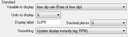
53 12.5 How do I set up the speedometer on my DASH2 PRO? The DASH2 PRO speedometer works by measuring the number of pulses per mile. You will need to calculate and enter this figure to activate the Speedo feature. Measure the distance on the ground that is travelled during one wheel rotation. Assuming that you have an output of one pulse per wheel rotation, one of the following formula should allow you to calculate the number of pulses per mile: Distance in meters: Pulses per km = 1000/rolling circumference of wheel Distance in inches: Pulses per km = 39378/rolling circumference of wheel After setting the number of pulses, click OK and then send the configuration to the DASH2 PRO How do I set an alarm level on the DASH2 PRO? Enter the DASH2 PRO configuration tool. Click on the Alarms icon on the right hand side. Up to five alarms can be set. To set each one select from the drop down list, select whether either an alarm when the condition is above or below the limit is required and set the alarm value. For example, to set an alarm when the inlet air temperature is over 55 degrees C, you would set: 53

54 For more information on alarms and details on the advanced alarms options see here: How do I set up what is displayed on the DASH2 PRO? Each of the three display areas on the five screens of the DASH2 PRO can be set up to display the data from any channel of data available to the DASH2 PRO. These are all set up from the configuration software on the PC, more information can be found here: How do I connect a sensor to the DASH2 PRO? Connect the signal wire from the sensor to one of the four main analogue inputs, connect the sensor ground. If required also connect a 5v or 12v supply to the sensor. Once the wire is physically connected to the DASH2 PRO the input must be set up in the configuration software. Open the DASH2 PRO configuration software and click on the Analogue Inputs tab. 54

55 As configured by default, the input will be read as a voltage and will be stored on the analogue input channel as shown in the table above. For various sensors the scaling can be easily set to convert the voltage reading in to a temperature reading which can easily be displayed in the required units. For example, if there is a water temperature sensor attached to input 1, an oil pressure sensor in analogue 2, and an exhaust thermocouple in analogue three it could be set up like this: Note, when setting up standard sensors, select the channel to map to first, as only certain sensors can be mapped to each channel type. I.E. Temperature sensors to temperature channels. After finishing the configuration send the configuration through the USB port or save to a file to be sent from a data logger. For more details and advanced options on setting up the analogue inputs, see here: Connecting a Wheel Speed Sensor A wheel speed sensor can be connected up to the DASH2 PRO to provide speed and distance information. The wiring for the standard Race Technology wheel speed sensor can be found here: 55
56 When connected to the DASH2 PRO the configuration will need to be set on the PC for using the wheel speed sensor and for setting up the number of pulses per mile. More information on that can be found on the following pages: How do I connect my Fuel Level Sender It is advisable to connect a fuel level sensor directly to the DASH2 PRO rather than via a data logger, this means that the fuel level will be available all of the time even if the data logger is connected. Connect the sensor up as shown in the following page: Fuel level sensors are often 1 wire sensors; follow the instructions on the link for selecting a sensor pull up value. Configure the DASH2 PRO to display the analogue channel on the screen for the fuel level sensor. With the tank empty and the DASH2 PRO operating, note down the voltage recorded by the sensor at each stage as the tank is filled up. After completing this a full table of values of voltage and tank capacity should be available. Something like this: Fuel Voltage In the configuration software for the DASH2 PRO, select the Analogue Inputs box 56


57 and then click on the 'Input Equation' for the correct analogue input. Select the option to enter values from a table and then enter the values for the voltage and fuel level. 57

58 When this channel is displayed it should now show the fuel level How do I configure the RPM on my DASH2 PRO? Start up the DASH2 PRO configuration software. Click on the Wheel speed and RPM icon. 58

59 Set up the number of pulses per engine revolution from the engine speed sensor. The smoothing time for the RPM can also be set here. For a good quality signal it is recommended that the maximum rate of change and the smoothing time are both kept at zero. If the input signal is of very poor quality these settings can be used to filter out any noise on the input. By default the RPM signal is set up to come from the High RPM input. This input connects directly to the low tension side of the ignition coil. If the Low level input is used it can be selected here. If the RPM signal is to come from an ECU interface, CAN input or from another serial source then the internal RPM sensor can be disabled here How do I set up the gear indicator on the DASH2 PRO? The gear indicator on the DASH2 PRO can be set up to calculate gearing from engine and vehicle speed or to read the value from a sensor channel. The sensor can be either connected directly to the DASH2 PRO or the value can be read from the serial or CAN bus. Open the DASH2 PRO configuration software and click on the Setup Gear Indicator icon. Select the method to be used for the data, if the data is to come from a sensor then the values in the table are the upper and lower limits for the sensor readings. For more detailed information on this go 59
60 12.13 How do I connect a 1 or 2 wire sensor to the DASH2 PRO. The DASH2 PRO requires a voltage input on its sensor inputs that goes from a minimum of 0v to 12v maximum. For sensors with 3 wires, typically you have: voltage supply 0v or ground signal out Note that in some cases the ground connection maybe via the body of the sensor in which case there will only be 2 wires coming out of the actual sensor - however this is relatively unusual. In this case the signal out can be connected directly to the one of the analogue inputs on the DASH2 PRO. For sensors with 1 or 2 wires, it is slightly more complicated. For a sensor with 2 wires it is typically a variable resistor with both ends of the resistor available: In this case we need to use a "pull up" resistor to convert the changing resistance to a changing voltage: 1 wire sensors are the same, but in this case the 2nd wire on the sensor is ground and made via the sensor body earthing to the engine casting etc. 60
61 Once the sensor is connected to the DASH2 PRO with the pull up resistor then it can be calibrated in the normal way. For more information on this, please refer to this section Choosing a value for the pull up resistor Please note that it is the installer responsibility to choose the correct value of pull up resistor when using 1 or 2 wire sensors with Race Technology products. For a particular sensor type there is no correct value of resistor however it must be selected to be somewhere near to ensure: There is a reasonable voltage swing, ideally this wants to be a few volts rather than a few milli volts. A small signal can get easily lost in noise. You cannot take too much current from the 5v reference output, depending on the product typically this cannot be more than a total of 100mA. The table below gives a indication of suitable pull up resistor values: Sensor Pull up resistor Notes 100 Ohms or lower (typical for low cost/quality VDO sensors) Between about 100 Ohms to 500 Ohms Between about 500 Ohms to a few kiloohms Between a few kilohms and a few 10 s kilohms 100 Ohms With such a low pull up resistor you will only be able to have a maximum of 2 sensors before you use 100mA Between about 100 Ohms to 500 Ohms 500 Ohms 1 kiloohm (1k) This is the normal setup for Race Technology Supplied sensors 10 kiloohm (10k) 61


62 12.14 Connect and set up a GoPro interface cable There are two wires on the GoPro interface cable, these need to be connected up as shown here: The GoPro must be set up in "1 button mode" so when it turns on it begins recording automatically. After connecting up the cable the configuration software will need to be changed to set the status output up correctly. Using the DASH2 PRO configuration software, select "Output Drivers" and enable GoPro Status on output 4: 62
DASH2 Instruction Manual
 DASH2 Instruction Manual Potenza Sports Cars Limited, 2007 Version 3.2 Introduction Congratulations on your purchase of a DASH2 display unit for Westfield sports cars. This is an advanced, feature-packed
INSTALLING THE DASH3...
 Table of Contents 1 THE DASH3... 4 1.1 LAP TIMING FEATURES... 6 1.2 SOFTWARE SUPPORT... 6 1.3 TECHNICAL SPECIFICATION... 8 1.4 TYPICAL SYSTEM... 9 1.4.1 DL1 or DL2, and DASH3... 9 1.4.2 DL1 or DL2, ECU,
AX22 Performance Computer
 AX22 Performance Computer Built in high accuracy 5Hz GPS Digital accelerometers Compact flash memory Lap beacon input Serial input from ECU/OBDii Very high accuracy measurements of acceleration timings
Features: Contents: If you are missing any of the above components please contact Racepak at
 -------------------------------------------------------------------------------------------- 250-DS-UDX -------------------------------------------------------------------------------------------- Features:
DL1 PRO INTRODUCTION...4
 Table of Contents 1 DL1 PRO INTRODUCTION...4 1.1 WHAT IS THE DL1 PRO?... 4 1.2 WHO IS THE DL1 PRO DESIGNED FOR?... 4 1.3 WHAT DOES THE DL1 PRO DO?... 4 1.4 WHY USE GPS?... 5 1.4.1 Track Mapping... 5 1.4.2
WIRING FOR MXL PRO- 05
 CONSTRUCTIVE DOCUMENTATION 0/0/005 WIRING Notes: general-purpose wiring for MXL PRO 05 CAR/BIKE installation Version.00 WIRING FOR MXL PRO- 05 MXL PRO 05 wiring (CAR/BIKES) Logger pinout: 7 pins Deutsch
Digital Dash I/O Adapter Configuration
 Digital Dash I/O Adapter Configuration The I/O Adapter adds ten inputs/outputs to the 7 digital dash. These inputs and outputs can then be configured as gauges or switches, and data logged locally through
Shift Light Unit Mk2 User Guide V2.1
 Shift Light Unit Mk2 User Guide V2.1 Disclaimer Disclaimer Although every care is taken with the design of this product, JT Innovations Ltd. can in no way be held responsible for any consequential damage
Temperature Programming Quick Reference Guide
 Temperature Programming Quick Reference Guide Normal Mode Dial Brightness (press one at a time) Peak Mode Factory Default Reset (Hold for 5 seconds) High Alert Setting Mode Use LEFT or RIGHT buttons to
TC200 Operation & Installation Guide. Revision 1.0
 TC200 Operation & Installation Guide Revision 1.0 2006 2007 Monit Limited. Product of New Zealand. Introduction Thank you for your purchase of this rally computer product. At monit, we take pride in everything
Table of Contents MOTOROLA SEQUENTIAL MOTOROLA BACKWARD APPENDIX C. PIN CONNECTIONS SERIAL DATA OUT CONNECTOR...
 Table of Contents INTRODUCTION... 3 PARTS SUPPLIED... 3 BEFORE YOU BEGIN... 3 DESCRIPTION OF OPERATION... 4 RT MESSAGE... 4 CAN ID LENGTH... 4 CAN ID... 5 FILTER LOCATION... 5 FILTER VALUE... 5 START BIT...
DL1 CLUB INTRODUCTION...
 Table of Contents 1 DL1 CLUB INTRODUCTION... 4 1.1 WHAT IS THE DL1 CLUB?... 4 1.2 WHO IS THE DL1 CLUB DESIGNED FOR?... 4 1.3 WHAT DOES THE DL1 CLUB DO?... 4 1.4 WHY USE GPS?... 5 1.4.1 Track Mapping...
ADR. - Configuration and Functionality USER MANUAL
 ADR - Configuration and Functionality USER MANUAL Installation Contents Installation... 3 Dimensions... 3 Configuration... 4 Connection to the ADR... 4 Password Support... 5 Device Configuration... 5 Device
SPA DESIGN MICROPROCESSOR SPEEDO MANUAL
 SPA DESIGN MICROPROCESSOR SPEEDO MANUAL SPA DESIGN MICROPROCESSOR SPEEDO INSTALLATION AND OPERATING MANUAL CONTENTS PAGE 2...INSTRUMENT FEATURES. PAGE 3...INSTALLATION DETAILS. PAGE 4...OPERATING INSTRUCTIONS.
CAN DISPLAY DASH & LOGGER SYSTEM QUICK START GUIDE
 CAN DISPLAY DASH & LOGGER SYSTEM QUICK START GUIDE AEM Performance Electronics 2205 126th Street Unit A, Hawthorne, CA 90250 Phone: (310) 484-2322 Fax: (310) 484-0152 http://www.aemelectronics.com Instruction
RaceCapture/Pro 3. Next generation of data, telemetry, and control. Live-streaming to Podium
 RaceCapture/Pro 3 Next generation of data, telemetry, and control Your time on track matters and you want to maximize every minute and dollar toward tuning the engine, honing your racecraft, or finding
Flow Chart Programming Instructions for : Pressure 2 1/16 PROFESSIONAL RACING GAUGE START HERE PROGRAM MAIN MENU
 Flow Chart Programming Instructions for : Pressure 2 1/16 PROFESSIONAL RACING GAUGE START HERE PROGRAM MAIN MENU (Press one button at a time) MAIN MENU PEAK HI ONE AT A TIME DOWN UP - + NORMAL LIGHTING
CH1. Figure 1: M3 LOG Advanced
 TECHNICAL DOCUMENTATION 03/09/2003 GAUGE Notes: M3 LOG Advanced technical documentation, dimensions and pinout. Ver 1.05 M3 LOG Advanced Internal lateral accelerometer CH1 Beacon Speed COM Power CH2 CH3
Programming the R34 MFD
 Programming the R34 MFD Author Ned (with web help from anyone whosepictures or wordsi stole) The MFD Shift light 4way joystick (lit at night) DISP R E T U R N ME NU MODE DISP Display button, takes you
M2500 Engine Controller Configuration Manual
 M2500 Engine Controller Configuration Manual Revision: 08-04-2011 Page 1 Contents 1 Preface... 4 2 Configuration from front panel... 5 2.1 Engine Controller Configuration... 6 2.1.1 RPM settings... 6 2.1.2
CAN bus switch panels mounted either on the dash or the steering wheel allow for vastly simplified wiring and reduced weight.
 POWER MANAGEMENT UNIT PMU-16 PMU-16 Decades ago, the critical electronic components in a race car were the ignition coil and points. Race cars are now sophisticated machines equipped with advanced engine
Podium Data Analysis Software. User Manual. SWIS10 Version
 SWIS10 Version Issue 1.00 March 2003 Contents 1 Introduction 5 1.1 What is Podium? 5 1.2 About This Manual 5 1.3 Typographical Conventions 6 1.4 Getting Technical Support 6 2 Getting Started 7 2.1 System
TECHNICAL DOCUMENTATION 10/10/2005 GAUGE. MyChron 3 LOG BIKE. Introduction. Notes: MyChron 3 LOG BIKE technical documentation Version 1.
 TECHNICAL DOCUMENTATION 10/10/2005 GAUGE Notes: MyChron 3 LOG BIKE technical documentation Version 1.06 MyChron 3 LOG BIKE Figure 1: MyChron 3 LOG BIKE Introduction MyChron 3 LOG BIKE represents the perfect
HP8440 Power Box. The Intelligent Power Distribution Module. Installation and User Guide for PCM Version 9.02
 HP8440 Power Box The Intelligent Power Distribution Module Installation and User Guide for PCM Version 9.02 1 Introduction The Power Control Module is an innovative, intelligent and programmable module
Waterproof. Keypad/Reader/Controller
 Waterproof Keypad/Reader/Controller User Manual W1-C W3-C User manual 1. Packing List Name Quantity Remarks Digital Keypad-W1-C/W3-C 1 User manual 1 Screw driver 1 Rubber bungs 4 6*27mm, used for fixing
WARNING!!!!!!!!! IMPORTANT INFORMATION: READ BEFORE INSTALLATION!
 V_Net Relay Module Installation Instructions: Part Number: 230-VM-RELAY WARNING!!!!!!!!! IMPORTANT INFORMATION: READ BEFORE INSTALLATION! The relay outputs of the 230-VM-RELAY module may turn on when not
Energy Management System. Operation and Installation Manual
 Energy Management System Operation and Installation Manual AA Portable Power Corp 825 S 19 TH Street, Richmond, CA 94804 www.batteryspace.com Table of Contents 1 Introduction 3 2. Packing List 5 3. Specifications
12.3 Pro Dash Quick Start Guide
 12.3 Pro Dash Quick Start Guide 553-111 CONTENTS: Package Contents... 3 Mounting... 3 Connections... 4 Main Connector... 4 CAN Extension Harness... 6 USB... 7 GPS Antenna... 7 Cleaning... 7 Touchscreen
USER MANUAL. V1.0.2, Rev A
 1 USER MANUAL V1.0.2, Rev A 2 Contenido PRODUCT OVERVIEW... 5 1. INSTALLATION... 6 1.1 Selecting a Mounting Location... 6 2. MOUNTING THE ALBACOMBI UNIT... 7 2.1 DIN Rail Mounting... 7 2.2 Connecting to
Haltech IQ3 Street Dash Guide
 Haltech IQ3 Street Dash Guide Thank you for purchasing a Haltech IQ3 Street dash. This guide provides information on the installation and basic use of your dash. Your dash is preconfigured by Haltech with
explona dakar 2007 User manual
 explona EXPLONA explona dakar 2007 User manual explona dakar 2007 is an intuitive to use advanced tripmeter. It conforms to the Dakar 2007 technical regulations. The regulations are available on the organizer's
NG7 User Manual Polaris 16/05/2017 3:40 pm Page 1 NG7. User Manual
 NG7 User Manual Polaris 16/05/2017 3:40 pm Page 1 NG7 User Manual NG7 User Manual Polaris 16/05/2017 3:40 pm Page 2 Thank you for purchasing the Polaris NG7. Before operation, be sure to thoroughly read
Options. Parts List. Optional Expansion Hub Optional Ignition Module Optional Memory Card
 Options Optional Expansion Hub Optional Ignition Module Optional Memory Card View boost, speed, and gear on the LCD Display. View the ignition changes on the LCD Display. Log and store map data. Card storage
PduSetup User Manual. Professional Electronics for Automotive and Motorsport
 Professional Electronics for Automotive and Motorsport 6 Repton Close Basildon Essex SS13 1LE United Kingdom +44 (0) 1268 904124 info@liferacing.com www.liferacing.com PduSetup User Manual Document revision:
REX F-0-9 Standalone or Access Controller
 REX F-0-9 Standalone or Access Controller Power supply The controller need s external power supply to operate. The Spider W40 power supply is sufficient to power two controllers and two 12V electric strikes
EVO Dear EVO3 Pista/Pro Owner,
 User Manual EVO3 1.00 Dear EVO3 Pista/Pro Owner, Your EVO3 belongs to the latest generation of AIM loggers for car / bike racing and provides you with a powerful, compact, reliable and expandable data
Digital Speed Controller User Manual
 Diesel Engine for Generators Digital Speed Controller User Manual (DSC-1000) Ver_1.0 Doosan Infracore 페이지 1 / 36 Contents 1. Product Overview and General Specification 1.1 Product Information 1.2 Product
CHAPTER 3B: ELECTRONIC POWER STEERING
 Electronic Power Steering CHAPTER 3B: ELECTRONIC POWER STEERING NOTE: The basic steering system, such as the tie rod ends, drag links axles, etc., is covered in Chapter 3A: Steering. In 2012, Cub Cadet
705 INSTALLATION MANUAL
 705 INSTALLATION MANUAL 2 Table of Contents Features...03 Specifications...04 Quick - Start...05 Remote Control...07 Hardware Installation...10 705 Models Additional Info...14 Owner s Record...15 3 Features
The GF-2 is able to measure G-forces even if the instrument is not mounted exactly on the vertical axis of the aircraft.
 GF-2 +-10g Tilt Compensated dual range aviation G-force meter Operating Manual English 1.00 Introduction The GF-2 is a 3 1/8 G-force meter capable of measuring G-forces exerted in an aircraft up to +-10g.
Standalone Keypad Access Control. User Manual. Please read the manual carefully before use this unit
 Standalone Keypad Access Control User Manual Please read the manual carefully before use this unit 1. Packing List Name Quantity Remarks Keypad 1 User manual 1 Screw driver 1 Φ20mm 60mm,Special for keypad
Standalone Keypad Access Control. User Manual. SS-TS2000 Size:120*80*25 mm
 Standalone Keypad Access Control User Manual SS-TS2000 Size:120*80*25 mm Please read the manual carefully before use this unit 1. Packing List Name Quantity Remarks Keypad 1 User manual 1 Screw driver
INSTALLATION INSTRUCTIONS 5" SINGLE CHANNEL ULTIMATE TACH
 Instr. No. 2650-887C INSTALLATION INSTRUCTIONS 5" SINGLE CHANNEL ULTIMATE TACH MODEL 6871, 6872, 6873, 6874, 6875, 6877 IMPORTANT WEAR SAFETY GLASSES 5 4 6 COPYRIGHT PATENT PENDING 3 7 8 PLAYBACK 9 2 0
MXL PRO 05 PLUG & PLAY KIT FOR SUZUKI GSX R YOSHIMURA RACING HARNESS cc
 INSTALLATION DOCUMENTATION 18/11/2005 P&P KIT Installation Manual: MXL PRO 05 P&P kit for SUZUKI GSX R Yoshimura Racing Harness 2004 2005 1000 cc Version 1.00 Suzuki GSX-R Yoshimura Racing Harness 1000cc
PowerView Model PV750. Installation and Operations Manual Section 78
 PowerView Model PV750 Installation and Operations Manual 00-02-0686 08-20-10 Section 78 In order to consistently bring you the highest quality, full featured products, we reserve the right to change our
ebox Gold/Extreme for MyChron4 User Manual
 for MyChron4 This user manual is copyright of Aim srl. All procedures here explained can change also substantially. Please check website to get the most recent ones. Aim reserves the right of periodically
C Combined Display Logger USER MANUAL
 C185 - Combined Display Logger USER MANUAL MoTeC C185 User Manual Copyright 2015 MoTeC Pty Ltd The information in this document is subject to change without notice. While every effort is taken to ensure
RaceCapture/Apex. Ruggedized, powerful motorsports telemetry
 RaceCapture/Apex Ruggedized, powerful motorsports telemetry RaceCapture/Apex is a powerful motorsports telemetry system designed for harsh environments. Whether you need telemetry for your open-cockpit
Installation Guide. Version: 5.6 (Digitax) April 2016
 April 2016") Installation Guide Version: 5.6 (Digitax) April 2016 STEP SUMMARY PAGE 1 Fit Mounting Bracket and Antenna 5 2 Connect Loom to Vehicle 6 3 Connect Screen to Loom 8 4 Configure SmartMove 9 5 Test SmartMove
Installation Guide Version: 5.6 (Digitax) April 2016 STEP SUMMARY PAGE 1 Fit Mounting Bracket and Antenna 5 2 Connect Loom to Vehicle 6 3 Connect Screen to Loom 8 4 Configure SmartMove 9 5 Test SmartMove
VR2 R-NET LED R-NET LCD. Controller System Operation
 VR2 R-NET LED R-NET LCD Controller System Operation 1.VR2 Controller Operation 1.1 Controls/JSM 1.2 Button/Indicator 1.3 Control System Status indication 1.4 Module Wiring 1.5 VR2 Locking / Unlocking The
DirectCommand Installation 5 Channel Spreader Control Module Technology
 DirectCommand Installation Ag Leader Technology Note: Indented items indicate parts included in an assembly listed above Part Name/Description Part Number Quantity Direct Command Kit 4100582 1 Cable Installation
OLED INSTRUCTION MANUAL (VBDSP04, VBDSP05 F, and VBDSP05 L)
") OLED INSTRUCTION MANUAL (VBDSP04, VBDSP05 F, and VBDSP05 L) Contents Introduction... 5 Key Features... 5 Parts supplied with RLVBDSP04/05... 6 Optional Accessories... 6 OLED Setup... 7 Video VBOX/ Video
OLED INSTRUCTION MANUAL (VBDSP04, VBDSP05 F, and VBDSP05 L) Contents Introduction... 5 Key Features... 5 Parts supplied with RLVBDSP04/05... 6 Optional Accessories... 6 OLED Setup... 7 Video VBOX/ Video
5450 NW 33rd Ave, Suite 104 Fort Lauderdale, FL Fruitland Ave Los Angeles, CA UM Channel Monitor.
 5450 NW 33rd Ave, Suite 104 Fort Lauderdale, FL 33309 3211 Fruitland Ave Los Angeles, CA 90058 UM-600 6-Channel Monitor Version 2 Installation and Operation Manual Rev. G P/N145F-12990 PCO 00007462 (c)
W3-M. Metal waterproof standalone access control/reader. User Manual
 W3M Metal waterproof standalone access control/reader User Manual Name Digital Keypad W3M User Manual Screw driver Rubber bungs Selftapping screws Diode 1. Packing List Quantity 1 1 1 4 4 1 Remark 6*27mm,
F6-Fingerprint. Access Control/Reader. User Manual. F6 - Simplified Instruction. (Master Code) # (Factory default:1234) Enter the Programming Mode
 # (Factory default:1234) Enter the Programming Mode") -Fingerprint Access Control/Reader Function Description Enter the Programming Mode - Simplified Instruction Operation (Factory default:1234) Change the Master Code Add Fingerprint User Add Card User Add
-Fingerprint Access Control/Reader Function Description Enter the Programming Mode - Simplified Instruction Operation (Factory default:1234) Change the Master Code Add Fingerprint User Add Card User Add
MDVR 800 QUICK START GUIDE
 MDVR 800 QUICK START GUIDE Introduction & Warnings Before installing please read the following warnings carefully. Stortech CCTV strongly recommends that all connections and installations are carried out
/8H Infinity Hardware Specification STOP! THIS PRODUCT HAS LEGAL RESTRICTIONS. READ THIS BEFORE INSTALLING/USING!
 Instruction Manual 30-7106/8H Infinity Hardware Specification STOP! THIS PRODUCT HAS LEGAL RESTRICTIONS. READ THIS BEFORE INSTALLING/USING! THIS PRODUCT MAY BE USED SOLELY ON VEHICLES USED IN SANCTIONED
PCS D200 DASH LOGGER USER GUIDE v2.0
 PCS D200 DASH LOGGER USER GUIDE v2.0 Ph: 1.804.227.3023 www.powertraincontrolsolutions.com Powertrain Control Solutions PCS D200 Dash Logger User Guide 1 Introduction The D200 Dash Logger is a powerful
Installation & Calibration Manual
 Installation & Calibration Manual UT SkidWeigh Plus Series Lift Truck Onboard Check Weighing System With Monitoring Of All Operational Idling Times Automatic Idling Times Notification Within Specific Utilization
Single Door Standalone Access Control User Manual
 Single Door Standalone Access Control User Manual Reading this manual carefully before install and use the device 1. Packing List Name Quantity Remarks Keypad User manual Screw driver Rubber plug Self
GEN 6 LOCKPICK INSTALLATION OPTIONS COPYRIGHT 2010 COASTAL ELECTRONIC TECHNOLOGIES, INC.
 AFTERMARKET FRONT/BABY CAMERA VIDEO CONNECT HERE FRONT/BABY CAM POWER TO LOCKPICK RED W/BLACK STRIPE WIRE TO LOCKPICK BLACK GROUND WIRE UNPLUG ORIGINAL RADIO CONNECTORS THEN PLUG IN HERE PLUG AND PLAY
Installation Instructions
 Alliance Arming Station AL-1111, AL-1116 1048520C September 2006 Copyright 2006, GE Security Inc. Introduction This is the GE Alliance Arming Station for models AL-1111 (four-line LCD) and AL-1116 (four-line
BEP 600-ACSM AC SYSTEMS MONITOR. Installation and Operating Instructions. Page 1
 BEP 600-ACSM AC SYSTEMS MONITOR Installation and Operating Instructions Page 1 This page has been deliberately left blank Page 2 Table of Contents 1. BASICS 4 WARNING AND CAUTION 4 WARNING 4 CAUTION 4
DATA ACQUISITION KIT DESCRIPTION INSTALLATION LAYOUT. Wirings connections
 DATA ACQUISITION KIT DESCRIPTION EVO 3 data logger (8 or 13 channels version) Interface Junction Box Aim Infrared transmitter 12 Volts power cable for infrared transmitter Infrared receiver Wirings to
e-ask electronic Access Security Keyless-entry OEM / Dealer / Installer Cargo Lock / Unlock Version Installation & Instructions (UM04 ~ )
") e-ask electronic Access Security Keyless-entry OEM / Dealer / Installer Cargo Lock / Unlock Version Installation & Instructions (UM04 ~ 18990-04) Table of Contents Introduction... 1 e-fob Operation and
e-ask electronic Access Security Keyless-entry OEM / Dealer / Installer Cargo Lock / Unlock Version Installation & Instructions (UM04 ~ 18990-04) Table of Contents Introduction... 1 e-fob Operation and
SDL User s Manual. Contents. Introduction... 1 Overview Installation Sport Dash Manager Software... 23
 MoTeC SDL User s Manual Contents Introduction... 1 Overview... 2 Display...2 Alarms...5 Data Logging...5 Other Functions...7 Measurement Inputs...8 Auxiliary Outputs...12 Communications Overview...13 ECU
CV-110SPK Standalone Keypad/Prox Access Control Installation Instructions
 CV-110SPK Standalone Keypad/Prox Access Control Installation Instructions 1. Packing List Qty Name Remarks 1 1 1 2 2 1 Keypad User manual Screwdriver Wall plugs Self-tapping screws Torx screw 0.8 x 2.4
R-DAS Tiny User s Manual
 R-DAS Tiny User s Manual Scope This document is an addendum to the R-DAS manual and is specific to the R-DAS Tiny (hardware V4.x). For general concepts about the R-DAS, please see the R-DAS Manual. New
GF-1. Introduction. 1 Features. +-10G Tilt Compensated dual range aviation G-force meter. Operating Manual English 1.00
 GF-1 +-10G Tilt Compensated dual range aviation G-force meter Operating Manual English 1.00 Introduction The GF-1 is a 2.25 G-force meter capable of measuring G-forces exerted in an aircraft up to +-10G.
5450 NW 33rd Ave, Suite 104 Fort Lauderdale, FL Fruitland Ave Los Angeles, CA SST7000 SST7100. Speed Switch / Transmitter
 5450 NW 33rd Ave, Suite 104 Fort Lauderdale, FL 33309 3211 Fruitland Ave Los Angeles, CA 90058 SST7000 SST7100 Speed Switch / Transmitter Installation and Operation Manual Rev. C P/N145F-13112 PCO 00009270
B&W RearView Camera Installation & Operation
 B&W RearView Camera Installation & Operation CA52 (Camera) FOR MORE INFORMATION WWW.STRATEGICVISTA.COM BEFORE OPERATING THIS SYSTEM, PLEASE READ THIS MANUAL THOROUGHLY AND RETAIN IT FOR FUTURE REFERENCE
Display Unit User Manual
 Display Unit User Manual Contents 3 Specifications 3 Display Specifications 3 Absolute Maximum Ratings 3 Characteristics 4 Get started 4 Wiring 5 Application interface 5 Firmware upgrade 8 Settings 9 Display
VBOX II 20Hz GPS Data Logger. User Guide
 VBOX II 20Hz GPS Data Logger User Guide Page 1 of 23 VBOX II OVERVIEW... 3 INTRODUCTION... 4 FEATURES... 4 STANDARD INVENTORY... 5 OPTIONAL ACCESSORIES... 5 OPERATION... 6 GETTING STARTED... 12 VBOX II.VBO
Installation Guide. Version: 6.1 (Digitax 4G) July 2018
 July 2018") Installation Guide Version: 6.1 (Digitax 4G) July 2018 STEP SUMMARY PAGE 1 Fit Mounting Bracket and Antenna 5 2 Connect Primary Loom to Vehicle 5 3 Connect Secondary Loom to Vehicle 8 4 Connect Screen
Installation Guide Version: 6.1 (Digitax 4G) July 2018 STEP SUMMARY PAGE 1 Fit Mounting Bracket and Antenna 5 2 Connect Primary Loom to Vehicle 5 3 Connect Secondary Loom to Vehicle 8 4 Connect Screen
CYGNUS MR 500 TAXIMETER USER MANUAL ISSUE 3
 CYGNUS MR 500 TAXIMETER USER MANUAL ISSUE 3 Cygnus MR500 Taximeter User Manual Visit Cygnus Online at: www.cygnus-automotive.com ii Contents 2009 Cygnus Automotive Limited 1 ABOUT THIS MANUAL 1 2 THE MR500
!"#$%&'()&'*+#,,-$#*+&(.,./0&)-12,%3
&'*+#,,-$#*+&(.,./0&)-12,%3") !"#$%&'()&'*+#,,-$#*+&(.,./0&)-12,%3 Cosworth's Omega ICD is a widescreen TFT colour display coupled with a fully featured data logger in a single attractive aluminium housing. Using a widescreen 6.2"
!"#$%&'()&'*+#,,-$#*+&(.,./0&)-12,%3 Cosworth's Omega ICD is a widescreen TFT colour display coupled with a fully featured data logger in a single attractive aluminium housing. Using a widescreen 6.2"
TECHNICAL DATASHEET #TDAX050000K CAN
 This cost-effective, compact and robust CAN display shows machine, engine and transmission operating parameters and service codes. Enhanced operating information made available to a vehicle operator improves
UCIT LIVE HD 4 Camera DVR. Installation Manual. 1/18 Version 1.0
 UCIT LIVE HD 4 Camera DVR Installation Manual 1/18 Version 1.0 This is a step by step guide that will walk you through installing the UCIT LIVE HD 4 Channel Camera System. Basic wiring experience and knowledge
Panel Indicators. NEW 4~20mA Panel Display. Process Indicators INTECH INSTRUMENTS.
 The LPI-LCD-6-4~20mA panel display is ideal for displaying a variety of process variables, and is easy to scale to your required engineering units. LPI-LCD-6 4~20mA Panel Display. Loop powered. Loop powered
intelligent monitoring solutions C A N t r a k C O N F I G U R A B L E I N P U T M O D U L E ( C C I M ) I N S T A L L A T I O N M A N U A L
 I N S T A L L A T I O N M A N U A L") intelligent monitoring solutions C A N t r a k C O N F I G U R A B L E I N P U T M O D U L E ( C C I M ) I N S T A L L A T I O N M A N U A L CCIM CANtrak Configurable Input Module Before you start - what
intelligent monitoring solutions C A N t r a k C O N F I G U R A B L E I N P U T M O D U L E ( C C I M ) I N S T A L L A T I O N M A N U A L CCIM CANtrak Configurable Input Module Before you start - what
Electrical Data. Ethernet. LIN Bus. Internal Sensors. Part Number
 Cosworth's Omega ICD is a widescreen TFT colour display coupled with a fully featured data logger in a single attractive aluminium housing. Using a widescreen 6.2" TFT, coupled with dedicated graphic processors,
1020 / 1022 INSTALLATION MANUAL
 1020 / 1022 INSTALLATION MANUAL 2 Table of Contents Features...03 Specifications...04 Quick - Start...05 Remote Control...07 Hardware Installation...10 1020TSV, 1022TSV, 1020YV, 1022YV, 1020TSH, 1022TSH
ECI1. COMPASS display. ECI1-REV For latest update: Electronic Compass Indicator ECS1
 ECI1 COMPASS display Electronic Compass Indicator ECS1 ECI1-REV. 1.3 20-12-2004 For latest update: www.elproma.com/compass Contents 1 Introduction... 1 1.1 Package contents... 1 2 Working... 2 2.1 The
PRODUCT USER MANUAL 12V. 5 Mirror + REVERSE camera IP67 PAGE 1 GX53HDM ABC-123. Mount INSTRUCTION MANUAL. Guide Lines
 PRODUCT USER MANUAL 5 Mirror + REVERSE camera 5 12V 120 IP67 ABC-123 Screen Size Clip-On Mount Voltage Wired Wide Angle PAGE 1 Parking IP67 Rating Number Plate Guide Lines Mount INTRODUCTION WELCOME Thank
AiM Infotech. Hondata KPro4. Release 1.01
 AiM Infotech Hondata KPro4 Release 1.01 1 Supported model This tutorial explains how to connect Hondata ECU to AiM devices. Supported model is: Hondata K-Pro4 to AiM devices. 2 Software setup The ECU comes
What s in the Box? REAR VIEW SAFETY
 TM 1 What s in the Box? 1 Full HD Color Infra-red Weather Proof Camera 1 Full HD 7" TFT LCD Color Monitor w/monitor Mount 1 Power Harness 1 66 Camera Cable 1 Power Connection Wire 1 Screw Kit for installation
The PM1000 series is a universal 4 digit LED plug-on display for transmitters with 4-20mA 2 wire output and fitted with DIN43650 connector.
 PM1000 SERIES PLUG-ON DISPLAY BRIGHT LED DISPLAY INDICATION RANGE -999 TO +9999 FITS TO DIN 43650 CONNECTOR PLUG-ON TO ANY TRANSMITTER WITH 4-20MA OUTPUT EASY TO SCALE ON SITE ROBUST DESIGN SET POINT OPTION
5 B&W Rear View System Camera
 5 B&W Rear View System Camera Instruction Manual MODEL: CA453 www.lorexcctv.com Copyright 2007 LOREX Technology Inc. Thank you for purchasing the Lorex 5 Black & White Rear View System Camera. This system
UCIT LIVE 4 Channel Installation Manual
 UCIT LIVE 4 Channel Installation Manual 06/15 Version 2.0 This is a step by step guide that will walk you through installing the UCIT LIVE 4 Channel Camera System. Basic wiring experience and knowledge
Racepak. Ultra Dash. Installation and Operation Instructions 300-DS-UDX6S
 Racepak Ultra Dash Installation and Operation Instructions 300-DS-UDX6S Table of Contents Table of Contents Introduction...1 Six Button Dash Features...1 Package Contents...1 Optional Items:...1 Ultra
OPERATING INSTRUCTIONS 7 SERIES STATIC GENERATORS
 OPERATING INSTRUCTIONS 7 SERIES STATIC GENERATORS GB Contents Page 1 Introduction 4 2 Safety 5 3 Use 6 4 Checking on Delivered Equipment 6 5 General Specification and Dimensions 7 6 Positioning 10 7 Operating
UCIT LIVE HD 4 Camera DVR. Installation Manual. 10/17 Version 2.0
 UCIT LIVE HD 4 Camera DVR Installation Manual 10/17 Version 2.0 This is a step by step guide that will walk you through installing the UCIT LIVE HD 4 Channel Camera System. Basic wiring experience and
Scanner 2000 microefm QuickStart. Installing the Scanner Remote Mount. Direct Mount NUFLO. Part No , Rev. A
 NUFLO Part No. 30165024, Rev. A Scanner 2000 microefm QuickStart Installing the Scanner 2000 H L H L Flow Direct Mount To install the Scanner 2000 microefm using a direct mount to an orifice or cone meter
The Power Systems Industry Experts. Installation Instructions. PT400 Stationary Generator Monitoring System
 The Power Systems Industry Experts Installation Instructions PT400 Stationary Generator Monitoring System PLEASE READ ALL INSTRUCTIONS PRIOR TO INSTALLATION Planning the Installation The monitoring unit
W3-H Waterproof Keypad/Reader/Controller
 W3-H Waterproof Keypad/Reader/Controller User Manual 1. Packing list Name Quantity Digital Keypad W3-H 1 User Manual 1 Screw Driver Rubber Bungs Self Tapping Screws Diode 1 4 4 1 Manager Card 2 Remark
ISSPRO 3 3/8" DIAMETER PROGRAMMABLE SPEEDOMETER Air Core Version
 GENERAL INFORMATION: Operating Voltage: Input: Magnetic sensor or AC generator Transient Protection: +100 V, -400 V Reverse Voltage Protected ISSPRO 3 3/8" DIAMETER PROGRAMMABLE SPEEDOMETER Air Core Version
EnCell Battery Cell Monitor
 EnCell Battery Cell Monitor Instruction Manual Model RCM15S12 NERC Compliant YO R U H T PA TO Z O R E W O D N M I T E enchargepowersystems.com sales@enchargepowersystems.com (888) 407.5040 Contents 1 Warnings,
Instructions for Installing the ShopBot 3- Button Pendant Retrofit for PRT/PRSalphas
 Installing the 3-Button Pendant Retrofit Page -1- Instructions for Installing the ShopBot 3- Button Pendant Retrofit for PRT/PRSalphas The 3-Button Pendant can be added to PRS/PRT alpha ShopBots and can
NxtG-V Install Manual
 NxtG-V Install Manual 1. Product Overview 1.1. Check Parts List Before starting, check whether all the following items have been included with your NxtG-V. If anything is missing, please contact your supplier.
GENERAL DESCRIPTION... 1 INSTALLATION... 2 CONNECTIONS... 3 OVERVIEW... 6 AREA & SPEED METER SETUP (WIZARD)... 9
... 9") TABLE OF CONTENTS For Serial Numbers 30007000-7999 GENERAL DESCRIPTION... 1 INSTALLATION... 2 CONNECTIONS... 3 OVERVIEW... 6 AREA & SPEED METER SETUP (WIZARD)... 9 AREA & SPEED METER USING GPS SETUP (WIZARD)...
TABLE OF CONTENTS For Serial Numbers 30007000-7999 GENERAL DESCRIPTION... 1 INSTALLATION... 2 CONNECTIONS... 3 OVERVIEW... 6 AREA & SPEED METER SETUP (WIZARD)... 9 AREA & SPEED METER USING GPS SETUP (WIZARD)...