Setting big things into motion. Industrial Controllers Catalog 2015
|
|
|
- Chester James
- 6 years ago
- Views:
Transcription

1 Setting big things into motion. Industrial Controllers Catalog 205

2 Product range Tool for Designers, Engineers and Purchasing Agents Your tool for finding industrial controllers for cranes, electro-hydraulic systems, floor conveyors, industrial applications, ships, rail vehicles, and construction machinery of any kind, joysticks and masterswitches with electronic interface adjustment for all machines matching our product portfolio. Take advantage of our fold-out order tool on this page and the detailed tables of contents at the beginning of each position. Multi-axis controller Double-handle controller Single-axis controller Control switch Standard contact-arrangement Technical data Potentiometer HG OEC 2 OEC 4 Electronic control unit MATRIX grip Hall-push button Palm grip Housing Crane control unit Driver seat Ordering information Portable control unit Control pedestal for offshore Naval cruise controller Pedal-controller Gear limit switch DC-contact Signal-cam controller As of
3 Product Portfolio Gessmann is an international market leader. Our success in the market is based upon our decisive focus on innovative product development and the highest possible standards when it comes to quality. Our product range includes: Multi-axis controller, double-handle controller, control switch (master-switch), gear limit switch for hoisting, electro-hydraulic application, material-handling technology and remote control Geared limit switch for joisting equipment Complete crane control unit, portable control unit, pendant control unit, including wiring for all types of cranes, vehicles and industrial applications Operating panels for construction machinery, industrial applications, vehicles and harvesting machines Control pedestals, ship-operating transmitters, sensor units and actual-value transmitters for ship drives Pedal controllers for welding machines, road and rail vehicles Master controllers, panels and control stations for rail vehicles Displays for forklifts and construction machinery Proportional control electronics for solenoid valves Interface electronics with digital and analog outputs matching our controllers Interface electronics with Profibus interface or CAN-bus interface matching our controllers (input/output cards) DC controllers, selector switches (signal controllers) for high-voltage systems Customized solutions for operating devices and electronic units for any type of machinery and vehicles Management certification:

4 Contents Multi-axis controller V6 / VV6 S. -5 V S. 6-9 V8 / VV8 S. 0-3 V85 / VV85 S V24 S V25 S V4 S V20 S V22 S V23 S V2 S Double-handle controller D64 / DD64 S D8 S D85 S D3 S Single-axis controller S S S S S4 S S2 / SS 2 / S2 S S22 / SS22 S S23 S S26 S S27 S S3 S S9 S Control switch N6 S N9 S Standard contact-arrangement S Technical data S Potentiometer S. 0 HG S. -2 OEC 2 S. 3-5 OEC 4 S. 6 Electronic control unit S. 7-8 MATRIX grip S. 9 Hall-push button S Palm grip B S B2 S B3 S B5 S B6 S B7 / B8 S B9 S B0 S B4 / B5 S B20 S B22 S B23 S B24 S B25 S B28 S B29 S Housing S Crane control unit KST 4 S KST 5 S KST 6 S KST 7 / KST 75 S KST 8 S KST 85 S KST 0 S KST 9 S Driver seat KFS 2 S KFS 4 S KFS 82 S KFS 9 S KFS 0 S KFS S KFS 2 S Ordering information S Portable control unit TS S TS 2 S Control pedestal for offshore U 22/32 S U 23/23 S Naval cruise controller AZ S Pedal-controller P7 / PP7 S P8 / PP8 S P0 / P / P2 S Gear limit switch GE /2 S DC-contact SO / SS S Signal-cam controller NU S
5 General Terms and Conditions For our general conditions for sale and delivery please refer to our website at Please also note: Our catalog prices do not include value added tax, which is added separately. The prices are ex-works in Leingarten excluding packaging. Packaging is charged at cost and cannot be returned. For orders below EURO our gross prices are applicable. The minimum invoice amount is EURO 80.00, regardless of the value of the delivered goods. Therefore, we recommend combining small orders. We are entitled to pass on any additional handling and production costs resulting from modifications to the order caused or requested by the customer (both technical modifications and non-compliance with deadlines). Our periods of payment are: 30 days without a discount. These conditions of payment shall be deemed agreed and accepted upon receipt of our written confirmation of orders. All delivered goods shall remain our sole and absolute property until full payment is received. The delivery period only commences upon clarification of all technical details. Unforeseen circumstances justify an appropriate extension of the delivery period. All documents, such as drawings, dimensional drawings, circuit diagrams, etc., are non-binding. We reserve the right to make any changes necessary, in particular changes which serve the technical advancement. The exclusive place of jurisdiction is Heilbronn, Germany.! Warning Certain parts of this electrical device carry hazardous voltages when in operation. Installation, maintenance, modification or retrofitting may only be carried out by qualified personnel in consideration of the appropriate safety precautions. Non-compliance may result in death, severe injuries or substantial property damage. W. Gessmann GmbH P/O Box Leingarten GERMANY Eppinger Straße Leingarten GERMANY Phone +49 (0) Fax +49 (0) gessmann@gessmann.com Bank details Deutsche Bank Heilbronn (BLZ ) account-no.: SWIFT-Code: DEUT DE SS 620 IBAN-Code: DE Kreissparkasse Heilbronn (BLZ ) account-no.: 4776 SWIFT-Code: HE IS DE 66 IBAN-Code: DE Landesbank Baden-Württemberg (BLZ ) account-no.: SWIFT-Code: SOLA DE ST IBAN-Code: DE Tax No.: 65205/7440 Finanzamt Heilbronn Sale tax ID No.: DE Commercial Register Stuttgart HRB 0032 Managing Director: Alwin Ehrensperger
6 Multi-axis controller V6 / VV6 The multi-axis controller V6 / VV6 is available in either single-axis or multi-axis options and is a robust controller used commonly in electro-hydraulic applications. The modular design and many possibilities of combination with our handles enables the switching device to be used universally. The V6 / VV6 is resistant to oil, maritime conditions e.g. offshore / vessels, UV radiation typically from the sun. Technical data Mechanical life V6 Mechanical life VV6 Operation temperature Degree of protection 0 million operating cycles 20 million operating cycles -40 C til +60 C IP 54 front Example V62L S5 P T - 0 Z P + 03A R C - A05 P34 + A0 C0 - X Basic unit V62L 2-axis left Control-handle extended S5-20 mm Gate P Cross gate Grip / palm grip T Dead man Axis (direction -2) 0 2 Contacts (2A 250V AC5) Z P Spring return Potentiometer Axis 2 (direction 3-4) 03A R C 6 Contacts (4A 250V AC5) Friction brake Opto-electronical encoder Describtion axis (direction -2) A05 Arrangement MS 2 P34 Potentiometer T396 2x5 kohm Describtion axis 2 (direction 3-4) A0 Arrangement MS 24-0 C0 OEC 2-- Special model X Special / customer-specific page
7 Multi-axis controller V6 / VV6 Combination possibilities with our ball handles B B3 B5 B6 B0 B4 B5 B22 B24 B28 S. 28 S. 32 S. 35 S. 37 S. 43 S. 45 S. 49 S. 53 S. 57 Basic unit V62L S5 P T - 0 Z P + 03A R C - A05 P34 + A0 C0 - X V6L -axis left Identification of the installation variants V6R -axis right with switching directions: V6. -axis V64. -axis 5 V62L V62R 2-axis left 2-axis right V64 VV6L 2-axis reinforced version -axis left 2 V6L/VV6L 6 V6R/VV6R VV6R -axis right VV6. -axis VV64. -axis VV62L 2-axis left VV62R 2-axis right VV64 2 axis Control-handle extended* V62L/VV62L V62R/VV62R 5-6 Standard 80 mm S3-40 mm S5-20 mm S8 +20 mm *Only available in combination with handle! Gate P Cross gate 2 V64./VV V6./VV6. P X Special gate Grip / palm grip Knob (standard) 3 4 M MN T MT* H MH D MD* DV MDV* Mechanical zero interlock Mechanical zero interlock (push down) Dead man Mechanical zero interlock + dead man Signal button Mechanical zero interlock + signal button Push button Mechanical zero interlock + push button Flush push button Mechanical zero interlock + flush push button V64/VV64 *Only possible with VV6! B... Palm grip B... (see Palm grip page 28) Attention! When using some handles reduces the deflection angle to 28 degrees! V205/ page 2
8 Multi-axis controller V6 / VV6 V62L S5 P T - 0 Z P + 03A R C - A05 P34 + A0 C0 - X Axis : direction -2 left / direction 5-6 right (Standard contacts gold-plated 2A 250V AC5) 0 2 contacts Standard contact - arrangement see page contacts z.b contacts A980 MS contacts A05 MS contacts A0500 MS contacts A0 MS 24-0 A = silver contacts (4A 250V AC5) A99 contact - arrangement according customer request Z R (P) Spring return Friction brake Possibility of mounting potentiometer and encoder (Gessmann-types) P Potentiometer P3 T396 2x0,5 kohm l max. ma P32 T396 2x kohm l max. ma P33 T396 2x2 kohm l max. ma P34 T396 2x5 kohm l max. ma P35 T396 2x0 kohm l max. ma More potentiometer on request! C Encoder C... Encoder see page 8 If both axis identical, it`s enough to describe one axis! Beispiel A05P34 + A05P34 => A05P34 V62L S5 P T - 0 Z P + 03A R C - A05 P34 + A0 C0 - X Axis 2: Direction 3-4 left / Direction 7-8 right (not applicable to V/VV6, V/VV6., V/VV64.) (Standard contacts gold-plated 2A 250V AC5) 0 2 contacts Standard contact - arrangement see page contacts z.b contacts A980 MS contacts A05 MS contacts A0500 MS contacts A0 MS 24-0 A = Silver contacts (4A 250V AC5) A99 contact - arrangement according customer request Z R (P) Spring return Friction brake Possibility of mounting potentiometer and encoder (Gessmann-types) P Potentiometer P3 T396 2x0,5 kohm l max. ma P32 T396 2x kohm l max. ma P33 T396 2x2 kohm l max. ma P34 T396 2x5 kohm l max. ma P35 T396 2x0 kohm l max. ma More potentiometer on request! C Encoder C... Encoder see page 8 page 3
9 Multi-axis controller V6 / VV6 V62L S5 P T - 0 Z P + 03A R C - A05 P34 + A0 C0 - X Special model X Special / customer-specific Special model Indicating labels Indicating labels with engraving V205/ page 4
10 Multi-axis controller V6 / VV6 T = Dead man's button H = Signal button M = Latch for mechanical zero interlock T H MN M MP Knob solid D= Push button 42 Palm grip B max. 4 Cover plate IP 54 IP Palm grip B B T= Dead man's button A 25 B CAGE CLAMP connection max. 2,5mm² B Palm grip B5 Potentiometer T OEC-mounting Hole pattern ,5 72 Type No. of contacts Dim. A Dim. B , page 5
11 Multi-axis controller V The multi-axis controller V is a robust switching device for crane and hoisting applications. The modular design enables the switching device to be used universally. The V is resistant to oil, maritime conditions e.g. offshore / vessels, UV radiation typically from the sun. Technical data Mechanical life Operation temperature Degree of protection 0 million operating cycles -40 C til +60 C IP 54 front Example VL S5 P T - 0 Z P + 03A R - A05 P324 + A0 - X Basic unit VL 2-axis left Control-handle extended S5-20 mm Gate P Cross gate Grip / palm grip T Dead man Axis (direction -2) 0 2 Contacts (2A 250V AC5) Z P Spring return Potentiometer Axis 2 (direction 3-4) 03A R 6 Contacts (4A 250V AC5) Friction brake Describtion axis (direction -2) A05 Arrangement MS 2 P324 Potentiometer T365 2x5 kohm Describtion axis 2 (direction 3-4) A0 Arrangement MS 24-0 Special model X Special / customer-specific V205/ page 6
12 Multi-axis controller V Combination possibilities with our ball handles B B5 B6 B0 B4 B5 B22 B24 B28 S. 28 S. 35 S. 37 S. 43 S. 45 S. 49 S. 53 S. 57 VL S5 P T - 0 Z P + 03A R P - A05 P324 + A0 P325 - X Basic unit Identification of the installation variants VL 2-axis left with switching directions: VR 2-axis right V.L -axis left V.R -axis right Control-handle extended* Standard 20 mm 3 4 S5 S8-20 mm +20 mm 2 2 *Only available in combination with handle! Gate V. V P P X Cross gate Special gate Grip / palm grip Knob (included in basic unit!) M MN T H D DV Mechanical zero interlock Mechanical zero interlock (push down) Dead man Signal button Push button Flush push button B... Palm grip B... (see page palm grip 28) VL S5 P T - 0 Z P + 03A R P - A05 P324 + A0 P325 - X Axis : direction -2 left / direction 5-6 right (Standard contacts gold-plated 2A 250V AC5) 0 2 contacts Standard contact - arrangement see page contacts z.b contacts A980 MS 00 A05 MS 2 A0500 MS 2-00 A0 MS 24-0 A = Silver contacts (4A 250V AC5) A99 contact - arrangement according customer request Z R (P) Spring return Friction brake Possibility of mounting potentiometer and encoder (Gessmann-types) P Potentiometer P324 T36 2x5 kohm l max. ma P325 T36 2x0 kohm l max. ma More potentiometer on request! C Encoder C... Encoder see page 8 page 7
13 Multi-axis controller V If both axis identical, it`s enough to describe one axis! example:...a05p324 + A05P324 => A05P324 VL S5 P T - 0 Z P + 03A R P - A05 P324 + A0 P325 - X Axis 2: direction 3-4 left / direction 7-8 right (not applicable to V.) (Standard contacts gold-plated 2A 250V AC5) 0 2 contacts (2A 250V AC5) Standard contact - arrangement see page contacts (2A 250V AC5) z.b contacts (2A 250V AC5) A980 MS 00 A05 MS 2 A0500 MS 2-00 A0 MS 24-0 A = Silver contacts (4A 250V AC5) A99 contact - arrangement according customer request Z R (P) Spring return Friction brake Possibility of mounting potentiometer and encoder (Gessmann-types) P Potentiometer P324 T365 2x5 kohm l max. ma P325 T365 2x0 kohm l max. ma More potentiometer on request! C Encoder C... Encoder see page 8 VL S5 P T - 0 Z P + 03A R P - A05 P324 + A0 P325 - X Special model X Special / customer-specific Special model Indicating labels Indicating labels with engraving V205/ page 8
14 Multi-axis controller V T = Dead man's button H = Signalbutton M = Latch for mechanical zero interlock T MN H M MP Knob solid D= Push button 42 Palm grip B Cover plate IP 54 IP 00 max. 3 Potentiometer T365 CAGE CLAMP connection max. 2,5mm² Hole pattern ±0, Optoelectronical encoder OEC 2 B B B B 86 B B Type No. of contacts Dim. B page 9
15 Multi-axis controller V8 / VV8 The multi-axis controller V8/VV8 is avialable in either single-axis or multi-axis options and is a robust controller used commonly in electro-hydraulic applications. With many output options including voltage, amperage and switch contacts and many handle options the V8 / VV8 series is hugely customisable. The V8 / VV8 is resistant to oil, maritime conditions e.g. offshore / vessels, UV radiation typically from the sun. Technical data Mechanical life V8 0 million operating cycles Mechanical life VV8 20 million operating cycles Operation temperature -40 C til +60 C Degree of protection IP 54 Example VV8 S5 P T - 2RP + 3ZP - B - A05 P84 + A050 P84 E902 - X Basic unit VV8 2-axis, reinforced version Control-handle extended Standard S5-20 mm S8 +20 mm *Only available in combination with handle! Gate P P X Cross gate Special gate Grip / palm grip T Dead man Axis 2 2 Contacts R P Friction brake Potentiometer Axis 2 3 Contacts Z P Spring return Potentiometer Cover housing B Cover housing Describtion axis (direction -2) A050 Arrangement MSP 2-0 P84 Potentiometer T30 2x5 kohm Describtion axis 2 (direction 3-4) A05 Arrangement MSP 2 P84 Potentiometer T30 2x5 kohm Interface (description see on the following pages) E902 Potentiometer output for proportional valve PVG32 Special model X Special / customer-specific V205/ page 0
16 Multi-axis controller V8 / VV8 Combination possibilities with our ball handles B B2 B3 B5 B6 B7 B8 B9 B0 B4 B5 S. 28 S. 30 S. 32 S. 35 S. 37 S. 39 S. 4 S. 43 B20 B22 B23 B24 B25 B28 B29 S. 45 S. 47 S. 49 S. 5 S. 53 S. 55 S. 57 S. 59 VV8 S5 P T - 2 R P + 3 Z P - B - A05 P84 + A050 P84 E902 - X Basic unit V8 V8 -axis 2-axis reinforced version VV8 -axis VV8 2-axis Control-handle extended S5 S8-20 mm +20 mm Gate P P X Cross gate Special gate Grip/ palm grip Knob (included in basic unit!) M MH T H D DV Mechanical zero interlock Mechanical zero interlock + signal contact Dead man Signal button Push button Flush push button B... Palm grip B... (see page palm grip 28) Axis : direction -2 contact Standard contact - arrangement see page contacts z.b. 3 3 contacts A98 MS 0 Zero position contact A05 MS 2 Direction contact A050 MS 2-0 Direction contact + zero position contact Z R (P) Spring return Friction brake only possible with VV8! Mounting options for potentiometer P Potentiometer P8 T30 2x0,5 kohm l max. ma P82 T30 2x kohm l max. ma P83 T30 2x2 kohm l max. ma P84 T30 2x5 kohm l max. ma P85 T30 2x0 kohm l max. ma More potentiometer on request! Hall-Potentiometer P43 T360 0,5...2,5...4,5V/4,5V...2,5...0,5 page
17 Multi-axis controller V8 / VV8 If both axis identical, it`s enough to describe one axis! example:...a05p43 + A05P43 => A05P43 VV8 S5 P T - 2 R P + 3 Z P - B - A05 P84 + A050 P84 E902 - X Axis 2: direction 3-4 (not applicable to V8/VV8) 0 contact Standard contact - arrangement see page contacts z.b contacts A98 MS 0 Zero position contact A05 MS 2 Direction contact A050 MS 2-0 Direction contact + zero position contact Z R (P) Spring return Friction brake only possible with VV8! Mounting options for potentiometer P Potentiometer P8 T30 2x0,5 kohm l max. ma P82 T30 2x kohm l max. ma P83 T30 2x2 kohm l max. ma P84 T30 2x5 kohm l max. ma P85 T30 2x0 kohm l max. ma More potentiometer on request! Hall-Potentiometer P43 T360 0,5...2,5...4,5V/4,5V...2,5...0,5 VV8 S5 P T - 2 R P + 3 Z P - B - A05 P84 + A050 P84 E902 - X Cover housing B Cover housing Interface Potentiometer output E90 Potentiometer output for proportional valve PVG32 0,25...0,5...0,75Us axis 2 2 axis 3 3 axis 4 4 axis Special model X Special / customer-specific V205/ page 2
18 Multi-axis controller V8 / VV8 T = Dead man's button H = Signal button M = Latch for mechanical zero interlock T H MN M MP Knob solid D= Push button 42 Palm grip B3 for 3. Direction -2 for 4. Direction Cover plate IP 54 IP 00 0,5 IP 65 IP (Cover housing) A (According to board) Palm grip B25 Cable outlet 08, Hole pattern M6 76,5 92 IP 65 IP 65 page 3
19 Multi-axis controller V85 / VV85 The multi-axis controller V85/VV85 is available in either single-axis or multi-axis options and is a robust controller used commonly in electro-hydraulic applications. With many output options including voltage, amperage and switching contacts and many handle options the V85/VV85 series is hugly customisable. The V85/VV85 is resistant to oil, maritime conditions e.g. offshore / vessels, UV radiation typically from the sun. Technical data Mechanical life V85 0 million operating cycles Mechanical life VV85 20 million operating cycles Supply voltage see interface Operation temperature -40 C til + 60 C Degree of protection IP 54 Functional safety PLd (EN ISO 3849) possible Example VV85 S8 P T - Z + R - B - E... - X Basic unit V85. -axis V85 2-axis VV85. -axis VV85 2-axis Reinforced version Control-handle extended Standard 60 mm S5-20 mm S8 +20 mm *Only available in combination with handle! Gate P P X Cross gate Special gate Grip / palm grip Knob (included in basic unit!) Knob with Mechanical zero interlock T Dead man H Signal button D Push button B... Palm grip B... (see page palm grip 28) Axis Z R Spring return Friction brake only possible with VV85! Axis 2 (not applicable to V/VV85.) Z Spring return R Friction brake only possible with VV85! Cover housing B Cover housing (included in basic unit!) Interface (description see on the following pages) E0xx Switching output Exx Voltage output E2xx Current output E3xx CAN-interface E4xx CANOpen Safety interface E5xx Profibus DP-interface E6xx Profinet E7xx Profinet Safe Special model X Special / customer-specific V205/ page 4
20 Multi-axis controller V85 / VV85 Combination possibilities with our ball handles B B2 B3 B5 B6 B7 B8 B9 B0 B4 B5 S. 28 S. 30 S. 32 S. 35 S. 37 S. 39 S. 4 S. 43 B20 B22 B23 B24 B25 B28 B29 S. 45 S. 47 S. 49 S. 5 S. 53 S. 55 S. 57 S. 59 Digital output Supply voltage Current carrying capacity 9-32VDC Direction signal 50 ma Zero position signal 500 ma Mounting depth A Wiring 85 mm Cable 500 mm long with plug connector (male) CPC 7-4-pole 2 Direction signal + zero position signal (galvanically isolated) per axis axis E00 2 axis 2 Voltage output (not stabilized) Supply voltage Current carrying capacity Mounting depth A Wiring 4,75-5,25VDC Direction signal 8 ma 85 mm Cable 500 mm long with plug connector (male) CPC 7-4-pole 2. Cable (for axis 3+4 or grip functions) 500 mm long with plug connector (female) CPC7-4-pole Characteristic: = contra rotating, 2 = concurrently rotating 0,5...2,5...4,5V redundant + 2 direction signal per axis axis E04 2 axis 2 Voltage output Supply voltage 9-32VDC (*,5-32) Current carrying capacity Direction signal 50 ma Zero position signal 500 ma Mounting depth A Wiring 85 mm Cable 500 mm long with plug connector (male) CDC 7-4-pole 2. Cable (for axis 3+4 or grip functions) 500 mm long with plug connector (female) CPC7-4-pole Characteristic: = contra rotating, 2 = concurrently rotating 0,5...2,5...4,5V redundant + 2 direction signal + zero position signal (galvanically isolated) per axis axis E2 2 axis 2 3 axis* 3 4 axis* 4 page 5
21 Multi-axis controller V85 / VV V redundant + 2 direction signal + zero position signal (galvanically isolated) per axis, supply voltage,5-32vdc axis E32 2 axis 2 3 axis* 3 4 axis* V 2 direction signal + zero position signal (galvanically isolated) per axis, supply voltage,5-32vdc, sensor redundant, output with signal monitoring axis E36 2 axis 2 3 axis* 3 4 axis* 4 Current output Supply voltage Current carrying capacity 9-32VDC Direction signal 50 ma Zero position signal 500 ma Mounting depth A Wiring 85 mm Cable 500 mm long with plug connector (male) CDC 7-4-pole 2. Cable (for axis 3+4 or grip functions) 500 mm long with plug connector (female CPC7-4-pole ma 2 direction signal + zero position signal (galvanically isolated) per axis, sensor redundant, output with signal monitoring axis E206 2 axis 2 3 axis* 3 4 axis* ma 2 direction signal + zero position signal (galvanically isolated) per axis, sensor redundant, output with signal monitoring axis E208 2 axis 2 3 axis* 3 4 axis* ma 2 direction signal + zero position signal (galvanically isolated) per axis, sensor redundant, output with signal monitoring axis E24 2 axis 2 3 axis* 3 4 axis* ma 2 direction signal + zero position signal (galvanically isolated) per axis, sensor redundant, output with signal monitoring axis E26 2 axis 2 3 axis* 3 *Axis for handle functions, interface can vary depending upon actuation element! Voltage output with other value on request! 4 axis* 4 V205/ page 6
22 Multi-axis controller V85 / VV85 CAN Supply voltage Idle current consumption 9-36VDC 20 ma Mounting depth A 85 mm (Expansion stage ) 85 mm (Expansion stage 2) 85 mm (Expansion stage 3) 00 mm (Expansion stage 4) Protocol CANopen CiA DS 30 or SAE J 939 Bautrate 25 kbit/s til Mbit/s Output value Wiring CAN (IN) cable 500 mm with plug connector M2 (male) CAN (OUT) cable 500 mm with plug connector M2 (female) External in-/outputs cable 500 mm with plug connector CPC (female) CAN Expansion stage E304-3 analog joystick axis - 4 digital joystick functions or 0 digital joystick functions + 4 LED-outputs CAN Expansion stage 2 E305-5 analog joystick axis - 4 digital joystick functions - Input for capacitive sensor *external LED-outputs can be used in the grip for LED`s with additional external in-/outputs - 4 external LED-outputs, 8 external digital inputs 2 CAN Expansion stage 3 E306-8 analog joystick axis - 4 digital joystick functions - Input for capacitive sensor *external LED-outputs can be used in the grip for LED`s with additional external in-/outputs - 8 external LED-outputs, 8 external digital inputs 2-8 external LED-outputs, 6 external digital inputs 3-24 external digital inputs 4-8 external LED-outputs, 24 external digital inputs 5 CAN Expansion stage 4 E307-9 analog joystick axis - 4 digital joystick functions - 2 inputs für capacitive sensor *external LED-outputs can be used in the grip for LED`s with additional external in-/outputs - 8 external LED-outputs, 8 external digital inputs 2-8 external LED-outputs, 6 external digital inputs 3-24 external digital inputs 4-8 external LED-outputs, 24 external digital inputs 5 with additional signals separately wired (not CAN) 3 page 7
23 Multi-axis controller V85 / VV85 CANOpen Safety Supply voltage Idle current consumption 9-36VDC 20 ma Mounting depth A 85 mm (Expansion stage ) 85 mm (Expansion stage 2) 85 mm (Expansion stage 3) 00 mm (Expansion stage 4) Protocol CAN Safety CIA 304 Bautrate 25 kbit/s til MBit/s Output value Wiring CAN (IN) cable 500 mm with plug connector M2 (male) CAN (OUT) cable 500 mm with plug connector M2 (female) External in-/outputs cable 500 mm with plug connector CPC (female) CANOpen Safety expansion stage E404-3 analog joystick axis - 4 digital joystick functions or 0 digital joystick functions + 4 LED-outputs CANOpen Safety expansion stage 2 E405-5 analog joystick axis - 4 digital joystick functions - Input for capacitive sensor *external LED-outputs can be used in the grip for LED`s with additional external in-/outputs - 4 external LED-outputs, 8 external digital inputs 2 CANOpen Safety expansion stage 3 E406-8 analog joystick axis - 4 digital joystick functions - Input for capacitive sensor * external LED-outputs can be used in the grip for LED`s with additional external in-/outputs - 8 external LED-outputs, 8 external digital inputs 2-8 external LED-outputs, 6 external digital inputs 3-24 external digital inputs 4-8 external LED-outputs, 24 external digital inputs 5 CANOpen Safety expansion stage 4 E407-9 analog joystick axis - 4 digital joystick functions - Input for capacitive sensor *external LED-outputs can be used in the grip for LED`s with additional external in-/outputs - 8 external LED-outputs, 8 external digital inputs 2-8 external LED-outputs, 6 external digital inputs 3-24 external digital inputs 4-8 external LED-outputs, 24 external digital inputs 5 with additional signals separately wired (not CAN) - 2 direction signal + zero position signal (potential free) per main-axis 3 V205/ page 8
24 Multi-axis controller V85 / VV85 Profibus DP Supply voltage Bautrate 8-30VDC til 2MBit/s Output value Mounting depth A 00 mm Wiring Profibus, cable 00 mm with plug connector D-Sub 9 Power supply (contact wiring) cable 500 mm with plug connector CPC 3-9 (male) external in-/outputs, cable 500 mm with plug connector CPC (female) Profibus DP E50-4 analog joystick axis - 6 digital joystick functions - Input for capacitive sensor *external LED-outputs can be used in the grip for LED`s with additional external in-/outputs - 8 external LED-outputs, 8 external digital inputs 2-6 external LED-outputs, 6 external digital inputs 3 with additional contact equipment separately wired (not profibus) - 2 direction contact + zero position contact (not potential-free) per main-axis - zero position contact (potential free) per main-axis 2 Profinet Supply voltage Bautrate 8-30VDC til 2MBit/s Output value Mounting depth A Wiring 00 mm Profinet (IN), cable 300 mm with M2 plug connector (female) Profinet (OUT), cable 300 mm with M2 plug connector (female) Power supply (contact wiring) cable 500 mm with plug connector CPC 3-9 (male) External in-/outputs, cable 500 mm with plug connector CPC (female) Profinet E60-4 analog joystick axis - 6 digital joystick functions - Input for capacitive sensor *external LED-outputs can be used in the grip for LED`s with with additional external in-/outputs - 8 external LED-outputs, 8 external digital inputs 2-6 external LED-outputs, 6 external digital inputs 3 with additional signals separately wired (not with profinet) - 2 direction signal + zero position signal (potential free) per main-axis 3 page 9
25 Multi-axis controller V85 / VV85 Profinet Safe Supply voltage Bautrate 8-30VDC til 2 MBit/s Output value Mounting depth A Wiring 00 mm Profinet (IN), cable 300 mm with M2 plug connector (female) Profinet (OUT), cable 300 mm with M2 plug connector (female) Power supply (contact wiring) cable 500 mm with plug connector CPC 3-9 (male) External in-/outputs, cable 500 mm with plug connector CPC (female) - 4 analog joystick axis E70-6 digital joystick functions - Input for capacitive sensor *external LED-outputs can be used in the grip for LED`s with with additional external in-/outputs - 8 external LED-outputs, 8 external digital inputs 2-6 external LED-outputs, 6 external digital inputs 3 with additional signals separately wired (not with profinet safe) - 2 direction signal + zero position signal (potential free) per main-axis 3 Other outputs Voltage output for PVG32 0,25...0,5...0,75Us, power supply 2 VDC Wiring: Cable 500 mm long with plug CPC 7-4 (male) axis E902 2 axis 2 3 axis 3 4 axis 4 with additional direction contacts per main-axis 4 Voltage output for PVG32 0,25...0,5...0,75Us, power supply 2 VDC Wiring: Cable 500 mm long with plug CPC 7-4 (male) axis E906 2 axis 2 3 axis 3 4 axis 4 with additional direction contacts per main-axis 4 8 Bit Gray-Code with direction signals per main-axis, supply voltage 9-36 VDC Wiring: Cable 500 mm with plug CPC (female) axis -2 Cable 500 mm with plug CPC (male) axis 3-4 axis E903 2 axis 2 3 axis 3 4 axis 4 V205/ page 20
26 Multi-axis controller V85 / VV85 8 Bit Binär-Code with direction signals per main-axis, supply voltage 9-36 VDC Wiring: Cable 500 mm with plug CPC (female) axis -2 Cable 500 mm with plug CPC (male) axis 3-4 axis E904 2 axis 2 3 axis 3 4 axis 4 Special model Mating connector AMP CPC 7 4-pole (male insert) Mating connector AMP CPC 7 4-pole (male insert) with 2 m cable Mating connector AMP CPC 7 4-pole (female contact) Mating connector AMP CPC 7 4-pole (female contact) with 2 m cable Mating connector AMP CPC pole (male insert) Mating connector AMP CPC pole (male insert) with 2 m cable Mating connector AMP CPC pole (female contact) Mating connector AMP CPC pole (female contact) with 2 m cable Mating connector (CAN) M2 (male insert) with 2 m cable Mating connector (CAN) M2 (female contact) with 2 m cable Mating connector (Profibus) straight Mating connector (Profibus) 90 angled Mating connector (Profinet IN) M2 (male insert) with 2 m cable Mating connector (Profinet OUT) M2 (male insert) with 2 m cable page 2
27 Multi-axis controller V85 / VV85 T = Dead man's button H = Signal button Knob solid D= Push button Palm grip B3 T H 42 for 3. Direction -2 for 4. Direction 3-4 Cover plate IP 54 IP ,5 60 A (According to board) IP 65 IP 65 A (Cover housing) Cable outlet Palm grip B ,5 76,5 Hole pattern 92 M6 A 225 IP 65 IP 65 V205/ page 22
28 Multi-axis controller V24 The association drive V24 is designed as a driving joystick for construction and agricultural machinery. It has a parking position which can be inserted in the zero position. The V24 is characterized by its extremely rugged design. Through it`s various interfaces and the many possibilities of combination with our numerous ball handles the V24 is very flexible. Technical data Mechanical life V24 Supply voltage Operation temperature 20 million operating cycles see interface -40 C til +60 C Degree of protection IP 54 Functional safety PLd (EN ISO 3849) possible Example V24 P T - R - E... - X Basic unit V24. Multi-axis controller, -axis V24L V24R Multi-axis controller, -axis with parking position left Multi-axis controller, -axis parking position right Gate P P2 P3 PX T-gate main axis axial (included in basic unit!) T-gate main axis right outside T-gate main axis left outside Special gate Grip / Palm grip Knob (included in basic unit!) T H D Dead man Signal button Push button B... Palm grip B... (see page palm grip 28) Main axis R Friction brake adjustable (included in basic unit!) Interface (description see on the following pages) E3xx E4xx CAN-interface CANOpen Safety interface Special model X Special / customer-specific page 23
29 Multi-axis controller V24 Combination possibilities with our ball handles B B2 B3 B5 B6 B7 B8 B9 B0 B4 B5 S. 28 S. 30 S. 32 S. 35 S. 37 S. 39 S. 4 S. 43 S. 45 B20 B22 B23 B24 B25 B28 B29 S. 47 S. 49 S. 5 S. 53 S. 55 S. 57 S. 59 CAN Supply voltage 9-36VDC Idle current consumption 20 ma Mounting depth A 60 mm Protocol CANopen CiA DS 30 or SAE J 939 Bautrate 25 kbit/s til Mbit/s Output value Wiring CAN (IN) cable 500 mm with plug connector M2 (male) CAN (OUT) cable 500 mm with plug connector M2 (female) Digital-/analog outputs cable 500 mm with plug connector CPC 7-4 (female) CAN V24 E308-5 analog joystick axis - 22 digital joystick functions or 8 digital joystick functions + 8 LED-outputs - Input for capacitive sensor with additional digital-/ analog outputs for the main axis - 2 direction signals + zero position signal (potential free) per axis - 0,5...2,5...4,5V redundant contra rotating + 2 direction signals + zero position signal (galvanically isolated) direction -2 and 2 2 direction signals + zero position signal (galvanically isolated) direction ,5...2,5...4,5V redundant contra rotating + 2 direction signals + zero position signal (galvanically isolated) direction -2 and 3 0,5...2,5...4,5V redundant contra rotating direction mA redundant contra rotating + 2 direction signals + zero position signal (galvanically isolated) direction -2 and 4 2 direction signals + zero position signal (galvanically isolated) direction mA redundant contra rotating + 2 direction signals + zero position signal (galvanically isolated) direction -2 and mA redundant contra rotating direction 3-4 V205/ page 24
30 Multi-axis controller V24 CANOpen Safety Supply voltage Idle current consumption Mounting depth A 9-36VDC 20 ma 60 mm Protocol CANOpen Safety CIA 304 Bautrate 25 kbit/s til Mbit/s Output value Wiring CAN (IN) cable 500 mm with plug connector M2 (male) CAN (OUT) cable 500 mm with plug connector M2 (female) Digital-/ analog outputs cable 500 mm with plug connector CPC 7-4 (female) CANOpen Safety V24 E408-5 analog joystick axis - 4 digital joystick functions or 0 digital joystick functions + 4 LED-outputs - Input for capacitive sensor with additional digital-/ analog outputs for the main axis - 2 direction signals + zero position signal (potential free) per axis - 0,5...2,5...4,5V redundant contra rotating + 2 direction signals + zero position signal (galvanically isolated) direction -2 and 2 2 direction signals + zero position signal (galvanically isolated) direction ,5...2,5...4,5V redundant contra rotating + 2 direction signals + zero position signal (galvanically isolated) direction -2 and 3 0,5...2,5...4,5V redundant contra rotating direction mA redundant contra rotating + 2 direction signals + zero position signal (galvanically isolated) direction -2 and 4 2 direction signals + zero position signal (galvanically isolated) direction mA redundant contra rotating + 2 direction signals + zero position signal (galvanically isolated) direction -2 and mA redundant contra rotating direction 3-4 Special model Mating connector AMP CPC 7 4-pole (male insert) Mating connector AMP CPC 7 4-pole (male insert) with 2 m cable Mating connector (CAN) M2 (male insert) with 2 m cable Mating connector (CAN) M2 (female contact) with 2 m cable page 25
31 Multi-axis controller V Cover plate IP 54 IP 00 2, ,5 M6 76, Hole pattern 92 V205/ page 26
32 Multi-axis controller V25 The multi-axis controller V25 is available in either single-axis or multi-axis options and is a robust controller used commonly in electro-hydraulic applications. With many output options including voltage, amperage and switching contacts and many handle options the V25 series is hugly customisable. The V25 is resistant to oil, maritime conditions e.g. offshore / vessels, UV radiation typically from the sun. Technical data Mechanical life V25 8 million operating cycles Supply voltage see interface Operation temperature -40 C til +60 C Degree of protection IP 54 Functional safety PLd (EN ISO 3849) possible Example V25 S8 P T - Z - B - E... - X Basic unit V25. -axis V25 2-axis Control-handle long Standard 00 mm S8 +20 mm *Only available in combination with handle! Gate P Cross gate Grip / palm grip Knob (included in basic unit!) M T H D Mechanical zero interlock Knob with dead man Knob with signal button Knob with push button KDA/70 B... Palm grip B... (see page palm grip 28) Spring return (includet in basic unit!) Z Spring return Cover housing (description see page 6) B Cover housing Interface (description see on the following page) E0xx Exx E2xx E3xx E4xx Switching output Voltage output Current output CAN-interface CANOpen Safety interface Special model X Special / customer-specific page 27
33 Multi-axis controller V25 Combination possibilities with our ball handles B B2 B3 B5 B6 B7 B8 B9 B0 B4 B5 S. 28 S. 30 S. 32 S. 35 S. 37 S. 39 S. 4 S. 43 S. 45 B20 B22 B23 B24 B25 B28 B29 S. 47 S. 49 S. 5 S. 53 S. 55 S. 57 S. 59 Digital output Supply voltage Current carrying capacity 9-32VDC Direction signal 50 ma Zero position signal 500 ma Wiring Cable 500 mm long with plug connector (male) CPC 7-4-pole 2 Direction signal + zero position signal (galvanically isolated) per axis axis E00 Voltage output (not stabilized) Supply voltage Current carrying capacity Mounting depth A Wiring 4,75-5,25VDC Direction signal 8 ma 60 mm Cable 500 mm long with plug connector (male) CPC 7-4-pole 2. cable (for axis 3+4 or grip functions) 500 mm long with plug connector (female) CPC 7-4-pole Characteristic: = contra rotating, 2 = concurrently rotating 0,5...2,5...4,5V redundant + 2 direction signal per axis axis E04 Voltage output Supply voltage Current carrying capacity 9-32VDC (*,5-32V) Direction signal 50 ma Zero position signal 500 ma Wiring Cable 500 mm long with plug connector (male) CPC 7-4-pole 2. cable (for axis 3+4 or grip functions) 500 mm long with plug connector (female) CPC 7-4-pole Characteristic: = contra rotating, 2 = concurrently rotating 0,5...2,5...4,5V redundant + 2 direction signal + zero position signal (galvanically isolated) per axis axis E2 2 axis 2 3 axis* 3 4 axis* V redundant + 2 direction signal + zero position signal (galvanically isolated) per axis, supply voltage,5-32vdc axis E32 2 axis 2 3 axis* 3 4 axis* 4 V205/ page 28
34 Multi-axis controller V V 2 direction signal + zero position signal (galvanically isolated) per axis, supply voltage,5-32vdc, sensor redundant, output with signal monitoring axis E36 2 axis 2 *Axis for handle functions, interfaces may vary depending upon actuation element! Voltage output with other value on request! 3 axis * 3 4 axis * 4 Current output Supply voltage Current carrying capacity 9-32VDC Direction signal 50 ma Zero position signal 500 ma Mounting depth A 60 mm 75 mm (from 3 axis) Wiring Cable 500 mm long with plug connector (male) CPC 7-4-pole 2. cable (for axis 3+4 or grip functions) 500 mm long with plug connector (female) CPC 7-4-pole mA 2 direction signal + zero position signal (galvanically isolated) per axis, sensor redundant, output with signal monitoring axis E206 2 axis 2 3 axis* 3 4 axis* mA 2 direction signal + zero position signal (galvanically isolated) per axis, sensor redundant, output with signal monitoring axis E208 2 axis 2 3 axis* 3 4 axis* mA 2 direction signal + zero position signal (galvanically isolated) per axis, sensor redundant, output with signal monitoring axis E24 2 axis 2 3 axis* 3 4 axis* mA 2 direction signal + zero position signal (galvanically isolated) per axis, sensor redundant, output with signal monitoring axis E26 2 axis 2 3 axis* 3 4 axis* 4 *Axis for handle functions, interfaces may vary depending upon actuation element! Voltage output with other value on request! page 29
35 Multi-axis controller V25 Identification of the installation variants with switching directions: V25. V CAN Supply voltage Idle current consumption 9-36VDC 20 ma Mounting depth A 60 mm (Expansion stage ) 75 mm (Expansion stage 2) 95 mm (Expansion stage 3) Protocol CANopen CiA DS 30 or SAE J 939 Bautrate 25 kbit/s til Mbit/s Output value Wiring CAN (IN) cable 500 mm with plug connector M2 (male) CAN (OUT) cable 500 mm with plug connector M2 (female) External in-/outputs ccable 500 mm with plug connector CPC (female) CAN expansion stage E30-3 analog joystick axis - 4 digital joystick functions or digital Joystick functions + 4 LED-outputs CAN expansion stage 2 E302-6 analog joystick axis - 4 digital joystick functions - Input for capacitive sensor *external LED-outputs can be used in the grip for LED`s with additional external in-/outputs - 4 external LED-outputs, 6 external digital inputs 2 CAN expansion stage 3 E303-9 analog joystick axis - 4 digital joystick functions - 2 inputs für capacitive sensor *external LED-outputs can be used in the grip for LED`s with additional external in-/outputs - 8 external LED-outputs, 8 external digital inputs 2-8 external LED-outputs, 6 external digital inputs 3-24 external digital inputs 4 with additional contact equipment separately wired (not CAN) - 2 direction contact + zero position contact (not potential-free) per axis - zero position contact (potential free) per axis 2 V205/ page 30
36 Multi-axis controller V25 CANOpen Safety Supply voltage Idle current consumption Bautrate 9-36VDC 20 ma 25 kbit/s til MBit/s Output value Mounting depth 60 mm (Expansion stage ) 75 mm (Expansion stage 2) 95 mm (Expansion stage 3) Protocol CANOpen Safety CIA 304 Wiring CAN (IN) cable 500 mm with plug connector M2 (male) CAN (OUT) cable 500 mm with plug connector M2 (female) External in-/outputs cable 500 mm with plug connector (female) CPC pole CANOpen Safety expansion stage E40-3 analog joystick axis - 4 digital joystick functions or 0 digital joystick functions + 4 LED-outputs CANOpen Safety expansion stage 2 E402-6 analog joystick axis - 4 digital joystick functions - input for capacitive sensor *external LED-outputs can be used in the grip for LED`s with additional external in-/outputs - 4 external LED-outputs, 6 external digital inputs 2 CANOpen Safety expansion stage 3 E403-9 analog joystick axis - 4 digital joystick functions - 2 inputs for capacitive sensor *external LED-outputs can be used in the grip for LED`s with additional external in-/outputs - 8 external LED-outputs, 8 external digital inputs 2-8 external LED-outputs, 6 external digital inputs 3-24 external digital inputs 4 with additional signals separately wired (not CAN) - 2 direction signals + zero position signal (potential free) per axis 3 Special model Mating connector AMP CPC 7 4-pole (male insert) Mating connector AMP CPC 7 4-pole (male insert) with 2 m cable Mating connector AMP CPC 7 4-pole (female contact) Mating connector AMP CPC 7 4-pole (female contact) with 2 m cable Mating connector AMP CPC pole (male insert) Mating connector AMP CPC pole (male insert) with 2 m cable Mating connector M2 male insert with 2 m cable Mating connector M2 female insert with 2 m cable page 3
37 Multi-axis controller V25 T = Dead man's button H = Signal button M = Latch for mechanical zero interlock Palm grip B Palm grip B3 38 T H M Cover plate IP 54 IP 54 IP 65 6 IP 00 A IP 54 A (According to board) IP 65 A 65 (Cover housing) 80 Palm grip B Hole pattern 56,5 ±0,2 5 IP 65 IP A V205/ page 32
38 Multi-axis controller V4 The multi-axis controller V4 is a robust switching device for remote control and eletro-hydraulic applications. The modular design enables the switching device to be used universally. The V4 is resistant to oil, maritime conditions e.g. offshore / vessels, UV radiation typically from the sun. Technical data Mechanical life V4 6 million operating cycles Operation temperature -40 C til +60 C Degree of protection IP 65 Example V4L S8 P T - 0 Z C + 03 R - A05 C6 + A0 - X Basic unit V4L 2-axis left Control-handle extended Standard S8 +20 mm *Only available in combination with handle! Gate P Cross gate Grip / Palm grip T Dead man Axis (direction -2) 0 2 contacts (2A 250V AC5) Z C Spring return Mechanical encoder Axis 2 (direction 3-4) 03 6 contacts (2A 250V AC5) R Friction brake Description axis (direction -2) A05 Arrangement MSP 2 C6 Mechanical encoder MEC -2 Description axis 2 (direction 3-4) A0 Arrangement MS 24-0 Special model X Special / customer-specific page 33
39 Multi-axis controller V4 Combination possibilities with our ball handles B5 B6 B22 S. 35 S. 37 S. 49 Basic unit V4L S8 P T - 0 Z C + 03 R - A05 C6 + A0 - X V4.L -axis left Identification of the installation variants V4.R -axis right with switching directions: V4L V4R 2-axis left 2-axis right Control-handle extended Standard S8 +20 mm Gate V4.L V4L P Cross gate P X Special gate 5 5 Grip / palm grip Knob 25 mm (standard) M Mechanical zero interlock MH Mechanical zero interlock + signal contact T Dead man V4.R V4R H GK GKM Signal button Knob 42 mm Mechanical zero interlock GKMN Mechanical zero interlock (push down) GKT GKH Dead man Signal button GKMH Mechanical zero interlock + signal contact GKD Push button GKDV Flush push button GSP Twist grip 2x5 kohm + direction tracks lmax= ma B... Palm grip B... (see page palm grip 28)* *Attention! The multi-axis controller V4 is not suitable for large palm grips (B3, B7/B8,B9...) V4L S8 P T - 0 Z C + 03 R - A05 C6 + A0 - X Axis : direction -2 left / direction 5-6 right (Standard contacts gold-plated 2A 250V AC5) 0 2 contacts Standard contact - arrangement see page contacts z.b contacts A05 MS 2 A0500 MS 2-00 A0 MS 24-0 A99 contact - arrangement according customer request V205/ page 34
40 Multi-axis controller V4 V4L S8 P T - 0 Z C + 03 R - A05 C6 + A0 - X Z R Spring return (included in basic unit!) Friction brake C Mechanical encoder C6 MEC -2 EA/02-0 l max. ma Potentiometer track 2x0 kohm Direction tack Arrangement MS 26-0 C62 MEC -7 EA/0-0 Potentiometer track l max. ma 2x5 kohm Direction track Arrangement MS C66 MEC -0 EA/7-0 Potentiometer track Direction track l max. 0 ma 2x,5 kohm Arrangement MS 2-0+MS2 C63 MEC -6 EA/ Bit Gray Code C64 MEC -6-5 ER/36-0 Us=8-30V Current output mA C65 MEC -6-8 ER/36-2 Us=8-30V Current output mA C67 MEC -6-9 ER/36- Us=8-30V Voltage output V Potentiometer on request! If both axis identical, it`s enough to describe one axis! Beispiel:...A05C6 + A05C6 => A05C6 V4L S8 P T - 0Z C + 03 R - A05 C6 + A0 - X Axis 2: direction 3-4 left / direction 7-8 right (not applicable to V4.L and V4.R) See describtion axis! Special model X Special / customer-specific page 35
41 Multi-axis controller V4 T = Dead man's button H = Signal button M = Latch for mechanical zero interlock T H 25 M Knob solid GK for MN, MP Cover plate IP 65 Mechanical encoder IP 00 max Knob GSP for the 3rd diretion Board with solderor plug terminal CAGE CLAMP connection max.,5mm² 50 Hole pattern 3,5 40 B B Type No. of contacts Dim. B V205/ page 36
42 Multi-axis controller V20 The multi-axis controller V20 is a rugged switching device for remote control. The multi-axis controller is resistant to oil, maritime conditions e.g. offshore / vessels, UV radiation typically from the sun. Technical data Mechanical life V20 3 million operating cycles Operation temperature -40 C til +60 C Degree of protection IP 65 Example V20 - P D - C7 + C7 - B - X Basic unit V20. -axis with spring return V20 V20.A V20A Gate p P X Grip D GSP 2-axis with spring return -axis with spring return, IP 67 front 2-axis with spring return, IP 67 front Cross gate Special gate Knob (standard) Push button Rotation grip 2x5 kohm + direction tracks Imax= ma Axis : direction -2 C70 Mechanical encoder MEC 2- EA/5-0 Potentiometer track l max. ma 2x5 kohm Direction track Arrangement MS C7 Mechanical encoder MEC 2-2 EA/-0 Potentiometer track l max. ma 2x5 kohm Direction track Arrangement MS 24-0 C72 Mechanical encoder MEC 2-5 EA/2-0 Potentiometer track l max. ma 2x5 kohm Direction track Arrangement MS 25-0 Axis 2: direction 3-4 See description axis! Cover housing B Cover housing KBQ 905 (IP 65) Special model X Special / customer-specific page 37
43 Multi-axis controller V20 V20 Standard degree of protection front IP Knob solid 32 Knob solid with Push button Knob solid GSP 26, Cover plate IP 65 IP , Board with solder or plug terminal V20 Degree of protection front IP Cover plate IP max IP Hole pattern Board with solder or plug terminal 5 +0,3 40 3,5 V205/ page 38

44 Multi-axis controller V22 The multi-axis controller V22 is a robust switching device for remote control. The multi-axis controller is resistant to oil, maritime conditions e.g. offshore / vessels, UV radiation typically from the sun. Technical data Mechanical life V22 3 million operating cycles Operation temperature -40 C til +60 C Degree of protection IP 65 Example V22A - P - E032 - X Basic unit V22.A -axis with spring return, installation from below V22A 2-axis with spring return, installation from below V22.B -axis with spring return, installation from top V22B 2-axis with spring return, installation from top Gate P P X Cross gate Special gate Interface Voltage output E03 0,5...2,5...4,5V redundant by Ub=5V axis 2 2 axis Characteristic: = contra rotating, 2 = concurrently rotating Special model X Special / customer-specific Attachment Mating connector JST 8-pole Mating connector JST 8-pole with single wire 500 mm long page 39
45 Multi-axis controller V22 V22A Installed from below Cover plate IP 67 max IP 00 27,8 Hole pattern (installed from below) 2,7 9, 7, V22B Installed from the top Cover plate IP 67 IP 00 max. 4 52, 20,7 Hole pattern (installed from the top) 9, 7,8 M ,6 V205/ page 40
46 Multi-axis controller V23 The multi-axis controller V23 is a robust switching device for remote control applications. The multi-axis controller is resistant to oil, maritime conditions e.g. offshore / vessels, UV radiation typically from the sun. Technicalt data Mechanical life V23 3 million operating cycles Operation temperature -40 C til + 60 C Degree of protection IP 67 front Example V23A - P - C80 + C80 - X Basic unit V23.A -axis with spring return, installation from below V23A 2-axis with spring return, installation from below V23.B -axis with spring return, installation from top V23B 2-axis with spring return, installation from top Gate P P X Cross gate Special gate Axis : direction -2 C80 Mechanical encoder MEC 3- EA/26-0 Potentiometer resistance l max. ma 2x5 kohm Contact arrangement Arrangement MS 24 with 2-pol. JST-connector Axis 2: direction 3-4 (not applicable to V23.) See describtion axis! Special model X Special / customer-specific Attachment Mating connector JST 2-polig (included in delivery!) Mating connector JST 2-pole with single wire 500 mm long page 4
47 Multi-axis controller V23 V23A Installed from below Cover plate IP 67 max. 4 48, IP 00 27,8 Hole pattern (installed from below) 2,7 22,9 7, V23B Installed from the top Cover plate IP 67 IP 00 max. 4 5, 24 22,9 8 Hole pattern (installed from the top) M V205/ page 42

48 Multi-axis controller V2 The multi-axis controller V2 is a robust hallsensor switching device for electro-hydraulic applications. The V2 is especially suitable for installation in our ball handles. The multi-axis controller is resistant to oil, maritime conditions e.g. offshore / vessels, UV radiation typically from the sun. Technical data Mechanical life 5 million operating cycles Operating force,6 til 3,5N Supply voltage Operation temperature 5VDC stabilized -40 C til +60 C Degree of protection IP 67 Example V2 P - - E032 - X Basic unit V2. -axis, installation from top with fixing nut V2 V2.A V2A V2.B V2B 2-axis, installation from top with fixing nut -axis, with flange, installation from below 2-axis, with flange, installation from below -axis, with flange, installation from top 2-axis, with flange, installation from top Gate P P X Cross gate Special gate Knob Standard KBAD 980 Interface Voltage output E03 0,5...2,5...4,5V redundant by Ub=5V axis 2 2 axis Characteristic: = concurrently rotating, 2 = contra rotating Special model X Special / customer-specific page 43
49 Multi-axis controller V2 Standard installed from the top Version A with flange installed from below Version B with flange installed from the top with actuator KBAD Cover plate max max Cable outlet M24x,5 M24x,5 Cover housing SW 30 3 Hole pattern Hole pattern 26,5 25 ±0, 3 max.5 3 Hole pattern 26,5 25 ±0, 24,5 2,7 2,7 V205/ page 44
50 Double-handle controller D64 / DD64 The double-handle controller D64/DD64 is available in either single-axis or multi-axis options and is a robust controller used commonly in electro-hydraulic applications. The modular design enables the switching device to be used universally. The double-handle controller is resisdent to oil, maritime conditions e.g. offshore / vessels, UV radiation typically from the sun. Technical data Mechanical life D64 Mechanical life DD64 Operation temperature Degree of protection 0 million operating cycles 20 million operating cycles -40 C til +60 C IP 54 front Example D64 S5 Q / Q - 0 Z P + 03A R C - A05 P34 + A0 C0 - X Basic unit D64 Control-handle extended S5-20 mm Grip- control handle left Q T-grip Grip- control handle right Q T-grip Axis (direction -2) 0 2 contacts (2A 250V AC5) Z P Spring return Potentiometer Axis 2 (direction 3-4) 03A R C 6 contacts (4A 250V AC5) Friction brake Opto-electronical encoder Description axis (direction -2) A05 Arrangement MSP 2 P34 Potentiometer T396 2x5 kohm Description axis 2 (direction 3-4) A0 Arrangement MSP 24-0 C0 OEC 2-- Special model X Special / customer-specific page 45
51 Double-handle controller D64 / DD64 Combination possibilities with our ball handles B0 S. 43 Basic unit D64 D64 S5 Q / Q - 0 Z P + 03 A R C - A05 P34 + A0 C0 - X Identification of the installation variants with reinforced version switching directions: DD64 Control-handle long* Standard 80 mm 3 S5 S8-20 mm +20 mm *Only in combination with knob! D64 / DD64 Grip- control handle left Knob M T H D DV Q QM QMH QH QD Mechanical zero interlock Dead man Signal button Push button Flush push button T-grip T-grip with mechanical zero interlock T-grip with mechanical zero interlock + signal contact T-grip + signal button T-grip + push button side B0 Palm grip B0... (see page 43) Grip- control handle right Knob M T H D DV Q QM QMH QH QD Mechanical zero interlock Dead man Signal button Push button Flush push button T-grip T-grip with mechanical zero interlock T-grip with mechanical zero interlock + signal contact T-grip with signal button T-grip push button side B0... Palm grip B0... (see page 43) V205/ page 46
52 Double-handle controller D64 / DD64 D64L S5 Q / Q - 0 Z P + 03 A R C - A05 P34 + A0 C0 - X Axis : direction -2 (Standard contacts gold-plated 2A 250V AC5) 0 2 contacts Standard contacts - see arrangement page contacts z.b contacts A980 MS contacts A05 MS contacts A0500 MS contacts A0 MS 24-0 A = silver contact (4A 250V AC5) A99 contact - arrangement according customer request Z R (P) Spring return Friction brake Mounting options for potentiometer and encoder (Gessmann-types) P Potentiometer P3 T396 2x0,5 kohm l max. ma P32 T396 2x kohm l max. ma P33 T396 2x2 kohm l max. ma P34 T396 2x5 kohm l max. ma P35 T396 2x0 kohm l max. ma More potentiometer on demand! C Encoder C... Encoder see page 8 If both axis identical, it`s enough to describe one axis! example: A05P34 + A05P34 => A05P34 D64 S5 Q / Q - 0 Z P + 03 A R C - A05 P34 + A0 C0 - X Axis 2: direction 3-4 (Standard contacts gold plated 2A 250V AC5) 0 2 contacts Standard contact - see arrangement on page contacts z.b contacts A980 MS contacts A05 MS contacts A0500 MS contacts A0 MS 24-0 A = silver contacts (4A 250V AC5) A99 contact - arrangement according customer request Z R (P) Spring return Friction brake Mounting options for potentiometer and encoder (Gessmann-types) P Potentiometer P3 T396 2x0,5 kohm l max. ma P32 T396 2x kohm l max. ma P33 T396 2x2 kohm l max. ma P34 T396 2x5 kohm l max. ma P35 T396 2x0 kohm l max. ma More potentiometer on demand! C Encoder C... Encoder see page 8 page 47
53 Double-handle controller D64 / DD64 D64 S5 Q / Q - 0 Z P + 03 A R C - A05 P34 + A0 C0 - X Special model X Special / customer-specific Attachment Indicating labels Indicating labels engraved V205/ page 48
54 Double-handle controller D64 / DD64 T = Dead man's button H = Signal button M = Latch for mechanical zero interlock Knob solid D= Push button 42 T - grip D = Push button T MN H M MP To build in: Direction -2 Direction Cover plate IP 54 IP 00 max CAGE CLAMP connection max. 2,5mm² A Potentiometer T B OEC-mounting Hole pattern ,5 Type No. of contacts Dim. A Dim. B page 49
55 Double-handle controller D8 The double-handle controller D8 is a robust switching device for the hoisting applications. The modular design enables the switching device to be used universally. The double-handle controller is resistant to oil, maritime conditions e.g. offshore /vessels, UV radiation typically from the sun. Technical data Mechanical life D8 Operation temperature Degree of protection 0 million operating cycles -40 C til +60 C IP 54 front Example D8 S5 Q / Q - 2ZP + 3 RP - B - A05 P84 + A050 P84 - E902 - X Basic unit D8 Control-handle extended S5-20 mm Grip- control-handle left Q T-grip Grip- control-handle right Q T-grip Axis (direction -2) 2 2 contacts (,5A 24VDC3) Z P Spring return Potentiometer Axis 2 (direction 3-4) 3 3 contacts (,5A 24VFC3) R P Friction brake Potentiometer Cover housing B Cover housing Description axis (direction -2) A05 Arrangement MSP 2 P84 Potentiometer T30 2x5 kohm Description axis 2 (direction 3-4) A050 Arrangement MSP 2-0 P84 Potentiometer T30 2x5 kohm Interface E902 Potentiometer output for proportional valve PVG32 Special model X Special / customer-specific V205/ page 50
56 Double-handle controller D8 D8 S5 Q / Q - 2 Z P + 3 R P - B - A05 P84 + A050 P84 - E902 - X Basic unit D8 Control-handle extended* D8 Standard 60 mm S5-20 mm S8 +20 mm *Only in combination with knob! Grip- control-handle left Knob M T H D Q QD Mechanical zero interlock Dead man Signal button Push button T-grip T-grip with push button side B0... Palm grip B0... (see page 43) Grip- control-handle right Knob M T H D Q QD Mechanical zero interlock Dead man Signal button Push button T-grip T-grip with push button side B0... Ball handle B0... (see page 43) D8 S5 Q / Q - 2 Z P + 3 R P - B A05 P84 + A050 P84 - E902 - X Axis : direction -2 left contact Standard contact - arrangement see page contacts z.b. 3 3 contacts A98 A05 A050 A99 contact - arrangement for customer request Z R Spring return Friction brake (P) Mounting options for potentiometer and encoder (Gessmann-types) P Potentiometer P8 T30 2x0,5 kohm l max. ma P82 T30 2x kohm l max. ma P83 T30 2x2 kohm l max. ma P84 T30 2x5 kohm l max. ma P85 T30 2x0 kohm l max. ma More potentiometer on demand! Hall-potentiometer P43 T360 0,5...2,5...4,5V / 4,5...2,5...0,5V Technische Angaben können je nach Konfiguration oder Einsatzfall abweichen! Technische Änderungen vorbehalten! Seite 5
57 Double-handle controller D8 Combination possibilities with our ball handles B0 S. 43 If both axis identical, it`s enough to descrip one axis! example:...a05p84 + A05P84 => A05P84 D8 S5 Q / Q - 2 Z P + 3 R P - B A05 P84 + A050 P84 - E902 - X Axis 2: direction 3-4 contacts Standard contact - arrangement see page contacts z.b. 3 3 contacts A98 A05 A050 A99 contact - arrangement for customer request Z R (P) Spring return Friction brake Mounting options for potentiometer and encoder (Gessmann-types) P Potentiometer P8 T30 2x0,5 kohm l max. ma P82 T30 2x kohm l max. ma P83 T30 2x2 kohm l max. ma P84 T30 2x5 kohm l max. ma P85 T30 2x0 kohm l max. ma More potentiometer on demand! Hall-Potentiometer P43 T360 0,5...2,5...4,5V / 4,5...2,5...0,5V D8 S5 Q / Q - 2 Z P + 3 R P - B A05 P84 + A050 P84 - E902 - X Cover housing B Cover housing Interface E90 Potentiometer output for proportional valve PVG32 0,25...0,5...0,75Us axis 2 2 axis Special model X Special / customer-specific V205/ page 52
58 Double-handle controller D8 T = Dead man's button H = Signal button M = Latch for mechanical zero interlock Knob solid D= Push button 42 T - grip D= Push button 23 T H M To build in: Direction -2 Direction Cover plate IP 54 IP 00 0,5 A (According to board) 90 (Cover housing) Cable outlet Hole pattern M6 76, page 53
59 Double-handle controller D85 The double-handle controller D85 is a robust switching device for hoisting applications. The modular design enables the switching device to be used universally. The double-handle controller is resistant to oil, maritime conditions e.g. offshore /vessels, UV radiation typically from the sun. Technical data Mechanical life D85 Operation temperature Degree of protection 8 million operating cycles -40 C til +60 C IP 54 front Example D85 S5 Q / Q - Z + R - B - E... - X Basic unit D85 Control-handle extended Standard 60 mm S5 S8-20 mm +20 mm *Only available in combination with handle! Grip- control-handle left Knob M T H D Q QD Mechanical zero interlock Dead man Signal button Push button T-grip T-grip with push button side B0... Palm grip B0... (see page 43) Grip- control-handle right see grip-control-handle left Axis : direction -2 left Z R Spring return Friction brake Axis 2: direction 3-4 left Z R Spring return Friction brake Cover housing B Cover housing Interface (description see following pages) Exx E2xx Voltage output Current output E3xx CAN-interface E4xx CANOpen Safety interface Special model X Special/ customer-specific V205/ page 54
60 Double-handle controller D85 Voltage outputs (not stabilized) Supply voltage Mounting depth A Wiring 4,75-5,25VDC 05 mm Cable 500 mm long with plug (male) CPC 7-4-pole 0,5...2,5...4,5V with 2 direction contacts per axis axis E02 2 axis 2 Voltage output Supply voltage 9-32VDC (*,5-32) Mounting depth A Wiring 05 mm Cable 500 mm long with plug (male) CPC 7-4-pole 2. cable (for grip function) 500 mm long with plug (female) CPC 7-4-pole 0,5...2,5...4,5V + 2 direction contacts per axis axis E0 2 axis V + 2 direction contacts per axis axis E30 2 axis V + 2 direction contacts per axis axis E44 2 axis 2 Voltage output with other value on request! Current outputs Supply voltage Mounting depth A Wiring 9-32VDC 05 mm Cable 500 mm long with plug (male) CPC 7-4-pole 2. cable (for grip function) 500 mm long with plug (female) CPC 7-4-pole ma + 2 direction contacts per axis axis E202 2 axis ma + 2 direction contacts per axis axis E220 2 axis ma + 2 direction contacts per axis axis E20 2 axis ma + 2 direction contacts per axis axis E22 2 axis 2 Voltage output with other value on request! page 55
61 Double-handle controller D85 CAN Supply voltage Idle current consumption 9-36VDC 20 ma Mounting depth A 05 mm (Expansion stage ) 05 mm (Expansion stage 2) 20 mm (Expansion stage 3) Protocol CANOpen CiA DS 30 or SAE J 939 Baudrate 25 kbit/s til Mbit/s Output value Wiring CAN (IN) cable 500 mm with plug M2 (male) CAN (OUT) cable 500 mm with plug M2 (female) External in-/outputs cable 500 mm with plug connector CPC (female) CAN expansion stage E304-3 analog joystick axis - 4 digitale joystick functions or 0 digital joystick functions + 4 LED-outputs CAN expansion stage 2 E305-5 analog joystick axis - 4 digital joystick functions - Input for capacitive sensor *external LED-outputs can be used in the grip for LED`s! with additional external in-/output - 4 external LED-outputs, 8 external digital inputs 2 CAN expansion stage 3 E306-8 analog joystick axis - 4 digital joystick functions - Input for capacitive sensor *external LED-outputs can be used in the grip for LED`s! with additional external in-/outputs - 8 external LED-outputs, 8 external digital inputs 2-8 external LED-outputs, 6 external digital inputs 3-24 external digital inputs 4-8 external LED-outputs, 24 external digital inputs 5 with additional contact equipment separately wired (not CAN) - 2 direction contacts + zero position contact (not potential-free) per axis - zero position contact (potential-free) per axis 2 Profibus DP Supply voltage Baudrate 8-30VDC til 2MBit/s Output value Mounting depth A 05 mm Wiring Profibus, cable 00 mm with plug D-Sub 9 Power supply (contact wiring) cable 500 mm with plug connector CPC 3-9 (male) External in-/outputs, cable 500 mm with plug connector CPC (female) V205/ page 56
62 Double-handle controller D85 Profibus DP E50-4 analog joystick axis - 6 digital joystick function - Input for capacitive sensor *external LED-outputs can be used in the grip for LED`s! with additional external in-/outputs - 8 external LED-output, 8 external digital input 2-6 externe LED-output, 6 external digital input 3 With additional contact equipment separately wired (not profibus) - 2 direction contact + zero position contact (not potential-free) per main-axis - zero position contact (potential free) per main-axis 2 Other outputs Voltage output für PVG32 0,25...0,5...0,75Us, power supply 2 VDC Wiring Cable 500 mm long with plug CPC 7-4 (male) axis E902 2 axis 2 3 axis 3 4 axis 4 With additional direction contacts per main-axis 4 Voltage output für PVG32 0,25...0,5...0,75Us, power supply 2 VDC Wiring Cable 500 mm long with plug CPC 7-4 (male) axis E906 2 axis 2 3 axis 3 4 axis 4 With additional direction contacts per main-axis 4 8 Bit Gray-Code with direction signals per main-axis, supply voltage 9-36 VDC Wiring cable 500 mm with plug CPC (female) axis -2 cable 500 mm with plug CPC (female) axis 3-4 axis E903 2 axis 2 3 axis 3 4 axis 4 8 Bit Binär-Code with direction signals per main-axis, supply voltage 9-36 VDC Wiring cable 500 mm with plug CPC (female) axis -2 cable 500 mm with plug CPC (female) axis 3-4 axis E904 2 axis 2 3 axis 3 4 axis 4 page 57
63 Double-handle controller D85 Special model Mating connector AMP CPC 7 4-pole (male insert) Mating connector AMP CPC 7 4-pole (male insert) with 2 m cable Mating connector AMP CPC 7 4-pole (female contact) Mating connector AMP CPC 7 4-pole (female contact) with 2 m cable Mating connector AMP CPC pole (male insert) Mating connector AMP CPC pole (male insert) with 2 m cable Mating connector AMP CPC pole (female contact) Mating connector AMP CPC pole (female contact) with 2 m cable Mating connector (CAN) M2 (male insert) with 2 m cable Mating connector (CAN) M2 (female contact) with 2 m cable Mating connector (Profibus) straight Mating connector (Profibus) 90 angled V205/ page 58
64 Double-handle controller D85 T = Dead man's button H = Signal button Knob solid D= Push button 42 T - grip D= Push button 23 T H To build in: Direction -2 Direction 3-4 A 60 Cover plate IP 54 IP 00 0,5 Cable outlet 90 (Cover housing) Hole pattern M6 76, (According to board) 92 page 59

65 Double-handle controller D3 The double-handle controller D3 is a robust switching device for nautical navigation applications. The modular design enables the switching device to be used universally. The double-handle controller is resistant to oil, maritime conditions e.g. offshore /vessels, UV radiation typically from the sun. Technical data Mechanical life D3 Operation temperature Degree of protection 2 million operating cycles -40 C til +60 C IP 66 front Example D3 S5 Q / Q - 2 R P + 3 R P - B - A05 P24 - A050 P24 - E292 - X Basic unit D3 Control-handle extended S5-20 mm Grip- control handle left Q T-grip Grip- control handle right Q T-grip Axis (direction -2) 2 2 contacts (,5A 24VDC3) R P Friction brake Potentiometer Axis 2 (direction 3-4) 3 3 contacts (,5A 24VDC3) R P Friction brake Potentiometer Cover housing B Cover housing Description axis (direction -2) A05 Arrangement MSP 2 P24 Potentiometer T246 2x5kOhm Description axis 2 (direction 3-4) A050 Arrangement MSP 2-0 P24 Potentiometer T246 2x5kOhm Interface E292 Voltage output V Special model X Special / customer-specific V205/ page 60
66 Double-handle controller D3 Combination possibilities with our ball handles B0 S. 43 Basic unit D3 D3 S5 Q / Q - 2 R P + 3 R P - B - A05 P24 + A050 P24 - E292 - X Identification of the installation variants with switching directions: Control-handle extended* Standard 48 mm 3 S5-20 mm S8 +20 mm *Only available in combination with handle! Grip - control-handle left 2 4 D3 Knob D Q QD Push button T-grip T-grip with push button side Grip - control-handle right Knob D Q QD Push button T-grip T-grip with push button side D3 S5 Q / Q - 2 R P + 3 R P - B - A05 P24 + A050 P24 - E292 - X Axis : direction -2 left contact Standard contact- arrangement see page contacts z.b. 3 3 contacts A98 MS 0 A05 MS 2 A050 MS 2-0 A99 contact - arrangement according customer request R Friciton brake (P) Mounting options for potentiometer and (Gessmann-types) P Potentiometer P2 T246 2x0,5 kohm l max. ma P22 T246 2x kohm l max. ma P24 T246 2x5 kohm l max. ma P25 T246 2x0 kohm l max. ma More potentiometer on demand! Hall-Potentiometer P42 T003 0,5...2,5...4,5V / 4,5...2,5...0,5V page 6
67 Double-handle controller D3 If both axis identical, it`s enough to describ one axis! example:...a05p24 + A05P24 => A05P24 D3 S5 Q / Q - 2 R P + 3 R P - B - A05 P24 + A050 P24 - E292 - X Axis 2: direction 3-4 left contact Standard contact- arrangement see page contacts z.b. 3 3 contacts A98 MS 0 A05 MS 2 A050 MS 2-0 A99 contact - arrangement according customer request R Friction brake (P) Mounting options for potentiometer (Gessmann-types) P Potentiometer P2 T246 2x0,5 kohm l max. ma P22 T246 2x kohm l max. ma P24 T246 2x5 kohm l max. ma P25 T246 2x0 kohm l max. ma More potentiometer on demand! Hall-Potentiometer P43 T003 0,5...2,5...4,5V/4,5...2,5...0,5V D3 S5 Q / Q - 2 R P + 3 R P - B - A05 P24 + A050 P24 - E292 - X Cover housing B Cover housing Interface (description the following pages) Potentiometer output Exx E2xx Voltage output Current output Special model X Special / customer-specific Voltage outputs Supply voltage Wiring,5-32VDC Cable 500 mm long with plug (male) CPC 7-4-pole V per axis axis E29 2 axis V per axis axis E4 2 axis V per axis Voltage output with other value on request! axis E40 2 axis 2 V205/ page 62
68 Double-handle controller D3 Current outputs Supply voltage Wiring 8-36VDC Cable 500 mm long with plug (male) CPC 7-4-pole ma per axis ma per axis axis E209 axis E27 Attachment Mating connector AMP CPC 7 4-pole (female contact) Mating connector AMP CPC 7 4-pole (female contact) with 2 m cable page 63
69 Double-handle controller D3 T- grip D=Push button Direction -2 Direction , Cover plate IP 66 IP ,5 86 Adjusting screw for friction brake 6 03 Filter plug Cable import Knob solid D= Push button Hole pattern V205/ page 64
70 Single-axis controller S The single-axis controller S is a robust switching device for remote control and electro-hydraulic applications. The modular design of the switching device is universally applicable. The single-axis controller is resistant to oil, maritime conditions e.g. offshore /vessels, UV radiation typically from the sun. Technical data Mechanical life S 6 million operating cycles Operating temperature -40 C til +60 C Degree of protection IP 65 Example S T - 2 Z P - A05 P374 - X Basic unit S -axis Grip / palm grip T Dead man Axis (direction -2) 2 2 contacts (,5A 24V DC3) Z P Spring return Potentiometer Description axis (direction -2) A05 Arrangement MSP 2 P374 Potentiometer T 375 2x5 kohm Special model X Special / customer-specific page 65
71 Single-axis controller S S T - 2 Z P - A05 P374 - X Basic unit S -axis Grip / palm grip Knob (standard) M Mechanical zero interlock T D GS8 Dead man Push button Knob GS8 S T - 2 Z P - A05 P374 - X Axis : direction -2 left contact Standard contact - arrangement see page contacts z.b. 3 3 contacts A05 MS contacts A050 MS 2-0 A060 MS 22-0 A99 contact - arrangement according customer request Z R Spring return (included in basic unit!) Friction brake P Potentiometer P372 T375 2x kohm l max. ma P374 T375 2x5 kohm l max. ma P274 T430 2x5 kohm l max. ma with direction track S T - 2 Z P - A05 P374 - X Special model X Special / customer-specific V205/ page 66
72 Single-axis controller S T = Dead man's button Knob solid GK Knob GS Cover plate IP 65 Potentiometer T 375 / T 432 IP 00 max. 2 63, Hole pattern 8,5 8,5 R4, ,5 page 67
73 Single-axis controller S The single-axis controller S is a hall sensor switching device designed for electrohydraulic and remote controlled hydraulic. The modular design of the switching device is universally applicable. The single-axis controller is resistant to oil, maritime conditions e.g. offshore /vessels, UV radiation typically from the sun. Technical data Mechanical life S 6 million operating cycles Operating temperature -40 C til +60 C Degree of protection IP 65 Example S T - Z - E... - X Basic unit S -axis Grip / palm grip Knob (standard) M T D GS8 Mechanical zero interlock Dead man Push button Knob GS8 Z R Spring return (included in basic unit!) Friction brake Interface (description on the following page) E0xx Digital output Exx Voltage output E2xx Current output Special model X Special / customer-specific Identification of the installation variants with switching directions: S 2 V205/ page 68
74 Single-axis controller S Digital Output Supply voltage 9-32VDC Current carrying capacity Direction signal 50 ma Zero position signal 500 ma Wiring Cable 500 mm long with plug (male) Mini-Mate-N-Lok 0-pole Cable 500 mm long with plug (male) axis E00 Voltage output (not stabilized) Supply voltage Current carrying capacity Wiring 4,75-5,25VDC Direction signal 8 ma Cable 500 mm long with plug (male) Mini-Mate-N-Lok 0-pole Characteristic: = contra rotating, 2 = concurrently rotating 0,5...2,5...4,5V redundant + 2 direction signal per axis axis E04 Voltage output Supply voltage Current carrying capacity Wiring 9-32VDC (*,5-32V) Direction signal 50 ma Zero position signal 500 ma Cable 500 mm long with plug (male) Mini-Mate-N-Lok 0-pole Characteristic: = contra rotating, 2 = concurrently rotating 0,5...2,5...4,5V redundant + 2 direction signal + zero position signal (galvanically isolated) per axis axis E V redundant + 2 direction signal + zero position signal (galvanically isolated) per axis, supply voltage,5-32vdc axis E V 2 direction signal + zero position signal (galvanically isolated) per axis, supply voltage,5-32vdc, sensor redundant, output with signal monitoring axis E36 Voltage output with other value on request! page 69
75 Single-axis controller S Current output Supply voltage 9-32VDC Current carrying capacity Direction signal 50 ma Zero position signal 500 ma 75 mm (from 3 axis) Wiring Cable 500 mm long with plug (male) CPC 3-9-pole mA 2 direction signal + zero position signal (galvanically isolated) per axis, sensor redundant, output with signal monitoring with signal monitoring axis E mA 2 direction signal + zero position signal (galvanically isolated) per axis, sensor redundant, output with signal monitoring axis E mA 2 direction signal + zero position signal (galvanically isolated) per axis, sensor redundant, output with signal monitoring axis E mA 2 direction signal + zero position signal (galvanically isolated) per axis, sensor redundant, output with signal monitoring axis E26 Voltage output with other value on request! Attachment Mating connector AMP Mini-Mate-N-LoK 0-pole (female contact) Mating connector AMP Mini-Mate-N-LoK 0-pole (female contact) with 2 m cable V205/ page 70
76 Single-axis controller S T = Dead man's button Knob solid GK Knob GS ,3 63 Cover plate IP 65 IP 00 max Hole pattern 8,5 8,5 R4, , 58 4,5 page 7
77 Single-axis controller S4 The single-axis controller S4 is a designed hall sensor switching device for electro-hydraulic and remote controlled hydraulic. The modular design of the switching device is universally applicable. The single-axis controller is resistant to oil, maritime conditions e.g. offshore /vessels, UV radiation typically from the sun. Techical data Mechanical life S4 6 million operating cycles Operating temperature -40 C til +60 C Degree of protection IP 65 Example S4L S8 T - 0ZC + A05 C6 - X Basic unit S4L Control-handle extended S8 +20 mm Grip / palm grip T Dead man Axis (direction -2) 0 2 contacts (2A 250V AC5) Z C Spring return Mechanical encoder Description axis (direction -2) A05 Arrangement MSP 2 C6 Mechanical encoder MEC -2 Special model X Special / customer-specific S4L S8 T - 0ZC + A05 C6 - X Basic unit S4L S4R -axis left -axis right Control-handle extended Standard Identification of the installation S8 +20 mm variants with switching directions: Grip / palm grip Knob (standard) M Mechanical zero interlock S4 MH T H GK GKM Mechanical zero interlock + signal contact Dead man Signal button Knob 42 mm Mechanical zero interlock 2 GKMN Mechanical zero interlock (push down) GKT Dead man GKH Signal button GKMH Mechanical zero interlock + signal contact V205/ page 72
78 Single-axis controller S4 S4L S8 T - 0ZC + A05 C6 - X GKD GKDV Push button Flush push button GSP Twist Handle 2x5 kohm + direction track Imax= ma B... Palm grip B... (see page palm grip 28) Attention! The single-axis controller S4 is not suited for big palm grip (B3, B7/B8, B9...)! S4L S8 T - 0ZC + A05 C6 - X Axis : direction -2 left / direction 5-6 right (Standard contacts gold-plated 2A 250V AC5) 0 2 contacts Standard contact - arrangement see page contacts z.b contacts A05 MS 2 A0500 MS 2-00 A0 MS 24-0 A99 contact - arrangement according customer request Z R Spring return (included in basic unit!) Friction brake C Mechanical encoder C6 MEC -2 EA/02-0 Potentiometer track l max. ma 2x0 kohm Direction track Arrangement MS 26-0 C62 MEC -7 EA/0-0 Potentiometer track l max. ma 2x5 kohm Direction track Arrangement MS C66 MEC -0 EA/7-0 Potentiometer track l max. ma 2x,5 kohm Direction track Arrangement MS 2-0+MS 2 C63 MEC -6 EA/ Bit Gray Code C64 MEC -6-5 ER/36-0 Us= 8-30V Current output mA C65 MEC -6-8 ER/ 36-0 Us= 8-30V Current output mA C67 MEC -6-9 ER/36- Us= 8-30V Voltage output V More potentiometer on request! S4L S8 T - 0ZC + A05 C6 - X Special model X Special / customer-specific page 73
79 Single-axis controller S4 T = Dead man's button H = Signal button M = Latch for mechanical zero interlock 25 T H M Knob solid GK for MN, MP max 4 Cover plate 8 IP 65 IP 00 Mechanical encoder Knob solid GSP for 3.direction B 28 Board with solder or plug terminal CAGE CLAMP connection max.,5mm² Hole pattern 3, Type No. of contacts Dim. B V205/ page 74

80 Single-axis controller S2 / SS2 / S2 The single-axis controller S2/SS2 is a robust switching device for remote controlled and electrohydraulic applications. The modular design of the switching device is universally applicable. The single-axis controller is resistant to oil, maritime conditions e.g. offshore /vessels, UV radiation typically from the sun. Technical data Mechanical life S2 / S2 6 million operating cycles Mechanical life SS2 0 million operating cycles Operating temperature -40 C til +60 C Degree of protection IP 54 Example S2L S5 T - 02 Z P - A050 P34 - X Basic unit S2L left Control-handle extended S5-20 mm *Only possible in combination with handle! Grip / palm grip T Dead man Axis (direction -2) 02 3 contacts (2A 250V AC5) Z P Spring return Potentiometer Description axis (direction -2) A050 Arrangement MSP 2 P34 Potentiometer T396 2x5 kohm Special model X Special / customer-specific S2L S5 T - 02 Z P - A050 P34 - X Basic unit S2L Single-axis controller left Identification of the installation variants S2R Single-axis controller right with switching directions: S2L Single-axis controller left with flange 96x96 mm left right S2R Single-axis controller right with flange 96x96 mm 5 SS2L reinforced version Single-axis controller left SS2R Single-axis controller right SS2L Single-axis controller left with flange 96x96 mm SS2R Single-axis controller right with flange 96x96 mm 2 6 page 75
81 Single-axis controller S2 / SS2 / S2 Combination possibilities with our ball handles B B5 B6 B0 B22 B24 B29 S. 28 S. 35 S. 37 S. 43 S. 49 S. 53 S. 57 S2L S5 T - 02 Z P - A050 P34 - X Control-handle extended Standard S5 S8-20 mm +20 mm Grip / palm grip Knob (standard) M MN T MT H MH D MD DV MDV Mechanical zero interlock Mechanical zero interlock (push down) Dead man Mechanical zero interlock + dead man Signal button Mechanical zero interlock + signal button Push button Mechanical zero interlock + push button Flush push button Mechanical zero interlock + flush push button B... Palm grip B... (see page palm grip 28) S2L S5 T - 02 Z P - A050 P34 - X Axis : direction -2 left / direction 5-6 right 02 3 contacts Standard contact - arrangement see page contacts z.b contacts A98 MS contacts A05 MS 2 A0500 MS 2-00 A0 MS 24-0 A99 contact - arrangement according customer request Z R (P) Spring return Friction brake Possibility of mounting potentiometer and encoder (Gessmann-types) P Potentiometer P3 T396 2x0,5 kohm l max. ma P32 T396 2x kohm l max. ma P33 T396 2x2 kohm l max. ma P34 T396 2x5 kohm l max. ma P35 T396 2x0 kohm l max. ma More potentiometer on request! C Encoder C... Encoder see page 8 V205/ page 76
82 Single-axis controller S2 / SS2 / S2 S2L S5 T - 02 Z P - A050 P34 - X Special model X Special / customer-specific X Microswitch (MZT ) positively driven NC contact Attachment Indicating labels Indicating labels with engraving page 77
83 Single-axis controller S2 / SS2 / S2 T = Dead man's button H = Signal button M = Latch for mechanical zero interlock T H MN M Knob solid D= Push button ,5 37,5 Cover plate IP 54 max. 4 2 IP Potentiometer T 396 B 45 Palm grip B5 B5 T = Dead man's button 35 20, Hole pattern 36,5 ±0,2 3,20 Type No. of contacts Maß B Technische Angaben können je nach Konfiguration oder Einsatzfall abweichen! Technische Änderungen vorbehalten! V205/ Seite 78
84 Single-axis controller S2 / SS2 / S2 T = Dead man's button H = Signal button M = Latch for mechanical zero interlock T H MN M Knob solid D= Push button ,5 37,5 Cover plate IP 54 max. 4 IP Potentiometer T 396 B Palm grip B5 B5 T = Dead man's button Hole pattern , ,50 Type No. of contacts Maß B page 79
85 Single-axis controller S22 / SS22 The single-axis controller S2/SS2 is a robust switching device for remote controlled and electrohydraulic applications. The modular design of the switching device is universally applicable. The single-axis controller is resistant to oil, maritime conditions e.g. offshore /vessels, UV radiation typically from the sun. Technical data Mechanical life S22 6 million operating cycles Mechanical life SS22 0 million operating cycles Operating temperature -40 C til +60 C Degree of protection IP 54 Example S22L S5 T - 3 Z P - A050 P34 - X Basic unit S22L left Control-handle extended S5-20 mm Grip / palm grip T Dead man Axis (direction -2) 3 3 contacts (2A 250V AC5) Z P Spring return Potentiometer Description axis (direction -2) A050 Arrangement MSP 2 P34 Potentiometer T396 2x5 kohm Special model X Special / customer-specific S22L S5 T - 3 Z P - A050 P34 - X Basic unit S22L Single-axis controller left Identification of the installation variants S22R Single-axis controller right with switching directions: reinforced version S22L / SS22L S22R / SS22R SS22L Single-axis controller left 5 SS22R Single-axis controller right Control-handle extended Standard S5-20 mm S8 +20 mm 2 6 V205/ page 80
86 Single-axis controller S22 / SS22 Combination possibilities with our ball handles B B5 B6 B0 S. 28 S. 35 S. 37 S. 43 Grip / palm grip Knob (standard) S22L S5 T - 3 Z P - A050 P34 - X M MN T MT H MH D MD DV MDV Mechanical zero interlock Mechanical zero interlock (push down) Dead man Mechanical zero interlock + dead man Signal button Mechanical zero interlock + signal button Push button Mechanical zero interlock + push button Flush push button Mechanical zero interlock + flush push button B... Palm grip B... (see page palm grip 28) S22L S5 T - 3 Z P - A050 P34 - X Axis : direction -2 left / direction 5-6 right contact Standard contact - arrangement see page contacts z.b. 3 3 contacts A98 MS contacts A05 MS 2 A0500 MS 2-00 A99 contact - arrangement according customer request Z R (P) Spring return Friction brake Possibility of mounting potentiometer and encoder (Gessmann-types) P Potentiometer P3 T396 2x0,5 kohm l max. ma P32 T396 2x kohm l max. ma P33 T396 2x2 kohm l max. ma P34 T396 2x5 kohm l max. ma P35 T396 2x0 kohm l max. ma More potentiometer on request! C Codierer C...Encoder see page 8 page 8
87 Single-axis controller S22 / SS22 S22L S5 T - 3 Z P - A050 P34 - X Special model X Special / customer-specific X Switching run Attachment Indicating labels Indicating labels with engraving V205/ page 82
88 Single-axis controller S22 / SS22 T = Dead man's button H = Signal button M = Latch for mechanical zero interlock T H MN M Knob solid D= Push button ,5 37,5 Cover plate IP 54 max. 4 IP Potentiometer T 396 B 45 Palm grip B5 B5 T = Dead man's button 35 20, Hole pattern 36,5 ±0,2 3,20 Type No. of contacts Dim. B page 83
89 Single-axis controller S23 The single-axis controller S23 is a robust swithing device for shipbuilding and electrohydraulic applications. The modular design of the switching device is universally applicable. The single-axis controller is resistant to oil, maritime conditions e.g. offshore / vessels, UV radiation typically from the sun. Technical data Mechanical life S23 6 million operating cycles Operating temperature -40 C til +60 C Degree of protection IP 65 Example S23L S5 M - 3 Z P - A050 P34 - X Basic unit S23L left Control-handle extended S5-20 mm Grip / palm grip M Mechanical zero interlock Axis (direction -2) 3 3 contacts (2A 250V AC5) Z P Spring return Potentiometer Description axis (direction -2) A050 Arrangement MSP 2-0 P34 Potentiometer T396 2x5 kohm Special model X Special / customer-specific S23L S5 M - 3 Z P - A050 P34 - X Basic unit S23L left S23R right Control-handle extended Identification of the installation variants with switching directions: S23 5 S5 Standard 40 mm -20 mm S8 +20 mm 2 6 V205/ page 84
90 Single-axis controller S23 S23L S5 M - 3 Z P - A050 P34 - X Grip / palm grip M Q QM Knob (standard) Mechanical zero interlock T-grip T-grip with mechanical zero interlock S23L S5 M - 3 Z P - A050 P34 - X Axis : direction -2 left / direction 5-6 right contact Standard contact - arrangement see page contacts z.b. 3 3 contacts A98 MS contacts A05 MS 2 A0500 MS 2-00 A99 contact - arrangement according customer request Z R (P) Spring return Friction brake Possibility of mounting potentiometer and encoder (Gessmann-types) P Potentiometer P3 T396 2x0,5 kohm l max. ma P32 T396 2x kohm l max. ma P33 T396 2x2 kohm l max. ma P34 T396 2x5 kohm l max. ma P35 T396 2x0 kohm l max. ma More potentiometer on request! C Encoder C... Encoder see page 8 S23L S5 M - 3 Z P - A050 P34 - X Special model X Special / customer-specific page 85
91 Single-axis controller S23 M M = = Latch mechanische for mechanical zero Nullstellenverriegelung interlock T T - grip - Griff M M ,5 37,5 37,5 37,5 Cover Einbauplatte plate IP IP IP IP Potentiometer T 396 Potentiometer T B B ,5 98, Hole Einbauöffnung pattern 5,5 or M5 5,5 oder M Type No. Form Kontaktzahl of contacts Dim. Maß BB Technische Angaben können je nach Konfiguration oder Einsatzfall abweichen! Technische Änderungen vorbehalten! V205/ Seite 86
92 Single-axis controller S26 The single-axis controller S26 is a hall sensor switching device designed for electro-hydraulic and remote controlled hydraulic. The modular design of the switching device is universally applicable. The single-axis controller is resistant to oil, maritime conditions e.g. offshore /vessels, UV radiation typically from the sun. Technical data Mechanical life S26 6 million operating cycles Operating temperature -40 C til +60 C Degree of protection IP 54 Example S26 T - Z - E... - X Basic unit S26 -axis Grip / palm grip Knob M T H D Mechanical zero interlock Dead man Signal button Push button B... Palm grip B... (see page palm grip 28) Z R Spring return Friction brake Interface (description on the following pages) E0xx Exx E2xx Digital output Voltage output Current output Special model X Special / customer-specific Identification of the installation variants with switching directions: S26 2 page 87
93 Single-axis controller S26 Combination possibilities with our ball handles B B5 B6 B0 B22 B24 B28 S. 28 S. 35 S. 37 S. 43 S. 49 S. 53 S. 57 Digitale output Supply voltage 9-32VDC Current carrying capacity Direction signal 50 ma Zero position signal 500 ma Wiring Cable 500 mm long with plug (male) CPC 3-9-pole 2 direction signals + zero position signal (galvanically isolated) per axis axis E00 Voltage output (not stabilized) Supply voltage Current carrying capacity Wiring 4,75-5,25VDC Direction signal 8 ma Cable 500 mm long with plug (male) CPC 3-9-pole Characteristic: = contra rotating, 2 = concurrently rotating 0,5...2,5...4,5V redundant + 2 direction signal per axis axis E04 Voltage output Supply voltage Current carrying capacity Wiring 9-32VDC (*,5-32V) Direction signal 50 ma Zero position signal 500 ma Cable 500 mm long with plug (male) CPC 3-9-pole Characteristic: = contra rotating, 2 = concurrently rotating 0,5...2,5...4,5V redundant + 2 direction signal + zero position signal (galvanically isolated) per axis axis E V redundant + 2 direction signal + zero position signal (galvanically isolated) per axis, supply voltage,5-32vdc axis E V 2 direction signal + zero position signal (galvanically isolated) per axis, supply voltage,5-32vdc, sensor redundant, output with signal monitoring axis E36 Voltage output with other value on request! V205/ page 88
94 Single-axis controller S26 Current output Supply voltage 9-32VDC Current carrying capacity Direction signal 50 ma Zero position signal 500 ma Wiring Cable 500 mm long with plug (male) CPC 3-9-pole mA 2 direction signal + zero position signal (galvanically isolated) per axis, sensor redundant, output with signal monitoring axis E mA 2 direction signal + zero position signal (galvanically isolated) per axis, sensor redundant, output with signal monitoring axis E mA 2 direction signal + zero position signal (galvanically isolated) per axis, sensor redundant, output with signal monitoring axis E mA 2 direction signal + zero position signal (galvanically isolated), per axis, sensor redundant, output with signal monitoring axis E26 Current output with other value on request! Attachment Mating connector AMP CPC 3 9-pole (male-contact) Mating connector AMP CPC 3 9-pole (male-contact) with 2 m cable page 89
95 Single-axis controller S26 T = Dead man's button H = Signal button M = Latch for mechanical zero interlock T MN Knob solid D= Push button H M ,5 37,5 37,5 Cover plate IP 54 IP max ,50 45 Palm grip B5 B5 T = Dead man's button 35 20, Hole pattern 36,5 ±0,2 3,20 V205/ page 90
96 Single-axis controller S27 The single-axis controller S27 is a hall sensor switching device designed for electro-hydraulic and remote controlled hydraulic. The modular design of the switching device is universally applicable. The single-axis controller is resistant to oil, maritime conditions e.g. offshore /vessels, UV radiation typically from the sun. Technical data Mechanical life S27 6 million operating cycles Operating temperature -40 C til +60 C Degree of protection IP 65 Example S27L T - Z - E... - X Basic unit S27L S27R left right Grip / palm grip Knob (standard) M Q Mechanical zero interlock T-grip Z R Spring return Friction brake Interface (description on the following pages) E0xx Exx E2xx Digital output Voltage output Current output Special model X Special / customer specific Identification of the installation variants with switching directions: S27 left S27 right page 9
97 Single-axis controller S27 Digital output Supply voltage 9-32VDC Current carrying capacity Direction signal 50 ma Zero position signal 500 ma Wiring Cable 500 mm long with plug (male) CPC 3-9-pole 2 direction signals + zero position signal (galvanically isolated) per axis axis E00 Voltage output (not stabilized) Supply voltage Current carrying capacity Einbautiefe A Wiring 4,75-5,25VDC Direction signal 8 ma 60 mm Cable 500 mm long with plug (male) CPC 3-9-pole Characteristic: = contra rotating, 2 = concurrently rotating 0,5...2,5...4,5V redundant + 2 direction signal per axis axis E04 Voltage output Supply voltage Current carrying capacity Wiring 9-32VDC (*,5-32V) Direction signal 50 ma Zero position signal 500 ma Cable 500 mm long with plug (male) CPC 3-9-pole Characteristic: = contra rotating, 2 = concurrently rotating 0,5...2,5...4,5V redundant + 2 direction signal + zero position signal (galvanically isolated) per axis axis E V redundant + 2 direction signal + zero position signal (galvanically isolated) per axis, supply voltage,5-32vdc axis E V 2 direction signal + zero position signal (galvanically isolated) per axis, supply voltage,5-32vdc, sensor redundant, output with signal monitoring axis E36 Voltage output with other value on request! V205/ page 92
98 Single-axis controller S27 Current output Supply voltage 9-32VDC Current carrying capacity Direction signal 50 ma Zero position signal 500 ma Wiring Cable 500 mm long with plug (male) CPC 3-9-pole mA redundant + 2 direction signal + zero position signal (galvanically isolated) per axis, sensor redundant, output with signal monitoring axis E mA redundant + 2 direction signal + zero position signal (galvanically isolated) per axis, sensor redundant, output with signal monitoring axis E mA redundant + 2 direction signal + zero position signal (galvanically isolated) per axis, sensor redundant, output with signal monitoring axis E mA redundant + 2 direction signal + zero position signal (galvanically isolated) per axis, sensor redundant, output with signal monitoring axis E26 Voltage output with other value on request! Attachment Mating connector AMP CPC 3 9-pole (male-contact) Mating connector AMP CPC 3 9-pole (male-contact) with 2 m cable page 93
99 Single-axis controller S27 M = Latch for mechanical zero interlock T - grip M ,5 37,5 Cover plate IP 65 IP ,5 22 Hole pattern 5,5 or M V205/ page 94
100 Single-axis controller S3 The single-axis control S3 is a rugged switching device for hoisting applications. The modular design enables the switching device to be used universally. The single-axis controller is resistant to oil, maritime conditions e.g. offshore /vessels, UV radiation typically from the sun. Technical data Mechanical life S3 Operating temperature Degree of protection 2 million operating cycles -40 C til +60 C IP 66 front Example S3L S5 Q - 2 R P - B - A05 P24 - E29 - X Basic unit S3L Single-axis controller left Control-handle extended S5-20 mm Grip- control-handle left Q T-grip Axis 2 2 contacts (,5A 24VDC3) R P Friction brake Potentiometer Cover housing B Cover housing Description axis (direction -2) A05 Arrangement MSP 2 P24 Potentiometer T246 2x5 kohm Interface E29 Voltage output V Special model X Special / customer-specific page 95
101 Single-axis controller S3 S3L S5 Q - 2 R P - B - A05 P24 - E29 - X Basic unit S3L Single-axis controller, control-handle left Identification of the installation variants S3R Single-axis controller, control-handle right with switching directions: S3L S3R Control-handle extended* Standard 48 mm 3 S5 S8-20 mm +20 mm *Only possible in combination with handle! 2 4 Grip Knob D Q QD Push button T-grip T-grip with push button side S3L S5 Q - 2 R P - B - A05 P24 - E29 - X Axis : direction -2 left contact Standard contact - arrangement see page contacts z.b. 3 3 contacts A98 A05 A050 A99 contact - arrangement according customer request R (P) Friction brake Possibility of mounting potentiometer and encoder (Gessmann-types) P Potentiometer P2 T246 2x0,5 kohm l max. ma P22 T246 2x kohm l max. ma P24 T246 2x5 kohm l max. ma P25 T246 2x0 kohm l max. ma More potentiometer on request! Hall-Potentiometer P42 T003 S3L S5 Q - 2 R P - B - A05 P24 - E29 - X Cover housing B Cover housing Interface (description on the following pages) Potentiometer output Exx Voltage output E2xx Current output Special model X Special / customer-specific V205/ page 96
102 Single-axis controller S3 Voltage output Supply voltage Wiring,5-32VDC Cable 500 mm long with plug (male) CPC 7-4-pole V per axis V per axis axis E29 axis E V per axis axis E40 Voltage output with other value on request! Current output Supply voltage Wiring 8-36VDC Cable 500 mm long with plug (male) CPC 7-4-pole ma per axis axis E ma per axis axis E27 Attachment Mating connector AMP CPC 3 9-pole (female-contact) Mating connector AMP CPC 3 9-pole (female-contact) with 2 m cable page 97
103 Single-axis controller S3 T - grip D= Push button , Cover plate IP Adjustment screw for friction brake IP Filter plug Cable entry Knob solid D= Push button Hole pattern V205/ page 98

104 Single-axis controller S9 The single-axis controller S9 is a hallsensor switching device designed for electrohydraulic applications. Due to its small size, the S9 is particularly suitable for installation in our ball handles. The single-axis controller is resistant to oil, maritime conditions e.g. offshore /vessels, UV radiation typically from the sun. Technical data Mechanical life S9 5 million operating cycles Operating force,6 til 3,5N Supply voltage Operating temperature 5VDC stabilized -40 C til +60 C Degree of protection IP 67 Example S9 - E03 - X Basic unit S9 Interface Voltage output E 03 0,5...2,5...4,5V redundant at Ub=5V axis characteristic: = contra rotating, 2 = concurrently rotating Special model X Special / customer-specific page 99
105 Single-axis controller S9 Installed from the top 25 23, , ,5 max. 4 Rocker Cover plate ,5 Hole pattern (installed from the top) 7,9 +0, R,5 20,6 +0, 2 Installed from below 25 23, , max. 4 Rocker Cover plate 6,2 Hole pattern (installed from below) chamfering Ø5,8 x 90 3 R3,5 9,2 +0, 2 20,2 +0, 27,2 ±0, V205/ page 00

106 Control switch N6 The control-switch N6 is a rugged switching device for hoisting applications. The modular design enables the switching device to be used universally. The single-axis controller is resistant to oil, maritime conditions e.g. offshore /vessels, UV radiation typically from the sun. Technical data Mechanical life N6 Operating temperature 0 million operating cycles -40 C til +60 C Degree of protection IP 54 Example N6 - DG - 0 Z P - A05 P34 - X Basic unit N6 incl. ISO-front plate 88x88 mm Grip DG Twist grip Axis (direction 2-4) 0 2 contacts (2A 250V AC5) Z P Spring return Potentiometer Description axis (direction 3-4) A05 Arrangement MSP 2 P34 Potentiometer T396 2x5 kohm Special model X Special / customer-specific page 0
107 Control switch N6 N6 - DG - 0 Z P - A05 P34 - X Basic unit N6 N6A Grip KN HG DG incl. ISO-front plate 88x88 mm incl. ISO-front plate 88x88 mm, IP65 (front) Knob Ball grip Twist grip Axis : direction 3-4 (Standard contacts gold-plated 2A 250V AC5) 0 2 contacts Standard contact - arrangement see page contacts z.b contacts A980 MS contacts A05 MS contacts A0500 MS contacts A0 MS 24-0 A = silver contacts (4A 250V AC5) A99 contacts - arrangement according customer request Z R Spring return Friction brake (P) Possibility of mounting potentiometer and encoder (Gessmann-types) P Potentiometer P3 T396 2x0,5 kohm l max. ma P32 T396 2x kohm l max. ma P33 T396 2x2 kohm l max. ma P34 T396 2x5 kohm l max. ma P35 T396 2x0 kohm l max. ma More potentiometer on request! C C... Encoder see page 8 N6 - DG - 0 Z P - A05 P34 - X Special model X Special / customer-specific Attachment Indicating label Indicating label with engraving V205/ page 02
108 Control switch N6 Knob Ball - handle IP 54 IP 00 Cover plate...5 A CAGE CLAMP connection max. 2,5mm² Potentiometer T Rotary mechanism , Hole pattern 48 4,5 Type No. of contacts Dim. A Spring return 22, page 03
109 Control switch N9 The control-switch N9 is a rugged switching device for hoisting applications. The modular design enables the switching device to be used universally. Technical data Mechanical life N9 0 million operating cycles Operating temperature -40 C til +60 C Degree of protection IP 54 Example N9-2 R P - A05 P34 - X Basic unit N9 Control switch with twist grip Axis : direction 3-4 contact Standard contact - arrangement see page contacts z.b. A98 MS 0 A05 MS 2 A99 contacts - arrangement according customer request R (P) Friction brake (included in basic controller) Possibility of mounting potentiometer and encoder (Gessmann-types) P Potentiometer P3 T396 2x0,5 kohm l max. ma P32 T396 2x kohm l max. ma P33 T396 2x2 kohm l max. ma P34 T396 2x5 kohm l max. ma P35 T396 2x0 kohm l max. ma More potentiometer on request! Hall-Potentiometer P43 T360 0,5...2,5...4,5V / 4,5...2,5...0,5V Special model X Special / customer-specific V205/ page 04
110 Control switch N max. 6 max Cover Einbauplatte plate R33,7 R33,7 Hole Einbauöffnung pattern 30,50 30,50 page 05
111 Standard contact-arrangement for master switch Type Type Type Type MS 3 03 A MS A02 MS A MS A MS A2 MS A MS A05 MS A3 MS A MS A07 MS A4 MS A08 MS A MS A MS 0 0 A Contact arrangement special 5 05 Mechanical zero interlock MS A0 Break contact A V205/ page 06
112 Standard contact-arrangement for master switch Mechanical zero interlock Front contact 0 0 A... Potentiometer MSP M A S E Micro change over contact for control handle with dead man`s button signal button push button 2 4 contact 5 05 = direction /4/5/8 contact 3 03 = direction 2/3/6/ left right Deflection directions designated DIN 5025 page 07
113 Technical data Utilization categories for control switches to IEC/EN Type of current Utilization category Typical examples of application Normal conditions of use I= current made, Ic= current broken Ie= rated operational current, U= voltage before make Ue= rated operational voltage Ur= recovery voltage T 0,95= time in ms, to reach 95% of the steady-state current. P= UE Ie= steady-state power consumption in watts Make I U le Ue cos Breake Ic Ur le Ue cos alternating current AC2 AC5 Control of resistive loads and solid state loads with isolation by opto couplers control of a.c. electromagnetic loads (> 72 VA) 0 0,9 0,3 0,9 0,3 I le U Ue t 0,95 lc le Ur Ue t 0,95 Direct current DC 2 DC 3 Control of resistive loads and solid state loads with isolation by opto couplers Control of d.c. electromagnets The value 6 P results from an empirical relationship with is found to represent most d.c. magnetic loads to an upper limit of P = 50 W viz 6 P = 300 ms. Loads having power consumption greater than 50 W are assumed to consist of smaller loads in parallel. Therefore 300 ms is to be an upper limit, irrespective of the power consumption value. ms 6 P ms 6 P Attach our switching device Rated isolation voltage Ui in Volt Rated operational voltage Ue in Volt Rated operational current le in Ampere AC 2 V6 N6 S6 N6 N62 VV6 DD64 IP66 Protection complete of dust Protection hosed strong of water V V5 S2-S or 6 6 or 6 6 or AC DC 2 24 V V V 0,5 0,5 0,5 0,2 0,2 220V 0, 0,5 0, 0,5 0, 0,5 0, 0, Contacts gold-coated 24V 5 ma 5 ma 5 ma 5 ma 5 ma Short-circuit-protection in Ampere Fuse Circuit-breaker G-characteristic Terminal screws Plug-in connector CAGE CLAMP connection is a registered trademarkt of WAGO Kontakttechnik GmbH Germany Conductor sizes in mm² finely stranded with end steeves Mechanical life in million (operation cycles) max. switching frequency c/h 000 Mechanical shock resistance IEC Clearances and creepage distances IEC 947-; Degree of protection to IEC/EN DC 3 24V V 0,5 0,5 0,5,5,5 0V 0,2 0,2 0,2 0, 0, 220V 0,05 0,05 0,05 0,05 0,05 9L M 3,5 2,5mm² M 3,5 2,5mm² M 3,5 2,5mm² 0 0 M 3,5 6,3x0,8,5,5,5,5, Shock-amplitude > 5 Shock duration 20 ms Overvoltage category III pollution grade 3. numerial protection of contact and foreign bodies IP00 No protection No protection VV5 SS2-SS2 0 0 M3,5 6,3x0,8 2. numerial protection of water IP54 Protection deposits of dust Protection splashing of water IP65 Protection complete of dust Protection hosed of water V205/ page 08
114 Technical data Attach our switching device Rated isolation voltage Ui in Volt Rated operational voltage Ue in Volt Rated operational voltage le in Ampere AC 2 V8 V85 D8 VV8 VV85 D3 S3 V0 V25 S V4 S AC 5 0,5 0,5 0, DC 2 24 V V V 0, 0, 0, 0,5 0,2 220V 0, 0,5 0, Contacts gold-coated 24V 5 ma 5 ma 5 ma 5 ma 5 ma 5 ma Short-circuit-protection in Ampere Fuse Circuit-breaker G-characteristic Terminal screws Plug-in connector CAGE CLAMP connection is a registered trademarkt of WAGO Kontakttechnik GmbH Germany Conductor sizes in mm² finely stranded with end steeves Mechanical life in million (operation cycles) max. switching frequency c/h 000 Mechanical shock resistance IEC Clearances and creepage distances IEC 947-; Degree of protection to IEC/EN DC 3 24V,5,5,5 3 48V 0,5 0,5 0,5 0,5 0,5,5 0V 0,05 0,05 0,05 0,2 0,2 0, 220V 0,05 0,05 0,05 9L Solder terminal M4,5mm² V3 6 6 M 3,5 6,3x0,8 0,5 0,5 0,5,5, Shock-amplitude > 5 Shock duration 20 ms Overvoltage category III pollution grade 3. numerial protection of contact and foreign bodies Dead man`s button signal button push button 6 6 6,3 x 0,8 2. numerial protection of water zweite Kennziffer Wasserschutz No protection No protection kein Schutz Protection deposits of dust Protection splashing of water Schutz gegen Spritzwasser Protection complete of dust Protection hosed of water Schutz gegen Strahlwasser Protection complete of dust Protection hosed strong of water Schutz gegen starkes Strahlwasser page 09
115 Potentiometer with attach to our switching device 2 for mounting on V6 / VV6 D64 / DD64 V5 / VV5 V3 S2 / SS2 S6 N6 P7 P8 Typ Capacity (W) Imax wiper (ma) Typ Expansion 2x0,5 kohm with centre tap life 2x kohm 2x2 kohm 2x5 kohm 2x0 kohm Hall 0,5...2,5...4,5V / 4,5...2,5...0,5V Part No. T 420,5 0 P44 x x x x x T 32 2,5 0 P05 x x x x x T 32 Öl 2,5 0 P06 x x x x Addition for Part No. Comment T 78,5 0 P07 x x x characteristic progressive T P08 x x x x x* *¹ R= 2x 6,5 kohm T P0 x T 396 0,5 P3 x x x x x T 350 Ex 0,5 P4 x x x x x T 360 P43 x V8 / VV8 D8 P0 P P2 V0 S Palm handle T P7 x x x x T 30 0,5 P8 x x x x T 426 0,5 P9 x x with direction lines T 432 0,5 P20 x T 246 0,5 P2 x x x x T 362 0,5 P22 x x x T 003 P42 x T 360 P43 x T 32 0 P24 x T 320 0,5 P25 x x T 430 0,5 P27 x with direction lines T 375 0,5 P37 x x T 997 P4 x V T 36 0 P3 x* *² R= 2x 4 kohm T 365 0,5 P32 x x for mounting on V6 / VV6 D64 / DD64 V5 / VV5 V3 S2 / SS2 S6 N6 P7 / P8 Typ Capacity (W) Imax wiper (ma) Typ Expansion 0,5 kohm without centre tap life kohm 2 kohm 5 kohm 0 kohm Part No. T49,5 0 P46 x x x x x T 3 2,5 0 P03 x x x x x T 3 Öl 2,5 0 P04 x x x T P x T 374 0,5 P2 x x x x x Addition for Part No. Commend V8 / VV8 /D8 P0/P/P2 T 244 0,5 P23 x x x V0 / S Palm grip T 337 0,5 P26 x x x x GE/GE2 PW P45 x x x V205/ page 0
116 Hall-Potentiometer HG The Hall-Potentiometer HG is distinguished by its precision and longevity. Technical data Mechanical life 0 million operating cycles Operation temperature -40 C til +60 C Degree of protection IP 67 Example HG E03 - X 2 Basic unit HG Hall-Potentiometer HG Operating distance possible example 60 => 60 Interface E03 0,5...2,5...4,5V redundant counter-rotating Ub=4,75-5,25VDC 2 0,5...2,5...4,5V redundant co-rotating right-handed Ub=4,75-5,25VDC 3 0,5...2,5...4,5V redundant co-rotating left-handed Ub=4,75-5,25VDC E09 2 0,5...2,5...4,5V right-handed Ub=9-32VDC 3 0,5...2,5...4,5V left-handed Ub=9-32VDC E mA right-handed mA left-handed E mA right-handed mA left-handed Special model X Special / customer-specific page
117 Hall-Potentiometer HG 3,2, ,5 5,5 9,5 37 V205/ page 2
 Digital output 8 Bit Gray-Code T359 Output characteristic linear OEC 2-- C0 40g 8 Bit Binär-Code T359 Output characteristic linear OEC 2-2- C02 40g 6 Bit Gray-Code T359 Output")
118 Opto-electronic encoder Output digital OEC 2 with attach to our switching device Opto-electronical encoder OEC 2 with digital output gray-/binär-cdode Power supply 8-30VDC Rotation angle max. +/-50 (by 9 Bit 300 ) Digital output 8 Bit Gray-Code T359 Output characteristic linear OEC 2-- C0 40g 8 Bit Binär-Code T359 Output characteristic linear OEC 2-2- C02 40g 6 Bit Gray-Code T359 Output characteristic linear OEC 2-3- C03 40g 6 Bit Gray-Code T359 Output characteristic quadratic OEC C032 40g 6 Bit Binär-Code T359 Output characteristic linear OEC 2-4- C04 40g 6 Bit Binär-Code T359 Output characteristic quadratic OEC C042 40g 9 Bit Gray-Code T384 Output characteristic linear one side clockwise OEC C054 40g 9 Bit Gray-Code T384 Output characteristic linear one side anticlockwise OEC C055 40g 9 Bit Binär-Code T384 Output characteristic linear one side clockwise OEC C064 40g 9 Bit Binär-Code T384 Output characteristic linear one side anticlockwise OEC C065 40g 2 6 Bit-type T359 8-Bit-type T359 9 Bit-type T384 PIN connection Colour-code PIN connection Colour-code PIN connection Colour-code not connected - not connected - not connected - 2 D4 brown 2 D6 brown 2 D6 brown 3 D3 green 3 D5 green 3 D5 green 4 D2 yellow 4 D4 yellow 4 D4 yellow 5 D grey 5 D3 grey 5 D3 grey 6 not connected - 6 D2 pink 6 D2 pink 7 not connected - 7 D blue 7 D blue 8 Housing 0 V black 8 Housing 0 V black 8 Housing 0 V black 9 Input 8-30 V DC red 9 Input 8-30 V DC red 9 Input 8-30 V DC red 0 not connected - 0 not connected - 0 not connected - not connected - not connected - not connected - 2 Direction-signal left violett 2 Direction-signal left violett 2 Direction-signal left violett 3 Direction-signal grey grey-pink 3 Direction-signal right grey-pink 3 D9 grey-pink 4 D6 red-blue 4 D8 red-blue 4 D8 red-blue 5 D5 white-green 5 D7 white-green 5 D7 white-green - Cable screen brown-green - Cable screen brown-green - Cable screen brown-green 6 Bit-type T359 8 Bit-type T359 9 Bit-type T384 page 3

119 Opto-electronic encoder digital OEC 2 with attach to our switching device Opto-electronical encoder OEC 2 with voltage output Power supply Scanning 8-30VDC 6 Bit Gray-Code Rotation angle max. +/-50 Voltage output V T366 Output characteristic linear OEC C 40g V T366 Output characteristic quadratic OEC C2 40g V T367 Output characteristic linear OEC C5 40g V T367 Output characteristic quadratic OEC C52 40g Voltage output PIN connection Colour-code 2 not connected - 2 not connected - 3 not connected - 4 not connected - 5 not connected - 6 not connected - 7 not connected - 8 Housing 0 V blue 9 Input 8-30 V DC brown 0 not connected - Voltage output green 2 Direction signal left yellow 3 Direction signal right grey 4 not connected - 5 not connected - - Cable screen white 6 Bit-type T366 6 Bit-type T367 directional-signal left directional-signal right zero-point adjustable V205/ page 4


120 Opto-electronic encoder Output digital OEC 2 with attach to our switching device Opto-electronical encoder OEC 2 with current output Power supply Scanning 8-30VDC 6 Bit Gray-Code Rotation angle max. +/-50 Output current ma T368 Output characteristic linear OEC C9 40g ma T368 Output characteristic quadratic OEC C92 40g ma T368 Output characteristic linear OEC C20 40g ma T368 Output characteristic quadratic OEC C202 40g ma T369 Output characteristic linear OEC C23 40g ma T369 Output characteristic quadratic OEC C232 40g 6 Bit-Type T368 6 Bit-Type T369 PIN connection Colour-code PIN connection Colour-code not connected - not connected - 2 not connected - 2 not connected not connected - 3 not connected - 4 not connected - 4 not connected - 5 not connected - 5 not connected - 6 not connected - 6 not connected - 7 not connected - 7 not connected - 8 Housing 0 V blue 8 Housing 0 V blue 9 Input 8-30 V DC brown 9 Input 8-30 V DC brown 0 not connected - 0 not connected - Current output green Current output green 2 Direction signal left yellow 2 Direction signal left yellow 3 Direction signal right grey 3 Direction signal right grey 4 not connected - 4 not connected - 5 not connected - 5 not connected - - Cable screen white - Cable screen white 6 Bit-type T368 6 Bit-type T369 Attachment Plug with cable 4x0,25 qmm, 2000 mm long, cable head open (for OEC 2 with digital outputs) Plug with cable 7x0,25 qmm, 2000 mm long, cable head open (for OEC 2 with analog outputs) The OEC 2 is able for mounting on V6,VV6/D64,DD64/V/S2,SS2/S6/N6. For mounting a potentiometer mounting option (P) of the respective controller is required! page 5


 Plug with 2 cable (4x0,25 qmm, 2x0,25 qmm), cable head open (Connection cable OEC 4 / OEC 2 for OEC 2 incl.")
121 Opto-electronic encoder OEC 4 with interface Profibus DP Opto-elecetronic encoder Power supply Scanning 8-30VDC 6, 8 or 9 Bit Gray-Code Rotation angle max. +/-50 Interface Profibus, DP, address 0-99 adjustable above selector switch Voltage output 8 Bit Gray-Code T496 linear OEC C27 820g 8 Bit Binary-Code T496 linear OEC C28 820g 6 Bit Gray-Code T496 linear OEC C29 820g 6 Bit Gray-Code T496 quadratic OEC C g 6 Bit Binary-Code T496 linear OEC C30 820g 6 Bit Binary-Code T496 quadratic OEC C g 9 Bit Gray-Code T497 linear one sided right turn OEC C34 820g 2 9 Bit Gray-Code T497 linear on sided left turn OEC C35 820g 9 Bit Binary-Code T497 linear on sided right turn OEC C g 9 Bit Binary-Code T497 linear on sided left turn OEC C g Attachment Plug (Profibus) straight Plug (Profibus) 90 angled Plug with cable 2x0,25 qmm, 2000 mm long, cable head open (cable for current supply OEC 4 single application) Plug with 2 cable (4x0,25 qmm, 2x0,25 qmm), cable head open (Connection cable OEC 4 / OEC 2 for OEC 2 incl. cable for current supply) The OEC 4 is able for mounting on V6,VV6/D64,DD64/V/S2,SS2/S6/N6. For mountig a potentiometer mounting option (P) of the respective controller is required! For a controller with one axis is required piece of OEC 4, for a controller with 2 axis are required piece of OEC 4 and piece of OEC 2. V205/ page 6
 and a version for 2 Proportional valve solenoids (ES / 43-) available.")
122 Electronic control unit ES/43 The electronic control unit ES/43 serves for control of proportional valves without position control. There is a version for 4 proportional valve solenoids (ES / 43-0) and a version for 2 Proportional valve solenoids (ES / 43-) available. Features: - Stabailized voltage - Chopper output stage with adjustable frequency - Ramp time setting ON/OFF delay - Creep speed circuit adjustable - Solenoid current setting separate for minimum current and maximum current - Output current controlled independently of temperature and solenoid - Power output short-circuit-proof with overload protection - Voltage input protected against polarity reversal - Mechanical selection of direction by means of contacts - LED operating voltage and working display - Microprocessor technology therefore especially adaptable Technical data: Example 2 - Supply voltage V DC - Residual ripple 20% - Control voltage range Ue V - Control current le < ma - Dither frequency f Hz - Proportional valve S -4 I min A Output I max. = I min... 2 A at 2 Volt Output I max. = I min... A at 24 Volt - Ramp time setting t on 0, sec t off 0, sec - Creep speed variable reduction % - Operating temperature -20 C til +60 C - Storage temperature -40 C til +80 C Electronic control unit for 4 proportional valves solenoid ES/43-0 Electronic control unit for 2 proportional valves solenoid ES/43- page 7
123 Electronic control unit ES/43 Connections drawing ES / Proportional valves-solenoid 2 Supply voltage V DC Proportional valve-solenoid Dead man's contact or short-circuit-connection 0 V s s2 s3 s X X Creepspeed direction 3-4 Direction of contact SR 4 Direction of contact SR 3 Potentiometer direction 3-4 Creepspeed direction -2 Direction of contact SR 2 Direction of contact SR Potentiometer direction SR -2 ES / 43-2 Proportional valves-solenoid Supply voltage V DC Proportional valve-solenoid Dead man's contact or short-circuit-connection 0 V s s X X Creepspeed direction -2 Direction of contact SR 2 Direction of contact SR Potentiometer direction SR -2 V205/ page 8
124 Palm grip MATRIX with attach to our switching device Controllers Palm grip B B2 B3 B4 B5 B6 B7 / B8 B9 B0 B4 / B5 B20 B22 B23 B24 B25 B28 B29 V6 / VV6 X X X * X X X X X X X X V X X X X X X X X X V8 / VV8 X X X X X X X X X X X X X X X X X V85 / VV85 X X X X X X X X X X X X X X X X X V25 X X X X X X X X X X X X X X X X X V24 X X X X X X X X X X X X X X X X X 2 V4 X X X X D64 / DD64 X D8 X D3 X S2 / SS2 X*² ³ X*³ X X*³ X*³ X*³ X*³ X*³ S22 / SS22 X*² ³ X*³ X X*³ X*³ S26 X*³ X*³ X X*³ X*³ X*³ X*³ X*³ S6 X X *¹ deflection limited to 28 *² only B-T possible *³ only possible with Type A page 9

125 Hall-push button HD The hall-push button impressed by its durability and versatility. It is available in three basic versions. By combining different lighting options, colors and symbols, it is possible to customize. Technical data Mechanical life 0 million operating cycles Operation temperature -40 C til +60 C Degree of protection IP 67 2 Example HD E02 - X Basic unit HD HD2 HD3 Hall-push button digital with bellow Hall-push button digital without bellow Hall-push button digital, flat mounting without bellow Illumination Unlighted 2 Night light white, U_LED=4,5-5,5V 3 Functional lighting 2-colored red-green (single shiftable) U_LED=4,5-5,5V 4 Functional lighting 2-colored red-white (single shiftable) U_LED=4,5-5,5V 5 Functional lighting 2-colored green-white (single shiftable) U_LED=4,5-5,5V Colour actuator Transparent 2 Black* *Only possible by unlighted push button! Icon platelets White transparent* 2 White 3 Yellow 4 Green 5 Blue 6 Black 7 Red 8 Orange *Print on back side possible, thereby the print is resistant to abrasion! V205/ page 20
126 Hall-push button HD HD E0 - X Symbol Without 2 Buzzer 3 Arrow up 4 Arrow down 5 Turtle 6 Rabbit X Custom-made Interface E00 E0 E020 E02 Push button signal not redundant Ub=4,5-5,5VDC Push button signal redundant Ub=4,5-5,5VDC Push button signal not redundant Ub=4-32VDC Push button signal redundant Ub=4-32VDC 2 Possible for optocoupler and SPS 2 Power switch (Open Drain) l_hallmax=25ma Special model X Special / customer-specific page 2
127 Hall-push button HD Edition: HD Edition: HD2 7,7 6,2 2,2 max ,7 8,9 M2x M2x 2 Symbol plate Hole pattern 2,5 Edition: HD3 7 7,5 4,4 M2x Hole pattern 5,5 V205/ page 22
. The mounting piece can be supplied with a tapped hole M0 (standard) or M8.")
128 Palm grip B The palm grip B has different equipment options for many requirements. It is compatible with our multi-axis controller or mounted on hydraulic drives. The palm grip has a highly flexible cable (4 respectively 8x0,25 qmm, 450 mm long). The mounting piece can be supplied with a tapped hole M0 (standard) or M8. Technical data Operating temperature -40 C til +60 C Degree of protection IP 54 Contact complement 3A 24VDC3 (*,5A 24VDC3) Example B - 2D W - X 2 Basic unit B Palm grip Digital actuating element D D W W W T Push button top Push button side * Rocker switch top T-0-T Rocker switch top R-0-T Rocker switch top R-0-R Push button top with mechanical operation (only possible with multi-axis controller or single-axis controller!) K KT Lever switch Lever switch mechanical operation (only possible with multi-axis controller or single-axis controller!) Special model X Special / customer-specific page 23
129 Palm grip B Edition: Push button installed Pos.,2,3, Edition: Rocker switch installed Pos. 4 Push button installed Pos. 2, Edition: Lever switch installed side V205/ page 24
. He can be tilted in any direction by 20 degrees and can lock in this position.")
130 Palm grip B2 The palm grip B2 has different equipment options for many requirements. It is compatible with our multi-axis controller or mounted on hydraulic drives. The palm grip has a highly flexible cable (8x0,25 qmm, 450 mm long). He can be tilted in any direction by 20 degrees and can lock in this position. The mounting piece can be supplied with a tapped hole M0 (standard) or M8. Technical data Operating temperature -40 C til +60 C Degree of protection IP 54 Contact complement,5a 24VDC3 (* 0,A 24VDC3) Example B2-2D PA5 - X 2 Basic unit B2 Palm grip Digital actuating element D D Push button KDA/70 Push button KDA2 * Colour: red, black, yellow, green, blue, white, orange A5 2 Push button Pos. 9+0 interlocked Analog actuating element PA5 Push button analog Pos potentiometer T30 2x5 kohm with direction contacts Special model X Special / customer-specific page 25
131 Palm grip B2 B2 Edition: Pusher installed Pos., Direction of view 70 Edition: Push button KDA / 70 installed Pos.,2,3,4 Edition: Push button KDA 2 installed,2,3,4 3 (4) 3 (4) 62 V205/ page 26
. The mounting piece can be supplied with a tapped hole 2 mm (standard) or 0 mm.")
132 Palm grip B3 The palm grip B3 has different equipment options for many requirements. It is compatible with our multi-axis controller or mounted on hydraulic drives. The palm grip has a highly flexible single wire (0, qmm, 450 mm long). The mounting piece can be supplied with a tapped hole 2 mm (standard) or 0 mm. Technical data Operating temperature -40 C til +60 C Degree of protection IP 65 Contact complement,5a 24VDC3 (* 0,A 24VDC3) Example B3-2D W K SE PA PA3 - X 2 Basic unit B3L B3R Palm grip left Palm grip right Digital actuating element D Push button Colour: red, black, yellow, green, blue, grey D Push button KDA2 * Colour: red, black, yellow, green, blue, white, orange W Rocker switch T-0-T W Rocker switch 0-T W W Rocker switch R-0-T Rocker switch R-0-R W Rocker switch 0-R W K SR ST ZD Rocker switch R-R Lever switch Sliding switch Sliding switch Push button with 2 steps A2 Push button Pos. -2 A A Thumbwheel T-0-T Thumbwheel R-0-R L left, R right A3 SE S Rotary grip T-0-T Sensor button capacitive Sensor button capacitive without external control electronics (consistent with V85/VV85 and V25 with interface E4xx+E5xx) V Vibration page 27
133 Palm grip B3 B3L - 2D W K SE PAR PA3 - X Analog actuating element PA Thumbwheel Potentiometer T375 2x5 kohm with direction contacts H Thumbwheel Hall-Potentiometer T997 Output 0,5...2,5...4,5V redundant opposite L left, R right PA2 Push button analog Pos. +2 Potentiometer T375 2x5 kohm with direction contacts H2 Push button analog Pos PA3 H3 Hall-Potentiometer T997 Output 0,5...2,5...4,5V redundant opposite Rotary handle Potentiometer T375 2x5kOhm with direction contacts Rotary handle Hall-Potentiometer T997 Output 0,5...2,5...4,5V redundant opposite Special model X Special / customer-specific V205/ page 28
134 Palm grip B3 B3 Edition: Push button installed Pos.,2 76 Thumbwheel PA, A, H left or right available ± Sensor button function on each or both sides 3 4 Edition: Rocker switch installed Pos. 7+8 Vibrator button 5 6 Lever switch Twist grip PA3, A3, H3 Direction 3-4 Actuating by rotation ± Edition: Sliding switch installed Pos Drive with potentiometer PA2 bzw. Push button with 2 steps ZD installed Pos., () = Installation right Edition: Push button installed Pos.,2,7,8 9 (0) 5 (6) Edition: Rocker switch installed Pos Push button installed Pos.,2 2 page 29
135 Palm grip B5 The palm grip B5 has different equipment options for many requirements. It is compatible with our multi-axis controller or mounted on hydraulic drives. The palm grip has a highly flexible single wire (4 respectively 8x0,25 qmm, 450 mm long). The mounting piece can be supplied with a tapped hole M0 (standard) or M8. Technical data Operating temperature -40 C til +60 C Degree of protection IP 54 Contact complement 3A 24VDC3 (*,5A 24VDC3) 2 Example B5-2D W - X Basic unit B5 Palm grip Digital actuating element D D W W W T Push button top Push button side * Rocker switch top T-0-T Rocker switch top R-0-T Rocker switch top R-0-R Push button top mechanical operation (only possible in combination with multi-axis controller or single-axis controller!) Special model X Special / customer-specific V205/ page 30
136 Palm grip B5 Edition: Push button installed Pos.,2,3 Edition: Rocker switch installed Pos. 3 Push button installed Pos page 3
. The mounting piece can be supplied with a tapped hole M0 (standard) or M8.")
137 Palm grip B6 The palm grip B6 has different equipment options for many requirements. It is compatible with our multi-axis controller or mounted on hydraulic drives. The palm grip has a highly flexible cable (4 respectively 8x0,25 qmm, 450 mm long). The mounting piece can be supplied with a tapped hole M0 (standard) or M8. Technical data Operating temperature -40 C til +60 C Degree of protection IP 54 Contact complement,5a 24VDC3 2 Example B6-2D K - X Basic unit B6 Palm grip Digital actuating element D W W W Push button top Rocker switch top T-0-T Rocker switch top R-0-T Rocker switch top R-0-R K* Lever switch * Included with the delivery of palm grip B6! Special model X Special / customer-specific V205/ page 32
138 Palm grip B6 B6 Edition: Lever switch side Rocker switch installed top Edition: Lever switch side Push button top page 33
. The mounting piece for the drive rod can be supplied with a tapped hole 2 mm (standard) or 0 mm.")
139 Palm grip B7 / B8 The palm grip B7 / B8 has different equipment options for many requirements. It is compatible with our multi-axis controller or mounted on hydraulic drives. The palm grip has a highly flexible single wire (0, qmm, 450 mm long). The mounting piece for the drive rod can be supplied with a tapped hole 2 mm (standard) or 0 mm. Technical data Operating temperature -40 C til +60 C Degree of protection IP 65 Contact complement,5a 24VDC3 (* 0,A 24VDC3) 2 Basic unit Example B7-2D W K SE S9 PA3 - X B7 B8 Palm grip left Palm grip right Digitale actuating element D Push button Colour: red, black, yellow, green, white, orange D Push button KDA2 * Colour: red, black, yellow, green, blue, white, orange W Rocker switch T-0-T W Rocker switch 0-T W W Rocker switch R-0-T Rocker switch R-0-R W Rocker switch 0-R W K A3 SE S Rocker switch R-R Lever switch Rotary grip T-0-T Sensor button capazitiv with external control electronics Sensor button capazitiv without external control electronics (consistent with V85/VV85 and V25 with interface E4xx+E5xx) V Vibration Impulse 24VDC ED 00% Analog actuating element S9 Hall-thumb rocker (see page 99) Output 0,5...2,5...4,5V redundant opposite V2 Hall-minijoystick (see page 43) Output 0,5...2,5...4,5V redundant opposite P3 Rotary grip Potentiometer T375 2x5 kohm with direction contacts H3 Rotary grip Hall-Potentiometer T997 Output 0,5...2,5...4,5V redundant opposite Special model X Special / customer-specific V205/ page 34
140 Palm grip B7 / B8 B7 Edition: Push button installed Pos Vibrator button Lever switch Sensor button Twist grip PA3, A3, H3 Direction 3-4 Actuating by rotation ± B8 Editon: Push button installed Pos. - 8 Edition: Multi-axis controller V2 Push button installed Pos. 5,6,7,8 Edition : Hall Rocker switch Push button installed Pos.,5,6, page 35
. The mounting piece for the drive rod can be supplied with a tapped hole 2 mm (standard) or 0 mm.")
141 Palm grip B9 The palm grip B9 has different equipment options for many requirements. It is compatible with our multi-axis controller or mounted on hydraulic drives. The palm grip has a highly flexible single wire (0, qmm, 450 mm long). The mounting piece for the drive rod can be supplied with a tapped hole 2 mm (standard) or 0 mm. Technical data Operating temperature -40 C til +60 C Degree of protection IP 65 Contact complement,5a 24VDC3 2 Example B9-2D KT A3 PA PA3 - X Basic unit B9 Palm grip Digital actuating element D Push button Colour: red, black, yellow, green, blue, white KT KR Cross switch T-0-T/T-0-T Cross switch R-0-R/R-0-R A Rocker switch T-0-T Pos. +2 A Rocker switch R-0-R Pos. +2 A3 Rotary grip T-0-T Analog actuating element V2 Hall-minijoystick Output 0,5...2,5...4,5V redundant opposite PA Rocker analog Pos. +2 Potentiometer T394 2x5 kohm with direction contacts H Rocker analog Pos. +2 Hall-Potentiometer T997 Output 0,5...2,5...4,5V redundant opposite PA3 Rotary grip Potentiometer T375 2x5 kohm with direction contacts H3 Rotary grip Hall-Potentiometer T997 Output 0,5...2,5...4,5V redundant opposite Special model X Special / customer-specific V205/ page 36
142 Palm grip B9 B9 Edition : Push button installed Pos. - 8 Cross switch tast Rocker PA, A,H Direction Twist grip PA3,H3 Direction 3-4 Actuating by rotating ± Edition : Push button installed Pos. - 8 Multi-axis controller V page 37
. The mounting piece for the drive rod can be supplied with a tapped hole 0 mm.")
143 Palm grip B0 The palm grip B0 has different equipment options for many requirements. It is compatible with our double-handle controller or mounted on hydraulic drives. The palm grip has a highly flexible single wire (0, qmm, 450 mm long). The mounting piece for the drive rod can be supplied with a tapped hole 0 mm. Technical data Operating temperature -40 C til +60 C Degree of protection IP 65 Contact complement,5a 24VDC3 (* 0,A 24VDC3) 2 Example B0AL - 3D W V - X Basic unit B0L B0R B0AL B0AR Palm grip left Palm grip right Palm grip left with growing part Palm grip right with growing part Digital actuating element D Push button KDA2 * Colour: red, black, yellow, green, blue, white, orange W* Rocker switch T-0-T W* Rocker switch 0-T W* Rocker switch R-0-T W* Rocker switch R-0-R W* Rocker switch 0-R W* Rocker switch R-R *Only possible with version with attachment! V Vibration pulse 24VDC ED 00% Special model X Special / customer-specific V205/ page 38
144 Palm grip B0 B0 Vibrator button ,5 2 0 B0A Edition installed left: Push button installed Pos.,2,3 Rocker switch Edition installed right: Push button installed Pos. 4,5,6 Rocker switch page 39
. The mounting piece for the drive rod can be supplied with a tapped hole 2 mm (standard) or 0 mm.")
145 Palm grip B4 / B5 The palm grip B4/B5 has different equipment options for many requirements. It is compatible with our multi-axis and single-axis controller or mounted on hydraulic drives. The palm grip has a highly flexible single wire (0, qmm, 450 mm long). The mounting piece for the drive rod can be supplied with a tapped hole 2 mm (standard) or 0 mm. Technical data Operation temperature -40 C til +60 C Degree of protection IP 65 Contact complement 0,A 24VDC3 2 Example B4-2D - X Basic unit B4 B5 Palm grip left Palm grip right Digital actuating element D Push button KDA2 (0,A 24VDC3) Colour: red, black, yellow, green, blue, white, orange Special model X Special / customer-specific V205/ page 40
146 Palm grip B4 / B5 B4 Push button installed Pos., B5 Push button installed Pos., page 4
. The mounting piece for the drive rod can be supplied with a tapped hole 2 mm.")
147 Palm grip B20 The palm grip B20 has different equipment options for many requirements. It is compatible with our multi-axis controller or mounted on hydraulic drives. The palm grip has a highly flexible single wire (0, qmm, 450 mm long). The mounting piece for the drive rod can be supplied with a tapped hole 2 mm. Technical data Operating temperature -40 C til +60 C Degree of protection IP 65 Contact complement,5a 24VDC3 (* 0,A 24VDC3) 2 Example B20L - 2D W K V2 H3 - X Basic unit B20L B20R Palm grip left with hand pad Palm grip right with hand pad Digital actuating element D Push button KDA2 * Colour: red, black, yellow, green, blue, white, orange HD Hall-push button (see page 25) W Rocker switch T-0-T W Rocker switch 0-T W W Rocker switch R-0-T Rocker switch R-0-R W Rocker switch 0-R W K KT V Rocker switch R-R Lever switch Cross switch T-0-T/T-0-T Vibration Impulse 24VDC ED 00% Analog actuating element S9 Hall-Thumb rocker Output 0,5...2,5...4,5V redundant opposite V2 Hall-minijoystick Output 0,5...2,5...4,5V redundant opposite P9 Thumbwheel Potentiometer 5kOhm H3 Hall-rotary grip Output 0,5...2,5...4,5V redundant opposite Special model X Special / customer-specific V205/ page 42
148 Palm grip B20 Edition: Push button installed Cross switch installed Rocker switch tast / switch A,H Lever switch 2 37 Twist grip H Edition: Hall rocker switch Push button Edition: Multi-axis controller V2 Potentiometer drive PA9 Push button page 43
149 Palm grip B22 The palm grip B22 has different equipment options for many requirements. It is compatible with our multi-axis controller or mounted on hydraulic drives. The palm grip has a highly flexible single wire (0, qmm, 450 mm long). The mounting piece for the drive rod can be supplied with a tapped hole 7 mm. Technical data Operating temperature -40 C til +60 C Degree of protection IP 65 Contact complement,5 24VDC3 (* 0,A 24VDC3) 2 Example B22AL - 4D W - X Basic unit B22L B22R B22AL B22AR Palm grip left Palm grip right Palm grip left with support Palm grip right with support Digital actuating element D Push button KDA2 * Colour: red, black, yellow, green, blue, white, orange W* Rocker switch T-0-T W* Rocker switch 0-T W* Rocker switch R-0-T W* Rocker switch R-0-R W* Rocker switch 0-R W* Rocker switch R-R *Only possible with version with support! Special model X Special / customer-specific V205/ page 44
150 Palm grip B22 B22 Edition: Push button installed Pos.,2,3,4 Edition: Push button installed Pos. 3,4, B22A Editon: Push button installed Pos. 3,4,5,6,7,8 Edition: Push button installed Pos. 3,4,5,6,9 Rocker switch installed Pos page 45
. The mounting piece for the drive rod can be supplied with a tapped hole 2 mm (standard) or 0 mm.")
151 Palm grip B23 The palm grip B23 has different equipment options for many requirements. It is compatible with our multi-axis controller or mounted on hydraulic drives. The palm grip has a highly flexible single wire (0, qmm, 450 mm long). The mounting piece for the drive rod can be supplied with a tapped hole 2 mm (standard) or 0 mm. Technical data Operating temperature -40 C til +60 C Degree of protection IP 65 Contact complement,5a 24VDC3 (* 0,A 24VDC3) 2 Example B23R - 2D W V2 - X Basic unit B23L B23R Palm grip left Palm grip right Digital actuating element D Push button KDA2 * Colour: red, black, yellow, green, blue, white, orange W Rocker switch T-0-T W Rocker switch 0-T W W Rocker switch R-0-T Rocker switch R-0-R W Rocker switch 0-R W Rocker switch R-R Analog actuating element S9 Hall-Thumb rocker Output 0,5...2,5...4,5V redundant opposite V2 Hall-minijoystick Output 0,5...2,5...4,5V redundant opposite Special model X Special / customer-specific V205/ page 46
152 Palm grip B23 B23R Push button installed Pos B23L Push button installed Pos. - 8 Edition : Multi-axis controller V2 Push button installed Pos. 5,6,7, page 47
153 Palm grip B24 The palm grip B24 has different equipment options for many requirements. It is compatible with our multi-axis controller or mounted on hydraulic drives. The superior grip surface is framed by an illuminated colored ring element. The palm grip has a highly flexible single wire (0, qmm, 450 mm long). The mounting piece for the drive rod can be supplied with a tapped hole 2 mm (standard) or 0 mm. Technical data Operating temperature -40 C til +60 C Degree of protection IP 54 Contact complement,5a 24VDC3 (* 0,A 24VDC3) 2 Example B24 - D 2W V2 - IWH - X Basic unit B24 Palm grip Digital actuating element D Push button KDA2 * Colour: red, black, yellow, green, blue, white, orange W Rocker switch T-0-T W Rocker switch 0-T W W Rocker switch R-0-T Rocker switch R-0-R W Rocker switch 0-R W Rocker switch R-R Analog actuating element V2 Hall-minijoystick Output 0,5...2,5...4,5V redundant opposite H3 Hall-rotary grip Output 0,5...2,5...4,5V redundant opposite Additional option IWH IRD IBL WH RD BL GN YE Colour ring white, illuminated Colour ring red, illuminated Colour ring blue, illuminated Colour ring white Colour ring red Colour ring blue Colour ring green Colour ring yellow Special model X Special / customer-specific V205/ page 48
154 Palm grip B24 Edition : Push button installed Pos. - 6, 0 Rocker switch / taste installed Pos. 7,(8), 9 () left (8) ,50 Twist grip H3 Direction 3-4 Actuating by rotation ± 25 ca. 4 Edition : Push button installed Pos. 5,6,0 Rocker switch / taste Pos. 7,(8), 9 multi-axis controller V2 Pos. () left 7 (8) 9 page 49
. The mounting piece for the drive rod can be supplied with a tapped hole 2 mm (standard) or 0 mm.")
155 Palm grip B25 The palm grip B25 has different equipment options for many requirements. It is compatible with our multi-axis controller or mounted on hydraulic drives. The palm grip has a highly flexible single wire (0, qmm, 450 mm long). The mounting piece for the drive rod can be supplied with a tapped hole 2 mm (standard) or 0 mm. Technical data Operating temperature -40 C til +60 C Degree of protection IP 65 Contact complement,5a 24VDC 3 (* 0,A 24VDC3) 2 Basic unit Example B25L - 2D W K SE V2 H3 - X B25L B25R Palm grip left Palm grip right Digitale actuating element D Push button KDA2 * Colour: red, black, yellow, green, blue, white, orange HD Hall-push button (see page 25) W Rocker switch T-0-T W Rocker switch 0-T W W Rocker switch R-0-T Rocker switch R-0-R W Rocker switch 0-R W K SR ST SE S Rocker switch R-R Lever switch Sliding switch R-O-R Slide switch T-0-T Sensor button capazitiv with external control electronics Sensor button capazitiv without external control electronics (consistent with V85/VV85 and V25 with interface E4xx+E5xx) V Vibration Analog actuating element S9 Hall-Thumb rocker Output 0,5...2,5...4,5V redundant opposite V2 Hall-minijoystick Output 0,5...2,5...4,5V redundant opposite PA3 Rotary grip Potentiometer T375 2x5 kohm with direction contact H3 Hall-rotary grip Output 0,5...2,5...4,5V redundant opposite Special model X Special / customer-specific V205/ page 50
156 Palm grip B25 B25R Push button installed Pos. - Lever switch installed Pos. 2 Rocker switch installed Pos. 9+0 possible Lever switch Twist grip PA3,H3 Direction 3-4 Actuating by rotation ± B25L Push button installed Pos. - Lever switch installed Pos Edition: B25R installed Pos. 3+ Rocker switch installed Pos. 2+4 Rocker switch Edition: B25R installed Pos. 3+ Sliding switch installed Pos. 2+4 Rocker switch Edition: B25R installed Pos. 2+4 Multi-axis controller V2 installed Pos. 5+6 Rocker switch page 5
. The mounting piece for the drive rod can be supplied with a tapped hole 0 mm (standard).")
157 Palm grip B28 The palm grip B28 has different equipment options for many requirements. It is compatible with our multi-axis and single-axis controller or mounted on hydraulic drives. The palm grip has a highly flexible single wire (0, qmm, 450 mm long). The mounting piece for the drive rod can be supplied with a tapped hole 0 mm (standard). Technical data Operating temperature -40 C til +60 C Degree of protection IP 54 2 Example B28-2D SE - X Basic unit B28 Palm grip Digital actuating element D Push button (,5A 24VDC3) Colour: red, black, yellow, green, blue, grey SE S Sensor button capazitiv with external control electronics Sensor button capazitiv without external control electronics (consistent with V85/VV85 and V25 with interface E4xx+E5xx) Special model X Special / customer-specific V205/ page 52
158 Palm grip B28 Edition: Push button installed Pos.,3,4,6,7,8 Sensor button function on left or right available 43, Edition: Push button installed Pos. 2,5,7,8 Sensor button function on left or right available Edition: Push button installed Pos. 7,8,9,0 Sensor button function on left or right available page 53
. The mounting piece for the drive rod can be supplied with a tapped hole 2 mm (standard) or 0 mm.")
159 Palm grip B29 The palm grip B29 has different equipment options for many requirements. It is compatible with our multi-axis and single-axis controller or mounted on hydraulic drives. The palm grip has a highly flexible single wire (0, qmm, 450 mm long). The mounting piece for the drive rod can be supplied with a tapped hole 2 mm (standard) or 0 mm. Technical data Operating temperature -40 C til +60 C Degree of protection IP 65 Contact complement 0,A 24VDC3 2 Example B29-2D - X Basic unit B29 Palm grip Digital actuating element D Push button KDA2 Colour: red, black, yellow, green, blue, white, orange SE S Sensor button capazitiv with external control electronics Sensor button capazitiv without external control electronics (consistent with V85/VV85 and V25 with interface E4xx+E5xx) Special model X Special / customer-specific V205/ page 54
160 Palm grip B29 B , Edition: Push button installed Pos , Edition: Sensor installed Pos. 6, Push button installed Pos. 3,4 Edition: Sensor installed Pos. 5, Push button installed Pos.,2 04,5 04, page 55
161 Housing for our switching device Dimension outside in mm Dimension inside in mm Remarks Weight KG Form Steel sheet housing material thickness /,5 mm Predection IP 54 painting RAL 7032 pebble-grey textured varnish 200 x 200 x x 66 x 90,3 B x 230 x x 96 x 02,4 B x 340 x x 306 x 02,5 B 230 x x 440 x x 406 x 02,6 B 230 x x 250 x x 26 x 47,6 B 250 x x 400 x 05 6 x 366 x 02 3,2 B 50 x x 500 x 05 6 x 466 x 02 3,5 B 50 x x 600 x 05 6 x 566 x 02 3,8 B 50 x x 500 x x 466 x 02 3,8 B 260 x x 600 x x 566 x 02 4,2 B 260 x 600 dimensions special Plastic housing polycarbonat Predection IP 65 colour RAL 7035 fair-grey On enquiry 20 x 22 x 05 3 x 5 x 98 0,35 l 20 x x 60 x 40 3 x 34 x 33 0,6 l 20 x x 240 x x 25 x 4 0,8 l 60 x x 360 x x 352 x 94,0 l 60 x x 300 x x 293 x 03,5 l 230 x 300 Plastic housing polyester Predection IP 65 colour RAL 7000 grey 220 x 335 x x 292 x 08 Colour altern. RAL 90 black,65 l 220 x x 465 x x 432 x 08 Colour altern. RAL 90 black 2,24 l 220 x x 255 x x 243 x 0 2,65 l 250 x x 400 x x 386 x 0 3,65 l 250 x x 600 x x 586 x 0 5,24 l 250 x 600 Accessory parts Hinges each housing (2 pcs.) 0,2 Armrest with clamp adjustable straps 0,5 Cable entry M20 cable 7-3 mm With anti-kink predection and strain relief 0,5 Cable entry M32 cable -2 mm With anti-kink predection and strain relief 0,2 Cable entry M 40 cable 9-28 mm With anti-kink predection and strain relief 0,25 Pillar with flange 00 x 00 x 535 mm high Flange 50 x 50 mm 4,0 Indicating labels not engraved Indicating labes with engraving Character V205/ page 56
162 Attachment for crane control unit, portable control unit and housing Command and indicating devices 22mm (Siemens Typ 3SB) incl. indicating label Contactcomplement Weight KG Push button S + Ö 0,040 D Selector switch 0-2 positions S + Ö 0,050 W Selector switch positions 2 S + 2 Ö 0,060 W Type Key switch 0-2 positions S + Ö 0,30 S Key switch positions 2 S + 2 Ö 0,40 S Mushroom key switch latching S + Ö 0,080 PS Mushroom head push button latching Ö 0,060 PV Illuminated push button diode 24 VDC/AC S + Ö 0,040 LD Illuminated push button diode 220 VAC S + Ö 0,040 LD Indicator light diode 24 VDC/AC 0,040 L Indicator light diode 220 VAC 0,040 L 2 Coordinate switch 2 positions horizontal T-O-T 3SB20-7DV0 2 S 0,02 K Coordinate switch 2 positions vertical T-O-T 3SB20-7FV0 2 S 0,02 K Coordinate switch 4 positions T-O-T / T-O-T 3SB208-7JV0 4 S 0,2 K Switching element in addition S + Ö 0,00 Other command and indicating devices Summer 0,250 Knee button FAK-S/KC/l S + Ö 0,350 Foot button S + Ö 0,450 Attachment Drilling 22 mm Blind plug 22 mm Cutouts for display devices Microphone with gooseneck Power supply 230V/24VDC for driver seat page 57

163 Crane control unit KST 4 swiveling The KST 4 is an ergonomically designed swiveling crane control chair which provides a high degree of comfort. Equipment boxes: The sheet steel equipment boxes are vertically and horizontally adjusted. The arrangement of the joysticks, indicators and control devices is customised according to customer specifications. Cabling is run through aduct in the cross-member. (Terminal block) Special boxes available upon request. Driver seat: As standard the KST 4 is fitted with a KFS seat. The seat itself is fitted with a hydraulic vibration absorption system complete with weight adjustment to ensure that the comfort level is fitted with armrests and a headrest. There is the option to have the seat covered with air-permeable artificial leather. Cross-member with swivel base: The cover of the sheet steel cross-member including the driver s seat is forward foldable. Thereby all wirings, terminals and bushings are easily accessible during commissioning and maintenance. Swivel base has zero-clearance bearing and can be locked by a friction brake. Surface treatment: Base coat and textured varnish Standard colour RAL 90 black Example KST M - F - LK / KFS / V64 / V64. / KL / X 3 Basic unit KST 4 With equipment boxes 60x420 mm KST 42 With equipment boxes 200x420 mm Base unit Swiveling 80 left, 90 right with friction brake 2 Electric swiveling 80 left, 90 right 3 Not swiveling 4 Without base frame Attachment M M2 M3 F H LK Monitor mounting with monitor housing Monitor mounting with monitor mounting braket Monitor mounting without monitor housing/ -mounting braket Footrest mounted dispatch KBF/433 Heater 2x2 kw with ventilator Plate for horizontal manual adjustment of crane control unites +/- 250 mm Driver seat KFS * (included in the delivery!) KFS 9* KFS 0* KFS 2* *Description see driver seat page 86 V205/ page 58
164 Crane control unit KST 4 swiveling KST M - F - LK / KFS / V64 / V64. / KL / X Mountig for equipment boxes V... Multi-axis controller (see page ) S... Single-axis controller (see page 65) D... Double-handle controller (see page 45) N... Control-switch (see page 0)... More command and indicating devices (see page 62) Wiring KL KLV KLV Without wiring, each terminal block built in each terminal On terminal block 4 qmm with single wire qmm each terminal On SPS (SPS provision) with single wire qmm each terminal KLVA External wiring single wire highly flexible,5 qmm 5 m long, each terminal Special model X X Special / customer-specific Special painted 3 page 59
165 Crane control unit KST 4 swiveling Horizontal adjustment of equipment boxes A B 580 A Horizontal adjustment seat with equipment boxes ±25 * KFS optional KFS 2 swing-up equipment boxes ±30 * 40 ±30 * weight loaded 5 Inclination adjustment of equipment boxes ±25 * 640 ±25 * 3 with heating C Direction of view Floor mounting 4 left box seat right box cable inlet Ø00 * adjustable Type Dim. A Dim. B Dim. C KST KST max. 670 min. 570 max. 700 min. 600 V205/ V203/ page 60

166 Crane control unit KST 5 swiveling The KST 5 is an ergonomically designed swiveling crane control chair which provides a high degree of comfort. Equipment boxes: The equipment boxes are made from sheet steel and as standard have a hinged lid with locking feature. This allows for easy inspection and maintenance. The side of the equipment boxes is as standard fitted with an inspection plate which again is lockable. The arrangement of the joystick, indicators and control devices is cutomised according to customer specifications. This combined with the custom sized and profiled equipment boxes that are available means that the KST 5 is very flexible and customisable solution. Driver seat: As standard the KST 5 is fitted with a KFS seat. The seat itself is fitted with a hydraulic vibration absorption system complete with weight adjustment to ensure that the comfort level is fitted with armrests and a headrest. There is the option to have the seat covered with air-permeable artificial leather. Cross-member with swivel base: The cover of the sheet steel cross-member including the driver s seat is forward foldable. Thereby all wirings, terminals and bushings are easily accessible during commissioning and maintenance. Swivel base has zero-clearance bearing and can be locked by a friction brake. Surface treatment: Base coat and textured varnish Standard colour RAL 90 black Example KST M - F - LK / KFS / V64 / V64. / KL / X Basic unit KST 5 With equipment boxes 200x580 mm KST 52 With equipment boxes 270x580 mm KST 54 With equipment boxes 320x580 mm 3 Special boxes for demand! Base unit Swiveling 80 left, 90 right with friction brake 2 Electric swiveling 80 left, 90 right 3 Not swiveling Attachment M M2 M3 F H LS LK Monitor mounting with monitor housing Monitor mounting with monitor mounting braket Monitor mounting without Monitor housing/-mounting braket Footrest KBF/433 Heater 2x2 kw with ventilator 240V AC Plate for horizontal manual adjustment for control units +/- 75 mm Plate for horizontal manual adjustment for control units +/- 250 mm Label without engraving for multi-axis-/ single-axis controller Label with engraving for multi-axis-/ single-axis controller page 6
167 Crane control unit KST 5 swiveling KST M - F - LK / KFS / V64 / V64. / KL / X Driver seat KFS * (included in the delivery!) KFS 9* KFS 0* KFS 2* *Description see driver seat page 86 Mounting for equipment boxes V... Multi-axis controller (see page ) S... Single-axis controller (see page 65) D... Double-handle controller (see page 45) N... Control-switch (see page 0)... More command and indicating devices (see page 62) Wiring KL KLV KLV KLVA Without, but terminal block built each terminal On terminal block 4 qmm with single wire qmm each terminal On SPS (SPS provision) with single wire qmm each terminal External wiring single wire highly flexible,5 qmm 5 m long, each terminal Special model 3 X X Special / customer-specific Special painted V205/ page 62
168 Crane control unit KST 5 swiveling A B 600 A 40 Horizontal adjustment of control unit Horizontal adjustment of seat KFS optional KFS 2 50 ±30* ±30* weight loaded Manual adjustment of foot rest ( traverse path 500 ) Floor mounting C Direction of view left box seat right box 4 Floor mounting 4 * adjustable cable inlet Ø00 Type Dim. A Dim. B Dim. C KST KST KST page 63
169 Crane control unit KST 6 swiveling The KST 6 is an ergonomically designed swiveling crane control chair which provides a high degree of comfort. Equipment boxes: The sheet steel equipment boxes are vertically and horizontally adjusted. The arrangement of the joysticks, indicators and control devices is customised according to customer specifications. Cabling is run through adcut in the cross-member. (Terminal block) Driver seat: As standard the KST 6 is fitted with a KFS seat. The seat itself is fitted with a hydraulic vibration absorption system complete with weight adjustment to ensure that the comfort level is fitted with armrests and a headrest. There is the option to have the seat covered with air-permeable artificial leather. Cross-member with swivel base: The cover of the sheet steel cross-member including the driver s seat is forward foldable. Thereby all wirings, terminals and bushings are easily accessible during commissioning and maintenance. Swivel base has zero-clearance bearing and can be locked by a friction brake. Surface treatment: Base coat and textured varnish Standard colour RAL 90 black Example KST M - F - LK / KFS / V64 / V64. / KL / X 3 Basic unit KST 6 With equipment boxes Base unit Swiveling 80 left, 90 right with friction brake 2 Electric swiveling 80 left, 90 right 3 Not swiveling 4 Without base frame Attachment M M2 M3 F H LK Monitor mounting with monitor housing Monitor mounting with monitor mounting braket Monitor mounting without monitor housing/-mounting braket Footrest KBF/433 Heater 2x2 kw with ventilator Plate for horizontal manual adjustment for control unites +/- 250 mm Driver seat KFS * (included in the delivery!) KFS 9* KFS 0* KFS 2* *Description see driver seat page 86 V205/ page 64
170 Crane control unit KST 6 swiveling KST M - F - LK / KFS / V64 / V64. / KL / X Mounting for equipment boxes V... Multi-axis controller (see page ) S... Single-axis controller (see page 65) D... Double-handle controller (see page 45) N... Control-switch (see page 0)... More command and indicating devices (see page 62) Wiring KL KLV KLV KLVA Without, but terminal block built each terminal On terminal block 4 qmm with single wire qmm each terminal On SPS (SPS provision) with single wire qmm each terminal External wiring single wire highly flexible,5 qmm 5 m long each terminal Special model X X Special / customer-specific Special painted 3 page 65
171 Crane control unit KST 6 swiveling Horizontal adjustment of equipment boxes Horizontal adjustment seat with equipment boxes ±40 * KFS optional KFS 2 50 ±30 * 40 ±30 * weight loaded 5 Inclination adjustment of equipment boxes ±40 * 3 with heating ±40 * min. 500 max. 600 Direction of view Floor mounting 4 left box seat right box cable inlet Ø00 * adjustable V205/ V203/ page 66

172 Crane control unit KST 7 The KST 7 is an ergonomically designed swiveling crane control chair which provides a high degree of comfort. Equipment boxes: The equipment boxes are made from sheet steel and as standard have a hinged lid with locking feature. This allows for easy inspection and maintenance. The side of the equipment boxes is as standard fitted with an inspection plate which again is lockable. The arrangement of the joystick, indicators and control devices is cutomised according to customer specifications. This combined with the custom sized and profiled equipment boxes that are available means that the KST 7 is very flexible and customisable solution. Driver seat: The tipped spring mounted seat KFS 4 is fit with an hydraulic vibration absorption system incl. weight adjustment. With the folding spring mounted seat you can also arrive your workplace in small cabins. Base plate: The cran control unit is available with or without base plate. Surface treatment: base coat and textured varnish Standard colour RAL 7032 pebble-grey Example KST 7 - / KFS / V64 / V64. / KL / X Basic unit KST 7 with equipment boxes 290x500 mm KST 75 with equipment boxes 20x500 mm Special boxes for demand! 3 Base plate With base plate prepare for driver seat KFS 4 2 With base plate prepare for driver seat KFS 2 3 With base plate with apron for driver seat KFS 9, KFS... 4 Without base plate Driver seat KFS 4* (included in the delivery!) KFS 2* KFS * KFS 9* *Description see driver seat page 86 Mounting for equipment boxes V... Multi-axis controller (see page ) S... Single-axis controller (see page 65) D... Double-handle controller (see page 45) N... Control-switch (see page 0)... More command and indicating devices (see page 62) page 67
173 Crane control unit KST 7 KST M - F - LK / KFS / V64 / V64. / KL / X Wiring KL KLV KLV Without wiring, but terminal block built each terminal On terminal block 4 qmm with single wire qmm each terminal On SPS (SPS provision) with single wire qmm each terminal KLVA External wiring single wire highly flexible,5 qmm 5 m long each terminal Special model X X Special / customer-specific Special painted 3 V205/ page 68
174 Crane control unit KST 7 Direction of view B 290 A 290 KFS 2 Cutting Base plate for KFS 2 8 X C Cutting Base plate for KFS 4, Cutting 200x260 Without base plate View X Type Dim. A Dim. B Dim. C KFS KFS KFS page 69

175 Crane control unit KST 8 swiveling The KST 8 is an ergonomically designed swiveling crane control chair which provides a high degree of comfort. Equipment boxes: The sheet steel equipment boxes are vertically and horizontally adjusted. The arrangement of the joysticks, indicators and control devices is customised according to customer specifications. Cabling is run through aduct in the cross-member. (Terminal block) Special boxes available upon request. Driver seat: As standard the KST 8 is fitted with a KFS seat. The seat itself is fitted with a hydraulic vibration absorption system complete with weight adjustment to ensure that the comfort level is fitted with armrests and a headrest. There is the option to have the seat covered with air-permeable artificial leather. Cross member with swivel base: The cover of the sheet steel cross-member including the driver s seat is forward foldable. Thereby all wirings, terminals and bushings are easily accessible during commissioning and maintenance. Swivel base has zero-clearance bearing and can be locked by a friction brake. Surface treatment: Base coat and textured varnish Standard colour RAL 90 black Example KST M - F - LK / KFS / V64 / V64. / KL / X 3 Basic unit KST 8 With equipment boxes Base unit Swiveling 80 left, 90 right with friction brake 2 Electric swiveling 80 left, 90 right 3 Not swiveling 4 Without base frame Attachment M M2 M3 F H LK Monitor mounting with monitor housing Monitor mounting with monitor mounting braket Monitor mounting without monitor housing/-mounting braket Footrest KBF/433 Heater 2x2kW with ventilator Plate for horizontal manual adjustment of control units +/- 250 mm Driver seat KFS * (included in the delivery!) KFS 9* KFS 0* KFS 2* *Description see driver seat page 86 V205/ page 70
176 Crane control unit KST 8 swiveling KST M - F - LK / KFS / V64 / V64. / KL / X Mounting for equipment boxes V... Multi-axis controller (see page ) S... Single-axis controller (see page 65) D... Double-handle controller (see page 45) N... Control-switch (see page 0)... More command and indicating devices (see page 62) Wiring KL KLV KLV Without wiring, but terminal block built each terminal On terminal block 4 qmm with single wire qmm each terminal On SPS (SPS provision) with single wire qmm each terminal KLVA External wiring single wire highly flexible,5 qmm 5 m long each terminal Special model X X Special / customer-specific Special painted 3 page 7
177 Crane control unit KST 8 swiveling Horizontal adjustment of equipment boxes ±25 * Horizontal adjustment seat with equipment boxes KFS optional KFS 2 swing-up equipment boxes ±30 * 40 ±30 * weight loaded 5 0 Inclination adjustment of equipment boxes ±25 * 3 with heating ±25 * 5 min.660 max Direction of view Floor mounting 4 left box seat right box cable inlet Ø00 * adjustable V205/ V203/ page 72

178 Crane control unit KST 85 The KST 85 is an ergonomically designed swiveling crane control chair which provides a high degree of comfort. Equipment boxes: The sheet steel equipment boxes are vertically and horizontally adjusted. The arrangement of the joysticks, indicators and control devices is customised according to customer specifications. Cabling is run through aduct in the cross-member. (Terminal block) Special boxes available upon request. Driver seat: The comfortable spring mounted seat KFS 85 with roller-bearing swivel systems. Heating console: Cover with 2 steps heating (2x2 kw 400V AC) with integrated ventilator. The cover of the heating cover can be tilted forward to reach the terminal block of the heating and cable execution. Surface treatment: Base coat and textured varnish Standard colour RAL 90 black Example KST 85 - M / KFS 82 / V64 / V64. / KL / X Basic unit KST 85 With heating in the apron KST 87 With apron without heating Attachment M Monitor mounting with monitor housing M2 Monitor mounting with monitor mounting braket 3 M3 Monitor mounting without monitor housing/-mounting braket Driver seat KFS 82* (included in the delivery!) Mounting for equipment boxes V... Multi-axis controller (see page ) S... Single-axis controller (see page 65) D... Double-handle controller (see page 45) N... Control-switch (see page 0)... More command and indicating devices (see page 62) Wiring KL KLV KLV KLVA Without wiring, but with terminal block built each terminal On terminal block 4 qmm with single wire qmm each terminal On SPS (SPS provision) with single wire qmm each terminal External wiring single wire highly flexible,5 mm 5 m long each terminal Special model X X Special / customer-specific Special painted page 73
179 Crane control unit KST x4 = 28 20,5 7,5 470 ±25 * Horizontal adjustment of equipment boxes Horizontal adjustment seat with equipment boxes KFS ±30 * 00 ±30 * weight loaded 5 0 Inclination adjustment of equipment boxes 306 ±75 * 850 ±25 * 3 90 Swivelled one-sided endpoints to lock Direction of view Middlepoint seat Fresh air opening Floor mounting 266,5 68,5 86 Ø2x left box seat right box 320 cable inlet Ø28 * adjustable V205/ V203/ page 74

180 Crane control unit KST 0 swiveling The KST 0 is an ergonomically designed swiveling crane control chair which provides a high degree of comfort. Equipment boxes: The sheet steel equipment boxes are vertically and horizontally adjusted. The arrangement of the joysticks, indicators and control devices is customised according to customer specifications. Cabling is run through aduct in the cross-member. (Terminal block) Special boxes available upon request. Driver seat: As standard the KST 0 is fitted with a KFS seat. The seat itself is fitted with a hydraulic vibration absorption system complete with weight adjustment to ensure that the comfort level is fitted with armrests and a headrest. There is the option to have the seat covered with air-permeable artificial leather. Cross-member with swivel base: The cover of the sheet steel cross-member including the driver s seat is forward foldable. Thereby all wirings, terminals and bushings are easily accessible during commissioning and maintenance. Swivel base has zero-clearance bearing and can be locked by a friction brake. Surface treatment: Base coat and textured varnish Standard colour RAL 90 black Example KST M - F - LK / KFS / V85 / V85. / KL / X Basic unit KST 0 With equipment boxes Base unit 3 Swiveling 80 left, 90 right with friction brake 2 Electric swiveling 80 left, 90 right 3 Not swiveling 4 Without base frame Attachment M M2 M3 F H LK Monitor mounting with monitor housing Monitor mounting with monitor mounting braket Monitor mounting without monitor housing/-mounting braket Footrest KBF/433 Heater 2x2 kw with ventilator Plate for horizontal manual adjustment of control units +/- 250 mm Driver seat KFS * (included in the delivery!) KFS 9* KFS 0* KFS 2* *Description see driver seat page 86 page 75
181 Crane control unit KST 0 swiveling KST M - F - LK / KFS / V64 / V64. / KL / X Mounting for equipment boxes V... Multi-axis controller (see page ) S... Single-axis controller (see page 65) D... Double-handle controller (see page 45) N... Control-switch (see page 0)... More command and indicating devices (see page 62) Wiring KL KLV KLV Without wiring, but terminal block built in each terminal On terminal block 4 qmm with single wire qmm each terminal On SPS (SPS provision) with single wire qmm each terminal KLVA External wiring single wire highly flexible,5 qmm 5 m long each terminal Special model X X Special / customer-specific Special painted 3 V205/ page 76
182 Crane control unit KST 0 swiveling Horizontal adjustment of equipment boxes Horizontal adjustment seat with equipment boxes ±25 * KFS optional KFS 2 swing-up equipment boxes ±30 * 40 ±30 * weight loaded 0 5 Inclination adjustment of equipment boxes ±25 * 707 ±25 * with heating min. 470 max. 685 Direction of view Floor mounting cable inlet Ø00 left box seat right box * adjustable page 77

183 Crane control unit KST 9 swiveling The KST 9 is an ergonomically designed swiveling crane control chair which provides a high degree of comfort. Equipment boxes: The sheet steel equipment boxes are vertically and horizontally adjusted. The arrangement of the joysticks, indicators and control devices is customised according to customer specifications. Cabling is run through aduct in the cross-member. (Terminal block) Special boxes available upon request. Driver seat: As standard the KST 9 is fitted with a KFS 0 seat. The seat itself is fitted with a pneumatic vibration absorption system complete with weight adjustment to ensure that the comfort level is fitted with armrests and a headrest. There is the option to have the seat covered with air-permeable artificial leather. Cross-member with swivel base: The cover of the sheet steel cross-member including the driver s seat is forward foldable. Thereby all wirings, terminals and bushings are easily accessible during commissioning and maintenance. Swivel base has zero-clearance bearing and can be locked by a friction brake. Surface treatment: Base coat and textured varnish Standard colour RAL 7000 squirrel grey Example KST M - F - LK / KFS 0 / V64 / V64. / KL / X 3 Basic unit KST 9 With equipment boxes Base unit Swiveling 80 left, 90 right with friction brake 2 Not swiveling 3 Without base frame Attachment M M2 M3 M4 M5 F H LK Monitor mounting with monitor housing Monitor mounting with monitor mounting braket Monitor mounting without monitor housing/ -mounting braket Monitor mounting (< 5kg) with monitor housing Monitor mounting (< 5kg) with mounting adapter Footrest mounted dispatch KBF/435 Heater 2x2kW with ventilator Plate for horizontal manual adjustment for control units +/- 250 mm Driver seat KFS 0* (included in the delivery!) *Description see driver seat page 94 V205/ page 78
184 Crane control unit KST 9 swiveling KST5-3 - M - F - LK / KFS0 / V64 / V64. / KL / X Mounting for equipment boxes V... Multi-axis controller (see page ) S... Single-axis controller (see page 65) D... Double-handle controller (see page 45) N... Control-switch (see page 0)... More command and indicating devices (see page 62) Wiring KL KLV KLV KLVA Without wiring, but terminal block built in each terminal On terminal block 4 qmm with single wire qmm each terminal On SPS (SPS provision) with single wire qmm each terminal External wiring single wire highly flexible,5 qmm 5 m long each terminal Special model X X Special / customer-specific Special painted 3 page 79
185 Crane control unit KST 9 swiveling Monitor mounting support rotable about monitor >5kg left or right Equipment box in centre adjustable ±22 KFS 0 Equipment box in centre adjustable ±22 Monitor mounting support rotable about monitor <5kg left or right 539 ±20 * Vertical weight adjustment seat incl. equipment boxes (weight loaded) Backrest adjustable 90 stepless * 7,5 Vertical adjustment equipment boxes to seat Horizontal adjustment seat Horizontal adjustment seat with equipment boxes Horizontal adjustment of equipment boxes Inclination adjustement of equipment boxes * 284 ±80 * left box 45 to the middle rotable right box 45 to the middle rotable monitor mounting support rotable monitor mounting support rotable min.590 max.00 ±70 seatcushion depth adjustment Direction of view Floor mounting 4 max cable inlet Ø00 * adjustable V205/ V203/ page 80

186 Driver seat KFS 2 The crane driver`s seat KFS 2 has stepless high adjustment by means of a gas-loaded spring. The backrest can be tilted, forwards onto the cushion, which in turn can then be tilted 90 sideways. All these functions are performed easily via levers. Technical data: Horizontal adjustment 00 mm Inclination of the backrest max. 0 Height adjustment 20 mm Example KFS 22 Driver seat KFS 2 with air-permeable artificial leather cover black KFS 22 with textil cover grey / black 3 page 8
187 Driver seat KFS Floor mounting V205/ V203/ page 82

188 Driver seat KFS 4 The crane driver`s seat KFS 4 has stepless high adjustment by means of a gas-loaded spring and an oilhydraulic vibration absorption system with weight adjustment. The backrest can be tilted, forwards into the cushion, which in turn can then be tilted 90 sideways. All functions are performed by a simple lever operation. The metal parts are protected against corrosion and painted black. Technical data: Suspension stoke 80 mm Weight adjustment kg Horizontal adjustment 00 mm Inclination of the backrest max. 20 Height adjustment 00 mm Example KFS 42 - A Driver seat KFS 4 Driver seat with air-permeable artificial leather cover black KFS 42 Driver seat with textil cover grey / black Attachment A A2 Armrest fully adjustable (2 pieces) 50 mm wide Armrest fully adjustable (2 pieces) 00 mm wide 3 page 83
189 Driver seat KFS Floor mounting , V205/ V203/ page 84
190 Driver seat KFS 8 The crane driver`s seat KFS 8 is a static seat with ergonomically designed and provides a high grade of comfort. The driver`s seat is equipped with roller-bearing swivel system. All adjustment controls are positioned ergonomically within easy access. The metal parts are protected against corrosion and painted black. Technical data: Horizontal adjustment 50 mm Inclination of the backrest max. 28 Height adjustment 65 mm Example KFS 82 - A - S - U Driver seat KFS 82 Driver seat with textil cover grey / black Attachment 3 K A A2 S U Headrest Armrest fully adjustable (2 pieces) 50 mm wide Armrest fully adjustable (2 pieces) 00 mm wide Safety belt 2-point mounting Base frame (Apron) page 85
191 Driver seat KFS x4 horizontal adjustment ±30* 742 ±30* weight loaded Seat swivelled 90 (right) endpoints to lock Mounting dimensions of the seat rails * adjustable V205/ V203/ page 86
192 Driver seat KFS 9 The crane driver`s seat KFS 9 is ergonomically designed and provides a high grade of comfort. The driver`s seat is a low level mechanical suspension seat with an oilhydraulic vibration absorption system with weight adjustment. Upon request, a pneumatic vibrating system with weight adjustment is available. All adjustment controls are positioned ergonomically within easy access. The metal parts are protected against corrosion and painted black. Technical data: Suspension stoke 80 mm Weight adjustment kg (pneumatic) kg (mechanical) Horizontal adjustment 60 mm Inclination of the backrest max. 90 Height and slope adjustment 60 mm Example KFS 92 - A - L2 - S - P Driver seat KFS 9 Driver seat with air-permeable artificial leather cover black KFS 92 Driver seat with textil cover grey / black 3 Attachment K A A2 L L2 B H S S2 P LK C U Headrest rain Armrest adjustable (2 pieces) 50 mm wide Armrest continuously adjustable (2 pieces) 00 mm wide Lumbar support manual adjustment - 2 movement Lumbar support manual adjustment - 4 movement Seat allocation recognition Seat cushion and backrest standard with heating element 24V DC 47W Safety belt 2 point fixing Safety belt 4 point fixing (headrest raint required) Pneumatic vibration absorption system with weight adjustment (incl. compressor) Plate for horizontal manual adjustment of seat adjustable +/-250 mm Loose cover Console (base) page 87
193 Driver seat KFS stepless 620 horizontal adjustment ±30* ±30* weight loaded Seat cushion v-cutout Mounting dimensions of the seal rails * adjustable V205/ V203/ page 88
194 Driver seat KFS 0 The crane driver`s seat KFS 0 is ergonomically designed and provides a high grade of comfort. The driver`s seat has a pneumatic vibration absorption system with weight adjustment by compressor (24 V DC 8 Ampere) and a standard seat cushion V-cut. Through its three horizontal adjustment, it can be flexibly adapted to very many applications. All adjustment controls are positioned ergonomically within easy access. The metal parts are protected against corrosion and painted black. Technical data: Suspension stoke 80 mm Weight adjustment kg (pneumatic) kg (mechanical) Horizontal adjustment Seat with suspension system 60 mm Seat part individuell 240 mm Seat cushion 60 mm Inclination of the backrest max. 90 Height and slope adjustment 60 mm Example KFS 02 - A - L2 - S2 - R Driver seat KFS 0 Driver seat with air-permeable artificial leather cover black KFS 02 Driver seat with textil cover grey / black 3 Attachment K A A2 L L2 B H S S2 U R R2 Headrest raint Armrest adjustable (2 pieces) 50 mm wide Armrest continuously adjustable (2 pieces) 00 mm wide Lumbar support manual adjustment - 2 movement Lumbar support manual adjustment - 4 movement Seat allocation recognition Seat cushion and backrest with heating element 24VDC 47W Safety belt 2 point fixing Safety belt 4 point fixing (headrest raint required) Console (base) Price reduction pneumatic vibration absorption system Price reduction for seat cushion without V-cut page 89
195 Driver seat KFS stepless Horizontal adjustment seat with backrest Horizontal adjustment seat with suspension system Vertical adjustment mechanical/manual 60 Pneumatic suspension system by compressor 370 ±20* ±20* weight loaded Horizontal adjustment only seat cushion Seat cushion V-cutout Mounting dimensions seat * adjustable V205/ V203/ page 90
196 Driver seat KFS The crane driver`s seat KFS is ergonomically designed and provides a high grade of comfort. The driver`s seat is a low level mechanical suspension seat with an oilhydraulic vibration absorption system with weight adjustment. All adjustment controls are positioned ergonomically within easy access. The metal parts are protected against corrosion and painted black. Technical data: Suspension stoke 80 mm Weight adjustment kg Horizontal adjustment 230 mm Inclination of the backrest -2 /+40 Slope adjustment -0 /+2 Height adjustment 65 mm Example KFS - A - S Driver seat KFS Driver seat with textil cover grey / black Attachment 3 K A A2 H S LK C U Headrest raint Armrest adjustable (2 pieces) 50 mm wide Armrest continuously adjustable (2 pieces) 00 mm wide Seat cushion and backrest with heating element 24VDC 47W Safety belt 2 point fixing Plate for horizontal manual adjustment of seat adjustable +/-250 mm Loose cover Console (base) page 9
197 Driver seat KFS Horizontal adjustment ±30 * ±30 * ,50 Mounting base dimensions Special equipment Mounting dimensions of the seat rails Armrest 00mm wide x 25 = 430 Floor mounting plate ±30 * 3 x 330 = Countersink DIN74-A4 * adjustable V205/ V203/ page 92
198 Driver seat KFS 2 The crane driver`s seat KFS 2 is ergonomically designed and provides a high grade of comfort. The driver's seat is equipped with an air-sprung vibration system. The weight adjustment is infinitely. Heated seats 24V, lumbar support, seat cushion adjustment, seat allocation recognition and headrest raint are included in the standard delivery. All adjustment controls are positioned ergonomically within easy access. The metal parts are protected against corrosion and painted black. Technical data: Suspension stoke 80 mm Weight adjustment kg Horizontal adjustment 230 mm Inclination of the backrest -2 /+40 Slope adjustment -0 /+2 Height adjustment 00 mm Seat cushion adjustment 60 mm Example KFS 2 - A - S Driver seat KFS 2 Driver seat with textil cover grey / black Attachment 3 A A2 S LK C U Armrest adjustable (2 pieces) 50 mm wide Armrest continuously adjustable (2 pieces) 00 mm wide Safety belt 2 point fixing Plate for horizontal manual adjustment of seat adjustable +/-250 mm Loose cover Console (base) page 93
199 Driver seat KFS Horizontal adjustment lumbar support ±30 * ±30 * ,50 Mounting base dimensions Special equipment Mounting dimensions of the seat rails Armrest 00mm wide x 25 = 430 Floor mounting plate ±30 * 3 x 330 = Countersink DIN74-A4 * adjustable V205/ V203/ page 94

200 Portable control unit TS The portable control unit TS is used for controlling and monitoring the necessary equipment. The chest panel and straps enable the operator to carry it without becoming tired. An adjustable carrying strap can also be fitted for use without the chest plate. Surface treatment: Priming and structur-finishing paint Standard colour RAL 7032 pepple-grey Technical data: Operation temperature -40 C to +60 C Degree of protection IP 54 Example TS - SB - RH - K 4 - HS / V... / KLS / X Basic unit TS with chest plate and straps TS with straps Attachment SB SB 2 RH K Legs for control unit alu-tube 2 pieces Legs for control unit stainless steel-tube V2 A 2 pieces Reeling hooks for control unit stainless steel V2 A Cable entry M 32 cable -2 mm K 2 Cable entry M 40 cable 9-28 mm K 3 Cable entry 80 swiveling M 32 cable -2 mm K 4 Cable entry 80 swiveling M 40 cable 9-28 mm HS Plug in socket 6-pole male insert HAN 6 E without wiring 3 HB Connector 6-pole female insert HAN 6 E without wiring HS 2 Plug in socket 24-pole female insert HAN 24 E without wiring HB 2 Connector 24-pole female insert HAN 24 E without wiring HS 3 Plug in socket 32-pole male insert HAN 32 E without wiring HB 3 Connector 32-pole female insert HAN 32 E without wiring Indicating labels not engraved for multi-axis-/ single-axis controller Indicating labels engraved for multi-axis-/ single-axis controller Mountig for equipment boxes V Multi-axis controller (see page ) S Single-axis controller (see page 65) N Control-switch (see page 0)... More command and indicating devices (see page 62) Cable and wiring Cable Oelflex 8x mm 3,4 mm Ø -5 C til +80 C each metre Cable Oelflex 25x mm 5,4 mm Ø -5 C til +80 C each metre Cable Oelflex 34x mm 8,6 mm Ø -5 C til +80 C each metre Cable Neonflex 8x mm 9,2 mm Ø -30 C til +80 C each metre Cabel Neonflex 24x mm 22, mm Ø -30 C til +80 C each metre Cabel Neonflex 38x mm 26, mm Ø -30 C til +80 C each metre KLS Wired on connector / plug in socket per core KLK Wiring for cable per core page 95
201 Portable control unit TS TS - SB - RH - K 4 - HS / V... / KLS / X Special model X X Special / customer-specific Housing antistatic design < 0 9 Ohm/cm X2 Finishing colour yellow RAL 02 3 V205/ page 96
202 Portable control unit TS With chest plate and straps Protection IP 65 with multi-axis controllers IP Cable entry with anti-kink protection and stain relief or connectors Direction of view With adjustable carrying strap Protection IP 65 with multi-axis controllers IP 54 3 page 97

203 Portable control unit TS 2 The portable control unit TS 2 is used for controlling and monitoring the necessary equipment. The chest panel and straps enable the operator to carry it without becoming tired. An adjustable carrying strap can also be fitted for use without the chest plate. Surface treatment: Priming and structur-finishing paint Standard colour RAL 7032 pepple-grey Technical data: Operation temperature -40 C to +60 C Degree of protection IP 65 Example TS 2 - SB - RH - K 4 - HS / V... / KLS / X Basic unit TS 2 TS 2 TS 22 with chest plate, straps with straps with bracket and straps Attachment 3 SB SB 2 RH K K 2 K 3 K 4 Legs for control unit alu-tube 2 pieces Legs for control unit stainless steel-tube V2 A 2 pieces Reeling hooks for control unit stainless steel V2 A Cable entry M 32 cable -2 mm Cable entry M 40 cable 9-28 mm Cable entry 80 swiveling M 32 cable -2 mm Cable entry 80 swiveling M 40 cable 9-28 mm HS Plug in socket 6-pole male insert HAN 6 E without wiring HB Connector 6-pole female insert HAN 6 E without wiring HS 2 Plug in socket 24-pole female insert HAN 24 E without wiring HB 2 Connector 24-pole female insert HAN 24 E without wiring HS 3 Plug in socket 32-pole male insert HAN 32 E without wiring HB 3 Connector 32-pole female insert HAN 32 E without wiring Indicating labels not engraved for multi-axis-/ single-axis controller Indicating labels engraved for multi-axis-/ single-axis controller Mountig for equipment boxes V Multi-axis controller (see page ) S Single-axis controller (see page 65) N Control-switch (see page 0)... More command and indicating devices (see page 62) V205/ page 98
204 Portable control unit TS 2 TS 2 - SB - RH - K 4 - HS / V... / KLS / X Cable and wiring Cable Oelflex 8x mm 3,4 mm Ø -5 C til +80 C each metre Cable Oelflex 25x mm 5,4 mm Ø -5 C til +80 C each metre Cable Oelflex 34x mm 8,6 mm Ø -5 C til +80 C each metre Cable Neonflex 8x mm 9,2 mm Ø -30 C til +80 C each metre Cable Neonflex 24x mm 22, mm Ø -30 C til +80 C each metre Cable Neonflex 38x mm 26, mm Ø -30 C til +80 C each metre KLS KLK Wired on connector / plug in socket per core Wiring for cable per core Special model X X Special / customer-specific Housing antistatic design < 0 9 Ohm/cm X2 Finishing color yellow RAL 02 3 page 99
205 Portable control unit TS 2 With chest plate and straps Protection IP 65 with multi-axis controllers IP Cable entry with anti-kink protection and stain relief or connectors Direction of view With adjustable carrying strap Protection IP 65 with multi-axis controllers IP 54 3 With bracket and cable entry swivelling Protection IP 65 with multi-axis controllers IP Cable entry 80 swivelling with anti-kink protection and stain relief or connectors V205/ V203/ page 200
 is made of seawater-resistant aluminium.")
206 Control pedestal for offshore U22 / 32 The control pedestal U22 / 32 accomodates the devices necessary for control and monitoring. Ready wired, it can be quickly and easily installed on the sea deck. The housing (pedestal head) is made of seawater-resistant aluminium. Surface treatment: Priming and structur-finishing paint Standard colour RAL 7032 pepple-grey Technical data: Operation temperature -40 C til +60 C Degree of protection IP 66 Example U22 / 32 / N6.../ N62... / H / PW / 2D / PQ / KLV / X Housing U22/32 With narrow side-plate with pillar-gasket FD HD KD IA Side-plate narrow gasket Side-plate wide gasket (required for command and indicating devices) Hinged side-plate with gasket that can be locked in position Monitoring devices cover with gasket for max. 2 monitors 72x72 mm or 4 monitors 72x36 mm and max. 6 indicating devices pos. 28, 29 RS Pillar 08 mm Ø 670 mm height with flange quadratic or round Masterswitch / Control-switch N6 HG Masterswitch with ball handle and indicating labels 3 N62 KN Control-switch with knob and indicating label - HG - 0 Z P - A05 P34 - X Axis : direction 3-4 (Standard contacts gold-plated 2A 250V AC5) 0 2 contacts Standard contact - arrangement see page contacts z.b contacts A05 MS contacts A0500 MS 2-00 A99 contact - arrangement according customer request Z Spring return R Friction brake P Potentiometer P3 T396 2x0,5 kohm l max. ma P32 T396 2x kohm l max. ma P33 T396 2x2 kohm l max. ma P34 T396 2x5 kohm l max. ma P35 T396 2x0 kohm l max. ma More potentiometer on request! page 20
207 Control pedestal for offshore U22 / 32 U22 / 32 / N6.../N62... / H / PW / 2D / PQ / KLV / X Command and indicating devices H Heating 20 Watt 220 or 0 V 50/60 Hz PV Mushroom head push button latching 22 latching with indicating label NC P Mushroom head push button 22 with indicating label NO D Push button 22 with indicating label NO W Selector switch with indicating label NO L Indicator light 22 with indicating label Diode 24 Volt L Indicator light 22 with indicating label Diode 230 Volt AC Contact block additional S or Ö L Indicator light 22 with indicating label Diode 24 Volt protection IP65 L Indicator light 0 with indicating label Diode 24 Volt protection IP65 Display devices PQ Powermeter PQ 72 ma DC Engraved your instructions PQI Powermeter PQ 72 ma DC illuminated 24 Volt Engraved your instructions PQ Powermeter PQ 72x36 ma DC Engraved your instructions PQI Powermeter PQ 72x36 ma DC illuminated 24 Volt Engraved your instructions EQ Amperemeter EQ 72 00/200/ A Engraved your instructions EQI Amperemeter EQ 72 00/200/ A illuminated 24 Volt Engraved your instructions EQ Amperemeter EQ 72x36 00/200/A Engraved your instructions EQI Amperemeter EQ 72x36 00/200/A illuminated 24 Volt Engraved your instructions 3 Wiring KLV on terminal block 2,5 qmm with wire line 0,75 qmm Special model X Special / customer-specific V205/ page 202
208 Control pedestal for offshore U22 / 32 side-plate wide A side-plate narrow A B Reed 08x side-plate wide side-plate narrow Floor mounting flange 8 A-A Optional plate M2x20 deep (Helicoil) mounting at the bottom Gasket View B 8 page 203
 is made of seawater-resistant aluminium.")
209 Control pedestal for offshore U23 / 23 The control pedestal U22 / 23 accomodates the devices necessary for control and monitoring. Ready wired, it can be quickly and easily installed on the sea deck. The housing (pedalstel head) is made of seawater-resistant aluminium. Surface treatment: Priming and structur-finishing paint Standard colour RAL 7032 pepple-grey Technical data: Operation temperature -40 C to +60 C Degree of protection IP 66 Example U23 / 23 / N6.../N62... / H / PW / 2D / PQ / KLV / X Housing U23/23 with narrow side-plate with pillar-gasket U23/23A IA RS Side-plate narrow gasket Monitoring devices cover with gasket for max. 2 monitors 72x72 mm or 4 monitors 72x36 mm and max. 6 indicating devices pos. 28, 29 Pillar 08 mm Ø 670 mm height with flange quadratic or round Masterswitch / Control-switch 3 N6 N62 HG Masterswitch with ball handle and indicating labels KN Control-switch with knob and indicating label - HG - 0 Z P - A05 P34 - X Axis : direction 3-4 (Standard contacts gold-plated 2A 250V AC5) 0 2 contacts Standard contact - arrangement see page contacts z.b contacts A05 MS contacts A0500 MS 2-00 A99 contact - arrangement according customer request Z Spring return R Friction brake P Potentiometer P3 T396 2x0,5 kohm l max. ma P32 T396 2x kohm l max. ma P33 T396 2x2 kohm l max. ma P34 T396 2x5 kohm l max. ma P35 T396 2x0 kohm l max. ma More potentiometer on request! V205/ page 204
210 Control pedestal for offshore U23 / 23 U23 / 23 / N6.../N62... / H / PW / 2D / PQ / KLV / X Command and indicating devices H Heating 20 Watt 220 or 0 V 50/60 Hz PV Mushroom head push button latching 22 latching with indicating label NC P Mushroom head push button 22 with indicating label NO D Push button 22 with indicating label NO W Selector switch with indicating label NO L Indicator light 22 with indicating label Diode 24 Volt L Indicator light 22 with indicating label Diode 230 Volt AC Contact block additional S or Ö L Indicator light 22 with indicating label Diode 24 Volt protection IP65 L Indicator light 0 with indicating label Diode 24 Volt protection IP65 Display devices PQ Powermeter PQ 72 ma DC Engraved your instructions PQI Powermeter PQ 72 ma DC illuminated 24 Volt Engraved your instructions PQ Powermeter PQ 72x36 ma DC Engraved your instructions PQI Powermeter PQ 72x36 ma DC illuminated 24 Volt Engraved your instructions EQ Amperemeter EQ 72 00/200/ A Engraved your instructions EQI Amperemeter EQ 72 00/200/ A illuminated 24 Volt Engraved your instructions EQ Amperemeter EQ 72x36 00/200/A Engraved your instructions EQI Amperemeter EQ 72x36 00/200/A illuminated 24 Volt Engraved your instructions Wiring KLV on terminal block 2,5 qmm with wire line 0,75 qmm Special model 3 X Special / customer-specific page 205
211 Control pedestal for offshore U23 / 23 Protection with narrow cover A A B Reed 08x4 902 Floor mounting flange 8 3 A-A Optional plate Gasket 2 M2x20 deep (Helicoil) Mounting at the bottom 25 li Ø9 Mounting at the top View B 8 V205/ V203/ page 206
 in our control units and housings if")
212 Ordering information Customer Order No. Equipment box left Pos. No. Type Colour Label text (max. 2 x 2 characters) Plant ref. Destination Notes Maximum installation of command and indicating devices 22 (see /360) in our control units and housings if our multi-axis controllers V62 (see /00) are used. Additional command and indicating devices can be installed of multi-axis controllers V64 or V (see /00) are used. (please enquire) Control unit (see 2/030ff.) Type No. of pieces max. KST 3-6, 8-3, KST 4/8-5, KST 42/82-5, 8-2, KST 5/5 3-7, 0-4, 5-9, KST 52/53/54/52/ KST 6 3-4, 0 -, KST KST page 207
213 Ordering information Customer Order No. Pos. No. Type Colour Label text (max). 2 x 2 characters) Plant ref. Destination Notes Equipment box right Maximum installation of command and indicating devices 22 (see /360) in our control units and housings if our multi-axis controllers V62 (see /00) are used. Additional command and indicating devices can be installed if multi-axis controllers V64 or V (see /0) are used. (please enquire) No. of pieces max , 32-37, KST , KST 4/ , 32-36, KST 42/ , 34-38, 39-43, KST 5/5 Control unit (see 2/030ff.) Type KST 52/53/54/52/ , 34-35, KST KST KST 75 V205/ page 208
214 Ordering information KST 8, 85 Customer Order No. Equipment box left Pos. No. Type Colour Lable text (max). 2 x 2 characters) Plant ref. Destination Notes Max. 6 pcs. installation of command and indicating devices 22 (see /360) or pcs. monitoring device 72 x 72 mm Multi-axis controller V64 (see /00) or V (see /0) Max. 3 pcs. installation of command and indicating devices 22 (see /360) 9 0 Place to put on devices 2 Equipment box right Max. 6 pcs. installation of command and indicating devices 22 (see /360) or pcs. monitoring device 72 x 72 mm Multi-axis controller V64 (see /00) or V (see /0) Max. 3 pcs. installaion of command and indicatin devices 22 (see /360) Place to put on devices 24 page 209
215 Ordering information KST 0 Customer Order No. Equipment box left Pos. No. Type Colour Label text (max). 2 x 2 characters) Plant ref. Destination Notes 2 3 Max. 3 pcs. installation of command and indicating devices 22 (see /360) Multi-axis controller V, V4, V25, V85 (see /0ff) Max. 3 pcs. installation of command and indicating devices 22 (see /360) 3 Equipment box right Max. 3 pcs. installation of command and indicating devices 22 (see /360) Multi-axis controller V, V4, V25, V85 (see /0ff) Max. 3 pcs. installation of command and indicating devices 22 (see /360) V205/ page 20
216 Order information KST 9 Customer Order No. Equipment box left Pos. No. Type Colour Label text (max). 2 x 2 characters) Plantref. Destination Notes Multi-axis controller V, V4, V25, V85 see / 0ff. 2 max. 7 installations of command and indicating devices 22 (see /360) Equipment box right Multi-axis controller V, V4, V25, V85 see /0ff. max. 7 installations of command and indicating devices 22 (see /360) page 2
217 Naval cruise controller AZ The naval cruise controller AZ is a rugged switching device. The modular design enables the switching device to be used universally. The design includes: The mechanical control-system for the engine speed 0-max. rpm. switching angle 60 degrees with pressure print at 7 degrees and friction brake direction 0-2. The mechanical control-system for the steering left/right direction 3-4, 360 degrees with pressure points 4x90 degrees and friction brake. The AZ is resistant to oil, maritime climate, ozone and UV radiation. Technical data Mechanical life AZ 2 million operating cycles Operation temperature -40 C til +60 C Degree of protection IP 66 Example AZ - L - N E22 - X Basic unit AZ Naval cruise controller Options L Scale illuminated (LED) 24V dimmable N Follow-up control system 24 Volt DC for direction 0-2 and 3-4 Interface Voltage output (not stabilized) Supply voltage 4,75-5,25VDC Characteristic: = contra rotating, 2 = concurrently rotating 0,5...2,5...4,5V redundant per axis axis E03 2 axis 2 Voltage output Supply voltage 9-32VDC (*,5-32VDC) 4 Characteristic: = contra rotating, 2 = concurrently rotating 0,5...2,5...4,5V redundant per axis axis E 2 axis 2 Output power Supply voltage 9-32VDC Characteristic: = contra rotating, 2 = concurrently rotating mA redundant per axis axis E2 2 axis 2 Special model X Special / customer-specific V205/ page 22
218 Naval cruise controller AZ detent point Installation depth without distance washer Edition: with motor rosseting control system Installation depth with distance washer 4 Friction break steering Friction brake engine speed 3 4 Steering 360, with detent 4 x Hole pattern 02,50 289, Plug-in socket/ connector 4,5 page 23

219 Pedal-controller P7 / PP7 The pedal-controller P7 and PP7 is a rugged switching devices for footing applications. The pedal-controller is resistant to oil, maritime conditions e.g. offshore /vessels, UV radiation typically from the sun. Technical data mechanical life P7 6 million operating cycles mechanical life PP7 0 million operating cycles Operation temperature -40 C til +60 C Degree of protection P7 IP 54 Degree of protection PP7 IP 65 Colour RAL 7032 pebble-grey Example P7 - Z P - A0 P24 -X Basic unit P7 Pedal-controller reinforced version PP7 Pedal-controller Detent without R 0-2 R2 0-3 R3 0-4 R4-0- R Direction -2 contact Standard contact - Arrangement see page contacts z.b contacts MS A0 4 4 contacts* MS 2 A contacts* MS 3 A contacts* MS 4 A04 *only possible without potentiometer! MS 2 A05 A99 contact - arrangement according customer request Z R (P) Spring return Friction brake Mounting options for potentiometer and encoder (Gessmann-types) P Potentiometer P2 T374 0,5 kohm l max. ma P22 T374 kohm l max. ma P23 T374 2 kohm l max. ma P24 T374 5 kohm l max. ma P25 T374 0 kohm l max. ma More potentiometer on demand! Special model X Special / customer-specific V205/ page 24
220 2,5 Pedal-controller P7 / PP , Cable entry M20 9 (4 x M8) 5,5 (4 x M5x50) Mounting outside 90 Mounting inside , ,5 page 25

221 Pedal-controller P8 / PP8 The pedal-controller P8 and PP8 is a rugged switching devices for footing applications. The pedal-controller is resistant to oil, maritime conditions e.g. offshore /vessels, UV radiation typically from the sun. Technical data mechanical life P8 6 million operating cycles mechanical life PP8 0 million operating cycles Operation temperature -40 C til +60 C Degree of protection P8 IP 54 Degree of protection PP8 IP 65 Colour RAL 7032 pebble-grey Example P8 - Z P - A0 P24 -X Basic unit P8 Pedal-controller Reinforced version PP8 Pedal-controller Detent without R 0-2 R2 0-3 R3 0-4 Direction -2 contact Standard contact - Arrangement see page contacts z.b. 3 3 contacts MS A0 4 4 contacts* MS 2 A contacts* MS 3 A contacts* MS 4 A04 *only possible without potentiometer! A99 contact - arrangement according customer request Z R (P) Spring return Friction brake Mounting options for potentiometer and encoder (Gessmann-types) P Potentiometer P2 T374 0,5 kohm l max. ma P22 T374 kohm l max. ma P23 T374 2 kohm l max. ma P24 T374 5 kohm l max. ma P25 T374 0 kohm l max. ma More potentiometer on demand! Special model X Special / customer-specific V205/ page 26
222 Pedal-controller P8 / PP Cable entry M (4 x M8) 5,5 (4 x M5x50) 55 Mounting outside 90 Mounting inside , ,5 page 27

223 Pedal-controller P0/P/P2 The pedal-controller P0/P/P2 is a rugged switching device for electro-hydraulic. The modular design enables the switching device to be used universally. The P0/P/P2 is resistant to oil, maritime, climate, ozone and UV radiation. Technical data Mechanical life P0 8 million operating cycles Operation temperature -40 C til +60 C Degree of protection P0 IP 54 Example P0 - Z P - A0 P224 - B - X Basic unit P0 Pedal-controller, 0-30 P Pedal-controller, P2 Pedal-controller, 0-5 Detent without R with detent Direction -2 contact Standard contact - arrangement see page contacts z.b. 3 3 contacts MS A0 MS 2 MS 3 A02 A03 MS 2 A05 4 Z Spring return A99 contact - arrangement according customer request R Friction brake (P) Possibility of mounting potentiometer (Gessmann-types) P Potentiometer P222 T362 kohm l max. ma P223 T362 2 kohm l max. ma P224 T362 5 kohm l max. ma More potentiometer on request! Cover housing B Cover housing with cable entry M20 Special model X Special / customer-specific V205/ page 28
224 Pedal-controller P0/P/P2 P0/P P IP 54 IP A 20 (According to board) 64,4 33,5 IP 54 IP Cable outlet 90 (Cover housing) 76, Hole pattern 92 M6 4 page 29

225 Gear limit switch GE / GE 2 The gear limit switch GE / GE 2 is a rugged switching device designed for hoisting applications. The modular micro changeover contacts with positive opening operation. The device is programmed by means of stepless adjustment of double cam disks, which can be provided from 8 to 92 contact disks according to the switching program required. The type GE includes a double cam disk conjointly lockable. The type GE includes a double cam disk conjointly lockable. Technical data Mechanical life GE/GE2 0 million operating cycles Operation temperature -40 C til +60 C Degree of protection IP 65 Colour RAL 7032 pebble grey Example GE P - U7 - P X Basic unit GE GE 2 Gear limit switch GE with mounting flange Gear limit switch GE 2 with mounting flange Gearing Ratios: 2: to 0: example: 0: => 0 : to 20: 2: to 40: 4: to 80: 8: to 60: 6: to 320: Limit switch 2 2 contacts 3 3 contacts contacts 5 5 contacts 6 6 contacts 7 7 contacts 8 8 contacts 9 9 contacts 0 0 contacts contacts 2 2 contacts 3 3 contacts 4 4 contacts 5 5 contacts 6 6 contacts (P) Possibility of mounting potentiometer (Gessmann-types) P Potentiometer P44 PW70 0,5 kohm l max. 30 ma P442 PW70 kohm l max. 30 ma P444 PW70 5 kohm l max. 30 ma P445 PW70 0 kohm l max. 30 ma More potentiometer on request! V205/ page 220
226 Gear limit switch GE / GE 2 GE P - U7 - P X Aluminium housing U5 U7/3 70x30 mm (max. 8 contacts GE ) U6 U6/6 60x60 mm (max. 2 contacts GE / max. 6 contacts GE 2) U7 U6/20 60x200 mm (max. 6 contacts GE /max. 0 v GE 2) U8 U6/26 60x260 mm (max. 6 contacts GE2 ) U9 U6/35 60x350 mm Program-disk Following program-disks are available : 8, 24, 30, 36, 45, 60, 75, 90, 0, 20, 76, 92 Example: Contact : program-disks pair 8 (adjustment range 8-36 ) Contact 2: program-disks pair 30 (adjustment range ) Contact 3: program-disks pair 60 (adjustment range ) Contact 4: program-disks pair 90 (adjustment range ) Contact n: Illustration The programm-disks are infinitely adjustable within 360 Special model X Special / customer specific 4 page 22
227 Gear limit switch GE / GE 2 Build-on flange Protection IP 65 4 F 70 4 E M6 C Cover plate A for GE B for GE Cable entry M25 each side Ø7 for floor mounting D Type No. of contacts 0 Dim. A (GE) Dim. B (GE2) 32 35,5 33,9 36,5...44,5 ever to gearing 0 2 h9 G , , , , , , , , , , , , , , ,5 27 Type Dim. C Dim. D Dim. E Dim. F Dim. G U7/ ,5 75 U6/ U6/ U6/ U6/ V205/ page 222
228 DC-Contact SO.0 Normally closed (NC) SS.0 Normally open (NO) The DC contact block is used for signalling and announciation applications. The snap-action mechanism prevents slow contact opening when the plunger is operated slowly. Quenching of the arc that occurs with DC is suopported by two-capacity permanent magnets. These are arranged so that the polarity can be ignored when connecting +/- cabling. However, the polarity of the quenching magnets must be noted when installing the contact blocks to prevent the magnets adversly affecting each other. Contact blocks in four different colours are available for polarity identification of the magnets when fitted. The contact blocks may only be installed on non-magnetizable materials with screw, etc. made of non-ferrous metal. The self-cleaning silver contacts are designed for low switching frequency, low currents and voltages. Gold coated contacts can be supplied (approx 0,2µ), less than 42 Volt required. The screw connection M3.5 at the side is suitable for 2 conductors max. 2,5mm². The plug-in connection at the top 4.8 x 0.8 mm DIN Several contact blocks can be plugged on the top of each other and operated jointly. The plug-type terminals are then only accessible on the top unit. The contact blocks can be provided with shock protection to DIN VDE 006 Part 00. Example Switching capacity NC NO Time constant 250 V DC 2 A A 20 ms 25 V DC 4 A 3 A 20 ms 50 V DC 6 A 6 A 20 ms 30 V DC 0 A 0 A 20 ms 250V AC 5 6 A 6 A Technical data Mechanical life Electrical service life Operation temperature Degree of protection IP 40 2 million operating cycles operating cycles (at 2A 250VDC L/R 20 ms) -40 C til +60 C Basic unit SO.0 DC-contact normally closed (NC) Colour code grey or blue SO.0 - B - R - F - X 4 SS.0 DC-contact normally open (NO) Colour code yellow or green Attachment B Shock protection KEG 42 to DIN VDE 006 part 00 R K F Roller lever Toggle lever (switching is one direction only) Plug-in connection at side 4,8 x 0,8 mm (2 pieces) AU Contacts gold-coated approx. 0,5 Special model X X Special / customer specific Contact without quenching magnets page 223
229 DC-Contact SO.0 Normally closed (NC) SS.0 Normally open (NO) Shock protection 5,7 9 0,5 0,2 0,8 4,8 Plunger zero position 2 Reversing point Switching point Normally closed (NC) 2 3 Normally open (NO) ,5 0,2 8,9,4 0,6 9 3,2 3,2, Contact travels ± 0,2 Operating force 2,2 N ± 20 % 4,8 with roller lever 9 Normally closed (NC) 2 3 Normally open (NO) , ,6 9, ,5 9 Contact travels ± 0,2 with toggle lever 4 Normally closed (NC) 2 3 Normally open (NO) 2 3 2,9 8 3,5 28,8 27,3 3,5 29,2 27,6 Contact travels ± 0,3 V205/ page 224

230 Signal-cam controller NU The cam controller NU is used as a signal and announciation switch in HV systems. This rugged switching device has cam disks made of insulation material that can be set at 0 intervals. The DC contact blocks are designed to permit series assembly, which can be operated simultaneously. Technical data Mechanical life NU Operation temperature Degree of protection 2 million operating cycles -40 C til +60 C IP 40 / IP 65 with aluminium housing Switching capacity NC NO Time constant 250V DC 2A A 20 ms 25V DC 4A 3A 20 ms 50V DC 6A 6A 20 ms 30V DC 0A 0A 20 ms 250V DC5 6A 6A Example NU F2 - Z - W - A - X Basic unit NU Signal-cam controller Contacts (. range) 2 2 contacts 4 4 contacts 6 6 contacts 8 8 contacts 0 0 contacts 2 2 contacts 4 4 contacts 6 6 contacts Contacts (2. range) 2 2 contacts 4 4 contacts contacts 8 8 contacts 0 0 contacts 2 2 contacts 4 4 contacts 6 6 contacts page 225
231 Signal-cam controller NU NU F2 - Z - W - A - X Option F F2 F3 Z W GH A free shaftend with hexagonal 2 mm 2 free shaftend diameter 2 mm 2 free shaftend with hexagonal 2 mm Spring return Mounting angles (2 pieces) Link lever Cover housing off Astralon til installation size 4 contacts til installation size 4 contacts til installation size 4 contacts til installation size 4 contacts B Shock protection KEG 42 for single contact Aluminium housing U U2 U23/20 232x202 mm (max. 0 contacts) U23/28 232x280 mm (max. 6 contacts) Housing only possible with single-row version contacts Special model X Special / customer-specific 4 V205/ page 226
232 7 Signal-cam controller NU 2,50 A View with mounting series contacts on top, without plastic-cover Link lever M8 Plastic cover (80 mm wide) Plug in connection 4,8x0,8 Screw connection M3,5 68 5, Mounting at top M6 2h9 standard or 2 mm hexagonal Ø7 C 4 Mounting angles 5,50 40 G F 3 Aluminuim housing protection IP Type No. of contacts Dim. A Dim. C Housing Dim. F Dim. G U 23/ M U 23/ page 227

233 Headquarters and locations of Gessmann Group Headquarters W. Gessmann GmbH Postfach Leingarten Eppinger Straße Leingarten Phone Fax gessmann@gessmann.com Gessmann Group Sales office France Bureau Gessmann France Nicolas Patricot Chateaufort Phone Fax nicolas.patricot@gessmann.com Sales office Scandinavia Gessmann Office Finland Harri Järvenpää Vuorikatu 30 A Uusikaupunki Phone harri.jarvenpaa@gessmann.com Responsible for: Finnland Norwegen Schweden Subsidiary North America, Mexico, Chile, Canada SENETT Control Co. Ltd. Gessmann Group 225 Admiral BLVD. Mississauga Ontario L5T2T3 Phone Fax sales@senett.ca Responsible for: USA Mexico Chile Canada Subsidiary Asia Gessmann China Ltd. No. 83, Lane 456, Dieqiao road, Shanghai Phone Fax sales@gessmann.com.cn Responsible for: China Gessmann Partner Brazil Choice Tecnologia Ind.e Com.de equipamentos industrial Ltda Rua Afonso Fruet, 3, Fazendinha Curitiba / PR Phone Fax contato@choicetech.com.br USA OEM Controls, inc. 0 Controls Drive Shelton, Conn Phone Fax ksimons@oemcontrols.com Representatives in Germany I.K.F. Ingenieur- und Vertriebsges.mbH An der Strusbek 8 D Ahrensburg Phone Fax info@ikfgmbh.de Bretzel GmbH Postfach 64 33, 6433 Weiterstadt Am Rotböll 8, 6433 Weiterstadt Phone Fax info@bretzel-gmbh.de Christiani Elektro-Vertriebs-GmbH Innungstraße Hürth Phone Fax vertrieb@christiani-gmbh.de Dr.-Ing. Klaus Zimmermann Ingenieurbüro Hauptstraße Harzgerode 0T Neudorf Phone Fax ib-zimmermann@gmx.de Systemautomation Zimmermann Dipl.-Ing. Jan Zimmermann Hauptstraße Harzgerode 0T Neudorf Phone Fax saz-zimmermann@gmx.de
234 Dealer network worldwide Argentina Cavotec Latin America S.A. calle Bogotá 362 B640DDL Martínez Buenos Aires Phone Fax Australia Cavotec Australia Pty Ltd. Head Office Newcastle P.O. Box Mitchell Road, Cardiff NSW 2285 Phone Fax phillip.macridis@cavotec.com Belgium Batenburg Mechatronica B.V. Leuvensesteenweg Zaventem zuid 7 Phone Fax info@batenburgbelgie.be Chile Sistemas de Control Ltda. La Cordillera 2 Lampa-Santiago Phone alorca@io.cl China Cavotec (Shanghai) Power Supply and Crane Technology Co., Ltd. Unit, No. 95, Duhui Road Minhang District Shanghai 2008 Phone Fax info.cn@cavotec.com Czech Republic RIA power s.r.o. Míru Trinec-Kanada Phone Fax riapower@riapower.cz Denmark Baastrup A/S Dronning Olgas Vej Frederiksberg Phone Fax info@baastrup.com Finland Kentek Oy Postbox 8, 072 Vantaa Tiilenlyöjänkuja 4, 0720 Vantaa Phone Fax kentek@kentek.fi Greece Euroelektrik Stefanidou Kalliopi & Co. Handelsgesellschaft P.O. Box Kozani Phone Fax kastefa@otenet.gr Hong Kong Cavotec Hong Kong Ltd. Units 0-2A, /F, Golden Centre 88 Des Voeux Road Central, Hong Kong Phone Fax info.hk@cavotec.com India Arihant Elsys Private Limited 24/4866 Ansari Road Darya Ganj New Delhi Phone Fax info@arihantelectricals.com Iran Lebon Company # 83, NO.9, Brand Center bldg. Shahid Lavasani (Farmanieh) Str. Tehran Phone Fax lebon@lebonco.com Italy S.P.I.I. Società per Azioni Via Don Volpi 37, 2047 Saronno VA Phone Fax info@spii.it Japan JEPICO Corporation Shinjuku Front Tower 2- Kita Shinjuku 2-Chome Shinjuku-ku, Tokyo Phone Fax a_oeki@jepico.co.jp Office Niiya Myoujin Ohji-Cho, Kitakatsuragi-Gun, Nara Pref. Phone h.niiya@krc.biglobe.ne.jp Korea Roritec Co. Ltd Hyomun-Dong Buk-Ku Ulsan Phone Fax keonju@roritec.co.kr Malaysia PINTSCH-BUBENZER MYPORT SDN BHD No. 22, Jalan Mega /4 Taman Perindustrian Nusa Cemerlang, 8550 Gelang Patah, Johor Darul Takzim Phone Fax info@pbmyport.com.my Mexico Alimentaciones Electricas, S.A. de C.V. Parque Industrial Empresarial Cuautlancingo Rio Suchiate No. 24 CP Cuautlancingo, PUE Phone Fax almesa@mexis.com.mx Netherlands Batenburg Mechatronica B.V. P.O. Box 9393, 3007AJ Rotterdam Stolwijkstraat 33, 3079 DN Rotterdam Phone Fax info.mechatronica@batenburg.nl Norway Cavotec Norge, AS Strandveien Mjøndalen Postbox 276, 305 Mjøndalen Phone Fax info@cavotec.no Poland ELEKTRO-TRADING ul.p.gojawiczynskiej Gliwice, Poland Phone Fax et@elektro-trading.com.pl Romania ELECTRO-DISTRIBUTION S.R.L. Str. mecet nr , sector 2 Bucuresti Phone Fax anca.mohonea@electrodistribution.ro Russia EIM engineering Ltd. Trefoleva str., liter.p Sankt-Petersburg (Kasachstan) Phone info@eim-engineering.ru Smart Automatica JSC Belinski str 83, office Jekaterinburg Phone inf@smartautomatica.ru Trader Group Ltd. Himicheskyi narrow str., liter.p Sankt-Petersburg Phone tradergrouppb@gmail.com Serbia Bosnia-Herzegovina Kosovo Macedonia Montenegro Elektro UMI d.o.o. Milene Cupic 250 Zeleznik Phone Fax office@elektroumi.rs Singapore Cavotec Singapore PTE Ltd. 30 Toh Guan Road #07-02 Singapore Phone Fax info.sg@cavotec.com Slovakia VENIO, s.r.o. Karmínová 092/ Zilina Phone venio@venio.sk South Africa Powermite A division of Hudaco Trading (PTY) Ltd. 92, Main Reef Road 724 Roodepoort Phone Fax powermite.jhb@global.co.za Spain Kimatic S.L. Calle Alluitz, 6- C Durango (Bizkaia) Phone Fax info@kimatic.es Sweden Kiepe Elektriska AB Lodgatan 4, 224 Malmö Phone Fax kiepe@kiepe.se Switzerland ELVA AG Elektrische Verteilanlagen Werbhollenstrasse Dornach Phone Fax info@elva.ch Thailand Philippines Vietnam MTI Engineering CO., LTD 94/20, moo 3, Soi-Janthongaium Bangrakpattana, Bangbaothong Nonthaburi 0 Phone Fax info@mti-eng.com Turkey ARDA Makina Elektrik Ticaret ve Sanayi Ltd. Sti. 00. Yıl Bulvarı 230. Street No Ostim-Ankara Phone Fax arda@ardaelektrik.com Ukraine Ukrgasgeoavtomatika, Ltd. Str. Okjabrskoj revoluziji, Charkov Phone Fax market@geonorma.com.ua United Arab Emirates Cavotec Middle East FZE P.O. Box 6 24 Jebel Ali Free Zone, AA2 & AA3-RA08 Dubai Phone Fax rajiv.kollaikal@cavotec.com United Kingdom Cavotec UK Limited Unit 5/6 St. Anne's Industrial Estate Limeoak Way Stockton-on-Tees, TS8 2LS Phone Fax sales@cavotec.com.uk United States Cavotec USA Inc. 333 Oates Road Mooresville, NC 287 Phone Fax kevin.stanford@cavotec.com
235 Notes
236 Notes
237 Notes


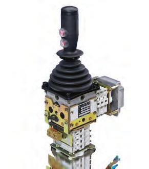


238
Setting big things into motion. Industrial Controllers Catalog 2018
 Setting big things into motion. Industrial Controllers Catalog 208 Product range Tool for Designers, Engineers and Purchasing Agents Your tool for finding industrial controllers for cranes, electro-hydraulic
Multi-axis controller V25
 The multi-axis controller is available in either single-axis or multi-axis options and is a robust controller used commonly in electro-hydraulic applications. With many output options including voltage,
Multi-axis controller V 8 / VV 8
 Multi-axis controller V 8 / VV 8 /30 03 The multi-axis controller V 8 is a rugged switching device according IEC/EN 947-5- for electro-hydraulic applications.the modular design enables the switching device
Section 2. Potentiometer HG 1 OEC 2 OEC 4 Electronic control unit MATRIX grip Hall-push button Palm grip Housing
 Section Potentiometer HG 1 OEC OEC 4 Electronic control unit MATRIX grip Hall-push button Palm grip Housing Product range Potentiometer HG 1 OEC OEC 4 Electronic control unit MATRIX grip Hall-push button
RT300 Series Crane & Hoist Joystick. RunnTech. Potentiometer: ±32, Hall sensor: ±20
 Electronics (Changzhou) Corp. RT00 Series Crane & Hoist Joystick RT00 Series Crane & Hoist Joystick Product Features Single axis or dual axis control; Pure silver contacts to ensure durable; Spring return
RT02 Series Robust Industrial Joystick. RunnTech
 Electronics (Changzhou) Corp. RT0 Series Robust Industrial Joystick RT0 Series Robust Industrial Joystick Product Features Potentiometer sensor or Hall sensor; Single axis, dual axis or axis control; Resistant
Angular Position Technology
 Inclinometers WHAT IS AN INCLINOMETER? Inclinometers measure angular tilt in reference to gravity. TURCK inclinometers contain a MEMS (Micro-Electro-Mechanical System) device that incorporates a microelectromechanical
Multi-axial miniature joystick based on Hall Effect technology
 Joystick with grip Multi-axial miniature joystick based on Hall Effect technology J... + space-saving design + highly reliable and long lifetime due to contactless Hall Effect technology + integrated third
Ergonomic joystick for parallel arrangement in the tightest installation spaces
 Robust joystick J7 Ergonomic joystick for parallel arrangement in the tightest installation spaces + Developed for adverse environmental conditions, protection class IP67 (electronic) + For forces up to
INTRINSICALLY SAFE INSTRUMENTATION FOR HAZARDOUS AREAS
 INTRINSICALLY SAFE INSTRUMENTATION FOR HAZARDOUS AREAS SHORT FORM 2002 SERIES D1000 Intrinsically Safe Galvanic Isolators SERIES D1000, for DIN Rail Mounting, provide the most simple and cost effective
VNSO MILL DUTY JOYSTICK CONTROLLER
 VNSO MILL DUTY JOYSTICK CONTROLLER Application: The type VNSO Joystick controllers are characterized by their unmatched versatility and rugged construction. They are actively providing directional and
TECHNICAL DATASHEET Heavy Duty - Absolute Encoder AR 62/63
 AR 6 Single and Multi turn: Resolution up to 8 Bit Wearless electronic multi turn: contact -and battery less, self-energetic 300 N axial and radial load 00 g shock resistance/ 0 g vibration resistance
Data Sheet. JS6000 Joystick Base
 Data Sheet JS6000 Joystick Base Mobile Machine Management The JS6000 joystick base is an element of the flexible, powerful, expandable, and affordable joystick family of mobile machine management products.
Switchgear and control equipment
 Switchgear and control equipment / Master controllers, differential limit switches / Summary / / Grab differential limit switch SJ /7 Crane controllers /7 Summary / Rotatable crane controller SJ9 0 / Contactors
HG series Hand grip Hall effect joysticks
 Distinctive features and specifications Rugged, hand operation Hall effect sensing Sealed up to IP68 1 million life cycles Redundant outputs available Analog, USB and custom outputs CANbus J1939 and CANopen
bidirectionally as well as the rotation sense of shafts. With absolute encoders instead, each incremental
 and draw-wire sensors Spot-on and trailblazing technology measure rotation speed, sense, position, angle and length. For this purpose, they convert mechanical motion in electrical signals. There are incremental
gsens Geometric Measurement
 Mobile Machine Control Solutions gsens Geometric Measurement Precise Reliable Multifunctional Good Work is Measurable gsens. Geometric Sensors from Hirschmann MCS Benefits of the gsens Sensors: Precise
Push-Pull and E-Stop Switches. Datasheet
 Push-Pull and E-Stop Switches Datasheet Honeywell Push-pull and E-stop switches are durable, environmentally sealed, sliding contact switches incorporating two circuits with multiple combinations. The
RLS - 51 Geared CAM Limit Switches
 RLS - 5 Geared CAM Limit Switches 2 Page Title www.powerjacks.com Power Jacks is the largest and most experienced manufacturer of actuators and mechanical jacks in the UK. Our products are used in a wide
Instruction book IQAN-LSL. Publ no HY /UK Edition 0301
 Instruction book IQAN-LSL Publ no HY17-8367/UK Edition 0301 Contents 1 Introduction......................................................2 2 Precautions.......................................................3
More than safety. Joystick Switches
 More than safety. Joystick Switches ManMachine More than safety. Emil Euchner, the company s founder and inventor of the multiple limit switch, circa 1928. Around the world the Swabian specialists in motion
Switching and controlling in the switch cabinet
 Switching and controlling in the switch cabinet Relays Opto-coupler Solid state relays Intelligent interface technology 02 03 MIRO INTERFACE TECHNOLOGY MINIMUM SPACE MAXIMUM FUNCTIONALITY Application areas
Linear Measurement Technology Draw Wire Mechanics with Encoder or Analog Sensor
 High IP protection rating Wide temperature range Shock/vibration resistant Reverse polarity protection Robust Corrosion resistant: Titanium-anodized aluminium housing. High-strength stainless steel draw
HG series Hand grip Hall effect joysticks
 Distinctive features and specifications Rugged, hand operation Hall effect sensing Sealed up to IP68 1 million life cycles Redundant outputs available Analog, USB and custom outputs CANbus J1939 and CANopen
LME620-AI/-AN (Contrac) Electrical Linear Actuator
 Electrical Linear Actuator") Contents Data Sheet Rev. A LME620-AI/-AN (Contrac) Electrical Linear Actuator For continuous positioning, Rated force 4 kn (900 lbf), With integrated electronics or for use with separate electronic unit
Contents Data Sheet Rev. A LME620-AI/-AN (Contrac) Electrical Linear Actuator For continuous positioning, Rated force 4 kn (900 lbf), With integrated electronics or for use with separate electronic unit
Instruction book IQAN-LST. Publ no HY /UK Edition 0301
 Instruction book IQAN-LST Publ no HY17-8364/UK Edition 0301 Contents 1 Introduction......................................................2 2 Precautions.......................................................3
HFX series I First generation Hall effect joysticks
 an APEM Group Company HFX series I The HFX Series I Joystick is designed for precision finger operated applications requiring proportional control and long trouble-free life. Featuring non-contacting Hall
Resolver to Digital Expansion Board
 Resolver to Digital Expansion Board Catalog No. EXB009A01 Installation and Operating Manual 6/98 MN1313 Table of Contents Section 1 General Information............................. 1-1 Introduction....................................
Linear Measurement Technology Draw Wire Mechanics with Encoder or Analog Sensor
 High IP protection rating Wide temperature range Shock/vibration resistant Reverse polarity protection Robust Corrosion resistant: Titaniumanodized aluminium housing. Highstrength stainless steel draw
English. Operating manual. Universal transmitter UT125. Save for later reference. Companies / brands of GHM
 English Operating manual Universal transmitter UT125 Companies / brands of GHM www.ghm-messtechnik.de Save for later reference. Table of contents page 1. Intended use (areas of application)... 3 1.1 Safety
MS series Mid-size Hall effect joysticks
 Distinctive features and specifications Compact size 1, 2 and 3 axis configurations Sealed up to IP68 Available with USB Redundant outputs available 1 million life cycles Available with J1939 CANbus and
RSTI-EP Slice I/O Digital Input Modules EP-1214, EP-1218, EP-1318, EP-125F, EP-1804 Digital Input Module with Time Stamp EP-12F4
 GFK-2975C August 2016 Module Status LED Channel Status LEDs Digital Input Connector Ground 24 V DC FE Digital Input Module RSTI-EP Slice I/O Digital Input Modules EP-1214, EP-1218, EP-1318, EP-125F, EP-1804
IV-30 Operating Manual for Pulse Distributor Cassette with potential separation
 IV-30 Operating Manual for Pulse Distributor Cassette with potential separation Edition-/Rev.-Date: 09/08/2006 Document-/Rev.-No.: TR - EAK - BA - GB - 0093-02 Software version: - File name: TR-EAK-BA-GB-0093-02.DOC
Technical Data Sheet OPUS A8 ECO Basic
 Industriestraße 7. 6566 Geisenheim. Germany Technical Data Sheet OPUS A8 ECO Basic 17.01.2018 Errors and technical changes excepted 1 Notes and Warnings Attention! This description is not a substitution
Available with actuator function: POWER OPEN - POWER CLOSE FAILSAFE MODULATING FAILSAFE MODULATING. Overview
 Feature rich J+J multi-voltage smart electric actuator with LED status light and function conversion kits. J3C-S20 Overview The J3C-S20 multi-voltage smart electric valve actuator from the European electric
USER MANUAL. WBI412F41 AC current transducer
 Designing, Manufacturing and Supplying WB Series Electric Isolated Sensor and Digital Electrical Transducer since 989 USER MANUAL WBI2F AC current transducer www.wb-my.com wblch@wbdz.cn Technical Service:
PRO-6 HEAVY-DUTY SINGLE AXIS JOYSTICK CONTROLLER
 PO-6 HEAVY-DUTY SINGLE AXIS JOYSTICK CONTOLLE PO-6 Single Axis Heavy-Duty Joystick PO-6H Single Axis Heavy-Duty Hall-effect Joystick Construction: The ultra-rugged PO-6 provides precise proportional control
Kinetix 6000 Axis Module and Shunt Module
 Installation Instructions Kinetix 6000 and Shunt Module Catalog Numbers 2094-AMxx, 2094-BMxx 2094-AMxx-S, 2094-BMxx-S 2094-BSP2 Topic Page About This Publication 1 Important User Information 2 Before You
Faults on the system Proximity switch connection technology:
 Speed monitor for connection to a base unit from the PNOZmulti modular safety system Approvals Unit features Monitoring of 2 independent axes Connection of 2 incremental encoders or 4 proximity switches
USER MANUAL. WBV412U01 AC voltage transducer
 Designing, Manufacturing and Supplying WB Series Electric Isolated Sensor and Digital Electrical Transducer since 1989 USER MANUAL WBV412U01 AC voltage transducer www.wb-my.com wblch@wbdz.cn Technical
Rotary Measurement Technology Absolute Encoders, Singleturn
 -20 to 85 C High rotational speed Temperature Shock/ vibration resistant Short-circuit proof Reverse polarity protection Rugged Highest shock resistance on the market: ( 200 g (2,500 m/s 2 )), 6 ms acc.
Robust precision. MAGRES EAM Magnetic absolute encoders.
 Robust precision MAGRES EAM Magnetic absolute encoders. Proven robustness. Highest precision up to ±0.15. MAGRES absolute encoders are well-proven under harsh conditions all over the world. The new generation
CJ series Ergonomic multifunction joysticks
 an APEM Group Company CJ series The CJ Series joystick features an ergonomic multifunction handle purposely designed for safety critical hand-operated applications. Available as a one or two axes joystick,
USER MANUAL. WBI414F21 AC current transducer
 1 Designing, Manufacturing and Supplying WB Series Electric Isolated Sensor and Digital Electrical Transducer since 1989 USER MANUAL WBI1F21 AC current transducer www.wb-my.com wblch@wbdz.cn Technical
DATASHEET ABSOLUTE MAGNETIC ROTARY ENCODER CANOPEN
 Robust rotary sensor based on reliable magnetic technology. Stainless steel housing capable to withstand extreme environmental conditions. Ideal suited for outdoor applications. Sturdy ball bearings for
VCSO COMPACT / RUGGED JOYSTICK CONTROLLER
 VCSO COMPACT / UGGED JOYSTICK CONTOLLE Construction: The TYPE VCSO Joystick Controller is rugged, compact and offers excellent application versatility. VCSO Joysticks are utilized where precise proportional
MVK Metall and Impact67 Compact Modules IP67
 MVK Metall and Impact67 Compact Modules IP67 Robust Vibration-proof Tight 2 MVK METALL Fully encapsulated metal housings for rough conditions 3 MVK METAL AND IMPACT67 THE COMPACT IP67 BUS MODULES Application
SENSORS INCLINOMETERS... SN4 LENGTH AND ANGLE SENSORS... SN6 SLIP-IN SPOOL POSITION TRANSDUCER... SN8 PROXIMITY SENSOR... SN10 MATERIAL SENSOR...
 Section / Description page INCLINOMETERS... SN4 LENGTH AND ANGLE SENSORS... SN6 SLIP-IN SPOOL POSITION TRANSDUCER... SN8 PROXIMITY SENSOR... SN10 MATERIAL SENSOR... SN11 ACCESSORIES... SN12 Page SN1 Page
Draw wire sensors, draw wire sensors for displacement, position
 Draw wire sensors, draw wire sensors for displacement, position Sensors based on potentiometer and encoder, for industrial and OEM applications for measurement of lengths, stroke, displacement, position,
More Precision. wiresensor // Draw-wire displacement sensors
 More Precision wiresensor // Draw-wire displacement sensors 24 Low-cost draw-wire displacement sensors wiresensor MK analog - Robust plastic housing - Customized versions for OEM - Potentiometer, current
PAS 300, PROFIBUS Slave Interface Module
 Catalog 08 PROFIBUS-Components 27 PAS 300, PROFIBUS Slave Interface Module PROFIBUS PROFIBUS slave interfaces PROFIBUS slave module The PROFIBUS slave interface module PAS 300 from the Systeme Helmholz
Vert-X 32E - 24V / CANopen, redundant. Applications Forklifter Platformer Agricultural machine. Features. CiA approved CiA V402/
 Sensor principle MH-C2 Electrical data Measuring range 0... 360 Indep. linearity (typ.) % of meas. range ±0.3 Max. hysteresis 0.1 Resolution bit 16 Max. repeatability 0.1 Sample rate khz 0.5 Max. temperature
XPSMF35. Product data sheet Characteristics. Preventa safety PLC compact - Profibus DP protocol. Main. Complementary. Safety module name
 Product data sheet Characteristics XPSMF3542 Preventa safety PLC compact - Profibus DP protocol Main Range of product Product or component type Safety module name Safety module application Nov 13, 2018
JS120 Single Axis Fingertip Joystick. Technical Information
 JS120 Single Axis Fingertip Joystick Technical Information Revisions Version Revisions Date Page Change Rev. 13 Feb, 2007 Lever length options; connector pin assignments Rev-CA 12 May, 2006 7 Model code
Technical Data Sheet OPUS A3 STANDARD Basic
 Technical Data Sheet OPUS A3 STANDARD Basic 17.01.2018 Errors and technical changes excepted 1 Notes and Warnings Attention! This description is not a substitution for the concerned product s documentation.
Technical Data Sheet OPUS A3 ECO Full
 Technical Data Sheet OPUS A3 ECO Full 17.01.2018 Errors and technical changes excepted 1 Notes and Warnings Attention! This description is not a substitution for the concerned product s documentation.
A new eneration of. professional control E / Plug & Work. An excellent control to mobilize your visions ON/OFF PWM
 A new eneration of professional control ON/OFF PWM Plug & Work An excellent control to mobilize your visions The new joystick controller unit G-pro combines the flexible functionality of a remote control
07. har-link INTERFACE CONNECTORS
 . INTERFACE CONNECTORS The highest data rates in combination with perfect shielding characterize the connector. This way data can be passed on optimally within the control cabinet. The locking mechanism
For information about the products exhibited: Walvoil Fluid Power Corp North Garnett Tulsa OK USA Tel Fax
 For information about the products exhibited: Walvoil Fluid Power Corp. 4111 North Garnett Tulsa OK 74116 USA Tel. 918.858.7100 Fax 918.858.7150 1109 Technology Drive Red Wing MN 55066 USA Tel. 651.212.6400
Technical Data Sheet OPUS A8 ECO Full
 Technical Data Sheet OPUS A8 ECO Full 21.09.2017 Errors and technical changes excepted 1 Notes and Warnings Attention! This description is not a substitution for the concerned product s documentation.
Analog display for resistance current
 www.reinhausen.com Analog display for resistance current Operating Instructions BA 2220061/01 NOTE The product may have been modified after this document went to press. We expressly reserve the right to
AMG 11. Features. Optional. Additional incremental output (TTL / HTL) AMG 11. Technical data - mechanical design. Technical data - electrical ratings
 AMG 11. Technical data - mechanical design. Technical data - electrical ratings") Features Multiturn SSI / Profibus / CANopen / DeviceNet / PROFINET Optical sensing method Singleturn 1 bit, multiturn 1 bit / 16 bit EURO-flange B10 / solid shaft ø11 mm Multiturn sensing with microgen
Features Multiturn SSI / Profibus / CANopen / DeviceNet / PROFINET Optical sensing method Singleturn 1 bit, multiturn 1 bit / 16 bit EURO-flange B10 / solid shaft ø11 mm Multiturn sensing with microgen
NOVOHALL Rotary Sensor non-contacting. Series RSX-7900
 NOVOHALL Rotary Sensor non-contacting Series RSX-7900 Special features very robust design to extreme environmental conditions high shaft load 300 N non-contacting, magnetic measuring angles up to 360 in
MultiViu Flex 4 Data Sheet
 Division Interior MultiViu Flex 4 Data Sheet Description CAN-capable multifunction Solution Features: Robust and versatile design CAN-capability (SAE J1939, CANopen) Video interface Analogue and digital
P/N: AX Distribute your control functions directly onto the valve.
 TECHNICAL DATASHEET #TDAX022311 Dual Plug-In Valve Controller, CANopen 2-2.5A Outputs Programmable Distribute your control functions directly onto the valve. P/N: AX022311 Features: Configurable for 1
DF PROFI II PCIe. Installation Instructions V Project No.: 5302 Doc-ID.: DF PROFI II PCIe KUNBUS
 DF PROFI II PCIe Installation Instructions V1.6 27.02.2017 Project No.: 5302 Doc-ID.: DF PROFI II PCIe KUNBUS h:\dokumente\project\5302_df_profi_ii\anwenderdoku\installation\pcie\kunbus\version_1.5\df
24/48/120 VAC Interface Card Instruction Manual
 24/48/120 VAC Interface Card Instruction Manual Distributed by Ergonomic Partners Sales@ErgonomicPartners.com www.ergonomicpartners.com Tel: (314) 884-8884 April 2012 Part Number: -R2 Copyright 2012 Magnetek
Data Sheet for Joysticks
 Different handle designs available Optionally with Pushbuttons and Deadman Industrial-suited robust design IP classes up to 68 (on request) Several Output Options (analog, CAN J1939, CANopen, USB) The
SINAMICS G130. Terminal Module 150 (TM150) Operating Instructions 03/2013 SINAMICS
 Operating Instructions 03/2013 SINAMICS") SINAMICS G130 Operating Instructions 03/2013 SINAMICS s Safety information 1 General information 2 SINAMICS SINAMICS G130 Mechanical installation 3 Electrical installation 4 Technical specifications 5
SINAMICS G130 Operating Instructions 03/2013 SINAMICS s Safety information 1 General information 2 SINAMICS SINAMICS G130 Mechanical installation 3 Electrical installation 4 Technical specifications 5
Data Sheet for Joysticks
 Finger Joystick Series 8 Dual redundant outputs IP6 sealed lever heights: 8mm and 60mm 5 lever colors Series 8 is offering paddle joysticks of high precision and quality - claims that are not only supported
Data Sheet for Joysticks
 Finger Joystick Series 87 Dual redundant outputs IP67 sealed lever heights: 8mm and 60mm 5 lever colors Series 87 is offering paddle joysticks of high precision and quality - claims that are not only supported
I E D C E R T. Net MA N A G E ME N T S Y S T E M ISO 9001: 2000 RAVI Joystick Controllers COMPACT Series
 C E R T I F MA N A G E ME N T I E D Net ISO 9001: 2000 RAVI 9105 I S Y S T E M Joystick Controllers COMPACT Series 6 Joystick Controllers COMPACT Series - GMC types Main Features The range of joysticks
JS120 Single Axis Fingertip Joystick. Technical Information
 JS120 Single Axis Fingertip Joystick Technical Information Revisions Version Revisions Date Page Change Rev. 2 July, 2009 8, 11 Corrected connector pin assignments and added output voltage curve DA 13
Digital Output Module 8-Channel Version for Zone 2 Series 9475/
 > 8-channel digital output > Intrinsically safe outputs Ex ia > For Ex i solenoid valves and display elements > Line fault monitoring per channel > Diagnostics based on NE107 > Module can be replaced in
Analog electric proportional joysticks JEP
 Analog electric proportional joysticks JEP 2.01.09 Index: Description: Page 3 Technical features: Page 4 Metering curve: Page 5 Overall dimensions: Pages 6 9 Control handles: Page 10 Rubber boot: Page
Analog micro push button
 Analog micro push button for rugged applications 145MA... + 0.5...4.5 V DC analog output at 5 ± 0.5 V DC operating voltage + output signal can be adjusted within the voltage range + non-contact operation
Field bus connections Link structure BDC Link structure BDC, B-design. Brochure
 Field bus connections, B-design Brochure Field bus connections, B-design Bus coupler with driver Direct field bus connection (BDC) Bus coupler with driver direct field bus connection Field bus protocol:
More Precision. wiresensor // Draw-wire displacement sensors
 More Precision wiresensor // Draw-wire displacement sensors 22 Low-cost draw-wire displacement sensors wiresensor MK88 analog - Robust plastic housing - Customized versions for OEM - Potentiometer, current
EM-F-7G Safety Extension Module
 EM-F-7G Safety Extension Module One-channel control with four safety output channels Features Safety Extension Module provides additional safety outputs for a Primary Safety Device (for example, an E-stop
APPLICATION GUIDE. Interface Modules IM Series.
 Interface Modules IM Series APPLICATION GUIDE www.turck.com Interface Technology Interface Modules TURCK's IM series of Isolating Intrinsically Safe Barriers is designed to be a simple and safe way to
TURCK Process Automation IS Interface Technology. Interface Modules. IM Series Cabinet
 Process Automation IS Interface Technology Interface Modules TURCK's IM series of Isolating Intrinsically Safe Barriers is designed to be a simple and safe way to solve the problems associated with the
Robust precision. MAGRES EAM Magnetic absolute encoders.
 Robust precision MAGRES EAM Magnetic absolute encoders. Proven robustness. Highest precision up to ±0.15. MAGRES absolute encoders are well-proven under harsh conditions all over the world. The new generation
PI-EX-ME-2NAM/COC-24VDC
 Ex-i NAMUR Isolation Amplifier, With Intrinsically Safe Input and Relay Output, PDT, Two-Channel, 4 V DC Supply INTERFACE Data Sheet 0033_0_en PHOENIX CONTACT - /007 Description The PI-EX-ME-NAM/COC-4VDC
4/0 EASY control relay
 4/0 DEL ALT ESC OK Contents 4/1 Page System overview 4/2 4/4 EASY800 networking 4/4 4/5 Basic units 4/5 Expansion units 4/9 Multi-function display 4/8 Display/operator unit 4/8 Power supply/cpu modules
Intelligent Positioning Drive GEL 6111 CANopen, PROFIBUS DP, Ethernet etc.
 Intelligent Positioning Drive GEL 6111 CANopen, PROFIBUS DP, Ethernet etc. Technical Information Version 11.10 Features Nominal torque 5 Nm Self-locking system for wear-free holding torque On-board controls
OTB1C0DM9LP I/O distributed module OTB - CANopen bus m
 Characteristics I/O distributed module OTB - CANopen bus - 0..1000 m Main Range of product Product or component type Integrated connection type Bus type Jan 28, 2018 Modicon OTB I/O distributed module
Dual Channel Monitor for Measurement of Speed and Ratio with SIL1 requirements Series D224.xx
 D224 Dual Channel Monitor for Measurement of Speed and Ratio with SIL1 requirements Series D224.xx D224 Front View KEY FEATURES SIL1 / IEC 61508:2010 compliant Dual Channel Speed and Ratio Monitor with
L-force. Inverter Drives 8400 protec. On site and all systems go!
 L-force Inverter Drives 8400 protec On site and all systems go! 2 L-force Decentralised drives 2 The major challenges of the future are to be found in the areas of cost efficiency, time-saving and quality
Control unit SG-EFS 104/2W. EN Operating instructions. Innovative by tradition. Version SG-EFS 104/2W 24 V=/~
 Innovative by tradition. Control unit SG-EFS 104/2W EN Operating instructions Version 0.9 1005196 SG-EFS 104/2W 24 V=/~ Original instructions Mayser GmbH & Co. KG Örlinger Straße 1 3 89073 Ulm GERMANY
Installation Manual Series PQ-L. Electronic Module. Bulletin /UK
 Bulletin 5715-571 /UK Installation Manual Electronic Module Gutenbergstr. 38 41564 Kaarst, Germany Tel.: (+) 2131-513-0 Fax: (+) 2131-513-230 www.parker.com Copyright Ó 2000, Note This document and other
Single Phase Systems-North American PC125/PC420 Series
 Single Phase Systems-North American PC125/PC420 Series Enclosure Power Distribution Units (epdu ) PC125-C Front RACK MOUNTED 19 x 3.4 (2U) x 8.5. Approximate shipping weight: 19 lbs. (12) NEMA OUTLETS
PCB Terminals and Connectors. Capabilities Brochure. Phone: Fax: Web: -
 PCB Terminals and Connectors Capabilities Brochure Connectivity Solutions are a Matter of... Application Knowledge With over 60 years in the industry, Weidmuller offers unmatched depth in thousands of
PANEL ENCODERS. Optical and magnetic Encoders, potentiometric Setpoint Adjusters and Adjustment Knobs
 PANEL ENCODERS Optical and magnetic Encoders, potentiometric Setpoint Adjusters and Adjustment Knobs www.megatron.de Optical Encoders with increased Torque Optical encoder with increased torque, high resolution
Rotary Measuring Technology Absolute encoders, Multiturn, DeviceNet
 High IP High shaft load capacity Shock/vibration resistant Short-circuit proof Reverse polarity protection Compact and Rugged: Minimal installation depth High shock and vibration values Very compact (only
Operating Instructions Differential Pressure Transducer PS27
 Operating Instructions Differential Pressure Transducer PS27 halstrup-walcher GmbH Stegener Straße 10 79199 Kirchzarten/Germany Phone: +49 (0) 76 61/39 63 0 Fax: +49 (0) 76 61/39 63 99 E-mail: info@halstrup-walcher.com
SafeC S. Features. Typical Applications. Technical Data. Principle. Safety Relay
 EN 954 SafeC S Safety Relay SafeC S: Narrow construction of only 22.5 mm SafeC S is a sturdy and extremely inexpensive safety relay which impresses with its unusual efficiency and versatility, despite
Technical Data Sheet OPUS A6 ECO Full
 Technical Data Sheet OPUS A6 ECO Full 07.08.2015 Errors and technical changes excepted 1 Notes and Warnings Attention! This description is not a substitution for the concerned product s documentation.
ACS HEAVY DUTY INCLINOMETER SAE J1939 INTERFACE
 ACS HEAVY DUTY INCLINOMETER ACS Heavy Duty inclinometers from POSITAL are robust inclination sensors specially designed for applications involving rough handling and exposure to rigorous conditions. The
MBS1250 Heavy Duty Pressure Transmitter. Product Electrical Installation
 MBS1250 Heavy Duty Pressure Transmitter Product Electrical Installation Revisions Revisions History Table of Revisions Date Page Changed Rev 20 Feb, 2009 AA 2009 Sauer-Danfoss. All rights reserved. Sauer-Danfoss
PHOENIX CONTACT - 11/2007. This data sheet is only valid in association with the IB IL SYS PRO UM E user manual.
 INTERBUS Inline Bus Coupler; Remote Bus Connections Via D-SUB Connectors REMOTE IN BA UL RD RC DSUB LD AUTOMATIONWORX Data Sheet 6362_en_03 PHOENIX CONTACT - 11/2007 REMOTE OUT Description The bus coupler