RER 123 Bus Connection Module. Technical Description
|
|
|
- Kellie Stanley
- 6 years ago
- Views:
Transcription
1 Bus Connection
2
3 1MRS MUM Issued: Version: E/ Bus Connection 1. About this manual Copyrights Trademarks Guarantee Safety information General Principle of operation Construction and mounting Type designation Fibre-optic connectors and technical data...11 Copyright 2005 ABB Oy, Distribution Automation, Vaasa, FINLAND 3
4 Bus Connection 1MRS MUM 1. About this manual 1.1. Copyrights 1.2. Trademarks 1.3. Guarantee The information in this document is subject to change without notice and should not be construed as a commitment by ABB Oy. ABB Oy assumes no responsibility for any errors that may appear in this document. In no event shall ABB Oy be liable for direct, indirect, special, incidental or consequential damages of any nature or kind arising from the use of this document, nor shall ABB Oy be liable for incidental or consequential damages arising from use of any software or hardware described in this document. This document and parts thereof must not be reproduced or copied without written permission from ABB Oy, and the contents thereof must not be imparted to a third party nor used for any unauthorized purpose. The software or hardware described in this document is furnished under a license and may be used, copied, or disclosed only in accordance with the terms of such license. Copyright 2005 ABB Oy All rights reserved. ABB is a registered trademark of ABB Group. All other brand or product names mentioned in this document may be trademarks or registered trademarks of their respective holders. Please inquire about the terms of guarantee from your nearest ABB representative. 4
5 1MRS MUM Bus Connection 2. Safety information Dangerous voltages can occur on the connectors, even though the auxiliary voltage has been disconnected. National and local electrical safety regulations must always be followed. The device contains components which are sensitive to electrostatic discharge. Unnecessary touching of electronic components must therefore be avoided. Only a competent electrician is allowed to carry out the electrical installation. Non-observance can result in death, personal injury or substantial property damage. 5
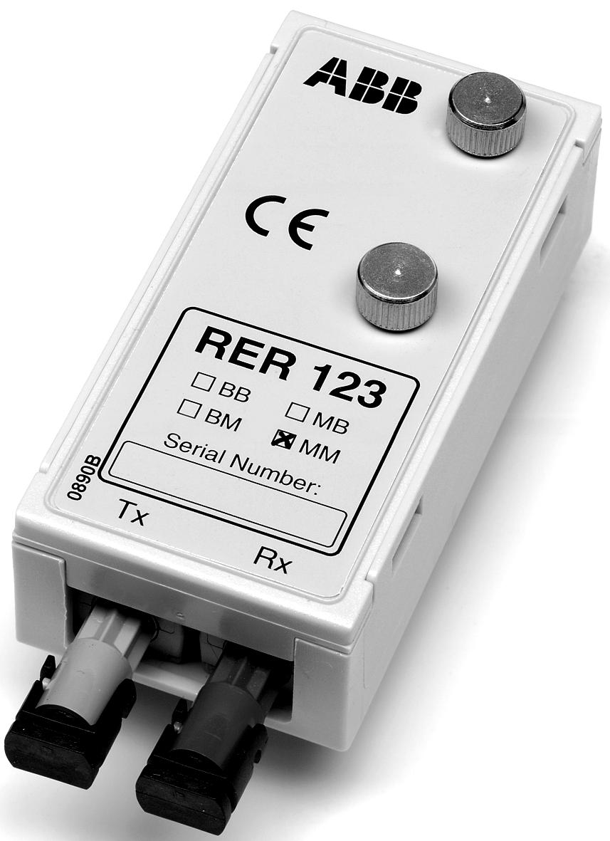
6 Bus Connection 1MRS MUM 3. General The bus connection module acts as an interfacing unit between an RE_ 54_ device and a fibre-optic SPA, DNP 3.0, Modbus or IEC bus. The bus connection module converts incoming optical signals from the bus to electrical RS-232 signals for the RE_ 54_ devices and vice versa. The module is connected to a host device with a 9-pin D-type RS-232 connector on the rear plate of the RE_ 54_ device via a cable delivered with the module. It can be used together with any RE_ 54_ device provided with a 9-pin D-type RS-232 connector. The bus connection module is also powered from the same D-type connector of the RE_ 54_ device. The box includes a bus connection module (), a connection cable, two jumpers, and an installation plate. The RS-232 interface of the bus connection module is shown in the figure below. Rx Tx D9 male connector Pin Signal 1 n.c. = not connected 2 RXD 3 TXD V DC 5 GND 6 connected to pin 7 7 connected to pin 6 8 n.c. 9 n.c. RS232 D9P-connector A A Fig pin D-type connector and block diagram. 6

7 1MRS MUM Bus Connection 4. Principle of operation The bus connection module can be used in Loop and Star type bus topologies. Also the line idle state of the module is selectable. It can be light on or off. The selection of Loop/Star and light on/off is made by jumpers. In the Loop topology the module passes a message received from the fibreoptic interface both to the fibre-optic transmitter and the RS-232 interface. In the Star topology the module passes a message received from the fibre-optic receiver only to the RS-232 interface. A message received from the RS-232 interface is passed to the fibre-optic transmitter in both bus topologies. SPA bus communication is using Loop and light off modes, when the module jumpers are in Loop and light off positions. IEC_103 bus communication is using Star and light on or off modes, when the module jumpers are in Star and light on or off positions. DNP 3.0 and Modbus support all jumper combinations. Fig Rear side of the module A Table 4.-1 Settings of the jumper Topology Light on/off Protocol Star Off IEC_103, DNP 3.0, Modbus Star LIght IEC_103, DNP 3.0, Modbus Loop Off SPA, DNP 3.0, Modbus Loop Light DNP 3.0, Modbus 7
8 Bus Connection 1MRS MUM 5. Construction and mounting The consists of a printed circuit board and is housed in a plastic case. It can be mounted on the rear side of the RE_ 500 device by using the mounting plate and cable delivered with the module. See Figure Fig Dimensional drawing of the bus connection module A Fig Mounting of the A
9 1MRS MUM Bus Connection Connect the cable between the device and the bus connection module and lock it by tightening the finger screws in both ends. To meet the specified EMC requirements, only the connection cable (1MRS120524) delivered with the module may be used between the and the device. The incoming optical fibre is connected to the receiver input Rx and the outgoing optical fibre to the transmitter output Tx. Special attention must be paid to the handling, mounting, connection, etc. of optical fibres. The can be provided with connectors for two plastic fibre cables, two glass fibre cables or one of each type. For additional information, refer to the manual Plastic-core fibre-optic cables. Features and instructions for mounting (34 SPA 13 EN1). 9
10 Bus Connection 1MRS MUM 6. Type designation Type designation Transmitter Receiver Ordering number Plastic Plastic RER123-BB Plastic Glass RER123-BM Glass Plastic RER123-MB Glass Glass RER123-MM The IEC star-coupler RER 125 supports only glass-glass and plastic-plastic transceiver connections. RER123-MB Type Optical receiver: B = plastic fibre cable M = glass fibre cable Optical transmitter: B = plastic fibre cable M = glass fibre cable A
11 1MRS MUM Bus Connection 7. Fibre-optic connectors and technical data Table 7.-1 Fibre-optic connectors Glass fibre Plastic fibre Cable connector ST connector snap-in connector Cable diameter 62.5/125 um 1 mm Max. cable length 1000 m 20 m Wavelength nm 660 nm Transmitted power -13 dbm (HFBR-1414) -13 dbm (HFBR-1521) Table 7.-2 Technical data Auxiliary power supply Powered from a host device (9/15 V DC) Burden ~ 1.2 W Max. data transfer rate 19.2 kbps Mechanical dimensions Width: 35.0 mm Height: 73.0 mm Depth: 20.0 mm Operating temperature range Storage temperature range with RE_ 54_ Connection cable 1MRS o C o C Width: 25 cm Length: mm 11
12 ABB Oy Distribution Automation P.O. Box 699 FI Vaasa FINLAND Tel Fax MRS MUM EN
SPA-ZC 200/SPA-ZC 202 IEC /SPA-gateway Modules. Installation Manual
 Issued: 29.03.2001 Version: A/29.03.2001 Checked: M.K. Approved: We reserve the right to change data without prior notice. Contents: 1. Safety information...4 2. Introduction...5 2.1. Contents of delivery...5
SPA-ZC 17. Bus connection module SPA-ZC 17. User s manual and Technical description. Tx SC Rx BB BM MB MM SPA / RS 485 POWER SLAVE 1 MASTER 0
 SPA-ZC 17 Bus connection module User s manual and Technical description 1 2 3 4 5 6 7 8 O N SPA / RS 485 SPA 1100000 RS 485 0011110 SLAVE 1 MASTER 0 Tx SC Rx 2 5 Uaux 80...265 V ~ 18...80 V SPA-ZC 17 RS
SREDU Double Connection Option Card for Lon Star Coupler RER 111
 SREDU Lon Star Coupler RER 111 Technical Reference Manual ABB Automation 1MRS 750108-MUM Issued: 21.11.1996 Version: B2/18.2.2000 Checked: M.K. Approved: T.S. Technical Reference Manual SREDU We reserve
Protection Relay RE_ 610. Installation Manual
 RE_ 0 MRS-MUM Issued:..00 Version: E/0..00 RE_ 0 Contents Copyrights.... Introduction........ This manual........ Use of symbols........... Intended audience........ Product documentation........... Document
Synchro-check relay. Application
 Issued: April 1999 Status: Updated Version: B/08.11.2001 Data subject to change without notice Features Two identical operation stages allowing the closing conditions of two separate circuit breakers to
Sensitive Earth-fault Relay SPAJ 111 C. Product Guide
 Issued: April 1999 Status: Update Version: C/12.04.2006 Data subject to change without notice Features Sensitive low-set neutral overcurrent stage with definite time characteristic High-set neutral overcurrent
Overcurrent and Earth-Fault Relay REJ 525. Technical Reference Manual
 Overcurrent and Earth-Fault Relay MRS75094-MUM Issued: 4.09.998 Version: D/4..2005 Overcurrent and Earth-Fault Relay Contents. About this manual...5.. Copyrights...5.2. Trademarks...5.3. Guarantee...5.4.
800xA Networks. NE801 User Manual. Power and productivity for a better worldtm
 800xA Networks NE801 User Manual Power and productivity for a better worldtm 800xA Networks NE801 User Manual NOTICE This document contains information about one or more ABB products and may include a
Voltage regulator. SPAU 341 C 1MRS MBG Issued: July 1998 Status: Revised Version: C/ Data subject to change without notice
 Issued: July 1998 Status: Revised Version: C/08.10.2003 Data subject to change without notice Features Comprehensive voltage regulation for power transformers with on-load tapchangers in distribution substations
Protection System Simulator SIM600. Installation Manual
 Protection System Simulator SIM600 1MRS756102 Issued: 08.12.2008 Version: B Protection System Simulator SIM600 Contents: 1. About this manual... 5 1.1. Copyrights... 5 1.2. Trademarks... 5 1.3. Guarantee...
LON bus communication devices 1MRS MBG Page 1 Issued: April 1999 Status: New Data subject to change without notice
 LON bus communication devices Page 1 Issued: April 1999 Status: New Data subject to change without notice Features The LonWorks Network is an open system adapted for various application areas Peer-to-peer
Earth-fault Relay SPAJ 110 C. Product Guide
 Issued: April 1999 Status: Updated Version: C/12.04.2006 Data subject to change without notice Features Low-set neutral overcurrent stage with definite time or inverse time characteristic High-set neutral
ABB Drives. User s Manual Modbus Adapter Module FMBA-01
 ABB Drives User s Manual Modbus Adapter Module FMBA-01 Modbus Adapter Module FMBA-01 User s Manual 3AFE68586704 REV A EN EFFECTIVE: 27.06.2005 2005 ABB Oy. All Rights Reserved. 5 Safety instructions
Feeder protection relay SPAA 121 C. Product Guide
 Issued: April 1999 Status: Updated Version: C/06.03.2006 Data subject to change without notice Features Two-phase low-set phase overcurrent unit with definite time or inverse time characteristic Two-phase
Data communication and reporting unit
 SRIO 500M Data communication and reporting unit User s manual and Technical description SRIO 500M FAULT ON 1 2 SERIAL IF 4 LOCAL 1 2 3 4 5 6 7 8 1 0 0542A 1MRS 750540-MUM EN Issued 1996-10-23 Modified
Sensitive definite time or inverse time earth-fault stage for back-up residual earthfault
 Issued: April 1999 Status: Updated Version: B/09.11.2001 Data subject to change without notice Features Sensitive restricted earth-fault protection stage for fast, selective earth-fault protection Sensitive
Residual overvoltage relay
 Page 1 Issued: April 1999 Status: New Data subject to change without notice Features Definite-time residual overvoltage earthfault protection and supervision Two independent operation stages, e.g. one
ABB ABB Oy, Distribution Automation
 ABB ABB Oy, Distribution Automation Guideline Issued: May 2012 Revision: A / 15 May 2012 COM600 Engineering process overview Engineering approach with.cid files in the SAB600 tool Contents: 1 Scope...
ABB Drives. User s Manual I/O Module Adapter AIMA-01
 ABB Drives User s Manual I/O Module Adapter AIMA-01 I/O Module Adapter AIMA-01 User s Manual 3AFE 64661442 REV A EN EFFECTIVE: 1.12.2003 2003 ABB Oy. All Rights Reserved. 5 Safety instructions Overview
Combined Overcurrent and Earth-fault Relay SPAJ 140 C. Product Guide
 Combined Overcurrent and Earth-fault Product Guide Issued: April 1999 Status: Updated Version: C/18.04.2006 Data subject to change without notice Features Three-phase, low-set phase overcurrent unit with
Data communication and reporting unit
 FAULT SRIO 1000M Data communication and reporting unit User s manual and Technical description SRIO 1000M ON 1 2 SERIAL IF 4 LOCAL 1 2 3 4 5 6 7 8 1 0 0543A 1MRS 750533-MUM EN Issued 1996-10-23 Modified
COM600 Station Automation Series MNS is Connectivity (OPC) 3.2. User's Guide
 3.2. User's Guide") MNS is Connectivity 3.2 User's Guide 1MRS756569 Issued: 17.06.2008 Version: A/17.06.2008 User's Guide MNS is Connectivity 3.2 Contents: 1. About this manual... 5 1.1. Copyrights... 5 1.2. Trademarks...
MNS is Connectivity 3.2 User's Guide 1MRS756569 Issued: 17.06.2008 Version: A/17.06.2008 User's Guide MNS is Connectivity 3.2 Contents: 1. About this manual... 5 1.1. Copyrights... 5 1.2. Trademarks...
Connectivity Packages. User's Guide - ANSI Version
 Connectivity Packages 1MRS756194 Issued: 30.11.2006 Version: A/30.11.2006 Connectivity Packages Contents Copyrights... 5 1. Introduction...... 7 1.1. Intended audience...... 7 1.2. Related documents.........
Combined Overcurrent and Earth-fault Relay SPAJ 141 C. Product Guide
 Combined Overcurrent and Earth-fault Product Guide Issued: April 1999 Status: Updated Version: C/19.04.2006 Data subject to change without notice Features Three-phase, low-set phase overcurrent unit with
Installation Instructions
 TM Installation Instructions Manual 10 - Star Driver Modules PY-STR, PY-STR-L, PY-STR-H and PY-STR-2-H Read also: Installation Instructions, Manual 2 - Network Wiring Please read this manual completely
DDR. User s Guide ND040012E. We reserve all rights in this document and in the information contained therein. Copyright 2014 Newcon Data AB
 DDR User s Guide ND040012E ND040012E Version: 2.0 Date: 24.03.2014 22:40:00 Use of DANGER, WARNING, CAUTION, and NOTE This publication includes DANGER, WARNING, CAUTION, and NOTE information where appropriate
Feeder protection relay SPAA 341 C. Product Guide
 Issued: April 1999 Status: Updated Version: D/07.03.2006 Data subject to change without notice Features Comprehensive numerical feeder protection relay consisting of two multi-function protection relay
Arc protection relay. Features Three-phase overcurrent function. Application
 Arc protection relay REA 10_ Issued: May 1999 Status: Updated Version: B/12.11.2001 Data subject to change without notice Features Three-phase overcurrent function Loop-type or radial sensor fibre for
Ethernet Adapter. Modbus/TCP Brigde. Installation and Commissioning Manual
 SPA-ZC 400 1MRS756014 Issued: 30.06.2006 Version: B/20.05.2009 SPA-ZC 400 Contents Copyrights... 5 1. Introduction...7 1.1. This manual... 7 1.2. Use of symbols... 7 1.3. Intended audience... 7 1.4. Product
ABB Drives. User s Manual. Modbus Adapter Module RMBA-01
 ABB Drives User s Manual Modbus Adapter Module RMBA-01 Modbus Adapter Module RMBA-01 User s Manual 3AFE 64498851 REV A EN EFFECTIVE: 1.3.2002 2002 ABB Oy. All Rights Reserved. Safety instructions Overview
InView Communication Modules
 Installation Instructions InView Communication Modules Catalog Numbers 2706-PxM, 2706-PxK, 2706-PxP Topic Page About This Publication 1 Important User Information 2 Power Supply Requirements 3 Mount the
Motor Control and Protection Unit M10x AO Module User Guide
 Motor Control and Protection Unit M10x AO Module User Guide The information in this document is subject to change without notice and should not be construed as a commitment by ABB. ABB assumes no responsibility
Arc protection relay. Features Three-phase overcurrent function. Application
 Arc protection relay REA 10_ Page 1 Issued: May 1999 Status: New Data subject to change without notice Features Three-phase overcurrent function Loop-type or radial sensor fibre for arc detection Two high-speed
COM600 Station Automation Series External OPC Client Access 3.1. User's Guide
 COM600 Station Automation Series External OPC Client Access 3.1 1MRS755564 Issued: 10.03.2005 Version: C/21.12.2007 COM600 Station Automation Series External OPC Client Access 3.1 Contents: 1. About this
REDUNDANCY MODULE TSP-REM360 AND TSP-REM600
 REDUNDANCY MODULE TSP-REM360 AND TSP-REM600 Operating Instructions Seite 1 Dimensions drawings: TSP-REM360 Weight: 0.882lb Gewicht: 0.40kg Seite 2 Dimensions drawings: TSP-REM600 Bottom view Top view Side
ABB Drives. User s Manual. Analogue I/O Extension Module RAIO-01
 ABB Drives User s Manual Analogue I/O Extension Module RAIO-01 Analogue I/O Extension Module RAIO-01 User s Manual 3AFE 64484567 REV A EN EFFECTIVE: 1.2.2002 2002 ABB Oy. All Rights Reserved. Safety
ABB Drives. User s Manual. Digital I/O Extension Module RDIO-01
 ABB Drives User s Manual Digital I/O Extension Module RDIO-01 Digital I/O Extension Module RDIO-01 User s Manual 3AFE 64485733 REV B EN EFFECTIVE: 10.2.2003 2003 ABB Oy. All Rights Reserved. Safety Instructions
SMS 510, CAP 505 LON Gateways Configuration Configuration Guide
 SMS 510, Industrial IT enabled products from ABB are the building blocks for greater productivity, featuring all the tools necessary for lifecycle product support in consistent electronic form. 1MRS751870-MEN
ABB i-bus KNX Switch Actuator, x-fold, 16 A, MDRC SA/S x , 2TAZ710xx1R2161
 Technical Data 9AKK107045A4913 ABB i-bus KNX Product description Switch Actuators SA/S x.16.2.1, 16 A are modular installation devices in ProM design for installation in the distribution board. They are
W&T. Universal Fiber Optic Interface Converter W&T. Manual. Universal FO Interface Converter. Model Release 1.0. Subject to error and alteration
 Manual Universal FO Interface Converter Model 81215 Release 1.0 Subject to error and alteration 13 10/2012 by Wiesemann & Theis GmbH Subject to error and alteration: Since it is possible that we make mistakes,
MEC-COM-M154. User s Manual
 MEC-COM-M154 Mini PCI-e 2-port RS-232 and 2-port RS232/422/485 serial board with power input User s Manual Third Edition, February 2014 2014 Cervoz Co., Ltd. All rights reserved. Reproduction without permission
ABB i-bus KNX DALI Light Controller, 8-fold, MDRC DLR/S M, 2CDG110101R0011
 Technical data 2CDC507101D0202 ABB i-bus KNX Product description The ABB i-bus KNX DALI Light Controller DLR/S 8.16.1M is a KNX modular installation device (MDRC) in ProM design for installation in the
Manual Fiber Optic Interfaces
 Manual Fiber Optic Interfaces Type 81210, 81211 61210, 61211 65210, 65211 41210 Release 1.4 Subject to error and alteration 31 06/2007 by Wiesemann & Theis GmbH Subject to error and alteration: Since it
Communication Gateway COM 500. Product Guide
 Communication Gateway COM 500 Product Guide Communication Gateway COM 500 1MRS750446-MBG Issued: May 1999 Status: Updated Version: B/16.11.2001 Data subject to change without notice Features Communication
Rhino Redundancy Module PSM24-REM360S. Operating Instructions
 Rhino Redundancy Module PSM4-REM360S Operating Instructions RHINO REDUNDANCY MODULE PSM4-REM360S Description With this module and two power supplies of the PSM series (78, 90, 56, 80 and 360 watt models),
CMU 100 RS232 to Singlemode Fiber Optic Converter User Manual
 CMU 100 RS232 to Singlemode Fiber Optic Converter User Manual CMU 100 / 1.1.S - 0 CMU 100 / 7.1.S - 0 Company: Device: Document: Code: Version: Date: Ediseja 21 CMU 100 / 1.1.S - 0 User manual CMUMU11S
Communication Gateway COM 610. Product Guide
 Communication Gateway COM 610 Product Guide Issued: September 2004 Status: Updated Version: D/17.10.2006 Data subject to change without notice Features Protocol conversion gateway for substation automation:
CFO100 Series. User Manual CRT141 & CRR141. CFO141 User Manual, , rev001
 CFO00 Series User Manual CRT4 & CRR4 CFO4 User Manual, 5930005, rev00 Contents Introduction... Optical Transmitter CRT4 (version B)...2 General...2 Frame Installation...2 Video Input and Indicator Led...2
Rhino Buffer Module PSM24-BFM600S. Operating Instructions
 Rhino Buffer Module PSM24-BFM600S Operating Instructions RHINO BUFFER MODULE PSM24-BFM600S Description The PSM24-BFM600S Buffer Module will hold the output voltage of a 24 VDC power supply after brownouts
Tap Manager TM100. Operating Instructions
 Tap Manager TM100 Operating Instructions 2 Contents Contents 1 General... 5 1.1 Safety instructions... 5 1.2 Application... 5 2 Design... 6 2.1 Controls... 6 2.1.1 Scroll keys in display field... 6 2.1.2
Kinetix 6000 Axis Module and Shunt Module
 Installation Instructions Kinetix 6000 and Shunt Module Catalog Numbers 2094-AMxx, 2094-BMxx 2094-AMxx-S, 2094-BMxx-S 2094-BSP2 Topic Page About This Publication 1 Important User Information 2 Before You
Data Sheet 1SD210F2-5SNA0750G Single-Channel SCALE Plug-and-Play IGBT Driver
 Data Sheet 1SD210F2-5SNA0750G650300 Single-Channel SCALE Plug-and-Play IGBT Driver Ultra compact, high-performance driver for 2-level, 3-level and multilevel converters Abstract The SCALE plug-and-play
MEC-COM-M114. User s Manual
 MEC-COM-M114 Mini PCI-e 4-port RS-232 serial board with power input User s Manual Third Edition, February 2014 2014 Cervoz Co., Ltd. All rights reserved. Reproduction without permission is prohibited Mini
TCF-142 Quick Installation Guide
 TCF-142 Quick Installation Guide Edition 15.0, February 2017 Technical Support Contact Information www.moxa.com/support Moxa Americas: Toll-free: 1-888-669-2872 Tel: 1-714-528-6777 Fax: 1-714-528-6778
Feeder protection relay
 Page 1 Issued: April 1999 Status: New Data subject to change without notice Features Comprehensive numerical feeder protection relay consisting of two multi-function protection relay modules and a flexible
High Impedance Protection Relay SPAE010, SPAE011. Product Guide
 SPAE010, SPAE011 SPAE010, SPAE011 1MRS750383-MBG Issued: April 1999 Status: Updated Version: D/21.03.2006 Data subject to change without notice Features High impedance type differential current earth-fault
RTU560 Remote Terminal Unit Connections and Settings
 Remote Terminal Unit Connections and Settings Communication Unit 560CMG10 Application, characteristics and technical data have to be taken from the hardware data sheet: 560CMG10 1KGT 150 645 Operation
PHOENIX CONTACT - 05/2007
 Ex Universal Module Carrier (Motherboard) for Accommodating 3-Wire Measuring Transducers, Intrinsically Safe, for a Maximum of 8 PI Ex Modules INTERFACE Data Sheet 103030_00_en PHOENIX CONTACT - 05/2007
3710 ACM 3750 PDC 3800 RTU. ISOCOM Communications Card Retrofit Instructions
 3710 ACM 3750 PDC 3800 RTU ISOCOM Communications Card Retrofit Instructions Danger During normal operation of this device, hazardous voltages are present which can cause severe injury or death. These
Data Sheet 1SD210F2-5SNA1200G Single-Channel SCALE Plug-and-Play IGBT Driver
 Data Sheet 1SD210F2-5SNA1200G450300 Single-Channel SCALE Plug-and-Play IGBT Driver Ultra compact, high-performance driver for 2-level, 3-level and multilevel converters Abstract The SCALE plug-and-play
SATEL-LP-AI4. I/O extension module, 4 analog current inputs. Data sheet. 1 Description
 I/O extension module, analog current inputs Data sheet 1069_en_00 SATEL 015-10-7 1 Description The I/O extension module can be used in conjunction with SATEL-LP wireless modules. In a station structure,
When any of the following symbols appear, read the associated information carefully. Symbol Meaning Description
 Vision OPLC V130 COM Modules: V100-17-CAN, V100-17-RS4/X, V100-17-ET2 This guide shows you how to install an additional communication module in a V130 controller. Instructions and technical specifications
CMU 100 Multimode Fiber Optic to Singlemode Fiber Optic Converter User Manual
 CMU 100 Multimode Fiber Optic to Singlemode Fiber Optic Converter User Manual CMU 100 / 1.6.S - 0 CMU 100 / 7.6.S - 0 Company: Device: Document: Code: Version: Date: Ediseja 21 CMU 100 / 1.6.S - 0 User
Quick Start Guide Elinx ESW100 Series. 5 and 8 port Unmanaged Ethernet Switch
 Quick Start Guide Elinx ESW100 Series 5 and 8 port Unmanaged Ethernet Switch ESW100 Series Documentation Number: ESW100series-1112qsg International Headquarters: 707 Dayton Road Ottawa, IL 61350 USA Phone
ICF-1150 Series Quick Installation Guide
 ICF-1150 Series Quick Installation Guide Second Edition, March 2012 2012 Moxa Inc. All rights reserved. P/N: 1802011500011 Overview Introduction The ICF-1150 series fiber converters are equipped with a
RS-485 Fiber-Optic Link RS-485 to Multi-Mode Fiber-Optic converter ST Fiber Connectors DIN Rail Mount
 Fiber-Optic Link to Multi-Mode Fiber-Optic converter ST Fiber Connectors DIN Rail Mount 101-0079 Installation Operation & Specifications Manual Auto-direcon control Supports BAUD rates up to 115,200 Fiber
SPA-ZC 302. Profibus-DPV1/SPA Gateway. Product Guide. spa-zc302_rightco300
 Profibus-DPV1/SPA Gateway SPA-ZC 302 Product Guide spa-zc302_rightco300 Issued: 25.11.2003 Status: Updated Version: D/16.05.2008 Data subject to change without notice Features Profibus DP Version 1 connectivity
MGate 4101-MB-PBS Series
 MGate 4101-MB-PBS Series 1-port Modbus RTU/ASCII-to-PROFIBUS slave gateways Features and Benefits Protocol conversion between Modbus and PROFIBUS Supports PROFIBUS DP V0 slave Supports Modbus RTU/ASCII
Installation Instructions
 Installation Instructions Cat. No. 1771 P3, P4, P5 and P5E Use this document as a guide when installing the catalog number 1771-P3, -P4, -P5 or -P5E power supplies. Because of the variety of uses for the
Channel Switch CS. General Operating, Maintenance and Installation Manual
 Channel Switch CS General Operating, Maintenance and Installation Manual D-91056 Erlangen Phone: +49 9131 7677 47 Fax: +49 9131 7677 74 Internet: http://www.ipcomm.de Email: info@ipcomm.de Edition September
CAP 505. User s Guide
 CAP 505 1MRS752292-MUM CAP 505 Issued: 04.10.2002 Version: L/05.01.2005 1. About this manual...7 1.1. Copyrights...7 1.2. Trademarks...7 1.3. General...7 1.4. Use of symbols...8 1.5. Abbreviations...8
MED102A. Industrial Serial to Single-mode Fiber Converter
 MED102A - 0708 pg. 1 / 5 MED102A Industrial Serial to Single-mode Fiber Converter Data Rates up to 115.2 kbps 9 Mile (15 km) Range 10 to 48 VDC Input Voltage Wide Operating Temperature 2000V Isolation
USB to RS232 Converter USB-013 (Rev3) User s Manual Ver. 1.2 HuMANDATA LTD.
 User s Manual Ver. 1.2 HuMANDATA LTD.") USB to RS232 Converter USB-013 (Rev3) User s Manual Ver. 1.2 HuMANDATA LTD. Table of Contents Precautions... 1 Revision History... 2 Introduction... 2 1. Overview... 3 2. Power Supply... 3 3. Specifications...
USB to RS232 Converter USB-013 (Rev3) User s Manual Ver. 1.2 HuMANDATA LTD. Table of Contents Precautions... 1 Revision History... 2 Introduction... 2 1. Overview... 3 2. Power Supply... 3 3. Specifications...
ABB i-bus KNX Switch Actuator, x-fold, 10 A, MDRC SA/S x , 2CDG11015xR0011
 Technical Data 2CDC505054D0205 ABB i-bus KNX Product description Switch Actuators SA/S x.6.2.1, 10 A are modular installation devices in ProM design for installation in the distribution board. They are
GT- IRDM-9603 Product description Rev. 2 17/06/2014
 GT- IRDM-9603 Product description Rev. 2 17/06/2014 1 1. Overview The GT- IRDM- 9603 is a complete Satellite Terminal solution for Satellite applications. Based on IRIDIUM 9603 module. 2. Hardware Interface
IO-AO6X I/O Expansion Module 6 Isolated Analog Outputs
 IO-AO6X I/O Expansion Module 6 Isolated Analog Outputs The IO-AO6X is an I/O Expansion Module that can be used in conjunction with specific Unitronics OPLC controllers. The module offers 6 12-bit isolated
F2MC MB90385 series Evaluation Board Documentation. Revision Date Comment V New document
 F2MC MB90385 series Evaluation Board Documentation Revision Date Comment V1.0 08.25.02 New document 1 Warranty and Disclaimer To the maximum extent permitted by applicable law, Fujitsu Microelectronics
ADA User manual ADA RS-232 to Multidrop Fiber Optic Converter. 1 io_ada-7210_en_v3.17. Copyright CEL-MAR sp.j.
 User manual ADA-7210 RS-232 to Multidrop Fiber Optic Converter Copyright 2001-2017 CEL-MAR sp.j. 1 io_ada-7210_en_v3.17 Contents 1. GENERAL INFORMATION... 3 1.1. WARRANTED INFORMATION... 3 1.2. GENERAL
SIMADYN D Digital Control System. Fiber-Optic Rack Coupling CS12. User Manual. Edition DK No
 SIMADYN D Digital Control System User Manual Fiber-Optic Rack Coupling CS12 Edition 05.95 DK No. 237741 User Manual, Fiber-Optic Rack Coupling CS12 Edition Status 1 Fiber-Optic Rack Coupling CS12 05.95
XPSMCMx Fieldbus Expansion Modules Instruction Sheet (Original Language)
") XPSMCMx Fieldbus Expansion Modules EAV8283001 12/2014 XPSMCMx Fieldbus Expansion Modules Instruction Sheet (Original Language) 12/2014 EAV8283001.00 www.schneider-electric.com The information provided
XPSMCMx Fieldbus Expansion Modules EAV8283001 12/2014 XPSMCMx Fieldbus Expansion Modules Instruction Sheet (Original Language) 12/2014 EAV8283001.00 www.schneider-electric.com The information provided
CPCI-PS24 24V-Power Supply
 24V-Power Supply Hardware Manual to Product I.2301.21 esd electronic system design gmbh Vahrenwalder Str. 207 30165 Hannover Germany http://www.esd.eu Phone: +49 (0) 511 3 72 98-0 Fax: +49 (0) 511 3 72
Measuring transducers MI4x0 series Programmable transducers for RTD sensors MI450
 Measuring transducers MI4x0 series Programmable transducers for RTD sensors MI450 o Measuring of resistance of RTD sensors (Pt100, Pt1000, Ni100, Cu10,...) o Accuracy class up to: 0.5 o Programmable input
Bluetooth RS-232 Dongle. User s Manual BTS-100
 Bluetooth RS-232 Dongle User s Manual BTS-100 Table of Contents 1. INTRODUCTION... 2 2. PHYSICAL DIAGRAM... 3 3. BLUETOOTH PAIRING AND CONNECTING... 4 4. RS-232 INSTALLATION... 10 5. HYPERTERMINAL SETTING
Intrinsically safe batch controller Batching Master 110i
 Intrinsically safe batch controller Batching Master 110i Installation Guide BVS 04 AT E 172 Revision 12.2 IBS BatchControl GmbH Im Sträßchen 2-4 Tel.: ++49 2441 9199 801 53925 Kall Fax.: ++49 2441 9199
Serial Interface Modules TTL to RS232/RS485/RS422
 USERS MANUAL Serial Interface Modules TTL to RS232/RS485/RS422 The modules converts serial TTL signals to RS232 or RS485/RS422. They are available in several different configuration such as directly mountable
When any of the following symbols appear, read the associated information carefully. Symbol Meaning Description
 Vision OPLC Installation Guide, V350/V130/V430/SM43/SM35 COM Modules V100-17-CAN, V100-S-CAN, V100-17-RS4/X, V100-17-ET2, V100-S-ET2, V100-17-PB1 This guide shows you how to install an additional communication
High impedance protection relay
 High impedance protection relay Page 1 Issued: April 1999 Status: New Data subject to change without notice Features High impedance type differential current earth-fault protection, so called restricted
CMU 100 RS485 to 7x, 6x, 5x, 4x Multimode Fiber Optic Star Coupler User Manual
 CMU 100 RS485 to 7x, 6x, 5x, 4x Multimode Fiber Optic Star Coupler User Manual CMU 100 / 2.5.6.6.6.6.6.6.6 12, CMU 100 / 8.5.6.6.6.6.6.6.6 12, CMU 100 / 2.5.6.6.6.6.6.6 12, CMU 100 / 8.5.6.6.6.6.6.6 12,
ControlNet Comm Glass Fiber Adapter Kit
 ControlNet Comm Glass Fiber Adapter Kit Instruction Manual D2-3565 ControlNet Comm Glass Fiber Adapter Kit Supplemental Information The following information is designed to supplement the ControlNet Adapter
Fics-TPC1 Motion Controller. User Manual. Dynaservo Inc.
 Fics-TPC1 Motion Controller User Manual Dynaservo Inc. email: sales@dynaservo.com http://www.dynaservo.com The information in this document is subject to change without notice and should not be construed
Communicate IT Software module DR-COM. Buyer s Guide
 Buyer s Guide Issued: April 1999 Status: Updated Version: B/06.11.2001 Data subject to change without notice Features Periodical and automatic collection of recordings on substation level Manual collection
TCF-142-RM Series Hardware Installation Guide
 TCF-142-RM Series Hardware Installation Guide Third Edition, March 2015 2015 Moxa Inc. All rights reserved. P/N: 1802001420622 *1802001420622* Overview Introduction The TCF-142-RM series fiber converters
EX-RC1 Remote I/O Adapter
 EX-RC1 Remote I/O Adapter The EX-RC1 interfaces between Unitronics Vision OPLCs and remote I/O Expansion Modules distributed throughout your system. The adapter is connected to a PLC via CANbus. Each adapter
Quick Start Guide Elinx ESW200 Series. 5 and 8 port Unmanaged Ethernet Switch
 Quick Start Guide Elinx ESW200 Series 5 and 8 port Unmanaged Ethernet Switch ESW200 Series Documentation Number: ESW200series-1112qsg International Headquarters: 707 Dayton Road Ottawa, IL 61350 USA Phone
Converter Box Data Sheet
 Page 1 from 6 Functions of the converter box The converter box is used to adapt physically two interfaces and to separate them galvanicly. It is configured as follows: Two interface slots can be used to
MGate MB3170/MB3270 Quick Installation Guide
 MGate MB3170/MB3270 Quick Installation Guide Edition 7.1, February 2016 Technical Support Contact Information www.moxa.com/support Moxa Americas: Toll-free: 1-888-669-2872 Tel: 1-714-528-6777 Fax: 1-714-528-6778
Part no.: CML720i-T R-M12 Light curtain transmitter
 Technical data Basic data Series 720 Operating principle Throughbeam principle Device type Transmitter Contains Accessories for the use of the BT-2R1 Application Object measurement Optical data Operating
Feeder Protection Relay REF 610. Product Guide
 Product Guide Contents 1 Description.............................. 3 2 Protection functions....................... 3 3 Measurement............................ 4 4 Disturbance recorder......................
Anybus CompactCom Starter Kit REFERENCE GUIDE
 Anybus CompactCom Starter Kit REFERENCE GUIDE HMSI-27-224 EN 2.1 ENGLISH Important User Information Liability Every care has been taken in the preparation of this document. Please inform HMS Industrial
MSR 2400W. Multi purpose Power System for Telecom and Industrial Applications. Nominal Output Voltage. Voltage Setting Range
 MSR 2400W Multi purpose Power System for Telecom and Industrial Applications 2400 W modular system All voltages available 0 144VDC per module U and I adjustable from 0 to max value Hot-swap plug-in modules