safety Product Range Safe System Solutions for Automation Technology
|
|
|
- Maria Poole
- 6 years ago
- Views:
Transcription


1 Headquarters: Wieland Electric GmbH Brennerstraße D Bamberg Sales and Marketing Center: Wieland Electric GmbH Benzstraße 9 D Bamberg Phone Fax info@wieland-electric.com Technical Support: Phone Fax AT.TS@wieland-electric.com Industrial technology Solutions for the control cabinet DIN rail terminal blocks Screw, spring clamp or IDC connection technology Wire cross sections up to 240 mm 2 Numerous special functions Software solutions interfacing to CAE systems Safety Safety sensors Safety relays Modular safety systems with fieldbus link PLC and fieldbus components Standard applications in IP 20 Increased environmental conditions with railroad and ship approvals Interface Coupling relays, semiconductor switches Measuring and monitoring relays Timer and switching relays Analog modules Passive interfaces Power supply units Overvoltage protection Solutions for field applications Remote automation technology Power distribution Fieldbus interfaces and motor starters Connectors for industrial applications Square and round connectors Aluminum or plastic housings Degree of protection up to IP 68 Current-carrying capacity up to 100 A Connectors for hazardous areas Modular, application specific technology PC board terminals and connectors Screw or spring clamp connection technology Spacings: 3.5 mm to mm Reflow or wave soldering process safety safety Building and installation technology Building installation systems Main power supply connectors IP 20/IP IP 68 Bus connectors Combined connectors Low-voltage connectors Power distribution system with flat cables Distribution systems Bus systems in KNX, LON and radio technology DIN rail terminal blocks for electrical installations Overvoltage protection Safe System Solutions for Automation Technology Product Range E 07/08 Safety first


2 Active worldwide With its staff of almost 2,000 employees, the Wieland Group is at home on all continents. Subsidiaries in Great Britain, France, Spain, Italy, Poland, Canada, the USA and very recently also in China speak for themselves. With a great number of representatives, Wieland Holding is active in almost all strategically important countries. Just a medium-size global player with a clear commitment to the German location where most of the products are still manufactured. Photo of the Bamberg headquarters Sales and Marketing Center in Bamberg 2

3 The Wieland Group Competence and know-how Content Introduction and overview 4 safety One company group, a thousand opportunities The philosophy of the Wieland Group with its headquarters in Bamberg can be summarized that simply. Wieland Electric was founded in 1910 in Bamberg. With 1350 staff members it is the largest subsidiary within the company group of Wieland Holding. With its numerous innovations, Wieland Electric has become a major supplier of electrical connection technology. Export share is currently at 58 %. The independent subsidiaries, Wieland Electric and STOCKO Contact, are active beneath Wieland Holding. Together they cover an extraordinarily wide productportfolio in the field of electrical engineering and electronics. It comprises control cabinet engineering, industrial multipole connectors as well as overvoltage technology and building system technology. Safety first that s what counts! Wieland is also fully prepared in the area of automation technology with its modular system solutions such as the 4000 series, samos, samos PRO and the new SMA series. Wieland s safety technology protects man and machine, handles process monitoring and helps to avoid mistakes. The broad portfolio of safety switching devices from Wieland covers all important safety functions while also satisfying complex customer needs. The devices are designed for monitoring safety sensors such as emergency stop buttons, light curtains, position and solenoid switches, two-hand buttons and many additional applications. In our opinion, worldwide action and regional responsibility are united. SMA Series 14 SMA 01xx 18 SMA 02xx 18 SMA 03xx Series 20 SNO 4003K 28 SNO 4062K/KM 30 SNO 4063K/KM 32 SNO 2004K 34 SNO SNA 40xxK/KM 38 SNL 4062K 40 SNT 4M63K/KM 42 SNZ 4052K 44 SNV 4063KL 46 SNV 4063KP 48 SNV 40xxSL/ST 50 SNE 4003K 52 SNE 4004K/KV 54 SNE 4008S 56 samos 58 SA-BM 72 SA-BS 72 SA-IN 72 SA-OR 73 samos Gateways 74 samos PRO 76 SP-SCON 86 SP-SDI 86 SP-SDIO 87 Support 88 samos PRO samos 4000 Series SMA Series Plant II in Bamberg 3


4 4
5 Safety Safety is a matter of trust Today s demands on systems and machines are high. In addition to the productivity and efficiency of a machine, safety is becoming increasingly important. When modern systems and machines are designed, the safety of the people who will later operate these machines must also be considered. In demand are reliable and innovative solutions which can help meet this important requirement without compromising productivity and availability of the system. With the technical safety components of the SMA series, the 4000 series, and the samos and samos PRO, Wieland Electric offers maximum quality which can make a decisive contribution to woccupational safety during the manufacturing and operation of modern systems or machines. safety Safety plays an important role in the automotive branch even at very highly automated manufacturing plants. 5
6 6

.")
7 Safety Safety with system Carefully conceived solutions Solutions for machine safety must be designed for all phases of a machine s lifecycle in other words, flexible adaptability to specific requirements is the key word. From the design of a system to its commissioning to its maintenance, safety technology from Wieland Electric offers the user important advantages. Tested technology safety Of course, Wieland Electric offers only thoroughly tested and certified safety technology (i.e., all technical safety products have been approved by recognized testing institutes and meet current regulations and standards). Future-oriented machines and systems also require innovative safety solutions. 7
8 8 The rough operating conditions in the wood-processing industry require reliable technology.


9 Safety Safety for everyone Application areas and branches With its components, Wieland Electric offers technical safety solutions for a wide variety of branches and applications for which protection of man, machine and material goes without saying. Steel- and metal-processing industry Automotive industry Plastics-processing industry Packaging industry Food industry Wood-processing industry Printing machines Industrial processing centers Logistic Centers Power generation safety Safe processes are a matter of course for the printing branch and the paperprocessing industry. 9
10 10


11 Safety Save but play it safe Be economical but play it safe Wieland s safety technology saves costs for purchase, operation and later disposal, saves mounting and removal time, saves space in the control cabinet and saves resources during manufacturing - Wieland saves on everything but safety. The technical safety components of Wieland Electric will also win you over with additional advantages. Multi-functionality in the tiniest of spaces safety Connection of a wide variety of sensors such as safety end switches, safety solenoid switches, emergency stop buttons, safe inductive sensors and safety light curtains with semi-conductor outputs, and so on. Universal usability due to varying power voltages up to AC 230 V The safety products of Wieland always measure up to the high standards of the foodstuffs industry. 11


12 samos PRO samos 4000 Series SMA Series 12


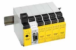
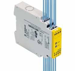
13 Safety Overview of safety technology From the safety sensors of the SMA series to the safety relay family of the 4000 series, and the modular samos safety modules to the samos PRO safety controllers, Wieland Electric offers the right product for your needs. Safe signal acquisition of the SMA series Universal safety relays of the 4000 series safety Modular samos safety modules Compact samos PRO safety controllers 13

14 14


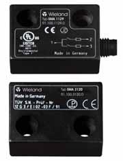
15 SMA Safe signal acquisition The safe sensors of the SMA series ensure effective protection of the people involved in mechanical engineering and system provision. Implementation of standard safety tasks is easy when you have the evaluation devices of the 4000, samos or samos PRO series. SMA series with integrated manipulation protection SMA series The sensors of the SMA series are magnetic safety sensors which are used for the contactless monitoring of protective doors and the detection of safe positions. In addition, they are equipped with integrated manipulation protection. These magnetic safety sensors are an outstanding choice particularly in applications related to position monitoring of mobile protective facilities which have greater tolerances in door guidance or are subjected to the strong vibrations of machine doors. The inductive acquisition of safety-relevant signals helps to avoid dangers. 15


")
16 Product features of the SMA series Use up to category 4 (EN 954-1) High switching interval International protection rating of IP67 Square or round shape Cable connection or M8 screw connection TÜV (technical inspection offices in Germany) certification (pending) 16
17 SMA Safety Sensors SMA series Versatile use The high protection rating of IP67 makes it possible to use these sensors not only in classical machine and plant manufacturing applications but also where a great amount of soiling occurs or strict hygienic regulations must be adhered to (e.g. in the foodstuffs, packaging and pharmaceutical industries). In addition, freedom from mechanical wear, resistance to many chemicals and the lack of sensitivity to shocks of these sensors offer the advantage of long product life. SMA series More flexible and efficient operation With their small and compact design Wieland Electric offers the user the perfect safety sensor for every kind of installation requirement. One round and two square shapes permit optimal integration of the sensors into existing working surroundings. Sensors with cable connection or M8 screw connection are available for quick and easy wiring. 17
 Degree of protection IP67 Technical data SMA")
 8 / 17 mm")


 7 / 20 mm 2 A 18")

18 Safety Sensors SMA series Block-shaped design For rugged operating conditions Manipulation proof Can be used up to category 4 (EN 954-1) Degree of protection IP67 Technical data SMA 0113 SMA 0123 SMA 0119 SMA 0129 Dimensions / mm (L x B x H) 36 x 26 x 13 mm Connection cable, 3m cable, 3m M8 connection M8 connection Actuating distance / (Sao / Sar) 8 / 17 mm Directions of actuation Front - Front / Front - Side / Side - Side Protection degree IP67 Contact type Reed Contact assignment Ö / S S / S Ö / S S / S Switching voltage DC 48 V Switching current 0.2 A Rectangle-shaped design For rugged operating conditions Manipulation proof Can be used up to category 4 (EN 954-1) Degree of protection IP67 Technical data SMA 0213 SMA 0223 SMA 0219 SMA 0229 Dimensions / mm (L x B x H) 88 x 25 x 14 mm Connection cable, 3m cable, 3m M8 connector M8 connector Actuating distance / (Sao / Sar) 7 / 20 mm Directions of actuation Front - Front / Front - Side / Side - Side Protection degree IP67 Contact type Reed Contact assignment Ö / S S / S Ö / S S / S Switching voltage DC 48 V Switching current 0.2 A 18
 M30 x 32 mm Connection cable, 3m cable, 3m M8 connection M8 connection Actuating distance / (Sao / Sar)")


19 Round-shaped design For rugged operating conditions Manipulation proof Can be used up to category 4 (EN 954-1) Degree of protection IP67 SMA series Technical data SMA 0313 SMA 0323 SMA 0319 SMA 0329 Dimensions / mm (Ø x L) M30 x 32 mm Connection cable, 3m cable, 3m M8 connection M8 connection Actuating distance / (Sao / Sar) 7 / 20 mm Directions of actuation Front - Front Protection degree IP67 Contact type Reed Contact assignment Ö / S S / S Ö / S S / S Switching voltage DC 48 V Switching current 0.2 A Type Bauform Kontakt Part no. Std. Pack SMA 0113 Block, with cable Ö/S R SMA 0123 Block, with cable S/S R SMA 0119 Block, with M8 connection Ö/S R SMA 0129 Block, with M8 connection S/S R SMA 4100 Washer R SMA 0213 Rectangle, with cable Ö/S R SMA 0223 Rectangle, with cable S/S R SMA 0219 Rectangle, with M8 connection Ö/S R SMA 0229 Rectangle, with M8 connection S/S R SMA 4200 Washer R SMA 0313 Round, with cable Ö/S R SMA 0323 Round, with cable S/S R SMA 0219 Round, with M8 connection Ö/S R SMA 0329 Round, with M8 connection S/S R SMA 5004 Cable, 5m R SMA 5005 Cable, 10m Ö/S R

20 20


, Performance Level PL e (EN ISO 13849-1) or SIL")

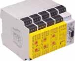
21 S 4000 Universal safety relays 4000 series The safety relays of the 4000 series offer customized solutions for the safety of man and machine. These devices combine excellent technical performance with efficient use in everyday industrial applications. Compact design, flexible use and flexible connection methods are the decisive advantages of these devices. Depending on the application and the selected device, the safety relays can be used up to category 4 (EN 954-1), Performance Level PL e (EN ISO ) or SIL 3 (EN 62061). Versatile application options Emergency stop monitoring Monitoring of protective doors and locking Light curtain monitoring Two-hand relay Monitoring of valves and limit value switches Safe contact expansions 4000 series The simple and safe connection for every situation 21


22 22


23 S 4000 Safe basic devices 4000 series The basic devices are equipped with safe, integrated logic for monitoring safety functions and connections for a startup/re-startup block and monitoring of external actuators. Application areas Emergency stop monitoring Protective door monitoring Monitoring of light curtains and light barriers Two-hand monitoring Monitoring of valves and limit value switches Elevator systems Features Monitored manual start Unmonitored manual start Automatic start 1 or 2-channel activation Safe output contacts (normally open contact) Compact design 3 types of connection 4000 series 23


24 24

25 S 4000 Safe basic devices with time function 4000 series The basic devices with time function are equipped with a safe, integrated logic for monitoring the safety functions and connections for a startup/re-startup block and the monitoring of external actuators. In addition, these devices offer a safe time function for some of the output contacts. The desired triggering or off-delay time can be adjusted flexibly. Application areas Controlled shutdown Monitoring of blocking facilities Safe time relay 4000 series Features Time function off-delay without retriggering Time function off-delay delay with retriggering Time function on-delay Monitored manual start Unmonitored manual start Automatic start 1 or 2-channel activation Safe output contacts (normally open contact) Compact design 3 types of connection 25


26 26

27 S 4000 Contact expansion relay 4000 series Safe contact expansions are used in connection with safe basic devices which have integrated monitoring logic. These can be safety relays with basic function, light curtains or safe controllers, for example. Application areas Emergency stop monitoring Protective door monitoring Light curtain monitoring Monitoring of valves and limit value switches Features 1- or 2-channel activation Fixed off-delay Safe output contacts Compact design 3 types of connection 4000 series Carefully conceived safety solutions for the production plants of the pharmaceutical industry. 27

28 Basic Device SNO 4003K Basic device for single-channel emergency stop and safety gate monitoring Stop category 0 according to EN Applications up to safety category 2 according to EN Safety category of the device: 4 according to EN Manual or automatic start 3 enabling current paths, 1 signaling current path Feedback loop for monitoring external contactors Applications Protection of people and machinery For immediate interruption of the power supply stop category 0 Monitoring of emergency stop applications Monitoring of safety gates Protective measures in sections of the safety system Function The device is a single-channel switching device for emergency stop applications with self-monitoring on each ON-OFF cycle. It complies with EN and is equipped with positively driven relays. The device has two reset inputs Y2 (without reset monitoring) or Y3 (with reset monitoring). The relays K1 and K2 are actuated either after the reset button (on Y1-Y3) has been pressed or automatically (bridge Y1-Y2). They become self-locking through their own contacts, if there is an electrical connection between terminal A1 and the supply voltage (emergency stop button, position switches). After this switch-on phase the enabling current paths are closed and the signaling current path is open. If the electrical connections between terminal A1 and the supply voltage are interrupted, the enabling current paths open and the signaling current path closes. The energized state (self-locking) of the two channels is indicated by a green LED K1, K2. The second green LED indicates that supply voltage has been applied. The set-up of an emergency stop facility after stop category 0 (EN ) is possible. The device corresponds to category 4 for safety-related parts of controls (EN 954-1). Overview of devices / Part numbers Type Rated voltage Terminals Part no. Std. Pack SNO 4003K AC/DC 24 V Hz Screw terminals, fixed R AC V Hz Screw terminals, fixed R AC 230 V Hz Screw terminals, fixed R SNO 4003K-A AC/DC 24 V Hz Screw terminals, pluggable R AC V Hz Screw terminals, pluggable R AC 230 V Hz Screw terminals, pluggable R SNO 4003K-C AC/DC 24 V Hz Cage clamp, pluggable R SNO 4003K / K-A AC / DC 24 V SNO 4003K / K-A AC V / AC 230 V 28
29 Technical data SNO 4003K Function according to EN Emergency stop relay Function display 2 LEDs green Function diagram FD W, FD W Power supply circuit Devices with rated voltage AC/DC 24 V min. typ. max. Operating voltage range AC/DC 20.4 V AC/DC 24 V AC/DC 26.4 V Residual ripple 2.4 V SS Rated consumption DC W 1.6 W Rated consumption AC W/3.2 VA 2.2 W/3.9 VA Rated frequency AC 50 Hz - 60 Hz Input inrush current (A1) A Rated short-circuit current ma - Response time / recovery time 2 s /3 s Fuse for control circuit supply PTC thermistor Electrical isolation supply circuit control circuit no Devices with rated voltage AC V/AC 230 V Operating voltage range U N = AC V AC 93.5 V AC V AC 132 V Operating voltage range U N = AC 230 V AC 195 V AC 230 V AC 253 V Rated consumption W/2.3 VA 2.4 W/2.8 VA Rated frequency AC 50 Hz - 60 Hz Wire length to the safe transducer (wires installed in parallel; see the notes on the wire lengths) Fuse for control circuit supply Short-circuit proof transformer Electrical isolation supply circuit control circuit yes Control circuit Conductor resistance in Y1-Y2 or Y1-Y3 (at UN dep. on supply voltage) Ω Rated output voltage to the supply of input Y2 - DC 24 V - Open circuit voltage - - DC 40 V Rated current / peak current (inputs Y2, Y3) ma/1500 ma Release time t R (K1, K2) - 60 ms 80 ms Response time ta 1 (devices with rated current AC V/AC 230 V) ms 300 ms Response time ta 1 (devices with rated voltage AC/DC 24 V) - 40 ms 60 ms Response time ta2-40 ms 60 ms Minimum ON time t M1 (Y2) t A1 - - Minimum ON time t M2 (Y3) t A2 - - Recovery time t W ms Stand-by time t B ms Output circuit Contact assignment 3 enabling current paths with positively driven contacts (NO), 1 signaling current path (NC) Rated switching voltage U n AC/DC 230 V Max. continuous current I n per current path, NO / NC 8 A/5 A Max. total current of all current paths for devices with rated voltage AC/DC 24 V 12 A Max. total current of all current paths 8 A for devices with rated voltage AC V/AC 230 V Application category according to EN h -1 AC-15: U e 230 V, I e 4 A / DC-13: U e 24 V, I e 4 A 3600 h -1 AC-15: U e 230 V, I e 3 A / DC-13: U e 24 V, I e 2.5 A Short-circuit protection max. fuse 6 A class gg or circuit breaker with trigger characteristic B or C Short-circuit protection, fuse max. 8 A Mechanical life 10x 10 6 switching cycles General data Creepage distances and clearances between the circuits according to EN depending on device version; see Electrical isolation, supply circuit Overvoltage category III Rated impulse voltage 4 kv Rated voltage AC 300 V Test AC voltage 2 kv Degree of pollution of the device: inside / outside 2/3 Protection degree according to DIN EN (housing / terminals) IP 40/IP 20 Ambient temperature / storage temperature C/ C Dimension diagram K 4-1 (screw terminals / K 4-2 (pluggable terminals) Wire ranges fine-stranded / solid 2x mm 2 /1x mm 2 or fine-stranded with ferrules 1x mm 2 /2x mm 2 Permissible torque Nm Weight for devices with rated voltage AC/DC 24 V 0.20 kg Weight for devices with rated voltage AC V/AC 230 V 0.25 kg Approvals series

30 Basic Device SNO 4062K /SNO 4062KM Basic device for single-channel or two-channel emergency stop, safety gate, safety mat/strip and light curtain application Stop category 0 according to EN Applications up to safety category 4 according to EN Safety category of the devices: 4 according to EN Reset button monitoring Single-channel and two-channel control Cross monitoring 2 enabling current paths, 1 signaling current path Applications Monitoring of separating protective equipment Monitoring of rollup doors For processing signals from the output signal switching devices (OSSD) of a light curtain according to DIN EN For connecting to a safety mat according to DIN EN (SNO 4062KM) Function SNO 4062K The device is a two-channel switching device for emergency stop applications with self-monitoring on each ON-OFF cycle. It complies with EN and is equipped with positively driven relays. Basic function: With supply voltage applied to terminals A1/A2 and the safety inputs closed, operating of the reset button closes the enabling current paths (manual start). When the safety inputs are opened/de-energized the enabling current paths will open. Operating modes / system functions Single or two-channel control With single-channel control both safety channels CH1 and CH2 are connected in parallel; with two-channel control they are switched separately. Without cross monitoring Both safety channels are switched to the positive potential (S12 and S31 to S11). With cross monitoring Safety channel CH1 is switched to the positive potential (S11 to S12), and safety channel CH2 to the negative potential (S21 to S22). Manual start When the safety inputs are closed, a button is used to open reset input S34 (triggering with falling edge) or to close reset input S35 (triggering with rising edge). Automatic start Reset input S35 is connected to S33. The device starts with the rising edge of the signal on safety input S12. Start inhibit After supply voltage has been applied and the safety inputs closed, the enabling paths will not close. Starting is only possible after the reset button has been operated. For start inhibit the reset inputs have to be controlled with the button, as with manual start mode. Restart inhibit No restart after the safety inputs have been opened and closed. Restarting is only possible after the reset button has been operated. For restart inhibit the reset inputs have to be activated with the button, as in manual start mode. Semiconductor compatible OSSD (output signal switching devices) signals from a light curtain or other safety sensors with semiconductor outputs can be processed. Test pulses <t TP do not influence the device functions. Test pulses >t TP can lock the device. Synchrocheck With two-channel control both safety channels are monitored against one another with the synchronous time t S. Safety channel CH1 must close before CH2 and bridge S33/S35 must be connected. If CH2 closes before CH1, the synchronous time t S = and synchrocheck is switched off. SNO 4062KM The function of this device corresponds to that of the SNO 4062K without synchrocheck. The device is suitable for connecting to light curtains for Si category 4 and connecting to short-circuit forming 4-wire safety mats, switching strips or switching edges (without monitoring resistance). Safety mats The device must be operated with two channels and cross monitoring. If there is resistance < 50 Ω / channel and a short circuit between the channels (S11/S12 and S21/S22) the enabling paths open and the SUPPLY LED flashes. Light curtain for Si category 4 The device will be operated with two channels and without cross monitoring, if the light curtain connected to the OSSD detects a shunt fault on its own. Input debouncing Input debouncing prevents fast consecutive switching of the enabling current paths when the safety inputs are opened for less than t ASP. Safety inputs opened for longer than t ASP lead to opening of the enabling current paths after t R. Restarting is blocked for time t SP. For applications with tactile operating modes (rapid ON-OFF cycles, for example with manual supply) we recommend the use of SNO 4062KM. SNO 4062K /K-A /KM /KM-A 30
31 Overview of devices / Part numbers Type Rated voltage Terminals Part no. Std. Pack SNO 4062K AC/DC 24 V Hz Screw terminals, fixed R SNO 4062K-A AC/DC 24 V Hz Screw terminals, pluggable R SNO 4062KM AC/DC 24 V Hz Screw terminals, fixed R SNO 4062KM-A AC/DC 24 V Hz Screw terminals, pluggable R SNO 4062K-C AC/DC 24 V Hz Cage clamp, pluggable R Technical data SNO 4062K SNO 4062KM Function according to EN Emergency stop relay Function display 3 LEDs, green Function diagram FD W, FD W Power supply circuit Rated voltage U N AC/DC 24 V Rated consumption DC 2.0 W 2.1 W Rated consumption AC 2.4 W/4,4 VA 2.5 W/4.6 VA Residual ripple 2.4 V ss Rated frequency Hz Operating voltage range x U N Fuse for control circuit supply Short-circuit resistant (PTC thermistor) Short-circuit resistant (electronic fuse) Control circuit Rated output voltage (S11, S33 to S21) DC 22 V Output current / peak current 100 ma/2000 ma 100 ma/300 ma Input voltage range high DC 17.4 V DC 26.4 V low DC 3.0 V DC +5.0 V Rated current / peak current (S12, S31/S22) 40 ma/100 ma Rated current / peak current (S34, S35) 5 ma/50 ma Permissible test pulse time t TP / test frequency 1000 μs/ 10 s -1 Response time t A1 (S34) 20 ms 40 ms Response time t A2 (S35) 200 ms 500 ms 20 ms 80 ms Minimum ON time tm (S34, S35) > 50 ms Locking time t SP 70 ms 130 ms Response time of the lock t ASP > 7 ms Recovery time t W 40 ms 150 ms Release time t R (K1, K2) < 25 ms Synchronous monitoring time t S ca. 200 ms - Max. resistance for short-circuit forming safety mats including connection cables 50 Ω Line resistance 70 Ω Output circuit Enabling paths Contact assignment 2 NO contacts, positively driven Rated switching voltage U n AC 240 V/DC 300 V Max. continuous current I n per contact 6 A Max. total current of all current paths 12 A Application category according to EN h -1 AC-15: U e 230 V AC, I e 4 A / DC-13: U e 24 V DC, I e 4 A 3600 h -1 AC-15: U e 230 V AC, I e 3 A / DC-13: U e 24 V DC, I e 2.5 A Mechanical life 10x 10 6 switching cycles Signaling paths Contact assignment 1 NC contact, parallel, positively driven Rated switching voltage U n AC 240 V/DC 300 V Max. continuous current I n per contact 6 A Application category according to EN h -1 AC-15: U e 230 V AC, I e 4 A / DC-13: U e 24 V DC, I e 4 A 3600 h -1 AC-15: U e 230 V AC, I e 3 A / DC-13: U e 24 V DC, I e 2.5 A Short-circuit protection, max. fuse insert 6 A class gg or circuit breaker with trigger characteristic B or C Mechanical life 10x 10 6 switching cycles General data Creepage distances and clearances between the circuits according to EN Rated impulse voltage 4 kv Overvoltage category III Degree of pollution of the device: inside / outside 2/3 Rated voltage AC 300 V Test voltage U eff 50 Hz 2 kv Protection degree according to DIN EN (housing / terminals) IP 40/IP 20 Ambient temperature / storage temperature C/ C Dimension diagram K 4-1 (screw terminals / K 4-2 (pluggable terminals) Rated cross sections fine-stranded/solid 2x mm 2 /1x mm 2 or fine-stranded with ferrules 1x mm 2 /2x mm 2 Permissible tightening torque Nm Weight 0.21 kg Approvals series

32 Basic Device SNO 4063K /SNO 4063KM Basic devices for single-channel or two-channel emergency stop, safety gate, safety mat/strip and light curtain monitoring Stop category 0 according to EN Applications up to safety category 4 according to EN Safety category of the devices: 4 according to EN Manual or automatic start Cross monitoring Single-channel and two-channel control 3 enabling current paths (NO contact, positively driven); feedback loop for monitoring external contactors Supply voltage reset with SNO 4063KR (without start inhibit) Applications Emergency stop, safety gate, safety mat and light curtain applications For processing signals from the output signal switching devices (OSSD) of a light curtain according to DIN EN For connecting to a safety mat according to DIN EN Function SNO 4063K The device is a two-channel switching device for emergency stop applications with self-monitoring on each ON-OFF cycle. It complies with EN and is equipped with positively driven relays. Basic function After supply voltage has been applied to terminals A1/A2 and the safety inputs closed, operating of the reset button closes the enabling current paths (manual start). When the safety inputs are opened/de-energized the enabling current paths will open. Operating modes / system functions Single or two-channel control With single-channel control both safety channels CH1 and CH2 are connected in parallel; with two-channel control they are switched separately. Without cross monitoring Both safety channels are switched to the positive potential (S12 and S31 to S11). With cross monitoring Safety channel CH1 is switched to the positive potential (S11 to S12), and safety channel CH2 to the negative potential (S21 to S22). Manual start When the safety inputs are closed, a button is used to open reset input S34 (triggering with falling edge) or to close reset input S35 (triggering with rising edge). Automatic start Reset input S35 is connected to S33. The device starts with the rising edge of the signal on safety input S12. Start inhibit After supply voltage has been applied and the safety inputs closed, the enabling paths will not close. Starting is only possible after the reset button has been operated. For start inhibit the reset inputs have to be controlled with the button, as with manual start mode. Restart inhibit No restart after the safety inputs have been opened and closed. Restarting is only possible after the reset button has been operated. For restart inhibit the reset inputs have to be activated with the button, as in manual start mode. Semiconductor compatible OSSD (output signal switching devices) signals from a light curtain or other safety sensors with semiconductor outputs can be processed. Test pulses <t TP do not influence the device functions. Test pulses >t TP can lock the device. Synchrocheck With two-channel control both safety channels are monitored against one another with the synchronous time t S. Safety channel CH1 must close before CH2 and bridge S33/S35 must be connected. If CH2 closes before CH1, the synchronous time is t S =. NO 4063KM The function of this device corresponds to that of the SNO 4063K without synchrocheck. The device is suitable for connecting to light curtains for Si category 4 and to short-circuit forming 4-wire safety mats, switching strips or switching edges (without monitoring resistance). Safety mats The device must be operated with two channels and cross monitoring. If there is resistance < 50 Ω / channel and a short circuit between the channels (S11/S12 and S21/S22) the enabling paths open and the SUPPLY LED flashes. Light curtain for Si category 4 The device will be operated with two channels and without cross monitoring, if the light curtain connected to the OSSD detects a shunt fault on its own. Input debouncing Input debouncing prevents fast consecutive switching of the enabling current paths when the safety inputs are opened for less than t ASP. Safety inputs opened for longer than t ASP lead to opening of the enabling current paths after t R. Restarting is blocked for time t SP. For applications with tactile operating modes (rapid ON-OFF cycles, for example at manual supply) we recommend the use of SNO 4063KM. SNO 4063K / KM / K-A / KM-A AC / DC 24 V SNO 4063K / K-A AC V / AC 230 V 32
33 Overview of devices / Part numbers Type Rated voltage Terminals Part no. Std. Pack SNO 4063K DC 12 V Screw terminals, fixed R AC/DC 24 V Hz Screw terminals, fixed R AC V Hz Screw terminals, fixed R AC 230 V Hz Screw terminals, fixed R SNO 4063K-A DC 12 V Screw terminals, pluggable R AC/DC 24 V Hz Screw terminals, pluggable R AC V Hz Screw terminals, pluggable R AC 230 V Hz Screw terminals, pluggable R SNO 4063KM AC/DC 24 V Hz Screw terminals, fixed R SNO 4063KM-A AC/DC 24 V Hz Screw terminals, pluggable R SNO 4063KR DC 12 V Screw terminals, fixed R AC/DC 24 V Hz Screw terminals, fixed R AC V Hz Screw terminals, fixed R AC 230 V Hz Screw terminals, fixed R SNO 4063KR-A DC 12 V Screw terminals, pluggable R AC/DC 24 V Hz Screw terminals, pluggable R AC V Hz Screw terminals, pluggable R AC 230 V Hz Screw terminals, pluggable R SNO 4063K-C AC/DC 24 V Cage clamp, pluggable R Technical data SNO 4063K SNO 4063KM Function according to EN Emergency stop relay Function display 3 LEDs, green Function diagram FD W, FD W, FD W Power supply circuit Rated voltage U N DC 12 V, AC/DC 24 V, AC V, AC 230 V AC/DC 24 V Rated consumption DC 2.0 W 2.1 W Rated consumption AC 2.4 W/4.4 VA 2.5 W/4.6 VA Residual ripple 2.4 V ss Rated frequency Hz Operating voltage range x U N Fuse for control circuit supply short-circuit resistant Control circuit Outputs (S11, S21) Rated output voltage (S11 to S21) DC 22 V Open circuit voltage (only AC devices) < 40 V Output current 100 ma Short circuit protection / current limitation yes/ yes/250 ma Inputs (S12/S33, S31/S22, S34, S35) Input voltage range (only for DC devices) DC 17.4 V bis DC 26.4 V Rated current / peak current (safety inputs S12/S33, S31/S22) 40 ma/100 ma Rated current / peak current (reset inputs S34, S35) 5 ma/50 ma Times Permissible test pulse time t TP /test frequency 1000 μs/ 10 s -1 Response time t A1 (reset input S34) 20 ms 40 ms Response time t A2 (reset input S35) 200 ms 600 ms 20 ms 80 ms Minimum ON time t M (reset inputs S34, S35) > 80 ms Recovery time t W 100 ms Release time t R (K1, K2) with emergency stop < 25 ms Synchronous time t S ca. 200 ms Output circuit Enabling paths Contact assignment 3 NO contacts, positively driven Rated switching voltage U n AC 230 V/DC 300 V Max. continuous current I n per contact 6 A Max. total current of all current paths DC 12 V, AC/DC 24 V 12 A AC V, AC 230 V 8 A General data Creepage distances and clearances between the circuits according to EN Protection degree according to DIN EN (housing / terminals) IP 40/IP 20 Ambient temperature / storage temperature C/ C Dimension diagram K 4-1 (screw terminals / K 4-2 (pluggable terminals) Wire ranges fine-stranded / solid 2x mm 2 /1x mm 2 or fine-stranded with ferrules 1x mm 2 /2x mm 2 Permissible torque Nm for UL and CSA applications Wire ranges AWG only use Cu wires Max. tightening torques 0.79 in-lbs Weight 0.21 kg (DC device) / 0.25 kg (AC device) Approvals series
 Compact design Applications Protection of people and machinery Control of power contactors Emergency stop devices Monitoring of")
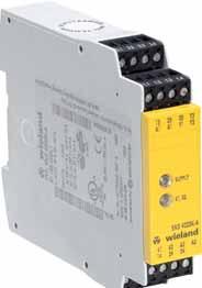
34 Basic Device SNO 2004K Basic device for emergency stop and safety gate applications Stop category 0 according to EN Applications up to safety category 2 according to EN Single-channel control 2 enabling current paths Check of external contactors (EDM) Compact design Applications Protection of people and machinery Control of power contactors Emergency stop devices Monitoring of safety gate Function After the operating voltage (L+/L1) is applied via a not actuated emergency stop button or safety gate contact on A1 and A2, the device can be switched on via a Y1/Y2-connected reset button. When the device is on, the internal relays K1 and K2 are energized and the enabling current paths 13/14 and 23/24 are closed. When the emergency stop button or the safety gate contact is actuated, the current supply of the internal relays is interrupted and the enable current paths are opened. SNO 2004K Notes The control category as per EN depends on, among others, the external wiring, the choice of command devices and their arrangement on the machine. The devices must be installed in a control cabinet with a degree of protection of at least IP54. The expansion devices of the SNE series or external contactors with positively driven contacts can be used to duplicate the enable current paths. 34
35 Overview of devices / Part numbers Type Rated voltage Dimension diagram Terminals Part no. Std. Pack SNO 2004K AC/DC 24 V K3-2 Screw terminals, fixed R Technical data SNO 2004K Function according to EN Emergency stop relay Function display 2 LEDs, green Function diagram FD Power supply circuit Rated voltage AC / DC 24 V Rated consumption at 50 Hz and U N (AC) 1 VA Rated consumption at U N (DC) 1 W Residual ripple U ss 2.4 V Rated frequency Hz Operating voltage range x U N Control circuit only for supplying the control inputs Electrical isolation between A1 and A2 no Line resistance (control inputs) < 70 Ω Rated output voltage Y1 DC 24 V Rated current / crest current entrance Y2 100 ma / 100 ma Response time 20 ms Release time t R 50 ms Min. ON time t M 30 ms Output circuit Contact assignment 2 enabling current paths (NO contact) Contact type positively driven Contact material Ag alloy Rated operating voltage U n AC / DC 230 V Max. continuous current I n per contact 6 A Max. total current of all current paths 8 A Application category according to EN AC-15: Ue 230 V AC, Ie 3 A DC-13: Ue 24 V DC, Ie 3 A Short-circuit protection, max. fuse insert 6 A gg Mechanical life 10 7 switching cycles General data Creepage distances and clearances between the circuits according to EN Rated impulse voltage 4 kv Overvoltage category III Degree of pollution 3 outside, 2 inside Rated voltage 300 V AC Test voltage U eff 50 Hz 2 kv Protection degree according to DIN EN (housing / terminals IP 40 / IP 20 Ambient temperature, operating range C Screw terminals Rated cross sections fine-stranded/solid 2 x mm 2 / 1 x mm 2 or fine-stranded with ferrules 2 x mm 2 / 1 x mm 2 Permissible tightening torque Nm Weight 0.2 kg Accessories - Approvals 4000 series 35


36 Basic Device SNO 2005 Basic device for emergency stop and safety gate applications Stop category 0 according to EN Applications up to safety category 4 according to EN Safety category of the device: 4 according to EN Single-channel or two-channel control through contacts or semiconductors Cross monitoring Reset button monitoring 3 enabling current paths, 1 signaling current path Applications Protection of people and machinery Monitoring of sliding safety gates Protective measures in sections of the safety system In association with automation systems Function With supply voltage applied to terminals A1/A2 and the emergency stop button not operated, the relay K1 is activated by pressing the reset button. The control logic of relay K1 controls relays K2 and K3. which become self-locking through their own contacts. After this switch-on phase the three enabling current paths defined for the output are closed (terminals 13/14, 23/24, 33/34) and the signaling current path opened (terminals 41/42). This is indicated by 3 LEDs that are assigned to safety channels K2, K3 as well as to the supply voltage. If the emergency stop button is activated, the current supplies for the relays K2 and K3 are interrupted. The enabling current paths on the output are opened or the signaling current path is closed. With a two-channel wiring of the emergency stop button and cross-monitoring wiring of the emergency stop button circuit, additional errors such as shunt fault or ground fault can be detected. An electronic fuse protects the emergency stop relay against damage. After the cause of the malfunction has been removed, the device is operational again after approx. 2 s. Reset button monitoring The emergency stop relay is equipped with/without reset button monitoring. During reset button monitoring (terminal Y13) the device is only enabled with the falling edge of the reset button. This feature only allows a static operation of the device. For starting the reset button must always be pressed and released. It is not possible to perform an automatic start by jumpering the reset button (see function diagram FD W1). Operation without reset button monitoring (terminal Y14) is suitable for dynamic operation (automatic start). The reset button can be jumpered. This function is required for safety gate applications (see function diagram FD W1). Overview of devices / Part numbers Type Rated voltage Terminals Part no. Std. Pack SNO 2005 DC 24 V Screw terminals, fixed R AC 24 V Hz Screw terminals, fixed R AC 115 V Hz Screw terminals, fixed R AC 120 V Hz Screw terminals, fixed R AC 230 V Hz Screw terminals, fixed R
37 Technical data SNO 2005 Function according to EN Emergency stop relay Function display 3 LEDs green Function diagram FD x W1 Power supply circuit Rated voltage U N AC 24 V 115 V 120 V 230 V Rated voltage U N DC 24 V Rated consumption at 50 Hz and U N (AC) 3.2 VA 3.2 VA 3.2 VA 3.2 VA Rated consumption at 50 Hz and U N (AC) 2.5 W 2.5 W 2.5 W 2.5 W Rated consumption at U N (DC) 1.0 W Residual ripple 2.4 V ss Rated frequency Hz Operating voltage range 0,8 1,1x UN Control circuit only for supplying the control inputs Electrical isolation between A1, A2 and Y11, Y21, PE yes for AC devices Line resistance (control inputs) 70 Ω Rated output voltage DC 24 V Open-circuit voltage (AC devices) DC 40 V Nominal current 40 ma Short-circuit current I K max ma Fuse AC: short-circuit resistant transformer DC: PTC thermistor Response time (PTC) 3 s Recovery time (PTC) 2 s Control input Y12, Y13, Y14, Y31: Rated current input Y13, Y14 40 ma Rated current input Y12, Y31 15 ma Response time t A1 K2, K3 (with reset button monitoring) on Y ms Response time t A2 K2, K3 (without reset button monitoring) on Y ms Release time at emergency stop 50 ms Release time t R1 at supply voltage interruption 100 ms Synchronous time t S 500 ms 4000 series Stand-by time t B 100 ms (only for AC devices) Recovery time t W (without reset button monitoring) 500 ms Output circuit Contact assignment 3 enabling current paths (NO contact) 1 signaling current path (NC contact) Contact type positively driven Contact material Ag alloy, gold-plated Rated operating voltage U n 230/230 V AC/DC Max. continuous current I n per contact 6 A Max. total current of all current paths 18 A Application category according to EN AC-15: Ue 230 V AC, Ie 4 A (3600 switching cycles/h) DC-13: Ue 24 V DC, Ie 6 A (360 switching cycles/h) DC-13: Ue 24 V DC, Ie 3 A (3600 switching cycles/h) Short-circuit protection, max. fuse insert 6 A class gg or circuit breaker with trigger characteristic B or C Permissible switching frequency 3600 switching cycles/h Mechanical life 10x106 switching cycles General data Creepage distances and clearances between the circuits according to EN Rated impulse voltage 4 kv Overvoltage category III Degree of pollution 3 outside, 2 inside Rated voltage 300 V AC Test voltage U eff 50 Hz 2 kv Protection degree according to DIN EN (housing / terminals) IP 40/IP 20 Ambient temperature, operating range C Dimension diagram S 7-4 Rated cross sections fine-stranded/solid 2x mm 2 /2x mm 2 or fine-stranded with ferrules 1 or 2x mm 2 Permissible tightening torque Nm Weight 0.36 kg (AC device), 0.3 kg (DC device) Accessories Holder Z 31-1 (R ) Approvals 37
38 Basic Device SNA 4043K/KM, SNA 4044K/KM, SNA 4063K/KM, SNA 4064K/KM Emergency stop and safety gate monitor The safety switching devices of our SNA product line are used to monitor safety sensors (emergency stop buttons, safety gate switches, etc.), feature a large number of safety switching contacts (3 NO contacts/1 NC contact or 4 NO contacts) with a total width of only 22.5 mm at a constant current of up to 8 A. They can be implemented in the extended temperature range up to 65 C. Applications These devices can be implemented e.g. in mechanical engineering applications, in the packaging-, the plastics processing industry, the wood and building materials processing industries and the plant engineering sector. They can also be used to monitor robots and can be further applied in transport and building machinery, in combustion plants and in elevator systems. They are applicable up to category 4 according to EN or to SILCL 3 respectively according to EN Function Manual reset with monitoring Automatic reset Supply voltage ranging from 24 V AC/DC to 230 V AC With or without cross monitoring Single-channel or two-channel emergency stop monitoring Single-channel or two-channel safety gate monitoring (e.g. with mechanical or magnetic safety switches) Safe semiconductor outputs (e.g. of safety controls or safety light curtains) can be implemented as safe relay outputs Technical data SNA 4043K/KM SNA 4044K/KM SNA 4063K/KM SNA 4064K/KM Function according to EN Emergency stop relay Emergency stop relay Contact assignment 3 enabling current 4 enabling current paths 3 enabling current paths (NO contact) paths (NO contact) 4 enabling current paths 38 Power supply circuit 1 signaling current path (NC contact) (normally open contact) 1 signaling current path (NC contact) (normally open contact) Rated voltage AC/DC 24 V / AC V / AC V / AC 230 V AC/DC 24 V / AC V / AC V / AC 230 V Operating voltage range x U N x U N Control circuit Electrical isolation between A1, A2 and control circuits AC devices AC devices Rated current/peak current input S12, S52, S22 25 ma / 100 ma 25 ma / 100 ma Rated current/peak current input S34 5 ma / 100 ma 5 ma / 100 ma Function display 3 LEDs, green 3 LEDs, green Output circuit Release time t R 10 ms 10 ms Contact type positively driven positively driven Rated switching voltage U n AC 230 V AC 230 V Max. continuous current In per current path 8 A / 6 A 8 A / 6 A (AC/DC 24 V device / AC devices) Max. total current of all current paths 12 A / 8 A 12 A / 8 A (AC/DC 24 V device / AC device) Application category according AC-15: U e 230 V AC, I e 4 A (360 h -1 ) AC-15: U e 230 V AC, I e 4 A (360 h -1 ) to EN DC-13: U e 24 V DC, I e 4 A (360 h -1 ) DC-13: U e 24 V DC, I e 4 A (360 h -1 ) General data Creepage distances and clearances between the circuits according to EN according to EN Protection degree according to DIN EN (housing / terminals) IP 40 / IP 20 IP 40 / IP 20 Ambient temperature, operating range C C Standards IEC 61508, EN 954-1, ISO , EN 81-1, EN IEC 61508, EN 954-1, ISO , EN 81-1, EN Approvals

39 SNA 4043K/KM SNA 4044K/KM Type Rated voltage Terminals Part no. Std. Pack SNA 4043K AC/DC 24 V Screw terminals, fixed R SNA 4043K AC V Screw terminals, fixed R SNA 4043K AC V Screw terminals, fixed R SNA 4043K AC 230 V Screw terminals, fixed R SNA 4043K-A AC/DC 24 V Screw terminals, pluggable R SNA 4043K-A AC V Screw terminals, pluggable R SNA 4043K-A AC V Screw terminals, pluggable R SNA 4043K-A AC 230 V Screw terminals, pluggable R SNA 4043K-C AC/DC 24 V Cage clamp, pluggable R SNA 4043KM AC/DC 24 V Screw terminals, fixed R SNA 4043KM-A AC/DC 24 V Screw terminals, pluggable R SNA 4043KM-C AC/DC 24 V Cage clamp, pluggable R SNA 4044K AC/DC 24 V Screw terminals, fixed R SNA 4044K AC V Screw terminals, fixed R SNA 4044K AC V Screw terminals, fixed R SNA 4044K AC 230 V Screw terminals, fixed R SNA 4044K-A AC/DC 24 V Screw terminals, pluggable R SNA 4044K-A AC V Screw terminals, pluggable R SNA 4044K-A AC V Screw terminals, pluggable R SNA 4044K-A AC 230 V Screw terminals, pluggable R SNA 4044K-C AC/DC 24 V Cage clamp, pluggable R SNA 4044KM AC/DC 24 V Screw terminals, fixed R SNA 4044KM-A AC/DC 24 V Screw terminals, pluggable R SNA 4044KM-C AC/DC 24 V Cage clamp, pluggable R SNA 4063K AC/DC 24 V Screw terminals, fixed R SNA 4063K AC V Screw terminals, fixed R SNA 4063K AC V Screw terminals, fixed R SNA 4063K AC 230 V Screw terminals, fixed R SNA 4063K-A AC/DC 24 V Screw terminals, pluggable R SNA 4063K-A AC V Screw terminals, pluggable R SNA 4063K-A AC V Screw terminals, pluggable R SNA 4063K-A AC 230 V Screw terminals, pluggable R SNA 4063K-C AC/DC 24 V Cage clamp, pluggable R SNA 4063KM AC/DC 24 V Screw terminals, fixed R SNA 4063KM-A AC/DC 24 V Screw terminals, pluggable R SNA 4063KM-C AC/DC 24 V Cage clamp, pluggable R SNA 4064K AC/DC 24 V Screw terminals, fixed R SNA 4064K AC V Screw terminals, fixed R SNA 4064K AC V Screw terminals, fixed R SNA 4064K AC 230 V Screw terminals, fixed R SNA 4064K-A AC/DC 24 V Screw terminals, pluggable R SNA 4064K-A AC V Screw terminals, pluggable R SNA 4064K-A AC V Screw terminals, pluggable R SNA 4064K-A AC 230 V Screw terminals, pluggable R SNA 4064K-C AC/DC 24 V Cage clamp, pluggable R SNA 4064KM AC/DC 24 V Screw terminals, fixed R SNA 4064KM-A AC/DC 24 V Screw terminals, pluggable R SNA 4064KM-C AC/DC 24 V Cage clamp, pluggable R series 39
40 Basic Device SNL 4062K Light barrier evaluation and test device Stop category 0 according to EN Applications up to safety category 3 according to EN Safety category of the device: 3 according to EN For electrosensitive protective equipment type 2 according to EN Cyclic tests, override function, reset button monitoring, cross monitoring 2 input channels, control through single-channel or two-channel contacts or semiconductors 2 enabling current paths, 1 signaling current path Applications Monitoring of one-way safety light barriers with test input Emergency stop and safety gate applications Protection of people, material and machinery in a transfer area; access protection Function The light barrier evaluation and test device SNL 4062K operates as the interface between optoelectronic equipment according to EN /-2 type 2 and the machine control. The device is used to protect hazardous areas around powered machinery and provides the following integrated features: start disable, restart disable, override, self test, cyclic test, time monitoring, feedback loop and output circuit via positively driven relays. With supply voltage applied to terminals A1/A2 a self test is performed after which the device is ready to operate. If the self test fails, the program is aborted and a restart is necessary. Further activation of the device depends on the results of the self test, the selected operating mode and the status of the external connected circuit (see Function flowchart ). Compliance of the light barrier signals at inputs Y12 and Y22 with those at outputs Y41 and Y42 is checked and displayed by the READY LED. Depending on the selected function and with the light barrier inputs actuated, the enabling current paths of the SNL 4062K either switch into the ON position (operation without start inhibit), or they remain in the OFF position until the reset key is pressed and released again (restart inhibit). Two NO contacts and one signaling current path (NC contact) are available as enabling current paths. The state of the outputs is displayed by the multicolored OSSD LED. green light = enabling current paths in ON position red light = enabling current paths in OFF position The enabling current paths are switched off when one of the following events occurs: 1. The light barrier inputs are de-energized in case they have been previously enabled. 2. The override input is also de-energized during the override operation in case the light barrier inputs were previously disabled. 3. A fault has been detected during the cyclic self test. 4. If both light barrier inputs are energized during the override operation. Override: When the safety device is jumpered, it is not guaranteed that relays K1 and K2 (OSSD) are switched off as long as the override signal is applied (operating mode: static input signal). After activation of the safety function the SNL 4062K will switch into the operational state All device-internal tests and starting cycle tests are performed again. If no errors are found during the starting cycle tests, operation can be continued. The device is delivered with jumpered terminals. Operating modes Selectable function features: Test pulse direction (pos./neg. pulse) Restart inhibit (ON/OFF) Override (static/dynamic) The operating mode can be pre-set on the rear of the housing using the DIP switches (see Operating modes ). These switches are no longer accessible when the device is mounted on a DIN rail. SNL 4062K-A The functions of this device correspond to those of the SNL 4062K. Devices with the -A identification in their type designation are equipped with four removable pluggable terminals (see the K4-2 dimension diagram). This feature allows a quick installing/removing operation. The terminal locations are coded and not interchangeable. Pluggable terminal Device connection Pluggable terminal Device connection The start inhibit prevents the device from switching into the ON position when electrical power is applied, or interrupted and applied again. The restart inhibit prevents the enabling current paths from switching on again without manual operation after switch-off, provided that the enabling conditions have been fulfilled. Device connection Pluggable terminal Device connection Pluggable terminal 40
41 Overview of devices / Part numbers Type Rated voltage Terminals Part no. Std. Pack SNL 4062K DC 24 V Screw terminals, fixed R SNL 4062K-A DC 24 V Screw terminals, pluggable R Technical data SNL 4062K Function according to EN Light barrier evaluation device Function display 3 LEDs green, 1 LED yellow (MUTING) Function diagram FD and -2 W1 Power supply circuit Rated voltage U N DC Rated consumption at U N (DC) 1.8 W Residual ripple 2.4 V ss Operating voltage range x U N Control circuit Electrical isolation between A1, A2 and X1, X2, Y12, Y22, Y41, Y42, S33, S34 no Fuse / response time / recovery time PTC themistor / 2 s/3 s Control input S34 DC 24 V Rated current input S34 10 ma Min./max. ON time RESET t RE 50 ms/3000 ms Self test t 1 /test driver t ms/10 ms Input circuit Number of inputs 2 High/low level input Y12, Y22 DC V/ DC 8 V Rated current input Y12, Y ma Test signal Y41, Y42 neg. pulse DC 24 V Rated current test signal Y41, Y ma Start test t ms Max. total test time t 1 to t ms Response time t A (with restart inhibit) 50 ms Release time t R 20 ms Max. test pulse time t P 80 ms Max. test monitoring time t Ü 150 ms Test cycle time 6 s Override circuit Number of inputs 1 High/low level input / rated current X1 DC 15 to 26.4 V/ DC 8 V/10 ma Static control; min. switch-on time, static 66 ms Input frequency range, dyn Hz Pulse duty factor 1:1 Check at override input t ms Output circuit Contact assignment 2 enabling current paths (NO), 1 signaling current path (NC), positively driven contacts Rated switching voltage U n AC/DC 230 V Max. continuous current I n per contact 6 A Max. total current of all current paths 12 A Application category according to EN Short-circuit protection max. fuse Permissible switching frequency Mechanical life 3600 switching cycles/h AC-15: U e 230 V AC, I e 6 A / DC-13: U e 24 V DC, I e 3 A 360 switching cycles/h DC-13: U e 24 V DC, I e 6 A 6 A class gg or circuit breaker with trigger characteristic B or C 3600 switching cycles/h 30x10 6 switching cycles General data Creepage distances and clearances between the circuits according to EN Rated impulse voltage 4 kv Overvoltage category III Degree of pollution 3 outside, 2 inside Rated voltage AC 300 V Test voltage U eff 50 Hz 2 kv Protection degree according to DIN EN (housing / terminals) IP 40/IP 20 Ambient temperature, operating range C Dimension diagram K 4-1 (screw terminals / K 4-2 (pluggable terminals) Wire ranges fine-stranded / solid 2x mm 2 /1x mm 2 or fine-stranded with ferrules 1x mm 2 /2x mm 2 Permissible torque Nm Weight 0.17 kg Accessories for UL and CSA applications Wire ranges AWG only use Cu wires Max. tightening torques 5.25 in-lbs Approvals series
42 Basic Device SNT 4M63K/SNT 4M63K/K-A/K-C Basic device for two-channel emergency stop, safety gate and valve positioning applications Stop category 0 according to EN Applications up to safety category 4 according to EN Safety category of the device: 4 according to EN Manual or automatic start Cross monitoring 3 enabling current paths (NO contact, positively driven) Feedback loop for monitoring external contactors Supply voltage reset on SNT 4M63KR (without start inhibit) Monitoring of NO/NC or NO/NO safety circuits Monitoring of magnetic switches according to DIN EN Applications Protection of people and machinery In association with automation systems For immediate interruption of the power supply stop category 0 Monitoring of sliding safety gates Protective measures in sections of the safety system Wide-area systems (for example water treatment) Function SNT 4M63K The device is a two-channel switching device with self-monitoring on each ON-OFF cycle. It complies with EN and is equipped with positively driven relays. It is intended for monitoring connected switching elements on separating safety devices and generating a safety-oriented signal (enable). Depending on the design, separating safety devices may include sliding safety gates, safety gates, housings, covers, sheetings, screens, etc. Basic function With supply voltage applied to terminals A1/A2 and the safety inputs closed, operating of the reset button closes the enabling current paths (manual start). When the safety inputs are opened the enabling paths will open. Operating modes / system functions Two-channel control The device uses two-channel control. With equivalent control safety channel CH1 is connected via positive potential, safety channel CH2 via negative potential. With non-equivalent control both safety channels are connected to the positive potential. Cross monitoring With equivalent control cross monitoring is achieved by means of the short-circuit principle; with non-equivalent control it is achieved through function diversity. Manual start When the safety inputs are closed, a button is used to close reset input S34 and open it again (triggering with falling edge) or to close reset input S35 (triggering with rising edge). Automatic Start Reset input S35 is connected to S33/S14. The device starts with the rising edge of the signal on safety input S14. Start inhibit After supply voltage has been applied and the safety inputs closed, the enabling paths will not close. Starting is only possible after the reset button has been operated. For start inhibit the reset inputs have to be activated with the button, as during manual start mode. Restart inhibit No restart after the safety inputs have been opened and closed. Restarting is only possible after the reset button has been operated. For restart inhibit the reset inputs have to be activated with the button, as in manual start mode. Synchrocheck Synchrocheck is only possible in automatic start mode (bridge S33/S14 S35). Safety channel CH2 must close (S24) or open (S22) after safety channel CH1 within synchronous time t S. If CH2 closes/opens before CH1, the synchronous time is t S =.. Overview of devices / Part numbers Type Rated voltage Terminals Part no. Std. Pack SNT 4M63K AC/DC 24 V Hz Screw terminals, fixed R AC V Hz Screw terminals, fixed R AC 230 V Hz Screw terminals, fixed R SNT 4M63K-A AC/DC 24 V Hz Screw terminals, pluggable R AC V Hz Screw terminals, pluggable R AC 230 V Hz Screw terminals, pluggable R SNT 4M63K-C AC/DC 24 V Hz Cage clamp, pluggable R

 Control circuit Outputs S13, S23 Rated output voltage S13,")
43 SNT 4M63K/K-A AC/DC 24 V SNT 4M63K/K-A AC V/AC 230 V Technical data SNT 4M63K Function according to EN Emergency stop relay, valve position and safety gate monitoring Function display 3 LEDs, green Function diagram FD bis -5 W Power supply circuit Rated voltage U N AC/DC 24 V, AC V, AC 230 V Rated consumption DC 2.0 W Rated consumption AC 2.6 W 3.2 VA Restwelligkeit U SS 2.4 V Rated frequency Hz Operating voltage range x U N Fuse for control circuit supply short-circuit resistant (DC devices: PTC thermistor / AC devices: short-circuit proof transformer) Control circuit Outputs S13, S23 Rated output voltage S13, S23 DC 22 V Open-circuit voltage AC device < 40 V Output current 100 ma Short circuit protection / current limitation yes/no Inputs S14/S33, S22, S24, S34, S35 Input voltage range (only with DC devices for external supply) DC 17.4 V DC 26.4 V Rated current / crest current entrance S14/S33, S22, S24 40 ma/100 ma S34, S35 5 ma/50 ma Times Permissible test pulse time t TP /test frequency 1000 μs/ 10 s -1 Response time t A1 S34 20 ms 40 ms Response time t A2 S ms 600 ms Response time t A3 100 ms 400 ms Minimum ON time tm S34, S35 > 80 ms Synchronous time t S (CH1 before CH2) ca. 200 ms Recovery time t W 100 ms Release time t R K1, K2 for emergency stop / opening of safety gate < 25 ms Output circuit Enabling paths Contact assignment 3 NO contacts, positively driven Rated switching voltage U n AC 230 V/DC 300 V Max. continuous current I n per contact 6 A Max. total current of all current paths AC/DC 24 V 12 A AC V, AC 230 V 8 A Mechanical life 10x10 6 switching cycles General data Creepage distances and clearances between the circuits EN Protection degree according to DIN EN (housing / terminals) IP 40/IP 20 Ambient temperature / storage temperature C/ C Dimension diagram K 4-1 (screw terminals) K 4-2 (pluggable terminals)) Wire ranges fine-stranded / solid 2x mm 2 /1x mm 2 or fine-stranded with ferrules 1x mm 2 /2x mm 2 Permissible torque Nm for UL and CSA applications Wire ranges AWG only use Cu wires Max. tightening torques 0.79 in-lbs Weight 0.21 kg (DC device) / 0.25 kg (AC device) Accessories Approvals 4000 series 43


44 Basic Device SNZ 4052K Evaluation device for two-hand actuators and safety gate monitoring Basic device according to DIN EN 574 Type III C, IEC and EN Stop category 0 according to EN Applications up to safety category 4 according to EN Safety category of the device: 4 according to EN Two-channel actuation; 1 NO contact and 1 NC contact for each channel Cross monitoring Monitoring of synchronous activation 2 enabling current paths, 1 signaling current path Applications Protection of operating personnel from danger caused by movable parts For immediate interruption of the power supply stop category 0 Monitoring of two-hand applications Monitoring of safety gates Protection of people and machinery Function Device and function description The device complies with EN 574 Type III C safety requirements. The safety behavior of the device is designed for applications according to category 4 (EN 954-1). The device is single-fault safe and self-monitoring. Synchronous activation of both actuators (two-hand momentary contact or safety gate contacts) is monitored. Each of the two actuators is connected to the device with a NO contact and a NC contact. The technical design of the input circuit provides cross connection and ground fault monitoring. The output function is designed with 2 NO contacts as an enabling current path and 1 NC contact as signaling current path (all positively driven). With supply voltage applied to terminals A1/A2 and the feedback loop (terminals Y1/Y2) closed, the enabling current paths are closed by simultaneously activating the actuators (S1+S2). Both actuators must be activated within 0.5 s for the output contacts to be enabled. If only one of the two actuators is released, the device is immediately de-energized. The enabling current paths open. The device can be restarted only after both actuators have returned to their initial position (for example when the two-hand momentary contact switches have been released) and the feedback circuit is closed again. The feedback circuit should only be opened again after both actuators are activated. Otherwise the device will remain in the OFF position. The current status of the device is indicated by 3 LEDs: application of the supply voltage with LED SUPPLY, activation of both actuators with LED K1 and additionally with LED K2 in case of synchronous activation. SNZ 4052K / K-A AC/DC 24 V SNZ 4052K / K-A AC V / AC 230 V 44
45 Overview of devices / Part numbers Type Rated voltage Terminals Part no. Std.Pack SNZ 4052K AC/DC 24 V Hz Screw terminals, fixed R AC V Hz Screw terminals, fixed R AC 230 V Hz Screw terminals, fixed R SNZ 4052K-A AC/DC 24 V Hz Screw terminals, pluggable R AC V Hz Screw terminals, pluggable R AC 230 V Hz Screw terminals, pluggable R SNZ 4052K-C AC/DC 24 V Hz Cage clamp, pluggable R Technical data SNZ 4052K Function according to EN Two-hand control relay Function display 3 LEDs, green Function diagram FD W Power supply circuit Rated voltage U N AC/DC 24 V Rated voltage U N AC V 230 V Rated consumption at 50 Hz and U N (AC) 3.1 VA 2.4 VA 2.4 VA Rated consumption at 50 Hz and U N (AC) 1.9 W 2.2 W 2.2 W Rated consumption at U N (DC) 2.4 W Residual ripple 2.4 V ss Electrical isolation supply circuit control circuit no yes yes Fuse for control circuit supply PTC thermistor Short-circuit proof transformer Short-circuit proof transformer Residual ripple U SS 2.4 V Rated frequency Hz Operating voltage range x U N Control circuit Rated output voltage (Y12/Y14 or Y22/Y24 and Y1), DC 24 V only for supply of inputs Y11, Y21 and Y2 Response time t E for K1, K2 40 ms Release time t A < 50 ms Synchronous monitoring time t S 500 ms Recovery time t W 250 ms Output circuit Contact assignment 2 enabling current paths, positively driven contacts (NO contact), 1 signaling current path (NC contact) Rated switching voltage U n AC/DC 230 V Max. continuous current I n per contact 6 A Max. total current of all current paths AC/DC 24 V 12 A AC V, AC 230 V 8 A Application category according to AC-15: U e 230 V, I e 4 A (360 switching cycles/h) EN DC-13: U e 24 V, I e 4 A (360 switching cycles/h) Short-circuit protection, max. fuse insert 6 A class gg or circuit breaker with trigger characteristic B or C Mechanical life 10x10 6 switching cycles General data Creepage distances and clearances between the circuits according to EN Overvoltage category III Rated impulse voltage 4 kv Rated voltage AC 300 V Degree of pollution 3 outside, 2 inside Protection degree according to DIN EN (housing / terminals) IP 40/IP 20 Ambient temperature / storage temperature C/ C Dimension diagram K 4-1 (screw terminals / K 4-2 (pluggable terminals) Wire ranges fine-stranded / solid 2x mm 2 /1x mm 2 or fine-stranded with ferrules 1x mm 2 /2x mm 2 Permissible torque Nm for UL and CSA applications Wire ranges AWG only use Cu wires Max. tightening torques 0.79 in-lbs Weight 0.20 kg (DC device) / 0.25 kg (AC device) Accessories Approvals 4000 series 45
/ 3 (delayed contacts) according to EN 954-1 OFF-delay time adjustable in the range 0.15 to 3 s or 1.")
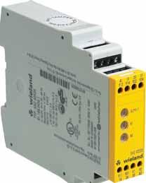
46 Basic Device with time function SNV 4063KL Basic device for single-channel or two-channel emergency stop and safety gate applications Stop category 0/1 according to EN Applications up to safety category 4 according to EN Safety category of the device: 4 (undelayed contacts)/ 3 (delayed contacts) according to EN OFF-delay time adjustable in the range 0.15 to 3 s or 1.5 to 30 s Control through contacts or semiconductors Reset button monitoring, cross monitoring, synchrocheck 3 enabling current paths (2 undelayed, 1 OFF-delayed) Applications Protection of people and machinery Monitoring of emergency stop applications Monitoring of safety gates Termination of braking operations through OFF-delay time Function Device and function description With the supply voltage applied to terminals A1/A2 and the emergency stop circuit closed, the control logic is activated with the reset button. This controls controls the K1 to K4 relays that become self-locking (when starting through reset button monitoring after the response time). After this switch-on phase the 3 enabling current paths are closed (terminals 13/14, 23/24 and 37/38). Three LEDs display the state of the relays K1/K2, K3/K4 and the supply voltage. If the emergency stop button is activated, the current supplies for the relays K1 to K4 are interrupted. The undelayed enabling current paths (terminals 13/14, 23/24) are opened with release time tr1 while the off-delayed enabling current path (terminals 37/38) is opened after the pre-set OFF-delay time tr2. The OFF-delay time can be adjusted infinitely in the range 0.15 to 3 s or 1.5 to 30 s. With a two-channel control and cross-monitoring wiring of the sensor circuit, additional errors such as shunt fault or ground fault can be detected. An electronic fuse protects the device against damage. After the cause of the malfunction has been removed, the device is operational again after approx. 3 s. Reset button monitoring The device can be started either with the falling edge or with the rising edge (terminals S34 or S35). For emergency stop applications with manual start the button must be connected to terminals S33/S34. The device is enabled only with the falling edge of the reset signal. For starting the reset button must be pressed and released. For safety gate applications in which an automatic start shall be performed it is necessary to jumper terminals S33/S35. The device will react at the rising edge of input S12 that is internally connected to S33. Synchrocheck The use of safety limit switches for single-channel or two-channel circuits in safety gate applications depends on the required safety level. The device offers a two-channel control along with an optional synchrocheck of the limit switches. A synchronous time ts 0.5 s requires limit switches positioned in a way that channel 1, terminals S11/S12, closes before channel 2, terminals S21/S22. If channel 2 closes before channel 1, the synchronous time is ts =. Pluggable terminal Device connection Pluggable terminal Device connection Device connection Pluggable terminal Device connection Pluggable terminal 46
47 Overview of devices / Part numbers Type Release delay Rated voltage Terminals Part no. Std. Pack SNV 4063KL 3 s DC 24 V Screw terminals, fixed R s DC 24 V Screw terminals, fixed R SNV 4063KL-A 3 s DC 24 V Screw terminals, pluggable R s DC 24 V Screw terminals, pluggable R SNV 4063KL-C 3 s DC 24 V Cage clamp, pluggable R Technical data Function according to EN Emergency stop relay for controlled stop Function display 3 LEDs, green Function diagram FD W, FD W Power supply circuit min. typ. max. Rated voltage UN DC 20.4 V DC 24 V DC 26.4 V Rated consumption DC 2.6 W Residual ripple U ss 2.4 V Control circuit Rated output voltage S11/S33 DC 22 V for supply of inputs S34, S35, S12, S31, S22 Rsponse time / recovery time Fuse (PTC thermistor) 2 s/3 s Rated current / peak current S12 25 ma/50 ma Rated current / peak current S31, S22 25 ma/100 ma Rated current / peak current S34, S35 40 ma/50 ma Response time t A1 (with reset button monitoring) on S34 30 ms Response time t A2 (without reset button monitoring) on S ms Release time t R1 K1, K2 with emergency stop 25 ms Release time t R2 K3, K4 (2 setting ranges, infinitely adjustable, unbuffered) 0.15 s ± 16 % 3 s ± 16 % 1.5 s ± 16 % 30 s ± 16 % Minimum ON time t M S34-S ms 3 s ON time t M S33-S ms Recovery time t W (start) 500 ms Synchronous time t S 100 ms 500 ms Output circuit Contact assignment 2 enabling current paths, undelayed, NO contact, positively driven 1 enabling current path, OFF-delayed, NO contact, positively driven Rated switching voltage U n AC/DC 230 V Max. continuous current I n per contact 6 A Max. total current of all current paths 12 A Application category according to EN AC-15: U e 230 V AC, I e 4 A (3600 switching cycles/h) DC-13: U e 24 V DC, I e 5 A (360 switching cycles/h) Short-circuit protection max. fuse 6 A class gg or circuit breaker with trigger characteristic B or C General data Creepage distances and clearances between the circuits according to EN Rated impulse voltage 4 kv Overvoltage category III Degree of pollution of the device: inside / outside 2/3 Rated voltage AC 300 V Protection degree according to DIN EN (housing / terminals) IP 40/IP 20 Ambient temperature / storage temperature C/ C Dimension diagram K 4-1 (screw terminals / K 4-2 (pluggable terminals) Wire ranges fine-stranded / solid 2x mm 2 /1x mm 2 or fine-stranded with ferrules 1x mm 2 /2x mm 2 Permissible torque Nm for UL and CSA applications Wire ranges AWG only use Cu wires Max. tightening torques 0.79 in-lbs Weight 0.2 kg Accessories Approvals 4000 series 47
48 Basic Device with time function SNV 4063KP Basic device for single-channel or two-channel emergency stop and safety gate applications with access delay Stop category 0 according to EN Applications up to safety category 4/3 according to EN Safety category of the device: 4 (undelayed contacts)/ 3 (delayed contacts) according to EN OFF-delay time adjustable in the range 0.15 to 3 s or 1.5 to 30 s Control through contacts or semiconductors Reset button monitoring, cross monitoring, synchrocheck 3 enabling current paths (2 undelayed, 1 ON-delayed) Applications Protection of people and machinery Monitoring of interlocking installation with position switches and integrated locking ON-delay unlocking of the solenoid integrated in the position switches Function Device and function description With supply voltage applied to terminals A1/A2, the relays K3 and K4 (terminals 37/38) start with the pre-selected ON-delay time. The ON-delay time ta1 can be adjusted infinitely in the range 0.15 to 3 s or 1.5 to 30 s according to the device type. The device is enabled by pressing the reset button. The following operating modes can be selected: Operating mode with reset button monitoring (evaluation of the falling edge; manual start) The reset button must be connected to S34 through terminal S33. For starting the relay the reset button must be pressed. Relays K3 and K4 (terminals 37/38) will switch into the OFF position. With the falling edge of the reset signal the reset is completed and activates the relays K1 and K2, which become self-locking after the response time ta3. After this switch-on phase the 2 enabling current paths defined for the output are closed (terminals 13/14, 23/24). With the emergency stop command the power supply to relays K1 and K2 is interrupted. The enabling current paths (terminals 13/14, 23/24) are immediately opened with release time tr, and the relays K3 and K4 will start after the pre-set ON-delay time ta1, terminals 37/38. Three LEDs display the state of the relays K1/K2, K3/K4 and the supply voltage. Operating mode without reset button monitoring (evaluation of the rising edge; automatic start) For monitoring of interlocking installations with locking mechanism or safety gate applications in which an automatic start shall be performed it is necessary to jumper terminals S33/S35. The device will react at the rising edge of input S12 that is internally connected to S33. Relays K3 and K4 (terminals 37/38) will switch into the OFF position. With the rising edge of input S12 the relay K1 is activated and response time ta2 started. When the time has elapsed, the 2 enabling current paths are closed (terminals 13/14, 23/24). With a stop command the power supply to relays K1 and K2 is interrupted. The enabling current paths (terminals 13/14, 23/24) are immediately opened with release time tr, and the relays K3 and K4 will start after the pre-set ON-delay time ta1, terminals 377/38. With a two-channel control and cross-monitoring wiring of the sensor circuit, additional errors such as shunt fault or ground fault can be detected. An electronic fuse protects the device against damage. After the cause of the malfunction has been removed, the device is operational again after approx. 3 s. Pluggable terminal Device connection Pluggable terminal Device connection Device connection Pluggable terminal Device connection Pluggable terminal 48
49 Overview of devices / Part numbers Type OFF-delay Rated voltage Terminals Part no. Std. Pack SNV 4063KP 3 s DC 24 V Screw terminals, fixed R s DC 24 V Screw terminals, fixed R SNV 4063KP-A 3 s DC 24 V Screw terminals, pluggable R s DC 24 V Screw terminals, pluggable R Technical data SNV 4063KP Function according to EN Function display Function diagram Emergency stop relay for access delay combined with locking mechanism 3 LEDs, green FD W, FD W Power supply circuit min. typ. max. Rated voltage U N DC 20.4 V DC 24 V DC 26.4 V Rated consumption DC 1.8 W Residual ripple U ss 2.4 V Control circuit Rated output voltage S11/S33 DC 22 V for supply of inputs S34, S35, S12, S31, S22 Rsponse time / recovery time Fuse (PTC thermistor) 2 s/3 s Rated current / peak current S12, S31, S22 25 ma/100 ma Rated current / peak current S34, S35 40 ma/50 ma Response time t A1 (2 setting ranges, infinitely adjustable, unbuffered) 0,15 s ± 16 % 30 ms 3 s ± 16 % at emergency stop 1.5 s ± 16 % 30 s ± 16 % Response time t A2 /t A3 700 ms/30 ms Release time t R at emergency stop 40 ms ON time t M S33 - S ms 3 s ON time t M S33 - S ms Recovery time t W (start) 500 ms Synchronous time t S 100 ms 500 ms Output circuit Contact assignment 2 enabling current paths, undelayed, NO contact, positively driven 1 enabling current path, ON-delayed, NO contact, positively driven Rated switching voltage U n AC/DC 230 V Max. continuous current I n per contact 6 A Max. total current of all current paths 12 A Application category according to AC-15: U e 230 V AC, I e 4 A (3600 switching cycles/h) EN DC-13: U e 24 V DC, I e 5 A (360 switching cycles/h) Short-circuit protection max. fuse 6 A class gg or circuit breaker with trigger characteristic B or C General data Creepage distances and clearances between the circuits according to EN Rated impulse voltage 4 kv Overvoltage category III Degree of pollution of the device: inside / outside 2/3 Rated voltage AC 300 V Protection degree according to DIN EN (housing / terminals) IP 40/IP 20 Ambient temperature / storage temperature C/ C Dimension diagram K 4-1 (screw terminals / K 4-2 (pluggable terminals) Wire ranges fine-stranded / solid 2x mm 2 /1x mm 2 or fine-stranded with ferrules 1x mm 2 /2x mm 2 Permissible torque Nm for UL and CSA applications Wire ranges AWG only use Cu wires Max. tightening torques 0.79 in-lbs Weight 0.2 kg Accessories Approvals 4000 series 49

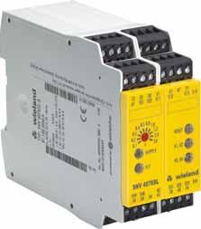
 OFF-delay with retriggering (SNV 4274SL) Safe ON-delay (SNV 4074ST) Up")

50 Basic Device with timer function SNV 4074SL /SNV 4076SL /SNV 4274SL /SNV 4074ST Safety switching devices SNV with timer function The devices are suitable for all applications that require a safe timing sequence. The devices have an application-oriented design and meet all requirements of the currently valid safety standards EN and EN ISO For timer functions the user can choose among devices with ON-delay or OFF-delay. Applications Mechanical engineering Controlled stop of drives Process industry Function Safe OFF-delay (SNV 4074SL / SNV 4076SL) OFF-delay with retriggering (SNV 4274SL) Safe ON-delay (SNV 4074ST) Up to 4 instantaneous contacts and 4 time contacts With/without restart inhibit Supply voltage of DC 24 V to AC 230 V Alternatively screw or spring clamp terminals Construction width of 45 mm Technical data SNV 4074SL / SNV 4076SL SNV 4274SL / SNV 4074ST Function according to EN Emergency stop relay Emergency stop relay Release delay time t RV, adjustable by resting rotary switch 0.1 / 0.2 / 0,3 / 0.4 / 0.5 / 0,8 / 1.0 / 1.5 / 2.0 / 3.0 0,15 s bis 3 s Release delay time t RV or on-delay t ON steplessly adjustable 0* / 2.0 / 4,0 / 6,0 / 8,0 / 10 / 15 / 20 / 25 / s bis 30 s 0* / 20 / 40 / 60 / 80 / 100 / 150 / 200 / 250 / s bis 300 s Power supply circuit Rated voltage DC 24 V / AC V DC 24 V / AC V Operating voltage range x U N x U N Output circuit Release time t R 15 ms 15 ms Contact type positively driven positively driven Rated switching voltage U n AC / DC 230 V AC / DC 230 V Max. continuous current I n per contact 6 A 6 A Application category according to EN AC-15: U e 230 V AC, I e 1.5 A AC-15: U e 230 V AC, I e 1.5 A DC-13: U e 24 V DC, I e 1.2 A DC-13: U e 24 V DC, I e 1.2 A General data Creepage distances and clearances between the circuits according to EN according to EN Protection degree according to DIN EN (housing / terminals) IP 40 / IP 20 IP 40 / IP 20 Ambient temperature, operating range C C Approvals (coming soon) Standards EN 62061, EN 61508, EN 954-1, EN ISO , EN EN 62061, EN 61508, EN 954-1, EN ISO , EN SNV 4074SL SNV 4076SL SNV 4074ST 50
51 Type Rated voltage Terminals Part no. Std. Pack SNV 4074SL, 3s DC 24 V Screw terminals, fixed R SNV 4074SL, 30s DC 24 V Screw terminals, fixed R SNV 4074SL, 300s DC 24 V Screw terminals, fixed R SNV 4074SL-A, 3s DC 24 V Screw terminals, pluggable R SNV 4074SL-A, 30s DC 24 V Screw terminals, pluggable R SNV 4074SL-A, 300s DC 24 V Screw terminals, pluggable R SNV 4074SL-C, 3s DC 24 V Cage clamp, pluggable R SNV 4074SL-C, 30s DC 24 V Cage clamp, pluggable R SNV 4074SL-C, 300s DC 24 V Cage clamp, pluggable R SNV 4074SL, 3s AC V Screw terminals, fixed R SNV 4074SL, 30s AC V Screw terminals, fixed R SNV 4074SL, 300s AC V Screw terminals, fixed R SNV 4074SL-A, 3s AC V Screw terminals, pluggable R SNV 4074SL-A, 30s AC V Screw terminals, pluggable R SNV 4074SL-A, 300s AC V Screw terminals, pluggable R SNV 4074SL-C, 3s AC V Cage clamp, pluggable R SNV 4074SL-C, 30s AC V Cage clamp, pluggable R SNV 4074SL-C, 300s AC V Cage clamp, pluggable R SNV 4076SL, 3s DC 24 V Screw terminals, fixed R SNV 4076SL, 30s DC 24 V Screw terminals, fixed R SNV 4076SL, 300s DC 24 V Screw terminals, fixed R SNV 4076SL-A, 3s DC 24 V Screw terminals, pluggable R SNV 4076SL-A, 30s DC 24 V Screw terminals, pluggable R SNV 4076SL-A, 300s DC 24 V Screw terminals, pluggable R SNV 4076SL-C, 3s DC 24 V Cage clamp, pluggable R SNV 4076SL-C, 30s DC 24 V Cage clamp, pluggable R SNV 4076SL-C, 300s DC 24 V Cage clamp, pluggable R SNV 4076SL, 3s AC V Screw terminals, fixed R SNV 4076SL, 30s AC V Screw terminals, fixed R SNV 4076SL, 300s AC V Screw terminals, fixed R SNV 4076SL-A, 3s AC V Screw terminals, pluggable R SNV 4076SL-A, 30s AC V Screw terminals, pluggable R SNV 4076SL-A, 300s AC V Screw terminals, pluggable R SNV 4076SL-C, 3s AC V Cage clamp, pluggable R SNV 4076SL-C, 30s AC V Cage clamp, pluggable R SNV 4076SL-C, 300s AC V Cage clamp, pluggable R SNV 4274SL, 3s DC 24 V Screw terminals, fixed R SNV 4274SL, 30s DC 24 V Screw terminals, fixed R SNV 4274SL, 300s DC 24 V Screw terminals, fixed R SNV 4274SL-A, 3s DC 24 V Screw terminals, pluggable R SNV 4274SL-A, 30s DC 24 V Screw terminals, pluggable R SNV 4274SL-A, 300s DC 24 V Screw terminals, pluggable R SNV 4274SL-C, 3s DC 24 V Cage clamp, pluggable R SNV 4274SL-C, 30s DC 24 V Cage clamp, pluggable R SNV 4274SL-C, 300s DC 24 V Cage clamp, pluggable R SNV 4274SL, 3s AC V Screw terminals, fixed R SNV 4274SL, 30s AC V Screw terminals, fixed R SNV 4274SL, 300s AC V Screw terminals, fixed R SNV 4274SL-A, 3s AC V Screw terminals, pluggable R SNV 4274SL-A, 30s AC V Screw terminals, pluggable R SNV 4274SL-A, 300s AC V Screw terminals, pluggable R SNV 4274SL-C, 3s AC V Cage clamp, pluggable R SNV 4274SL-C, 30s AC V Cage clamp, pluggable R SNV 4274SL-C, 300s AC V Cage clamp, pluggable R SNV 4074ST, 3s DC 24 V Screw terminals, fixed R SNV 4074ST, 30s DC 24 V Screw terminals, fixed R SNV 4074ST, 300s DC 24 V Screw terminals, fixed R SNV 4074ST-A, 3s DC 24 V Screw terminals, pluggable R SNV 4074ST-A, 30s DC 24 V Screw terminals, pluggable R SNV 4074ST-A, 300s DC 24 V Screw terminals, pluggable R SNV 4074ST-C, 3s DC 24 V Cage clamp, pluggable R SNV 4074ST-C, 30s DC 24 V Cage clamp, pluggable R SNV 4074ST-C, 300s DC 24 V Cage clamp, pluggable R SNV 4074ST, 3s AC V Screw terminals, fixed R SNV 4074ST, 30s AC V Screw terminals, fixed R SNV 4074ST, 300s AC V Screw terminals, fixed R SNV 4074ST-A, 3s AC V Screw terminals, pluggable R SNV 4074ST-A, 30s AC V Screw terminals, pluggable R SNV 4074ST-A, 300s AC V Screw terminals, pluggable R SNV 4074ST-C, 3s AC V Cage clamp, pluggable R SNV 4074ST-C, 30s AC V Cage clamp, pluggable R SNV 4074ST-C, 300s AC V Cage clamp, pluggable R series
52 Contact Expansion Relay SNE 4003K Output expansion with relay for basic devices in safety applications Stop category 0 and 1 according to EN (see Notes ) Applications up to safety category 4 according to EN (see Notes ) Safe isolation according to EN Single-channel or two-channel control 3 enabling current paths (NO contact), 2 signaling current paths (NC contact) Broad input voltage range from DC 15 to 30 V Suitable for semiconductor control Applications Expansion of a basic device is enabling current paths Contact expansion in safety equipment system Output power increase for light curtains Function Device description The SNE 4003K is an expansion device for basic devices (such as safety switching devices, light curtains, laser scanners) that are part of the machine s safety equipment and are used for protecting people, material and machine. The device is designed with two channels and redundancy. The enabling current paths are separated from the control circuits and signaling circuits with creepage distances and clearances > 5.5 mm (safe isolation). There is basic insulation to separate the enabling current paths from one another and the control circuits from the signaling current paths. The broad input voltage range of DC 15 V to DC 30 V makes the SNE 4003K ideal for single-channel or two-channel control by semiconductors. Description of functions Input voltage to the SNE 4003K is routed via one or two enabling current paths of a basic device. When the input voltage is applied relays K1 and K2 switch into the ON position. After this switch-on phase, enabling current paths 13/14, 23/24, 33/34 are closed and feedback current path Y1/Y2 and signaling current path 41/42 are opened. This is displayed through two LEDs, K1 and K2, which are assigned to relays K1 and K2. If the enabling current paths of the basic device are opened when the emergency stop button is operated, relays K1 and K2 on the SNE 4003K switch back into the OFF position. The enabling current paths open and the feedback current path closes. Feedback current path Y1/Y2 prevents the basic device from switching on again before K1 or K2 releases. SNE 4003K / K-A 52
53 Overview of devices / Part numbers Type Rated voltage Terminals Part no. Std. Pack SNE 4003K DC 24 V Screw terminals, fixed R SNE 4003K-A DC 24 V Screw terminals, pluggable R Technical data SNE 4003K Function according to EN Emergency stop expansion relay Function display 2 LEDs green Function diagram FD W Control circuits B1/B2 and B3/B4 Rated voltage DC 24 V Input voltage range DC 15 V DC 30 V Rated consumption 1.2 W Rated current / max. peak current 50 ma/500 ma Make time t E K1, K2 < 40 ms Response time t A K1, K2 < 20 ms Recovery time t W 40 ms Output circuits Contact assignment 3 enabling current paths (NO contact) 1 signaling path (NC contact, parallel) 1 feedback path (NC contact, serial) positively driven Contact type positively driven Rated switching voltage U n AC 230 V/DC 300 V Max. continuous current I n per enabling current path 6 A Max. total current of all enabling current paths 12 A Max. continuous current I n per signaling current path 2 A Application category according to EN AC-15: U e 230 V, I e 3 A DC-13: U e 24 V, I e 2.5 A Short-circuit protection max. fuse 6 A class gg or circuit breaker with trigger characteristic B or C Mechanical life 1x10 6 switching cycles General Data Creepage distances and clearances between the circuits according to EN Overvoltage category IV Rated impulse voltage 6 kv Rated voltage AC 300 V Test AC voltage 2 kv Degree of pollution 3 outside, 2 inside Protection degree according to DIN EN (housing / terminals) IP 40/IP 20 Ambient temperature C Dimension diagram K 4-1 (screw terminals / K 4-2 (pluggable terminals) Wire ranges fine-stranded / solid 2x mm 2 /1x mm 2 or fine-stranded with ferrules 1x mm 2 /2x mm 2 Permissible torque Nm for UL and CSA applications Wire ranges AWG only use Cu wires Max. tightening torques 5.25 in-lbs Weight 0.21 kg Accessories Approvals 4000 series 53
 Single-channel or two-channel control SNE 4004K: 4 enabling current paths, undelayed (NO contact) 3 signaling current paths, undelayed (NC contact) SNE")
54 Contact Expansion Relay SNE 4004K/SNE 4004KV Output expansion with relay for basic devices in safety applications Stop category 0 and 1 according to EN (see Notes ) Applications up to safety category 4 according to EN (see Notes ) Single-channel or two-channel control SNE 4004K: 4 enabling current paths, undelayed (NO contact) 3 signaling current paths, undelayed (NC contact) SNE 4004KV: 4 enabling current paths, OFF-delayed (NO contact) 3 signaling current paths, OFF-delayed (NC contact), Time buffering Applications Expansion of a basic device s enabling current paths Contact expansion in safety equipment Function SNE 4004K Supply voltage to the SNE devices is routed via an enabling current path of a basic device. When the supply voltage is applied relays K1 and K2 switch into the ON position. After this switch-on phase the four enabling current paths 13/14, 23/24, 33/34, 43/44 (of the SNE 4004K) or 17/18, 27/28, 37/38, 47/48 (of the SNE 4004KV) are closed and the feedback current path Y1/Y2 is open. This is displayed through two LEDs that are assigned to relays K1 and K2. When the enabling current paths of the basic device are opened through the operation of the emergency stop button, relays K1 and K2 on the SNE 4004K switch back into the OFF position. The enabling current paths open and the feedback current path closes. Feedback current path Y1/Y2 prevents the basic device from switching on again before K1 or K2 releases. SNE 4004KV The functions of this device correspond to those of the SNE 4004K. The SNE 4004KV is available with the following four OFF-delay times tr1: 0.5 s; 1 s; 2 s and 3 s. The device has an OFF-delay time that is enabled through capacitors. This causes the OFF-delay time R1 to elapse completely even in case of failure of the power supply (A1/A2). It cannot be deleted before it has elapsed. Upon timing-out the relays K1 and K2 switch into the OFF position. OFF-delay times of > 0 s correspond to stop category 1. SNE 4004K-A and SNE 4004KV-A The functions of these devices correspond to those of the SNE 4004K or SNE 4004KV. Devices with the -A identification in their type designation are equipped with four removable pluggable terminals (see the K4-2 dimension diagram). This feature allows a quick installing/removing operation. The terminal locations are coded and not interchangeable. Pluggable terminal Device connection Pluggable terminal Device connection Device connection Pluggable terminal Device connection Pluggable terminal Pluggable terminal Device connection Pluggable terminal Device connection Device connection Pluggable terminal Device connection Pluggable terminal 54
55 Overview of devices / Part numbers Type Release delay Rated voltage Terminals Part no. Std. Pack SNE 4004K AC/DC 24 V Hz Screw terminals, fixed R SNE 4004K-A AC/DC 24 V Hz Screw terminals, pluggable R SNE 4004K-C AC/DC 24 V Cage clamp, pluggable R SNE 4004KV 0.5 s DC 24 V Screw terminals, fixed R s DC 24 V Screw terminals, fixed R s DC 24 V Screw terminals, fixed R s DC 24 V Screw terminals, fixed R SNE 4004KV-A 0.5 s DC 24 V Screw terminals, pluggable R s DC 24 V Screw terminals, pluggable R s DC 24 V Screw terminals, pluggable R s DC 24 V Screw terminals, pluggable R SNE 4004KV-C 0.5 s DC 24 V Cage clamp, pluggable R s DC 24 V Cage clamp, pluggable R s DC 24 V Cage clamp, pluggable R s DC 24 V Cage clamp, pluggable R Technical data SNE 4004K/SNE 4004KV Function according to EN Emergency stop expansion relay Function display 2 LEDs green Function diagram FD W, FD W Power supply circuit min. typ. max. Rated voltage UN SNE 4004K AC/DC 20.4 V AC/DC 24 V AC/DC 26.4 V Rated voltage UN SNE 4004KV DC 20.4 V DC 24 V DC 26.4 V Rated consumption DC 1.0 W Rated consumption AC 1.5 W/2.7 VA Residual ripple DC 2.4 V SS Rated frequency AC 50 Hz 60 Hz Rated current / peak current 65 ma/1000 ma 80 ma/1800 ma Response time ta 20 ms Release time tr2 SNE 4004K with emergency stop 40 ms Minimum ON time tm SNE 4004KV 75 ms Release time tr1 SNE 4004KV (buffered) 0.5 s/1 s/2 s/3 s Mean value of the error SNE 4004KV ± 20 % Dispersion SNE 4004KV ± 2 % Feedback current path Y1/Y2 1 NC contact, positively driven Rated switching voltage U n DC 24 V Max. continuous current I n 0.1 A Contact material Ag alloy, gold-plated Output circuits Enabling current paths 4 NO contacts, positively driven Rated switching voltage U n AC/DC 230 V Max. continuous current I n /max. total current 6 A/12 A Application category according to 3600 h -1 AC-15: U e 230 V, I e 6 A / DC-13: U e 24 V, I e 3 A EN h -1 DC-13: U e 24 V, I e 6 A Short-circuit protection max. fuse 6 A class gg or circuit breaker with trigger characteristic B or C Mechanical life 10x10 6 switching cycles Contact material Ag alloy, gold-plated Signaling current paths 2 NC contacts, positively driven Rated operating voltage U n AC/DC 230 V Max. continuous current I n 2 A Contact material Ag alloy, gold-plated General data Creepage distances and clearances between the circuits according to EN Overvoltage category III Rated impulse voltage 4 kv Rated voltage AC 300 V Degree of pollution of the device: inside / outside 2/3 Protection degree according to DIN EN (housing / terminals) IP 40/IP 20 Ambient temperature / storage temperature C/ C Dimension diagram K 4-1 (screw terminals / K 4-2 (pluggable terminals) Wire ranges fine-stranded / solid 2x mm 2 /1x mm 2 or fine-stranded with ferrules 1x mm 2 /2x mm 2 Permissible torque Nm Weight 0.20 kg Accessories Approvals series
 Expansion of a basic device s enabling current paths Contact expansion in safety equipment 8 enabling current paths, 3 signaling current paths, 1 feedback current")

56 Contact Expansion Relay SNE 4008S Output expansion with relay for basic devices in safety applications Stop category 0 according to EN (see Notes ) Applications up to safety category 4 according to EN (see Notes ) Expansion of a basic device s enabling current paths Contact expansion in safety equipment 8 enabling current paths, 3 signaling current paths, 1 feedback current path Applications Expansion of a basic device s enabling current paths Contact expansion in safety equipment Up to 8 safe enables through a control signal Function Device description The device is designed with a single channel redundant with positively driven relays. It has a feedback current path with a serial NC contact chain of positively driven relays involved in the switching operation for a safe feedback to the basic device. Two serially switched NO contacts (one NO contact for each redundant relay) form an enabling current path. Due to this design it is generally possible to establish a safety circuit with self-monitoring on each ON-OFF cycle (SK4) in conjunction with a suitable basic device. As the device is designed with a single channel, it must be installed in a control cabinet with permanent wiring in order to prevent short circuits of the control lines. A basic isolation separates the enabling current paths from one another as well as from the control circuits and the signaling path. Description of functions Input voltage to the device is routed via one or two enabling current paths of a basic device. When the input voltage is applied relays K1, K2, K3 and K4 switch into the ON position. After this switch-on phase the enabling current paths 13/14, 23/24, 33/34, 43/44 and 63/64, 73/74, 83/84, 93/94 are closed and the feedback current path Y1/Y4 as well as the signaling current paths 51/52, 101/102 and 111/112 are opened. This is displayed through the LEDs K1, K2, K3 and K4 which are assigned to relays K1, K2, K3 and K4. When the enabling current paths of the basic device are opened through the operation of the emergency stop button, relays K1, K2, K3 and K4 switch back into the OFF position. The enabling current paths open and the feedback current path closes. Feedback current path Y1/ Y4prevents the basic device from switching on again before K1, K2, K3 and K4 releases. The feedback current path Y1/Y2 must be wired to the reset or feedback loop of the basic device. SNE 4008S * pre-wired by the manufacturer 56
57 Overview of devices / Part numbers Type Rated voltage Terminals Part no. Std. Pack SNE 4008S AC/DC 24 V Hz Screw terminals, fixed R SNE 4008S-A AC/DC 24 V Hz Screw terminals, pluggable R SNE 4008S-C AC/DC 24 V Cage clamp, pluggable R Technical data SNE 4008S Function according to EN Function display Function diagram Emergency stop expansion relay 4 LEDs green FD W Control circuit min. typ. max. Rated voltage U N AC/DC 20.4 V AC/DC 24 V AC/DC 26.4 V Rated consumption DC 2.4 W 2.9 W Rated consumption AC 2.8 W/4,9 VA 3.4 W/6,0 VA Residual ripple DC 2.4 V SS Rated frequency AC 50 Hz 60 Hz Rated current / peak current 125 ma/2000 ma 150 ma/3500 ma Response time t A 20 ms 40 ms Release time t R 35 ms 50 ms Recovery time t W 100 ms Feedback current path Y1/Y4 1 NC contact, positively driven Rated switching voltage U N AC/DC 24 V Max. continuous current I n 1 A Contact material Ag alloy, gold-plated Output circuits Enabling current paths 8 NO contacts, positively driven Rated switching voltage U n AC 230 V/DC 300 V Max. continuous current I n /max. total current 13/14, 23/24, 33/34, 43/44 6 A/12 A Max. continuous current I n /max. total current 63/64, 73/74, 83/84, 93/94 6 A/12 A Application category according to 3600 h -1 AC-15: U e 230 V, I e 6 A / DC-13: U e 24 V, I e 3 A EN h -1 DC-13: U e 24 V, I e 6 A Short-circuit protection, max. fuse insert 6 A class gg or circuit breaker with trigger characteristic B or C Contact material Ag alloy, gold-plated Signaling current paths 51/52, 101/102, 111/112 3 NC contacts, positively driven Rated operating voltage U n AC 230 V/DC 300 V Max. continuous current I n 6 A Contact material Ag alloy, gold-plated General data Creepage distances and clearances between the circuits according to EN Safe isolation no Isolation Control circuits output circuits Basic isolation Output circuit output circuit Basic isolation 4000 series Overvoltage category III Rated impulse voltage 4 kv Rated voltage AC 300 V Test AC voltage 2 kv Degree of pollution of the device: inside / outside 2/3 Protection degree according to DIN EN (housing / terminals) IP 40/IP 20 Ambient temperature / storage temperature C/ C Dimension diagram S10-1 (screw terminals)/s 10-2 (pluggable terminals) Wire ranges fine-stranded / solid 2x mm 2 /1x mm 2 or fine-stranded with ferrules 1x mm 2 /2x mm 2 Permissible torque Nm Weight 0.44 kg Accessories Approvals 57
58 58


59 samos samos samos safety made simple samos stands for modular safety system. The safety system with just a few multi-functional basic modules is built on the modular kit principle and grows module by module along with the safety task. Function blocks for many safety tasks can be selected. Parameterization with screwdriver No programming system required Cost advantages after just a few safety circuits Link to fieldbuses and Industrial Ethernet All safety functions are set with a screwdriver without programming software and can be read at the device. samos 59
60 60

61 samos samos samos, the electronic safety system from Wieland Electric, offers the functionality that mechanical engineers and system providers want. samos combines a wide variety of safety sensors which monitor a machine or system for technical safety either individually, in combination or all together. samos replaces special devices with pre-defined, practiceoriented function blocks for monitoring emergency stop, position switches, two-hand buttons and light curtains, for example. samos uses safe logical link functions for simple creation of dependent/independent safety zones. samos offers comprehensive diagnosis by fieldbus via gateways for Profibus-DP, CANopen and DeviceNet or via Industrial Ethernet. samos 61
62 62


63 samos samos easy diagnosis to go Central Diagnosis via Field Bus If you integrate a gateway the higher-order controller will always be kept informed of the system status. The modules for Profibus- DP, CANopen and DeviceNet provide the user with system information for diagnosis purposes. It can be sent to other bus stations (e.g. PLC) via the field bus. Conversely, four addressable outputs on the gateway allow you, for example, to trigger a safety function reset via the field bus or Industrial Ethernet without influencing the safety modules of the samos system. samos 63


64 Example: Single Functions Example: Combination Functions Emergency stop Safety door Controlled stopping Monitoring BWS type 4 Monitoring BWS type 2 with testing Example: Dual Functions Testable PDF sensors Safe position monitoring Example: Special Functions Static valve monitoring Jog mode Two-hand applications to IIIA and IIIC 4-wire switching mats Set release delay of output Q4 or Q3 and Q4 Setup mode MUTING and BYPASS 64

 depends on the sensor, the wiring and the installation.")

65 samos samos Diversity of function samos offers input circuit functions for a wide range of typical machine-building and plant engineering functions through to special functions for special sensors. Even a stand-alone base module offers numerous application options and covers the functionality of many types of conventional single safety switching device. The maximum control category (2, 3 or 4; EN 954-1) depends on the sensor, the wiring and the installation. Economical safety With all its advantages samos is more cost-effective than the normal safety switching devices, even with just a few safety channels. Just two samos modules and 45 mm can replace up to 6 dualchannel safety switching devices at the same cost. And for larger configurations the samos system is the clear winner. Another advantage: modular flexibility makes investment mistakes almost impossible. samos 65


66 LG2 FB2 LG1 FB1 SD Zone 0 Zone 1 Zone 2 Field bus Easy Practicability A machining center with two machines, a robot for handling the parts, feed belts a standard setup in industrial manufacturing. Comprehensive safety monitoring is obligatory. What you need is flexibility, so that not every malfunction leads to total shutdown, and, for example, setup mode is still possible. 66

67 samos samos Safety Zones samos offers the flexible solution for this safety task, through its modular design and the possibility of setting up input group hierarchies. This means you can create zones where different safety responses are triggered according to place and type. Operating one of the three emergency stop switches in zone 0 shuts the machining center down completely in zones 0, 1 and 2. If light curtain LG1 is interrupted by a person, the machines, the robot and feed belt FB1 are shut down. If light curtain LG2 is interrupted by a person, all dangerous motions and feed belt FB2 are shut down. Muting sensors bridge the light curtain function briefly to allow normal material transport through the light curtain. samos also monitors the muting sensors. When the safety door SD is opened only zone 2 is shut down. Feed belt FB2 can still transport material to the next machining station. However, personnel can enter the shut-down zone 2 for setup operation after the lockswitch and the enabling button have been operated. Jog mode is used, for example, for movements during setting up. Emergency stop and light curtain monitoring remain active. The settable release delay on the samos outputs means that in all robot and machine shutdowns, stop category 1 is used for controlled stopping. samos The optional field bus connection sends the input/output status, for example to a higher-order PLC. The PLC in turn can reset individual zones via the field bus. 67


68 SA-EN-IP SA-EN-MOD The Ethernet gateways SA-EN-IP and SA-EN-MOD with integrated switch make it easy for users to link the samos system to systems which use Industrial Ethernet. Setting up precise processing procedures requires safety for the operator. 68
69 samos samos Expansion from min to max Modular design In its maximum configuration samos consists of one basic master module and additional modules to expand function blocks, inputs and outputs. Up to 12 safe active modules (basic slave modules, input modules) In addition up to 4 safe passive output module relays In addition 1 gateway Internal Safety Bus The power voltage is fed to the basic master module and all other basic modules. The powering of the other modules and the communication are handled via the internal safety bus with stable side contact strips no more extra lost part plug connectors needed. samos 69


 Basic slave module Safety module")


70 Basic master module Basic slave module Input module Output module relay Gateway Basic master module Safety module with 8 function blocks, 8 safe inputs and 4 safe outputs (also suitable for stand-alone operation) Basic slave module Safety module with 8 preprogrammed function blocks, 8 safe inputs and 4 safe outputs Input module Expansion module with 10 function blocks and 8 safe inputs Output module relay Expansion modules with 2 or 4 safe, floating relay contacts Gateway Fieldbus or Ethernet gateways for easy diagnosis of the samos system 70


71 samos samos Maximum flexibility Intelligently connected modules The modules are connected to a 36-mm standard DIN rail and pushed together. The obligatory basic module is connected on the left side of the rail and any necessary additional basic slave modules, input modules and output module relays are connected in between. The input modules are permanently coded and are always permanently assigned to a likewise coded basic module, which eliminates any confusion during service work, for instance. The relay modules are integrated in the function via external wiring. If necessary such subsystems made up of basic modules, input modules and output modules can be wired together. This allows the implementation of a wide variety of input/output functions with separate or combined effects. Functions with added value The functions of the basic module and the input modules are set either individually or in combination on the front with 10-position rotary switches (e.g. emergency stop and protective door monitoring with controlled shutdown). Additional functions such as automatic reset, startup and re-startup blocking or retriggering of the off-delay are implemented with terminal configuration. samos The clear and simple user interface helps to implement safe solutions. 71
 Category 4 (EN 954-1) Technical data Function display Power supply circuit Operating voltage range Rated consumption Electrical isolation Power supply circuit")

72 Safety Modules samos Basic Module SA-BM or SA-BS 8 function blocks 4 inputs for safety sensors 4 safe wear-free semiconductor inputs Functionally dependent release delay SILCL 3 (EN ) Performance level PL e (EN ISO ) Category 4 (EN 954-1) Technical data Function display Power supply circuit Operating voltage range Rated consumption Electrical isolation Power supply circuit - Control circuit Secure input circuit I1 I4 Input voltage range Rated current Secure control circuits EN, S1 S3 Input voltage range Rated current Secure output circuits Q1 Q4 Output voltage Output current I n per exit Output circuits X1, X2 Output voltage Output current I n per exit SA-BM, SA-BS 12 LEDs, green/red DC 19.2 V to DC 30 V 1.8 W no DC 15 V to DC 30 V 8 ma DC 15 V to DC 30 V 3 ma DC 24 V 2 A DC 24 V 0.15 A Input module SA-IN 10 Functional modules 2 x 4 inputs for sensors 2 x 4 test signal outputs SILCL 3 (EN ) Performance level PL e (EN ISO ) Category 4 (EN 954-1) Technical data Function display Power supply circuit Operating voltage range Rated consumption Electrical isolation Power supply circuit - Control circuit Secure input circuit I1 I8 Input voltage range Rated current Output circuits X1 X8 Output voltage Output current I n per exit SA-IN 12 LEDs, green/red DC 19.2 V to DC 30 V 1.2 W no DC 15 V to DC 30 V 3 ma DC 24 V 0.15 A 72
 Performance level PL e (EN ISO 13849-1) Category 4 (EN 954-1) Output Module SA-OR-S2 1 x 2 safe enabling with switching up to AC 230 V / 6 A 1 x 1 potential-carrying safe output DC 24 V")
 Technical data SA-OR-S1 / SA-OR-S2 Function display 3 or.")


73 Output Module SA-OR-S1 2 x 2 safe enabling with switching up to AC 230 V / 6 A 2 x outputs DC 24 V / 50 ma 2 x 1 positively driven NC contact for integration in feedback circuits (NO contact) SILCL 3 (EN ) Performance level PL e (EN ISO ) Category 4 (EN 954-1) Output Module SA-OR-S2 1 x 2 safe enabling with switching up to AC 230 V / 6 A 1 x 1 potential-carrying safe output DC 24 V / 50 ma for signaling or safe logical operation 1 x 1 positively driven NC contact for integration in feedback circuits (NO contact) SILCL 3 (EN ) Performance level PL e (EN ISO ) Category 4 (EN 954-1) Technical data SA-OR-S1 / SA-OR-S2 Function display 3 or. 2 LEDs, green Input circuit B1, B2 Input voltage range DC 18 V to DC 30 V Electrical isolation Power supply circuit Input circuit no Electrical isolation Input circuit - Output circuit yes Electrical isolation Power supply circuit - Output circuit yes Rated consumption 2.2 W to 1.1 W Release delay 30 ms Output circuits (Relais) Switching voltage AC 230 V Output current I n per exit 6 A Output circuits (Y14, Y24) Switching voltage DC 30 V Output current I n per exit 75 ma samos The optional switch cover SA-COVER can be snapped onto the front of the safe module to prevent the switch setting from changing after start-up. The cover is leadable and can only be removed with a tool (screwdriver) after the lead has been removed. General Technical data Wire ranges Terminal block fine-stranded / fine-stranded (solid) 2 x 0.14 to 0.75 mm 2 / 1 x 0.14 to 2.5 mm 2 fine-stranded with ferrules 2 x 0.14 to 0.75 mm 2 / 1 x 0.14 to 2.5 mm 2 Spring clamp terminal fine-stranded / fine-stranded (solid) 2 x 0.14 to 1.5 mm 2 fine-stranded with ferrules 2 x 0.25 to 1.5 mm 2 Protection degree according to DIN (housing / terminals) IP40 / IP20 Creepage distances and clearances EN Ambient temperature / storage temperature -25 C C / -25 C C Standards EN 954-1, EN 61508, EN 62061, EN ISO Approvals TÜV, culus 73
74 Safety Modules samos Fieldbus Gateways / Ethernet Gateways samos fieldbus gateways Available for PROFIBUS-DP, CANopen and DeviceNet SA-PROFIBUS-DP SA-CANopen SA-DeviceNet samos Ethernet gateways Available for Modbus/TCP and Ethernet/IP SA-EN-MOD SA-EN-IP Features of the gateways Transmission of samos system information No safety-oriented gateways Setting of the module address on the fieldbus via switches on the front 4 outputs for the activation of the samos system (e.g., reset) Power supply via internal safety bus or fieldbus samos system information Configuration data Input states Output states Fault data (e.g., configuration faults, faults during operation) 74
75 Type Rated voltage Terminals / Notes Part no. Std. Pack SA-BM-S1-4EKL-A, 5s DC 24 V screw terminals, pluggable R SA-BM-S1-4EKL-A, 50s DC 24 V screw terminals, pluggable R SA-BM-S1-4EKL-A, 5min DC 24 V screw terminals, pluggable R SA-BS-S1-4EKL-A, 5s DC 24 V screw terminals, pluggable R SA-BS-S1-4EKL-A, 50s DC 24 V screw terminals, pluggable R SA-BS-S1-4EKL-A, 5min DC 24 V screw terminals, pluggable R SA-IN-S1-K-A DC 24 V screw terminals, pluggable R SA-IN-S2-K-A DC 24 V screw terminals, pluggable R SA-IN-S3-K-A DC 24 V screw terminals, pluggable R SA-IN-S4-K-A DC 24 V screw terminals, pluggable R SA-IN-S5-K-A DC 24 V screw terminals, pluggable R SA-IN-S6-K-A DC 24 V screw terminals, pluggable R SA-OR-S1-4RK-A DC 24 V screw terminals, pluggable R SA-OR-S2-2RK-A DC 24 V screw terminals, pluggable R SA-CANopen-A DC 24 V screw terminals, pluggable R SA-DeviceNet-A DC 24 V screw terminals, pluggable R SA-PROFIBUS-DP-A DC 24 V screw terminals, pluggable R SA-EN-MOD-A DC 24 V screw terminals, pluggable R SA-EN-IP-A DC 24 V screw terminals, pluggable R SA-BM-S1-4EKL-C, 5s DC 24 V cage clamp, pluggable R SA-BM-S1-4EKL-C, 50s DC 24 V cage clamp, pluggable R SA-BM-S1-4EKL-C, 5min DC 24 V cage clamp, pluggable R SA-BS-S1-4EKL-C, 5s DC 24 V cage clamp, pluggable R SA-BS-S1-4EKL-C, 50s DC 24 V cage clamp, pluggable R SA-BS-S1-4EKL-C, 5min DC 24 V cage clamp, pluggable R SA-IN-S1-K-C DC 24 V cage clamp, pluggable R SA-IN-S2-K-C DC 24 V cage clamp, pluggable R SA-IN-S3-K-C DC 24 V cage clamp, pluggable R SA-IN-S4-K-C DC 24 V cage clamp, pluggable R SA-IN-S5-K-C DC 24 V cage clamp, pluggable R SA-IN-S6-K-C DC 24 V cage clamp, pluggable R SA-OR-S1-4RK-C DC 24 V cage clamp, pluggable R SA-OR-S2-2RK-C DC 24 V cage clamp, pluggable R SA-CANopen-C DC 24 V cage clamp, pluggable R SA-DeviceNet-C DC 24 V cage clamp, pluggable R SA-PROFIBUS-DP-C DC 24 V cage clamp, pluggable R samos SA-COVER Switch cover R SA-MANUAL-D samos-manual, D R SA-MANUAL-GB samos-manual, GB R SA-MANUAL-BUS-D samos-gateway-manual, D R SA-MANUAL-BUS-GB samos-gateway-manual, GB R
76 76


77 samos PRO samos PRO samos PRO is a powerful and compact safety controller for machine and plant manufacturing applications. Using modules which are only 22.5 mm in width, programmable safety solutions can be implemented from a total width of 45 mm. samos PRO overview of advantages High degree of flexibility due to extreme compact and modular design Operator control is child s play with the graphic samos PLAN programming system Almost no downtime due to simple diagnosis, simulation and exchangeable program memory Inexpensive due to almost no wiring work and fast commissioning Implementation of complex functions is simple and safe. Simple integration in fieldbus systems and Industrial Ethernet networks samos PRO 77


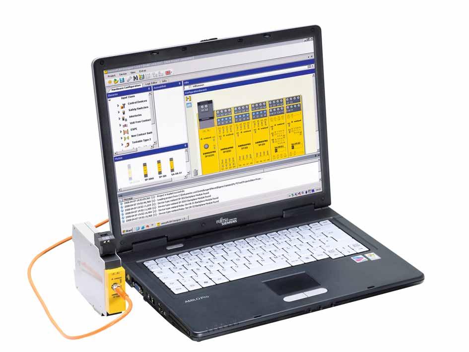

78 78


, Performance Level PL e (EN ISO 13849-1)")
79 samos PRO samos PRO System characteristics samos PRO consists of the safe SP-SCON controller with integrated programming/diagnostic interface and a series of safe SP-SDIO or SP-SDI I/O modules. Appropriate gateways permit communication with fieldbuses or Ethernet networks. Programming is simple and intuitive with the graphic programming user interface samos PLAN using a wide variety of safe function blocks. An exchangeable program memory (samos MEMORY) is also part of the system. samos PRO fulfills category 4 (EN 954-1), Performance Level PL e (EN ISO ) and SIL 3 (EN 62061). Flexible and safe from loss the safe program memory. samos PRO 79


80 SP-SCON Gateway SP-SDIO SP-SDI 1 2 SP-SCON Safe controller module with serial interface and exchangeable program memory Gateway Gateways for bi-directional data communication 3 4 SP-SDIO Expansion module with 8 safe digital inputs and 4 safe digital outputs SP-SDI Expansion module with 8 safe digital inputs 80


81 samos PRO samos PRO the modules samos PRO professional safety samos PRO can simultaneously process up to 96 safe inputs and 48 safe outputs and monitors all types of safety sensors. The system enables extremely short switchoff times of less than 10 milliseconds. Protective facilities can thus be installed near the danger zones of a machine, for example. The application program is stored on the exchangeable program memory which also contains the power supply connection of the system. This means that the application program always remains available in the control cabinet even when memories are being exchanged. Materials must be moved and stored safely in high-shelf storage systems. samos PRO 81


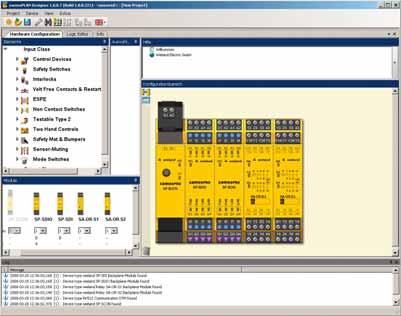
82 82 Simple software helps safe automation.
83 samos PRO samos PLAN the simple way to make programming safe samos PLAN provides the user with a convenient graphic programming interface for samos PRO. Configuration and parameterization of inputs and outputs is completely free. Changes in the user s application can be managed easily with samos PLAN. samos PLAN the programming tool of samos PRO Intuitive, graphic user interface Safe, certified function blocks Simple I/O configuration and parameterization Simulation and online diagnostics Runs under Windows XP,... Punching and pressing in the metal-processing industry must meet highest demands on safety. samos PRO 83


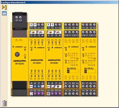


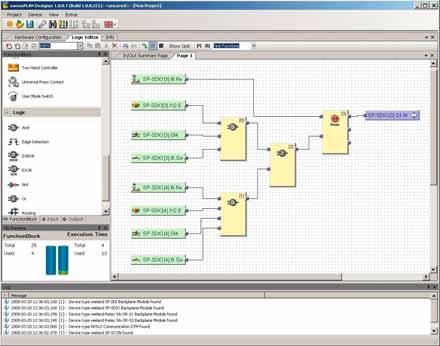
84 84 samos PLAN Programming, simulation and visualization of complex safety tasks


85 samos PRO samos PLAN the programming tool of samos PRO You don t need to master a programming language to be able to solve technical safety tasks with samos PLAN. The graphic programming user interface is intuitive and supports the user with its many automated functions. samos PLAN offers the user many safe, practiceoriented function blocks. For example: Emergency stop functions Protective door and locking functions Light barrier and light curtain functions Muting functions Two-hand and press functions Logic functions Timer and counter functions Operating mode switch Clearly organized and functional the practice-oriented function blocks. samos PRO 85
 Category 4 (EN 954-1) Technical data SP-SCON Function display 2 LEDs, green/red Power supply circuit Operating voltage range DC 16.")
86 Safety Controller samos PRO Controller module SP-SCON Receptacle for removable program memory (to be ordered separately) Serial interface RS-232 SIL CL 3 (EN ) Performance level PL e (EN ISO ) Category 4 (EN 954-1) Technical data SP-SCON Function display 2 LEDs, green/red Power supply circuit Operating voltage range DC 16.8 V to DC 30 V Rated consumption 3 W Electrical isolation Power supply circuit - Control circuit no Input circuits Quantity / type Output circuits Quantity / type General data Protection degree according to DIN (housing / terminals) IP40 / IP20 Creepage distances and clearances EN Ambient temperature / storage temperature -25 C C / -25 C C Standards EN 954-1, EN 61508, EN 62061, EN ISO Approvals TÜV Input module SP-SDI 8 safe inputs 8 outputs (e.g., test signals) SIL CL 3 (EN ) Performance level PL e (EN ISO ) Category 4 (EN 954-1) 86 Technical data SP-SDI Function display 9 LEDs, green / red Power supply circuit Operating voltage range DC 16.8 V to DC 30 V Rated consumption 1.8 W Electrical isolation Power supply circuit - Steuerkreis no Secure input circuit I1 I8 Quantity / type 8 / digital Input voltage range DC 15 V to DC 30 V Rated current 3 ma Output circuits X1, X2 Quantity / type 2 / digital Output voltage DC 24 V Output current I n per exit 0.15 A General data Protection degree according to DIN (housing / terminals) IP40 / IP20 Creepage distances and clearances EN Ambient temperature / storage temperature -25 C C / -25 C C Standards EN 954-1, EN 61508, EN 62061, EN ISO Approvals TÜV
87 Input-output module SP-SDIO 8 safe inputs 4 safe outputs 2 outputs (e.g., test signals) SIL CL 3 (EN ) Performance level PL e (EN ISO ) Category 4 (EN 954-1) Technical data SP-SDIO Function display 13 LEDs, green/red Power supply circuit Operating voltage range DC 16.8 V to DC 30 V Rated consumption 1.8 W Electrical isolation Power supply circuit - Control circuit no Secure input circuit I1 I8 Quantity / type 8 / digital Input voltage range Rated current 3 ma Secure output circuits Q1 Q4 Quantity / type 4 / digital Output voltage DC 24 V Output current I n per exit 2 A Output circuits X1, X2 Quantity / type 2 / digital Output voltage DC 24 V Output current I n per exit 0.15 A General data Protection degree according to DIN (housing / terminals) IP40 / IP20 Creepage distances and clearances EN Ambient temperature / storage temperature -25 C C / -25 C C Standards EN 954-1, EN 61508, EN 62061, EN ISO Approvals TÜV Type Rated voltage Description Part No. Std. Pack SP-SCON-P1-K DC 24 V Controller module R SP-SDI8-P1-K-A DC 24 V Screw terminals, pluggable R SP-SDI8-P1-K-C DC 24 V Cage clamp, pluggable R SP-SDIO84-P1-K-A DC 24 V Screw terminals, pluggable R SP-SDIO84-P1-K-C DC 24 V Cage clamp, pluggable R SP-PLAN Programming software + manual R SP-MEMORY Program memory R SP-CABLE1 Connection cable, M8 R SP-PRO-STARTER-SET content: SP-SCON, SP-SDIO, SP- PLAN, SP-MEMORY, SP-CABLE1 R samos PRO 87
88 Hotline one call is enough. Of course our safety hotline is available to answer all your questions on the subject of safety. 88


89 Safety Help and support Application manual ideas on the subject of safety Wieland Electric supports you during the selection and utilization of safety components and provides users with the safety application manual which contains realistic suggested solutions for many safety tasks. safety EPLAN support during configuration Support of automation projects naturally also includes EPLAN data and macros which can be very easily downloaded from the Wieland homepage under 89
 93 24 9 90 Technical questions on product properties and possible")

90 Safety Further information on safety technology from Wieland Electric Hotline telephone numbers: Questions for the Sales Department on delivery availability, delivery time and prices Telephone +49 (951) Technical questions on product properties and possible uses of our products as well as how they function and accessories: Technical Support Telephone +49 (951) Telefax +49 (951) AT.TS@wieland-electric.com For further information and the latest news on safety technology, go to: 90


 505 029 ITALY Wiela")


91 contacts contacts are are green Our subsidiaries... and the addresses of our representations worldwide are available at: USA Wieland Electric Inc. 49 International Road Burgaw, N.C Phone Fax FRANCE Wieland Electric SARL. 103, Chemin de Ronde F Croissy-sur-Seine Phone Fax CANADA Wieland Electric Inc Brighton Road Oakville, Ontario L6H 6C9 Phone Fax SPAIN Wieland Electric S.L. C/ Maria Auxiliadora 2 bajos E Barcelona Phone Fax GREAT BRITAIN Wieland Electric Ltd. Riverside Business Centre, Walnut Tree Close GB-Guildford / Surrey GU1 4UG Phone + 44 (1483) Fax + 44 (1483) ITALY Wieland Electric S.r.l. Via Edison, 209 I Settimo Milanese Phone Fax POLAND Wieland Electric Sp. Zo.o. Poznań Swadzim ul. Św. Antoniego Tarnowo Podgórne Phone Fax CHINA Wieland Electric Trading Unit 2106 International Soho City 889 Renmin Road Huangpu District PRC- Shanghai Phone Fax CZECH REPUBLIC Wieland Electric s.r.o. Nadražni Sokolov Phone Fax Informational material for ordering and for downloading from our websites Subject to technical modifications! gesis, podis, samos, taris are registered trademarks of Wieland Electric GmbH
SNO 4062K SNO 4062KM SNO 4062 K / KM. Circuit diagram. Applications. Function. Function (Continued)
") SNO 4062K SNO 4062 K / KM Basic unit for emergency stop and guard door applications Basic unit as per DIN EN 60204-1 and EN ISO 13849-1 for single or twin channel emergency stop monitoring. PL e and category
SNO 4062K SNO 4062 K / KM Basic unit for emergency stop and guard door applications Basic unit as per DIN EN 60204-1 and EN ISO 13849-1 for single or twin channel emergency stop monitoring. PL e and category
safety Safety Products Safety for all applications E 03/07 Downloaded from Elcodis.com electronic components distributor
 safety Safety Products Safety for all applications 0152.5 E 03/07 Safety switching devices from Wieland Electric Wieland Electric provides safety switching devices for all daily industrial use applications.
Safety Switching Devices SNO 4003K. Basic device for Emergency-Stop and Safety Gate Applications PI E
 EN 60204-1 Stop category 0 EN 954-1 Safety category 4 Basic device to EN 60204-1 and EN 954-1 single E-stop monitoring. Manual or automatic start Application up to safety category 2 and stop category 0
samos Product Range samos Modular Electronic Safety System
 Sales and Marketing Center: Wieland Electric GmbH Benzstraße 9 D-96052 Bamberg Phone +49 (9 51) 93 24-0 Fax +49 (9 51) 93 24-1 98 www.wieland-electric.com www.gesis.com www.gesis-network.com info@wieland-electric.com
selos The Wieland Terminal. selos New Generation Wieland Electric, inventor of the safe connection. Fast on the Rail
 The Wieland Terminal. selos New Generation Wieland Electric, inventor of the safe connection. Fast on the Rail selos DIN rail terminal blocks with screw connection Reliable connection, proven concept!
SNO 4003 K plus. Areas of application for the unit. Connection circuit diagrams. Intended use. Competent persons. Equipment and functional description
 SNO 4003 K plus Safety relay for emergency stop and guard door applications SILCL2 in accordance with EN 62061 PL d, Category 3 in accordance with EN ISO 13849-1 Stop category 0 in accordance with DIN
The safety control of the next generation
 samos pro samos pro compact The safety control of the next generation With the highest power in the smallest space, the safety control samos pro compact sets new standards in the area of machine automation.
revos revos Industrial Multipole Connectors 3 48 pole in metal housing Program for Tough Tasks
 revos Industrial Multipole Connectors 3 8 pole in metal housing Program for Tough Tasks Heavyduty industrial plug connectors for all applications The heavyduty industrial plug connectors revos are classified
Technical data. Safety parameters: see page 333. DC maximum residual ripple: 10% Supply voltage tolerance: DC consumption: Control circuit
 Safety module CS DM-01 Technical data Housing PA 6.6 polyamide housing, self-extinguishing, V0 acc. to UL 94 Protection degree IP40 (housing), IP20 (terminal strip) Dimensions see page 283, design A Two-hand
PSR-SCP- 24DC/SDC4/2X1/B PSR-SPP- 24DC/SDC4/2X1/B
 PSR-SCP- 24DC/SDC4/2X1/B PSR-SPP- 24DC/SDC4/2X1/B Safety Relay for Emergency Stop and Safety Door Circuits INTERFACE Data Sheet 102858_02_en PHOENIX CONTACT - 12/2006 Description The PSR-...- 24DC/SDC4/2X1/B
SAFETY RELAY YRB-4EML-31S MAIN FEATURES
 SAFETY RELAY TYPE 4 SAFETY PROTECTION DEVICE FOR SAFETY LIGHT CURTAINS/BARRIERS MAIN FEATURES For safety light curtains and access control barriers, emergency stop, door switch Safety Integrity Level (SIL)
Technical data. Housing Polyamide housing PA 66, self-extinguishing V0 acc. to UL 94. Supply Rated supply voltage (U n
 Safety module CS AT 0 Module for emergency stops, end position monitoring for movable guards with delayed contacts at the opening of the input channels, semiconductor outputs (e.g. light barriers and magnetic
flare MOVE Relay modules Modular design H 10/02
 flare MOVE Relay modules Modular design 0112.0 H 10/02 Relay modules flare MOVE Plug-in relays Overall width: 15.8 mm plug-in relay single changeover contact / 2 changeover contact Dimensions (mm): B x
PSR UC/ESAM4/3X1/1X2/B
 Safety relay for emergency stop and safety door monitoring Data sheet 105318_en_02 PHOENIX CONTACT 2014-06-13 1 Description The safety relay can be used in safety circuits according to EN 60240-1 and IEC
Datasheet - SRB 301LC/B-24V
 27.01.2016-00:27:16h Datasheet - SRB 301LC/B-24V Guard door monitors and Safety control modules for Emergency Stop applications / General Purpose safety controllers (Series PROTECT SRB) / SRB 301LC/B Fit
gesis FLEX Decentralized room automation Modular Compact Pluggable Room for the future.
 gesis FLEX gesis FLEX Decentralized room automation Modular Compact Pluggable Room for the future. 2 gesis FLEX Room automation of the future Decentralized room automation with gesis FLEX In terms of flexibility,
Safety Technique. SAFEMASTER C Multifunction Safety Module BH 5910
 Safety Technique SAFEMASTER C Multifunction Safety Module BH 59 47 Block Diagram A+ A S S S4 S S S S4 S S S S4 S S4 S4 S44 S4 PTC Galvanic separation Monitoring logic Monitoring logic Galvanic separation
E-STOP relays, safety gate monitors
 Safety relay for monitoring E-STOP pushbuttons, safety gates and light barriers. Approvals Block diagram Unit features Positive-guided relay outputs: 6 safety contacts (N/O), instantaneous 4 auxiliary
Safety relay emergency stop/protective door, 24VDC/AC, 4 enabling paths
 DATASHEET - ESR5-NO-41-24VAC-DC Safety relay emergency stop/protective door, 24VDC/AC, 4 enabling paths Part no. ESR5-NO-41-24VAC-DC Catalog No. 118701 EL-Nummer (Norway) 0004133317 Delivery program Product
Application Examples for Planning/Configuring Safety-related Equipment for Machines and Plants. BA /2007 Subject to technical modifications
 Application Examples for Planning/Configuring Safety-related Equipment for Machines and Plants BA000383 02/2007 Subject to technical modifications Preface of the employers liability insurance association
E-STOP relay, safety gate monitor
 Safety relay for monitoring E-STOP pushbuttons, safety gates and light barriers. Approvals Unit features Positive-guided relay outputs: 2 safety contacts (N/O), instantaneous 1 semiconductor output Connection
PSR-PC50. SIL 3 coupling relay for safety-related switch on. Data sheet. 1 Description
 SIL 3 coupling relay for safety-related switch on Data sheet 105818_en_01 PHOENIX CONTACT 2014-08-18 1 Description The PSR-PC50 SIL coupling relay can be used for power adaptation and electrical isolation
PSR DC/ESP4/2X1/1X2
 PSR-...- 24DC/ESP4/2X1/1X2 Safety relay for emergency stop and safety door monitoring Data sheet 100516_en_05 PHOENIX CONTACT 2013-11-21 1 Description The safety relay can be used for emergency stop and
Phone: Fax: Web: -
 In automated systems, sensors and actuators must interact with one another functionally and safely. The necessary coordination is performed by the programmable Safety Controller. The controller monitors
Positive-guided relay outputs: 3 safety contacts (N/O), instantaneous. 1 auxiliary contact (N/C), instantaneous
, instantaneous. 1 auxiliary contact (N/C), instantaneous") Two-hand control unit for press controllers and safety circuits Approvals Unit features Positive-guided relay outputs: 3 safety contacts (N/O), instantaneous 1 auxiliary contact (N/C), instantaneous 1
Two-hand control unit for press controllers and safety circuits Approvals Unit features Positive-guided relay outputs: 3 safety contacts (N/O), instantaneous 1 auxiliary contact (N/C), instantaneous 1
E-STOP relays, safety gate monitors
 Unit features Safety features Gertebild ][Bildunterschrift_NOT_Sch.tuer_Licht Safety relay for monitoring E-STOP pushbuttons, safety gates and light beam devices Approvals Gertemerkmale Positive-guided
E-STOP relays, safety gate monitors
 Unit features Safety gates Gertebild ][Bildunterschrift_NOT_Sch.tuer_Licht Safety relay for monitoring E-STOP pushbuttons, safety gates and light beam devices Approvals Gertemerkmale Positive-guided relay
MSR178DP. Description. Features. Specifications
 MSR178DP Description The MSR178DP is a multi-function time-delay relay for use in safety circuits. It can be configured by the user to perform on-delay, offdelay or single-pulse modes. It is used for applications
Control elements. Fine adjustment. Status indication. 24 V DC typ. 0,25 W / 0,25 VA. 24 V DC typ. 0,03 W / 0,09 VA. 0,15 3 s. 0,5 10 h.
 On-Delay 10 time ranges Supply voltage 24-240V AC/DC 1 change-over contact Width 22,5mm Control elements Fine adjustment Setting of time range Status indication LED U/t: Supply voltage LED R: Relay status
PSR-MS60. Safety relay for emergency stop, safety door and light grid monitoring. Data sheet. 1 Description
 SILCL IEC 62061 Safety relay for emergency stop, safety door and light grid monitoring Data sheet 106171_en_01 PHOENIX CONTACT 2015-05-19 1 Description Intended Use The PSR-MS60 safety relay can be used
E-STOP relay, safety gate monitor
 Safety relay for monitoring E-STOP pushbuttons and safety gates. Approvals Unit features Positive-guided relay outputs: 2 safety contacts (N/O), instantaneous 1 semiconductor output Connection options
VEO. V2ZS V AC/DC Art.Nr.: V2ZS20P V AC/DC Art.Nr.: TECHNICAL DATA
 4 time ranges 4 transition times Supply voltage 12-240V AC/DC 2 normally open contacts Width 22,5 mm Control elements Fine adjustment star contactor Setting of time range star contactor Transit time Status
PSR-SCP- 24DC/URM4/4X1/2X2/B PSR-SPP- 24DC/URM4/4X1/2X2/B
 Safety Relay as a Contact Extension Block INTERFACE Data Sheet PHOENIX CONTACT - 05/2006 Description The PSR-...- 24DC/URM4/4X1/2X2/B safety relay can be used as a contact extension block in safety circuits
Datasheet - SRB 402EM-24V
 Print - Create PDF - Create EXCEL file 20.04.2011-18:31:35h Datasheet - SRB 402EM-24V Output expanders / SRB 402EM Expander module for contact expansion 4 safety contacts, STOP 0 2 Signalling outputs (Minor
VEO. V2ZR V AC/DC Art.Nr.: V2ZR10P V AC/DC Art.Nr.: TECHNICAL DATA
 Off-Delay 10 time ranges Supply voltage 24-240V AC/DC 1 change-over contact Width 22,5 mm Control elements Fine adjustment Setting of time range Status indication LED U/t: Supply voltage LED R: Relay status
Original operating instructions Safety relay with relay outputs with and without delay G1502S / / 2016
 Original operating instructions Safety relay with relay outputs with and without delay UK G50S 803638 / 00 0 / 06 Contents Preliminary note...4. Symbols used...4 Safety instructions...5 3 Items supplied...6
Technical data. Dimensions: see page 116. ): 4 kv Rated insulation voltage (U i Over-voltage category: Power supply. Rated operating voltage (Un):
: 4 kv Rated insulation voltage (U i Over-voltage category: Power supply. Rated operating voltage (Un):") Safety module CS AR-91, according to EN 81 Safety modules for the lift automatic floor levelling operation according to EN 81 Main functions For safety applications up to SIL 3 / PL e Choice between automatic
Safety module CS AR-91, according to EN 81 Safety modules for the lift automatic floor levelling operation according to EN 81 Main functions For safety applications up to SIL 3 / PL e Choice between automatic
PSR-SCP- 24DC/SSM/2X1 PSR-SPP- 24DC/SSM/2X1
 PSR-SCP- DC/SSM/2X1 PSR-SPP- DC/SSM/2X1 Safety Relay With Downtime Monitoring INTERFACE Data Sheet PHOENIX CONTACT - 05/2006 Description The PSR-...- DC/SSM/2X1 safety relay can be used in safety circuits
gesis LINECT Universal Connector System for Recessed Luminaires State-of-the-Art Standard
 gesis LINECT gesis LINECT Universal Connector System for Recessed Luminaires State-of-the-Art Standard gesis LINECT components Pluggability for more light Bringing plug and play to lighting installation
BNS SERIES - COMPATIBLE SERIES AES SAFETY CONTROLLERS SELECTION CHART AVAILABLE STANDARD MODELS
 BNS SERIES - COMPATIBLE SERIES AES SAFETY CONTROLLERS SELECTION CHART AVAILABLE STANDARD MODELS Safety Controller Suitable for use with Coded-Magnet Sensor Part Numbers below BNS250... BNS33... BNS303...
PNOZ s1. Safety relays. Operating Manual EN-07
 Safety relays Operating Manual- Preface This document is the original document. All rights to this documentation are reserved by Pilz GmbH & Co. KG. Copies may be made for internal purposes. Suggestions
E-STOP relays, safety gate monitors
 Unit features Safety features Gertebild ][Bildunterschrift Safety relay for monitoring E-STOP pushbuttons and safety gates. Approvals Gertemerkmale Positive-guided relay outputs: 2 safety contacts (N/O),
Datasheet SRB301ST 24V (V.2)
") 26.10.2016 05:03:31h Datasheet SRB301ST 24V (V.2) Guard door monitors and Safety control modules for Emergency Stop applications / General Purpose safety controllers (Series PROTECT SRB) / SRB301ST Suitable
26.10.2016 05:03:31h Datasheet SRB301ST 24V (V.2) Guard door monitors and Safety control modules for Emergency Stop applications / General Purpose safety controllers (Series PROTECT SRB) / SRB301ST Suitable
Contact protection relay
 Contact protection relay Ordering details SVR 450 08 F0000 The protects sensitive control contacts from excessive load. It can be used with latching function or without. Bounce time of control contacts
Product Details. Contents. Features and Mounting Options for SUNNY STRING-MONITOR SSM24-11
 Technical Information Product Details Features and Mounting Options for SUNNY STRING-MONITOR SSM24-11 Contents The Sunny String Monitor SSM24 11 is specifically designed for monitoring large PV generators.
VEO. V2UF230V10 Art.Nr.: TECHNICAL DATA
 Continous voltage monitoring Mains fluctuation detection Detects voltage drop / short interruptions of at least 10ms Prevents undefined states in switching and control systems Generates reset pulse after
Safe monitoring relays
 monitor for safe standstill monitoring Approvals Block diagram Unit features Positive-guided relay outputs: 2 safety contacts (N/O), instantaneous 1 auxiliary contact (N/C), instantaneous LED indicator
Monitoring technique. VARIMETER Voltage relay MK 9064N, MH 9064
 Monitoring technique VARIMETER Voltage relay MK 9064N, MH 9064 0269462 Your Advantages Preventive maintenance For better productivity Quicker fault locating Precise and reliable Min-, Max. value or window
Safety relay emergency stop/protective door, 24V-230VDC/AC, 3 enabling paths
 DATASHEET - ESR5-NO-31-AC-DC Delivery program Safety relay emergency stop/protective door, 24V-230VDC/AC, 3 enabling paths Part no. ESR5-NO-31-AC-DC Catalog No. 118704 Eaton Catalog No. ESR5-NO-31-AC-DC
AS-i Safety Relay Output Module with Diagnostic Slave and 1 EDM Input
 Safety + standard I/O in one module Safety relay output with galvanically isolated contact sets, approved up to 230 V IEC 61508 SIL 3, EN ISO 13849-1/PLe Kat 4, EN 62061 SIL 3 Protection category IP20
Making Hazardous Operations Safe and Productive
 NEW Safety Guard Switching Unit G9SX-GS Making Hazardous Operations Safe and Productive Making Hazardous Operations Safe and Productive This new addition to the model of Flexible Safety Unit G9SX series
gesis IP+ Installation System in IP IP 68 For use in rough environments Excerpt from the product range MC 04/07
 gesis IP+ Installation System in IP 6... IP 68 For use in rough environments Excerpt from the product range 0162.6 MC 04/07 Areas gesis IP+ For electrical installations with increased requirements for
Safe timer relay/contact expansion modules
 Contact expander module for increasing the number of available contacts, Pulse-on timer relay for step-by-step control of movement sequences, Delay-on energisation timer for unlocking an interlock with
Positive-guided relay outputs: 3 safety contacts (N/O), instantaneous. 1 auxiliary contact (N/C), instantaneous
, instantaneous. 1 auxiliary contact (N/C), instantaneous") Gertebild Bildunterschrift Two-hand control device for safety circuits Approvals Zulassungen Unit features Gertemerkmale Positive-guided relay outputs: 3 safety contacts (N/O), instantaneous 1 auxiliary
Gertebild Bildunterschrift Two-hand control device for safety circuits Approvals Zulassungen Unit features Gertemerkmale Positive-guided relay outputs: 3 safety contacts (N/O), instantaneous 1 auxiliary
HR1S-AC Safety Relay Modules
 HRS-AC Relay Modules Transistor output provided. Removable terminal block (HRS-AC52P) allows for easy module replacement. Fault diagnosis function with dual safety circuits. Internal relay operations can
Electronic timer CT-ARE OFF-delayed without auxiliary voltage, 1 c/o (SPDT) contact
 contact") Data sheet Electronic timer CT-ARE OFF-delayed without auxiliary voltage, 1 c/o (SPDT) contact The CT-ARE is an electronic time relay with OFF-delay. It is from the CT-E range. The CT-E range is the economic
Data sheet Electronic timer CT-ARE OFF-delayed without auxiliary voltage, 1 c/o (SPDT) contact The CT-ARE is an electronic time relay with OFF-delay. It is from the CT-E range. The CT-E range is the economic
E-STOP relays, safety gate monitors
 Unit features Safety features Gertebild ][Bildunterschrift Safety relay for monitoring E-STOP pushbuttons and safety gates. Approvals Kein Gerätebild vorhanden Gertemerkmale Positive-guided relay outputs:
Electronic timer CT-SDS.23 Star-delta change-over with 2 n/o contacts
 Data sheet Electronic timer CT-SDS. Star-delta change-over with n/o contacts The CT-SDS. is an electronic timer from the CT-S range with Star-delta change-over and 7 time ranges. All electronic timers
Electronic timer CT-ARS.11 OFF-delayed without auxiliary voltage with 1 c/o (SPDT) contact
 contact") Data sheet Electronic timer CT-ARS.11 OFF-delayed without auxiliary voltage with 1 c/o (SPDT) contact The CT-ARS.11 is an electronic timer from the CT-S range with true OFF-delay. It provides 7 time ranges
Data sheet Electronic timer CT-ARS.11 OFF-delayed without auxiliary voltage with 1 c/o (SPDT) contact The CT-ARS.11 is an electronic timer from the CT-S range with true OFF-delay. It provides 7 time ranges
Positive-guided relay outputs: 4 safety contacts (N/O), instantaneous
, instantaneous") ohne Abbildung Contact expansion module for increasing the number of available contacts Approvals PZE X4.1P with universal power supply Unit features Positive-guided relay outputs: 4 safety contacts (N/O),
ohne Abbildung Contact expansion module for increasing the number of available contacts Approvals PZE X4.1P with universal power supply Unit features Positive-guided relay outputs: 4 safety contacts (N/O),
Safety relays PNOZsigma
 Safety relays PNOZsigma Configuration guide, safety relays PNOZsigma Technical catalogue 3.2 November 2008 edition Why does Pilz offer more? Because the integrality of our business activities is what sets
Safety Technique. SAFEMASTER C Multifunctional Safety Timer UG 6960
 Safety Technique SAFEMASTER C Multifunctional Safety Timer UG 6960 0269008 Product Description The multifunction safety timer UG 6960 provides protection of men machines by enabling disabling a safety
Original operating instructions Safety relay with relay outputs G1501S / / 2016
 Original operating instructions Safety relay with relay outputs G50S UK 8023637 / 00 02 / 206 Contents Preliminary note...4. Symbols used...4 2 Safety instructions...5 3 Items supplied...6 4 Functions
E-STOP relays, safety gate monitors
 Safety relay for monitoring E-STOP pushbuttons, safety gates and light barriers. Approvals Unit features Positive-guided relay outputs: 7 safety contacts (N/O), instantaneous 2 auxiliary contacts (N/C),
Boxed interface relays and optocouplers R600 Boxed slim relays, optocouplers and accessories
 Data sheet Boxed interface relays and optocouplers R600 Boxed slim relays, optocouplers and accessories Boxed interface relays and optocouplers are used for electrical isolation, amplification and signal
Safety relay emergency stop/protective door, 230VAC, 3 enabling paths
 DATASHEET - ESR5-NO-31-230VAC Safety relay emergency stop/protective door, 230VAC, 3 enabling paths Part no. ESR5-NO-31-230VAC Catalog No. 119380 EL-Nummer (Norway) 4133320 Delivery program Product range
SECTION 16 LED DIAGNOSTIC FEATURES: EXPANSION UNITS: SCR-31P-i. SCR-73-i. SEU-31-i. SCR-31-42TD-i. SEU-31TD-i
 SECTION 16 VIPER Safety Relays Type: SCR-i (with added diagnostics) SAFETY RELAY FUNCTION: IDEM s VIPER SCR-i range of Safety Relays have been designed in accordance with EN60204-1 for safety circuits
Safe monitoring relays
 Unit features Unit description Gertebild ][Bildunterschrift_Stillstandswchter Standstill monitor for safe standstill monitoring Approvals Zulassungen Gertemerkmale Positive-guided relay outputs: 2 safety
Switching relay CT-IRE with 1 c/o (SPDT) contact
 contact") Data sheet Switching relay CT-IRE with 1 c/o (SPDT) contact The CT-IRE is a switching relay from the CT-E range. The CT-E range is the economic range of ABB s time relays and offers a cost effective price-performance
Data sheet Switching relay CT-IRE with 1 c/o (SPDT) contact The CT-IRE is a switching relay from the CT-E range. The CT-E range is the economic range of ABB s time relays and offers a cost effective price-performance
Voltage monitoring relays CM-ESS.1 For single-phase AC/DC voltages
 Data sheet Voltage monitoring relays CM-ESS.1 For single-phase AC/DC voltages The CM-ESS.1 is an electronic voltage monitoring relay that provides reliable monitoring of voltages as well as detection of
wienet VPN industrial router Telecontrol, remote maintenance and alarm - simply and safely Managing from a distance.
 VPN industrial router Telecontrol, remote maintenance and alarm - simply and safely Managing from a distance. Applications Energy systems Wind turbines Solar farms Biogas cogeneration systems Heat pumps,...
Safety relay emergency stop/protective door, 24VDC/AC, 3 enabling paths
 DATASHEET - ESR5-NO-31-24VAC-DC Delivery program Safety relay emergency stop/protective door, 24VDC/AC, 3 enabling paths Part no. ESR5-NO-31-24VAC-DC Catalog No. 118702 EL-Nummer (Norway) 4133318 Product
Positive-guided relay outputs: 3 safety contacts (N/O), instantaneous. 1 auxiliary contact (N/C), instantaneous
, instantaneous. 1 auxiliary contact (N/C), instantaneous") Safety relay for monitoring E-STOP pushbuttons. Approvals Unit features Positive-guided relay outputs: 3 safety contacts (N/O), instantaneous 1 auxiliary contact (N/C), instantaneous Safe separation of
Safety relay for monitoring E-STOP pushbuttons. Approvals Unit features Positive-guided relay outputs: 3 safety contacts (N/O), instantaneous 1 auxiliary contact (N/C), instantaneous Safe separation of
Original operating instructions Fail-safe inductive sensor GF711S / / 2013
 Original operating instructions Fail-safe inductive sensor GF7S 8528 / 5 / 23 Contents Preliminary note...3. Explanation of symbols...3 2 Safety instructions...4 2. Safety-related requirements regarding
Electronic timer CT-ERS.12 ON-delayed with 1 c/o (SPDT) contact
 contact") Data sheet Electronic timer CT-ERS.12 ON-delayed with 1 c/o (SPDT) contact The CT-ERS.12 is an electronic timer from the CT-S range with ON-delay and 10 time ranges. All electronic timers from the CT-S
Data sheet Electronic timer CT-ERS.12 ON-delayed with 1 c/o (SPDT) contact The CT-ERS.12 is an electronic timer from the CT-S range with ON-delay and 10 time ranges. All electronic timers from the CT-S
Pluggable interface relays CR-P Pcb relays
 Data sheet Pluggable interface relays CR-P Pcb relays Pluggable interface relays are used for electrical isolation, amplification and signal matching between the electronic controlling, e.g. PLC (programmable
SIGUARD Safety Combinations and Safe Load Feeders. safety INTEGRATED
 SIGUARD Safety Combinations and Safe Load Feeders safety INTEGRATED EMERGENCY Topmost priority protection of man, machine and the environment The topmost priority is to protect man, machine and the environment
Two-hand control unit
 Unit features Safety features Gertebild ][Bildunterschrift_Zweihand Two-hand control unit for press controllers and safety circuits Approvals Gertemerkmale Positive-guided relay outputs: 3 safety contacts
Circuit diagram. Time ranges. Function. Function diagrams. Notes. Dimension diagram. Page 1
 NGZ 11 ON-delay single-range timer relay Multi voltage for AC/DC 24 up to 240 V 1 function: ON-delay (AV) 13 time ranges available from 0.1 s to 100 h 1 change-over contact 2 LEDs for function display
Electronic timer CT-APS.21 OFF-delayed with 2 c/o (SPDT) contacts
 contacts") Data sheet Electronic timer CT-APS.21 OFF-delayed with 2 c/o (SPDT) contacts The CT-APS.21 is an electronic timer from the CT-S range with OFF-delay. It provides 10 time ranges and a continuous rated control
Data sheet Electronic timer CT-APS.21 OFF-delayed with 2 c/o (SPDT) contacts The CT-APS.21 is an electronic timer from the CT-S range with OFF-delay. It provides 10 time ranges and a continuous rated control
VEO. V2PF480Y/277VSY01 Art.Nr.: V2PF480Y/277VSY01P Art.Nr.: TECHNICAL DATA
 Monitoring of phase sequence and phase loss Monitoring of asymmetry Supply voltage 208-480 V AC Supply circuit = measuring circuit 1 change-over contact Width 22,5 mm Control elements Asymmetry Status
ABB i-bus KNX Fan Coil Actuator, PWM, MDRC FCA/S , 2CDG110195R0011
 Technical data 2CDC508136D0202 ABB i-bus KNX Product description The device is a modular installation device (MDRC) in Pro M design. It is intended for installation in distribution boards on 35 mm mounting
Safety Technique. SAFEMASTER Light Curtain Controller With Selectable Operating Modes BH 5902/01MF2
 Safety Technique SAFEMASTER Light Curtain Controller With Selectable Operating Modes BH 5902/01MF2 0237093 Block Diagram A1+ A2 S12 S14 S21 S22 S24 S23 S44 S43 13 23 33 PTC monitoring logic 1 galvanic
Switching relay CT-IRS with 1, 2 or 3 c/o contacts Data sheet
 1SVR 430 221 F7300 2 1 3 Characteristics Switching relay ON-delay approx. 10 ms 1, 2 or 3 c/o contacts Switching relay with gold-plated contacts Width 22.5 mm Approvals e f GOST CCC CT-IRS 1 U/R: green
E-STOP relays, safety gate monitors
 Gertebild ][Bildunterschrift Safety relay for monitoring E-STOP pushbuttons and safety gates. Approvals Unit features Gertemerkmale Relay outputs: 2 safety contacts (N/O), instantaneous 1 semiconductor
PNOZ s2. Safety relays. Operating Manual EN-07
 Safety relays Operating Manual- Preface This document is the original document. All rights to this documentation are reserved by Pilz GmbH & Co. KG. Copies may be made for internal purposes. Suggestions
PHOENIX CONTACT - 06/2007. DANGER OF EXPLOSION! Remove an item only when it is not connected to power or if it is located in the non-explosive area.
 Primary switched power supply, 3-phase, output current: 40 A INTERFACE Data Sheet 102782_01_en PHOENIX CONTACT - 06/2007 Description TRIO POWER is the rail mountable 24 V power supply unit with basic functions.
Electronic timer CT-SDD.22 Star-delta change-over with 2 n/o contacts
 Data sheet Electronic timer CT-SDD. Star-delta change-over with n/o contacts The CT-SDD. is an electronic time relay with star-delta change-over. It is from the CT-D range. With their MDRC profile and
Electronic timer CT-EBD.12 Flasher starting with ON with 1 c/o (SPDT) contact
 contact") Data sheet Electronic timer CT-EBD.12 Flasher starting with ON with 1 c/o (SPDT) contact The CT-EBD.12 is an electronic time relay with the function flasher starting with ON. It is from the CT-D range.
Data sheet Electronic timer CT-EBD.12 Flasher starting with ON with 1 c/o (SPDT) contact The CT-EBD.12 is an electronic time relay with the function flasher starting with ON. It is from the CT-D range.
E-STOP relays, safety gate monitors
 Safety relay for monitoring E-STOP pushbuttons and safety gates. Approvals Unit features Positive-guided relay outputs: 2 safety contacts (N/O), instantaneous 2 safety contacts (N/O), delay-on de-energisation
Electronic timer CT-ERS.21
 2CDC 251 057 F0t07 Features Rated control supply voltage 24 240 V AC/DC Single function ON delay timer One device includes 10 time ranges (0.05 s 300 h) 2 c/o contacts 2 LEDs for status indication Width
Pluggable interface relays CR-M Miniature relays
 Data sheet Pluggable interface relays CR-M Miniature relays Pluggable interface relays are used for electrical isolation, amplification and signal matching between the electronic controlling, e.g. PLC
ABB i-bus KNX HCC/S Heating/cooling circuit controller
 ABB i-bus KNX HCC/S 2.2.1.1 Heating/cooling circuit controller Description of product The device is a modular DIN rail component (MDRC) in pro M design. It is intended for installation in distribution
E-STOP relay, safety gate monitor
 Unit features Safety features Gertebild ][Bildunterschrift Safety relay for monitoring E-STOP pushbuttons and safety gates. Approvals Gertemerkmale Positive-guided relay outputs: 7 safety contacts (N/O),
Can be configured in the PNOZmulti Configurator Semiconductor outputs: or 4 safety outputs in accordance with EN 954-1, Cat. 3
 Products Expansion Gertebild mo1p modules PNOZmulti Verwendung/Bildunterschrift_multi_Modul Expansion module for connection to a base unit from the configurable control system PNOZmulti Approvals Unit
Safety Technique. SAFEMASTER C Multifunctional Safety Timer UG 6961
 Safety Technique SAFEMASTER C Multifunctional Safety Timer UG 6961 0269009 Your Advantage Various delay functions adjustable at device - Release delay - Release delay retriggerable - On delay - Fleeting
ELR H3-IES-PT- 24DC/500AC-...
 Hybrid motor starter Data sheet 105518_en_01 PHOENIX CONTACT 2013-12-17 1 Description The 3-phase hybrid motor starter with current monitoring provides the following functions. Right contactor Motor overload
Electronic timer CT-AHD.22
 2CDC 251 093 F0t06 a Rotary switch for the preselection of the time range b Potentiometer with direct reading scale for the fine adjustment of the time delay c U: green LED V control supply voltage applied
DC562, digital input/output module,
 Ordering Data DATA SHEET DC562 Digital Input/Output Module 1 Ordering Data Part No. Description Product Life Cycle Phase *) 1SAP 231 900 R0000 1TNE 968 901 R3101 1TNE 968 901 R3102 1TNE 968 901 R3103 1TNE
Electronic timer CT-ERD.12
 2CDC 251 092 F0t06 a Rotary switch for the preselection of the time range b Potentiometer with direct reading scale for the fine adjustment of the time delay c U: green LED V control supply voltage applied