Smarty Touch User Guide
|
|
|
- Sarah Stafford
- 6 years ago
- Views:
Transcription
1 Smarty Touch User Guide Thank you for purchasing the Smarty Touch! We have put a lot of hard work into the production of this tuner, and we sincerely hope you enjoy it. This is a guide that explains most features for the Smarty touch. Table of Contents Main Menu ECM Tuning & DTC Power on Demand Diagnostic Trouble Codes Engine Control Module Power Level Information Changing the Power Level ABS Update Config Tools Unlock Codes Display Brightness Dashboards Audio Settings Vin Lock Check Firmware Updates Data Logging Page 1 of 28 Revise Date: 6/11/15
2 The Main Menu The Smarty Touch is operated by touching specific locations of the screen. We invested a lot of time and effort in to ensure the accuracy of the screen. The A, B, C, and D menu options are for your configurable dashboards. These are 4 different customizable gauge layouts that you can set up to your liking. There will be more on this topic later. ECM Tuning & DTC is where the tuning side of things will be handled. Whether that is adding power to the truck, changing the tire size, or reading codes. This will be explained more in depth shortly. Config Tools is where you can do things like request unlock codes (for TNT-R and SSR software), play with the audio, brightness, and Dashboard settings (such as refresh rate). Smarty Touch Info will have options to show the current VIN number the Smarty is locked to, the version of Chrysler software on the ECM, and more information that is mostly used on our end for troubleshooting purposes. You will notice that in the bottom right corner of the screen there are two icons. Ideally, they should both be green. The left icon is for communication, and the right icon is for the SD card. For the ECM Communication Status Icon: Red icon = No communication Yellow Icon = Partial Communication Green Icon = Complete communication Page 2 of 28 Revise Date: 6/11/15

3 For the SD Card Status Icon: Red = Not present or faulty Yellow = Check in progress Blue = Check in pause White = Not readable Green = Ready ECM Tuning and DTC This section explains the options and processes for programming the ECM of the truck, checking for diagnostic codes, and adjusting the tire size. First, select ECM Tuning & DTC : Below is the menu that shows next. Power on Demand is currently only available on the trucks. This allows you to make adjustments while driving, and is explained in a separate guide. Note this only shows up once the truck is programmed. Page 3 of 28 Revise Date: 6/11/15
4 The DTC option is for checking Diagnostic Trouble Codes. Typically a check engine light will be present when there are codes to check for. The Smarty will provide a readout of what the code is. ECM refers to the Engine Control Module, IE: the engine computer. This is where all of the tuning is going to be selected and take place. The ABS option is for tire size. This will allow you to correct the speedometer when running an after-market tire size. If you spend most of your time towing or loaded, we recommend loading the truck before taking your measurement (for best results). Note this option will not be present until the truck is programmed with a CaTCHER software. Power on Demand ( ) This section will cover how to change the Power on Demand setting. Keep in mind this option will not be present until the tuner is loaded on the truck. Page 4 of 28 Revise Date: 6/11/15


5 First, you will want to select the PoD function shown above. It will then proceed to the following screen: In this menu, you can pick any value between 0-99, then hit program. 99 being the highest power, 0 being the least. There is another way to change this, however: Page 5 of 28 Revise Date: 6/11/15
6 By Selecting the circled option at the top of the screen while on a dashboard, it will show the keypad shown above. This can be done while driving. This can be useful for slippery road conditions, letting someone borrow the truck or just simply governing yourself. Diagnostic Trouble Codes This section will show what the process of checking for DTC's will look like. First, we want to touch the button shown below: If you have any codes, they will be shown like so: Page 6 of 28 Revise Date: 6/11/15
 To get to the tuning options, we want to select the ECM menu option: Keep in mind that you cannot change the tire size of the vehicle until it is programmed (ABS Option).")
7 If there are no codes stored, you will see this: If there are codes stored, simply hit the Clear button to erase them: At this point, you can exit and go back to the main menu! ECM (Engine Control Module) To get to the tuning options, we want to select the ECM menu option: Keep in mind that you cannot change the tire size of the vehicle until it is programmed (ABS Option). The following will be the next menu: Page 7 of 28 Revise Date: 6/11/15
8 Do note that "Get UDC from ECM" is currently only available for the L CR trucks. We want to select the first option, Customize Tuning. This is the menu you will see: Page 8 of 28 Revise Date: 6/11/15
9 Power Level Information This sub-section will describe the power levels for the different applications : SW# 1 : Fuel Saver SW# 2 : Only more fuel and Boost fooling SW# 3 : Like # 2 + added timing SW# 4 : Soft CaTCHER no added timing *SW# 5 : Like # 4 + added Timing SW# 6 : Mild CaTCHER no added timing **SW# 7 : Like # 6 + added Timing SW# 8 : CaTCHER no added timing SW # 9 : CaTCHER with Timing The overall horsepower on a bone stock truck will be about 60 or 65 horsepower for the higher power levels. There is a large emphasis on driveability, smooth power delivery, and clean efficient tuning. The more modifications the truck has, the more power that will be made. *Highest level we recommend on a stock automatic. **Highest level we recommend on a stock clutch , Standard REVO Software: SW# 1 : 30 Horsepower Increase, With timing SW# 2 : 60 Horsepower Increase, Without timing *SW# 3 : 60 Horsepower Increase, With timing SW# 4 : 90 Horsepower Increase, Without timing **SW# 5 : 90 Horsepower Increase, With timing SW# 6 : 160 Horsepower Increase, Without timing SW# 7 : 160 Horsepower Increase, With timing SW# 8 : 210 Horsepower Increase, Without timing SW# 9 : 210 Horsepower Increase, With timing *Highest level we recommend on a stock Automatic **Highest level we recommend on a stock Clutch , TNT-R Software: SW# 1 : 130 Horsepower Increase, With timing SW# 2 : 160 Horsepower Increase, Without timing SW# 3 : 160 Horsepower Increase, With timing SW# 4 : 190 Horsepower Increase, Without timing SW# 5 : 190 Horsepower Increase, With timing SW# 6 : 230 Horsepower Increase, Without timing SW# 7 : 230 Horsepower Increase, With timing SW# 8 : 260 Horsepower Increase, Without timing SW# 9 : 260 Horsepower Increase, With timing Page 9 of 28 Revise Date: 6/11/15
10 , Standard REVO Software: SW# 1 : 30 Horsepower Increase, With timing SW# 2 : 60 Horsepower Increase, Without timing *SW# 3 : 60 Horsepower Increase, With timing SW# 4 : 90 Horsepower Increase, Without timing **SW# 5 : 90 Horsepower Increase, With timing SW# 6 : 130 Horsepower Increase, Without timing SW# 7 : 130 Horsepower Increase, With timing SW# 8 : 170 Horsepower Increase, Without timing SW# 9 : 170 Horsepower Increase, With timing * = Highest level we recommend on a stock Automatic ** = Highest level we recommend on a stock Clutch Changing the Power Level After selecting the Power Levels: Option, this is the menu that will be present. Select your power level based on the chart listed on page 8/9. Press on the desired level, and hit the enter button. After selecting a power level, the next thing we are going to do is set up the Adjustable Options. By default, they are set on stock values. We recommend setting all of the options to a value of 1 (For timing, torque, rail pressure etc) until you have a good idea of how the truck feels. Different year models will have slightly different settings. Page 10 of 28 Revise Date: 6/11/15
11 In the case of a 5.9L Common Rail Dodge Cummins, These are some of the values you will see. The next menu after selecting all of your options, and hitting the NEXT Button will look something like this: If you wish to modify the limiter on your top speed, this is where you can set it in Miles per Hour. After you have done this (or decided not to), go ahead and hit the program button. You will then see these screens: Page 11 of 28 Revise Date: 6/11/15
12 Once this loads to 100%, it will have you cycle the key on and off a couple of times. At this point it should tell you the programming was successful! You are done loading the power level at this time. ABS Update In the ECM Tuning & DTC menu, you will see this screen: Page 12 of 28 Revise Date: 6/11/15
13 The ABS option is for tire size adjustments. This will allow you to correct the speedometer when running an after-market tire size. If you spend most of your time towing or loaded, we recommend loading the truck before taking your measurement (for best results). Note this option will not be present until the truck is programmed with a CaTCHER software. Once we select the ABS option on the touch, you will see this menu: Simply select the value you need, and hit program! The change should now be active in the truck. Page 13 of 28 Revise Date: 6/11/15
14 Config Tools This section describes the options inside of the Config Tools menu option. First, we will want to select Config tools shown above. From there, you have a few options: Not listed on this image is Unlock Codes. These currently are only available for 5.9L Common rail trucks. You may have to scroll down using the arrows to find it. Page 14 of 28 Revise Date: 6/11/15
 it will bring you to a menu with two checkboxes, One is for TNT-R, one for the SSR.")
15 Unlock Codes First, let's start off with Unlock Codes. You will see the following menu once selected: Once we select the Request Unlock Code(s) it will bring you to a menu with two checkboxes, One is for TNT-R, one for the SSR. The TNT-R Software is free, we charge for the SSR software (please contact us for current pricing). For more details on the software for either option, give us a call or . Display Brightness This section describes some of the brightness functions. Page 15 of 28 Revise Date: 6/11/15

16 First, we will want to select the Display Brightness in the Config Tools Menu. The following is the next menu you will see: On this part of the menu you can do a few things. The most useful being the Use Sensor Option. The monitor has a sensor in the front that will detect the current light level, and adjust the brightness accordingly. We have tested this in full sunlight, and the screen should be very readable. You can use the Min / Max settings to set the range you would like it to automatically adjust within. If you simply want to leave the brightness in one place, put both sliders in the same location and hit save. Dashboards This section describes how to change the options that have to do with dashboards. Let's go over changing the parameters that the touch will monitor. The first thing we will want to do is pick a dashboard to start working with. These are shown as A, B, C, and D on the main menu of the Smarty. Page 16 of 28 Revise Date: 6/11/15
17 Here is an example of one of the dashboards: To change the parameters, we need to touch on a particular part of the screen. Here is an example: Once you select this, it will then bring up the following screen: Page 17 of 28 Revise Date: 6/11/15
18 vehicle. The amount of parameters available depends on the model year of the Once we select a group of parameters as shown above, it will bring up a sub-menu with the options relating to what you selected. Page 18 of 28 Revise Date: 6/11/15
19 In our example, here is the menu you would see: see: Once we select an option and hit the enter button, this is what you will You are able to select the range that the gauges will actually show. In our example of engine speed, most people will not need more than the 3500 RPM. However, for those who will need more, you can set the range much higher. The alarms will allow the Smarty to flash and make noise once a certain value of a parameter is met, if it is set up correctly. For example: On a stock engine you would not want to run more than around 3200 RPMs. You could set an alarm to let you know once you have hit that point. Page 19 of 28 Revise Date: 6/11/15

20 Let's look at the Ranges menu. Adjusting the range is fairly simple. Simply press on the zone you would like to adjust (you must touch the green bubble). You will then see this menu: Simply input the value you would like, and hit enter! The menu will be very similar for each part of the range. Let's take a look at how to configure the range. Page 20 of 28 Revise Date: 6/11/15

21 First, we will want to be back on this screen: This time let's select Alarms : The menu here is fairly simple: A minimum and a maximum alarm. Check a box for each alarm you would like to use, and adjust the value by pressing on the green box to the right. You will see a keypad identical to the previous ones. Page 21 of 28 Revise Date: 6/11/15
22 Next we will look at how to configure the layout, and other options for the Dashboards. Let's navigate to the Config Tools Menu: As shown above, next we want to select Dashboards. You will then see the following menu: The A, B, C, and D reference the menu options seen on the main menu. With these, you can configure each of the dashboards individually. Let's take a look at A, for example (keep in mind the options for each are the same). Page 22 of 28 Revise Date: 6/11/15

23 The top option will allow us to go back to the default settings the touch came with. The second option allows you to set how fast the tuner will refresh the parameters. Here is an example: With rail pressure, the last couple of digits change VERY quickly. Probably too fast for most to keep up with in a lot of conditions. While this is technically the most accurate (especially for data logging), it can be hard on the eyes to read. So what you would do, is turn the refresh rate down. The Smarty will slow the number of samples taken from the computer, which will slow the changing of the value down. The last option is simply to switch which gauge layout you would like. If you select PID's refresh speed, here is the menu you will see: Page 23 of 28 Revise Date: 6/11/15

24 Audio Settings This section will cover the menu options for the audio settings. Let's navigate to the Config Tools menu option. Now select Audio as shown above. The options on this menu are fairly simple. Ensure the box is checked if you would like the option enabled. You can also adjust the values with the slider. Page 24 of 28 Revise Date: 6/11/15
25 Checking for VIN Number Lock Checking to see if the Smarty Touch is vin locked is a pretty simple process. There are a couple of methods. The first method is when the Smarty first powers on. If it is not currently vin locked to a truck, it should show this disclaimer: The other best way to check if the tuner is vin locked, is to first navigate to Smarty Touch Info. This is accessed from the main menu. Page 25 of 28 Revise Date: 6/11/15

26 This is the next menu you will see. Simply select VIN # lock check Finally you will see this screen: that. If the Smarty Touch is not VIN locked, the above screen will inform you of Page 26 of 28 Revise Date: 6/11/15
27 Firmware Updates To update the Smarty touch, we will need to download the necessary files and load them on to the Smarty, replacing what is there. There are two ways to apply the update to the Smarty. The first is to unplug the Micro-USB connector on the back of the monitor (after the Micro SD card has been inserted), and plug it back in. The Smarty should then show it is working on the update, as shown in the update guide. The other way to do this would be to navigate to Config Tools Once you are in this menu, select Firmware Update The Smarty will guide you through the rest! You should only need this if the automatic update does not work. Page 27 of 28 Revise Date: 6/11/15
28 Data Logging If your Smarty is up to date, it will be able to data log parameters being monitored by the Touch! You can record up to 6 parameters at the same time, and it will log the PID's that are showing on one of the dashboards. First, you will want to start with one of the dashboards: Keep in mind that the Smarty is going to record the parameters that are shown on the screen at this time. At the top of the screen there are some buttons we can press, such as the PoD option that was covered earlier. In this case we are looking for the red dot that signifies the record button: It will continue recording until you press the button again, or the key is turned off (and the Smarty shuts off). At this point you will need to take the SD card and head to a windows computer. You will need to download this application to view the results of your logging. Page 28 of 28 Revise Date: 6/11/15

29 SMARTY Touch - Quick Guide 1 User interface Dashboard Touch here to: Next dashboard Power on demand Main menu Configure parameter Data logging start/stop Max values reset Previous dashboard ECM Parameter: Short name, measurement unit and multiplier Maximum value reached Actual value

30 SMARTY Touch - Quick Guide List menu Touch here to: Select previous item Enter the selected item Select next item Exit Directly enter the selected item Title bar Data version/notes Status bar Number of actual and total pages ECM communication status: Red = no communication Yellow = partial communication Green = complete communication SD card status: Red = not present or faulty White = not readable Yellow = check in progress Green = ready Blue = check in pause

31 Smarty Touch ComMod Installation Guide This guide details the process for installing the ComMod on to Present Trucks Definition of terms: OTF Cable : This is the cable used that attaches to the ComMod, and connects to the service bus, located under the hood. OBDII : This stands for On Board Diagnostics, the II being for the second iteration of this. The cable mentioned later will plug into the OBDII port, which is somewhere under the steering column, depending on the year. Micro USB Cable : This is the cable we use going from the Controller of the Smarty touch, to the display unit. Controller : The controller is a device we use to help facilitate connection from the Display unit, to the truck. This connects to the Micro USB, and OTF cables, as well as the ComMod. This is also where our optional EGT sensor hooks in. ComMod : This is our Communication Module. This will allow us to use On the Fly tuning (OTF), also enables programming on the trucks. ECM: The ECM is the Engine Control Module. This is the computer that is bolted to the side of the engine block. OTF: Stands for On the Fly. This is a feature that lets you modify tuning parameters in about a second.

32 Installation : The installation process is slightly different depending on the year of truck. The main difference is where the service bus connector is located. The first thing that will need to be done is to connect the ComMod to the controller of the Smarty, as shown below: The next thing is to do is install the Smarty Touch normally: On the back of the controller, there is a micro USB port. The micro USB cable will go from this port, to the display unit. On the front of the ComMod shown above, there is a place to connect the OBDII Cable. This will go directly from here, to your OBDII port. There is also a connection for the OTF cable. The installation for the OTF cable is shown in the pictures on page 3. The Display unit comes with a windshield mount, and uses a dual T pattern for mounting the display. Before using the provided Zip ties to mount the controller securely, connect the OTF cable to the under hood service bus. Then connect the other end of the OTF cable to the ComMod. You will be routing this end of the cable through the firewall.


33 Here is the location of the Service bus we use on a 2015 truck:

34 The connector is typically located between the ECM, and the intake horn. On some trucks it may be towards the upper right portion of the ECM. It can vary where this connector is located, but it is usually within a couple of feet from the ECM. Sometimes it is closer to the firewall, and other times it is closer to the front of the truck. The OTF cable is required to be installed for the On the Fly feature to work. It is also needed for programming the trucks and returning them to stock software. To program the truck, you will want to go to ECM tuning & DTC. The ECM option is for tuning the truck. There is no special procedure for disabling the RSA protection (only required on 2013+). The Smarty will automatically do this for you during programming.


35 Micro Tuner Model Smarty Touch Cummins Diesels MY s Present* Smarty Touch Update Guide
 Insert the SD card into the SD Adapter.")
36 Updating the Smarty Touch 1.) Insert the SD card into the SD Adapter. (Included with the Smarty Touch)
 Plug the Smarty Touch USB Adapter into an open USB port on your Computer and download the Smarty Touch SD Card Image a. Go to smartyresource. b.")
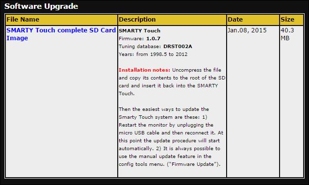
37 As Illustrated below, the SD card will fit into the slot that is located on top of the USB Adaptor. 2.) Plug the Smarty Touch USB Adapter into an open USB port on your Computer and download the Smarty Touch SD Card Image a. Go to smartyresource. b. Click on the Smarty Touch Complete SD Card Image download link under Software Upgrade
38

39 Below are the files that you will see when you open the Smarty Touch SD card image file.
 c.")
40 3.) Drag and copy the contents of this folder into the Smarty Touch SD card. a. Highlight the new content that is included in the latest SD card image that you just downloaded. b. Click and drag the content over on top of the Smarty SD card that should be displayed on the left pane, adjacent to the container that you are viewing the new content in. (See Example Above ) c. A window will come up telling you that there is already a file with the same name in this location. When this shows up, make sure that the bottom left check box that says Do this for the next X conflicts, then select Copy and Replace. (See Example Below) Continue to go through this procedure until all of the files are copied to the SD card.

41 d. When the content finishes copying to the SD card, you are finished. You may bring the SD card to the Smarty Touch and then turn the ignition key on. The Tuner should begin updating automatically. Let this go through and you are finished!
42 . Image of what you should see when you plug the SD card back into the display
43 If it doesn t begin updating automatically: 1.) Go to the Config. Tools menu point, located on the main menu. 2.) Select Firmware Update


44 3.) Select yes to proceed with the update. 4.) The Smarty will begin loading the firmware update. Let this go through and you are finished!
45 #1 in Dodge Cummins Performance THIS IS A HIGH PERFORMANCE PRODUCT USE AT YOUR OWN RISK This product is intended for OFF ROAD USE ONLY This product is not intended to be used to break the law Do not use this product until you have read the following agreement. This agreement sets forth the terms and conditions for the use of this product. The installation of this product indicates that the buyer has read and understands this agreement and accepts the terms and conditions. DISCLAIMER OF LIABILITY Smarty Performance King, it s distributors, jobbers and dealers (hereafter Seller) shall be in no way responsible for the product s proper uses and service. THE BUYER HEREBY WAIVES ALL LIABILITY CLAIMS. The buyer acknowledges that he is not relying on the Sellers skill or judgement to select of furnish goods suitable for any particular purpose and that there are no liabilities which extend beyond the description on the face hereof, and the buyer hereby waivers all remedies or liabilities expressed or implied, arising by law or otherwise ( including without any obligation of the seller with respect fitness, merchantability and consequential damages ) whatever or not occasioned by thesellers negligence. The Seller disclaims any warranty and expressly disclaims any liability for personal injury and damages. The buyer acknowledges and agrees that the disclaimer of any liability for personal injury is a material term for this agreement and the buyer agrees to indemnify the Seller and to hold the Seller harmless from any claim related to the item of the equipment purchased. Under no circumstances will the seller be liable for any damages or expenses by reason of use or sale of any such equipment. The Seller assumes no liability regarding the improper installation or misapplication of its products. It is the installers responsibility to check for proper installation and in doubt contact the manufacturer. The buyer is solely responsible for all warranty issues from the manufacturer. LIMITATION OF WARRANTY Smarty Performance King (Hereafter Seller) gives Limited Warranty as to description, quality, merchantability, and fitness for any particular purpose, productiveness, or any other matter of the Seller s product sold herewith. The Seller shall be in no way responsible for the products proper use and service and the buyer hereby waives all rights other than those expressly written herein. This warranty shall not be extended, altered or varied except to be a written instrument signed by Seller and Buyer. The warranty is limited to one ( 1 ) year from the date of sale and limited solely to the parts contained within the products kit. All products that are in question of warranty must be returned prepaid to the Seller and must be accompanied by a dated proof of purchase receipt. All Warranty claims are subject to approval by Smarty Performance King. Under no circumstances will the Seller be liable for any labour charged or travel time incurred by in diagnosis for defects, removal, or reinstallation of this product or any other contingent expenses. Under no circumstances will the Seller be liable for any damage or expenses incurred by reason of the use or sale of any such equipment. In the event that the buyer does not agree with this agreement: THE BUYER MAY PROMPTLY RETURN THIS PRODUCT, IN A NEW AND UNUSED CONDITION, WITH A DATED PROOF OF PURCHASE TO THE PLACE OF PURCHASE WITHIN TEN (10) DAYS FROM THE DATE OF PURCHASE FOR A FULL REFUND. THE INSTALLATION OF THIS PRODUCT INDICATES THAT THE BUYER HAS READ AND UNDERSTANDS THIS AGREEMENT AND ACCEPTS THE TERMS AND CONDITIONS. Shop for other performance chips & programmers on our website.
Smarty Touch User Guide
 Smarty Touch User Guide Thank you for purchasing the Smarty Touch! We have put a lot of hard work into the production of this tuner, and we sincerely hope you enjoy it. This is a guide that explains most
Smarty Touch Comprehensive Guide
 Smarty Touch Comprehensive Guide Thank you for purchasing the Smarty Touch! We have put a lot of hard work into the production of this tuner, and we sincerely hope you enjoy it. This is a guide that explains
UNLEASH THE POWER. See More at: bullydog.com WITH BULLY DOG PERFORMANCE PRODUCTS. Doc.# BD43569 v1.0.1
 Bully Dog Technologies, LLC is a team built on integrity that is dedicated to leading the vehicle performance industry with an uncompromising code of ethics demonstrated in the soundness of its employees,
6.0L FORD Power Stroke
 6.0L FORD Power Stroke Exhaust Outlook Monitor Intake Modules OPERATING Instructions Thank You & Enjoy! For Free Technical Support Call (208) 397-3200 1 10 REMEMBER THIS IS A PERFORMANCE PRODUCT USE AT
Micro Tuner Model RaceME Pro Common Rail Dodge Ram 6.7L, 24 Valve, Cummins Diesel Engine. Instruction Manual
 Micro Tuner Model RaceME Pro Common Rail Dodge Ram 6.7L, 24 Valve, Cummins Diesel Engine Instruction Manual PLEASE READ THIS ENTIRE INSTRUCTION MANUAL BEFORE PROCEEDING www.racemecanada.com Rev. 1.00A
Smarty. MADS - Micro Tuner model S-06 Common Rail Dodge Ram 5.9L, 24 Valve, Cummins Diesel Engine. Instruction manual
 Smarty - Micro Tuner model S-06 Common Rail Dodge Ram 5.9L, 24 Valve, Cummins Diesel Engine Instruction manual PLEASE READ THIS ENTIRE INSTRUCTION MANUAL BEFORE PROCEEDING www.madselectronics.com Page
R52 Top Commander. Installation and Configuration Guide. 325 Sharon Park Dr. #652. Menlo Park, CA USA (650)
") R52 Top Commander Installation and Configuration Guide 325 Sharon Park Dr. #652 Menlo Park, CA 94025 USA (650) 241-1161 www.fes-auto.com R52 Top Commander Installation Guide Page 2 Table of Contents Chapter
R52 Top Commander Installation and Configuration Guide 325 Sharon Park Dr. #652 Menlo Park, CA 94025 USA (650) 241-1161 www.fes-auto.com R52 Top Commander Installation Guide Page 2 Table of Contents Chapter
user guide read all safety warnings and cautions prior to using this product
 for Android & ios user guide read all safety warnings and cautions prior to using this product Contents 3 Section 1: Safety 3 Warnings & Cautions Explained 3 Safety Warnings 4 Section 2: Product Overview
ngauge Instruction Manual v1.10
 ngauge Instruction Manual v1.10 Table of Contents List of Revisions... 3 Important Notes... 4 Pre-Installation Notice... 5 1 Installation... 5 1.1 Cable Routing... 5 1.2 Attaching Windshield Mount... 5
In order to receive a user name, password and tunes, you must do the following 3 things:
 1 GETTING STARTED In order to receive a user name, password and tunes, you must do the following 3 things: 1. Fill out the disclaimer with all of your info and fax to 828-692-9968 or email it to sales@spartandieseltech.com.
1 Customer. 2 Tuner. SmartyUDCsw - Remote Tuning Guide. 1.1 Customer requirements. 2.1 Tuner requirements
 SmartyUDCsw - Remote Tuning Guide 1 Customer 2 Tuner 1.1 Customer requirements 2.1 Tuner requirements A Smarty device with the latest software revision installed. SmartyUDCsw installed on a PC. SmartyUDCsw
ngauge Instruction Manual v1.14
 ngauge Instruction Manual v1.14 Table of Contents List of Revisions... 3 Important Notes... 4 Pre-Installation Notice... 5 1 Installation... 5 1.1 Cable Routing... 5 1.2 Attaching Windshield Mount... 5
Superchips 1705 MAX MicroTuner Ford Powerstroke 7.3L Turbo Diesel Vehicles Vehicle Programming Instructions
 Page 1 of 12 Form 0126K 10/26/2004 Superchips Inc. Superchips 1705 MAX MicroTuner Ford Powerstroke 7.3L Turbo Diesel Vehicles Vehicle Programming Instructions PLEASE READ THIS ENTIRE INSTRUCTION SHEET
MANUFACTURING LLC Please read this manual carefully before using this product. 360SLT SMARTLINK TM TPMS TABLET USER MANUAL
 MANUFACTURING LLC Please read this manual carefully before using this product. 360SLT SMARTLINK TM TPMS TABLET USER MANUAL INDEX I. INTRODUCTION... 1 1. PACKAGE AND ACCESSORIES... 1 2. START TO USE...
zpen-1080p Features zpen-1080p Layout
 1 zpen-1080p Features CMOS image sensor with Low Light sensitivity HD 1080P up to 30fps, 720P up to 60fps H.264 compression Built-in micro SD card, supports up to 32GB One button operation Easily download
Remote Monitoring and Tracking for High Horsepower Systems. Operator s Manual. gplink.com. Operator s Manual Version 1.3
 Remote Monitoring and Tracking for High Horsepower Systems Operator s Manual Operator s Manual Version 1.3 gplink.com 1 Welcome Aboard Congratulations on the purchase of your gplink system. This operator
DashDAQ Series II. Instruction Manual. Dear Customer,
 Dear Customer, DashDAQ Series II Congratulations! You have just purchased the most powerful, sophisticated, and easy to use automotive data logger ever created. The DashDAQ Series II gives everyone access
MEGA DIAL PANEL Instructions
 2036 Fillmore Street Davenport, Ia. 52804 563-324-1046 www.racedigitaldelay.com MEGA DIAL PANEL Instructions WARRANTY AND DISCLAIMER DIGITAL DELAY ELECTRONICS INC. WARRANTS THE PRODUCTS IT MANUFACTURES
Chapter 1 : FCC Radiation Norm...3. Chapter 2 : Package Contents...4. Chapter 3 : System Requirements...5. Chapter 4 : Hardware Description...
 Table of Contents Chapter 1 : FCC Radiation Norm...3 Chapter 2 : Package Contents...4 Chapter 3 : System Requirements...5 Chapter 4 : Hardware Description...6 Chapter 5 : Charging Your Keychain...7 Chapter
10 Slim Digital Photo Frame Instructional Manual
 10 Slim Digital Photo Frame Instructional Manual aluratek.com mnl M10447 model ASGK410B Copyright 2017 Aluratek, Inc. All Rights Reserved. Table of Contents Frame Features... Frame Control Close-up...
GAP Flasher. For all supported Vehicles. Quick Guide, Version 1.3 Firmware V1.0
 For all supported Vehicles By Quick Guide, Version 1.3 Firmware V1.0 1 1 Introduction This quick guide summarizes the operations needed to update the engine map and or firmware version. Some operations
14 Digital Photo Frame Instructional Manual
 14 Digital Photo Frame Instructional Manual aluratek.com mnl M10423 model ADMPF214B Copyright 2017 Aluratek, Inc. All Rights Reserved. Table of Contents Frame Features... Frame Control Close-up... Remote
Trimble S6 and SPS700 Total Station Firmware
 Trimble S6 and SPS700 Total Station Firmware Release Notes Introduction Upgrading from a previous version Using Trimble S6/SPS700 firmware with other Trimble products New features/enha ncements Changes
Either witech OR StarMOBILE DESKTOP CLIENT can be used to perform this bulletin. FLASH FILES FOR THIS BULLETIN ARE AVAILABLE VIA THE INTERNET.
 NUMBER: 18-020-10 GROUP: Vehicle Performance DATE: June 10, 2010 This bulletin is supplied as technical information only and is not an authorization for repair. No part of this publication may be reproduced,
DataPort 350 & 525 USB 2.0 and FireWire Enclosure User s Guide (800)
") DataPort 350 & 525 USB 2.0 and FireWire Enclosure User s Guide WWW.CRUINC.COM (800) 260-9800 TABLE OF CONTENTS PAGE Package Contents 1 Features and Requirements 2 Installation 6 Trouble Shooting 16 Technical
DataPort 350 & 525 USB 2.0 and FireWire Enclosure User s Guide WWW.CRUINC.COM (800) 260-9800 TABLE OF CONTENTS PAGE Package Contents 1 Features and Requirements 2 Installation 6 Trouble Shooting 16 Technical
64GB USB Flash Drive
 *3rd Party App Required 64GB USB Flash Drive MODEL NUMBER: 78181 USER GUIDE Contents 1. Welcome Section 2. Contents & Features 3. 4. 5. 6. 5-10. 11-13. Connectors Mounting The Flash Drive Accessing Accessing
Introduction & Features. Important Notes. Installation Steps
 Navigation Unlock & Reverse Camera Input Interface for Chrysler/Dodge/Jeep/Ram Vehicles Rev. 051915 ***Only applicable to revision 1.1.2 firmware on BCI-CH21*** Class 2 J1850 VPW Arbitration J1850 Class
MTX-A, Fuel Pressure Gauge PSI
 MTX-A, Fuel Pressure Gauge 0-100 PSI Contents 1 Mounting and Sensor Installation... 2 1.1 Gauge Mounting... 2 1.1.1 Changing the MTX-A s Gauge Bezel... 2 1.2 Fuel Pressure Sensor... 2 2 Wiring... 3 2.1
SaviSign Manager User Manual
 SaviSign Manager User Manual Digital Signage Management Software For The P100 Signage Player For use with Windows 7 or Higher Easy-to-use, powerful software Perfect for crafting digital signage displays!
User Guide. Subaru Turbo (North American Models)
") User Guide Subaru Turbo (North American Models) Page 2 Table of Contents Product Introduction 4 Supported Vehicle List 4 In-Box Contents 5 What Is A Map? 7 AccessPORT Installation 8 Pre-Installation 8
User Guide Subaru Turbo (North American Models) Page 2 Table of Contents Product Introduction 4 Supported Vehicle List 4 In-Box Contents 5 What Is A Map? 7 AccessPORT Installation 8 Pre-Installation 8
Options. Parts List. Optional Expansion Hub Optional Ignition Module Optional Memory Card
 Options Optional Expansion Hub Optional Ignition Module Optional Memory Card View boost, speed, and gear on the LCD Display. View the ignition changes on the LCD Display. Log and store map data. Card storage
Doran 360SL Programming Tool
 Doran 360SL Programming Tool Operations Manual I. INTRODUCTION The Doran 360 tool was designed to work with the Doran 360SL system. This tool is used to program all of the information for the trailer wheel
Woolich Racing. USB ECU Interface User Guide
 Woolich Racing USB ECU Interface User Guide 1) Introduction This user guide covers how to use the Woolich Racing USB ECU Interface. This includes: Connecting the USB ECU Interface into the Bike Harness
Troubleshooting Tips & Procedures. Model 8800 series. GeoNet Wireless
 Troubleshooting Tips & Procedures Model 8800 series GeoNet Wireless No part of this instruction manual may be reproduced, by any means, without the written consent of Geokon. The information contained
DataPort 250 USB 2.0 Enclosure User s Guide (800)
") DataPort 250 USB 2.0 Enclosure User s Guide WWW.CRU-DATAPORT.COM (800) 260-9800 TABLE OF CONTENTS PAGE Package Contents 1 Features and Requirements 2 Installation 4 Trouble Shooting 13 Technical Support
DataPort 250 USB 2.0 Enclosure User s Guide WWW.CRU-DATAPORT.COM (800) 260-9800 TABLE OF CONTENTS PAGE Package Contents 1 Features and Requirements 2 Installation 4 Trouble Shooting 13 Technical Support
TrackCoach ProShift User Guide
 TrackCoach ProShift User Guide For Mini Cooper R50, R52, R53, R55 and R56 325 Sharon Park Blvd. #652 Menlo Park, CA 94025 (650) 241-1161 www.fes-auto.com TrackCoach ProShift User Guide Page 2 READ THIS!
COOP TENDER WI-FI OWNER S MANUAL
 Receive messages from your coop door. Monitor, control and configure your automatic chicken coop door from anywhere in the world with an Internet connection. COOP TENDER WI-FI OWNER S MANUAL 2015 Coop
Digital Electronic Lock OWNER S MANUAL
 CAL-ROYAL CR3000 Digital Electronic Lock OWNER S MANUAL THANK YOU for purchasing CAL-ROYAL CR 3000 Digital Lock. Your new CAL-ROYAL CR3000 Digital Lock advanced features include: 1 Master Code for entry
Track Marshal Software Owner s Manual
 The Leader in Event Critical Timing Electronics Track Marshal Software Owner s Manual for use with RaceAmerica Corner Safety Lights and Black Flag Displays RaceAmerica, Inc. P.O. Box 3469 Santa Clara,
10 Digital Photo Frame Instructional Manual
 10 Digital Photo Frame Instructional Manual aluratek.com mnl M10403 model ADMPF410T Copyright 2016 Aluratek, Inc. All Rights Reserved. Table of Contents Frame Features... Frame Control Close-up... Remote
Duramax 2.8L E98 DSP 4 User Guide. Cindy Myers
 Duramax 2.8L E98 DSP 4 User Guide Cindy Myers Duramax 2.8L E98 DSP 4 User Guide 1998 EFILive Limited All rights reserved First published 29 October 2015 Revised 7 June 2017 EFILive, EFILive FlashScan and
Opazity User Guide Setup, First Use & Advanced Technique
 Opazity User Guide Contents Introduction, T&C 1 Part 1. Installation and Setup 2 Part 2. Instructions for First Use 3 Part 3. Advanced technique: Highlighting areas of a slide at random 6 Appendix: End
Data Acquisition Instructions
 Page 1 of 26 Form DAQ2_A 01/23/2007 Superchips Inc. Superchips flashpaq Data Acquisition Instructions Visit Flashpaq.com for downloadable updates & upgrades to your existing tuner. Page 2 of 26 Form DAQ2_A
OCEANIC SYSTEMS MULTIPLE ENGINE DISPLAY Part Numbers: 4161 USER MANUAL
 OCEANIC SYSTEMS MULTIPLE ENGINE DISPLAY Part Numbers: 4161 USER MANUAL Document revision 1.0.0 2 of 10 1 Introduction... 2 1.1 Product features... 2 2 Unit dimentions... 4 3 Installation... 4 3.1 Unpacking
 SW013 SW013C (Optional 2nd Camera) USER MANUAL WWW.SILENTWITNESS.CO.UK 1 Menu 4 About your SW013 5 Key functions 6 Installing the SW013 07-12 Menu options 13-14 Optional 2nd camera 15 Media playback 15
NCH Software TwelveKeys Music Transcription Software
 NCH Software TwelveKeys Music Transcription Software This user guide has been created for use with TwelveKeys Music Transcription Software Version 1.xx NCH Software Technical Support If you have difficulties
Dynamic Spectrum Tuner Quick Start Guide
 COPYRIGHT The JET DST OBDII Tuner software is copyright 2005 with all rights reserved. The distribution and sale of this software are for the exclusive use of the original purchaser for use exclusively
SafePace 600 Variable Messaging Sign
 SafePace 600 Variable Messaging Sign The new Traffic Logix SafePace 600 variable messaging sign is a versatile and full featured radar speed solution. Whether you want to simply alert drivers of their
Digital Viewer With Multiple Pass Memory Part # 1025
 2036 Fillmore Street Davenport, Ia. 52804 563-324-1046 www.racedigitaldelay.com Digital Viewer With Multiple Pass Memory Part # 1025 WARRANTY AND DISCLAIMER DIGITAL DELAY INC. WARRANTS THE PRODUCTS IT
MTX-A Temperature Gauge User Manual
 MTX-A Temperature Gauge User Manual 1. Installation... 2 1.1 Gauge Mounting... 2 1.2 Temperature Sensor Mounting... 2 1.2.1 Changing the MTX-A s Gauge Bezel... 2 1.3 Main Gauge Wiring... 3 1.3.1 Single
R227. Terms Code Discount per Sales Code Qty Ordered AR-1227
 DSD Business Systems MAS 90/200 Enhancements R227 Terms Code Discount per Sales Code Qty Ordered AR-1227 Version 5.10 2 Terms Code Discount per Sales Code Qty Ordered Information in this document is subject
12 Digital Photo Frame Instructional Manual
 12 Digital Photo Frame Instructional Manual aluratek.com mnl M10208 model ADMPF512F Copyright 2017 Aluratek, Inc. All Rights Reserved. Table of Contents Frame Features... Frame Control Close-up... Remote
INSTRUCTION MANUAL Kingfisher Micro DVR w/ Button Cam SB-MSDVR660
 INSTRUCTION MANUAL Kingfisher Micro DVR w/ Button Cam SB-MSDVR660 Revised: March 15, 2013 Thank you for purchasing from SafetyBasement.com! We appreciate your business. We made this simple manual to help
Lotus DX. sit-stand workstation. assembly and operation instructions. MODEL # s: LOTUS-DX-BLK LOTUS-DX-WHT
 Lotus DX assembly and operation instructions sit-stand workstation MODEL # s: LOTUS-DX-BLK LOTUS-DX-WHT safety warnings 13.6 Kg 30 lbs. 2.2 Kg 5 lbs. safety instructions/warning Read and follow all instructions
ndash Instruction Manual
 ndash Instruction Manual 1 Table Of Contents Installation... 5 Cable Routing... 5 Attaching Windshield Mount... 5 SD Memory Card... 5 Basic Operation... 5 Menu Navigation... 5 New Vehicle Setup/Find Signals...
MWC-8. Operation MWC-8 800MHz Controller Manual. Operation Manual. manmwc9.
 MWC-8 Operation MWC-8 800MHz Controller Manual Operation Manual manmwc9 www.myeclubtv.com 1 CONTENTS Specifications. 3 Controller Orientation (Front / Rear) 4 Keypad Key Identification. 5 Main Features
TLK10081 EVM Quick Start Guide Texas Instruments Communications Interface Products
 TLK10081 EVM Quick Start Guide Texas Instruments Communications Interface Products 1 Board Overview +5 V Adapter Input Connector for voltage monitor board Connector for SMA break-out or FPGA board. Allows
Ludlum Lumic Data Logger Software Manual Version 1.1.xx
 Ludlum Lumic Data Logger Software Manual Version 1.1.xx Ludlum Lumic Data Logger Software Manual Version 1.1.xx Contents Introduction... 1 Software License Agreement... 2 Getting Started... 5 Minimum
D12VRS User Guide AUTOMOTIVE DIGITAL VIDEO RECORDER
 D12VRS User Guide AUTOMOTIVE DIGITAL VIDEO RECORDER WHAT'S INCLUDED D12VR MICRO SD CARD WINDSHIELD BRACKET Car Charger DC POWER CORD USB CABLE USER GUIDE Welcome Thank you for choosing a Whistler product.
DOCKING STATION FOR THE APPLE 13 MacBook
 DOCKING STATION FOR THE APPLE 13 MacBook 2009 THANK YOU Thank you for purchasing the BookEndz Dock for your MacBook Computer. The purpose of the BookEndz Dock is to eliminate the hassles, headaches, wear
LCD MODULE INSTRUCTIONS
 LCD MODULE INSTRUCTIONS Overview: The LCD Module is an optional module that allows live data to be displayed right in your vehicles dash. It is completely customizable and shows 10 separate channels of
General Notice Introduction Functional Description Product Troubleshooting Driver Setup...
 Table of Contents General Notice... 1 Introduction... 2 Functional Description... 4 Product Troubleshooting... 7 Driver Setup... 8 Firmware Update... 10 Warranty and Service... 12 General Notice The Bluetooth
APPLICATION NOTE. Application Note: 4D-AN-P4007. ViSi-Genie Play Video. Document Date: November 15 th, Document Revision: 1.
 APPLICATION NOTE Application Note: ViSi-Genie Play Video Document Date: November 15 th, 2012 Document Revision: 1.0 Description This Application Note explores the possibilities provided by ViSi-Genie for
50 % fewer steps to resolution
 A Principled Technologies report: Hands-on testing. Real-world results. Get ahead of the problem by choosing Dell Premium Support Plus with SupportAssist technology The proactive service plan saved time
What s in the box. SUP paddle sensor. Paddle sensor mounting track. Charger. USB cable. In your Motionize SUP kit you will find:
 User's Manual 1 What s in the box In your Motionize SUP kit you will find: SUP paddle sensor Paddle sensor mounting track Charger USB cable 2 Android & ios Requirements Android 5 or newer. iphone 5 or
TRF-ZW1 Z-Wave Extender. Owner s Manual
 TRF-ZW1 Z-Wave Extender Owner s Manual TRF-ZW1 Z-Wave Extender Owner's Manual 2014 Universal Remote Control, Inc. The information in this Owner s Manual is copyright protected. No part of this manual may
FieldServer X-25 Start-Up Guide
 Sierra Monitor Company FieldServer X-25 Start-Up Guide APPLICABILITY & EFFECTIVITY Effective for all systems manufactured after April 2013 Kernel Version: 6.10 Document Revision: 0 FieldServer FS-X25 Start-Up
WakeboardPro for DBW Engines Graphics Display. User Manual
 WakeboardPro for DBW Engines Graphics Display User Manual January 2006 Table of Contents Page No. Section 1 Using WakeboardPro 1 Wakeboard Speed Mode 1 Adjustable Parameters KDW, NN 2 Section 2 Using RPM
INDEX. Vehicle Integration Canbus System
 INDEX Update Alert: Firmware updates are posted to the web on a regular basis. We recommend you check for firmware and/or install guide updates prior to installation of this product. Page to 7 XKLINT:
EFILive AutoCal Information for End Users
 EFILive AutoCal Information for End Users Cindy Myers EFILive AutoCal Information for End Users 2010 EFILive Limited All rights reserved First published 01 July 2010 Revised 7 June 2017 EFILive, EFILive
Oracle. Field Service Cloud Configuring and Using Reports 18B
 Oracle Field Service Cloud 18B Part Number: E94743-02 Copyright 2018, Oracle and/or its affiliates. All rights reserved Authors: The Field Service Cloud Information Development Team This software and related
Installing Your Microsoft Access Database (Manual Installation Instructions)
") Installing Your Microsoft Access Database (Manual Installation Instructions) Installation and Setup Instructions... 1 Single User Setup... 1 Multiple User Setup... 2 Adjusting Microsoft Access 2003 Macro
Installing Your Microsoft Access Database (Manual Installation Instructions) Installation and Setup Instructions... 1 Single User Setup... 1 Multiple User Setup... 2 Adjusting Microsoft Access 2003 Macro
OBDII Programmer Quick Start Guide
 COPYRIGHT The C.A.T.S. OBDII Programmer is copyright 2005 with all rights reserved. The distribution and sale of this software are for the exclusive use of the original purchaser for use exclusively on
PocketWeave User s Manual
 PocketWeave User s Manual Version 1.1 Written by Kriston M. Bruland AVL Looms 3851 Morrow Lane, Suite #9 Chico, CA 95928-8305 U.S.A. 530 893-4915 530 893-1372 (fax #) info@avlusa.com (e-mail) www.avlusa.com
Digital Contact Tachometer
 Digital Contact Tachometer Item 66400 Read this material before using this product. Failure to do so can result in serious injury. SAVE THIS MANUAL. When unpacking, make sure that the product is intact
MPE5 Scouting Camera Instruction Manual.
 MPE5 Scouting Camera Instruction Manual. Page1 Table of Contents Button function diagram... 3 Introduction... 4 Installing the batteries... 4 Installing the SD card... 5 Setting the camera options... 6
PRO ESC - LCD PROGRAM CARD USER MANUAL. The Fantom FR-10 PRO LCD Program Card only applies to the FR-10 PRO 1:10 scale, 2S, 160A brushless ESC.
 PRO ESC - LCD PROGRAM CARD USER MANUAL The Fantom FR-10 PRO LCD Program Card only applies to the FR-10 PRO 1:10 scale, 2S, 160A brushless ESC. The LCD Program Card can be used in two ways as follows: 1.
12/2013. Installation Guide & User Manual
 12/2013 Installation Guide & User Manual ABOUT THIS MANUAL This manual has been written to help you understand all the functions and capabilities of the Yamaha Snowmobile Diagnostic Tool in order to gain
CarDAQ-M J2534-1&2 Module Quick Start Guide
 CarDAQ-M J2534-1&2 Module Quick Start Guide CarDAQ-M has been carefully designed and tested to comply with OBDII protocols, which are used on most 1996 and newer cars and light trucks sold in the USA.
hp l1619a smart attachment module
 hp l1619a smart attachment module user s guide Smart Attachment Module 1 Notice This manual and any examples contained herein are provided as is and are subject to change without notice. Hewlett-Packard
RVU - Update Programming For Catalytic Converter System (IC)
") 26 07 01 May 11, 2007 2010066/3 Supersedes Technical Service Bulletin Group 26 number 05-03 dated July 20, 2005 due to addition of Saga warranty data, change in VIN range, and reformatting RVU - Update
26 07 01 May 11, 2007 2010066/3 Supersedes Technical Service Bulletin Group 26 number 05-03 dated July 20, 2005 due to addition of Saga warranty data, change in VIN range, and reformatting RVU - Update
Hardware Documentation
 Hardware Documentation for JTAG Debug Adapter Version 1.0 2014-12-02 F&S Elektronik Systeme GmbH Untere Waldplätze 23 D-70569 Stuttgart Fon: +49(0)711-123722-0 Fax: +49(0)711 123722-99 History Date V Platform
FORD TAURUS 2010 CANMAX400DEI-LINCOLN1. Push-to-start INDEX PARTS REQUIRED BUT NOT INCLUDED:
 CANMAX00DEI-LINCOLN FORD TAURUS 00 Rev.: 000 Page CANMAX00DEI supports multiple data bus architectures including: CAN High speed, CAN Single Wire, CAN Fault Tolerant, GM-LAN, J850, ISO, BEAN, FLEXRAY and
SD1306. Speed Dome IP Camera. Quick User Guide
 SD1306 Speed Dome IP Camera Quick User Guide Table of Contents I. Camera Introduction... 1 1. Package Contents... 1 2. Hardware Installation... 2 2.1 Factory Default... 6 3. SD card Compatibility List...
EagleEye 4: 3-4 Cam Dashcam GPS Dash System Instructional Manual
 EagleEye 4: 3-4 Cam Dashcam GPS Dash System Instructional Manual Thank you for purchasing our dash camera, we develop this product based on the difficulty of proving innocence if involved in a traffic
Quad-Pole Magnet Actuator User s Manual
 Quad-Pole Magnet Actuator User s Manual Integral Solutions Int'l Version 1.1.3 Phone: (408) 653-0300 Fax: (408) 653-0309 Copyright 2010 Integral Solutions Int'l All rights reserved Integral Solutions Int'l
PR301 FM/AM Pocket Radio USER MANUAL IMPORTANT! WARRANTY INFORMATION INSIDE. PLEASE READ. Trademark of TEAC Corporation JAPAN
 PR301 FM/AM Pocket Radio USER MANUAL IMPORTANT! WARRANTY INFORMATION INSIDE. PLEASE READ Trademark of TEAC Corporation JAPAN www.teac.com.au WARRANTY REGISTRATION Please keep this information for your
SUPRARAM 500RX OPERATOR S MANUAL
 SUPRARAM 500RX OPERATOR S MANUAL Congratulations on purchasing the high-performance SupraRAM 500RX for the Amiga 500. The SupraRAM 500RX lets you add up to 8MB of FAST RAM to your system, allowing you
Made in U.S.A. 1
 Made in U.S.A. www.smartavi.com 1 1-800-AVI-2131 TABLE OF CONTENTS INTRODUCTION & FEATURES 2 Getting Started and Installation 3 Start-Up 4 Managing Streams and Environment 5 Frequently Asked Questions
Delta Unifence Kit Installation Instructions
 Delta Unifence Kit Installation Instructions Please note this installation kit is designed for installation on the Delta Commercial Unifence (units made between 1993 and current). Accurate Technology manufactures
Multiple Users Accessing the Same Chassis
 SmartBits Multiport Port/Stream/Performance Analysis System Application Note #27 Multiple Users Accessing the Same Chassis July 2000 P/N 340-1113-001 REV A Netcom Systems, Inc. (800) 886-8842 Toll Free
ImageMate 12-in-1 Reader/Writer User Guide
 ImageMate 12-in-1 Reader/Writer User Guide Model Number SDDR-89 Product Description The Multi-Function Hi-Speed USB 2.0 Reader/Writer CompactFlash Type I/II, SD TM, minisd TM, MultiMediaCard TM, RS-MMC
LLTOUCHDX4 - PRODUCT INFORMATION
 TOUCH DX4 RGBW WALL MOUNTED CONTROLLER The Touch DX4 is designed for RGBW products and features 4x4A output up to 16A. Easy selection of colour using the touch sensitive colour circle. You can also control
TOUCHBOX. iphone I N S T R U C T I O N M A N U A L
 TOUCHBOX W I R E L E S S C O N T R O L L E R iphone I N S T R U C T I O N M A N U A L Thank you for purchasing TouchBox by ZAETECH. Disclaimer TouchBox is for show and off road use only. It may not be
NAPCO iseevideo Fixed IP Camera User Guide
 333 Bayview Avenue Amityville, New York 11701 For Sales and Repairs, (800) 645-9445 For Technical Service, (800) 645-9440 Publicly traded on NASDAQ NAPCO 2008 R Symbol: NSSC NAPCO iseevideo Fixed IP Camera
Owner s s Manual. SATA A II LCD Hot-Swap Systems. Macintosh, Windows, Linux EXTERNAL SYSTEM INTERNAL 5.25 SYSTEM DUAL EXTERNAL SYSTEM
 Owner s s Manual SATA A II LCD Hot-Swap Systems EXTERNAL SYSTEM INTERNAL 5.25 SYSTEM DUAL EXTERNAL SYSTEM Macintosh, Windows, Linux SATA (Serial ATA) Hot-Swap Drive System / Case Kit Table of Contents
Professional Jukebox Software
 Professional Jukebox Software Exclusively distributed by Contents Security devices Page 3 The Load program Page 4 Music encryption Page 5 Splash screen Page 6 Main screen Page 7 Button Mode Page 8 Selecting
Instruction Manual. Balanced Audio Upgrade Installation. iport IW-21/IW-22 Upgrade Kits. Balanced Audio Upgrade Kit. (iport IW-21)
") Introduction The iport IW Balanced Audio, Balanced Video, and RS-232 Upgrade Kits add functionality and capability to iport IW-21 and IW-22 models. Balanced Audio Upgrade Kit For use with iport IW-21 models.
Introduction The iport IW Balanced Audio, Balanced Video, and RS-232 Upgrade Kits add functionality and capability to iport IW-21 and IW-22 models. Balanced Audio Upgrade Kit For use with iport IW-21 models.
zclock-200w User Manual
 zclock-200w User Manual Table of contents Product Diagram......Page 1 Alarm clock operation......page 5 Setting up Hidden Cam.....Page 7 Advanced set up......page 14 Windows......Page 15 Apple OSX...Page
Getting Started With the CCPilot VI and QuiC
 Page 1 of 24 Getting Started With the CCPilot VI and QuiC Page 2 of 24 Table of Contents Purpose... 3 What You Will Need... 4 Install the QuiC Tool... 6 Install the QuiC Runtime... 7 Basics of the QuiC