2012 ACCESS CONTROL PROXIMITY KEYPAD FINGERPRINT BLUETOOH RADIO FREQUENCY COMBINED
|
|
|
- Lizbeth Polly Ramsey
- 5 years ago
- Views:
Transcription


1 01 ACCESS CONTROL PROXIMITY KEYPAD FINGERPRINT BLUETOOH RADIO FREQUENCY COMBINED

2

3 INDEX QUICK GUIDE 0 STAND-ALONE 04 CENTRALIZED 36 ACCESSORIES 86 INDEX OF REFERENCES 94


4 QUICK GUIDE OF REFERENCES KEYPAD Cityline Skyline Cityline CL Marine Loft STAND-ALONE MDS/CAC CENTRALISED x PROXIMITY Cityline Skyline Cityline CL Marine Loft STAND-ALONE MDS/CAC CENTRALISED x WG-6/DATACLOCK CENTRALIZED FINGERPRINT Cityline Skyline Marine STAND-ALONE MDS/CAC CENTRALISED x x x WG-6/DATACLOCK CENTRALIZED Access Control


5 COMBINED Keypad+Fingerp. Proxi+keypad City Classic Proxi+Keypad Loft Proxi+Keypad STAND-ALONE 6996 x x x MDS/CAC CENTRALISED x x WG-6/DATACLOCK CENTRALIZED BLUETOOTH Cityline Skyline Marine Mini STAND-ALONE MDS/CAC CENTRALISED x x x x WG-6/DATACLOCK CENTRALIZED RADIO FREQUENCY Dual channel RF trinary emitter Digital RF emitter Dual RF emitter Garage receiver Monochannel receiver DIN rail receiver Villa receiver STAND-ALONE MDS/CAC CENTRALISED x x x x Emitters Receivers 011 Access Control 3
6
7 STAND-ALONE ACCESS CONTROL

8 STAND-ALONE Stand-alone systems are recommended for buildings requiring basic access control, without the need for an incidents register. It can also be used as an add on to an electronic or video doorentry system and allows residents access to buildings, to offices and garages. The system manages access through one door and is characterised by its easy installation and programming (activating and deactivating users). If it is necessary to control several doors, a stand-alone access control can be installed on each one, with each user having a single identity to access all doors. If you want to give one sole user access through one door, activate their identifier on the corresponding reader. If you want to prevent access you can delete it from the machine's memory. In this simple way, you can create a policy of restriction by zones. Stand-alone access control systems are also known as CLASS I access control Access Control


 and the receiver. Bluetooth BLUETOOTH.")

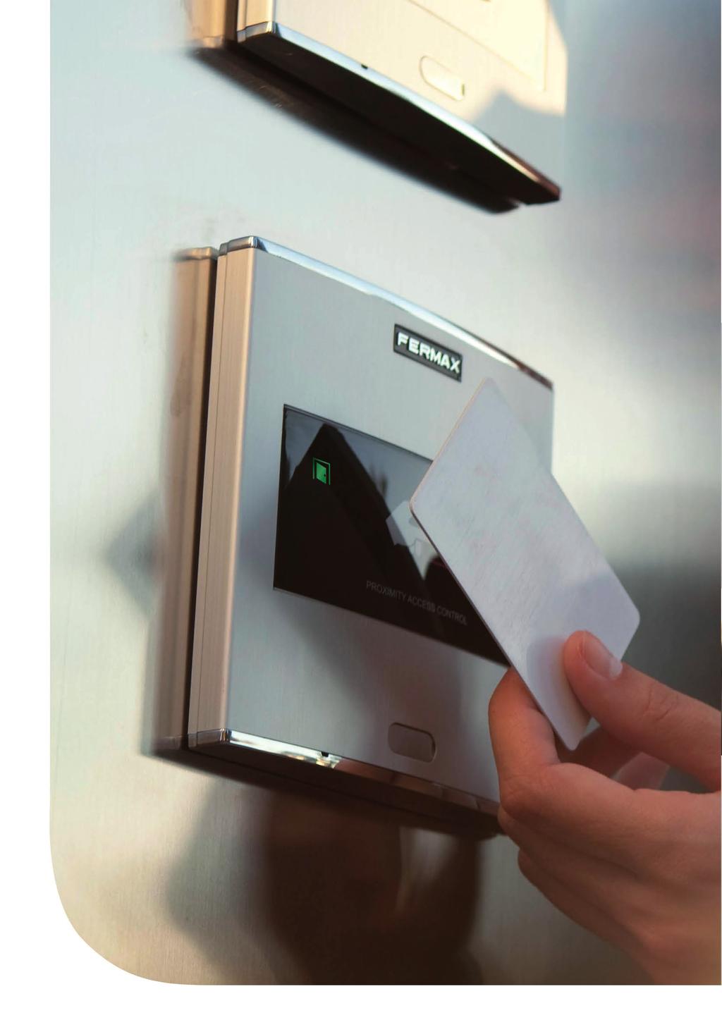
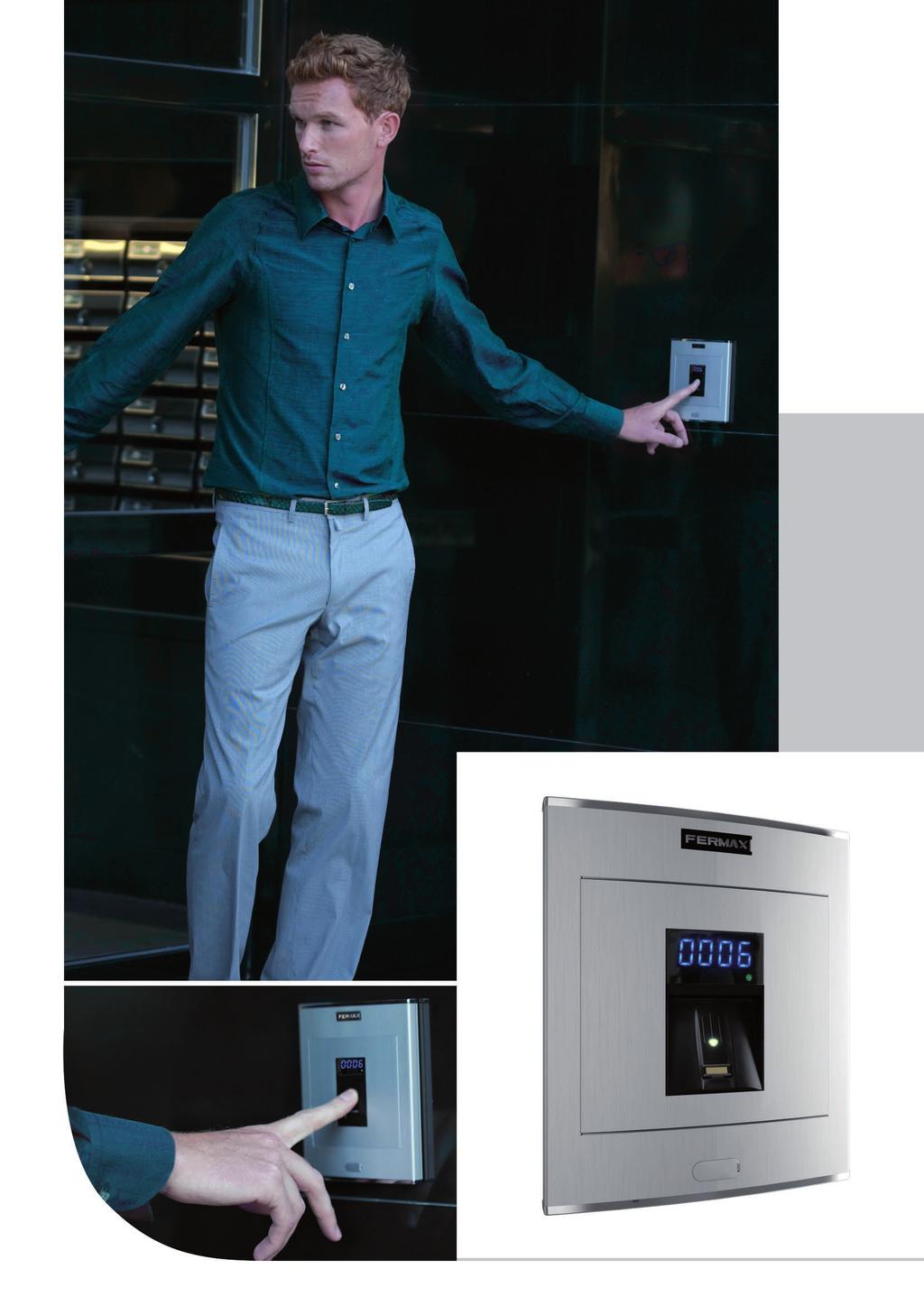
9 There are several types of technology, depending on the interaction between the identifier and the reader. KEYPAD. The user should enter a code on the keypad. It is the most economical model as it does not use identifiers. The same code can be used by various users. Keypad PROXIMITY. The identifier is a card (similar to a credit card) or a proximity keyring. The identifier is swiped by the reader at a distance of several centimetres. The reading is facilitated by means of radio frequency data transmission. Proximity Reader RADIO FREQUENCY. This technology is mainly used in garage accesses given the flexibility allowed by the large distance between the identifier (control) and the receiver. Bluetooth BLUETOOTH. Access control functions by using mobile phones with Bluetooth technology. The telephone system itself identifies the user. The advantage of this system is the reader's operating distance, which makes it very useful for vehicle and pedestrian access. BIOMETRIC FINGERPRINT. Biometric fingerprint access reader with sensor. Identifies the user by their fingerprint (feature which is unrepeatable and unique to each person), offering a greater level of security than any other system using another type of identifier. Fingerprint 011 Access Control 7
 or surface installation (ref.7061, optional). Recommended for interiors and exteriors.")
10 STAND-ALONE Keypad Cityline Memokey Ref.6991 Access control keypad which allows the door to be opened when a pre-programmed code of up to 6 digits is entered. Capacity: up to 100 user codes. Length 4 to 6 digits. Integrated within the Cityline aluminum panel. Flush mounted (ref.8948, including box) or surface installation (ref.7061, optional). Recommended for interiors and exteriors. Reader and controller integrated within the same module. Acoustic confirmation tone which sounds when a button is pressed. Acoustic and visual confirmation with LEDs showing if a code has been accepted/rejected. Blue backlit zamak keypad with status LED. A relay lock-release activation (NA, NC). Programmable between 1 and 99 secs or bistable. Exit button input. Free access button input (trades). Auxiliary Open Collector Output (150mA max) to indicate a vandalism attempt or open/forced door. Each code can activate relays at the same time. The keypad is located in the exterior area. The rest of the devices are connected to this module and installed in the building's interior: power supply and lock-release. An exit button can be used optionally. 30Vac PROGRAMMING Power Supply Programming from the same keypad using a master code. Lock-Releases Ref.6991 Exit Button SPECIFICATIONS Dimensions: * Reader * Flush Mounted Box * Surface Box Environmental Protection (IP) Anti-Shock Protection (IK) Power Supply (V) Consumption (ma) s/lock-release Operating Temperature 130x18 115x114x45 130x18x V (ac/dc) 40/110-15º to 55º C References Normal Reinforced 1Vdc 1Vac * Door lock recommended. Dimensions: (horizontal)x(vertical)x(depth) mm Access Control
11 STAND-ALONE Keypad W Skyline Memokey Ref.7438 Access control keypad module to be installed on Skyline audio/video door entry system panels. Lock release on entering a code with up to 6 preprogrammed digits. Capacity: up to 100 user codes. Length 4 to 6 digits. Blue backlit zamak keypad with status LEDs. Recommended for interior and exterior use. Reader and controller integrated within the same module. Acoustic confirmation tone which sounds when a button is pressed. Acoustic and visual confirmation with LEDs showing if a code has been accepted/ rejected. A relay lock-release activation (NA, NC). Programmable from 1 and 99 seconds or bistable. Exit button input. Free access button input (trades). Auxiliary Open Collector Output (150mA max) to indicate a vandalism attempt or open/forced door. Each code can activate relays at the same time. The electronic or video door entry system panels are located in the building's exterior. The panel can be configured in an intuitive manner using the memokey module for greater ease of use and access security. The rest of the devices are connected to this module and installed in the building's interior: power supply and lock-release. An exit button can be used optionally. PROGRAMMING 30Vac Programming from the same keypad using a master code. Power Supply SPECIFICATIONS Lock-Releases Ref Reader Dimensions 105,x95 Exit Button Environmental Protection (IP) 54 * Anti-Shock Protection (IK) Power Supply (V) Consumption (ma) s/lock-release Operating Temperature 07 1V (ac/dc) 40/110-15º to 55º C References Normal Reinforced 1Vdc 1Vac * Door lock recommended. Dimensions: (horizontal)x(vertical)x(depth) mm 011 Access Control 9
12 STAND-ALONE Keypad City Classic Memokey Ref.3610 Access control keypad which allows the door to be opened when a pre-programmed code of up to 6 digits is entered. Capacity: up to 100 user codes. Length 4 to 6 digits. Integrated within an aluminum City Classic panel. Flush mounted (ref.8948, including box) or surface installation (ref.8951, optional). Recommended for interior and exterior use. Reader and controller integrated within the same module. Confirmation tone when a button is pressed or to indicate that the code entered has been accepted/ rejected. A relay lock-release activation (NA, NC). Programmable at from 1 and 99 seconds or bistable. Exit button input. Free access button input (trades). Auxiliary Open Collector Output (150mA max) to indicate a vandalism attempt or open/forced door. Each code can activate relays at the same time. The keypad is located in the exterior area. The rest of the devices are connected to this module and installed in the building's interior: power supply and lock-release. An exit button can be used optionally. PROGRAMMING Programming from the same keypad using a master code. 30Vac Power Supply SPECIFICATIONS Ref.3610 Dimensions: * Reader 130x18 Lock-Releases Exit Button * Flush Mounted Box 115x114x45 * Surface Box 130x18x33 Environmental Protection (IP) 43 * Anti-Shock Protection (IK) Power Supply (V) Consumption (ma) s/lock-release Operating Temperature 07 1V (ac/dc) 6/60 0º to 70º C References Normal Reinforced 1Vdc 1Vac * Door lock recommended. Dimensions: (horizontal)x(vertical)x(depth) mm Access Control
. Auxiliary Open Collector Output (150mA max) to indicate a vandalism attempt or open/forced door. Each code can activate relays at the same time.")
13 STAND-ALONE Keypad City Classic CR Memokey Ref Ref.361 A relay lock-release activation (NA, NC). Programmable at from 1 and 99 seconds or bistable. Exit button input. Free access button input (trades). Auxiliary Open Collector Output (150mA max) to indicate a vandalism attempt or open/forced door. Each code can activate relays at the same time. Access control keypad which allows the door to be opened when a pre-programmed code of up to 6 digits is entered. Capacity for up to 100 user codes. Length 4 to 6 digits. Confirmation tone sounds when a button is pressed and to indicate if the code entered has been accepted/rejected. Reader (ref.360) and controller (ref.361) in two independent modules. The controller is installed in the building's interior near the power supply and lock-release. The metallic box is included with the controller. Flush mounted (ref.8948, including box) or surface installation (ref.8951, optional). A second keypad CR can be added in the building's interior. Maximum distance between reader and controller of 100m. Reader and controller not integrated within the same module. The CR keypad is located in the exterior of the building and is connected to the controller in the interior in the same way as the rest of the device (power supply and lock-release). An exit button can be used optionally. PROGRAMMING Programming from the same keypad using a master code. Ref Vac Power Supply SPECIFICATIONS Dimensions: 6 Ref.361 Exit Button * Reader * Flush Mounted Box 130x18 115x114x45 Lock-Releases * Surface Box 130x18x33 * Metallic Box 154x03x50 Environmental Protection (IP) * Anti-Shock Protection (IK) Power Supply (V) Consumption (ma) s/lock-release Operating Temperature V (ac/dc) 6/60 0º to 70º C References Normal Reinforced 1Vdc 1Vac * Door lock recommended. Dimensions: (horizontal)x(vertical)x(depth) mm 011 Access Control 11
 or surface installation (ref.4701, optional).")
14 STAND-ALONE Keypad Marine Memokey Ref.4699 Access control keypad which allows the door to be opened when a pre-programmed code of up to 6 digits is entered. Capacity: up to 100 user codes. Length 4 to 6 digits. Integrated within a.5mm stainless steel Marine panel. Flush mounted (ref.4641, including box) or surface installation (ref.4701, optional). Recommended for interior and exterior use. Reader and controller integrated within the same module. Acoustic confirmation tone which sounds when a button is pressed. Acoustic and visual confirmation with LED s showing if a code has been accepted/ rejected. Blue backlit zamak keypad with status LEDs. A relay lock-release activation (NA, NC). Programmable at from 1 and 99 seconds or bistable. Exit button input. Free access button input (trades). Auxiliary Open Collector Output (max. 150mA) to indicate a vandalism attempt or open/forced door. Each code can activate relays at the same time. The keypad is located in the exterior area. The rest of the devices are connected to this module and installed in the building's interior: power supply and lock-release. An exit button can be used optionally. 30Vac Power Supply PROGRAMMING Programming from the same keypad using a master code. Lock-Releases Ref.4699 Exit Button SPECIFICATIONS Dimensions: * Reader * Flush Mounted Box * Surface Box Environmental Protection (IP) Anti-Shock Protection (IK) Power Supply (V) Consumption (ma) S/lock-release. Operating Temperature Dimensions: (horizontal)x(vertical)x(depth) mm 150x x160x55 154x184x V (ac/dc) 40/110-15º to 55º C References Normal Reinforced 1Vdc 1Vac * Door lock recommended Access Control

15 STAND-ALONE Keypad Loft Memokey Ref.4540 Access control keypad which allows the door to be opened when a pre-programmed code of up to 6 digits is entered. Membrane keypad finished in texturised ABS plastic with status LEDs. Surface installation. Capacity: up to 100 user codes. Length 4 to 6 digits. Recommended for interior use. Includes 50cm of wiring. Reader and controller integrated within the same module. Acoustic confirmation tone which sounds when a button is pressed. Acoustic and visual confirmation with LED s showing if a code has been accepted/ rejected. A relay lock-release activation (NA, NC). Programmable at from 1 and 99 seconds or bistable. Exit button input. Free access button input (trades). Auxiliary Open Collector Output (max. 150 ma) to indicate a vandalism attempt or open/forced door. Tamper proof to indicate vandalism attempts. The keypad is located in the exterior area. The rest of the devices are connected to this module and they are installed in the building's interior: power supply and lockrelease. An exit button can be used optionally. 30Vac Power Supply PROGRAMMING Programming from the same keypad using Ref.4540 a master code. Lock-Releases Exit Button SPECIFICATIONS Dimensions: * Reader * Flush Mounted Box * Surface Box Environmental Protection (IP) Anti-Shock Protection (IK) Power Supply (V) Consumption (ma) s/lock-release. Operating Temperature Dimensions: (horizontal)x(vertical)x(depth) mm 60x130x3 Not required Not required V (ac/dc) 0/70 0º to 70º C References Normal Reinforced 1Vdc 1Vac * Door lock recommended. 011 Access Control 13
16 STAND-ALONE Proximity Cityline Private Ref.699 Does not require physical contact. 5cm (card) or 1.5cm (keyring) reading distance. Acoustic and visual status data. Status LEDs (help in programming and determining status). Manual programming (using master card or keyring) or via PC software (card activation/deactivation). Door sensor and exit button control. Relay output. Relay lock-release activation with programmable time. Programmable from 1 to 99 seconds. Access control reader which allows the door to be opened by swiping the proximity card or keyring. Only authorised cards or keyrings activate the device. Physical contact is not necessary. Integrated within the Cityline aluminum panel. Flush mounted (ref.8948, including box) or surface installation (ref.7061, optional). Recommended for interior and exterior use. Reader and controller integrated within the same module. Can operate as a stand-alone or centralised system. Configurable between dipswitches (SW). Configuration as a STAND-ALONE system: Capacity: up to 400 user cards or keyrings. Acoustic and visual confirmation using LEDs which advise if the card swiped has been accepted/rejected. The reader is located in the exterior area. The rest of the devices are connected to this module and they are installed in the building's interior: power supply and lock-release. An exit button can be used optionally. PROGRAMMING This can be done in 3 ways: Master card: The first time the power supply is connected, the system waits for a proximity card to be swiped. This is then considered the "master card". Keypad: Recommended if we want to deactivate faulty cards. PC Software: For managing user activation/ deactivations. The WINPROX software can be downloaded from IDENTIFIERS Card without magnetic strip (ref.3361);. Card with magnetic strip (ref.336); 3. Proximity keyring (ref.44501). Lock-Releases SPECIFICATIONS Dimensions: * Reader * Flush Mounted Box * Surface Box Environmental Protection (IP) Anti-Shock Protection (IK) Power Supply (V) Consumption (ma) S/lock-release Operating Temperature Dimensions: (horizontal)x(vertical)x(depth) mm 130x18 115x114x45 130x18x V (ac/dc) 90-15º to 55ºC Ref Vac Power Supply Exit Button References Normal Reinforced 1Vdc 1Vac * Door lock recommended Access Control
17 STAND-ALONE Proximity V Skyline Private Ref.7440 Does not require physical contact. 5cm (card) or 1.5cm (keyring) reading distance. Acoustic and visual status data. Status LEDs (help in programming and determining status). Manual programming (using master card or keyring) or via PC software (card activation/deactivation). Door sensor and exit button control. Relay output. Relay lock-release activation with programmable time. Programmable at 1 to 99 secs. PROGRAMMING This can be done in 3 ways: Master card: The first time the power supply is connected, the system waits for a proximity card to be swiped. This is then considered the "master card". Keypad: Recommended if we want to deactivate faulty cards. PC Software: For managing user activation/ deactivations. The WINPROX software can be downloaded from Access control reader which allows the door to be opened by swiping the proximity card or keyring. Only authorised cards or keyrings activate the device. Physical contact is not necessary. Access control module to be integrated within Skyline audio/video door entry system panels. Recommended for interior and exterior use. Reader and controller integrated within the same module. Can operate as a stand-alone or centralised system. Configurable between dipswitches (SW). Configuration as a STAND-ALONE system: Capacity: up to 400 user cards or keyrings. Acoustic and visual confirmation using LEDs which advise if the card swiped has been accepted/ rejected. The electronic or video door entry system panels are located in the building's exterior. The panel can be configured in an intuitive manner using the private module for greater ease of use and access security. The rest of the devices are connected to this module and they are installed in the building's interior: power supply and lock-release. An exit button can be used optionally. 30Vac Power Supply Exit Button Lock-Releases Ref.7440 IDENTIFIERS Card without magnetic strip (ref.3361);. Card with magnetic strip (ref.336); 3. Proximity keyring (ref.44501). SPECIFICATIONS Reader Dimensions: Environmental Protection (IP) Anti-Shock Protection (IK) Power Supply (V) Consumption (ma) S/lock-release Operating Temperature Dimensions: (horizontal)x(vertical)x(depth) mm 105.X V (ac/dc) 90-15º to 55ºC References Normal Reinforced 1Vdc 1Vac * Door lock recommended. 011 Access Control 15
 or via PC software (card activation/deactivation). Door sensor and exit button control. Relay output.")
18 STAND-ALONE Proximity City Classic Private Ref.347 Does not require physical contact. 3cm (card) or 1cm (keyring) reading distance. Acoustic and visual status data. Manual programming (using master card or keyring) or via PC software (card activation/deactivation). Door sensor and exit button control. Relay output. Relay lock-release activation with programmable time. Programmable from 1 to 99 seconds. Status LEDs (help in programming and determining status). PROGRAMMING This can be done in 3 ways: Master card: The first time the power supply is connected, the system waits for a proximity card to be swiped. This is then considered the "master card". Keypad: Recommended if we want to deactivate faulty cards. PC Software: For managing user activation/ deactivations. The WINPROX software can be downloaded from Access control reader which allows the door to be opened by swiping the proximity card or keyring. Only authorised cards or keyrings activate the device. Physical contact is not necessary. Capacity: up to 400 user cards or keyrings. Integrated within the City Classic aluminum panel. Flush mounted (ref.8948, including box) or surface installation (ref.8951, optional). Recommended for interior and exterior use. Reader and controller integrated within the same module. Acoustic and visual confirmation using LEDs which advise if the card presented has been accepted/rejected. The reader is located in the exterior area. The rest of the devices are connected to this module and they are installed in the building's interior: power supply and lock-release. An exit button can be used optionally. 30Vac Power Supply Ref.347 Exit Button Lock-Releases SPECIFICATIONS IDENTIFIERS Card without magnetic strip (ref.3361);. Card with magnetic strip (ref.336); 3. Proximity keyring (ref.44501). Dimensions: * Reader * Flush Mounted Box * Surface Box Environmental Protection (IP) Anti-Shock Protection (IK) Power Supply (V) Consumption (ma) S/lock-release Operating Temperature Dimensions: (horizontal)x(vertical)x(depth) mm 130x18 115x114x45 130x18x V (ac/dc) 80/10 0º to 60ºC References Normal Reinforced 1Vdc 1Vac * Door lock recommended Access Control
19 STAND-ALONE Proximity Marine Private Ref.547 Access control reader which allows the door to be opened by swiping the proximity card or keyring. Only authorised cards or keyrings activate the device. Physical contact is not necessary. Integrated within a.5mm Marine stainless steel panel. Flush mounted (ref.4641, including box) or surface installation (ref.4701, optional). Recommended for interior and exterior use. Reader and controller integrated within the same module. Can operate as a stand-alone or centralised system. Configurable between dipswitches (SW). Does not require physical contact. 4cm (card) or 1cm (keyring) reading distance. Acoustic and visual status data. Manual programming (using master card or keyring) or via PC software (card activation/deactivation). Door sensor and exit button control. Relay output. Relay lock-release activation with programmable time. Programmable from 1 to 99 seconds. Status LEDs (help in programming and determining status). PROGRAMMING This can be done in 3 ways: Master card: The first time the power supply is connected, the system waits for a proximity card to be swiped. This is then considered the "master card". Keypad: Recommended if we want to deactivate faulty cards. PC Software: For managing user activations/ deactivations. The WINPROX software can be downloaded from IDENTIFIERS Card without magnetic strip (ref.3361);. Card with magnetic strip (ref.336); 3. Proximity keyring (ref.44501). Configuration as a STAND-ALONE system: Capacity: up to 400 user cards or keyrings. Acoustic and visual confirmation using status LEDs which advise if the card swiped has been accepted/ rejected. The reader is located in the exterior area. The rest of the devices are connected to this module and installed in the building's interior: power supply and lock-release. An exit button can be used optionally. Lock-Releases SPECIFICATIONS Dimensions: * Reader * Flush Mounted Box * Surface Box Environmental Protection (IP) Anti-Shock Protection (IK) Power Supply (V) Consumption (ma) S/lock-release Operating Temperature Dimensions: (horizontal)x(vertical)x(depth) mm 150x x160x55 154x184x V (ac/dc) 90-15º to 55ºC 30Vac Ref.547 Power Supply Exit Button References Normal Reinforced 1Vdc 1Vac * Door lock recommended. 011 Access Control 17

20 STAND-ALONE Proximity Loft Private Ref.4530 Access control reader which allows the door to be opened by swiping the proximity card or keyring. Only authorised cards or keyrings activate the device. Physical contact is not necessary. Capacity: up to 400 user cards or keyrings. Module finished in textured ABS plastic. Surface installation. Recommended for interior use. Includes 50 cm of wiring. Reader and controller integrated within the same module. Acoustic and visual confirmation using LEDs which advise if the card swiped has been accepted/rejected. Does not require physical contact. 4 cm (card) or 1 cm (keyring) reading distance. Acoustic and visual status data. Manual programming (using master card or keyring) or via PC software (card activation/deactivation). Door sensor and exit button control. Relay output. Relay lock-release activation with programmable time. Programmable from 1 to 99 seconds. Status LED (help in programming and determining status). The reader is located in the exterior area. The rest of the devices are connected to this module and they are installed in the building's interior: power supply and lock-release. An exit button can be used optionally. 30Vac PROGRAMMING Power Supply This can be done in 3 ways: Master card: The first time the power supply is connected, the system waits for a proximity card to be swiped. This is then considered the "master card". Keypad: Recommended if we want to deactivate faulty cards. PC Software: For managing user activation/ deactivations. The WINPROX software can be downloaded from Lock-Releases Ref.347 Exit Button IDENTIFIERS Card without magnetic strip (ref.3361);. Card with magnetic strip (ref.336); 3. Proximity keyring (ref.44501). SPECIFICATIONS Reader Dimensions Environmental Protection (IP) Anti-Shock Protection (IK) Power Supply (V) Consumption (ma) S/lock-release Operating Temperature Dimensions: (horizontal)x(vertical)x(depth) mm 60x130x V (ac/dc) 45/75 0º to 60ºC References Normal Reinforced 1Vdc 1Vac * Door lock recommended Access Control
21 STAND-ALONE Identifiers Ref.3361 Proximity Card without magnetic strip Ref.336 Proximity Card with magnetic strip Credit Card Format white PVC material. Each device comes with an identifier to allow it to setup in the system. It does not require maintenance or batteries. ASK 15KHz Modulation. Code Protocol. Allows it to be personalized with the users logo and photograph using various printing options. See prices and commercial references. Dimensions: 85x54mm. Ref Similar to the above, but also incorporates a high coercivity magnetic strip for other functions. Proximity Keyring To carry the identifier along with traditional keys. Each device comes with an identifier to allow it to be set up in the system (with exclusive identifiers). The proximity reader is used in residential settings given its ease of use. Reduced dimensions: 5x5mm. Maintenance PC Programming Software: WINPROX For maintenance service and information management in PRIVATE systems. Allows you to receive and compile comprehensive information on the READER's users. It can be downloaded from WINPROX allows you to manage the access control system's autonomous proximity readers, their users and cards, manage incidents online, control IP cameras, generate reports, etc in an easy intuitive manner. With WINPROX you can define various access readers, activate or deactivate users, assign various cards to a single user, configure access permission for various users on a single system, manage card expiry, import and export user lists to excel, etc. Ref.306 Ref.365 Programming Keypad Private Recommended for maintenance work and to manually deactivate the faulty card from the reader itself. Also allows you to carry out all programming operations using simple commands. Programming Kit PC Loft PC Programming Kit for Private Loft readers. Includes a PC and CD interface with WINPROX software. 011 Access Control 19
22 STAND-ALONE Built-in Proximity reader Relay lock-release activation. Programmable from 01 to 99 seconds. Acoustic and visual status data. Reader with status LEDs and a 7 segment 4 digit display (helps with programming and status data). Manual programming using the infrared remote control included or via PC software (card activation/ deactivation of fingerprints). Special Functions: free fingerprint button (trades) and unblock fingerprint (lock-release always activated). Door sensor and exit button control. Auxiliary Relay for other Functions. Door alarm and forced door, panic alarm or intruder alarm (incorrect fingerprint). Allows keypad connection for Security Mode operation: in this case, the dual security would be Fingerprint+Code, for the same User. The fingerprint reader is located in the exterior area. The rest of the devices are connected to this module and they are installed in the building's interior: power supply and lock-release. An exit button can be used optionally. Fingerprint Cityline Fingerprint Ref.6959 Biometric access fingerprint reader with capacitive sensor. Identifies the user by way of their fingerprint (a unique, unrepeatable characteristic). With built-in proximity reader which functions as follows: - Some people have fingerprints without the necessary information for authorization in a biometric system. This applies to 1% of the population. In these cases, use integrated Proximity. - Security mode: activates dual security, (Fingerprint+Card) for the same User. Integrated within the Cityline aluminum panel. Flush mounted (ref.8948, including box) or surface installation (ref.7061, optional). Recommended for interior and exterior use. Reader and controller integrated within the same module. Can run as an stand-alone or centralised system (dipswitch configurable). Configuration as a STAND-ALONE system: Capacity (no. users): users in 1 fingerprint per person mode users in fingerprints per person mode. Acoustic and visual confirmation using status and display LEDs which indicate if a fingerprint has been accepted or rejected. To ensure the fingerprint is read correctly, slide your finger along the reader with a downwards movement (from top to bottom), at a uniform speed and exerting slight pressure. Includes a software CD and infrared remote keypad. PROGRAMMING Programming can be done manually or by PC. The system is programmed with a master print (Administrator) and a remote infrared keypad. The PC programming software can be downloaded from The «Clone» option is available: it is used to copy all data entered in one reader into another. Lock-Releases 04 30Vac Power Supply Ref.6959 Exit Button NOTE: See Installation diagrams for stand-alone in network fingerprint readers. SPECIFICATIONS Dimensions: * Reader * Flush Mounted Box * Surface Box Environmental Protection (IP) Anti-Shock Protection (IK) Power Supply (V) Consumption (ma) S/lock-release Operating Temperature Dimensions: (horizontal)x(vertical)x(depth) mm 130x18 115x114x45 130x18x V (ac/dc) 118/173-10º to 55ºC 1Vdc 1Vac References Normal Reinforced * Door lock recommended Access Control
23 STAND-ALONE Fingerprint W Skyline Fingerprint Ref.6989 Built-in Proximity reader Relay lock-release activation Programmable from 01 to 99 seconds. Acoustic and visual status data. Reader with status LEDs and a 7 segment 4 digit display (helps with programming and status data). Manual programming using the infrared remote control included or via PC software (card activation/ deactivation of fingerprints). Special Functions: free fingerprint button (trades) and unblock fingerprint (lock-release always activated). Door sensor and exit button control. Auxiliary Relay for other Functions. Door alarm and forced door, panic alarm or intruder alarm (incorrect fingerprint). Allows keypad connection for Security Mode operation: in this case, the dual security would be Fingerprint+Code, for the same User. PROGRAMMING Programming can be done manually or by PC. The system is programmed with a master print (Administrator) and a remote infrared keypad. The PC programming software can be downloaded from The «Clone» option is available: it is used to copy all data entered in one reader into another. Biometric access fingerprint reader with capacitive sensor. Identifies the user by way of their fingerprint (a unique, unrepeatable characteristic). With built-in proximity reader which functions as follows: - Some people have fingerprints without the necessary information for authorization in a biometric system. This applies to 1% of the population. In these cases, use integrated Proximity. - Security mode: activates dual security, (Fingerprint+Card) for the same User. Access control module, to be integrated within Skyline audio/video door-entry system panels. Recommended for interior and exterior use. Reader and controller integrated within the same module. Can operate as an stand-alone or centralised system (dipswitch configurable). Configuration as a STAND-ALONE system: Capacity (no. users): users in 1 fingerprint per person mode users in fingerprints per person mode. Acoustic and visual confirmation using status and display LEDs which indicate if a fingerprint has been accepted or rejected. To ensure the fingerprint is read correctly, slide your finger along the reader with a downwards movement (from top to bottom), at a uniform speed and exerting slight pressure. Includes a software CD and infrared remote keypad. The electronic or video door-entry system panels are located in the building's exterior. The panel can be configured in an intuitive manner, including a fingerprint reader module for greater ease of use and access security. The rest of the devices are connected to this module and they are installed in the building's interior: power supply and lock-release. An exit button can be used optionally. 30Vac SPECIFICATIONS Power Supply Dimensions: Environmental Protection (IP) Anti-Shock Protection (IK) Power Supply (V) Consumption (ma) s/lock-release Operating Temperature Dimensions: (horizontal)x(vertical)x(depth) mm 105.x V (ac/dc) 118/173-10º to 55ºC Lock-Releases 04 Ref.6989 Exit Button References Normal Reinforced 1Vdc 1Vac * Door lock recommended. 011 Access Control 1
.")
24 STAND-ALONE Fingerprint Marine Fingerprint Ref.5474 Built-in Proximity reader Relay lock-release activation. Programmable from 01 to 99 seconds. Acoustic and visual status data. Reader with status LEDs and a 7 segment 4 digit display (helps with programming and status data). Manual programming using the infrared remote control included or via PC software (card activation/deactivation of fingerprints). Special Functions: free fingerprint button (trades) and unblock fingerprint (lock-release always activated). Door sensor and exit button control. Auxiliary Relay for other Functions. Door alarm and forced door, panic alarm or intruder alarm (incorrect fingerprint). Allows keypad connection for Security Mode operation: in this case, the dual security would be Fingerprint+Code, for the same User. PROGRAMMING Programming can be done manually or by PC. The system is programmed with a master print (Administrator) and a remote infrared keypad. The PC programming software can be downloaded from www. fermax.com. The «Clone» option is available: it is used to copy all data entered in one reader into another. References Normal Reinforced 1Vdc 1Vac * Door lock recommended. Biometric access fingerprint reader with capacitive sensor. Identifies the user by way of their fingerprint (a unique, unrepeatable characteristic). With built-in proximity reader which functions as follows: - Some people have fingerprints without the necessary information for authorization in a biometric system. This applies to 1% of the population. In these cases, use integrated Proximity. - Security mode: activates dual security, (Fingerprint+Card) for the same User. Integrated within a.5mm stainless steel Marine panel. Flush mounted (ref.4641, including box) or surface installation (ref.4701, optional). Recommended for interior and exterior use. Reader and controller integrated within the same module. Can operate as a stand-alone or centralised system (dipswitch configurable). Configuration as a STAND-ALONE system: Capacity (no. users): users in 1 fingerprint per person mode users in fingerprints per person mode. Acoustic and visual confirmation using status and display LEDs which indicate if a fingerprint has been accepted or rejected. To ensure the fingerprint is read correctly, slide your finger along the reader with a downwards movement (from top to bottom), at a uniform speed and exerting slight pressure. Includes a software CD and infrared remote keypad. The fingerprint reader is located in the exterior area. The rest of the devices are connected to this module and they are installed in the building's interior: power supply and lock-release. An exit button can be used optionally. Lock-Releases 04 30Vac Power Supply Ref.5474 Exit Button SPECIFICATIONS Dimensions: * Reader * Flush Mounted Box * Surface Box Environmental Protection (IP) Anti-Shock Protection (IK) Power Supply (V) Consumption (ma) S/lock-release Operating Temperature Dimensions: (horizontal)x(vertical)x(depth) mm 150x x160x55 154x184x V (ac/dc) 118/173-10º to 55ºC 011 Access Control
.")
25 STAND-ALONE Keypad and Fingerprint Cityline Keypad+Fingerprint Ref.6996 Built-in Proximity reader FINGERPRINT Operating Options (no.of users): users in 1 fingerprint per person mode users in fingerprints per person mode. Relay lock-release activation. Acoustic and visual status data. Manual programming using the infrared remote control included or via PC software (card activation/ deactivation of fingerprints). Reader with status LEDs and a 7 segment 4 digit display (helps with programming status). Special Functions: free access fingerprint button (trades) and unblock fingerprint (lock-release always activated). Door sensor and exit button control. Auxiliary Relay for other Functions. Door alarm and forced door, panic alarm or intruder alarm (incorrect fingerprint). MEMOKEY (KEYPAD) The identifier is not material since it is memorized by the user. The user code is entered via the keypad. Access control keypad allows to open the door by entering a previously programmed 4 or 6 digit code. There are a number of people whose fingerprints do not not have the necessary information to be set up on a biometric system. This applies to 1% of the population. In these cases, the use of an alternative technology combined is recommended. Biometric access fingerprint reader with capacitive sensor. Identifies the user by way of their fingerprint (unique and unrepeatable characteristic). Built-in proximity reader. Reader also includes a keypad. Functions as follows: - For cases where fingerprints cannot be authorized, use integrated Proximity or Keypad. - Segurity mode: The reader includes a keypad for dual security function: Fingerprint+Code, for the same User. Integrated in Cityline aluminium panel. Flush mounted (ref.8855, including box) or surface mounted (ref.7065, optional). Recommended for interior and exterior use. Reader and controller integrated within the same module. Includes a software CD and infrared remote keypad. PROGRAMMING Programming can be done manually or via PC. In manual mode the system is programmed using a master fingerprint (administrator) and an infrared remote keypad. The PC programming software can be downloaded from It allows the «Clone» option which allows the user to copy all data from one reader to another. Lock-Release SPECIFICATIONS Dimensions: * Reader * Flush Mounted Box (included) * Surface Box (optional) Environmental Protection (IP) Anti-Shock Protection (IK) Power Supply (V) Consumption (ma) S/lock-release * Fingerprint * Keypad Operating Temperature Dimensions: (horizontal)x(vertical)x(depth) mm 130x46 115x33x45 130x46x V (ac/dc) 118/173 40/110-10º to 55ºC 04 Ref Vac Power Supply Exit Button References Normal Reinforced 1Vdc 1Vac * Door lock recommended. 011 Access Control 3
26 STAND-ALONE Bluetooth Cityline Bluetooth Ref.6993 Relay lock-release activation. Programmable from 01 to 99 seconds. Exit button input. Operation options: 1. Working with a list of authorised phones. This is a list recorded on the receiver and determines which telephones can open the door. List Capacity: up to 40 different mobile telephones. This working mode has three possible options: - Automatic Mode (Without PIN): The door opens when it detects the presence of an authorised phone. - Request Confirmation: When the receiver detects a phone on the list, it requests confirmation to open the door. The user must press the 1 key and Accept to open the door. - Request PIN : When the receiver detects a phone on the list it requests the PIN (4-digit code configurable by the administrator).. Working without an authorised telephones list (default configuration). The PIN will be requested for any mobile phone with activated bluetooth within range, and only if entered correctly the lock release will be activated. Unlimited number of mobile phones. SPECIFICATIONS Dimensions: * Reader 130x18 * Flush Mounted Box 115x114x45 * Surface Box 130x18x33 Environmental Protection (IP) 54 Anti-Shock Protection (IK) 07 Power Supply (V) 1V (ac/dc) Consumption (ma) S/lock rel. 1Vac: 100 1Vdc 50 Operating Temperature -15º to 55ºC Dimensions: (horizontal)x(vertical)x(depth) mm Access control reader which operates by means of telephones equipped with Bluetooth technology where the mobile telephone acts as a user identifier. Integrated within the Cityline aluminum panel. Flush mounted (ref.8948, including box) or surface installation (ref.7061, optional). Recommended for interior and exterior use. Reader and controller integrated within the same module. Can operate as a stand-alone or centralised system (configurable using dipswitch SW1). Configuration as a STAND-ALONE system: Capacity based on chosen operating mode. Operation options: - Authorised telephones: automatic door opening or using a PIN request and confirmation (3 modes). Capacity: 40 mobile telephones. - Any phone: PIN request. Capacity: Unlimited. Acoustic and visual confirmation using status LEDs which confirm if a mobile phone has been accepted or rejected. Configurable reading range: m, 9m or up to 0m. Configurable repetition time. PROGRAMMING This can be done in ways: via mobile phone with bluetooth connectivity (master mobile) using a list of commands or alternatively via PC/PDA (with a bluetooth connection). The «FermaxPC» programming software can be downloaded from Lock-Release 30Vac Ref.6993 Power Supply Exit Button References Normal Reinforced 1Vdc 1Vac * Door lock recommended Access Control
27 STAND-ALONE Relay lock-release activation. Programmable from 01 to 99 seconds. Exit button input. Operation options: 1. Working with a list of authorised phones. This is a list recorded on the receiver and determines which telephones can open the door. List Capacity: up to 40 different mobile telephones. This working mode has three possible options: - Automatic Mode (Without PIN): The door opens when it detects the presence of an authorised phone. - Request Confirmation: When the receiver detects a phone on the list, it requests confirmation to open the door. The user must press the 1 key and Accept to open the door. - Request PIN : When the receiver detects a phone on the list it requests the PIN (4-digit code configurable by the administrator).. Working without an authorised telephone list (default configuration). The PIN will be requested for any mobile phone with activated bluetooth within range, and only if entered correctly the lock release will be activated. Unlimited number of mobile phones. SPECIFICATIONS Dimensions W: 105.x47.5 Environmental Protection (IP) 54 Anti-Shock Protection (IK) 07 Power Supply (V) 1V (ac/dc) Consumption (ma) S/lock-release 1Vac: 100 1Vdc 50 Operating Temperature -15º to 55º C Dimensions: (horizontal)x(vertical)x(depth) mm Bluetooth V Skyline Bluetooth Ref.7441 Access control reader which operates by means of telephones equipped with Bluetooth technology where the mobile telephone acts as a user identifier. Access control module to be integrated within Skyline and Cityline audio/video door entry system panels. Recommended for interior and exterior use. Reader and controller integrated within the same module. Can operate as a stand-alone or centralised system (configurable using dipswitch SW1). Configuration as a STAND-ALONE system: Capacity based on chosen operating mode. Operation options: - Authorised telephones: automatic door opening or using a PIN request and confirmation (3 modes). Capacity: 40 mobile phones. - Any phone: PIN request. Capacity: Unlimited. Acoustic and visual confirmation using status LEDs which confirm if a mobile phone has been accepted or rejected. Configurable reading range: m, 9m or up to 0m. Configurable repetition time. PROGRAMMING This can be done in ways: via mobile phone with bluetooth connectivity (master mobile) using a list of commands or alternatively via PC/PDA (with a bluetooth connection). The «FermaxPC» programming software can be downloaded from The electronic or video door entry system panels are located in the building's exterior. The panel can be configured in an intuitive manner, including a bluetooth reader module for greater ease of use and access security. The rest of the devices are connected to this module and they are installed in the building's interior: power supply and lock-release. An exit button can be used optionally. Lock-Release Ref Vac Power Supply Exit Button References Normal Reinforced 1Vdc 1Vac * Door lock recommended. 011 Access Control 5
28 STAND-ALONE Bluetooth Marine Bluetooth Ref.5473 Access control reader which operates by means of telephones equipped with Bluetooth technology where the mobile telephone acts as a user identifier. Integrated within a.5mm stainless steel Marine panel. Flush mounted (ref.4641, including box) or surface installation (ref.4701, optional). Recommended for interior and exterior use. Reader and controller integrated within the same module. Can operate as a stand-alone or centralised system (configurable using dipswitch SW1). Relay lock-release activation. Programmable from 01 to 99 seconds. Exit button input. Operation options: 1. Working with a list of authorised phones. This is a list recorded on the receiver and determines which telephones can open the door. List Capacity: up to 40 different mobile telephones. This working mode has three possible options: - Automatic Mode (Without PIN): The door opens when it detects the presence of an authorised phone. - Request Confirmation: When the receiver detects a phone on the list, it requests confirmation to open the door. The user must press the 1 key and Accept to open the door. - Request PIN : When the receiver detects a phone in the list it requests the PIN (4-digit code configurable by the administrator).. Working without an authorised telephone list (default configuration). The PIN will be requested for any mobile phone with activated bluetooth within range, and only if entered correctly the lock release will be activated. Unlimited number of mobile phones. SPECIFICATIONS Configuration as a STAND-ALONE system: Capacity based on chosen operating mode. Operation options: - Authorised telephones: automatic door opening or using a PIN request and confirmation (3 modes). Capacity: 40 mobile phones. - Any phone: PIN request. Capacity: Unlimited. Acoustic and visual confirmation using status LEDs which confirm if a mobile phone has been accepted or rejected. Configurable reading range: m, 9m or up to 0m. Configurable repetition time. PROGRAMMING This can be done in ways: via a mobile phone with bluetooth connectivity (master mobile) using a list of commands or alternatively via a PC/PDA (with a bluetooth connection). The «FermaxPC» programming software can be downloaded from The bluetooth reader is located in the exterior area. The rest of the devices are connected to this module and they are installed in the building's interior: power supply and lock-release. An exit button can be used optionally. 30Vac Dimensions: * Reader * Flush Mounted Box * Surface box Environmental Protection (IP) Anti-Shock Protection (IK) Power Supply (V) Consumption (ma) S/lock-release Operating Temperature Dimensions: (horizontal)x(vertical)x(depth) mm 150x x160x55 154x184x V (ac/dc) 1VAc: 100 1Vdc 50-15º to 55ºC Lock-Release Ref.5473 Power Supply Exit Button References Normal Reinforced 1Vdc 1Vac * Door lock recommended Access Control
29 STAND-ALONE Bluetooth Mini Bluetooth Ref.4479 Access control reader which operates by means of telephones equipped with Bluetooth technology where the mobile telephone acts as a user identifier. Reduced size module to be setup in the circuit box or in the FERMAX audio/video door entry panel's flush mounted box. Reader and controller integrated within the same module. Can operate as a stand-alone or centralised system (configurable using dipswitch SW1). Relay lock-release activation. Programmable from 01 to 99 seconds. Exit button input. Operation options: 1. Working with a list of authorised phones. This is a list recorded on the receiver and determines which telephones can open the door. List Capacity: up to 40 different mobile telephones. This working mode has three possible options: - Automatic Mode (Without PIN): The door opens when it detects the presence of an authorised phone. - Request Confirmation: When the receiver detects a phone on the list, it requests confirmation to open the door. The user must press the 1 key and Accept to open the door. - Request PIN : When the receiver detects a phone on the list it requests the PIN (4-digit code configurable by the administrator).. Working without an authorised telephones list (default configuration). The PIN will be requested for any mobile phone with activated bluetooth within range, and only if entered correctly the lock release will be activated. Unlimited number of mobile phones. Configuration as a STAND-ALONE system: Capacity based on chosen operating mode. Operation options: - Authorised telephones: automatic door opening or using a PIN request and confirmation (3 modes). Capacity: 40 mobile phones. - Any phone: PIN request. Capacity: Unlimited. Configurable reading range: m, 9m or up to 0m. Configurable repetition time. PROGRAMMING This can be done in ways: via a mobile phone with bluetooth connectivity (master mobile) using a list of commands or alternatively via a PC/PDA (with a bluetooth connection). The «FermaxPC» programming software can be downloaded from The electronic or video door entry system panels are located in the building's exterior. The mini-bluetooth module can be installed internally within the flush mounted box on the panel for greater ease of use and access security. Another option would be to set it up internally in the circuit box. The rest of the devices are connected to this module and they are installed in the building's interior: power supply and lock-release. An exit button can be used optionally. SPECIFICATIONS 30Vac Power Supply Dimensions: Power Supply (V) Consumption (ma) S/lock-release Operating Temperature Dimensions: (horizontal)x(vertical)x(depth) mm 86x60 1V (ac/dc) 1VAc: 100 1Vdc 50-10º a 55ºC Lock-Release Ref.4479 Exit Button References Normal Reinforced 1Vdc 1Vac * Door lock recommended. 011 Access Control 7
30 STAND-ALONE Radio Frequency Trinary RF Dual Channel Emitter Ref MHz radio frequency emitter. Trinary technology Innovative and very robust design. Dual channel emitter that can activate two relays. Configuration of the required sequence using microswitches. Simplicity and ease of use. Dip-switch configuration (8 microswitches at 3 positions). Unlimited number of users permitted by the receiver. Includes a 1Vdc battery Range: 30m. Frequency: MHz. Consumption when transmitting: 10mA Standby Consumption: 0,1mA Dimensions: 53x63x13. Power supply: 1 Vc battery. The reader is located in the exterior area. The rest of the devices are connected to this module and they are installed in the building's interior: power supply and lock-release. An exit button can be used optionally. Lock-Release RF Emitter Ref Receiver COMPATIBLE WITH: Ref.795 mono-channel garage receiver. References Normal Reinforced 1Vdc 1Vac * Door lock recommended. Ref.7900 PCB mono-channel receiver (OEM). Ref.7903 DIN rail mono-channel receiver Access Control
31 STAND-ALONE Radio Frequency Garage Receiver Ref MHz monochannel receiver. Trinary technology. The receiver accepts all emitters (ref.7956) with the same code. When receiving the code, the receptor closes the circuit which activates the lock-release or door mechanism. Assembled in an ABS airtight box (IP65). Programmed via 8 micro-switches with 3 positions each. Includes a 5cm rigid antenna. Alternatively the user can use card ref.7934, which converts the receiver into a dual-channel device which activates a second relay. Receiving frequency: MHz. Sensitivity: 3mV. Relay Contact: A max. Power supply: 0Vac / 50Hz. Consumption: 110mA on standby. Dimensions: 90x165x55. RF Emitter Ref.795 Alarm Ref.7934 Ref Lock-Release COMPATIBLE WITH: Trinary emitters (ref.79561). References Normal Reinforced 1Vdc 1Vac * Door lock recommended. 011 Access Control 9
.")
32 STAND-ALONE Radio Frequency Mono-Channel Receiver Ref MHz monochannel receiver. Trinary technology. The receiver accepts all emitters (ref.79561) which are coded with the same code. These can be installed in the FERMAX door entry/video door entry panels' flush mounted box. It could be installed independent receivers with the same two-channel transmitter (ref.79561). Configuration by means of trinary dipswitch. (8 microswitches at 3 positions). Power supply: 1Vdc / 1Vac Frequency: MHz. 1Vac Output to activate the lock-release. Output for button connection to open the door from the interior. Dimensions: 0x70x60. Lock-Release 30Vac Power Supply Ref.7900 Installed inside the flush-mounted box. Exit Button RF Emitter (ref.79561). COMPATIBLE WITH: Trinary emitters (ref.79561). References Normal Reinforced 1Vdc 1Vac * Door lock recommended Access Control

33 STAND-ALONE Radio Frequency DIN Rail Receiver Ref MHz monochannel receiver. Trinary technology. The receiver accepts all emitters (ref.79561) coded with the same code. Includes the RF receiver in DIN 6 format and the transformer or power supply. Recommended for shops, offices and businesses. Direct connection to 0Vac/50Hz. Setup on DIN rail or wall. Output for button connection to open the door from the interior. Frequency: MHz. Configuration by means of trinary dipswitch. (8 microswitches at 3 positions). 1Vac output to activate the lock-release. Specification: DIN 6 elements. Dimensions: 105x90x60. Emitter ref Circuit Box ref Vac Power Supply COMPATIBLE WITH: Trinary emitters (ref.79561). 1Vac Lock-Release Ref.7903 Exit Button References Normal Reinforced 1Vac * Door lock recommended. 011 Access Control 31
34 STAND-ALONE Radio Frequency Digital RF Emitter Ref MHz radio frequency emitter. Digital technology. Innovative and very robust design. Dual channel which can activate two relays. Secure, unique code, which is non-configurable and corresponds to the emitter series. The emitters must be activated/deactivated on the receivers. Code which is unique and exclusive to the emitter. 30Vac Includes a 1Vdc battery. Distance: 30m. Frequency: MHz. Consumption when transmitting: 10mA. Standby Consumption: 0.1mA. Dimensions: 53x63x13. Power Supply RF Emitter ref.4651 RF Receiver ref.7960 Lock-Release COMPATIBLE WITH: Stand-alone Chalet receptor (ref.7960). References Normal Reinforced 1Vdc 1Vac * Door lock recommended Access Control
35 STAND-ALONE Radio Frequency Villa Receiver Ref MHz mono-channel receiver. Digital Technology. Only authorised digital (ref.4651) or dual emitters (ref.5511) will activate the device. Reduced size which allows them to be installed in electrical systems (mounted within standard 10x10cm boxes). The emitters must be setup on the receiver. 1Vac/1Vdc Power Supply. Allows up to 10 emitters (users) to be stored in the memory with individual, unique codes. Relay lock-release activation. Programmable time. Exit button input. Frequency: MHz. Programming the door opening time via the dip-switch. Dimensions: 6x70x0. 30Vac Power Supply RF Emitter ref.4651 ó ref.5511 RF Receiver ref.7960 Lock-Release COMPATIBLE WITH: Digital emitters (ref.4561) or dual emitters (ref.5511). References Normal Reinforced 1Vdc 1Vac * Door lock recommended. 011 Access Control 33
36 STAND-ALONE Radio Frequency Dual RF emitter Ref MHz radio frequency emitter. Dual Technology. Innovative and very robust design. Dual-Channel emitter which can activate two relays. Secure, unique code, which is non-configurable and corresponds to the emitter series. The emitters must be activated/deactivated on the receptors. Internally integrates the proximity card s electronics which means it can be used as a bi-channel emitter or as an alternative to proximity cards or keyrings. In addition to RF functions, it incorporates proximity card electronics which can be used with any proximity reader. Includes a 1Vdc battery. Range: 30m. Proximity Reader Distance: 1cm. Frequency: MHz. Consumption when transmitting: 10mA. Standby Consumption: 0.1mA. Dimensions: 53x63x13. Power Supply 30Vac Dimensions: (horizontal)x(vertical)x(depth)mm RF Emitter ref.5511 Garage Receiver ref.7960 Lock-Release* COMPATIBLE WITH: Stand-alone Villa receiver (ref.7960). References Normal Reinforced 1Vdc 1Vac * Door lock recommended Access Control
37 STAND-ALONE DIAGRAMS FOR STAND-ALONE IN NETWORK FINGERPRINT READERS 011 Access Control 35
38
39 CENTRALISED ACCESS CONTROL
 and time (timetables), one-way")
40 C E N T R A L I S E D 1. GENERAL FEATURES For large systems with various access points and extensive functions. Allows complete management of a system with several access points and advanced access control functions: restrictions by user groups, both in terms of space (zones) and time (timetables), one-way function, restriction of numbers, greater user capacity, activation of devices from the reader, recording of incidents for subsequent consultation, control or security centre. Also permits the integration of additional services within the access control system: intercommunication, alarms, automation, etc. - INTERCOMMUNICATION. For those access points where you need to grant access to external personnel. A button is pressed to contact the central guard unit, and from there access is granted. - TECHNICAL OR INTRUDER ALARMS. Each entrance and exit can be programmed with a detection and intervention time. The alarms appear on the computer screen and on the central guard unit. - AUTOMATION. Relay activation for certain events. Activation of devices from the readers (alarm activation/deactivation on entry or exit). Weekly programmer which can plan up to 3 daily activities for individual or groups or sensors and relays. Allows automatic connection with lighting, motor, heating, air conditioning, sprinkler systems, etc. Requires a Central Unit to manage the system and software (Windows operating system), to program the system via a PC. The connection between the PC and the system can be direct (RS-485) or remote (IP). The data can be updated and the system monitored from different PCs (multi-station). Centralised access control systems are also known as CLASS III access control systems. The system uses a wire BUS and shielded twisted pair. The readers connect to the panel BUS and the relay and sensor decoders to the Central Unit decoder BUS.. CENTRALISATION System centralisation involves a central unit, a power supply and relevant PC connection devices. We recommend you to use an emergency power supply system (battery). In systems with large distances, you will need to install additional power supplies at the access points in order to avoid drops in voltage with wiring Access Control
 or a proximity fob.")
 and the receiver. BLUETOOTH.")

, offering a greater level of security than any other system using another type of identifier. 4.")
.")
41 3. READER TECHNOLOGY There are several types of technologies depending on the interaction between the identifier and the reader. KEYPAD. The user should enter a code on the keypad. It is the most economical model as it does not use identifiers. The same code can be used by various users. PROXIMITY. The identifier is a card (similar to a credit card) or a proximity fob. The identifier is swiped by the reader at a distance of several centimetres. The reading is facilitated by means of radio frequency data transmission. This is the easiest and most secure method. RADIO FREQUENCY. This technology is mainly used in garage accesses given the flexibility allowed by the large distance between the identifier (control) and the receiver. BLUETOOTH. Access control functions are provided by way of mobile phones with Bluetooth technology. The telephone system itself identifies the user. The advantage of this system is the reader's operating distance, which makes it very useful for vehicle and pedestrian accesses. BIOMETRIC FINGERPRINT. Biometric fingerprint access reader with capacitive sensor. Identifies the user by its fingerprint (feature which is unrepeatable and unique to each person), offering a greater level of security than any other system using another type of identifier. 4. READER SECURITY TYPE Depending on the level of security required, the readers comprise two types: WITH integrated controller and WITHOUT integrated controller. - Readers with integrated controller. Models: MDS/CAC. Installation is easier but the level of security is lower by leaving the control circuit on the exterior (of the reader). All devices connect directly to the reader: lock-release, door sensor (if required) and exit button. - Readers without integrated controller. Models: Wiegand-6/ Data Clock. A door controller is required. This is installed in the interior area (secure area) and the reader on the exterior. All devices are connected to the door controller: the lock-release, door sensor (if required), exit button, etc. and therefore are not subject to interference. Readers are recommended for more secure applications. 011 Access Control 39
 within the memory without the need to download it to the PC. Option to connect readers with or without an integrated controller (via the door controller).")
42 CENTRALISED CAC Central Unit Ref users. 3 access points. Continual access testing. Register of the last incidents (entries, exits, access denied, alerts, etc.) within the memory without the need to download it to the PC. Option to connect readers with or without an integrated controller (via the door controller). PROGRAMMING All programming is done using the CAC software and from a duly authorised computer. CAC software is included on the Central Unit in CD format or can be downloaded from SPECIFICATIONS Dimensions DIN rail fixed in place or screws to wall Surface Box (optional) Power Supply (V) Consumption (ma) S/lock-release Operating Temperature Dimensions: (horizontal)x(vertical)x(depth) mm 175x90x40 130x18x33 1Vdc 150 0º to 60ºC Central Unit for large access control systems. Manages up to 3 access points or doors with a total of.048 users. Allows the installation of 1 MDS Digital Guard Unit (just one throughout the entire system). A maximum of 64 Central Units can be connected (.048 access points). Incorporates the CAC management software in CD format. This software is comprised of various applications: "Server Applications" and "Client Applications". - Server Applications: developed for the installer. CAC Database Server: this is the application that manages the database which stores all the information and which transmits all data to the rest of the user applications and to the CAC Server. CAC Server: this is the application where the installer defines the system's hardware elements (central unit, readers, decoders, etc). All CAC systems have one unique CAC Server and CAC Database Server. Client Applications: developed for the user via a simple, intuitive, graphic interface. Multi-Station Applications. CAC Access: User and Authorisation Management event viewing, etc. CAC Attendance: Presence Control Management (compilation of employee payslips). Allows you to capture, define and control the hours worked by employees within a company using the same access control readers. Ability to manage intercommunication panels, sensors and relays. Local Connection (USB, RS-3) or remote connection (IP) to the corresponding module (see accessories). Power Supply Up to 64 Central Units 3 3 System centralisation involves a central unit, a power supply and relevant PC connection devices. We recommend to use an emergency power supply system (battery). In systems with large distances, you will need to install additional power supplies at the access points in order to avoid drops in voltage with wiring. Installation is done using wire BUS and a shielded twisted pair. Interconnection of various central units requires a further wire. Reader Twisted Pair C.U. (ref.4410) Twisted Pair twisted pair C.U. (ref.4410) Up to 3 readers Twisted Pair Reader Up to 3 readers Twisted pair Reader C.U. (ref.4410) Up to 3 readers Access Control

43 CENTRALISED CAC Server Software and Database Server Server Applications Server Applications: these are applications developed for the installer. CAC Database Server: this is the application that manages the database where all information pertaining to the systems (users, incidents, etc..) is stored, and which manages the rest of the user applications and the CAC Server itself. CAC Server: this is the application where the installer defines the system's hardware elements which, in turn, act as the server for the remaining CAC architecture client applications and as a communication server with the CAC system. The PC where the CAC Server is installed should be connected directly to the system through an appropriate interface. The whole CAC system must have a single CAC Server application and CAC Database. Sections: The CAC Control Server application, allows the system to be organised into sections (up to 4 different sections). In systems with a high number of central units or central units which are very far from others, the creation of sections allows to manage all the central units from the same PC without needing to connect all the central units by way of a FXL network, creating one single system. CAC Central Unit: A CAC access control system will use between 1 and 64 CAC central units. Each central unit is inserted into the CAC Control Server application, in its corresponding section. It is also assigned a description and central unit number. Doors: A door corresponds to each one of the readers or door controllers (DC) of the installation. Each DC may manage up to readers (Entrance/Exit) from the same door. In the CAC Server application, for each central unit, the same number of doors and readers or DCs are added, and these can be connected to the the central units in the system (from 1 to 3 readers or door controllers per central unit). Areas: Areas only need to be defined where limits on capacity are required (capacity control). Antipassback: The anti-passpack function prevents a user who has accessed the building by means of an entrance door to re-enter the building (via any entrance door) without having previously exited the building. Two levels of antipassback: pedestrian and vehicular. Sensor Groups - Individual Sensors (Capacity to manage sensors): You only need to define groups of sensors or individual sensors where there are sensor decoders in the building. Relay Groups - Individual Relays (Capacity to manage relays): You only need to define groups of relays or individual relays where there are relay decoders in the building. Planner: Allows the user to define up to 3 automation plans to control various devices. Sabotage Control: Allows you to activate the sabotage detection function on the decoder bus (where relay decoders, sensor decoders or panel decoders are set up for intercommunication). Automatic switch to winter/summer daylight saving time. 011 Access Control 41

44 CENTRALISED CAC Access Software Customer Applications Client Applications: these are applications developed by the user and they allow them to get maximum advantage from the CAC system. Using CAC Access you can manage and control users, doors and incidents, create access restrictions and generate reports. User friendly graphic interface, which is simple and intuitive. All options are shown on a hierarchical tree. Requires to have the CAC Database Server software installed (manages the MySQL database) and CAC Server..048 users. 64 groups of users (profiles). Each one defines the restrictions to be applied to the group by assigning up to 3 Areas and 3 Timetables. 4 special profiles without user restrictions. 3 Areas. Define the doors through which access is permitted. 3 Timetables Define the periods of time in which access is permitted to users. Holidays (0 holidays and 3 holiday periods). Online incident register (entries, exits, accesses denied, alerts, etc.). 3 weekly activation plans (sensors and relays). Restriction on the number of people in certain rooms or areas. Temporary blocking of users individually or by groups. They are not permitted to access until they are unblocked. Activation of devices associated with each user, on swiping their identifier by a reader. Generating reports. Backup copies Access Control


45 CENTRALISED CAC Software Attendance Customer Applications Client Applications: these are applications developed by the user and they allow them to get maximum advantage from the CAC system. The CAC Attendance application allows you to manage presence control This application is designed for personnel control by way of clock-ins which are recorded at a presence control terminal via a personal identifier (proximity card, keyring... etc). Subsequently it allows the compilation of the information for schedule management, calculation of time worked, personnel monitoring, calculation of justified absences and the parameters specified for each employee. The CAC Attendance application allows you to capture, define and control the time spent by a company's employees via a CAC system. Although the ATTENDANCE client application may be installed on various computers on the same network, only one instance can be executed. If there is another instance operating the application will advise us. User friendly graphic interface which is simple and intuitive. All options are shown on a hierarchical tree. Requires that you have the CAC Database server installed (manages the MySQL database) and CAC Server. Flexible Clock-In Register. Automatic Generation of Presence Events. Profile Based Assignment. - The application of schedules to dates is done by means of profiles. - A profile can have various different schedules applied to the same time period if they don't overlap. Multiple Time Periods. Within each timetable various periods can be defined which indicate the period of time the user should be present. Definition of courtesy times within time slots. Within each time slot there is an option to specify a clock-in and clock-out margin. Different Schedule Types: rigid and flexible. - Rigid Schedules: Comprised of a series of time slots which indicate the period when the employee should be present. This time is calculated adding various time slots. - Flexible Schedules: Comprised of one or various slots which indicate the time during which the employee can be present, but 011 Access Control 43
46 CENTRALISED the total presence time which must be fulfilled each day is indicated separately. Night shifts can be defined. Justified absences can be defined. - If you know a person is going to be absent for one day during a set period a justified absence can be included on this day and the absence type identified. - The assignment of holidays is done by way of justified absences identified as holidays. Defining Working Days. You can define certain weekdays as working days (set by default from Monday to Friday) during which the presence data will be compiled. Defining Holidays. Annual holidays can be defined, and are set commonly for all employees independently of their justified absences. Real time control of sign-ins and people present currently or at earlier points in the relevant slot. Definition of the intervals between sign-ins in each time slot based on which reports on events can be generated. Definition of opening and closing thresholds which indicate the minimum time between two clock-ins for an event to be opened or closed. Theoretical Hours Check. Hours which according to the schedule each employee must work within a specific time period. Calculation of the real hours worked by each employee. Control over excess or insufficient hours worked by the employee. Control over clock-in errors. Expressing them as presences pending closure. These can be rapidly converted to presences in one sole action. Manual correction of employee presence anomalies. Manual editing, deletion and creation of events. Definition of types of justifications so as to be able to assign them to absences that have been justified. Definition of clock-in codes. These will be assigned to the events generated by these clock-ins. These are sent from readers with keypads. Detailed Event Check. You can check the clock-ins which have resulted in the generation of an event, the duration of the event, etc... Filtered Presence View. Possibility of filtering an employee's events. Automatic import of clock-ins from the central unit. Automatic Generation of Events. The event generation process occurs when there are clock-ins pending compilation and the process button is activated. Backup and recovery of the presence database. With the application minimised it is possible to: - Check if the employees are present. - Show the clock-ins generated in the central unit and the user s details in real time. Selection of the presence readers to be used. Any of those within the system can be selected or any reader can be connected Access Control
 with the memory without the need to download it to the PC.")
47 CENTRALISED MDS Central Unit Ref users. 3/31 access points depending on the system. Register of the last incidents (entries, exits, access denied, alerts, etc) with the memory without the need to download it to the PC. Option to connect readers with or without an integrated controller (via the door controller). PROGRAMMING All programming is done using Wincom+ software. Wincom+ software is included in the Central Unit in CD format or to can be downloaded from Central Unit for large facilities with door entry systems and combined with access control. Each Central Unit is able to manage up to residences, 1.0 users and up to 3 video door entry panels, guard units and access control systems. A maximum of 63 central units can be connected to the FXL network. In this case only 31 panels can be connected per central unit. Incorporates the Wincom+ management software in CD format. Capacity to manage intercommunication panels, sensors and relays. Local Connection (USB, RS-3) or remote connection (IP) to the corresponding module (see accessories). System centralisation involves a central unit, a power supply and relevant PC connection devices. We recommend you to use an emergency power supply system (battery). In systems with large distances, you will need to install additional power supplies at the access points in order to avoid drops in voltage with wiring. SPECIFICATIONS Central Unit (ref. 405) Dimensions DIN rail fixed in place or screws to wall Surface Box (optional) Power Supply (V) Consumption (ma) S/lock-release Operating Temperature Dimensions: (horizontal)x(vertical)x(depth) mm Door lock recommended: References Normal Reinforced Normal w/sensor 1Vdc x90x40 130x18x33 1Vdc 150 0º to 60ºC Reader Twisted Pair Twisted Pair coax 6 ref.379 Twisted Pair coax 6 Video Panel Video Panel Up to 3 elements 011 Access Control 45
 and more complex systems (various central units on a network with access")
 can receive incidents, define alert messages on the screen, carry out a complete test of the system (all devices on the")
48 CENTRALISED Software Wincom+ The WinCom+ application allows you to program MDS systems. The application was conceived so as to be able to define simple systems (electronic door entry system with central unit) and more complex systems (various central units on a network with access control, lift control, planner...). The application in addition to programming the system (group of central units) can receive incidents, define alert messages on the screen, carry out a complete test of the system (all devices on the system), make modifications, additions, delete users, that is complete management of all users on the system, (import/export of users via an Excel sheet, searches, location of users by areas, rapid addition of users by reading their proximity card, etc). User friendly graphic interface which is simple and intuitive in that all options can be viewed as part of a hierarchical tree. 1.0 users. 64 groups of users (profiles). Each one defines the restrictions that apply to the group by assigning up to 3 Areas and 3 Schedules. 4 special profiles without user restrictions. 3 Areas. Define the doors through which access is permitted. 3 Timetables. Defines the periods of time during which access is permitted to users. Holidays (0 holidays and 3 holiday periods). Online incident register (entries, exits, access denied, alerts, etc). 3 device activation weekly plans (sensors and relays). Limit on the capacity in certain rooms or locations. Lift Control. Activation of devices associated with each user on swiping their identifier by a reader. Antipassback Access Control
, lock-release, exit button, door sensor and free access button.")
49 CENTRALISED Door controller Ref.440 Door controller without memory. Manages the devices connected to each access point: up to readers (input/output), lock-release, exit button, door sensor and free access button. Installed in the building's interior and separate from the reader to ensure greater security. Wiegand-6 Input, magstrip or ibutton. Door Controller-Central Unit Wiring: wires (power supply)+shielded twisted pair (data). Includes a dipswitch for configuration: - Door Nº: the access/door number managed (0...31). - Reader Type: type of readers connected (Wiegand-6, Dallas i-button, Data/Code). - Identifier. The DC is able to control the following elements for an access point: - Input and output reader located one outside the building and the other inside (optional). Maximum distance between door controller and reader: 10 metres. Note: with Central Units ref.405 you can only connect 1 reader. - An exit button which allows the door to be opened (pedestrian door) from inside the building. For vehicular doors, an induction loop can be connected. - A Trades button (commercial timetable) located outside the building, which allows the door to be opened within the established timetable. - A 4/6 status door sensor. In the case of vehicular doors, this allows a validation induction loop to be connected to a 10K resistance that must be connected in parallel. - Two relays. One of these can be used to control the lock-release, the other is used as an auxiliary relay and can be used to control an associated door alarm. Allows the standard readers to be connected, there are four different types: - Readers with data output in Wiegand-6 format. - Readers with data output in MagStripe format (ABA Track II or Data/Clock). - Dallas i-button reader type. - Matrix keypads with data output in 8-bit burst format. Vehicular access. Necessary for vehicular access. The controller should be installed according to the vehicular configuration. In this case vehicular presence detectors are required (induction loops). The first should read the identifier and the second should record the number of vehicles (capacity) and confirm antipassback. Double Antipassback: pedestrian and vehicular. Installation in 100x100mm circuit boxes or in surface boxes using screws (included). 7 7 ref C.U. ref.4410 SPECIFICATIONS Entry Reader Exit Reader Dimensions: Power Supply (V) Consumption (ma) Operating Temperature 85x88x5 1Vdc 15/100 0º to 60ºC Door lock recommended: References Normal Reinforced Normal w/sensor 1Vdc Trades Button Exit Button Door Sensor Alarm Dimensions: (horizontal)x(vertical)x(depth) mm Exterior Lock-Release Interior 011 Access Control 47
50 CENTRALISED Keypad MDS/CAC Cityline Keypad Ref.6994 Lock-release button input, door sensor input and lock-release relay. Reader - Central Unit Wiring: wires (power supply) + shielded twisted pair (data). On a system with various readers these can be connected in cascade. Includes a dipswitch for configuration: - Door Number: the access/door number (0..31). - Lock-Release Opening Time (secs.): * On MDS via dipswitch. * On CAC software configuration. The lock-releases can be connected directly to the reader and for systems with maximum security use the relay decoder. To enter a user code press: «0+CODE». Access control reader which allows the door to be opened when a pre-programmed code of up to 6 digits is entered. Integrated within the Cityline aluminum panel. Flush mounted (ref.8948, including box) or surface installation (ref.7061, optional). Recommended for interior and exterior use. Reader and controller integrated within the same module. Keypad reader with capacity for up to: user codes with MDS central unit (ref.405) user codes with CAC central unit (ref.4410). Length 4 to 6 digits. Acoustic confirmation on pressing a button or indicating that the code entered has been accepted/rejected. PROGRAMMING Programming is done using the PC software relevant to the central unit installed (ref.405 or ref.4410). Power Supply C.U. (ref.405 or ref.4410) SPECIFICATIONS Dimensions: * Reader * Flush Mounted Box * Surface Box Environmental Protection (IP) Anti-Shock Protection (IK) Power Supply (V) Consumption (ma) S/lock-release Operating Temperature Dimensions: (horizontal)x(vertical)x(depth) mm 130x18 115x114x45 130x18x Vdc 70-15º to 55ºC Twisted Pair Reader Twisted Pair Twisted Pair Reader Reader Door lock recommended: References Normal Reinforced Normal w/sensor 1Vdc Up to 3 readers Access Control
51 CENTRALISED Keypad MDS/CAC W Skyline Keypad Ref.7453 Lock-release button input, door sensor and lock-release relay (C, NO, NC, potential free). Reader - Central Unit Wiring: wires (power supply) + shielded twisted pair (data). On a system with various readers these can be connected in cascade. Includes a dipswitch for configuration: - Door Number: the access/door number (0..31). - Lock-Release Time (secs.): * On MDS via dipswitch. * On CAC software configuration. The lock-releases can be connected directly to the reader and for systems with maximum security use the relay decoder. To enter a user code press: «0+CODE». Access control keypad which allows the door to be opened when a pre-programmed code of up to 6 digits is entered. Access control module to be integrated within Skyline audio/video door entry system panels. Blue backlit zamak keypad. Recommended for interior and exterior use. Reader and controller integrated within the same module. Keypad reader with capacity for up to: user codes with MDS central unit (ref.405) user codes with CAC central unit (ref.4410). Length 4 to 6 digits. Acoustic confirmation on pressing a button or to indicate if the code entered has been accepted/rejected. PROGRAMMING Programming is done using the PC software relevant to the central unit installed (ref.405 or ref.4410). Power Supply C.U. (ref.405 or ref.4410) SPECIFICATIONS Reader Dimensions Environmental Protection (IP) Anti-Shock Protection (IK) Power Supply (V) Consumption (ma) S/lock-release Operating Temperature Dimensions: (horizontal)x(vertical)x(depth) mm 105.x Vdc 70-15º to 55ºC Twisted Pair Reader Twisted Pair Reader Twisted Pair Reader Up to 3 readers Door lock recommended: References Normal Reinforced Normal w/sensor 1Vdc Access Control 49
52 CENTRALISED Keypad MDS/CAC City Classic Keypad Ref.391 Lock-release button input, door sensor input and lock-release relay. Reader - Central Unit Wiring: wires (power supply) + shielded twisted pair (data). On a system with various readers these can be connected in cascade. Includes a dipswitch for configuration: - Door Number: the access/door number (0..31). - Lock Release Opening Time (secs.): * On MDS via dipswitch. * On CAC software configuration. The lock-releases can be connected directly to the reader and for systems with maximum security use the relay decoder. To enter a user code press: «0+CODE». Access control reader which allows the door to be opened when a pre-programmed code of up to 6 digits is entered. Integrated within the City Classic aluminum panel. Flush mounted (ref.8948, including box) or surface installation (ref.8951, optional) Recommended for interior and exterior use. Reader and controller integrated within the same module. Keypad reader with capacity for up to: user codes with MDS central unit (ref.405) user codes with CAC central unit (ref.4410). Length between 4 to 6 digits. Acoustic confirmation on pressing a button or indicating that he code entered has been accepted/rejected. PROGRAMMING Programming is done using the PC software relevant to the central unit installed (ref.405 or ref.4410). Power Supply C.U. (ref.405 or ref.4410) SPECIFICATIONS Twisted Pair Dimensions: * Reader * Flush Mounted Box * Surface Box Environmental Protection (IP) Anti-Shock Protection (IK) Power Supply (V) Consumption (ma) S/lock-release Operating Temperature Dimensions: (horizontal)x(vertical)x(depth) mm 130x18 115x114x45 130x18x Vdc 0 0º to 70ºC Twisted Pair Twisted Pair Reader Reader Reader Door lock recommended: References Normal Reinforced Normal w/sensor 1Vdc Up to 3 readers Access Control
53 CENTRALISED Keypad MDS/CAC Marine Keypad Ref.4696 Lock-release button input, door sensor and lockrelease relay (C, NO, NC, potential free). Reader - Central Unit Wiring: wires (power supply) + shielded twisted pair (data). On a system with various readers these can be connected in cascade. Includes a dipswitch for configuration: - Door Number: the access/door number (0..31). - Lock-Release Opening Time (secs.): * On MDS via dipswitch. * On CAC software configuration. The lock-releases can be connected directly to the reader and for systems with maximum security use the relay decoder. To enter a user code press: «0+CODE» Access control keypad which allows the door to be opened when a pre-programmed code of up to 6 digits is entered. Integrated within a.5mm Marine stainless steel panel. Blue zamak backlit keypad. Flush mounted (ref.4641, including box) or surface installation (ref.4701, optional). Recommended for interior and exterior use. Reader and controller integrated within the same module. Keypad reader with capacity for up to: user codes with MDS central unit (ref.405) user codes with CAC central unit (ref.4410). Length 4 to 6 digits. Acoustic confirmation on pressing a button or indicating that the code entered has been accepted/rejected. PROGRAMMING Programming is done using the PC software relevant to the central unit installed (ref.405 or ref.4410). Power Supply C.U. (ref.405 or ref.4410) SPECIFICATIONS Dimensions: * Reader * Flush Mounted Box * Surface Box Environmental Protection (IP) Anti-Shock Protection (IK) Power Supply (V) Consumption (ma) S/lock-release Operating Temperature Dimensions: (horizontal)x(vertical)x(depth) mm 150x x160x55 154x184x Vdc 70-15º to 55ºC Twisted Pair Reader Twisted Pair Twisted Pair Reader Reader Door lock recommended: References Normal Reinforced Normal w/sensor 1Vdc Up to 3 readers 011 Access Control 51
54 CENTRALISED Proximity MDS/CAC Cityline Proximity Ref.699 Does not require physical reader-card contact. 5cm (card) or 1.5cm (keyring) reading distance. Acoustic and visual status data. Lock-release button input, door sensor and lock-release relay (C, NO, NC, potential free). Reader - Central Unit Wiring: wires (power supply) + shielded twisted pair (data). On a system with various readers these can be connected in cascade. Includes a dipswitch for configuration: - Door Number: the access/door number (0..31). - Lock-Release: Opening Time (secs.): * On MDS via dipswitch. * On CAC software configuration. CN3 Connector: Keypad Connector. The lock-releases can be connected directly to the reader and for systems with maximum security, it is better to use the relay decoder. Access control reader which allows the door to be opened by swiping the proximity card or keyring. Only authorised cards or keyrings activate the device. Physical contact is not necessary. Integrated within the Cityline aluminum panel. Flush mounted (ref.8948, including box) or surface installation (ref.7061, optional). Recommended for interior and exterior use. Reader and controller integrated within the same module. Can operate as a stand-alone or centralised system. Configurable between dipswitches (SW). Configuration with CENTRALISED MDS-CAC systems: Proximity reader with capacity for up to: cards/keyrings with MDS central unit (ref.405) cards/keyrings with CAC central unit (ref.4410). Acoustic and visual confirmation using status LEDs which advises if the card swiped has been accepted or rejected. IDENTIFIERS Card without magnetic strip (ref.3361);. Card with magnetic strip (ref.336); 3. Proximity keyring (ref.44501). PROGRAMMING Programming is done using the PC software relevant to the central unit installed (ref.405 or ref.4410). SPECIFICATIONS Power Supply Door lock recommended: References Normal Reinforced Normal w/sensor 1Vdc C.U. (ref.405 or ref.4410) Dimensions: * Reader * Flush Mounted Box * Surface Box Environmental Protection (IP) Anti-Shock Protection (IK) Power Supply (V) Consumption (ma) S/lock-release Operating Temperature Dimensions: (horizontal)x(vertical)x(depth) mm 130x18 115x114x45 130x18x Vdc 90-15º to 55ºC Twisted Pair Reader Reader Reader Up to 3 readers Reader Module Access Control
55 CENTRALISED Proximity Wiegand6-Data/Clock Cityline Proximity Ref.699 Does not require physical reader-card contact. 5cm (card) or 1.5cm (keyring) reading distance. Acoustic and visual status data. The Wiegand readers (WG) or Data/Clock allow greater anti-sabotage security given that all the devices are connected to the door controller and are therefore outside the range for interference. The door controller is installed in the interior area (secure area) and the reader in the exterior. The reader can be used with other door controllers which use Wiegand 6 (WG) or Data/Clock protocols. Wiring: 7 wires to the door controller. For more information, see the door controller's Technical Features section. PROGRAMMING Programming is done using the relevant PC software to the central unit installed (ref.405 or ref.4410). SPECIFICATIONS Dimensions: * Reader * Flush Mounted Box * Surface Box Environmental Protection (IP) Anti-Shock Protection (IK) Power Supply (V) Consumption (ma) S/lock-release Operating Temperature 130x18 115x114x45 130x18x Vdc 90-15º to 55ºC Access control reader which allows the door to be opened by swiping the proximity card or keyring. Only authorised cards or keyrings activate the device. Physical contact is not necessary. Integrated within the Cityline aluminum panel. Flush mounted (ref.8948, including box) or surface installation (ref.7061, optional). Recommended for interior and exterior use. Requires a door controller (ref.440) for its connection and operation. Can operate as a stand-alone or centralised system. Configurable between dipswitches (SW). Configuration as a CENTRALISED system with Wiegand6 protocol or Data/Clock. When configuring the reader in the following mode: - Wiegand-6, the «+» led will light up for 1 second. - Data/Clock, the «-» led will light up for 1 second. Proximity reader with capacity for up to: cards/keyrings with MDS central unit (ref.405) cards/keyrings with CAC central unit (ref.4410). Acoustic and visual confirmation using status LEDs which advises if the card swiped has been accepted or rejected. IDENTIFIERS Card without magnetic strip (ref.3361);. Card with magnetic strip (ref.336); 3. Proximity keyring (ref.44501). Power Supply Twisted Pair C.U. (ref.405 ref.4410) Door lock recommended: References Normal Reinforced Normal w/sensor 1Vdc Door controller (ref.440) 7 Dimensions: (horizontal)x(vertical)x(depth) mm Reader Reader Reader Reader 011 Access Control 53
56 CENTRALISED Proximity MDS/CAC V Skyline Proximity Ref.7440 Does not require physical reader-card contact. 5cm (card) or 1.5cm (keyring) reading distance. Acoustic and visual status data. Lock-release button input, door sensor input and lockrelease relay (C, NO, NC, potential free). Reader - Central Unit Wiring: wires (power supply) + shielded twisted pair (data). On a system with various readers these can be connected in cascade. Includes a dipswitch (SW1) for configuration: - Door Number: the access/door number (0..31). - Lock-release opening time (secs.): * On MDS via dipswitch. * On CAC software configuration. The lock-releases can be connected directly to the reader and for systems with maximum security it is better to use the relay decoder. PROGRAMMING Access control reader which allows the door to be opened by swiping the proximity card or keyring. Only authorised cards or keyrings activate the device. Physical contact is not necessary. Access control module to be integrated within Skyline audio/video door entry system panels. Recommended for interior and exterior use. Reader and controller integrated within the same module. Can operate as a stand-alone or centralised system. Configurable between dipswitches (SW). Configuration as a CENTRALISED MDS-CAC system: Proximity reader with capacity for up to: cards/keyrings with MDS central unit (ref.405) cards/keyrings with CAC central unit (ref.4410). Acoustic and visual confirmation using status LEDs which advises if the card swiped has been accepted or rejected. IDENTIFIERS Card without magnetic strip (ref.3361);. Card with magnetic strip (ref.336); 3. Proximity keyring (ref.44501). Power Supply Door lock recommended: References Normal Reinforced Normal w/sensor 1Vdc Programming is done using the relevant PC software to the central unit installed (ref.405 or ref.4410). C.U. (ref.405 or ref.4410) SPECIFICATIONS Dimensions Environmental Protection (IP) Anti-Shock Protection (IK) Power Supply (V) Consumption (ma) S/lock-release Operating Temperature 105,x47, Vdc 90-15º to 55ºC Twisted Pair Reader Reader Reader Reader Module Dimensions: (horizontal)x(vertical)x(depth) mm Up to 3 readers Access Control
57 CENTRALISED Proximity Wiegand6-Data/Clock V Skyline Proximity Ref.7440 Does not require physical reader-card contact. 5cm (card) or 1.5cm (keying) reading distance. Acoustic and visual status data. The Wiegand readers (WG) or Data/Clock allow greater anti-sabotage security given that all the devices are connected to the door controller and are therefore outside the range for interference. The door controller is installed in the interior area (secure area) and the reader on the exterior. The reader can be used with other door controllers which use Wiegand 6 (WG) or Data/Clock protocols. Wiring: 7 wires to the door controller. For more information, see the door controller's Technical Features section. Access control reader which allows the door to be opened by swiping the proximity card or keyring. Only authorised cards or keyrings activate the device. Physical contact is not necessary. Access control module to be integrated within Skyline audio/video door entry system panels. Recommended for interior and exterior use. Requires a door controller (ref.440) for its connection and operation. Can operate as a stand-alone or centralised system. Configurable between dipswitches (SW). Configuration as a CENTRALISED system with Wiegand6 protocol or Data/Clock. When configuring the reader in the following mode: - Wiegand-6, the «+» led will light up for 1 second. - Data/Clock, the «-» led will light up for 1 second. Proximity reader with capacity for up to: cards/keyrings with MDS central unit (ref.405) cards/keyrings with the CAC central unit (ref.4410). Acoustic and visual confirmation using status LEDs which advises if the card swiped has been accepted or rejected. IDENTIFIERS 1 3 PROGRAMMING Programming is done using the relevant PC software to the central unit installed (ref.405 or ref.4410). 1. Card without magnetic strip (ref.3361);. Card with magnetic strip (ref.336); 3. Proximity keyring (ref.44501). Power Supply Door lock recommended: References Normal Reinforced Normal w/sensor 1Vdc SPECIFICATIONS Dimensions Environmental Protection (IP) Anti-Shock Protection (IK) Power Supply (V) Consumption (ma) S/lock-release Operating Temperature 105,x47, Vdc 90-15º to 55ºC Twisted Pair C.U. (ref.405 ref.4410) Door controller. (ref.440) Dimensions: (horizontal)x(vertical)x(depth) mm Reader Reader Reader Reader Reader Module 011 Access Control 55
 + shielded twisted pair (data).")
58 CENTRALISED Proximity MDS/CAC City Classic Proximity Ref.3351 Does not require physical reader-card contact. 3cm (card) or 1cm (keyring) reading distance. Acoustic and visual status data. Lock-release button input, door sensor input and lockrelease relay. Reader - Central Unit Wiring: wires (power supply) + shielded twisted pair (data). On a system with various readers these can be connected in cascade. Includes a dipswitch (SW1) for configuration: - Door Number: the access/door number (0..31). - Lock-Release Opening: Opening Time (seconds): * On MDS via dipswitch * On CAC software configuration. The lock-release can be connected directly to the reader and for maximum security system it is better to use the relay decoder. PROGRAMMING Programming is done using the relevant PC software to the central unit installed (ref.405 or ref.4410). Access control reader which allows the door to be opened by swiping the proximity card or keyring. Only authorised cards or keyrings activate the device. Physical contact is not necessary. Integrated within the City Classic aluminum panel. Flush mounted (ref.8948, including box) or surface installation (ref.8951, optional). Recommended for interior and exterior use. Reader and controller integrated within the same module. Proximity reader with capacity for up to: cards/keyrings with MDS central unit (ref.405) cards/keyrings with MDS central unit (ref.4410). Acoustic and visual confirmation using status LEDs which advises if the card swiped has been accepted or rejected. IDENTIFIERS Card without magnetic strip (ref.3361);. Card with magnetic strip (ref.336); 3. Proximity keyring (ref.44501). Power Supply Door lock recommended: References Normal Reinforced Normal w/sensor 1Vdc C.U. (ref.405 or ref.4410) SPECIFICATIONS Dimensions: * Reader * Flush Mounted Box * Surface Box Environmental Protection (IP) Anti-Shock Protection (IK) Power Supply (V) Consumption (ma) S/lock-release Operating Temperature Dimensions: (horizontal)x(vertical)x(depth) mm 130x18 115x114x45 130x18x Vdc 55 0º to 60ºC Twisted Pair Reader Reader Reader Reader Module Up to 3 readers Access Control

59 CENTRALISED Proximity Wiegand6-Data/Clock City Classic Proximity Ref.4490 Does not require physical reader-card contact. 3 cm (card) or 1 cm (keyring) reading distance. Acoustic and visual status data. The Wiegand readers (WG) or Data/Clock allow greater anti-sabotage security given that all the devices are connected to the door controller and are therefore outside the range for interference. The door controller is installed in the interior area (secure area) and the reader in the exterior. The reader can be used with other door controllers which use Wiegand 6 (WG) or Data/Clock protocols. Wiring: 7 wires to the door controller. For more information see the door controller's Technical Features section. PROGRAMMING Access control reader which allows the door to be opened by swiping the proximity card or keyring. Only authorised cards or keyrings activate the device. Physical contact is not necessary. Integrated within the City Classic aluminum panel. Flush mounted (ref.8948, including box) or surface installation (ref.8951, optional). Recommended for interior and exterior use. Requires a door controller (ref.440) for its connection and operation. Proximity reader with capacity for up to: cards/keyrings with MDS central unit (ref.405) cards/keyrings with MDS central unit (ref.4410). Acoustic and visual confirmation using status LEDs which advises if the card swiped has been accepted or rejected. IDENTIFIERS Card without magnetic strip (ref.3361);. Card with magnetic strip (ref.336); 3. Proximity keyring (ref.44501). Door lock recommended: References Normal Reinforced Normal w/sensor 1Vdc Programming is done using the relevant PC software to the central unit installed (ref.405 or ref.4410). Power Supply C.U. (ref.405 ref.4410) SPECIFICATIONS Dimensions: * Reader * Flush Mounted Box * Surface Box Environmental Protection (IP) Anti-Shock Protection (IK) Power Supply (V) Consumption (ma) S/lock-release Operating Temperature Dimensions: (horizontal)x(vertical)x(depth) mm 130x18 115x114x45 130x18x Vdc 55 0º to 60ºC Twisted Pair Reader Reader Reader Reader Door controller (ref.440) Reader module 011 Access Control 57
60 CENTRALISED Proximity Reader MDS/CAC Marine Proximity Ref.547 Does not require physical reader-card contact. 4cm (card) or 1cm (keyring) reading distance. Acoustic and visual status data. Lock-release button input, door sensor input and lockrelease relay. Reader-Central Unit Wiring: wires (power supply) + shielded twisted pair (data). On a system with various readers these can be connected in cascade. Includes a dipswitch (SW1) for configuration: - Door Number: the access/door number (0..31). - Lock-Release Opening: Opening Time (seconds): * On MDS via dipswitch. * On CAC software configuration. CN3 Connector: keypad connector. The lock-release can be connected directly to the reader and for maximum security system it is better to use relay decoders. PROGRAMMING Programming is done using the PC software relevant to the central unit installed (ref.405 or ref.4410). SPECIFICATIONS Dimensions: * Reader * Flush Mounted Box * Surface Box Environmental Protection (IP) Anti-Shock Protection (IK) Power Supply (V) Consumption (ma) S/lock-release Operating Temperature Dimensions: (horizontal)x(vertical)x(depth) mm 150x x160x55 154x184x Vdc 90-15º to 55ºC Access control reader which allows the door to be opened by swiping the proximity card or keyring. Only authorised cards or keyrings activate the device. Physical contact is not necessary. Integrated within a.5mm Marine stainless steel panel. Flush mounted (ref.4641, including box) or surface installation (ref.4701, optional). Recommended for interior and exterior use. Reader and controller integrated within the same module. Can operate as a stand-alone or centralised system. Configurable between dipswitches (SW). Configuration as CENTRALISED MDS-CAC systems: Proximity reader with capacity for up to: cards/keyrings with MDS central unit (ref.405) cards/keyrings with MDS central unit (ref.4410). Acoustic and visual confirmation using status LEDs which advises if the card swiped has been accepted or rejected. IDENTIFIERS Card without magnetic strip (ref.3361);. Card with magnetic strip (ref.336); 3. Proximity keyring (ref.44501). Twisted Pair Power Supply Reader Reader Reader Reader module Up to 3 readers Door lock recommended: References Normal Reinforced Normal w/sensor 1Vdc C.U. (ref.405 or ref.4410) Access Control
61 CENTRALISED Proximity Reader Wiegand6-Data/Clock Marine Proximity Ref.547 Does not require physical reader-card contact. 4cm (card) or 1cm (keyring) reading distance. Acoustic and visual status data. The Wiegand readers (WG) or Data/Clock allow greater anti-sabotage security given that all the devices are connected to the door controller and are therefore outside the range for interference. The door controller is installed in the interior area (secure area) and the reader in the exterior. The reader can be used with other door controllers which use Wiegand 6 (WG) or Data/Clock protocols. Wiring: 7 wires to the door controller. For more information see the door controller's Technical Features section. Access control reader which allows the door to be opened by swiping the proximity card or keyring. Only authorised cards or keyrings activate the device. Physical contact is not necessary. Integrated within a.5mm Marine stainless steel panel. Flush mounted (ref.4641, including box) or surface installation (ref.4701, optional). Recommended for interior and exterior use. Requires a door controller (ref.440) for its connection and operation. Can operate as a stand-alone or centralised system. Configurable between dipswitches (SW). Configuration as a CENTRALISED system with Wiegand6 protocol or Data/Clock. Proximity reader with capacity for up to: cards/keyrings with MDS central unit (ref.405) cards/keyrings with MDS central unit (ref.4410). Acoustic and visual confirmation using status LEDs which advises if the card swiped has been accepted or rejected. IDENTIFIERS Card without magnetic strip (ref.3361);. Card with magnetic strip (ref.336); 3. Proximity keyring (ref.44501). PROGRAMMING Programming is done using the relevant PC software to the central unit installed (ref.405 or ref.4410). Door lock recommended: References Normal Reinforced Normal w/sensor 1Vdc Power Supply SPECIFICATIONS Dimensions: * Reader * Flush Mounted Box * Surface Box Environmental Protection (IP) Anti-Shock Protection (IK) Power Supply (V) Consumption (ma) S/lock-release Operating Temperature 150x x160x55 154x184x Vdc 90-15º to 55ºC C.U. (ref.405 ref.4410) Twisted Pair Door controller (ref.440) Dimensions: (horizontal)x(vertical)x(depth) mm Reader Reader Reader Reader 011 Access Control 59
62 CENTRALISED Proximity Reader Wiegand6-Data/Clock Loft Proximity Ref Does not require physical reader-card contact. cm (card) or 0.5cm (keyring) reading distance. Acoustic and visual status data. The Wiegand readers (WG) or Data/Clock allow greater anti-sabotage security given that all the devices are connected to the door controller and are therefore outside the range for interference. The door controller is installed in the interior area (secure area) and the reader in the exterior. The reader can be used with other door controllers which use Wiegand 6 (WG) or Data/Clock protocols. Wiring: 7 wires to the door controller. For more information see the door controller's Technical Features section. Access control reader which allows the door to be opened by swiping the proximity card or keyring. Only authorised cards or keyrings activate the device. Physical contact is not necessary. Surface installation. Recommended for interior use. Module finished in textured ABS plastic. Includes 50cm of wiring. Requires a door controller (ref.440) for its connection and operation. Proximity reader with capacity for up to: cards/keyrings with MDS central unit (ref.405) cards/keyrings with MDS central unit (ref.4410). Acoustic and visual confirmation using status LEDs which advises if the card swiped has been accepted or rejected. IDENTIFIERS Card without magnetic strip (ref.3361);. Card with magnetic strip (ref.336); 3. Proximity keyring (ref.44501). PROGRAMMING Programming is done using the relevant PC software to the central unit installed (ref.405 or ref.4410). Power Supply Door lock recommended: References Normal Reinforced Normal w/sensor 1Vdc C.U. (ref.405 ref.4410) SPECIFICATIONS Dimensions: * Reader * Flush Mounted Box * Surface Box Environmental Protection (IP) Anti-Shock Protection (IK) Power Supply (V) Consumption (ma) S/lock-release Operating Temperature 60x130x3 Not required Not required Vdc 40 0º to 60ºC Twisted Pair Door controller (ref.440) Dimensions: (horizontal)x(vertical)x(depth) mm Reader Reader Reader Reader Access Control

63 CENTRALISED Proximity Reader Identifiers Ref.3361 Proximity Card without strip Credit card format. White PVC material. Dimensions: 85x54mm Each card is marked with a code to allow it to be set up in the system. Does not require battery maintenance. ASK 15KHz Modulation. Icode Protocol. It is possible to personalize it with the users logo and photograph by using a graphic printer. See prices and commercial references. Ref.336 Proximity Card with strip Similar to the above, but also incorporates a high coercivity magnetic strip for other functions. Dimensions: 85x54mm Ref Proximity Keyring To carry the identifier along with traditional keys. Each card is marked with a code to allow it to be set up in the system. Does not require battery maintenance. ASK 15KHz Modulation. Icode Protocol. The proximity reader is used in residential settings given its ease of use. Reduced Dimensions: 5x5mm 011 Access Control 61
64 CENTRALISED Proximity and Keypad MDS/CAC Cityline Proximity+Keypad Ref.6995 Does not require physical reader-card contact. 5cm (card) or 1.5cm (keyring) reading distance. Acoustic and visual status data. Lock-release button input, door sensor input and lockrelease relay (C, NO, NC, potential free). Reader-Central Unit Wiring: wires (power supply) + shielded twisted pair (data). On a system with various readers these can be connected in cascade. Includes a dipswitch (SW1) for configuration: - Door Number: the access/door number (0..31). - Lock-Release Opening: Opening Time (seconds): * On MDS via dipswitch * On CAC software configuration. CN3 Connector: Keypad Connector. The lock-release can be connected directly to the reader and for maximum security system it is better to use relay decoders. PROGRAMMING Programming is done using the relevant PC software to the central unit installed (ref.405 or ref.4410). Double technology access control reader: proximity and keypad. Integrated within the Cityline aluminum panel. Flush mounted (ref.8854, including box) or surface installation (ref.7064, optional). Recommended for interior and exterior use. Reader and controller integrated within the same module. Operates independently or combined as a system for greater security. Independent Operation: - Proximity: allows the door to be opened when the card or proximity keyring is swiped. - Keypad: allows the door to be opened when a pre-programmed 4 to 6 digit code is entered. System operation for greater security: card + PIN code (4 digits only). Can operate as a stand-alone or centralised system. Configurable using dipswitches (SW). Configuration as a CENTRALISED MDS-CAC system: Capacity of up to (based on chosen operating mode): cards/keyrings/codes/card+pin codes with MDS central unit (ref.405) cards/keyrings/codes/card+pin codes with CAC central unit (ref.4410). Acoustic and visual confirmation using status LEDs which advises if the card swiped has been accepted or rejected. IDENTIFIERS 1 3 SPECIFICATIONS Dimensions: * Reader * Flush Mounted Box (included) * Surface Box (optional) Environmental Protection (IP) Anti-Shock Protection (IK) Power Supply (V) Consumption (ma) S/lock-release. Operating Temperature 130x x185x45 130x199x Vdc 90-15º to 55ºC 1. Card without magnetic strip (ref.3361);. Card with magnetic strip (ref.336); 3. Proximity keyring (ref.44501). See Installation Diagram for readers with integrated controller (MDS/CAC). Dimensions: (horizontal)x(vertical)x(depth) mm Access Control
: «CODE+B» System operation for greater security: - Card+PIN code: swipe the proximity card or keyring+4 digit PIN code: «CARD+CODE (4 digits)+b».")
65 CENTRALISED Proximity and Keypad Wiegand6-Data/Clock Proximity + MDS/CAC Keypad Cityline Ref Independent Operation: - Proximity: swipe the proximity card or keyring. - Keypad: user code (up to 6 digits): «CODE+B» System operation for greater security: - Card+PIN code: swipe the proximity card or keyring+4 digit PIN code: «CARD+CODE (4 digits)+b». Does not require physical reader-card contact. 5cm (card) or 1.5cm (keyring) reading distance. Acoustic and visual status data. The Wiegand Readers (WG-Data/Clock) allow greater anti-sabotage security given that all the devices are connected to the door controller and are therefore outside the range for interference. The door controller is installed in the interior area (secure area) and the reader in the exterior. The reader can be used with other door controllers which use Wiegand 6 (WG-Data/Clock) protocols. Wiring: 7 wires to the door controller. For more information see the door controller's Technical Features section. PROGRAMMING Programming is done using the relevant PC software to the central unit installed (ref.405 or ref.4410). Double technology access control reader: proximity and keypad. Integrated within the Cityline aluminum panel. Flush mounted (ref.8854, including box) or surface installation (ref.7064, optional). Recommended for interior and exterior use. Requires a door controller (ref.440) for its connection and operation. Operates independently or as a system for greater security. Independent Operation: - Proximity: allows the door to be opened when a card is swiped or keyring is used. - Keypad: allows the door to be opened when a pre-programmed 4 to 6 digit code is entered. System operation for greater security: card + PIN code (4 digits only). Proximity reader which uses its incorporated dipswitch configuration (SW) to allow it to function as a stand-alone or centralised system. Configuration as a CENTRALISED system with Wiegand6-Data Clock protocol: Capacity of up to (based on chosen operating mode): cards/keyrings/codes/card+pin codes with the MDS central unit (ref.405) cards/keyrings/codes/card+pin codes with the CAC central unit (ref.4410). Acoustic and visual confirmation using status LEDs which advises if the card swiped has been accepted or rejected. IDENTIFIERS Card without magnetic strip (ref.3361);. Card with magnetic strip (ref.336); 3. Proximity keyring (ref.44501). SPECIFICATIONS Dimensions: * Reader * Flush Mounted Box (included) * Surface Box (optional) Environmental Protection (IP) Anti-Shock Protection (IK) Power Supply (V) Consumption (ma) S/lock-release Operating Temperature 130x x185x45 130x199x Vdc 90-15º to 55ºC See Installation Diagram for readers with door controller (Wiegand 6-Data Clock). Dimensions: (horizontal)x(vertical)x(depth) mm 011 Access Control 63
 + shielded twisted pair (data). In an installation with several readers they may be connected in cascade.")
66 CENTRALISED Proximity+Display CAC Attendance reader Ref.6955 No physical reader-card contact required. Reading distance 5 cm (card) or 1.5 cm (key ring). Display shows visual information on actions. Reader wiring: - From display module to Central Unit: wires (power supply) + shielded twisted pair (data). In an installation with several readers they may be connected in cascade. PROGRAMMING Programming is done using the relevant PC software to the central unit installed (ref.4410). IDENTIFIERS Recommended for work schedule and access control monitoring in businesses, industries or offices. Includes proximity reader and display for viewing messages and clock-in date/times. Reader that lets you open the door with an approaching proximity card or keyring. Only authorized cards will trigger the device. No physical contact is necessary. The display shows the message. Integrated in aluminium panel. Flush-fit embedded (ref. 8854, including box) or surface mounted (ref. 7064, optional). Recommended for indoors and outdoors. Reader and controller integrated in the same module. Configuration as a CENTRALISED CAC: Capacity: user cards/key rings with CAC central unit (ref. 4410). Display message confirmation of acceptance or rejection of card presented. Power Supply Card without magnetic strip (ref.3361);. Card with magnetic strip (ref.336); 3. Proximity keyring (ref.44501). C.U. (ref.4410) SPECIFICATIONS Dimensions: * Reader * Flush Mounted Box (included) * Surface Box (optional) Environmental Protection (IP) Anti-Shock Protection (IK) Power Supply (V) Consumption (ma) S/lock-release Operating Temperature 130x x185x45 130x199x Vdc 90-10º a 55ºC Dimensiones: (horizontal)x(vertical)x(profundidad)mm Twisted Pair Reader Reader Reader Reader Up to 3 readers Access Control
: «CODE+B» System operation for greater security: - Card+PIN code: swipe the proximity card or keyring+a 4 digit PIN code: «CARD+CODE (4 digits)+b».")
67 CENTRALISED Proximity and Keypad Wiegand6-Data/Clock City Classic Proximity + Keypad Ref.4480 Independent Operation: - Proximity: swipe the proximity card or keyring. - Keypad: user code (up to 6 digits): «CODE+B» System operation for greater security: - Card+PIN code: swipe the proximity card or keyring+a 4 digit PIN code: «CARD+CODE (4 digits)+b». Does not require physical reader-card contact. 3 cm (card) or 1 cm (keyring) reading distance. Acoustic and visual status data. Wiegand readers (WG-Data/Clock) allow the system greater anti-vandalism security given that all the devices are connected to the door controller and are therefore outside the range for interference. The door controller is installed in the interior area (secure area) and the reader in the exterior. The reader can be used with other door controllers which use Wiegand 6 (WG-Data/Clock) protocols. Wiring: 7 wires to the door controller. For more information see the door controller's Technical Features section. PROGRAMMING Programming is done using the relevant PC software to the central unit installed (ref.405 or ref.4410). Double technology access control reader: proximity and keypad. Operates independently or as a system for greater security. Requires a door controller (ref.440) for its connection and operation. Integrated within the City Classic aluminum panel. Flush mounted (ref.8853, including box) or surface installation (ref.8953, optional). Recommended for interior and exterior use. Independent Operation: - Proximity: allows the door to be opened when a card or proximity keyring is swiped. - Keypad: allows the door to be opened when a pre-programmed 4 to 6 digit code is entered. System operation for greater security: card + PIN code (4 digits only). Capacity of up to (based on chosen operating mode): cards/keyrings/codes/card+pin codes with MDS central unit (ref.405) cards/keyrings/codes/card+pin codes with CAC central unit (ref.4410). Acoustic and visual confirmation using status LEDs which advises if the card swiped has been accepted or rejected. IDENTIFIERS Card without magnetic strip (ref.3361);. Card with magnetic strip (ref.336); 3. Proximity keyring (ref.44501). SPECIFICATIONS Dimensions: * Reader * Flush Mounted Box (included) * Surface Box (optional) Environmental Protection (IP) Anti-Shock Protection (IK) Power Supply (V) Consumption (ma) S/lock-release Operating Temperature Dimensions: (horizontal)x(vertical)x(depth) mm 130x x16x45 130x175x Vdc 30 0º to 60ºC See Installation Diagram for readers with door controller (Wiegand 6-Data Clock). 011 Access Control 65
68 CENTRALISED Proximity and Keypad Wiegand6-Data/Clock Loft Proximity+Keypad Ref.4550 Independent Operation: - Proximity: swipe the proximity card or proximity keyring. - Keypad: user code (up to 6 digits): «CODE+B» System operation for greater security: - Card+PIN code: swipe the proximity card or keyring + 4 digit PIN code: «CARD+CODE (4 digits)+b». Does not require physical reader-card contact. cm (card) or 0.5cm (keyring) reading distance. Acoustic and visual status data. The Wiegand Readers (WG-Data/Clock) allow greater anti-sabotage security given that all the devices are connected to the door controller and are therefore outside the range for interference. The door controller is installed in the interior area (secure area) and the reader in the exterior. The reader can be used with other door controllers which use Wiegand 6 (WG-Data/Clock) protocols. Wiring: 7 wires to the door controller. For more information see the door controller's Technical Features section. Double technology access control reader: proximity and keypad. Operates independently or as a system for greater security. Module finished in textured ABS plastic. Surface installation. Recommended for interior use. Includes 50cm of wiring. Requires a door controller (ref.440) for its connection and operation. Independent Operation: - Proximity: allows the door be opened when a card or proximity keyring is swiped. - Keypad: allows the door to be opened when a pre-programmed 4 to 6 digit code is entered. System operation for greater security: card+pin code (4 digits only). Proximity reader with capacity for up to (according to operation selected): cards/keyrings/codes/card+pin code with MDS central unit (ref.405) cards/keyrings/codes/card+pin code with CAC central unit (ref.4410). Acoustic and visual confirmation using status LEDs which advises if the card swiped has been accepted or rejected. IDENTIFIERS Card without magnetic strip (ref.3361);. Card with magnetic strip (ref.336); 3. Proximity keyring (ref.44501). SPECIFICATIONS PROGRAMMING Programming is done using the relevant PC software to the central unit installed (ref.405 or ref.4410). Dimensions: * Reader * Flush Mounted Box * Surface Box Environmental Protection (IP) Anti-Shock Protection (IK) Power Supply (V) Consumption (ma) S/lock-release Operating Temperature Dimensions: (horizontal)x(vertical)x(depth) mm 60x130x3 Not required Not required Vdc 40 0º to 60ºC See Installation Diagram for readers with door controller (Wiegand 6-Data Clock) Access Control

69 CENTRALISED Built-in Proximity reader The Wiegand Readers (WG) allow greater antivandalism security given that the reader is not connected to the lock-release mechanism or the exit button. All devices are connected to the door controller and therefore are outside the range for interference. The door controller is installed in the interior area (secure area) and the reader in the exterior. The reader can be used with other door controllers which use Wiegand 6 (WG) or Data/ Clock protocols. Wiring: 7 wires to the door controller. For more information see the door controller's Technical Features section. (BASIC) PC Connection Access (necessary) ref.4661 Pc See Centralized Fingerprint Reader Installation Diagram". 7 Reader module Fingerprint Wiegand6-Data/Clock Cityline Fingerprint Ref.6959 Biometric access fingerprint reader with capacitive sensor. Identifies the user by way of their fingerprint (unique, unrepeatable characteristic for each individual). With built-in proximity reader which works as follows: - Some people have fingerprints which do not have the necessary information to authorize them in a biometric system. This applies to some 1% of the population. In these cases, use integrated Proximity. - Security mode: activates dual security, (Fingerprint+Card) for the same User. Integrated in Cityline aluminum panel. Flush mounted (ref.8948, including box) or surface installation (ref.7061, optional). Recommended for interior and exterior use. Requires a door controller (ref.440) for its connection and operation. Can function as stand-alone or centralized system (dipswitch configurable). Configuration as a CENTRALISED system with Wiegand6-Data/Clock protocol: Capacity (number of users): users with MDS Central Unit (ref.405) users with CAC Central Unit (ref.4410). Note: prints are authorized in the reader and then sent on to the Central Unit. Acoustic and visual confirmation using status LEDs which indicate if a fingerprint has been accepted or rejected. Reading Method. You must swipe your fingerprint across the reader in a downwards movement (from top to bottom) at a uniform speed and exerting slight pressure. Includes a software CD and infrared remote keypad. PROGRAMMING Programming is done thanks to the software package which can be downloaded from The fingerprint codes are provided by the PC application and should be set up on the control system (central unit). SPECIFICATIONS Dimensions: * Reader * Flush Mounted Box (included) * Surface Box (optional) Environmental Protection (IP) Anti-Shock Protection (IK) Power Supply (V) Consumption (ma) S/lock-release Operating Temperature Dimensions: (horizontal)x(vertical)x(depth) mm 130x18 115x114x45 115x18x Vdc º to 55ºC Door lock recommended: Reader Twisted Pair Twisted Pair 7 7 C.U. (ref.405 or ref.4410) Power Supply Reader Up to 3 readers Twisted Pair References Normal Reinforced Normal w/sensor 1Vdc Access Control 67
-Data/Clock allow greater anti-vandalism security given that the reader is not connected to the lock-release mechanism or the exit button.")
70 CENTRALISED Fingerprint Wiegand6-Data/Clock W Skyline Fingerprint Ref.6989 Built-in Proximity reader The Wiegand Readers (WG)-Data/Clock allow greater anti-vandalism security given that the reader is not connected to the lock-release mechanism or the exit button. All devices are connected to the door controller and therefore are outside the range for interference. The door controller is installed in the interior area (secure area) and the reader on the exterior. The reader can be used with other door controllers which use Wiegand 6 (WG) or Data/Clock protocols. Wiring: 7 wires to the door controller. For more information see the door controller's Technical Features section. (BASIC) PC Connection Access (necessary) ref.4661 Pc Reader Twisted Pair C.U. (ref.405 or ref.4410) Twisted Pair 7 7 Power Supply Reader Up to 3 readers Twisted Pair See Centralized Fingerprint Reader Installation Diagram". Door lock recommended: References Normal Reinforced Normal w/sensor 1Vdc Reader module Biometric access fingerprint reader with capacitive sensor. Identifies the user by way of their fingerprint (unique, unrepeatable characteristic for each individual). With built-in proximity reader which works as follows: - Some people have fingerprints which do not have the necessary information to authorize them in a biometric system. This applies to some 1% of the population. In these cases, use integrated Proximity. - Security mode: activates dual security, (Fingerprint+Card) for the same User. Access control module to be integrated within Skyline audio/video door entry system panels. Recommended for interior and exterior use. Requires a door controller (ref.440) for its connection and operation. Can function as stand-alone or centralized system (dipswitch configurable). Configuration as a CENTRALISED system with Wiegand 6-Data Clock protocol: Capacity (number of users): users with MDS Central Unit (ref.405) users with CAC Central Unit (ref.4410). Note: prints are authorized in the reader and then sent on to the Central Unit. Acoustic and visual confirmation using status LEDs which indicate if a fingerprint has been accepted or rejected. Reading Method. To ensure the fingerprint is read correctly, the user should run their finger downwards along the reader (from top to bottom), at a constant speed and exerting light pressure. Includes a software CD and infrared remote keypad. PROGRAMMING Programming is done thanks to the software package which can be downloaded from The fingerprint codes are provided by the PC application and should be set up on the control system (central unit). SPECIFICATIONS Dimensions W: Environmental Protection (IP) Anti-Shock Protection (IK) Power Supply (V) Consumption (ma) S/lock-release Operating Temperature Dimensions: (horizontal)x(vertical)x(depth) mm 105.x Vdc º to 55ºC Access Control
-Data/Clock allow greater anti-vandalism security given that the reader is not connected to the lock-release mechanism or the exit button.")
71 CENTRALISED Fingerprint Wiegand6-Data/Clock Marine Fingerprint Ref.5474 Built-in Proximity reader The Wiegand Readers (WG)-Data/Clock allow greater anti-vandalism security given that the reader is not connected to the lock-release mechanism or the exit button. All devices are connected to the door controller and therefore are outside the range for interference. The door controller is installed in the interior area (secure area) and the reader in the exterior. The reader can be used with other door controllers which use Wiegand 6 (WG) or Data/Clock protocols. Wiring: 7 wires to the door controller. For more information see the door controller s Technical Features section. (BASIC) PC Connection Access (necessary) ref.4661 Pc Reader Twisted Pair Twisted Pair 7 7 C.U. (ref.405 or ref.4410) Power Supply Reader Up to 3 readers Twisted Pair See Centralized Fingerprint Reader Installation Diagram". Door lock recommended: References Normal Reinforced Normal w/sensor 1Vdc Reader module Biometric access fingerprint reader with capacitive sensor. Identifies the user by way of their fingerprint (unique, unrepeatable characteristic for each individual). With built-in proximity reader which works as follows: - Some people have fingerprints which do not have the necessary information to authorize them in a biometric system. This applies to some 1% of the population. In these cases, use integrated Proximity. - Security mode: activates dual security, (Fingerprint+Card) for the same User. Integrated within a.5mm Marine stainless steel panel Flush mounted (ref.4641, including box) or surface installation (ref.4701, optional). Recommended for interior and exterior use. Requires a door controller (ref.440) for its connection and operation. Can function as stand-alone or centralized system (dipswitch configurable). Configuration as a CENTRALISED system with Wiegand6-Data/Clock protocol: Capacity (number of users): users with MDS Central Unit (ref.405) users with CAC Central Unit (ref.4410). Note: prints are authorized in the reader and then sent on to the Central Unit. Acoustic and visual confirmation using status LEDs which indicate if a fingerprint has been accepted or rejected. Reading Method. To ensure the fingerprint is read correctly, the user should run their finger downwards along the reader (from top to bottom), at a constant speed and exerting light pressure. Includes a software CD and infrared remote keypad. PROGRAMMING Programming is done thanks to the software package which can be downloaded from The fingerprint codes are provided by the PC application and should be set up on the control system (central unit). SPECIFICATIONS Dimensions: * Reader * Flush Mounted Box (included) * Surface Box (optional) Environmental Protection (IP) Anti-Shock Protection (IK) Power Supply (V) Consumption (ma) S/lock-release Operating Temperature Dimensions: (horizontal)x(vertical)x(depth) mm 150x x160x55 130x184x Vdc º to 55ºC 011 Access Control 69

72 CENTRALISED Fingerprint Cityline Keypad + Wiegand6-Data/Clock Fingerprint Ref.6996 There are a number of people whose fingerprints do not not have the necessary information to be set up on a biometric system. This applies to 1% of the population. In these cases, the use of an alternative technology such as Fingerprint and Keypad combined is recommended. The Wiegand Readers (WG)/Data-Clock allow greater anti-vandalism security given that the reader is not connected to the lock-release mechanism or the exit button. All devices are connected to the door controller and therefore are outside the range for interference. The door controller is installed in the interior area (secure area) and the reader on the exterior. The reader can be used with other door controllers which use Wiegand 6 (WG) or Data/Clock protocols. Wiring: 7 wires to the door controller. For more information see the door controller's Technical Features section. PROGRAMMING Programming is done thanks to the software package which can be downloaded from The fingerprint codes are provided by the PC application and should by set up on the control system (central unit). SPECIFICATIONS Dimensions: * Reader * Flush Mounted Box (included) * Surface Box (optional) Environmental Protection (IP) Anti-Shock Protection (IK) Power Supply (V) Consumption (ma) S/lock-release * Fingerprint * Keypad Operating Temperature Built-in Proximity reader Dimensions: (horizontal)x(vertical)x(depth) mm 130x46 115x33x45 130x46x Vdc /110-10º to 55ºC See Double Technology Reader Installation Diagram". Biometric fingerprint access reader with capacitive sensor. Identifies the user by way of their fingerprint (unique, unrepeatable characteristic for each individual). Built-in proximity reader. Reader also includes a keypad. Functions as follows: - For cases where fingerprints cannot be authorized, use integrated Proximity or Keypad. - Security mode: The reader includes a keypad for dual security function: Fingerprint+Code, for the same User. Integrated within the Cityline aluminum panel. Flush mounted (ref.8855) or surface installation (ref.7065, optional). Recommended for interior and exterior use. Requires a door controller (ref.440) for its connection and operation. Can run as stand-alone or centralized system (dipswitch configurable). Configuration as a CENTRALISED system with Wiegand6-Data Clock protocol: Capacity (number of users): users with MDS Central Unit (ref.405) users with CAC Central Unit (ref.4410). Note: prints are authorized in the reader and then sent on to the Central Unit. Acoustic and visual confirmation using status LEDs which indicate if a fingerprint has been accepted or rejected. Reading Method. To ensure the fingerprint is read correctly, the user should run their finger downwards along the reader (from top to bottom), at a constant speed and exerting light pressure. Includes a software CD and infrared remote keypad. KEYPAD The identifier is not material since it is memorized by the user. The user code is entered via the keypad. Access control keypad lets you open the door by entering a previously programmed 4 or 6 digit code Access Control
73 CENTRALISED Bluetooth Wiegand 6-Data/Clock Cityline Bluetooth Ref.6993 The access control reader uses telephones with Bluetooth technology where the mobile phone identifies the user. Integrated within the Cityline aluminum panel. Flush mounted (ref.8948, including box) or surface installation (ref.7061, optional). Recommended for interior and exterior use. Requires a door controller (ref.440) for its connection and operation. Can operate as a stand-alone or centralised system. Configurable by way of dipswitches (SW1). The system can work in various modes: - Request PIN: When the receiver detects a telephone it requests the PIN (4 digit code configured by the administrator). - Request Confirmation: When the receiver detects a telephone, it requests a confirmation to open the door. The user should use key 1 and accept to open the door. - Automatic Mode (Without PIN): The door opens when it detects an authorised phone. Acoustic and visual status data. The Wiegand readers (WG) or Data/Clock allow greater anti-sabotage security given that all the devices are connected to the door controller and are therefore outside the range for interference. The door controller is installed on the interior area (secure area) and the reader in the exterior. The reader can be used with other door controllers which use Wiegand 6 (WG) or Data/Clock protocols. Wiring: 7 wires to the door controller. For more information see the door controller's Technical Features section. SPECIFICATIONS Dimensions: * Reader * Flush Mounted Box (included) * Surface Box (optional) Environmental Protection (IP) Anti-Shock Protection (IK) Power Supply (V) Consumption (ma) S/lock-release Operating Temperature 130x18 115x114x45 130x18x Vdc 50-15º to 55ºC Configuration as a CENTRALISED system with Wiegand6 protocol or Data/Clock. Capacity: mobile telephones with the MDS C.U.(ref.405) mobile telephones with the CAC C.U. (ref.4410). Acoustic and visual confirmation using status LEDs indicating if a mobile phone has been accepted or rejected. Configurable reading range: m, 9m or up to 0m. Configurable Repetition Time (point in time at which the reader will re-activate the relay for the telephone detected). PROGRAMMING Programming is by way of the «FermaxPC» software package which can be downloaded from The wiegand-data/clock mobile phone codes are provided by the PC application and should be registered in the control system (Central Unit). Power Supply Twisted Pair C.U. (ref.405 or ref.4410) Door controller. (ref.440) Door lock recommended: References Normal Reinforced Normal w/sensor 1Vdc Dimensions: (horizontal)x(vertical)x(depth) mm Reader Reader module Reader Mini Bluetooth module 011 Access Control 71
74 CENTRALISED Bluetooth Wiegand 6-Data/Clock V Skyline Bluetooth The system can work in various modes: - Request PIN: When the receiver detects a telephone it requests the PIN (4 digit code configured by the administrator). - Request Confirmation: When the receiver detects a telephone, it requests a confirmation to open the door. The user should use key 1 and accept to open the door. - Automatic Mode (Without PIN): The door opens when it detects the presence of an authorised phone. Acoustic and visual status data. The Wiegand readers (WG) or Data/Clock allow greater anti-sabotage security given that all the devices are connected to the door controller and are therefore outside the range for interference. The door controller is installed in the interior area (secure area) and the reader in the exterior. The reader can be used with other door controllers which use Wiegand6 (WG) or Data/Clock protocols. Wiring: 7 wires to the door controller. For more information see door controller's Technical Features section. Ref.7441 The access control reader uses telephones with Bluetooth technology where the mobile telephone identifies the user. Access control module to be integrated within Skyline audio/video door entry system panels. Recommended for interior and exterior use. Requires a door controller (ref.440) for its connection and operation. Can operate as a stand-alone or centralised system. Configurable by way of dipswitches (SW1). Configuration as a CENTRALISED system with Wiegand6 protocol or Data/Clock. Capacity: mobile telephones with MDS C.U. (ref.405) mobile telephones with the CAC C.U. (ref.4410). Acoustic and visual confirmation using status LEDs indicating if a mobile phone has been accepted or rejected. Configurable reading range: m, 9m or up to 0m. Configurable Repetition Time (point in time at which the reader will re-activate the relay for the telephone detected). PROGRAMMING Programming is done thanks to the «FermaxPC» software package which can be downloaded from The telephone codes in wiegand and data/clock format are provided by the PC application and must be registered in the control system (Central Unit). Door lock recommended: References Normal Reinforced Normal w/sensor Power Supply 1Vdc C.U. (ref.405 or ref.4410) SPECIFICATIONS Dimensions: Environmental Protection (IP) Anti-Shock Protection (IK) Power Supply (V) Consumption (ma) S/lock-release Operating Temperature Dimensions: (horizontal)x(vertical)x(depth) mm 105.x Vdc 50-15º to 55ºC Twisted Pair Reader Reader module Reader Door controller (ref.440) Mini Bluetooth Module Access Control
75 CENTRALISED Bluetooth Wiegand 6-Data/Clock Marine Bluetooth The system can work in various modes: - Request PIN: When the receiver detects a telephone it requests the PIN (4 digit code configured by the administrator). - Request Confirmation: When the receiver detects a telephone, it requests a confirmation to open the door. The user should use key 1 and accept to open the door. - Automatic Mode (Without PIN): The door opens when it detects an authorised phone. Acoustic and visual status data. The Wiegand readers (WG) or Data/Clock allow greater anti-sabotage security given that all the devices are connected to the door controller and are therefore outside the range for interference. The door controller is installed in the interior area (secure area) and the reader in the exterior. The reader can be used with other door controllers which use Wiegand 6 (WG) or Data/Clock protocols. Wiring: 7 wires to the door controller. For more information see the door controller's Technical Features section. SPECIFICATIONS Dimensions: * Reader * Flush Mounted Box (included) * Surface Box (optional) Environmental Protection (IP) Anti-Shock Protection (IK) Power Supply (V) Consumption (ma) S/lock-release Operating Temperature Dimensions: (horizontal)x(vertical)x(depth) mm 150x x160x55 130x184x Vdc 50-15º to 55ºC Ref.5473 The access control reader which uses telephones with Bluetooth technology where the mobile telephone identifies the user. Integrated within a.5mm stainless steel Marine panel. Flush mounted (ref.4641, box included) or surface installation (ref.4701, optional). Recommended for interior and exterior use. Requires a door controller (ref.440) for its connection and operation. Can operate as an stand-alone or centralised system. Configurable by way of dip switches (SW1). Configuration as a CENTRALISED system with Wiegand6 protocol or Data/Clock Capacity: mobile telephones MDS C.U (ref.405) mobile telephones with the CAC C.U (ref.4410). Acoustic and visual confirmation using status LEDs indicating if the mobile phone has been accepted or rejected. Configurable reading range: m, 9m or up to 0m. Configurable Repetition Time (point in time at which the reader will re-activate the relay for the telephone detected). PROGRAMMING Programming is done thanks to the «FermaxPC» software package which can be downloaded from The telephone codes in wiegand and data/clock format are provided by the PC application and must be registered in the control system (Central Unit). Reader Power Supply Twisted Pair C.U. (ref.405 or ref.4410) Reader module Reader Door controller (ref.440) Door lock recommended: References Normal Reinforced Normal w/sensor 1Vdc Mini Bluetooth module 011 Access Control 73

76 CENTRALISED Bluetooth Wiegand 6-Data/Clock Mini Bluetooth Ref.4479 Access control reader which uses telephones with Bluetooth technology where the mobile phone identifies the user. Reduced size module to store circuit boxes or in audio/video door entry system Skyline flush mounted boxes. Can operate as a stand-alone or centralised system. Configurable by way of dip switches (SW1). The system can work in various modes: - Request PIN: When the receiver detects a telephone it requests the PIN (4 digit code configured by the administrator). - Request Confirmation: When the receiver detects a telephone, it requests a confirmation to open the door. The user should use key 1 and accept to open the door. - Automatic Mode (Without PIN): The door opens when it detects an authorised phone. Acoustic and visual status data. The Wiegand readers (WG) or Data/Clock allow greater anti-sabotage security given that all the devices are connected to the door controller and are therefore outside the range for interference. The door controller is installed in the interior area (secure area) and the reader in the exterior. The reader can be used with other door controllers which use Wiegand 6 (WG) protocols or Data/ Clock. Wiring: 7 wires to the door controller. For more information, see the door controller's Technical Features section. Configuration as a CENTRALISED system with Wiegand6 protocol or Data/Clock. Capacity: mobile telephones with MDS C.U. (ref.405) mobile telephones with CAC C.U. (ref.4410). Requires a door controller (ref.440) for its connection and operation. Configurable reading range: m, 9m or up to 0m. Configurable Repetition Time (point in time at which the reader will re-activate the relay for the telephone detected). PROGRAMMING Programming is done thanks to the «FermaxPC» software package which can be downloaded from The codes of phones in Wiegand and data/clock format are provided by the PC application and should be set up on the control system (Central Unit). Door lock recommended: References Normal Reinforced Normal w/sensor 1Vdc Power Supply C.U. (ref.405 ref.4410) SPECIFICATIONS Twisted Pair Door controller (ref.440) Dimensions: Power Supply (V) Consumption (ma) S/lock-release Operating Temperature Dimensions: (horizontal)x(vertical)x(depth) mm 86x60 1V (dc) 50-15º to 55ºC Reader Reader module Reader Mini Bluetooth module Access Control
 + shielded twisted pair (data). On a system with various readers these can be connected in cascade.")
77 CENTRALISED Radio Frequency MDS/CAC RF Receiver Ref.1065 Lock-release button input, door sensor input and lockrelease relay. Reader-Central Unit Wiring: wires (power supply) + shielded twisted pair (data). On a system with various readers these can be connected in cascade. Includes a dipswitch for configuration: - Door Number: the access/door number (0..31). - Remote Control Button (button 1 or button ). Lock-Release Opening: opening time (seconds) - On MDS via dip switch. - On CAC software configuration. The lock-release can be connected directly to the reader and for maximum security systems use relay decoders. COMPATIBLE WITH: Digital emitters (ref.4651) or duals (ref.5511) MHz mono channel receiver. Digital technology. RF receiver with capacity for up to: codes with MDS central unit (ref.405) codes with CAC central unit (ref.4410). Allows the door to be opened when a code is received from the digital emitter (ref.4651) or dual emitter (ref.5511), pre-programmed. Assembled in an ABS air tight box (IP65). Recommended for interior and exterior use. Reader and controller integrated within the same module. Their location will be dependent on their range: To be installed in a vertical position so that the rigid antenna remains on top of the receptor. Includes a 5cm rigid receiver. Don't install it close to electrical wires or metallic objects which will effect their range and make it more difficult for them to operate. Power Supply C.U. (ref.440 or ref.405) PROGRAMMING Twisted Pair Programming is done using the relevant PC software to the central unit installed (ref.405 or ref.4410). SPECIFICATIONS Dimensions: Environmental Protection (IP) Receiving frequency: Sensitivity: Power Supply ( V ). Consumption (ma) S/lock-release Operating Temperature Dimensions: (horizontal)x(vertical)x(depth) mm 90x165x Mhz 3 mv. 1Vdc 00-10ºC to 60ºC RF emitter ref.4651 or ref.5511 Receiver ref.1065 Twisted Pair Reader Up to 3 readers Twisted Pair See Installation Diagram for readers with integrated controller (MDS/CAC). Reader 011 Access Control 75
78 CENTRALISED Radio Frequency Digital RF Emitter Ref MHz radio frequency emitter. Digital Technology. Innovative and very robust design. Dual channel emitter which can activate two relays. Secure, unique code which is non-configurable and corresponds to the emitter series. The emitters must be activated/deactivated on the receivers. Code which is unique and exclusive to the emitter. Includes a 1Vdc battery. Distance: 30m. Frequency: MHz. Consumption when transmitting: 10mA. Standby consumption: 0.1mA. Dimensions: 53x36x13mm. COMPATIBLE WITH: MDS/CAC receiver (ref.1065) Access Control
79 CENTRALISED Radio Frequency Dual RF Emitter Ref MHz radio frequency emitter. Digital Technology. Innovative and very robust design. Dual-channel emitter which can activate two relays. Secure, unique code which is non-configurable and corresponds to the emitter series. The emitters must be activated/deactivated on the receivers. Internally integrates the proximity card's electronics. Therefore can be used as a dual channel emitter or alternative identifier for proximity cards or proximity keyrings. In addition to RF functions, it incorporates a proximity card for use with the proximity reader. Includes a 1Vdc battery. Range: 30m. Proximity reader distance: 0.5cm. Frequency: MHz. Consumption when transmitting: 10mA. Standby consumption: 0.1mA. Dimensions: 53x36x13mm. COMPATIBLE WITH: MDS/CAC receiver (ref.1065). 011 Access Control 77
80 CENTRALISED DIAGRAM FOR READERS WITH INTEGRATED CONTROLLER (MDS/CAC) PC INTERFACE Access Control
81 CENTRALISED BATTERY 011 Access Control 79
82 CENTRALISED DIAGRAM FOR READERS WITH DOOR CONTROLLER (WIEGAND 6-DATA CLOCK) PC INTERFACE Access Control
83 CENTRALISED BATTERY 011 Access Control 81
84 CENTRALISED CENTRALISED FINGERPRINT READER DIAGRAM PC INTERFACE PC INTERFACE Access Control
85 CENTRALISED BATTERY 011 Access Control 83
86 CENTRALISED DOUBLE TECHNOLOGY READER DIAGRAM PC INTERFACE PC INTERFACE Access Control
87 CENTRALISED BATTERY 011 Access Control 85

88

89 ACCESSORIES ACCESS CONTROL
90 ACCESSORIES Lock-Release This is the device which allows you to temporarily unlock the door in secure conditions: either if an identifier is accepted or if the door is opened from inside using the exit button. The various models are detailed below: ELECTRICAL MAGNETIC DEPENDING ON THE TYPE OF PROTECTION AGAINST FAULTS IN THE POWER SUPPLY: - Normal Operation (fail secure). The door unblocks when the lock-release is powered up. One of the benefits is that when there is a power cut the door does not unlock automatically. The lock-release's relay NO (normally open) terminal is connected. - Inverted Operation (fail safe). The door remains locked when the lock-release is powered up. To unlock the power supply must be disconnected. When there is a power cut the door does not unlock automatically (fire systems). DISTINGUISHED BASED ON THE TYPE OF SYSTEM: - Electric Lock-Release: Recommended for systems where you want to combine a traditional lock which is installed normally in the door frame. When the latch is activated it can be opened. - Electromagnetic Lock-Release: Usually installed when there are fire safety requirements: doors that open onto the building exterior, power cut during fire alarm to facilitate evacuation. These are inverted types. An iron plate is inserted on the door and an electromagnetic in the frame such that when the door is closed they are aligned. The door remains closed as long as the electro-magnet attracts the plate. Depending on the strength of the magnet it may be able to resist pushing and pulling from individuals trying to open the door. Normally the force is measured in Kg. It can be assembled on the wall in special grids. DISTINGUISHED BASED ON THE TYPE OF POWER SUPPLY: - Continuous Current Power Supply. They are unique because they are silent. Lock-releases with inverted operation should be of this type. - Alternating Current Power Supply. These are noisy compared to the continuous version. They usually consume more and operate better in doors subject to some form or pressure: wind, contact with bolts, etc. OTHERS: - There are lock-release models with an integrated door sensor to detect if the door is left open accidentally. - Reinforced models recommended in heavy doors and frequent traffic. References Electric or Magnetic Normal or Inveted Power supply Consumption (ma) Door sensor Dimensions (mm) Operating temperature (ºC) Flush or surface 400 1x75x8-40 to to to +10 F F F -40 to to to to +10 F F F F -40 to +10 F -40 to to E 800Kg N 1Vac 980 1x75x8-40 to E 800Kg N 1Vdc 400 1x75x8-40 to +10 F F Access Control


91 ACCESSORIES Power Supplies When selecting the appropriate power supply you must keep in mind the consumption of all system elements, in particular the lockrelease. It is recommended that you use a magnetic-thermal switch which is not shared with any other piece of equipment to avoid disconnection of the power supply as a result of overload. It is recommended that an emergency power supply (battery) is used to avoid door blocking/unblocking where there is a power cut. In centralised systems with large distances, it will be necessary to install additional power supplies at the access in order to avoid voltage drops in the wiring. REF POWER SUPPLY 1VAC/1.5A Recommended for stand-alone readers when an alternating lock-release is to be used. DIN4. REF EMERGENCY POWER SUPPLY 1VAC/1.5A Incorporates a Ni-CD 750mA battery. In emergency situations it provides a 1Vdc power supply. The power supply is responsible for maintaining the battery fully charged. DIN10 Ref.4800 REF POWER SUPPLY 1VAC/A General power supply for Centralised system. DIN6 Ref.8791 REF. 060 BATTERY ADAPTOR 1V Installed between the 1Vdc power supply and the system. Has a connection for an external Lead-acid battery. If the voltage falls below 11Vdc the battery automatically connects. Ref.4813 REF. 070 BATTERY 1V/.A Lead-acid battery for small systems with no maintenance or for a single access power supply. REF. 337 BATTERY 1V/7A Lead-acid battery for large systems with no maintenance. Ref.060 REF PANEL BUS CABLE 4x1mm wires + 1 shielded twisted pair x0.5mm Ref Access Control 89


92 ACCESSORIES Door Sensor / Relay REF MAGNETIC CONTACT Surface system between door and door frame. Connected to the controller's door sensor input. REF DIN RELAY 1Vdc/1A Makes it possible to activate a device up to 1A. Power Disconnector REF ENERGY DISCONNECTOR Allows the electrical current to be disconnected from the devices in a room when the user is not in it. To disconnect the user must enter their proximity card in the disconnector (only works with proximity cards). The card must be removed from the disconnector once the user leaves the room. He will have 10 courtesy seconds with the light on to leave the room. It is designed to be used additional to stand-alone or centralised proximity readers as it uses the same cards. The user is obliged to remove the card from the disconnector to be able to re-open the door to the room. Flush mounted installation using 60x70mm boxes. 30V Operation. Circuit Power: 6,000W. Proximity Technology: EM, TEMIC, RF56 and TK cards. Proximity readers desktop 30Vac REF. 349 DESKTOP PROXIMITY READER Allows in MDS system to activate proximity identifiers easily and rapidly in the PC using the management software. PC Connection: RS-3. Cable included. 30Vac power supply using adaptor (included). Pc 3 RS-3 ref Access Control
 should be communicated to the PC in real time.")
93 ACCESSORIES PC management modules for centralised systems Configuration of the system's operating mode, activation and deactivation of users and restrictions put in place should be done on the PC and communicated to the Central Unit to allow these to work autonomously. The information generated by the system (events) should be communicated to the PC in real time. To establish these connections you must connect the PC to the Central Unit. This connection can be done locally or remotely using one of the following devices: REF. 338 RS-3 TO RS-485 ADAPTOR Connection between the PC and the Central Unit Central Unit 30Vac Cable included (or Central Unit Network). The modem can also be connected to the Central Unit for remote control. Twisted Pair RS-3 Pc PC Connection: RS-3 max. 30m (3 metre cable included). Maximum distance: 1.00m Central Unit Connection: RS-485 (twisted pair). Max. 1,00m. DIN6 Format (surface assembly and DIN rail). 30 Vac power supply. REF. 466 RS-3 TO RS-485 ADAPTOR Address and decoder parameter programming from the PC. System maintenance for systems without a permanently connected computer. Includes an RS-3 cable with DB-9 connector for PC connection. Ref.466 Central Unit Cable included RS-485 RS-3 Cable included (1m) Pc REF USB TO RS-485 ADAPTOR Central Unit Connection between the PC (USB) and the central unit. Direct power supply from the USB. RS-485 Ref.4661 Includes a driver. Twisted Pair USB Pc REF IP ADAPTOR Communication between management PC and the installation using IT network (Ethernet), avoiding additional wiring. Connection to central unit by programmer (ref. 466). An IP address must be configured to connect to the network using the software included. Remote management via Internet if the protection devices (Firewall) in the IT installation allow it (specialized personnel required to configure router for Internet access). Power supply 30Vac by adaptor included. Ethernet connection RJ45. Central Unit Ref.466 Ref RJ-45 RJ-45 IP RS-3 Twisted Pair Pc 011 Access Control 91
 to carry out automated activities based on the source of the detection.")

 the actions to be taken are detailed below: Communicate the incident to the guard unit (control/security unit).")
.")
94 ACCESSORIES Technical and Automation Alarms SENSORS - TECHNICAL ALARM DETECTION 49 8-SENSOR DECODER Different sensors can be connected to the system (up to per Central Unit) to carry out automated activities based on the source of the detection. The sensors should be potential free contact such as for example: button switches, magnetic contacts, volumetric detectors, photoelectric devices, etc. These sensors are managed using the "SENSOR DECODER, which has capacity for 8 inputs and is connected to the Central Unit via the decoder bus from which it is powered up. The NA or NC operation mode should be configured in addition to the type of trigger (instantaneous or delayed up to 17 minutes). Activate Lock-Release Entrance Hall Lighting For each group (100 sensors) the actions to be taken are detailed below: Communicate the incident to the guard unit (control/security unit). Activate one or various relays (ref.430) (always the same or if in sensor function it may be different). Convert the relay status. Monitor the incident on the control computer. Activate the lock-release from a particular door. Ensure the action is mirrored by the activation of another sensor (double signal to avoid false triggers). The sensors can be enabled and disabled during a certain timeframe using the schedule planner or from the access control readers, when the user presents the id badge associated with a particular sensor. Vehicle Barriers The most frequent sensor applications are the following: Technical Alarms. Alarm messages on the control PC. Fault power cut, water leak, intruder, etc... Setup of button panels for device activation Device Timing: vehicle barriers, door opening, entrance hall lighting, etc. Door Locking based on the status of other doors Access Control

 is configured for each output (1 to 55 seconds or indefinite).")


.")
95 ACCESSORIES REF RELAY DECODER RELAYS - AUTOMATION Up to relays can be connected to the same decoder bus to activate different devices in response to the activation of sensors or to activate them independently. The relays are managed using a relay decoder which has 8x ampere relays with NA and NC outputs. The relay decoder connects to the decoder bus from which it obtains its power supply. The timing and the initial status (active or standby) is configured for each output (1 to 55 seconds or indefinite). Schedule Planner: There are many ways to activate the relays: Schedule Planner: activates and deactivates the relays based on the weekly schedule established (up to 3 daily plans). From access control readers. Each user has an identifier associated to a relay such that when they swipe it, it activates the lock-release and switches the status on the associated relay. From the central console. Any relay can be activated or deactivated, entering its number and the required status (active/ standby). On activating a sensor or combination of sensors. On reaching an area's maximum capacity. While somebody is in the area. Using combined proximity and keypad readers connected to a PC. connection/disconnection of heating systems water leakage alarm. The typical applications are: Automatic Connection and Disconnection of Devices: heating, refrigeration, illumination, etc... Connection and disconnection of alarms. Activation of sirens and warning lights. Specifications Programming of sensor decoders and relays is done using the decoder programmer (ref.466). alarm connection triggered by an intruder Dimensions (HxVxPmm): Nº devices Maximum capacity/central: Activation type: Prog. detection/activation Detection/activation Power supply Consumption (ma) min/max Operating Temperature SENSOR DECODERS RELAY DECODERS 175X90X37 175X90X37 8 inputs 8 outputs Potential free contact A NC/NA 6 sec. 1 sec. 1 sec./17min sec./indefinite 1Vdc 10 7/170-10ºC to +60ºC -10ºC to +60ºC 011 Access Control 93
WARRANTY All Fermax products have a 24 months warranty.
 ACCESS CONTROL WARRANTY All Fermax products have a 4 months warranty. Fermax«obligation under this warrany, however, is expressly limited (at Fermax«option) to replacing, reing, or issuing credit for any
CLASS I CLASS I AUTONOMOUS PROXIMITY READER INSTALLATION MANUAL AUTONOMOUS PROXIMITY READER INSTALLATION MANUAL ENGLISH ENGLISH
 CLASS I AUTOMOUS PROXIMITY READER PROXIMITY ACCESS CTROL INSTALLATI MANUAL ENGLISH CLASS I AUTOMOUS PROXIMITY READER PROXIMITY ACCESS CTROL INSTALLATI MANUAL ENGLISH CGRATULATIS YOUR PURCHASE OF THIS QUALITY
biokey ACCESS CONTROL Thermal Biometric fingerprint reader for outdoors Real dimensions reader image.
 biokey Thermal Biometric fingerprint reader for outdoors Real dimensions reader image. ACCESS CONTROL In compliance with current Data Protection Law Regulations, the information stored in the reader does
With INTRATONE, you can easily secure all kinds of access points. You choose the management mode
 With INTRATONE, you can easily secure all kinds of access points (Car parks, isolated doors, pedestrian gates, etc.) You choose the management mode REAL-TIME and REMOTE USING GSM READ/WRITE MODE How does
PROJECT CREATE YOUR DESIGNS WITH
 26 PROJECT CREATE YOUR DESIGNS WITH SKYLINE consists of 8 different-sized frames where different modules can easily be fitted. Modules come in 2 sizes. Designated V and W (W is twice the size of V). The
_ Access control SISTEMAS DE SEGURIDAD
 _ Access control SISTEMAS DE SEGURIDAD SECURITY SYSTEMS Access control 01 Concept 02 Product 03 Characteristics 04 Compatibility 05 New functions 06 New software 07 References, accessories and diagrams
Video-Türsprechanlage für Einfamhäuser
 Video Panel Monitor 1L Video-Türsprechanlage für Einfamhäuser THE NEW citykits ARE HERE The new CITY door entry KITS include the CITYLINE panel for single family homes from FERMAX. The result of the natural
Way kits. Do it your Way. Technology. Fermax presents the WAY kits: a range of video door entry system kits for homes and offices.
 Moniteur Intercom Playback Historique des appels Do not disturb Close Way kits Fermax presents the WAY kits: a range of video door entry system kits for homes and offices. A range of kits available for
VIVO KIT. KIT VIDEO VIVO Code 97738EI V03_14. Page 2
 CONGRATULATIONS ON PURCHASING A QUALITY PRODUCT! Fermax electronics develops and manufactures renown systems that meet the highest design and technology standards. Your FERMAX video door entry system will
Waterproof Exit Button x40x30/44mm - IP68, 304 Stainless Steel - Voltage: DC12V, DC9-24V (-W402N)
") Touch & No Touch Exit Buttons s Infra-Red No Touch Exit Buttons ADB-11-CO (No Touch)/ ADB-13-CO (Hand icon) - 86x86x39mm - Sensing distance: 0.1-15cm - Installation: use with 86*86 back box ADB-12-CO (No
Touch & No Touch Exit Buttons s Infra-Red No Touch Exit Buttons ADB-11-CO (No Touch)/ ADB-13-CO (Hand icon) - 86x86x39mm - Sensing distance: 0.1-15cm - Installation: use with 86*86 back box ADB-12-CO (No
DG-800 Stand-Alone Proximity Reader Instruction Manual
 DG-800 Stand-Alone Proximity Reader Instruction Manual I. Features 1. Memory volume up to 1000+10 proximity cards/tokens and PINs with the programming time up to 0.5 seconds. 2. Access modes: a. Only Proximity
Professional IP Intercoms Product Reference Guide
 Professional IP Intercoms Product Reference Guide Stay connected with all that you love. Stay connected with all that you love. It is our mission to keep you in touch with the important things in life,
Camden - Key Switches
 - Key Switches CM1120 - Flush Mount Key Switch 1 SPDT Momentary CM1130 - Flush Mount Key Switch 1 SPDT Maintained CM1120 CM1120 CM1120 CM2020 - Narrow Style Key Switch 1 SPDT Momentary CM2030 - Narrow
ACCESS CONTROL SYSTEM
 ACCESS CONTROL SYSTEM System versions Standalone controllers series based on integrated models KZ-400, 500, 600, 700, KZC-300,800, 900 KaDe Lite system based on integrated controllers KZ-1000 KaDe Premium
IP Intercom Systems for Homes and Apartments
 IP Intercom Systems for Homes and Apartments Improve accessibility and remain secure from anywhere. Answer your door from anywhere in the world. Improved access security. VIP Vision IP intercom solutions
Metal Standalone Keypad Access Control S100
 Metal Standalone Keypad Access Control S100 Waterproof, conforms to IP68 Can connect external reader Strong Zinc Alloy Electroplated anti-vandal case Full programming from the keypad 2000 uses, supports
Indoor/Outdoor Proximity Reader and Keypad with 10cm (4in) Read Range
 Read Range") Indoor/Outdoor Proximity Reader and Keypad with 10cm (4in) Read Range Stand alone CR-R885-SB Installation and Operating Instructions V1.1 TABLE OF CONTENTS Installation... 2 Mounting and Wiring... 2 Mounting
Indoor/Outdoor Proximity Reader and Keypad with 10cm (4in) Read Range Stand alone CR-R885-SB Installation and Operating Instructions V1.1 TABLE OF CONTENTS Installation... 2 Mounting and Wiring... 2 Mounting
F6-Fingerprint. Access Control/Reader. User Manual. F6 - Simplified Instruction. (Master Code) # (Factory default:1234) Enter the Programming Mode
 # (Factory default:1234) Enter the Programming Mode") -Fingerprint Access Control/Reader Function Description Enter the Programming Mode - Simplified Instruction Operation (Factory default:1234) Change the Master Code Add Fingerprint User Add Card User Add
-Fingerprint Access Control/Reader Function Description Enter the Programming Mode - Simplified Instruction Operation (Factory default:1234) Change the Master Code Add Fingerprint User Add Card User Add
Olock. Wireless biometric access device. BioditEnergy Energy efficiency device
 Olock Wireless biometric access device BioditEnergy Energy efficiency device Olock Olock is an innovative wireless biometric device for access control. It provides quick and easy access of users to different
ACTentry A5 Kit. ACTentry A5 Entry Panel. Audio Door Entry with Access Control. Audio Door Entry & Access Control Kit Features
 Audio Door Entry with Access Control ACTentry A5 Kit Audio Door Entry & Access Control Kit Each kit comprises a door entry panel intercom power supply unit ACTEntryA5ICOM-K ACTentry A5 Entry Panel Audio
Waterproof. Keypad/Reader/Controller
 Waterproof Keypad/Reader/Controller User Manual W1-C W3-C User manual 1. Packing List Name Quantity Remarks Digital Keypad-W1-C/W3-C 1 User manual 1 Screw driver 1 Rubber bungs 4 6*27mm, used for fixing
Section A5. Standard Telephone Entry Systems. This Price Schedule is effective April 1, Date Page Comment
 April 2015 PRICE SCHEDULE A 2.0 Section A5 This Price Schedule is effective April 1, 2015. Date Page Comment 4-1-15 All April, 2015 Price Schedule update. Prices and specifications subject to change without
1 open / 1 close, 240 V ac / 2 A. < 70 ma < 65 ma ac 20 Hz 13 Hz dc 72 Hz 25 Hz
 Description Operation mode and max sensing range: Diffuse proximity: 0-5 m Background suppression: 0- m Compact rectangular housing (x mm) Cable or rotatable plug connection via potentiometer Switch selectable
VIDEO DOOR ENTRY SYSTEM OFFER
 VIDEO DOOR ENTRY SYSTEM OFFER CA 2 Index Offer overview Different solutions for different applications 4 Basic kits Basic kit catalogue 8 4 wire kits overview 10 Expandable kits Expandable kit catalogue
ACCESS CONTROL STAND ALONE & PC BASED SYSTEMS.
 ACCESS CONTROL STAND ALONE & PC BASED SYSTEMS 2017 www.videxuk.com CONTENTS CONTENTS Our aim is to place Videx at the forefront of our chosen markets and to achieve significant market share through innovation,
CATALOGUE D45 High performance door entry system
 CATALOGUE 2011 D45 High performance door entry system 2 INDEX General features 4 Devices 10 Software 18-19 Solution for multi-storey buildings 20 Solution for a building complex 21-22 Compatibility with
D45. High performance door entry system CATALOGUE A Group Brand
 D45 CATALOGUE 2011 High performance door entry system A Group Brand 2 INDEX General features 4 Devices 10 Software 18-19 Solution for multi-storey buildings 20 Solution for a building complex 21-22 Compatibility
DESIGN QUALITY TECHNOLOGY
 DESIGN QUALITY TECHNOLOGY INNOVATIVE DOOR ENTRY SYSTEMS IP ROCK INOX PUSH BUTTONS - CODED PANELS Front of 2.5mm. thick manufactured in stainless steel. Treatment to avoid fingerprint spots. 5mm. thick
CV-945 Stand-Alone Biometric Reader. Installation Instructions
 CV-945 Stand-Alone Biometric Reader Installation Instructions Contents 1.0 Introduction... 03 2.0 Mounting... 03 3.0 Specifications... 04 4.0 Application Diagram... 04 5.0 Wiring... 05 6.0 Recommended
CV-550SPK V2 Waterproof Keypad/Reader/Controller Installation Instructions
 CV-550SPK V2 Waterproof Keypad/Reader/Controller Installation Instructions Packing List NAME MODEL/SIZE QTY Self tapping screw 0.15 x 1.06 (4mm 27 mm) Rubber plug 0.23 x 1.2 (6mm 30 mm) Star screw driver
AUDIO AND VIDEO DOOR ENTRY SYSTEM WITH NEXA CODED PANEL
 AUDIO AND VIDEO DOOR ENTRY SYSTEM WITH NEXA CODED PANEL 2 INTRODUCTION First and foremost we would like to thank you for purchasing this product. Our commitment to satisfying our customers can be seen
Standalone Keypad Access Control. User Manual. Please read the manual carefully before use this unit
 Standalone Keypad Access Control User Manual Please read the manual carefully before use this unit 1. Packing List Name Quantity Remarks Keypad 1 User manual 1 Screw driver 1 Φ20mm 60mm,Special for keypad
DOLXFD1000B. Waterproof Access Control/Reader
 DOLXFD1000B Waterproof Access Control/Reader INTRODUCTION The DOLXFD1000B is a single- entry multi-function Access Controller with integrated keypad and card reader. It is designed and manufactured to
1/6 SINGLE-FAMILY KIT WITH QUADRA AND MAXI. SB SYSTEM AWARDS KIT VIDEO QUADRA DOOR ENTRY SYSTEMS OVERVIEW HFX-9000M
 1/6 OVERVIEW The HFX9000M brings innovative technology and modern elegance to your home or business. The system is convenient and easy to use providing your home or office the perfect solution for video
Standalone Keypad Access Control. User Manual. SS-TS2000 Size:120*80*25 mm
 Standalone Keypad Access Control User Manual SS-TS2000 Size:120*80*25 mm Please read the manual carefully before use this unit 1. Packing List Name Quantity Remarks Keypad 1 User manual 1 Screw driver
Video kit with 1 hands-free internal unit, surface-mounting. Video kit with 2 hands-free internal units, surface-mounting
 Access control 7 7.01-1 Access control Kits Video kit with 1 hands-free internal unit, surface-mounting This video kit contains: one surface-mounting compact aluminium external video unit with one bell
User Manual. PCKeypad Wireless Keypad
 User Manual PCKeypad Wireless Keypad Description The PCKeypad is a wireless keypad with a PentaCODE transmitter built-in. It works with all of Elsema s PCR series receivers. The installer has the option
CM-110SK Standalone Keypad Installation Instructions
 CM-0SK Standalone Keypad Installation Instructions. Packing List Qty Name Remarks 2 2 Keypad User manual Screwdriver Wall plugs Self-tapping screws Torx screw 0.8 x 2.4 Φ(20 mm 60 mm) 0.24 x.2 Φ (6 mm
EcoEntry. RFID Proximity Access Control System. User Guide. Revision 2
 EcoEntry RFID Proximity Access Control System User Guide Revision 2 Introduction The ecoentry door access system allows the user to open the door using a keyfob, password, or keyfob plus password. Specification
Single Door Standalone Access Control User Manual
 Single Door Standalone Access Control User Manual Reading this manual carefully before install and use the device 1. Packing List Name Quantity Remarks Keypad User manual Screw driver Rubber plug Self
CV-110SPK Standalone Keypad/Prox Access Control Installation Instructions
 CV-110SPK Standalone Keypad/Prox Access Control Installation Instructions 1. Packing List Qty Name Remarks 1 1 1 2 2 1 Keypad User manual Screwdriver Wall plugs Self-tapping screws Torx screw 0.8 x 2.4
FTK5 PROXIMITY KEYPAD
 FTK5 PROXIMITY KEYPAD Before using the unit, please read the instructions and retain for future reference 1 There are 600 user codes (fobs or cards) and 1 programming code: Careful administration records
Partizan PAB-FC2. Fingerprint scan time Fingerprint identification time. <0.5 s < % <0.0198% Ingress protection rating
 1. Features & Technical Parameters 1.1 Features: Partizan PAB-FC2 Metal vandalproof housing Secure and reliable biometric fingerprint recognition Simple for using, wiring can be done by a user without
Key Switch. Document version: 1.5 (Updated 02 May 2017)
") Key Switch Document version: 1.5 (Updated 02 May 2017) Contents ii Contents 1 Key Switch R10S.3... 4 2 Quick Guides...4 2.1 Controlling an Electric Lock...5 2.2 Controlling an Alarm System... 5 2.3 Controlling
Key Switch Document version: 1.5 (Updated 02 May 2017) Contents ii Contents 1 Key Switch R10S.3... 4 2 Quick Guides...4 2.1 Controlling an Electric Lock...5 2.2 Controlling an Alarm System... 5 2.3 Controlling
6222 Two Door Module Technical Operations Manual
 6222 Two Door Module Technical Operations Manual TABLE OF CONTENTS Specifications...3 Overview...4 Operations...5 Custom Access Mode...5 Standard Access Mode...5 Offline Access Mode...5 Offline Memory...5
BUILDING COMMUNICATIONS GENERAL CATALOGUE
 BUILDING COMMUNICATIONS GENERAL CATALOGUE 05 DESIGN Fermax Electrónica S.A.U. 05 GENERAL CATALOGUE st Edition. February 05 Download it on your mobile. Check commercial conditions in the inside front cover.
Compact Coded Magnetic Safety Interlock Switch and Control Units
 C Conforms to EN292, EN60204-1, EN954-1, EN1088, EN60947-5-3, EN947-5-3, EN50081, EN50082, EN61000-6-2 UL and C-UL listed, TUV certified Description R US Compact Coded Magnetic Safety Interlock Switch
RD-SR2 ACCESS SECURITY PRODUCTS LTD. Proximity Card Reader with Remote Control. User Manual
 RD-SR2 Proximity Card Reader with Remote Control User Manual INTRODUCTION The RD-SR2 is a compact, weather resistant multi-function card reader that can be used as a standalone programmable access control
RS232 Control Box. Table of contents
 Control Box Table of contents Page Introduction... Installation...5 Mounting the box System cable External power supply Location of switches and connectors Internal switch settings...8 Possible configurations...9
VIDEO DOOR ENTRY SYSTEM OFFER
 VIDEO DOOR ENTRY SYSTEM OFFER CATALOGUE 2013 BTICINO Specialists in Video Door Entry Systems BTicino, introduces a complete range of products and systems capable of meeting all application and building
W3-M. Metal waterproof standalone access control/reader. User Manual
 W3M Metal waterproof standalone access control/reader User Manual Name Digital Keypad W3M User Manual Screw driver Rubber bungs Selftapping screws Diode 1. Packing List Quantity 1 1 1 4 4 1 Remark 6*27mm,
SL2000E. Status Output. Electronic Code Lock. Features. Input. Exit Button Input. Introduction. Door Contact Input. Functional Description.
 SL2000E Electronic Code Lock Features Door Relay output Status transistor output Aux transistor output Door Contact input Exit Button input INSTALLER code for programming MASTER code for arming/disarming
SiPass Entro. Open the door to comprehensive security.
 Open the door to comprehensive security. Comprehensive access control SiPass Entro is a very scalable, flexible, and user-friendly access control system that can monitor and control access to facilities
1/6 STAINLESS STEEL SBC DIG. 316 SENSE AUDIO ENT.PAN. 3ONE6 DOOR ENTRY SYSTEMS OVERVIEW 3451AS
 1/6 OVERVIEW Flush-mounted entrance panel (fitted level with the wall) and 3 mm thick stainless steel plate. Certified as IK08. Complete with 128x64 dot LCD graphic display and 15 buttons integrated into
2 WIRE Video Door Entry system
 WIRE Video Door Entry system Description LINEA 300, vandal-resistant WIRE digital call video pushbutton panel (in stainless steel), flush mounted or wall mounted installation (with specific box item 30806
FACIAL RECOGNITION TERMINAL SYSTEM
 StoneLock is a global leader in designing and manufacturing secure access control solutions. We are proud to build and design the most secure, reliable and user-friendly access control products for both
Specifications: Features:
 ROFU Features: Applicable card mode EM Card / Key Fob 1 Administrator and 200 Users 200 Proximity Cards / Key fobs Access Modes:Use Bluetooth smartphone or Card / Key fob to access Built-in Tamper alarm
Professional IP Intercoms Product Reference Guide
 Professional IP Intercoms Product Reference Guide Stay connected with all that you love. 2 Stay connected with all that you love. Improve access & boost security with VIP Vision professional IP intercom
ACTsmart2 Product Range Operating and Installation Instructions
 ACTsmart2 Product Range Operating and Installation Instructions 18-00045 Contents ORDERING INFORMATION......4 INSTALLATION NOTES......5 IMPORTANT......5 PRODUCT SPECIFICATION......5 30 SECOND PROGRAMMING
EL-ST100 KEYPAD CONTROLLER
 WIRING DIAGRAM EL-ST100 KEYPAD CONTROLLER WEATHER-PROOF STANDALONE ACCESS CONTROLLER WITH KEYPAD & PROXIMITY TECHNOLOGY Programming and Installation Manual NOTE: www.elock2u.com ICT at work! Version 3.6
PCR43304R, PCR43304RE 4-Channel, 433MHz Penta Receiver with Frequency Hopping
 PCR43304R, PCR43304RE 4-Channel, 433MHz Penta Receiver with Frequency Hopping Features Frequency hopping between 433.10 to 434.70MHz 12-way dipswitch or encrypted coding Momentary and latching modes are
calling for a new generation
 calling for a new generation Smile is a new video entry experience. It is cool and smart. With a design that allows its perfect integration in any surrounding. An advanced management monitor, with hands-free
VANDAL RESISTANT BACK-LIT WEATHERPROOF ACCESS CONTROL KEYPAD
 VANDAL RESISTANT BACK-LIT WEATHERPROOF ACCESS CONTROL KEYPAD Post Mount Keypad Programming & Installation Manual 1. Connect Power 12V DC to 24V AC/DC to terminals (+) and (-) Post Mount Keypad Quick Start
1/5 SING.-FMLY KIT W/VANDALCOM & PC INTERCOM VIP SYST. KIT H.264 OVERVIEW 8504H
 1/5 OVERVIEW The kit consists of 1 colour audio/video unit art. 4682HKC, 1 module with 1 button art. 3268I/1, 1 flush-mounted box art. 3160/1, 1 frame complete with finishing frame art. 3161/1, 1 power
3RG7 Opto-BERO Photoelectric Proximity Switches
 K 80 Sensing range 2 m (energetic sensor) Diffuse sensors Modulated infrared light DC or AC/DC M 12 plug or moulded plastic joint IP 67 ON-delay, OFF-delay, pulse shaping Timer 0.01 s to 10 s Enabling
Unique access control box. Usage scenarios
 2N Access Unit Unique access control box Usage scenarios Document: Příklady použití 2N Access Unit Page 1 of 8 Date of last revision: 2016-05-13 Content 1. Access Unit usage scenarios (premises entry only)...
EZTAG3 PROXIMITY AND KEYPAD DOOR ENTRY
 EZTAG PROXIMITY AND KEYPAD DOOR ENTRY USER MANUAL www.espuk.com EZTAG Manual_Layout.indd 8//06 5:8:0 System Components Proximity and Reader 0 x Proximity Tags x Hex Key x Plastic wall plug x Countersunk
April 2015 PRICE SCHEDULE A 2.0 Stand-Alone Access Control
 Section A6 This Price Schedule is effective April 1, 2015. Date Page Comment 4-1-15 All April, 2015 Price Schedule update. 5-8-15 3 Removed model 1503. Added models 1509 / 1515 (Pg 15) to the TOC. 8-10-15
ACCESS CONTROL Products 2017
 Page 1 of 8 NESS Access Controllers 101-102 NESS MCP-040 ACCESS CONTROLLER Including 12V 6A power supply and high-tech metal housing Supports 4 x Wiegand Readers Supports 8 x RS-485 Readers 4 Lock Outputs
Vandal-resistant entrance panel. Installer manual RA00054AA_I_EN01PC-12W16
 308040 Vandal-resistant entrance panel Installer manual RA00054AA_I_EN01PC-12W16 2 Contents Vandal-resistant entrance panel 1 Introduction 4 1.1 Warnings and recommendations 4 1.2 What s in your box 4
7612 Programming Instructions
 7612 Programming Instructions Built-in Proximity reader Read Range 65mm odulation ASK at 125kHz Compatible Cards ALL 26-Bit EM Cards 7612 is a vandal resistant proximity card and keypad access control
IBA-7612 Programming Instructions
 IBA-7612 Programming Instructions Built-in Proximity reader Read Range 65mm odulation ASK at 125kHz Compatible Cards ALL 26-Bit EM Cards IBA-7612 is a vandal resistant proximity card and keypad access
1. Product Specification
 1. Product Specification Item Specification Voltage 12VDC +10%, Current 1.2A Lock Relay 12VDC/2A Environmental Temperature working:0 ~45 ; storage:-10 ~55 Relative humidity working:40%~90%rh; Card Capacity
Access Terminal IF-800
 95-10287 IF-800_1312_3 Access Terminal IF-800 1 Slave Terminal IF-800 Thank you for using a terminal of the series IF-800 for recording access data. Scope of Delivery: Slave terminal IF-800. I/O controller
WIRING DIAGRAMS. Installation and wiring of NVIROMON system NVIROMON MULIODCBPSU. Remote Environmental Monitoring and Control for IT equipment.
 WIRING DIAGRAMS NVIROMON R12 Remote Environmental Monitoring and Control for IT equipment. NVIROMON MULIODCBPSU Installation and wiring of NVIROMON system ITEMS Quantity Equipment 1 NVIROMON unit 4 Temperature
INSTALLATION INSTRUCTIONS. lighted and acoustic feedback. capacity to manage up to 200 users. does not require a remote unit. backlit touch keypad
 DIGITO MATRIX Stand Alone Access Control with numerical codes Stand Alone Access Control with numerical codes and transponder reader lighted and acoustic feedback capacity to manage up to 200 users does
Vandal-resistant entrance panel
 308040 LE05231AC-01PC-17W41 www.bticino.com Contents Vandal-resistant entrance panel Introduction 5 Warnings and recommendations 5 What s in your box 5 Description 6 Front view 6 Back view 7 Installation
HI SEC Integrated Systems
 Service Note 145 HI SEC Integrated Systems Subject: New S-ART 2xx Range Ref. No.: 93014501 Service Note 145 Summary: This Service Note describes a new enhanced range of S-ART s which will replace the existing
2VOICE. Villas and villa compounds Blocks of flats Renewal Residential compounds
 VOICE Advice for use: Villas and villa compounds Blocks of flats Renewal Residential compounds Two wires throughout for quick and easy installation Renewal using existing wires Maximum flexibility: from
OTS TRANSPONDER SYSTEM
 OTS TRANSPONDER SYSTEM OTS TRANSPONDER SYSTEM LOCKING SOLUTIONS FOR LOCKERS Stand alone or as part of an access control system, the OTS transponder is a secure choice. Users can open or close lockers by
1/6 TWO-FAMILY FLUSH/SURFACE-MOUNTED 5-WIRE AUDIO STYLEKIT AUDIO KIT 2 WIRES VIDEO DOOR ENTRY SYSTEMS & KITS OVERVIEW
 1/6 OVERVIEW Style Kit 5 is the ideal door entry phone kit which uses 5 wires and is available in the single-family and two-family version. Style Kit 5 has an original and innovative design characterised
Keyless locking provides greater convenience and security.
 Product catalogue Keyless locking provides greater convenience and security. Locking and unlocking cars with electronic remote control keys has long been standard practice. With from SimonsVoss, you can
VIDI-AC-2CS Access Controller/ Reader
 VIDI-AC-2CS Access Controller/ Reader User Manual CONTENTS INTRODUCTION 2 INSTALLATION.4 STANDALONE MODE 6 CONTROLLER MODE.11 WIEGAND READER MODE.. 13 ADVANCE APPLICATION..14 1 INTRODUCTION The VIDI-AC-2CS
Fingerprint Access Control F1. User Manual
 Fingerprint Access Control F1 User Manual 1. Introduction F1 is a metal shell standalone fingerprint access control, using the America Atmel s MCU, with precise electron circuit and good productive technology.
TEC100 USER/INSTALLER MANUAL V2.0 REV. 03/2018
 TEC100 USER/INSTALLER MANUAL V2.0 REV. 03/2018 00. CONTT 01. SAFETY INSTRUCTIONS INDEX 01. SAFETY INSTRUCTIONS STANDARDS TO FOLLOW 02. PRODUCT PRODUCT PROFILE TECHNICAL PARAMETERS 03. INSTALLATION PRODUCT
Electro Magnetic Compatibility (EMC)
") Electro Magnetic Compatibility (EMC) This equipment complies with European rules for EMC according to EN5503, EN5500 and EN5008-. Operation is subject to the following two conditions: This device may not
Electro Magnetic Compatibility (EMC) This equipment complies with European rules for EMC according to EN5503, EN5500 and EN5008-. Operation is subject to the following two conditions: This device may not
DAHUA IP INTERCOM TRADE ONLY
 DAHUA IP INTERCOM TRADE ONLY This brochure is intended as a general guide only. Refer to the Dahua product data sheet for full product specifications, details and part numbering of each specific variant.
RBR-SB-KTZ001 LAR 2. User Manual
 RBR-SB-KTZ001 LAR 2 User Manual INTRODUCTION KTZ001 is a compact, waterproof stand-alone programmable access control system that provides proximity entry for up to 2000 users. Read both EM and HID card.
ACT 5e prox Operating and Installation Instructions ACT Product Code: ACT 5e prox
 standalone ACT 5e prox Operating and Installation Instructions ACT Product Code: ACT 5e prox ACT 5e prox 2R.indd 1 19/02/2016 17:05:06 ACTstandalone Robust and Reliable. 1 ACT 5e prox 2R.indd 2 19/02/2016
Magnetically Actuated Safety Interlock Switches
 Conforms to EN10, EN292, EN020-1 CSA and BG approved Actual Size Magnetically Actuated Safety Interlock Switches Large selection choose from a large selection of contact configurations housed in plastic,
Pegasus Equipments Export Limited. Local Contact:
 Pegasus Equipments Export Limited Add: #31G, Haiyige, Scienway Palace Science & Technology Industrial Park Shenzhen, China. Tel: +86 755 2658 3464 +86 755 2658 3596 Fax: +86 755 8611 0167 web: www.pegasusexport.com
8000 series Modular System
 As a direct result of the overwhelming success of the 4000 Series, Videx have remodelled and improved the popular 800 Series and introduced, as its replacement the Videx 8000 Series. The Videx 8000 range
EZTAG3 PROXIMITY AND KEYPAD DOOR ENTRY
 EZTAG Manual.qxp_Layout 0/0/06 :7 Page EZTAG PROXIMITY AND KEYPAD DOOR ENTRY USER MANUAL www.espuk.com EZTAG Manual.qxp_Layout 0/0/06 :7 Page System Components Proximity and Reader 0 x Proximity Tags x
PCR43301RE ELSEMA. . and anywhere else you need a wireless signal to transmit a contact closure. Description
 PCR43301RE 1-Channel, 433MHz Penta Receiver with Frequency Hopping Features Frequency hopping between 433.10 to 434.70MHz 12-way dipswitch or encrypted coding Compatible with PentaFOB and PentaCODE remotes
BHD-8000 Access Control Keypad and Card Reader. Wiring Diagram
 BHD-8000 Access Control Keypad and Card Reader Wiring Diagram Frontal View Main Technical Specifications Item Operating Voltage Unlock Relay Operating Temperature Value 12VDC+12%/1.2A 12VDC/2A Normal Operation:
GOBio. controls with fingerprints. 868 MHz transmitters with biometric activation. jcmtechnologies be a step ahead with technology and imagination
 868 MHz transmitters with biometric activation electronic solutions for doors, gates and automatic entry control elements controls with fingerprints car stand Programmable Motion Transmitter, 868 MHz.
PCR43304R, PCR43304RE 4-Channel, 433MHz Penta Receiver with Frequency Hopping
 PCR43304R, PCR43304RE 4-Channel, 433MHz Penta Receiver with Frequency Hopping Features Frequency hopping between 433.10 to 434.70MHz 12-way dipswitch or encrypted coding Momentary and latching modes are
Choose Cotag readers. ...For ultimate convenience and cost-efficiency.
 Choose Cotag readers...for ultimate convenience and cost-efficiency. SiPass readers Robust, reliable and easy to use Siemens provides a wide range of readers to satisfy the access control requirements
RFID/Digital Access Control Keypad
 R Luminous/ RFID/Digital Access Control Keypad Model:YK-368L-R Germany EMC tested FEATURES AND FUNCTIONS Simple Programming, Easy Operation 3-Operation Mode: ID Card Operation, User Code Operation, ID
DINB100-SA Standalone Biometric Reader
 a Visual Plus Corporation Company EN DINB100-SA Standalone Biometric Reader User Manual v.a1 Contents 1.0 INTRODUCTION... 2.0 MOUNTING AND DISMOUNTING... 3.0 SPECIFICATIONS... 4.0 APPLICATION DIAGRAM 5.0