NLS-EM3070. OEM Scan Engine. User Guide
|
|
|
- Jerome Bailey
- 5 years ago
- Views:
Transcription


1 NLS-EM3070 OEM Scan Engine User Guide
2 Disclaimer Fujian Newland Auto-ID Tech. Co., Ltd. All rights reserved. Please read through the manual carefully before using the product and operate it according to the manual. It is advised that you should keep this manual for future reference. Do not disassemble the device or remove the seal label from the device, doing so will void the product warranty provided by Fujian Newland Auto-ID Tech. Co., Ltd. All pictures in this manual are for reference only and actual product may differ. Regarding to the product modification and update, Fujian Newland Auto-ID Tech. Co., Ltd. reserves the right to make changes to any software or hardware to improve reliability, function, or design at any time without notice. The information contained herein is subject to change without prior notice. The products depicted in this manual may include software copyrighted by Fujian Newland Auto-ID Tech. Co., Ltd or third party. The user, corporation or individual, shall not duplicate, in whole or in part, distribute, modify, decompile, disassemble, decode, reverse engineer, rent, transfer or sublicense such software without prior written consent from the copyright holders. This manual is copyrighted. No part of this publication may be reproduced, distributed or used in any form without written permission from Newland. Fujian Newland Auto-ID Tech. Co., Ltd. reserves the right to make final interpretation of the statement above. Fujian Newland Auto-ID Tech. Co., Ltd. 3F, Building A, No.1, Rujiang West Rd., Mawei, Fuzhou, Fujian, China
3 Revision History Version Description Date V1.0.0 Initial release. January 17, 2013 V1.0.1 Updates: 1. Added the USB Enumeration section and removed the Caps Lock section in Chapter Changed the default good read beep to type Modified Appendix 2: AIM ID Table. January 24, 2013 V1.0.2 Added a new feature of Cellphone Read Mode in Chapter 3. June 26, 2013 Corrected the default values of the parameters as below: V1.0.3 V1.0.4 V1.0.5 V1.0.6 V1.0.7 Minimum Length of Code 39: 1 Codabar Start/Stop Character: Transmit 1. Added the USB HID-POS feature in Chapter Added the Timeout between Decodes (Same Barcode) feature for the Trigger mode in Chapter 3. Note: You must have firmware version V or later to use the new features above. Added the Code Page feature in Chapter 2. Note: You must have firmware version V or later to use the new feature above. 1. Added the Polling Rate feature in Chapter Added the Character Encoding feature for PDF417, QR Code and Data Matrix in Chapter 7. Note: You must have firmware version V or later to use the new features above. 1. Added the Specify Decoding Area (Top, Bottom, Left, Right) feature in Chapter Added Chapter 10 Batch Programming. Note: You must have firmware version V or later to use the new features above. November 19, 2014 May 29, 2015 July 16, 2015 April 25, 2016 September 9, 2016
4 Table of Contents Revision History Chapter 1 Getting Started... 1 Introduction... 1 About This Guide... 1 Connecting EVK to PC... 2 Barcode Scanning... 2 Barcode Programming... 3 Factory Defaults... 4 Custom Defaults... 4 Inquire Product Information... 4 Chapter 2 Communication Interfaces... 5 Power-Saving Mode... 5 TTL-232 Interface... 6 Baud Rate... 7 Parity Check... 8 Data Bit... 8 Data Bit & Parity Check... 9 Stop Bit... 9 USB Interface USB Enumeration USB HID-KBW Polling Rate USB Country Keyboard Types Beep on Unknown Character Inter-Keystroke Delay Convert Case Emulate ALT+Keypad Function Key Mapping... 17
5 Emulate Numeric Keypad Code Page USB COM Port Emulation USB HID-POS Introduction Access the Engine with Your Program Acquire Scanned Data Send Data to the Engine VID/PID Chapter 3 Scan Mode Batch Mode Trigger Mode Decode Session Timeout Level Trigger/Pulse Trigger Auto Sleep Timeout between Decodes (Same Barcode) Sense Mode Decode Session Timeout Image Stabilization Timeout Timeout between Decodes Continue after Good Read Timeout between Decodes (Same Barcode) Sensitivity Continuous Mode Decode Session Timeout Timeout between Decodes Timeout between Decodes (Same Barcode) Chapter 4 Illumination & Aiming Illumination Aiming Chapter 5 Beep & LED Notifications... 34
6 Startup Beep Good Read Beep for Non-programming Barcode Beep Type Beep Volume Beep on Unknown Character Good Read Beep for Programming Barcode Good Read LED Transmit NGR Message Edit NGR Message Chapter 6 Prefix & Suffix Global Settings Enable/Disable All Prefix/Suffix Prefix Sequences Custom Prefix Enable/Disable Custom Prefix Set Custom Prefix AIM ID Prefix Code ID Prefix Restore All Default Code IDs Modify Code ID Custom Suffix Enable/Disable Custom Suffix Set Custom Suffix Terminating Character Suffix Enable/Disable Terminating Character Suffix Set Terminating Character Suffix Chapter 7 Symbologies Global Settings Enable/Disable All Symbologies Enable/Disable 1D Symbologies Enable/Disable 2D Symbologies... 49
7 Video Reverse D Symbologies Code Restore Factory Defaults Enable/Disable Code Set Length Range for Code GS1-128 (UCC/EAN-128) Restore Factory Defaults Enable/Disable GS Set Length Range for GS AIM Restore Factory Defaults Enable/Disable AIM Set Length Range for AIM EAN Restore Factory Defaults Enable/Disable EAN Transmit Check Digit Add-On Code Add-On Code Required EAN-8 Extension EAN Restore Factory Defaults Enable/Disable EAN Transmit Check Digit Add-On Code Add-On Code Required ISSN Restore Factory Defaults Enable/Disable ISSN Add-On Code Add-On Code Required ISBN... 61
8 Restore Factory Default Enable/Disable ISBN Set ISBN Format Add-On Code Add-On Code Required UPC-E Restore Factory Defaults Enable/Disable UPC-E Transmit Check Digit Add-On Code Add-On Code Required Transmit System Character UPC-E Extension UPC-A Restore Factory Defaults Enable/Disable UPC-A Transmit Check Digit Add-On Code Add-On Code Required Transmit Preamble Character Interleaved 2 of Restore Factory Defaults Enable/Disable Interleaved 2 of Set Length Range for Interleaved 2 of Check Digit Verification ITF ITF Matrix 2 of Restore Factory Defaults Enable/Disable Matrix 2 of Set Length Range for Matrix 2 of Check Digit Verification Industrial 2 of
9 Restore Factory Defaults Enable/Disable Industrial 2 of Set Length Range for Industrial 2 of Check Digit Verification Standard 2 of 5(IATA 2 of 5) Restore Factory Defaults Enable/Disable Standard Set Length Range for Standard Check Digit Verification Code Restore Factory Defaults Enable/Disable Code Transmit Start/Stop Character Set Length Range for Code Check Digit Verification Enable/Disable Code 39 Full ASCII Codabar Restore Factory Defaults Enable/Disable Codabar Set Length Range for Codabar Check Digit Verification Transmit Start/Stop Character Start/Stop Character Format Code Restore Factory Defaults Enable/Disable Code Set Length Range for Code Check Digit Verification GS1-Databar (RSS) Restore Factory Defaults Enable/Disable GS1 Databar Transmit Application Identifier Code
10 Restore Factory Defaults Enable/Disable Code Set Length Range for Code Transmit Check Digit Check Digit Verification Plessey Restore Factory Defaults Enable/Disable Plessey Set Length Range for Plessey Check Digit Verification MSI-Plessey Restore Factory Defaults Enable/Disable MSI-Plessey Set Length Range for MSI-Plessey Transmit Check Digit Check Digit Verification D Symbologies PDF Restore Factory Defaults Enable/Disable PDF Set Length Range for PDF PDF 417 Twin Code Character Encoding QR Code Restore Factory Defaults Enable/Disable QR Code Set Length Range for QR Code Micro QR QR Twin Code Character Encoding Data Matrix Restore Factory Defaults Enable/Disable Data Matrix... 99
11 Set Length Range for Data Matrix Rectangular Barcode Mirror Image Data Matrix Twin Code Character Encoding Chapter 8 Scanning Preferences Introduction Decode Area Whole Area Decoding Specific Area Decoding Specify Decoding Area Chapter 9 Image Control Ambient Illumination Image Flipping Flip Flip Vertically Flip Horizontally Chapter 10 Batch Programming Introduction Create a Batch Command Create a Batch Barcode Use Batch Barcode Chapter 11 Troubleshooting FAQ Appendix Appendix 1: Factory Defaults Table Appendix 2: AIM ID Table Appendix 3: Code ID Table Appendix 4: ASCII Table
12 Appendix 5: Parameter Programming Examples a. Program the Decode Session Timeout b. Program the Time Period from Idle to Sleep c. Program the Image Stabilization Timeout d. Program the Timeout between Decodes (Same Barcode) e. Program the Threshold Value of Illumination Change f. Program the Timeout between Decodes g. Program the Decoding Area h. Program the Custom Prefix/Suffix i. Program the Terminating Character Suffix j. Program the Code ID k. Program the NGR Message l. Program the Custom Inter-keystroke Delay m. Program the Length Range (Maximum/Minimum Lengths) for a Symbology n. Program the Code Page o. Program the engine to get proper output for Russian encoded with Windows p. Program the engine to get proper output for Russian encoded with UTF Appendix 6: Digit Barcodes Appendix 7: Save/Cancel Barcodes Appendix 8: ASCII Function Key Mapping Table Appendix 9: Code Pages List

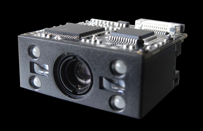
13 Chapter 1 Getting Started Introduction The NLS-EM3070 OEM scan engines (hereinafter referred to as the EM3070 or the engine ), armed with the Newland patented, a computerized image recognition system, bring about a new era of 2D barcode scan engines. The EM3070s 2D barcode decoder chip ingeniously blends technology and advanced chip design & manufacturing, which significantly simplifies application design and delivers superior performance and solid reliability with low power consumption. The EM3070s support all mainstream 1D and standard 2D barcode symbologies (e.g., PDF417, QR Code M1/M2/Micro and Data Matrix) as well as GS1-DataBarTM(RSS) (Limited/Stacked/Expanded versions). It can read barcodes on virtually any medium - paper, plastic card, mobile phones and LCD displays. This compact, lightweight engine fits easily into even the most space-constrained equipment such as data collectors, meter readers, ticket validators and PDAs. About This Guide This guide provides programming instructions for the EM3070. Users can configure the EM3070 by scanning the programming barcodes included in this manual. 1
14 The EM3070 has been properly configured for most applications and can be put into use without further configuration. Users may check the Factory Defaults Table in Appendix for reference. Throughout the manual, asterisks (**) indicate factory default values. Connecting EVK to PC The EVK tool is provided to assist users in application development for the EM3070. You can connect the EVK to PC via a USB connection or an RS-232 connection. In case of USB connection, a driver is required if the EVK wants to communicate with the EM3070 and receive decoded data through virtual serial port. Barcode Scanning Powered by area-imaging technology and Newland patented technology, the EM3070 features fast scanning and accurate decoding. Barcodes rotated at any angle can still be read with ease. When scanning a barcode, simply center the aiming beam or pattern projected by the EM3070 over the barcode. 2
15 Barcode Programming Scanning the Enter Setup barcode can enable the engine to enter the setup mode. Then you can scan a number of programming barcodes to configure your engine. To exit the setup mode, scan the Exit Setup barcode. If the engine has exited the setup mode, only some special programming barcodes, such as the Enter Setup barcode and Restore All Factory Defaults barcode, can be read. Enter Setup ** Exit Setup Programming barcode data can be transmitted to the Host. Scan the appropriate barcode below to enable or disable the transmission of programming barcode data (i.e. the characters under programming barcode) to the Host. Restarting the engine will automatically disable the transmisison of programming barcode data to the Host. Transmit Programming Barcode Data ** Do Not Transmit Programming Barcode Data 3
16 Factory Defaults Scanning the following barcode can restore the engine to the factory defaults. See Appendix 1: Factory Defaults Table for more information. Note: Use this feature with discretion. Restore All Factory Defaults Custom Defaults Custom defaults make it possible to save the frequently-used settings on the engine. Scanning the Save as Custom Defaults barcode can save the current settings as custom defaults. Once custom default settings are stored, they can be recovered at any time by scanning the Restore All Custom Defaults barcode. Custom defaults are stored in the non-volatile memory. Restoring the engine to the factory defaults will not remove the custom defaults from the engine. Save as Custom Defaults Restore All Custom Defaults Inquire Product Information You can scan the barcode below to inquire the engine information (such as firmware version, model number, serial number, manufacture date). The result will be sent to the Host. Inquire Product Information 4
17 Chapter 2 Communication Interfaces The EM3070 provides a TTL-232 interface and a USB interface to communicate with the host device. The host device can receive scanned data and send commands to control the engine or to access/alter the configuration information of the engine via the TTL-232 or USB interface. Power-Saving Mode By default, the engine adopts the Normal Mode which supports both TTL-232 and USB. The Power-Saving Mode is designed to conserve power. However, you can only use TTL-232 communication in the Power-Saving Mode. ** Normal Mode (TTL-232 & USB supported) Power-Saving Mode (TTL-232 supported) 5 * Exit Setup
18 TTL-232 Interface Serial communication interface is usually used when connecting the engine to a host device (like PC, POS). However, to ensure smooth communication and accuracy of data, you need to set communication parameters (including baud rate, parity check, data bit and stop bit) to match the host device. The serial communication interface provided by the engine is based on TTL-level signals. TTL-232 can be used for most application architectures. For those requiring RS-232, an external conversion circuit is needed. The conversion circuit is available only to some models. Serial Communication Default serial communication parameters are listed below. Make sure all parameters match the host requirements. Parameter Factory Default Serial Communication Standard TTL-232 Baud Rate 9600 Parity Check None Data Bits 8 Stop Bits 1 Hardware Flow Control None * Exit Setup 6
19 Baud Rate Baud rate is the number of bits of data transmitted per second. Set the baud rate to match the Host requirements. ** * Exit Setup
20 Parity Check When the number of data bits is set to 7, you can only select either Even Parity or Odd Parity. The None option will be regarded as Even Parity in this case. ** None Even Parity Odd Parity Data Bit When the number of data bits is set to 7, you can only select either Even Parity or Odd Parity. 7 Data Bits ** 8 Data Bits * Exit Setup 8
21 Data Bit & Parity Check 7 Data Bits/Even Parity 7 Data Bits/Odd Parity ** 8 Data Bits/ No Parity 8 Data Bits/Even Parity 8 Data Bits/Odd Parity Stop Bit ** 1 Stop Bit 2 Stop Bits 9 * Exit Setup
22 USB Interface USB Enumeration If the engine is connected to the Host via a USB connection, the engine will be enumerated using S/N or after power-up. Enumeration using S/N enables the Host to distinguish even between engines of same model. Enumeration using disables the Host from distinguishing between engines of same model. Driver installation is required for each USB device distinguished from others by the Host in the process of enumeration. Enumeration Using S/N ** Enumeration Using USB HID-KBW When you connect the engine to the Host via a USB connection, you can enable the USB HID-KBW feature by scanning the barcode below. Then engine s transmission will be simulated as USB keyboard input. The Host receives keystrokes on the virtual keyboard. It works on a Plug and Play basis and no driver is required. ** USB HID-KBW * Exit Setup 10
23 Polling Rate This parameter specifies the polling rate for a USB keyboard. If the Host drops characters, change the polling rate to a bigger value. ** 1ms 2ms 3ms 4ms 5ms 6ms 7ms 8ms 9ms 10ms 11 * Exit Setup
24 USB Country Keyboard Types Keyboard layouts vary from country to country. The default setting is 1-U.S. keyboard. ** U.S. Japan Denmark Finland France Turkey_F Italy Norway * Exit Setup 12
25 Spain Turkey_Q UK Austria, Germany Belgium Russia Sweden Portugal Note: To program the engine to get proper output for Russian encoded with Windows 1251 or UTF-8 (PDF417/QR Code/Data Matrix), see Appendix * Exit Setup
26 Beep on Unknown Character Due to the differences in keyboard layouts, some characters contained in barcode data may be unavailable on the selected keyboard. As a result, the engine fails to transmit the unknown characters. Scan the appropriate barcode below to enable or disable the emission of beep when an unknown character is detected. Beep on Unknown Character ** Do Not Beep on Unknown Character Inter-Keystroke Delay This parameter specifies the delay between emulated keystrokes. It is programmable in 5ms increments from 0ms to 75ms. Single-digit values must have a leading zero. To learn how to program custom delay, see Appendix 5. The default setting is 10ms. No Delay Short Delay (20ms) Long Delay (40ms) Custom Delay * Exit Setup 14
27 Convert Case Scan the appropriate barcode below to convert barcode data to your desired case. ** No Case Conversion Invert Upper and Lower Case Characters Convert All to Upper Case Convert All to Lower Case Example: When the Convert All to Lower Case feature is enabled, barcode data AbC is transmitted as abc. 15 * Exit Setup

28 Emulate ALT+Keypad This feature allows any ASCII character (0x00-0xFF) to be sent over the numeric keypad no matter which keyboard type is selected. Since sending a character involves multiple keystroke emulations, this method appears less efficient. The following options are available: Disable: No ASCII character is sent in the ALT+Keypad way. Mode 1: ASCII characters not supported by the selected keyboard type but falling into 0x20~0xFF are sent in the ALT+Keypad way. Mode 2: ASCII characters falling into 0x20~0xFF are sent in the ALT+Keypad way. Mode 3: All ASCII characters (0x00~0xFF) are sent in the ALT+Keypad way. Note: In the event of a conflict between Function Key Mapping and Mode 3, Function Key Mapping shall govern. ** Disable Mode 1 Mode 2 Mode 3 Example: Supposing US keyboard is selected, barcode data AÐF (65/208/70) is sent as below: (1) Mode 1 is enabled: A -- Keystroke A Ð -- ALT Make ALT Break F -- Keystroke F (2) Mode 3 is enabled: A ALT Make ALT Break Ð -- ALT Make ALT Break F -- ALT Make ALT Break * Exit Setup 16

29 Function Key Mapping When Function Key Mapping is enabled, function characters (0x00-0x1F) are sent as ASCII sequences over the keypad. For more information, see Appendix 8: ASCII Function Key Mapping Table. Enable Function Key Mapping ** Disable Function Key Mapping Example: Barcode data 0x16 Enable Function Key Mapping Ctrl+V Disable Function Key Mapping F1 17 * Exit Setup
30 Emulate Numeric Keypad When this feature is disabled, sending barcode data is emulated as keystroke(s) on main keyboard. To enable this feature, scan the Emulate Numeric Keypad barcode. Sending a number (0-9) is emulated as keystroke(s) on numeric keypad, whereas sending other characters like +, _, *, / and. is still emulated as keystrokes on main keyboard. ** Do Not Emulate Numeric Keypad Emulate Numeric Keypad Code Page In order to support more international characters, the Code Page programming feature is provided. This feature is only effective when ASCII characters are sent in the ALT+Keypad way. Programming a code page requires scanning numeric barcode (For more information, see Appendix 9: Code Pages List). The default code page is Windows 1252 (Latin I). To learn how to program it, see Appendix 5. Set the Code Page * Exit Setup 18
31 USB COM Port Emulation If you connect the engine to the Host via a USB connection, the USB COM Port Emulation feature allows the Host to receive data in the way as a serial port does. A driver is required for this feature. USB COM Port Emulation 19 * Exit Setup
32 USB HID-POS Introduction The USB HID-POS interface is recommended for new application programs. It can send up to 56 characters in a single USB report and appears more efficient than keyboard emulation. Features: HID based, no custom driver required. Way more efficient in communication than keyboard emulation and traditional RS-232 interface. Note: USB HID-POS does not require a custom driver. However, a HID interface on Windows 98 does. All HID interfaces employ standard driver provided by the operating system. Use defaults when installing the driver. USB HID-POS Access the Engine with Your Program Use CreateFile to access the engine as a HID device and then use ReadFile to deliver the scanned data to the application program. Use WriteFile to send data to the engine. For detailed information about USB and HID interfaces, go to * Exit Setup 20
33 Acquire Scanned Data After scanning and decoding a barcode, the engine sends the following input report: Bit Byte Report ID = 0x02 1 Length of the barcode 2-57 Decoded data (1-56) AIM ID Reserved Decoded Data Continued Send Data to the Engine This output report is used to send data to the device. All programming commands can be used. Bit Byte Report ID = 0x04 1 Length of the output data 2-63 Output data (1-62) VID/PID USB uses VID (Vendor ID) and PID (Product ID) to identify and locate a device. The VID is assigned by USB Implementers Forum. Newland s vendor ID is 1EAB (Hex). A PID is assigned to each interface. Product Interface PID (Hex) PID (Dec) USB HID-KBW EM3070 USB COM Port Emulation USB HID-POS * Exit Setup
34 Chapter 3 Scan Mode Batch Mode If the Batch Mode is enabled, driving the TRIG pin on the host interface connector low activates a round of multiple decode sessions. This round of multiple scans continues until the active trigger signal is no longer present. Rereading the same barcode is not allowed if it was decoded previously in the same round. For good read, the engine transmits decoded data via communication port. To activate another round of multiple scans, the Host needs to first negate the trigger, waits 20ms or longer and then drive the TRIG pin low. Batch Mode * Exit Setup 22
35 Trigger Mode If the Trigger Mode is enabled, driving the TRIG pin on the host interface connector low activates a decode session. The session continues until the barcode is decoded or decode session timeout expires or the active trigger signal is no longer present. For good read, the engine transmits decoded data via communication port. To activate another session, the Host needs to first negate the trigger, waits 20ms or longer and then drive the TRIG pin low. ** Trigger Mode Decode Session Timeout This parameter sets the maximum time decode session continues during a scan attempt. It is programmable in 1ms increments from 1ms to 3,600,000ms. When it is set to 0, the timeout is infinite. The default setting is 3,000ms. To learn how to program this parameter, see Appendix 5. Decode Session Timeout 23 * Exit Setup
36 Level Trigger/Pulse Trigger Level trigger: Decode session is activated and continued by constant active trigger signal. The decode session ends once the barcode is decoded or decode session timeout expires. Pulse trigger: Decode session is activated by electric pulse of trigger signal. The decode session continues until the barcode is decoded or decode session timeout expires. ** Level Trigger Pulse Trigger Auto Sleep Auto Sleep allows the engine in the Trigger Mode to automatically enter the sleep or low power mode if no operation or communication is performed for a time period (user programmable). When the engine is in the sleep mode, receiving trigger signal or communication from the Host can awake the engine. The engine returns to full operation within 100ms. ** Enable Auto Sleep Disable Auto Sleep The parameter below specifies how long the engine remains idle (no operation or communication occurs) before it is put into sleep mode. It is programmable in 1ms increments from 0ms to 65,535ms. The default setting is 500ms. To learn how to program this parameter, see Appendix 5. Time Period from Idle to Sleep * Exit Setup 24
, scan the appropriate barcode below.")
37 Timeout between Decodes (Same Barcode) Timeout between Decodes (Same Barcode) can avoid undesired rereading of same barcode in a given period of time. To enable/disable the Timeout between Decodes (Same Barcode), scan the appropriate barcode below. Enable Timeout between Decodes: Do not allow the engine to re-read same barcode before the timeout between decodes (same barcode) expires. Disable Timeout between Decodes: Allow the engine to re-read same barcode. ** Disable Timeout between Decodes Enable Timeout between Decodes The following parameter sets the timeout between decodes for same barcode. It is programmable in 1ms increments from 0ms to 65,535ms. The default setting is 1,500ms. To learn how to program this parameter, see Appendix 5. Timeout between Decodes (Same Barcode) 25 * Exit Setup
38 Sense Mode If the Sense Mode is enabled, the engine activates a decode session every time it detects a change in ambient illumination. The decode session continues until the barcode is decoded or the decode session timeout expires. Driving the TRIG pin on the host interface connector low can also activate a decode session. The decode session continues until the active trigger signal is no longer present or the barcode is decoded or the decode session timeout expires. The trigger signal needs to be negated before the engine is able to monitor ambient illumination again. Sense Mode Decode Session Timeout This parameter sets the maximum time decode session continues during a scan attempt. If the timeout expires or the barcode is decoded, the engine goes back to monitoring ambient illumination. It is programmable in 1ms increments from 1ms to 3,600,000ms. When it is set to 0, the timeout is infinite. The default setting is 3,000ms. To learn how to program this parameter, see Appendix 5. Decode Session Timeout * Exit Setup 26


39 Image Stabilization Timeout This parameter defines the amount of time that the engine waits for the image to stabilize to a point that it can be decoded with more accuracy. It is programmable in 1ms increments from 0ms to 1,600ms. The default setting is 500ms.To learn how to program this parameter, see Appendix 5. Image Stabilization Timeout Timeout between Decodes This parameter sets the timeout between decode sessions. When a decode session ends, next session will not happen until the timeout between decodes expires. It is programmable in 1ms increments from 0ms to 65,535ms. The default setting is 1,000ms. To learn how to program this parameter, see Appendix 5. Timeout between Decodes Continue after Good Read Continue after Good Read: The engine starts next decode session after good read. Pause after Good Read: The engine starts another round of illumination monitoring and image stabilization after good read. ** Pause after Good Read Continue after Good Read 27 * Exit Setup
, scan the appropriate barcode below.")
40 Timeout between Decodes (Same Barcode) Timeout between Decodes (Same Barcode) can avoid undesired rereading of same barcode in a given period of time. To enable/disable the Timeout between Decodes (Same Barcode), scan the appropriate barcode below. Enable Timeout between Decodes: Do not allow the engine to re-read same barcode before the timeout between decodes (same barcode) expires. Disable Timeout between Decodes: Allow the engine to re-read same barcode. ** Disable Timeout between Decodes Enable Timeout between Decodes The following parameter sets the timeout between decodes for same barcode. It is programmable in 1ms increments from 0ms to 65,535ms. The default setting is 1,500ms. To learn how to program this parameter, see Appendix 5. Timeout between Decodes (Same Barcode) * Exit Setup 28
41 Sensitivity Sensitivity specifies the degree of acuteness of the engine s response to changes in ambient illumination. The higher the sensitivity, the lower requirement in illumination change to trigger the engine. You can select an appropriate degree of sensitivity that fits the ambient environment. Medium Sensitivity Low Sensitivity High Sensitivity Enhanced Sensitivity If the above four options fail to meet your needs, you may program the threshold value of illumination change. Illumination changes that reach or surpass the predefined threshold value will cause the engine to start a decode session. The lower the threshold value, the greater the sensitivity of the engine. The default threshold value is 2. To learn how to program this parameter, see Appendix 5. Threshold Value of Illumination Change (1-20) 29 * Exit Setup
42 Continuous Mode This mode enables the engine to scan/capture, decode and transmit over and over again. When the engine is operating in Continuous Mode, barcode reading can be suspended/resumed through control over the trigger signal. When barcode reading is in progress, negating the trigger signal after having maintained it for 30ms or longer will suspend barcode reading; when barcode reading is suspended, performing the same control over the trigger signal will resume barcode reading. Continuous Mode Decode Session Timeout This parameter sets the maximum time decode session continues during a scan attempt. It is programmable in 1ms increments from 1ms to 3,600,000ms. When it is set to 0, the timeout is infinite. The default setting is 3,000ms. To learn how to program this parameter, see Appendix 5. Decode Session Timeout Timeout between Decodes This parameter sets the timeout between decode sessions. When a decode session ends, next session will not happen until the timeout between decodes expires. It is programmable in 1ms increments from 0ms to 65,535ms. The default setting is 1,000ms. To learn how to program this parameter, see Appendix 5. Timeout between Decodes * Exit Setup 30
43 Timeout between Decodes (Same Barcode) Timeout between Decodes (Same Barcode) can avoid undesired rereading of same barcode in a given period of time. To enable/disable the Timeout between Decodes (Same Barcode), scan the appropriate barcode below. Enable Timeout between Decodes: Do not allow the engine to re-read same barcode before the timeout between decodes (same barcode) expires. Disable Timeout between Decodes: Allow the engine to re-read same barcode. ** Disable Timeout between Decodes Enable Timeout between Decodes The following parameter sets the timeout between decodes for same barcode. It is programmable in 1ms increments from 0ms to 65,535ms. The default setting is 1,500ms. To learn how to program this parameter, see Appendix 5. Timeout between Decodes (Same Barcode) 31 * Exit Setup
44 Chapter 4 Illumination & Aiming Illumination A couple of illumination options are provided to improve the lighting conditions during every image capture: Normal: Illumination LEDs are turned on during image capture. Always ON: Illumination LEDs keep ON after the engine is powered on. OFF: Illumination LEDs are OFF all the time. ** Normal OFF Always ON * Exit Setup 32
45 Aiming When scanning/capturing image, the engine projects an aiming pattern which allows positioning the target barcode within its field of view and thus makes decoding easier. Normal: The engine projects an aiming pattern only during barcode scanning/capture. Always ON: Aiming pattern is constantly ON after the engine is powered on. OFF: Aiming pattern is OFF all the time. ** Normal OFF Always ON 33 * Exit Setup
46 Chapter 5 Beep & LED Notifications Startup Beep If startup beep is enabled, the engine will beep after being turned on. ** Enable Startup Beep Disable Startup Beep * Exit Setup 34
47 Good Read Beep for Non-programming Barcode The engine can provide a PWM output to an external driver circuit to drive a beeper after decoding a non-programming barcode. Scan the appropriate barcode below to enable or disable the emission of good read beep. Beep type (frequency) and volume are also user programmable. ** Good Read Beep On for Non-programming Barcode Good Read Beep Off for Non-programming Barcode Beep Type Type 1 ** Type 3 Type 2 35 * Exit Setup
48 Beep Volume ** Loud Low Medium Beep on Unknown Character Due to the differences in keyboard layouts, some characters contained in barcode data may be unavailable on the selected keyboard (USB HID-KBW). As a result, the engine fails to transmit the unknown characters. Scan the appropriate barcode below to enable or disable the emission of beep when an unknown character is detected. Beep on Unknown Character ** Do Not Beep on Unknown Character * Exit Setup 36
49 Good Read Beep for Programming Barcode ** Good Read Beep On for Programming Barcode Good Read Beep Off for Programming Barcode Good Read LED ** Good Read LED ON Good Read LED OFF 37 * Exit Setup
50 Transmit NGR Message Scan a barcode below to select whether or not to transmit a user-defined NGR (Not Good Read) message when a barcode is not decoded. Transmit NGR Message ** Do Not Transmit NGR Message Edit NGR Message To edit an NGR message, scan the Edit NGR Message barcode and the numeric barcodes corresponding to the ASCII values (decimal) of desired characters and then scan the Save barcode. An NGR message can contain 0-7 characters (ASCII value of character: 0-255). Edit NGR Message * Exit Setup 38
51 Chapter 6 Prefix & Suffix In many applications, barcode data needs to be edited and distinguished from one another. Usually AIM ID and Code ID can be used as identifiers, but in some special cases customized prefix and terminating character suffix like Carriage Return or Line Feed can also be the alternatives. Data formatting may include: Append AIM ID/Code ID/custom prefix before the decoded data Append custom suffix after the decoded data Append terminating character to the end of the data The following formats can be used when editing barcode data: [Code ID] + [Custom Prefix] + [AIM ID] + [DATA] + [Custom Suffix] + [Terminating Character] [Custom Prefix] + [Code ID] + [AIM ID] + [DATA] + [Custom Suffix] + [Terminating Character] 39 * Exit Setup
52 Global Settings Enable/Disable All Prefix/Suffix Disable All Prefix/Suffix: Transmit barcode data with no prefix/suffix. Enable All Prefix/Suffix: Allow user to append Code ID prefix, AIM ID prefix, custom prefix/suffix and terminating character to the barcode data before the transmission. Enable All Prefix/Suffix Disable All Prefix/Suffix Prefix Sequences Code ID+Custom Prefix+AIM ID ** Custom Prefix+Code ID+AIM ID * Exit Setup 40
53 Custom Prefix Enable/Disable Custom Prefix If custom prefix is enabled, you are allowed to append to the data a user-defined prefix that cannot exceed 11 characters. Enable Custom Prefix ** Disable Custom Prefix Set Custom Prefix To set a custom prefix, scan the Set Custom Prefix barcode and the numeric barcodes representing the hexadecimal values of a desired prefix and then scan the Save barcode. Refer to Appendix 4: ASCII Table for hexadecimal values of characters. To learn how to program this parameter, see Appendix 5. Note: A custom prefix cannot exceed 11 characters. Set Custom Prefix 41 * Exit Setup
54 AIM ID Prefix AIM (Automatic Identification Manufacturers) IDs and ISO/IEC standards define symbology identifiers and data carrier identifiers. (For the details, see the Appendix 2: AIM ID Table section). If AIM ID prefix is enabled, the engine will add the symbology identifier before the scanned data after decoding. Enable AIM ID Prefix ** Disable AIM ID Prefix Code ID Prefix Code ID can also be used to identify barcode type. Unlike AIM ID, Code ID is user programmable. Code ID can only consist of one or two English letters. Enable Code ID Prefix ** Disable Code ID Prefix Restore All Default Code IDs For the information of default Code IDs, see the Appendix 3: Code ID Table section. Restore All Default Code IDs * Exit Setup 42
55 Modify Code ID Code ID of each symbology can be programmed separately. To learn how to program this parameter, see Appendix 5. Modify PDF417 Code ID Modify Data Matrix Code ID Modify QR Code Code ID Modify Code 128 Code ID Modify GS1-128 Code ID Modify AIM-128 Code ID Modify EAN-8 Code ID Modify EAN-13 Code ID 43 * Exit Setup
56 Modify UPC-E Code ID Modify UPC-A Code ID Modify ISBN Code ID Modify ISSN Code ID Modify Code 39 Code ID Modify Code 93 Code ID Modify Interleaved 2 of 5 Code ID Modify ITF-14 Code ID Modify ITF-6 Code ID Modify Codabar Code ID * Exit Setup 44
57 Modify Industrial 25 Code ID Modify Standard 25 Code ID Modify Matrix 25 Code ID Modify COOP 25 Code ID Modify Code 11 Code ID Modify Plessey Code ID Modify MSI/Plessey Code ID Modify GS1 Databar Code ID 45 * Exit Setup
58 Custom Suffix Enable/Disable Custom Suffix If custom suffix is enabled, you are allowed to append to the data a user-defined suffix that cannot exceed 11 characters. Enable Custom Suffix ** Disable Custom Suffix Set Custom Suffix To set a custom suffix, scan the Set Custom Suffix barcode and the numeric barcodes representing the hexadecimal values of a desired suffix and then scan the Save barcode. Refer to Appendix 4: ASCII Table for hexadecimal values of characters. To learn how to program this parameter, see Appendix 5. Note: A custom suffix cannot exceed 11 characters. Set Custom Suffix * Exit Setup 46
59 Terminating Character Suffix A terminating character can be used to mark the end of data, which means nothing can be added after it. A terminating character suffix cannot exceed 7 characters. Enable/Disable Terminating Character Suffix To enable/disable terminating character suffix, scan the appropriate barcode below. ** Enable Terminating Character Suffix Disable Terminating Character Suffix 47 * Exit Setup
60 Set Terminating Character Suffix The engine provides a shortcut for setting the terminating character suffix to CR (0x0D) or CRLF (0x0D,0x0A) and enabling it by scanning the appropriate barcode below. ** Terminating Character CR (0x0D) Terminating Character CRLF (0x0D,0x0A) To set a terminating character suffix, scan the Set Terminating Character Suffix barcode and the numeric barcodes representing the hexadecimal value of a desired terminating character and then scan the Save barcode. Refer to Appendix 4: ASCII Table for hexadecimal values of terminating characters. To learn how to program this parameter, see Appendix 5. Note: A terminating character suffix cannot exceed 7 characters. Set Terminating Character Suffix * Exit Setup 48
61 Chapter 7 Symbologies Global Settings Enable/Disable All Symbologies If the Disable All Symbologies feature is enabled, the engine will not be able to read any non-programming barcodes except the programming barcodes. Enable All Symbologies Disable All Symbologies Enable/Disable 1D Symbologies If the Disable 1D Symbologies feature is enabled, the engine will not be able to read any 1D barcodes. Enable 1D Symbologies Disable 1D Symbologies Enable/Disable 2D Symbologies If the Disable 2D Symbologies feature is enabled, the engine will not be able to read any 2D barcodes. Enable 2D Symbologies Disable 2D Symbologies 49 * Exit Setup


62 Video Reverse The Video Reverse feature only applies to 2D barcodes. Regular barcode: Dark image on a bright background. Inverse barcode: Bright image on a dark background. The examples of regular barcode and inverse barcode are shown below. Regular Barcode Inverse Barcode Video Reverse is used to allow the engine to read barcodes that are inverted. Video Reverse ON: Read both regular barcodes and inverse barcodes. Video Reverse OFF: Read regular barcodes only. The engine shows a slight decrease in scanning speed when Video Reverse is ON. Video Reverse ON ** Video Reverse OFF * Exit Setup 50
63 1D Symbologies Code 128 Restore Factory Defaults Restore the Factory Defaults of Code 128 Enable/Disable Code 128 ** Enable Code 128 Disable Code 128 Set Length Range for Code 128 Set the Minimum Length Set the Maximum Length 51 * Exit Setup
64 GS1-128 (UCC/EAN-128) Restore Factory Defaults Restore the Factory Defaults of GS1-128 Enable/Disable GS1-128 ** Enable GS1-128 Disable GS1-128 Set Length Range for GS1-128 Set the Minimum Length Set the Maximum Length * Exit Setup 52
65 AIM-128 Restore Factory Defaults Restore the Factory Defaults of AIM-128 Enable/Disable AIM-128 ** Enable AIM-128 Disable AIM-128 Set Length Range for AIM-128 Set the Minimum Length Set the Maximum Length 53 * Exit Setup
66 EAN-8 Restore Factory Defaults Restore the Factory Defaults of EAN-8 Enable/Disable EAN-8 ** Enable EAN-8 Disable EAN-8 * Exit Setup 54


67 Transmit Check Digit EAN-8 is 8 digits in length with the last one as its check digit used to verify the integrity of the data. ** Transmit EAN-8 Check Digit Do Not Transmit EAN-8 Check Digit Add-On Code An EAN-8 barcode can be augmented with a two-digit or five-digit add-on code to form a new one. In the examples below, the part surrounded by blue dotted line is an EAN-8 barcode while the part circled by red dotted line is add-on code. Enable 2-Digit Add-On Code ** Disable 2-Digit Add-On Code Enable 5-Digit Add-On Code ** Disable 5-Digit Add-On Code Enable 2-Digit Add-On Code/ Enable 5-Digit Add-On Code: The engine decodes a mix of EAN-8 barcodes with and without 2-digit/5-digit add-on codes. Disable 2-Digit Add-On Code/ Disable 5-Digit Add-On Code: The engine decodes EAN-8 and ignores the add-on code when presented with an EAN-8 plus add-on barcode. It can also decode EAN-8 barcodes without add-on codes. 55 * Exit Setup
68 Add-On Code Required When EAN-8 Add-On Code Required is selected, the engine will only read EAN-8 barcodes that contain add-on codes. EAN-8 Add-On Code Required ** EAN-8 Add-On Code Not Required EAN-8 Extension Disable EAN-8 Zero Extend: Transmit EAN-8 barcodes as is. Enable EAN-8 Zero Extend: Add five leading zeros to decoded EAN-8 barcodes to extend to13 digits. Enable EAN-8 Zero Extend ** Disable EAN-8 Zero Extend * Exit Setup 56
69 EAN-13 Restore Factory Defaults Restore the Factory Defaults of EAN-13 Enable/Disable EAN-13 ** Enable EAN-13 Disable EAN-13 Transmit Check Digit ** Transmit EAN-13 Check Digit Do Not Transmit EAN-13 Check Digit 57 * Exit Setup
70 Add-On Code An EAN-13 barcode can be augmented with a two-digit or five-digit add-on code to form a new one. Enable 2-Digit Add-On Code ** Disable 2-Digit Add-On Code Enable 5-Digit Add-On Code ** Disable 5-Digit Add-On Code Enable 2-Digit Add-On Code/ Enable 5-Digit Add-On Code: The engine decodes a mix of EAN-13 barcodes with and without 2-digit/5-digit add-on codes. Disable 2-Digit Add-On Code/ Disable 5-Digit Add-On Code: The engine decodes EAN-13 and ignores the add-on code when presented with an EAN-13 plus add-on barcode. It can also decode EAN-13 barcodes without add-on codes. Add-On Code Required When EAN-13 Add-On Code Required is selected, the engine will only read EAN-13 barcodes that contain add-on codes. EAN-13 Add-On Code Required ** EAN-13 Add-On Code Not Required * Exit Setup 58
71 ISSN Restore Factory Defaults Restore the Factory Defaults of ISSN Enable/Disable ISSN Enable ISSN ** Disable ISSN 59 * Exit Setup
72 Add-On Code An ISSN barcode can be augmented with a two-digit or five-digit add-on code to form a new one. Enable 2-Digit Add-On Code ** Disable 2-Digit Add-On Code Enable 5-Digit Add-On Code ** Disable 5-Digit Add-On Code Enable 2-Digit Add-On Code/ Enable 5-Digit Add-On Code: The engine decodes a mix of ISSN barcodes with and without 2-digit/5-digit add-on codes. Disable 2-Digit Add-On Code/ Disable 5-Digit Add-On Code: The engine decodes ISSN and ignores the add-on code when presented with an ISSN plus add-on barcode. It can also decode ISSN barcodes without add-on codes. Add-On Code Required When ISSN Add-On Code Required is selected, the engine will only read ISSN barcodes that contain add-on codes. ISSN Add-On Code Required ** ISSN Add-On Code Not Required * Exit Setup 60
73 ISBN Restore Factory Default Restore the Factory Defaults of ISBN Enable/Disable ISBN ** Enable ISBN Disable ISBN Set ISBN Format **ISBN-13 ISBN * Exit Setup
74 Add-On Code An ISBN barcode can be augmented with a two-digit or five-digit add-on code to form a new one. Enable 2-Digit Add-On Code ** Disable 2-Digit Add-On Code Enable 5-Digit Add-On Code ** Disable 5-Digit Add-On Code Enable 2-Digit Add-On Code/ Enable 5-Digit Add-On Code: The engine decodes a mix of ISBN barcodes with and without 2-digit/5-digit add-on codes. Disable 2-Digit Add-On Code/ Disable 5-Digit Add-On Code: The engine decodes ISBN and ignores the add-on code when presented with an ISBN plus add-on barcode. It can also decode ISBN barcodes without add-on codes. Add-On Code Required When ISBN Add-On Code Required is selected, the engine will only read ISBN barcodes that contain add-on codes. ISBN Add-On Code Required ** ISBN Add-On Code Not Required * Exit Setup 62
75 UPC-E Restore Factory Defaults Restore the Factory Defaults of UPC-E Enable/Disable UPC-E ** Enable UPC-E Disable UPC-E Transmit Check Digit ** Transmit UPC-E Check Digit Do Not Transmit UPC-E Check Digit 63 * Exit Setup
76 Add-On Code A UPC-E barcode can be augmented with a two-digit or five-digit add-on code to form a new one. Enable 2-Digit Add-On Code ** Disable 2-Digit Add-On Code Enable 5-Digit Add-On Code ** Disable 5-Digit Add-On Code Enable 2-Digit Add-On Code/ Enable 5-Digit Add-On Code: The engine decodes a mix of UPC-E barcodes with and without 2-digit/5-digit add-on codes. Disable 2-Digit Add-On Code/ Disable 5-Digit Add-On Code: The engine decodes UPC-E and ignores the add-on code when presented with a UPC-E plus add-on barcode. It can also decode UPC-E barcodes without add-on codes. Add-On Code Required When UPC-E Add-On Code Required is selected, the engine will only read UPC-E barcodes that contain add-on codes. UPC-E Add-On Code Required ** UPC-E Add-On Code Not Required * Exit Setup 64
77 Transmit System Character 0 The first character of UPC-E barcode is the system character 0. ** Transmit System Character 0 Do Not Transmit System Character 0 UPC-E Extension Disable UPC-E Extend: Transmit UPC-E barcodes as is. Enable UPC-E Extend: Extend UPC-E barcodes to make them compatible in length to UPC-A. Enable UPC-E Extend ** Disable UPC-E Extend 65 * Exit Setup
78 UPC-A Restore Factory Defaults Restore the Factory Defaults of UPC-A Enable/Disable UPC-A ** Enable UPC-A Disable UPC-A Transmit Check Digit ** Transmit UPC-A Check Digit Do Not Transmit UPC-A Check Digit * Exit Setup 66
79 Add-On Code A UPC-A barcode can be augmented with a two-digit or five-digit add-on code to form a new one. Enable 2-Digit Add-On Code ** Disable 2-Digit Add-On Code Enable 5-Digit Add-On Code ** Disable 5-Digit Add-On Code Enable 2-Digit Add-On Code/ Enable 5-Digit Add-On Code: The engine decodes a mix of UPC-A barcodes with and without 2-digit/5-digit add-on codes. Disable 2-Digit Add-On Code/ Disable 5-Digit Add-On Code: The engine decodes UPC-A and ignores the add-on code when presented with a UPC-A plus add-on barcode. It can also decode UPC-A barcodes without add-on codes. Add-On Code Required When UPC-A Add-On Code Required is selected, the engine will only read UPC-A barcodes that contain add-on codes. UPC-A Add-On Code Required ** UPC-A Add-On Code Not Required 67 * Exit Setup
80 Transmit Preamble Character Preamble characters (Country Code and System Character) can be transmitted as part of a UPC-A barcode. Select one of the following options for transmitting UPC-A preamble to the host device: transmit system character only or transmit system character and country code ( 0 for USA). System Character & Country Code ** System Character * Exit Setup 68
81 Interleaved 2 of 5 Restore Factory Defaults Restore the Factory Defaults of Interleaved 2 of 5 Enable/Disable Interleaved 2 of 5 ** Enable Interleaved 2 of 5 Disable Interleaved 2 of 5 Set Length Range for Interleaved 2 of 5 Set the Minimum Length Set the Maximum Length 69 * Exit Setup
82 Check Digit Verification A check digit is optional for Interleaved 2 of 5 and can be added as the last digit. It is a calculated value used to verify the integrity of the data. Disable: The engine transmits Interleaved 2 of 5 barcodes as is. Do Not Transmit Check Digit After Verification: The engine checks the integrity of all Interleaved 2 of 5 barcodes to verify that the data complies with the check digit algorithm. Barcodes passing the check will be transmitted except the last digit, whereas those failing it will not be transmitted. Transmit Check Digit After Verification: The engine checks the integrity of all Interleaved 2 of 5 barcodes to verify that the data complies with the check digit algorithm. Barcodes passing the check will be transmitted, whereas those failing it will not be transmitted. ** Disable Do Not Transmit Check Digit After Verification Transmit Check Digit After Verification Note: If the Do Not Transmit Check Digit After Verification option is enabled, Interleaved 2 of 5 barcodes with a length that is less than the configured minimum length after having the check digit excluded will not be decoded. (For example, when the Do Not Transmit Check Digit After Verification option is enabled and the minimum length is set to 4, Interleaved 2 of 5 barcodes with a total length of 4 characters including the check digit cannot be read.) * Exit Setup 70
83 ITF-14 ITF-14 is a special kind of Interleaved 2 of 5 with a length of 14 characters and the last character as the check character. Restore the Factory Defaults of ITF-14 Disable ITF-14 ** Enable ITF-14 But Do Not Transmit Check Digit Enable ITF-14 and Transmit Check Digit Note: It is advisable not to enable ITF-14 and Interleaved 2 of 5 at the same time. 71 * Exit Setup
84 ITF-6 ITF-6 is a special kind of Interleaved 2 of 5 with a length of 6 characters and the last character as the check character. Restore the Factory Defaults of ITF-6 ** Disable ITF-6 Enable ITF-6 But Do Not Transmit Check Digit Enable ITF-6 and Transmit Check Digit Note: It is advisable not to enable ITF-6 and Interleaved 2 of 5 at the same time. * Exit Setup 72
85 Matrix 2 of 5 Restore Factory Defaults Restore the Factory Defaults of Matrix 2 of 5 Enable/Disable Matrix 2 of 5 Enable Matrix 2 of 5 ** Disable Matrix 2 of 5 Set Length Range for Matrix 2 of 5 Set the Minimum Length Set the Maximum Length 73 * Exit Setup
86 Check Digit Verification Disable ** Do Not Transmit Check Digit After Verification Transmit Check Digit After Verification * Exit Setup 74
87 Industrial 2 of 5 Restore Factory Defaults Restore the Factory Defaults of Industrial 2 of 5 Enable/Disable Industrial 2 of 5 ** Enable Industrial 2 of 5 Disable Industrial 2 of 5 Set Length Range for Industrial 2 of 5 Set the Minimum Length Set the Maximum Length 75 * Exit Setup
88 Check Digit Verification ** Disable Transmit Check Digit After Verification Do Not Transmit Check Digit After Verification * Exit Setup 76
89 Standard 2 of 5(IATA 2 of 5) Restore Factory Defaults Restore the Factory Defaults of Standard 25 Enable/Disable Standard 25 ** Enable Standard 25 Disable Standard 25 Set Length Range for Standard 25 Set the Minimum Length Set the Maximum Length 77 * Exit Setup
90 Check Digit Verification ** Disable Transmit Check Digit After Verification Do Not Transmit Check Digit After Verification * Exit Setup 78
91 Code 39 Restore Factory Defaults Restore the Factory Defaults of Code 39 Enable/Disable Code 39 ** Enable Code 39 Disable Code 39 Transmit Start/Stop Character Transmit Start/Stop Character ** Do not Transmit Start/Stop Character 79 * Exit Setup
92 Set Length Range for Code 39 Set the Minimum Length Set the Maximum Length Check Digit Verification ** Disable Transmit Check Digit After Verification Do Not Transmit Check Digit After Verification Enable/Disable Code 39 Full ASCII The engine can be configured to identify all ASCII characters by scanning the appropriate barcode below. ** Enable Code 39 Full ASCII Disable Code 39 Full ASCII * Exit Setup 80
93 Codabar Restore Factory Defaults Restore the Factory Defaults of Codabar Enable/Disable Codabar ** Enable Codabar Disable Codabar Set Length Range for Codabar Set the Minimum Length Set the Maximum Length 81 * Exit Setup
94 Check Digit Verification ** Disable Transmit Check Digit After Verification Do Not Transmit Check Digit After Verification Transmit Start/Stop Character Transmit Start/Stop Character ** Do not Transmit Start/Stop Character * Exit Setup 82
95 Start/Stop Character Format You can choose your desired start/stop character format by scanning the appropriate barcode below. ** ABCD/ABCD as the Start/Stop Character ABCD/TN*E as the Start/Stop Character Start/Stop Character in Uppercase Start/Stop Character in Lowercase 83 * Exit Setup
96 Code 93 Restore Factory Defaults Restore the Factory Defaults of Code 93 Enable/Disable Code 93 ** Enable Code 93 Disable Code 93 Set Length Range for Code 93 Set the Minimum Length Set the Maximum Length * Exit Setup 84
97 Check Digit Verification Disable ** Do Not Transmit Check Digit After Verification Transmit Check Digit After Verification 85 * Exit Setup
98 GS1-Databar (RSS) Restore Factory Defaults Restore the Factory Defaults of GS1-Databar Enable/Disable GS1 Databar ** Enable GS1-DataBar Disable GS1-DataBar Transmit Application Identifier 01 ** Transmit Application Identifier 01 Do Not Transmit Application Identifier 01 * Exit Setup 86
99 Code 11 Restore Factory Defaults Restore the Factory Defaults of Code 11 Enable/Disable Code 11 ** Enable Code 11 Disable Code 11 Set Length Range for Code 11 Set the Minimum Length Set the Maximum Length 87 * Exit Setup
100 Transmit Check Digit Transmit Check Digit ** Do Not Transmit Check Digit Check Digit Verification Disable ** One Check Digit, MOD11 Two Check Digits, MOD11/MOD11 Two Check Digits, MOD11/MOD9 One Check Digit, MOD11 (Len<=10) Two Check Digits, MOD11/MOD11 (Len>10) One Check Digit, MOD11 (Len<=10) Two Check Digits, MOD11/MOD9 (Len>10) * Exit Setup 88
101 Plessey Restore Factory Defaults Restore the Factory Defaults of Plessey Enable/Disable Plessey ** Enable Plessey Disable Plessey Set Length Range for Plessey Set the Minimum Length Set the Maximum Length 89 * Exit Setup
102 Check Digit Verification Disable ** Do Not Transmit Check Digit After Verification Transmit Check Digit After Verification * Exit Setup 90
103 MSI-Plessey Restore Factory Defaults Restore the Factory Defaults of MSI-Plessey Enable/Disable MSI-Plessey ** Enable MSI-Plessey Disable MSI-Plessey Set Length Range for MSI-Plessey Set the Minimum Length Set the Maximum Length 91 * Exit Setup
104 Transmit Check Digit Transmit Check Digit ** Do Not Transmit Check Digit Check Digit Verification Disable ** One Check Digit, MOD10 Two Check Digits, MOD10/MOD10 Two Check Digits, MOD10/MOD11 * Exit Setup 92
105 2D Symbologies PDF 417 Restore Factory Defaults Restore the Factory Defaults of PDF 417 Enable/Disable PDF 417 ** Enable PDF 417 Disable PDF 417 Set Length Range for PDF 417 Set the Minimum Length Set the Maximum Length 93 * Exit Setup
106 PDF 417 Twin Code PDF417 twin code is 2 PDF417 barcodes paralleled vertically or horizontally. They must both be either regular or inverse barcodes. They must have similar specifications and be placed closely together. There are 3 options for reading PDF417 twin codes: Single PDF417 Only: Read either PDF417 code. Twin PDF417 Only: Read both PDF417 codes. Both Single & Twin: Read both PDF417 codes. If successful, transmit as twin PDF417 only. Otherwise, try single PDF417 only. ** Single PDF417 Only Twin PDF417 Only Both Single & Twin Transmission order of twin code Order 1: Transmit the one containing more information first. Order 2: Transmit the one containing less information first. ** Order 1 Order 2 * Exit Setup 94
107 Character Encoding ** Default Character Encoding UTF-8 95 * Exit Setup
108 QR Code Restore Factory Defaults Restore the Factory Defaults of QR Code Enable/Disable QR Code ** Enable QR Code Disable QR Code Set Length Range for QR Code Set the Minimum Length Set the Maximum Length Micro QR ** Enable Micro QR Disable Micro QR * Exit Setup 96

109 QR Twin Code QR twin code is 2 QR barcodes paralleled vertically or horizontally. They must both be either regular or inverse barcodes. They must have similar specifications and be placed closely together. There are 3 options for reading QR twin codes: Single QR Only: Read either QR code. Twin QR Only: Read both QR codes. Both Single & Twin: Read both QR codes. If successful, transmit as twin QR only. Otherwise, try single QR only. ** Single QR Only Twin QR Only Both Single & Twin Transmission order of twin code Order 1: Transmit the one containing more information first. Order 2: Transmit the one containing less information first. Order 3: If the twin code is paralleled horizontally, transmit the one on the left first; if it is paralleled vertically, transmit the one in the upper position first. Order 1 Order 2 ** Order 3 97 * Exit Setup
110 Character Encoding ** Default Character Encoding UTF-8 * Exit Setup 98
111 Data Matrix Restore Factory Defaults Restore the Factory Defaults of Data Matrix Enable/Disable Data Matrix ** Enable Data Matrix Disable Data Matrix Set Length Range for Data Matrix Set the Minimum Length Set the Maximum Length 99 * Exit Setup
112 Rectangular Barcode ** Enable Rectangular Barcode Disable Rectangular Barcode Mirror Image ** Decode Mirror Images Do Not Decode Mirror Images * Exit Setup 100
113 Data Matrix Twin Code Data Matrix twin code is 2 Data Matrix barcodes paralleled vertically or horizontally. They must both be either regular or inverse barcodes. They must have similar specifications and be placed closely together. There are 3 options for reading Data Matrix twin codes: Single Data Matrix Only: Read either Data Matrix code. Twin Data Matrix Only: Read both Data Matrix codes. Transmission order: Data Matrix code on the left (in the upper position) followed by the one on the right (in the lower position). Both Single & Twin: Read both Data Matrix codes. If successful, transmit as twin Data Matrix only. Otherwise, try single Data Matrix only. ** Single Data Matrix Only Twin Data Matrix Only Both Single & Twin Character Encoding ** Default Character Encoding UTF * Exit Setup
114 Chapter 8 Scanning Preferences Introduction This chapter contains information as to how to adapt your engine to various applications with preference setting. For instance, to narrow the field of view of the engine to make sure it reads only those barcodes intended by the user. Decode Area Whole Area Decoding When this option is enabled, the engine attempts to decode barcode(s) within its field of view, from the center to the periphery, and transmits the barcode that has been first decoded. ** Whole Area Decoding Specific Area Decoding The engine attempts to read barcode(s) within a specified decoding area and transmits the barcode that has been first decoded. This option allows the engine to narrow its field of view to make sure it reads only those barcodes intended by the user. For instance, if multiple barcodes are placed closely together, specific area decoding in conjunction with appropriate pre-defined decoding area will insure that only the desired barcode is read. Specific Area Decoding * Exit Setup 102
115 Specify Decoding Area If Specific Area Decoding is enabled, the engine only reads barcodes that intersect the predefined decoding area. The default decoding area is an area of 40% top, 60% bottom, 40% left and 60% right of the engine s field of view, as shown in the figure below. In the following example, the white box is the decoding area. Since Barcode 1 passes through the decoding area, it will be read. Barcode 2 does not pass through the decoding area, so it will not be read. You can define the decoding area using the Top of Decoding Area, Bottom of Decoding Area, Left of Decoding Area and Right of Decoding Area barcodes as well as numeric barcode(s) that represent(s) a desired percentage (0-100). To learn how to program decoding area, see Appendix 5. 0% Barcode Barcode % 103 * Exit Setup
116 Top of Decoding Area Bottom of Decoding Area Left of Decoding Area Right of Decoding Area * Exit Setup 104
117 Chapter 9 Image Control Ambient Illumination Ambient lighting conditions may vary from one operating environment to another, such as fluorescent lit warehouses or sunlit open spaces. Fluorescent lights may flicker when using AC power source in 50-60Hz. Usually indoor illuminance is around 1,000 lux while outdoor illuminance may reach 60,000 lux or even over 100,000 lux. Two options are provided for ambient illumination settings: Normal Illuminance: applicable to most indoor/outdoor environments. High Illuminance: applicable to special enviroments with super-intense light source. Change to this settings will not take effect until the engine reboots or wakes up from sleep. ** Normal Illuminance (0~60000lux) High Illuminance (60000~120000lux) 105 * Exit Setup
118 Image Flipping The user may get reversed images when the engine is installed in non-standard ways. When it happens, image flipping can be used to right the wrong. The following figures illustrate standard image and three flipped images. Fig.9-1 Standard Image: Image the engine should get when it is installed properly and no reflector is used in its optical imaging system. Fig.9-2 Horizontal Flipped Image: It happens when horizontal reflection occurs along the optical path. To get standard images, enable the Flip Horizontally option. Fig.9-3 Vertical Flipped Image: It happens when vertical reflection occurs along the optical path. To get standard images, enable the Flip Vertically option. Fig.9-4 Horizontal and Vertical Flipped Image: It happens when the engine is installed upside down. To get standard images, enable the Flip Horizontally and Vertically option. Fig.9-1 Standard Image Fig.9-2 Horizontal Flipped Image Fig.9-3 Vertical Flipped Image Fig.9-4 Horizontal and Vertical Flipped Image * Exit Setup 106
119 Flip ** Do Not Flip Flip Vertically Flip Horizontally Flip Horizontally and Vertically Flip Vertically Flip Vertically Do Not Flip Vertically Flip Horizontally Flip Horizontally Do Not Flip Horizontally 107 * Exit Setup
120 Chapter 10 Batch Programming Introduction Batch programming enables users to integrate a batch of commands into a single batch barcode. Listed below are batch programming rules: 1. Command format: Command + = + Parameter Value. 2. Each command is terminated by a semicolon (;). Note that there is no space between a command and its terminator semicolon. 3. Use the barcode generator software to generate a 2D batch barcode. Example: Create a batch barcode for Illumination Always On ( ), Sense Mode ( ), Decode Session Timeout ( ) = 2s: 1. Input the commands: ; ; =2000; 2. Generate a batch barcode. When setting up an engine with the above configuration, scan the Enable Batch Barcode barcode and then the batch barcode generated. Enable Batch Barcode * Exit Setup 108
121 Create a Batch Command A batch command may contain a number of individual commands each of which is terminated by a semicolon (;). Command Structure: Command (+ = + Parameter Value) 4 command syntaxes are described as below: 1. Syntax 1: Command This syntax applies to most configuration situations. Example: Set the Baud Rate to 38400bps: Enable the Sense Mode: Syntax 2: Command + = + Decimal Digit(s) This syntax applies to the options/features programming which requires the entry of parameter value (decimal), such as the Maximum/Minimum Length, Decode Session Timeout, Timeout between Decodes (Same Barcode) and Sensitivity. Example: Set the Decode Session Timeout to 3000ms: =3000 Set the Sensitivity to (level) 10: =10 3. Syntax 3: Command + = + Hexadecimal Digit(s) (e.g., 0x101A, 0x2C03) This syntax applies to the features/options programming like the Custom Prefix/Suffix, Terminating Character Suffix, Code ID Suffix, which requires the entry of parameter value (hexadecimal). Example: Set the Terminating Character Suffix to CR/LF: =0x0D0A 4. Syntax 4: Command + = + Double Quotation Marks For situations where the parameter value is visible character in Syntax 3, this syntax is also appropriate. Example: Set the Custom Prefix to AUTO-ID: = AUTO-ID 109 * Exit Setup
122 Create a Batch Barcode Batch barcodes can be produced in the format of PDF417, QR Code or Data Matrix. Example: Create a batch barcode for Illumination Always On, Sense Mode, Decode Session Timeout = 2s: 1. Input the following commands: ; ; =2000; 2. Generate a QR batch barcode. * Exit Setup 110

123 Use Batch Barcode To put a batch barcode into use, scan the following barcodes. (Use the example above.) Enter Setup Enable Batch Barcode Batch Barcode Exit Setup 111 * Exit Setup
124 Chapter 11 Troubleshooting FAQ Problem: Some barcodes cannot be read. Solution: 1. Find out the barcode type and verify that the barcode type is enabled. If the barcode parameters include check digit verification, select the Disable option. 2. If you do not know the barcode type, enable all symbologies. 3. If they are inverse barcodes (bright images on a dark background), enable the Video Reverse feature. Problem: Incorrect output. Solution: 1. If this problem happens to all barcodes and additional characters appear before/after barcode data, disable all prefix/suffix. 2. If this problem only happens to some barcodes and matches one of the following situations: a) incomplete barcode data: Enable the check digit verification. b) both the first and last characters are asterisks (*): Disable the transmission of start/stop characters of Code 39. c) a transmitted as +A : Enable Code 39 Full ASCII. Problem: Barcodes can be read, but cannot be displayed. Solution: Modify the serial port properties or change the communication mode. 1. Serial communication: Verify that the parameters (such as baud rate, data bit and stop bit) settings match the host requirements. 2. USB communication: a. USB HID-KBW: No driver is required. It can provide output to a text file, but only alphanumeric characters can be displayed. b. USB COM Port Emulation: A driver is required. You can get the output via a serial port debug tool. 112
125 Problem: Illumination and aiming beams are OFF. Solution: 1. Verify that the engine is properly powered up. 2. Send? to the engine. If the engine returns a reply of!, then send programming commands to turn on illumination and aimer. Problem: Carriage Return/Line Feed settings. Solution: See the Terminating Character Suffix section in Chapter
126 Appendix Appendix 1: Factory Defaults Table Parameter Factory Default Remark Programming Barcode Barcode Programming Disabled Programming Barcode Data Do not send Communication Settings Normal Mode Power-Saving Mode: Only TTL-232 Enabled (TTL-232 & USB supported) supported Baud Rate 9600 Parity Check None TTL-232 Data Bit 8 Stop Bit 1 Hardware Flow Control No flow control Polling Rate 1ms USB Country Keyboard Type U.S. Convert Case No conversion Inter-Keystroke Delay 10ms HID-KBW Beep on Unknown Character Do not beep Emulate ALT + Keypad Disabled Function Key Mapping Disabled Emulate Numeric Keypad Disabled Code Page Windows 1252 (Latin I) Scan Mode Scan Mode Trigger mode Decode Session Timeout 3,000ms Applicable to Trigger mode, Sense mode and Continuous mode 1~3,600,000ms; 0: Infinite. Trigger Condition Electric level Trigger Mode Auto Sleep Enabled Time Period from Idle to Sleep 500ms 0~65,535ms Timeout between Decodes (Same Barcode) Disabled 1,500ms 0~65,535ms 114
127 Parameter Factory Default Remark Decode Session Timeout 3,000ms Applicable to Trigger mode, Sense mode and Continuous mode 1~3,600,000ms; 0: Infinite. Image Stabilization Timeout 500ms 0~1,600ms Sense Mode Timeout between Decodes 1000ms Applicable to Sense mode and Continuous mode. 0~65,535ms Operation after Good Read Pause after good read Timeout between Decodes (Same Barcode) Disabled 1,500ms 0~65,535ms Threshold Value of Illumination Change 2 1~20 Decode Session Timeout 3,000ms Applicable to Trigger mode, Sense mode and Continuous mode 1~3,600,000ms; 0: Infinite. Applicable to Sense mode and Continuous Mode Timeout between Decodes 1000ms Continuous mode. 0~65,535ms Timeout between Decodes (Same Barcode) Disabled 1,500ms 0~65,535ms Illumination & Aiming Illumination Normal Aiming Normal Beep & LED Notifications Startup Beep Enabled Good Read Beep for Notification Enabled Non-Programming Beep Type Type 3 Barcode Beep Volume Loud Good Read Beep for Programming Barcode Enabled Good Read LED Enabled Do not transmit NGR (Not Good Read) Message None 115
128 Parameter Factory Default Remark Prefix & Suffix Prefix Sequence Custom Prefix AIM ID Prefix Code ID Prefix Custom Suffix Custom Prefix+Code ID+AIM ID Disabled None Disabled Disabled Disabled None Terminating Character Suffix Scanning Preferences Decode Area Specify Decoding Area Image Control Ambient Illumination Image Flipping Enabled 0x0D Whole Area Decoding 40% top, 60% bottom, 40% left, 60% right Normal illuminance Do not flip Carriage Return 116
129 Parameter Factory Default Remark Symbologies Video Reverse Disabled Applicable to all symbologies. Code 128 Code 128 Enabled Maximum Length 127 Minimum Length 1 GS1-128(UCC/EAN-128) GS1-128 Enabled Maximum Length 127 Minimum Length 1 AIM-128 AIM-128 Enabled Maximum Length 127 Minimum Length 1 EAN-8 EAN-8 Enabled Check Digit Transmit 2-Digit Add-On Code Disabled 5-Digit Add-On Code Disabled Add-On Code Not required Extend to EAN-13 Disabled EAN-13 EAN-13 Enabled Check Digit Transmit 2-Digit Add-On Code Disabled 5-Digit Add-On Code Disabled Add-On Code Not required ISSN ISSN Disabled 2-Digit Add-On Code Disabled 5-Digit Add-On Code Disabled Add-On Code Not required 117
130 Parameter Factory Default Remark ISBN ISBN Enabled ISBN Format ISBN-13 2-Digit Add-On Code Disabled 5-Digit Add-On Code Disabled Add-On Code Not required UPC-E UPC-E Enabled Check Digit Transmit 2-Digit Add-On Code Disabled 5-Digit Add-On Code Disabled Add-On Code Not required Extend to UPC-A Disabled System Character 0 Transmit UPC-A UPC-A Enabled Check Digit Transmit 2-Digit Add-On Code Disabled 5-Digit Add-On Code Disabled Add-On Code Not required System Character Transmit Country Code Do not transmit Interleaved 2 of 5 Interleaved 2 of 5 Enabled Check Digit Verification Disabled Check Digit Do not transmit Maximum Length 100 Minimum Length 6 ITF-6 ITF-6 Disabled Check Digit Do not transmit 118
131 Parameter Factory Default Remark ITF-14 ITF-14 Enabled Check Digit Do not transmit Matrix 2 of 5 Matrix 2 of 5 Disabled Check Digit Verification Enabled Check Digit Do not transmit Maximum Length 127 Minimum Length 6 Industrial 2 of 5 Industrial 2 of 5 Enabled Check Digit Verification Disabled Check Digit Do not transmit Maximum Length 127 Minimum Length 6 Standard 2 of 5 Standard 2 of 5 Enabled Check Digit Verification Disabled Check Digit Do not transmit Maximum Length 127 Minimum Length 6 Code 39 Code 39 Enabled Check Digit Verification Disabled Check Digit Do not transmit Start/Stop Character Do not transmit Code 39 Full ASCII Enabled Maximum Length 127 Minimum Length 2 119
132 Parameter Factory Default Remark Codabar Codabar Enabled Check Digit Verification Disabled Check Digit Do not transmit Start/Stop Character Do not transmit Start/Stop Character Format ABCD/ABCD Maximum Length 127 Minimum Length 2 Code 93 Code 93 Enabled Check Digit Verification Enabled Check Digit Do not transmit Maximum Length 127 Minimum Length 3 GS1 Databar GS1 Databar Enabled Application Identifier 01 Transmit Code 11 Code 11 Enabled Check Digit Verification One check digit, MOD11 Check Digit Do not transmit Maximum Length 127 Minimum Length 2 Plessey Plessey Enabled Check Digit Verification Enabled Check Digit Do not transmit Maximum Length 127 Minimum Length 1 120
133 Parameter Factory Default Remark MSI-Plessey MSI-Plessey Enabled Check Digit Verification One check digit, MOD10 Check Digit Do not transmit Maximum Length 127 Minimum Length 2 PDF 417 PDF 417 Enabled Maximum Length 2710 Minimum Length 1 PDF 417 Twin Code Read single PDF417 only Transmission Order of Twin Code Order 1 Character Encoding Default Character Encoding QR Code QR Code Enabled Micro QR Enabled Maximum Length 7089 Minimum Length 1 QR Twin Code Read single QR only Transmission Order of Twin Code Order 3 Character Encoding Default Character Encoding Data Matrix Data Matrix Enabled Rectangular Barcode Enabled Mirror Image Decode Maximum Length 3116 Minimum Length 1 DM Twin Code Read single DM only Character Encoding Default Character Encoding Note: The information in the tables above is for reference only. Factory default values may differ from model to model. 121
134 Appendix 2: AIM ID Table Symbology AIM ID Remark EAN-13 ]E0 Standard EAN-13 ]E3 EAN /5-Digit Add-On Code ]E4 Standard EAN-8 EAN-8 ]E4 ]E1 EAN Digit Add-On Code ]E4 ]E2 EAN Digit Add-On Code UPC-E ]E0 Standard UPC-E ]E3 UPC-E + 2/5-Digit Add-On Code UPC-A ]E0 Standard UPC-A ]E3 UPC-A + 2/5-Digit Add-On Code Code 128 ]C0 Standard Code 128 GS1-128 (UCC/EAN-128) ]C1 FNC1 is the character right after the start character AIM-128 ]C2 FNC1 is the 2nd character after the start character ISBT-128 ]C4 ]I0 No check digit verification Interleaved 2 of 5 ]I1 Transmit check digit after verification ]I3 Do not transmit check digit after verification ITF-6 ]I1 Transmit check digit ]I3 Do not transmit check digit ITF-14 ]I1 Transmit check digit ]I3 Do not transmit check digit Industrial 2 of 5 ]S0 Not specified ]R0 No check digit verification Standard 2 of 5 ]R8 MOD10; do not transmit check digit ]R9 MOD10; transmit check digit ]A0 Transmit barcodes as is; Full ASCII disabled; no check digit verification ]A1 MOD43; transmit check digit Code 39 ]A3 MOD43; do not transmit check digit ]A4 Full ASCII enabled; no check digit verification ]A5 Full ASCII enabled; transmit check digit ]A7 Full ASCII enabled; do not transmit check digit ]F0 Standard Codabar Codabar ]F2 Transmit check digit after verification ]F4 Do not transmit check digit after verification 122
135 Symbology AIM ID Remark Code 93 ]G0 Standard Code 93 ]H0 MOD11; transmit check digit Code 11 ]H1 MOD11/MOD11; transmit check digit ]H3 Do not transmit check digit after verification ]H9 No check digit verification GS1-DataBar (RSS) ]e0 Standard GS1-DataBar Plessey ]P0 Standard Plessey ]M0 MOD10; transmit check digit ]M1 MOD10; do not transmit check digit MSI-Plessey ]M7 MOD10/ MOD11; do not transmit check digit ]M8 MOD10/ MOD11; transmit check digit ]M9 No check digit verification ]X0 Specified by the manufacturer Matrix 2 of 5 ]X1 No check digit verification ]X2 MOD10; transmit check digit ]X3 MOD11; do not transmit check digit ISBN ]X4 Standard ISBN ISSN ]X5 Standard ISSN PDF417 ]L0 Comply with 1994 PDF417 specifications ]d0 ECC000 - ECC140 ]d1 ECC200 ]d2 ECC200, FNC1 is the 1st or 5th character after the start character Data Matrix ]d3 ECC200, FNC1 is the 2nd or 6th character after the start character ]d4 ECC200, ECI included ]d5 ECC200, FNC1 is the 1st or 5th character after the start character,eci included ]d6 ECC200, FNC1 is the 2nd or 6th character after the start character,eci included ]Q0 QR1 ]Q version, ECI excluded ]Q version, ECI included QR Code ]Q3 QR Code 2005, ECI excluded, FNC1 is the 1st character after the start character ]Q4 QR Code 2005, ECI included, FNC1 is the 1st character after the start character ]Q5 QR Code 2005,ECI excluded,fnc1 is the 2nd character after the start character ]Q6 QR Code 2005, ECI included, FNC1 is the 2nd character after the start character Reference: ISO/IEC 15424:2008 Information technology Automatic identification and data capture techniques Data Carrier Identifiers (including Symbology Identifiers). 123
136 Appendix 3: Code ID Table Symbology Code ID Code 128 GS1-128(UCC/EAN-128) AIM-128 EAN-8 EAN-13 ISSN ISBN UPC-E UPC-A Interleaved 2 of 5 ITF-6 ITF-14 Matrix 2 of 5 Industrial 2 of 5 Standard 2 of 5 Code 39 Codabar Code 93 Code 11 Plessey MSI-Plessey GS1 Databar j j f d d n B c c e e e v D s b a i H p m R PDF417 QR Code Data Matrix r Q u 124
137 Appendix 4: ASCII Table Hex Dec Char 00 0 NUL (Null char.) 01 1 SOH (Start of Header) 02 2 STX (Start of Text) 03 3 ETX (End of Text) 04 4 EOT (End of Transmission) 05 5 ENQ (Enquiry) 06 6 ACK (Acknowledgment) 07 7 BEL (Bell) 08 8 BS (Backspace) 09 9 HT (Horizontal Tab) 0a 10 LF (Line Feed) 0b 11 VT (Vertical Tab) 0c 12 FF (Form Feed) 0d 13 CR (Carriage Return) 0e 14 SO (Shift Out) 0f 15 SI (Shift In) DLE (Data Link Escape) DC1 (XON) (Device Control 1) DC2 (Device Control 2) DC3 (XOFF) (Device Control 3) DC4 (Device Control 4) NAK (Negative Acknowledgment) SYN (Synchronous Idle) ETB (End of Trans. Block) CAN (Cancel) EM (End of Medium) 1a 26 SUB (Substitute) 1b 27 ESC (Escape) 1c 28 FS (File Separator) 1d 29 GS (Group Separator) 125
138 Hex Dec Char 1e 30 RS (Request to Send) 1f 31 US (Unit Separator) SP (Space) 21 33! (Exclamation Mark) " (Double Quote) # (Number Sign) $ (Dollar Sign) % (Percent) & (Ampersand) ` (Single Quote) ( (Left / Opening Parenthesis) ) (Right / Closing Parenthesis) 2a 42 * (Asterisk) 2b 43 + (Plus) 2c 44, (Comma) 2d 45 - (Minus / Dash) 2e 46. (Dot) 2f 47 / (Forward Slash) a 58 : (Colon) 3b 59 ; (Semi-colon) 3c 60 < (Less Than) 3d 61 = (Equal Sign) 126
139 Hex Dec Char 3e 62 > (Greater Than) 3f 63? (Question Mark) 40 (AT Symbol) A B C D E F G H I 4a 74 J 4b 75 K 4c 76 L 4d 77 M 4e 78 N 4f 79 O P Q R S T U V W X Y 5a 90 Z 5b 91 [ (Left / Opening Bracket) 5c 92 \ (Back Slash) 5d 93 ] (Right / Closing Bracket) 127
140 Hex Dec Char 5e 94 ^ (Caret / Circumflex) 5f 95 _ (Underscore) ' (Grave Accent) a b c d e f g h i 6a 106 j 6b 107 k 6c 108 l 6d 109 m 6e 110 n 6f 111 o p q r s t u v w x y 7a 122 z 7b 123 { (Left/ Opening Brace) 7c 124 (Vertical Bar) 7d 125 } (Right/Closing Brace) 7e 126 ~ (Tilde) 7f 127 DEL (Delete) 128
141 Appendix 5: Parameter Programming Examples The following examples show you how to program parameters by scanning programming barcodes. a. Program the Decode Session Timeout Example: Set the decode session timeout to 1500ms 1. Scan the Enter Setup barcode. 2. Scan the Decode Session Timeout barcode. (See the Decode Session Timeout section in Chapter 3) 3. Scan the numeric barcodes 1, 5, 0 and Scan the Save barcode. 5. Scan the Exit Setup barcode. (If you still need to program other parameter/feature, skip this step.) b. Program the Time Period from Idle to Sleep Example: Set the time period from idle to sleep to 500ms 1. Scan the Enter Setup barcode. 2. Scan the Time Period from Idle to Sleep barcode. (See the Auto Sleep section in Chapter 3) 3. Scan the numeric barcodes 5, 0 and Scan the Save barcode. 5. Scan the Exit Setup barcode. (If you still need to program other parameter/feature, skip this step.) c. Program the Image Stabilization Timeout Example: Set the image stabilization timeout to 500ms 1. Scan the Enter Setup barcode. 2. Scan the Image Stabilization Timeout barcode. (See the Image Stabilization Timeout section in Chapter 3) 3. Scan the numeric barcodes 5, 0 and Scan the Save barcode. 5. Scan the Exit Setup barcode. (If you still need to program other parameter/feature, skip this step.) 129
142 d. Program the Timeout between Decodes (Same Barcode) Example: Set the timeout between decodes (same barcode) to 1000ms 1. Scan the Enter Setup barcode. 2. Scan the Timeout between Decodes (Same Barcode) barcode. (See the Timeout between Decodes (Same Barcode) section in Chapter 3) 3. Scan the numeric barcodes 1, 0, 0 and Scan the Save barcode. 5. Scan the Exit Setup barcode. (If you still need to program other parameter/feature, skip this step.) e. Program the Threshold Value of Illumination Change Example: Set the threshold value of illumination change to 4 1. Scan the Enter Setup barcode. 2. Scan the Threshold Value of Illumination Change barcode. (See the Sensitivity section in Chapter 3) 3. Scan the numeric barcode Scan the Save barcode. 5. Scan the Exit Setup barcode. (If you still need to program other parameter/feature, skip this step.) f. Program the Timeout between Decodes Example: Set the timeout between decodes to 500ms 1. Scan the Enter Setup barcode. 2. Scan the Timeout between Decodes barcode. (See the Timeout between Decodes section in Chapter 3) 3. Scan the numeric barcodes 5, 0 and Scan the Save barcode. 5. Scan the Exit Setup barcode. (If you still need to program other parameter/feature, skip this step.) 130
143 g. Program the Decoding Area Example: Set the decoding area to 20% top, 80% bottom, 20% left and 80% right. 1. Scan the Enter Setup barcode. 2. Scan the Specific Area Decoding barcode. (See the Specific Area Decoding section in Chapter 8) 3. Scan the Top of Decoding Area barcode. (See the Specify Decoding Area section in Chapter 8) 4. Scan the numeric barcodes 2 and Scan the Save barcode. 6. Scan the Bottom of Decoding Area barcode. 7. Scan the numeric barcodes 8 and Scan the Save barcode. 9. Scan the Left of Decoding Area barcode. 10. Scan the numeric barcodes 2 and Scan the Save barcode. 12. Scan the Right of Decoding Area barcode. 13. Scan the numeric barcodes 8 and Scan the Save barcode. 15. Scan the Exit Setup barcode. (If you still need to program other parameter/feature, skip this step.) h. Program the Custom Prefix/Suffix Example: Set the custom prefix to CODE 1. Check the hex values of CODE in the ASCII Table. ( CODE : 43, 4F, 44, 45) 2. Scan the Enter Setup barcode. 3. Scan the Set Custom Prefix barcode. (See the Set Custom Prefix section in Chapter 6) 4. Scan the numeric barcodes 4, 3, 4, F, 4, 4, 4 and Scan the Save barcode. 6. Scan the Exit Setup barcode. (If you still need to program other parameter/feature, skip this step.) 131
144 i. Program the Terminating Character Suffix Example: Set the terminating character suffix to 0x0D 1. Scan the Enter Setup barcode. 2. Scan the Set Terminating Character Suffix barcode. (See the Set Terminating Character Suffix section in Chapter 6) 3. Scan the numeric barcodes 0 and D. 4. Scan the Save barcode. 5. Scan the Exit Setup barcode. (If you still need to program other parameter/feature, skip this step.) j. Program the Code ID Example: Set the Code ID of PDF 417 to p 1. Check the hex value of p in the ASCII Table. ( p : 70) 2. Scan the Enter Setup barcode. 3. Scan the Modify PDF417 Code ID barcode. (See the Modify Code ID section in Chapter 6) 4. Scan the numeric barcodes 7 and Scan the Save barcode. 6. Scan the Exit Setup barcode. (If you still need to program other parameter/feature, skip this step.) k. Program the NGR Message Example: Set the NGR message to!err 1. Check the hex values of!err in the ASCII Table. (!ERR : 21, 45, 52, 52) 2. Scan the Enter Setup barcode. 3. Scan the Edit NGR Message barcode. (See the Edit NGR Message section in Chapter 5) 4. Scan the numeric barcodes 2, 1, 4, 5, 5, 2, 5 and Scan the Save barcode. 6. Scan the Exit Setup barcode. (If you still need to program other parameter/feature, skip this step.) 132
145 l. Program the Custom Inter-keystroke Delay Example: Set the inter-keystroke delay to 5ms 1. Scan the Enter Setup barcode. 2. Scan the Custom Delay barcode. (See the Inter-Keystroke Delay section in Chapter 2) 3. Scan the numeric barcodes 0 and Scan the Exit Setup barcode. (If you still need to program other parameter/feature, skip this step.) m. Program the Length Range (Maximum/Minimum Lengths) for a Symbology Note: If minimum length is set to be greater than maximum length, the engine only decodes barcodes with either the minimum or maximum length. If you only want to read barcodes with a specific length, set both minimum and maximum lengths to be that desired length. Example: Set the engine to decode Code 128 barcodes containing between 8 and 12 characters 1. Scan the Enter Setup barcode. 2. Scan the Set the Minimum Length barcode. (See the Set Length Range for Code 128 section in Chapter 7) 3. Scan the numeric barcode Scan the Save barcode. 5. Scan the Set the Maximum Length barcode. (See the Set Length Range for Code 128 section in Chapter 7) 6. Scan the numeric barcodes 1 and Scan the Save barcode. 8. Scan the Exit Setup barcode. (If you still need to program other parameter/feature, skip this step.) 133
146 n. Program the Code Page Example: Set the code page to Windows 1251 (Cyrillic) 1. Scan the Enter Setup barcode. 2. Scan the Set the Code Page barcode. (See the Code Page section in Chapter 2) 3. Scan the numeric barcode Scan the Save barcode. 5. Scan the Exit Setup barcode. (If you still need to program other parameter/feature, skip this step.) o. Program the engine to get proper output for Russian encoded with Windows Scan the Enter Setup barcode. 2. Scan the Set the Code Page barcode from the Code Page section in Chapter Scan the numeric barcode 1 from Appendix Scan the Save barcode from Appendix Scan the appropriate Default Character Encoding barcode according to the symbology your application needs from the Character Encoding section in Chapter Scan the Russia barcode from the USB Country Keyboard Types section in Chapter Scan the Mode 3 barcode from the Emulate ALT+Keypad section in Chapter Scan the Exit Setup barcode. (If you still need to program other parameter/feature, skip this step.) p. Program the engine to get proper output for Russian encoded with UTF-8 1. Scan the Enter Setup barcode. 2. Scan the Set the Code Page barcode from the Code Page section in Chapter Scan the numeric barcode 1 from Appendix Scan the Save barcode from Appendix Scan the appropriate UTF-8 barcode according to the symbology your application needs from the Character Encoding section in Chapter Scan the Russia barcode from the USB Country Keyboard Types section in Chapter Scan the Mode 3 barcode from the Emulate ALT+Keypad section in Chapter Scan the Exit Setup barcode. (If you still need to program other parameter/feature, skip this step.) 134
147 Appendix 6: Digit Barcodes
148 A-F A B C D E F 136
149 Appendix 7: Save/Cancel Barcodes After reading numeric barcode(s), you need to scan the Save barcode to save the data. If you scan the wrong digit(s), you can either scan the Cancel barcode and then start the configuration all over again, or scan the Delete the Last Digit barcode and then the correct digit, or scan the Delete All Digits barcode and then the digits you want. For instance, after reading the Maximum Length barcode and numeric barcodes 1, 2 and 3, you scan: Delete the Last Digit: The last digit 3 will be removed. Delete All Digits: All digits 123 will be removed. Cancel: The maximum length configuration will be cancelled. And the engine is still in the setup mode. Save Delete the Last Digit Delete All Digits Cancel 137
150 Appendix 8: ASCII Function Key Mapping Table ASCII Function ASCII Value (HEX) No Function Key Mapping Function Key Mapping NUL (Null char.) 00 Null Ctrl+2 SOH (Start of Header) 01 Keypad Enter Ctrl+A STX (Start of Text) 02 Caps Lock Ctrl+B ETX (End of Text) 03 Null Ctrl+C EOT (End of Transmission) 04 Null Ctrl+D ENQ (Enquiry) 05 Null Ctrl+E ACK (Acknowledgment) 06 Null Ctrl+F BEL (Bell) 07 Enter Ctrl+G BS (Backspace) 08 Left Arrow Ctrl+H HT (Horizontal Tab) 09 Horizontal Tab Ctrl+I LF (Line Feed) 0A Down Arrow Ctrl+J VT (Vertical Tab) 0B Vertical Tab Ctrl+K FF (Form Feed) 0C Delete Ctrl+L CR (Carriage Return) 0D Enter Ctrl+M SO (Shift Out) 0E Insert Ctrl+N SI (Shift In) 0F Esc Ctrl+O DLE (Data Link Escape) 10 F11 Ctrl+P DC1 (XON) (Device Control 1) 11 Home Ctrl+Q DC2 (Device Control 2) 12 Print Screen Ctrl+R DC3 (XOFF) (Device Control 3) 13 Backspace Ctrl+S DC4 (Device Control 4) 14 tab+shift Ctrl+T NAK (Negative Acknowledgment) 15 F12 Ctrl+U SYN (Synchronous Idle) 16 F1 Ctrl+V ETB (End of Trans. Block) 17 F2 Ctrl+W CAN (Cancel) 18 F3 Ctrl+X EM (End of Medium) 19 F4 Ctrl+Y SUB (Substitute) 1A F5 Ctrl+Z ESC (Escape) 1B F6 FS (File Separator) 1C F7 GS (Group Separator) 1D F8 See the following table RS (Request to Send) 1E F9 US (Unit Separator) 1F F10 138
151 ASCII Function Key Mapping Table (Continued) The function key mappings of the last five characters in the previous table differ from one keyboard layout to another. Country/ Function Key Mapping Keyboard Layout 1B 1C 1D 1E 1F United States Ctrl+[ Ctrl+\ Ctrl+] Ctrl+6 Ctrl+- Belgium Ctrl+[ Ctrl+< Ctrl+] Ctrl+6 Ctrl+- Scandinavia Ctrl+8 Ctrl+< Ctrl+9 Ctrl+6 Ctrl+- France Ctrl+^ Ctrl+8 Ctrl+$ Ctrl+6 Ctrl+= Germany Ctrl+Ã Ctrl++ Ctrl+6 Ctrl+- Italy Ctrl+\ Ctrl++ Ctrl+6 Ctrl+- Switzerland Ctrl+< Ctrl+. Ctrl+6 Ctrl+- United Kingdom Ctrl+[ Ctrl+ Ctrl+] Ctrl+6 Ctrl+- Denmark Ctrl+8 Ctrl+\ Ctrl+9 Ctrl+6 Ctrl+- Norway Ctrl+8 Ctrl+\ Ctrl+9 Ctrl+6 Ctrl+- Spain Ctrl+[ Ctrl+\ Ctrl+] Ctrl+6 Ctrl+- 139
152 Appendix 9: Code Pages List Numeric Barcode Needed Code Page 0 Windows 1252 (Latin I) 1 Windows 1251 (Cyrillic) 140
 591-83978605 FAX: +86 - (0) 591-83979216 E-mail: marketing@nlscan.")

153 Headquarters Fujian Newland Auto-ID Tech. Co., Ltd. 3F, Building A, No.1, Rujiang West Rd., Mawei, Fuzhou, Fujian, China TEL: (0) FAX: (0) marketing@nlscan.com WEB: Newland Europe BV Rolweg 25, 4104 AV Culemborg, The Netherlands TEL: +31 (0) FAX: +31 (0) info@newland-id.com WEB: Tech Support: tech-support@newland-id.com Newland North America Inc. Address: Fremont Blvd., Fremont, CA 94538, USA TEL: Fax: info@newlandna.com WEB: Newland Taiwan Inc. 7F-6, No. 268, Liancheng Rd., Jhonghe Dist. 235, New Taipei City, Taiwan TEL: FAX: info@newland-id.com.tw WEB:
RT206 User Guide. RT206 OEM 2d Scan Engine User Guide
 RT206 OEM 2d Scan Engine User Guide Table Of Contents Chapter 1 Getting Started... 1 About This Guide... 1 Connecting EVK to PC... 1 Barcode Programming... 2 Factory Defaults... 2 Custom Defaults... 3
RT209 OEM 2d Scan Engine User Guide
 RT209 OEM 2d Scan Engine User Guide Table Of Contents Chapter 1 Getting Started... 1 About This Guide... 1 Connecting EVK to PC... 1 Barcode Scanning... 1 Barcode Programming... 1 Custom Defaults... 3
GS500 2D Area-Imaging Scanner. User Manual
 GS500 2D Area-Imaging Scanner User Manual Table of Contents Table Of Contents... 1 Chapter 1 Getting Started... 6 About This Guide... 6 Barcode Scanning... 6 Barcode Programming... 6 Factory Defaults...
NLS-EM3096. OEM Scan Engine. User Guide
 NLS-EM3096 OEM Scan Engine User Guide Disclaimer 2014-2016 Fujian Newland Auto-ID Tech. Co., Ltd. All rights reserved. Please read through the manual carefully before using the product and operate it according
NLS-EM3096. OEM Scan Engine. User Guide
 NLS-EM3096 OEM Scan Engine User Guide Disclaimer 2014-2018 Fujian Newland Auto-ID Tech. Co., Ltd. All rights reserved. Please read through the manual carefully before using the product and operate it according
EM3296. OEM Scan Engine User Guide
 EM3296 OEM Scan Engine User Guide Disclaimer 2016-2017 Fujian Newland Auto-ID Tech. Co., Ltd. All rights reserved. Please read through the manual carefully before using the product and operate it according
SCANNING MADE SIMPLE. EM3296 OEM scan engine user guide
 SCANNING MADE SIMPLE EM3296 OEM scan engine user guide Disclaimer 2016-2017 Fujian Newland Auto-ID Tech. Co., Ltd. All rights reserved. Please read through the manual carefully before using the product
NLS-HR22. Hand-held Barcode Scanner. User Guide
 NLS-HR22 Hand-held Barcode Scanner User Guide Disclaimer 2016 Fujian Newland Auto-ID Tech. Co., Ltd. All rights reserved. Please read through the manual carefully before using the product and operate it
NLS-HR3290. Corded 2D Barcode Scanner. User Guide
 NLS-HR3290 Corded 2D Barcode Scanner User Guide Disclaimer 2016 Fujian Newland Auto-ID Tech. Co., Ltd. All rights reserved. Please read through the manual carefully before using the product and operate
NLS-HR22. Hand-held Barcode Scanner. User Guide
 NLS-HR22 Hand-held Barcode Scanner User Guide Disclaimer 2016-2017 Fujian Newland Auto-ID Tech. Co., Ltd. All rights reserved. Please read through the manual carefully before using the product and operate
HSC-100. Handheld Barcode Scanner User Guide
 HSC-100 Handheld Barcode Scanner User Guide Disclaimer 2016 DuraPos All rights reserved. Please read through the manual carefully before using the product and operate it according to the manual. It is
IPDA014-2D. Embedded 2D Barcode Scan Engine. User Guide
 IPDA014-2D Embedded 2D Barcode Scan Engine User Guide 1 Table Of Contents Chapter 1 Getting Started...8 Introduction...8 About This Guide...8 Barcode Scanning...9 Barcode Programming...9 Factory Defaults...9
Disclaimer. Please read through the manual carefully before using the product and operate it
 ONEBRAND,ONESOLUTI ON 2D Handhel dbar codescanner UserManual Disclaimer Please read through the manual carefully before using the product and operate it according to the manual. It is advised that you
NLS-EM3095 Embedded 2D Barcode Scan Engine. User Guide
 NLS-EM3095 Embedded 2D Barcode Scan Engine User Guide Disclaimer 2013 Fujian Newland Auto-ID Tech. Co., Ltd. All rights reserved. Please read through the manual carefully before using the product and operate
2D Barcode Scanner User's Manual
 2D Barcode Scanner User's Manual Table Of Contents Chapter 1 Getting Started... 1 Introduction............... 1 About This Guide............... 1 Connecting to PC............... 1 Barcode Programming...............
XL D Barcode Scanner User's Manual V1.0
 XL-3100 2D Barcode Scanner User's Manual V1.0 Table of Contents Revision History...-3- Chapter 1 Getting Started... 1 Introduction... 1 About This Guide... 2 Barcode Scanning... 2 Configuring the XL-3100...
BS8050-3V Piranha (1D) Barcode Scanner. User Guide
 Barcode Scanner. User Guide") BS8050-3V Piranha (1D) Barcode Scanner User Guide Disclaimer 2015 Fujian Newland Auto-ID Tech. Co., Ltd. All rights reserved. Please read through the manual carefully before using the product and operate
BS8050-3V Piranha (1D) Barcode Scanner User Guide Disclaimer 2015 Fujian Newland Auto-ID Tech. Co., Ltd. All rights reserved. Please read through the manual carefully before using the product and operate
MK D Imager Barcode Scanner Configuration Guide
 MK-5500 2D Imager Barcode Scanner Configuration Guide V1.4 Table of Contents 1 Getting Started... 3 1.1 About This Guide... 3 1.2 Barcode Scanning... 3 1.3 Factory Defaults... 3 2 Communication Interfaces...
2D Barcode Reader User Guide V 1.2.1
 2D Barcode Reader User Guide V 1.2.1 Table of Contents 1 Getting Started... 3 1.1 About This Guide... 3 1.2 Barcode Scanning... 3 1.3 Factory Defaults... 3 1.4 Firmware Version Number... 3 2 Communication
Serial Programming Command Manual
 Serial Programming Command Manual Disclaimer The information in this publication does not represent a commitment on the part of Newland. Newland shall not be liable for technical or editorial errors or
Factory Default Configuration. Factory Default Configuration
 Factory Default Configuration Trigger Mode Terminator Factory Default Configuration Setup Code *open Parameter code close Parameter code Product information 1. Serial Port Using Serial Portread moudle
FD-011WU. 2D Barcode Reader User Guide V1.6CC
 FD-011WU 2D Barcode Reader User Guide V1.6CC Table of Contents 1 Getting Started... 1 1.1 Factory Defaults... 1 2 Communication Interfaces...2 2.1 TTL-232 Interface... 2 2.2 Baud Rate... 3 2.3 Data Bit
If you want to do other configurations please refer to below programming barcodes.
 NT-1202 Quick Setup Guide This is 1D&2D plug and play model if you use a US keyboard. If you use other type of keyboard, plug the USB cable on your device, setup keyboard language before you use it. (refer
POSSAFE LQ300 BARKOD OKUYUCU. Configuration Manual
 POSSAFE LQ300 BARKOD OKUYUCU Configuration Manual System function setting Factory Default setting All scanners have a factory default settings, scan "Factory Default "bar code, will make the scanner all
2D Hand-held Barcode Scanner User Guide
 2D Hand-held Barcode Scanner User Guide 2 / 66 Version History Version Description Date V1.0 Initial release. 2016-11-10 V1.01 Add Data Matrix and PDF417 2017-04-25 3 / 66 Content Chapter 1 Getting Started...
NLS-FM208 Industrial Scanner User Guide
 NLS-FM208 Industrial Scanner User Guide Pre-release Version 20090826 目录 About This Reference 1 Introducation 1 Graphic Emphasis 1 Chapter Description 1 Getting Start 2 Introducation 2 Familiar with FM200
marson MT8200S 2D Handheld Scanner User Manual V / 6 / 25 - I -
 marson MT8200S 2D Handheld Scanner User Manual V1.1 2018 / 6 / 25 - I - Table of Contents 1 Gettting Started...1 1.1 Introduction...1 1.2 Configuring MT8200S...1 1.2.1 Barcode Configurability...1 1.2.2
nlscan.com Tools Exposure Imaging Mode ** Normal Exposure Mode Pro CMD Reflections Eliminating Mode Pro CMD Page 36
 Programming the Engine Exposure Imaging Mode ** Normal Exposure Mode Pro CMD 0321000 Reflections Eliminating Mode Pro CMD 0321010 Page 36 Programming the Engine Default Factory Default Read Load All Factory
If you want to have other configurations please refer to below programming barcodes. Check Scanner Version
 NT-1228BL V18.7.12 Quick Setup Guide This model can work both via USB cable or via bluetooth. Connection Mode Working via USB cable Get Started: Connect scanner with your device via USB cable. If you use
2D Imaging Barcode Scanner GLLS. Programming Guide. Advanced Handheld High-Speed Laser Scanner
 2D Imaging Barcode Scanner GLLS Programming Guide 1 Advanced Handheld High-Speed Laser Scanner Revision History Changes to the original manual are listed below: Version Date Description of Version 1.0
NLS-FM100-M-U NLS-FM100-M-RC NLS-FM100-M-00 Fixed Mount Barcode Scanner. Integration Guide
 NLS-FM100-M-U NLS-FM100-M-RC NLS-FM100-M-00 Fixed Mount Barcode Scanner Integration Guide Revisions Version Description Date V1.0 Initial release. 2011-11-03 V1.1 Deleted the Auto Mode section. 2014-10-16
2D Barcode Scanner. User Manual
 2D Barcode Scanner User Manual Table Of Contents Revision History... 3 Chapter 1 Getting Started... 1 Introduction.........1 About This Guide......... 2 Connecting EVK to PC......2 Barcode Scanning.........
EM2037 2D Barcode Scan Engine. Programming Manual
 EM2037 2D Barcode Scan Engine Programming Manual Revisions Version Description Date V 1.0 Initial Version. 2011-11-23 Disclaimer 1999-2011 by Fujian Newland Auto-ID Tech. Co., Ltd, All rights reserved.
2D Imaging Barcode Scanner GLLS. Programming Guide. Advanced Handheld High-Speed Laser Scanner
 2D Imaging Barcode Scanner GLLS Programming Guide 1 Advanced Handheld High-Speed Laser Scanner Revision History Changes to the original manual are listed below: Version Date Description of Version 1.0
FM420 Embedded 1D/2D Barcode Scanner Integration Guide
 FM420 Embedded 1D/2D Barcode Scanner Integration Guide Revisions Version Description Date Version 1.0 Support as from FM420 firmware Version 3.06.021 and higher. 25-08-2010 Version 1.1.1 Modifiy the introduction
If you want to do other configurations please refer to below programming barcodes.
 NT-W8 V18.9.1 Quick Setup Guide This model can work both via USB cable or 2.4G receiver. Connection Mode Working via USB cable Get Started: Connect scanner with your device via USB cable. If you use US
Z3S. Quick Setup Guide V Connection Mode. Working via Bluetooth. Barcode Programming. Working via USB cable
 Z3S V18.9.7 Quick Setup Guide Connection Mode Working via USB cable Get Started: Connect scanner with your device via USB cable. If you use US keyboard, it's a plug and play model. If you use other type
BD-6500BT Bluetooth 2D Barcode Scanner Configuration Guide
 BD-6500BT Bluetooth 2D Barcode Scanner Configuration Guide V 2.1 Table of Contents 1 Getting Started. 3 1.1 About This Guide.. 3 1.2 Barcode Scanning.. 3 1.3 Factory Defaults.. 3 1.4 Pairing Cradle 4 1.5
2DScan FX100 Barcode Scanner Scanner User's Manual rev.b
 2DScan FX100 Barcode Scanner Scanner User's Manual 80108506-001 rev.b Table of Contents 请更换节标题 Content About this guide Idtech Auto-ID Support Center... 2 Getting to Start Introduction... 3 Unpacking...
Disclaimer Fujian Newland Auto-ID Tech. Co., Ltd. All rights reserved.
 Fujian Newland Auto-ID Tech Co., Ltd. NLS-BS80 Barcode Scanner User Guide Disclaimer 2015 Fujian Newland Auto-ID Tech. Co., Ltd. All rights reserved. Please read through the manual carefully before using
NLS-HR100 Series Hand-held 1D Barcode Scanner User Guide
 NLS-HR100 Series Hand-held 1D Barcode Scanner User Guide Revisions Version Description Date Pre-release Initial release 20090826 V1.0 Support as from HR100 firmware Version 1.21.21 and higher. 20100520
Nuscan 3200 Optical Laser Barcode Scanner
 Nuscan 3200 Optical Laser Barcode Scanner Programming Manual FCC Compliance This equipment has been tested and found to comply with the limits for a Class A digital device, pursuant to Part 15 of the FCC
Low voltage Alarm: Scanner will make 5x beeps to remind you that it's under low voltage. Plug the USB cable to charge power for it.
 NT-W6 V18.9.1 Connection Mode Working via USB cable Get Started: Connect scanner with your device via USB cable. If you use US keyboard, it's a plug and play model. If you use other type of keyboard, please
2D Wired Barcode Scanner Overview. Keyboard Language In order to let scanner upload the codes in a correct way, you have to set the keyboard language.
 2D Wired Barcode Scanner Overview Netum wired 2D Plug and Play barcode scanner integrates a high-performance processer with an effective decoding board, combining a fast decoding speed.the device can easily
2D Wired Barcode Scanner Overview
 2D Wired Barcode Scanner Overview Netum wired 2D Plug and Play barcode scanner integrates a high performance processer with an effective decoding board, combining a fast decoding speed. IP67 waterproof
SGBS-310-2D 2D Barcode Scanner Integration Guide
 SGBS-310-2D 2D Barcode Scanner Integration Guide Table of Contents 请更换节标题 Content About this guide Introduction... 1 Chapter Description... 1 Graphic Notations... 1 Introduction... 2 Highlights of the
If you want to do other configurations please refer to below programming barcodes.
 NT-M3 Quick Setup Guide This is a plug and play model if you use a US keyboard. If you use other type of keyboard, plug the USB cable on your device, setup keyboard language before you use it. (refer to
NLS-FM210 Embedded 2D Barcode Scanner Integration Guide
 NLS-FM210 Embedded 2D Barcode Scanner Integration Guide Pre-release version 09/08/26 Content About This Reference 1 Introduction 1 Graphic Emphasis 1 Getting Started 2 Introduction 2 Familiar with FM210
FM420 Fixed Mount Barcode Scanner Quick Start V1.0
 FM420 Fixed Mount Barcode Scanner Quick Start V1.0 Revisions Version Description Date V 1.0 Support as from FM420 firmware V 3.06.021 and higher. 19-10-2010 Content Getting to Start Unpacking... E-01 Main
User s Guide. Linear Imager
 User s Guide 3200 Linear Imager Disclaimer Hand Held Products, Inc. ( Hand Held Products ) reserves the right to make changes in specifications and other information contained in this document without
530-2D-USB 2D Scanner High Speed Imaging USB Bar Code Scanner
 530-2D-USB 2D Scanner High Speed Imaging USB Bar Code Scanner Worth Data USB 2D Bar Code Scanner - Scan 1D & 2D Matrix Bar codes www.worthdata.com Owner s Manual Warning: This equipment generates, uses
Code Reader 1000/1400/8000 Configuration Guide
 Code Reader 1000/1400/8000 Configuration Guide Code Reader 1000 Code Reader 1400 Code Reader 8000 1 Table of Contents USB Settings USB Keyboard Mode...6 (A1) USB Downloader Mode...6 (A2) USB Virtual COM
NLS-EM3096 OEM Scan Engine. Integration Guide
 NLS-EM3096 OEM Scan Engine Integration Guide Disclaimer 2014-2015 Fujian Newland Auto-ID Tech. Co., Ltd. All rights reserved. Please read through the manual carefully before using the product and operate
EM1300 1D Barcode Scanning Engine Integration Guide
 EM1300 1D Barcode Scanning Engine Integration Guide Revisions Version Description Date Pre-release Initial release 20090826 V 1.0 Support as from EM1300 firmware Version 1.13.7 and higher. 20100520 V 1.1
SCANNING MADE SIMPLE. SERIAL PROGRAMMING COMMANDS manual
 SCANNING MADE SIMPLE SERIAL PROGRAMMING COMMANDS manual Revision History Version Description Date V1.0.0 Initial release. September 27, 2016 V1.0.1 V1.0.2 Added the serial command for setting the Inter-Character
Code Reader 900FD Configuration Guide
 Code Reader 900FD Configuration Guide 1 Table of Contents Reader Settings Save Settings...5 (A1) Reader ID and Firmware Version... 5 (A2) Feedback Settings Beep On...5 (A3) Beep Off...5 (A4) Targeting
Setting code User Manual
 Powered By Setting code User Manual Version 2.02.007 Tel: 510 490 3888 Fax: 510 490 3887 http://www.newlandna.com Contents CHAPTER 1 SETTING CODE TURN-ON/OFF..... 1 CHAPTER 2 SETTING CODE STEP-BY-STEP
Wireless Pocket 2D Imager Scanner
 Wireless Pocket 2D Imager Scanner - MS920P - User's Manual Version 1.0 2014 unitech Electronics Co., Ltd. All rights reserved. unitech is a registered trademark of unitech Electronics Co., Ltd. Table
2D Scan Engine Confguration Guide. 2D Barcode Scanner Configration Guide
 2D Barcode Scanner Configration Guide 1 Table of Contents USB Settings USB Keyboard Mode...6 (A1) USB Downloader Mode...6 (A2) USB Virtual COM One Way Mode...6 (A3) USB Native Two Way Mode...6 (A4) USB
NCR Realscan 7837 High-Performance Scanners. User s Guide Issue A
 NCR Realscan 7837 High-Performance Scanners User s Guide 497-0427357 Issue A Table of Contents Chapter 1 - Getting Started About This Manual... 1-1 Unpacking the Scanner... 1-2 RealScan 7837 High-Performance
Product Engineering Specification Scan Utility
 Product Engineering Specification Scan Utility Overview: 1. What is Scan Utility? Scan Utility provides a user interface that communicates with the scanner. It can set up the scanner, download the scanner
FM420 Embedded 1D/2D Barcode Scanner Integration Guide
 FM420 Embedded 1D/2D Barcode Scanner Integration Guide Revisions Version Description Date V 1.0 Support as from FM420 firmware Version 3.06.021 and higher. 20100825 V 1.1.1 V 1.1.2 Modifiy the introduction
2DScan TM Barcode Scanner User s Manual
 2DScan TM Barcode Scanner User s Manual 80108502-001 rev.a FCC WARNING STATEMENT This equipment has been tested and found to comply with the limits for a Class B digital device, pursuant to Part 15 of
NT-1228BL. Quick Setup Guide V Connection Mode. Working via Bluetooth. Barcode Programming
 NT-1228BL V18.7.12 Quick Setup Guide This model can work both via USB cable or via bluetooth. Connection Mode Working via USB cable Get Started: Connect scanner with your device via USB cable. If you use
Code Reader 1000/1400/8000 Configuration Guide
 Code Reader 1000/1400/8000 Configuration Guide Code Reader 1000 Code Reader 1400 Code Reader 8000 1 Table of Contents USB Settings USB Keyboard Mode...6 (A1) USB Downloader Mode...6 (A2) USB Virtual COM
2D BARCODE SCANNER CA-SC-20200B
 D BARCODE SCANNER CA-SC-B Quick Start Guide Getting Familiar with Your Device Thank you for choosing Capture Bar Code Scanner. All Devices deliver world-class performance for a broad range of applications
510-2d Complete Configuration Guide Worth Data Inc. 05/2010
 510-2d Complete Configuration Guide Worth Data Inc. 05/2010 i User Preferences Table 5-1. User Preferences Default Table Parameter Parameter Number Default Page Number User Preferences Set Default Parameter
CR2300 CR2600 CR3600 (DPM)
") CONFIGURATION GUIDE ENGLISH CR2300 CR2600 CR3600 (DPM) CONFIGURATION GUIDE: VERSION 12 SUPPORTED FIRMWARE: READERS 0956+, MODEM 2000+ RELEASE DATE: SEPTEMBER 2014 www.codecorp.com User Manuals YouTube.com/codecorporation
CONFIGURATION GUIDE ENGLISH CR2300 CR2600 CR3600 (DPM) CONFIGURATION GUIDE: VERSION 12 SUPPORTED FIRMWARE: READERS 0956+, MODEM 2000+ RELEASE DATE: SEPTEMBER 2014 www.codecorp.com User Manuals YouTube.com/codecorporation
DS6707 Digital Imager Scanner. Product Reference Guide
 Symbol DS6707 Product Reference Guide Manual DS6707 Digital Imager Scanner Product Reference Guide Table of Contents Revision History... iii About This Guide Introduction... xv Configurations... xv Chapter
Area Imager Bar Code Scanner 2 D C O N F I G U R A T I O N G U I D E
 Area Imager Bar Code Scanner 2 D C O N F I G U R A T I O N G U I D E Copyright @ 2017 This manual is copyrighted, with all right reserved. Under the copyright laws, this manual may not, in whole or in
FM420 Embedded 1D/2D Barcode Scanner Integration Guide
 FM420 Embedded 1D/2D Barcode Scanner Integration Guide Revisions Version Description Date Version 1.0 Support as from FM420 firmware Version 3.06.021 and higher. 25-08-2010 Version 1.1.1 Version 1.1.2
Hand-held 1D Barcode Scanner User Guide
 Hand-held 1D Barcode Scanner User Guide Pre-release version 09/08/26 Disclaimer 1999-2008 by Auto-ID Tech. Co., Ltd, All rights reserved. No part of this publication may be reproduced, transmitted, or
Configuration Guide. Code Reader C005435_02_CR1000_CR8000_ConfigurationGuide 1
 Code Reader 1000/8000 Configuration Guide Code Reader 1000 Code Reader 8000 C005435_02_CR1000_CR8000_ConfigurationGuide 1 Table of Contents USB Settings USB Keyboard Mode...6 (A1) USB Downloader Mode...6
MP720 Presentation Imager
 MP720 Presentation Imager User Manual Version: MP720_UM_EN_V1.1.3 Notice Ensure that the optional DC adapter works at +5V, especially for the RS-232 interface cable. 1. All software, including firmware,
This configuration including four steps. Please scan below codes one by one.
 Bluetooth Wireless Barcode Scanner Overview Netum bluetooth wireless model integrates a high-performance processer with an effective decoding board, combining a fast decoding speed. High precision and
MD22xx Barcode Scanner
 MD22xx Barcode Scanner User Manual Version: MD2250_UM_EN_V3.2.18 NOTICE Ensure that the optional DC adapter works at +5 VDC, especially for the RS-232 interface cable. 1. All software, including firmware,
Model NT-1203 With SPP Mode
 Model NT-1203 With SPP Mode Get Started: This is 1D and 2D bluetooth scanner. Follow below "bluetooth connection" instruction to pair with your device and then setup the keyboard language (if you US keyboard,
HR100 Hand-held 1D Barcode Scanner User Guide. Version 1.1
 HR100 Hand-held 1D Barcode Scanner User Guide Version 1.1 Revisions Version Description Date Pre-release Initial release 26-08-2009 Version 1.0 Support as from HR100 firmware Version 1.21.21 and higher.
CONFIGURATION GUIDE ID-110
 CONFIGURATION GUIDE ID-110 HSD 0320.011 / 09.17-V01de Table of content Bluetooth Settings 7 Bluetooth Radio Disconnect (Reconnect via Quick Connect Barcode) 7 () Bluetooth Auto Reconnect - Default 7 ()
Barcode Scanner. Model no. NuScan User s Manual
 Barcode Scanner Model no. NuScan 5000 User s Manual FCC Compliance This equipment has been tested and found to comply with the limits for a Class A digital device, pursuant to Part 15 of the FCC Rules.
C O N F I G U R A T I O N G U I D E
 C O N F I G U R A T I O N G U I D E Copyright @ 2013, This manual is copyrighted, with all right reserved. Under the copyright laws, this manual may not, in whole or in part, be copied, photocopied, reproduced,
MD65xx Image Barcode Scanner
 MD65xx Image Barcode Scanner User Manual Version: MD65xx_UM_EN_V1.1.1 Warning: Ensure that the optional DC adapter works at +5V, especially for the RS-232 interface cable. NOTICE: 1. All software, including
NT-1200 CCD Wired Barcode Scanner Overview
 NT-1200 CCD Wired Barcode Scanner Overview Netum wired CCD Plug and Play barcode scanner integrates a high-performance processer with an effective decoding board, combining a fast decoding speed. IP67
C O N F I G U R A T I O N G U I D E
 C O N F I G U R A T I O N G U I D E Copyright @ 2013, This manual is copyrighted, with all right reserved. Under the copyright laws, this manual may not, in whole or in part, be copied, photocopied, reproduced,
Innovation By Design
 Innovation By Design LAZERLOGIC LL2424 Programme Manual 01256 840927 @ sales@lazerlogic.com Kensington House, 21 Mill Road, Basingstoke, Hampshire RG24 9SN Enter/Exit Programming Mode ( represents the
ES4200 Embedded Laser Barcode Scanner
 ES4200 Embedded Laser Barcode Scanner User Manual Version: ES4200_UM_EN_V1.1.7 Notice Make sure you carefully read the following information to ensure that your barcode scanner is able to perform at the
MP168 Screen Barcode Image Platform
 MP168 Screen Barcode Image Platform User Manual Version: MP168_UM_EN_V1.1.1 Notice Ensure that the optional DC adapter works at + 5 VDC, especially for the RS-232 interface cable. 1. All software, including
Code Reader 2300/2600 Configuration Guide
 Code Reader 2300/2600 Configuration Guide 1 Table of Contents Modem Settings (for use with the Charging Station with an Embedded CodeXML Modem or the external CodeXML M3 Modem when paired with a CR2300/CR2600)
MD22xx Barcode Scanner
 MD22xx Barcode Scanner User Manual Version: MD22xx_UM_EN_V3.2.17 NOTICE Ensure that the optional DC adapter works at +5 VDC, especially for the RS-232 interface cable. 1. All software, including firmware,
MD60xx Image Barcode Scanner
 MD60xx Image Barcode Scanner User Manual Version: MD60xx_UM_EN_V1.1.2 Notice Ensure that the optional DC adapter works at +5V, especially for the RS-232 interface cable. 1. All software, including firmware,
Keyboard Language In order to let scanner upload the codes in a correct way, you have to set the keyboard language before you use it.
 2.4G Wireless Barcode Scanner Overview Netum 2.4G wireless model integrates a high-performance processer with an effective decoding board, combining a fast decoding speed. High precision and a high anti-interference
Advanced Handheld High-Speed Laser Scanner
 GLLS 1 Advanced Handheld High-Speed Laser Scanner Revision History Changes to the original manual are listed below: Version Date Description of Version 1.0 2015/03/03 Initial release 1.1 2015/04/15 Added
El5220. Image Platform. User Manual
 El5220 Image Platform User Manual Version: El5220 _UM_EN_V1.1.3 NOTICE Ensure that the optional DC adapter works at +5V, especially for the RS-232 interface cable. 1. All software, including firmware,
MP80xx Image Platform
 MP80xx Image Platform User Manual Version: MP80xx_UM_EN_V1.1.3 NOTICE Warning: Ensure that the optional DC adapter works at +5V, especially for the RS-232 interface cable. 1. All software, including firmware,
2D barcode scanner User Manual
 2D barcode scanner User Manual V1.1 2013/06/08 Table of Contents Introduction... 4 Interface Settings... 4 RS232 Serial Port... 4 USB Interface Settings... 5 RS232 Settings... 6 Keyboard Settings... 9
FS02 user manual. HID mode for IOS 1. Turn on the barcode reader, and read below barcodes sequence, the blue LED will flash rapidly.
 FS02 user manual HID Mode for IOS HID mode for IOS 1. Turn on the barcode reader, and read below barcodes sequence, the blue LED will flash rapidly. 2. Enable the bluetooth of IOS to pair with the barcode
Table of Contents Sleep Settings How to Configure the Scanner. 7 Chapter 2 System Setup
 Table of Contents Chapter 1 System Information 1.1 Setup Scanner with PC 1.2 Setup Scanner with Mobile Device 1.3 Configure ios On-Screen Keyboard 1.4 Memory Mode 3 4 4 5 1.5 Sleep Settings 6 1.6 How to
SIMATIC Ident Handheld reading systems SIMATIC MV325 Configuration guide Compact User Manual
 SIMATIC Ident Handheld reading systems Compact User Manual Legal information Warning notice system This manual contains notices you have to observe in order to ensure your personal safety, as well as to
Wireless Laser Barcode Scanner ils 6300BU. User s Manual
 Wireless Laser Barcode Scanner ils 6300BU User s Manual FCC Compliance This equipment has been tested and found to comply with the limits for a Class A digital device, pursuant to Part 15 of the FCC Rules.
USER MANUAL. ZKB200 Handheld Image Scanner. Version:1.0 Date: April, 2018
 USER MANUAL ZKB200 Handheld Image Scanner Version:1.0 Date: April, 2018 Notice Ensure that the optional DC adapter works at +5 VDC, especially for the RS-232 interface cable. 1. All software, including