WinTEC3 v3.0.0 Software User s Guide
|
|
|
- Angela Harvey
- 5 years ago
- Views:
Transcription


1 WinTEC3 Engine Management Software WinTEC3 v3.0.0 Software User s Guide
2 Contents Working With The WinTEC Engine Tuning Software... 4 System Requirements...4 TEC 3 Firmware WT300T3...4 WinTEC3 Software...4 Windows 95 Edition WinTEC3 Software user's Guide... 4 DeskTop and Main Menu....5 Running the WinTEC3 Engine Tuning Software Introduction...6 WinTEC2 and WinTEC3 Differences...6 Communications Port Selection...6 New WinTEC3 Information...7 Main Menu... 7 Calibration Screen... 8 ONFLY Verses NO CONNECTION Modes...8 Using ONFLY...9 Using the WinTEC3 WIZARD & BASIC INJECTOR FUEL PARAMETERS...9 WinTEC3 WIZARD & BASIC INJECTOR FUEL PARAMETERS 'A LEAN FUEL MIXTURE CAN KILL AN ENGINE'...10 Advanced Engine Setup...11 Tach Setup...11 MAP Conversion Type...11 Cam and Crank Sensor Type...11 TDC Setup...11 Ignition Advance Table...11 Ignition Advance Interactive 3D Graph...13 MAT Density Advance/Retard...14 Dual Plug Timing Split...14 Volumetric Efficiency Table Volumetric Efficiency Table Interactive 3D Graph...16 Volumetric Efficiency Table Corrected Injector PulseWidth...17 Volumetric Efficiency Table Calculated Duty Cycle...18 EGO Air/Fuel Ratio Table EGO Air/Fuel Ratio Table Interactive 3D Graph...20 EGO Parameters...20 EGO Sensor Calibration...21 Idle Speed Control Idle Advance...22 Rev Limiter Fuel Enrichment Screen TPS/MAP Blend...23 TPS/MAP Acceleration...24 Deceleration Fuel Cut-off...25 TPS/MAP Acceleration...25 Battery Voltage Compensation...26 MAT Fuel Enrichment...26 Starting Enrichments...26 Warm-up Enrichments...27 OverBoost Fuel Cutoff
3 GPO Control GPO s...28 Full GPO Control Table...29 GPO Control Interactive 3D Graph...30 GPO AC Control...30 GPO Aux Fuel Pump Control...31 GPO Fan Thermo Control...31 GPO Intake Runner Control...31 GPO NOS Control...32 GPO Shift Light Control...32 GPO Torque Converter Control...33 Analog/Digital and Datalog Inputs Knock Control Sensor Parameters Coolant Sensor...35 MAT Sensor...35 Map Sensor...35 EGO Sensor...36 TPS Sensor...36 Software Diagram Monitor Engine Functions Analog Engine Monitor Screen (Default)...38 Digital Engine Monitor Screen (ONFLY Mode)...38 Digital Engine Monitor Screen and the Task Bar...39 Program TEC Auto Calibrate VE Table...40 Create a Datalog File View a Datalog File Trace Graphs...42 Multi Graph Overlay...42 Keyboard Commands...42 Options DEFAULT SCREEN SETTINGS:...43 Software Tools Calculator...43 Memo Pad...44 View Software User's Guide...44 Print Calibration File...44 Interrogate BIN File...45 To Print Out a Graphics Screen...45 Downloading Data Into Other Spreadsheets...45 Installing a WinTEC3 Icon On the DeskTop...46 Display Files and DOS Access...46 Exiting WinTEC
4 System Requirements Working With The WinTEC Engine Tuning Software The Electromotive WinTEC3 3.X.X Engine Tuning Software for the TEC3 requires a Pentium Class, 233 MHz or faster PC running Microsoft Windows 95/98 or Windows NT 4.0 (with service pack 3 or better) Operating system. The computer should be a Laptop with a Mouse or other pointing device recommended, but NOT required. A Minimum of a 3.5" disk, CD drive and Hard Disk drive for data storage is required with at least 64 megabytes of RAM memory, 128 megabytes recommended. The system also requires one IBM compatible serial port configured as Com 1, Com 2, Com 3 or Com 4 at baud or a USB interface (a KeySpan USB PDA Serial Adapter will work fine) and a display resolution of at least 800 x 600 x 256 colors x 768 x 24 bit Color is recommended. For Maximum display usage we recommend 1280 x 1024 x 24 bit color. We also recommend that you use Windows Standard Appearance Scheme from Display Properties. This will give the user the best contrast and appearance for viewing WinTEC3 Monitor Screens. TEC 3 Firmware WT300T3 With the release of the New TEC3 hardware, the TEC3 on longer uses Proms as the means of storing the primary executable Firmware program. The TEC3 now has Flash Ram for program storage, which means that if a problem occurs with the program it can be upgraded in the field in a matter of seconds. No need to wait days for a new prom or have to install those little legs in those little holes. Upgrades can be downloaded from the Internet in seconds and loaded to the TEC3 with the whole process taking less than 5 minutes. WinTEC3 Software BEFORE YOU INSTALL YOUR WinTEC3 PROGRAM, REMOVE ANY OTHER WinTEC3 INSTALLED PRODUCTS. USE THE WINDOWS ADD/REMOVE PROGRAMS FEATURE UNDER THE CONTROL PANEL TO REMOVE ANY INSTALLED WinTEC3 SOFTWARE. The new software in your kit will be in the form of 4 floppy disks (optional) or 1 Cdrom. This software should be installed using the Windows 95/98/NT Installation Procedures. If this is your first WinTEC3 product, Go to START, select RUN, and type A:SETUP.EXE for floppy installation or type cdrom drive letter x\ SETUP.EXE. This cdrom version also has the auto-run feature enabled. The WinTEC3 Installation program will help you to complete the installation. Windows 95 Edition 1 With some Win95 Installations, it may be necessary to install WinTEC3 and then reinstall it after WinTEC3 has updated your OS with a new library that the manufacturer may not have included. WinTEC3 Software user's Guide A text version of this WinTEC3 Software User's Guide is included in the same directory as the WinTEC3 software. The text User's Guide is in MS Word format, which is available on Win95/98 and WinNT Operating Systems. The TXT version can be viewed using any standard Windows editor. The TXT file can also be viewed from inside the WinTEC3 software by selecting "Software Tools" and then selecting "View Software User's Guide". 4

5 DeskTop and Main Menu. As you can see from the screen above the Desktop and Main Menu have several sections that you must be aware of before you start the Tuning process. The Current version number is on the desktop and Main menu in the upper left hand corner of each screen. The currently Open BIN filename is also at the top of the Desktop. Just below that you see the WinTEC3 Tool Bar. This Tool Bar gives you instant access to the major sections of the program and also provides access to sections like Interrogate BIN File, Dataports, Problem Reporting and Tip of the Day information. At the bottom of the Desktop screen you will find the System Status bars, which lets the Tuner know what Hot Keys are available and the current Dataport being used. At the very bottom of the screen is the Task Bar which gives the user the access to other programs and helps to track the screens used by WinTEC3. If the Show TaskBar and Hide TaskBar buttons are visible, you are using a Laptop with 800x600 screen resolution. These buttons can turn the Task Bar On and Off according to your needs. On the Main Menu you will find a selection of Program Buttons that can be activated by clicking the Icon or Program Bar with the Mouse pointer or by moving too each button by pressing the TAB key. When a program button is highlighted you can press the Enter key on the keyboard and that part of the program will be activated. Using the Keyboard and pressing the ALT key and the underlined Character key at the same time will also activate these program buttons. 5
6 Introduction Running the WinTEC3 Engine Tuning Software. When you RUN the WinTEC3 Engine Tuning Software for the first time, you will see a brief product information screen and then a Software License Agreement will appear. You must Read and Accept this Agreement before you can use the Calibration software. To continue, Read the Agreement and then Press the ACCEPT button. If you enter ACCEPT, the screen will not be displayed again. If selected, the Next screen to appear will be the Tip of the Day screen, and then the Main Menu screen. The Tip of the Day screen maybe disabled in the Tools Menu by clicking on the Tip of the Day Selection button or by deselecting the Show Tips at Startup box, on the Tip of the Day screen. A check mark means that it will appear at every startup of the WinTEC3 program. The Tip of the Day screen gives valuable information about WinTEC3 and engine tuning in general. Take a little time and read each one. If you have a Tip you would like to share with others, send it to us and we will include it in the next update of WinTEC3 based on its valuable to other tuners. Now is a good time to become familiar with Windows 95/98/NT. To Minimize the WinTEC3 program, click on the underline _ button in the upper right hand corner of the display. This will create an Icon in the taskbar on your PC and WinTEC3 will minimize it self, usually at the bottom of the screen. It is very important that you become familiar with your Windows environment. There have been may changes to the WinTEC3 program structure so it is suggested that you go through each of the windows and familiarize yourself with the location of the old data and what is now available as new input data. WinTEC2 and WinTEC3 Differences WinTEC2 worked on the principle that the User must engage ONFLY when needed. Now ONFLY is available whenever the TEC3 and Wintec3 Software are turned on. If the TEC3 is turned off then the system is in NO CONNECTION MODE and when TEC3 is turned On then the system is in ONFLY MODE (see Operating Modes above). WinTEC2 had 4-8x8 programmable data tables. The New WinTEC3 software has 6 16x16 programmable data tables that can be setup in any format from 8x8 up to 16x16 (i.e. 8x16, 13x9 etc.). These tables also highlight the current RPM and KPA active cell while the Engine is running and can make the cells a persistent color so that the tuner can view in real time which cells are bring hit as a result of the test run. We have added more GPO s, you can control functions using Analog and Digital inputs, you can trim Ignition and fuel values for each cylinder and do Onboard Data logging up to 100 samples per second. There are many new features that we could talk about here but just sit down and Read the Hardware and Software manuals and work your way through the new and expanded features of WinTEC3 and get familiar with its operation. This time will be well spent preparing for the first tuning session, so that you won t waste time with tech calls. If you do have problems, just call Electromotive Inc. at (703) and our knowledgeable Tech staff will work hard to get you up and running. Communications Port Selection The WinTEC3 software allows you to toggle between 'Com 1', 'Com 2', Com 3 or Com 4 by simultaneously holding down 'Ctrl' and 'P' just like the old DOS calibration software or by clicking on the Communication Menu option on the Main screen Tool Bar and highlighting the Data ports option then choosing the DataCom port you need. The current Baud rate is bps on the COM ports. If your system does not have COM ports you can use a USB interface with a KeySpan USB PDA Serial Adapter and set it up as a COM Port. Most of the New Laptops come with both types and some have a USB Port only. Check your current port selection in the Status Bar at the bottom of the WinTEC3 Window, if any communication problems arise. At this point, TEC3 should be completely installed, including the communications cable. Start the WinTEC3 software with the supplied calibration [87octane.bin] or use a BIN file from a previous tuning session, (WinTEC3 Converts older BIN files to the New WinTEC3 style BIN files). At this point we should STOP and let you know that the old S19 files and the old DAT files WILL NOT WORK WITH WinTEC3. You can use the old BIN files but you must update the data with New information and save the BIN file to a new name, which will create a new S19 file of the same file name. 6

7 New WinTEC3 Information The Old WinTEC2 software, as we have already talked about, used only 8x8 tables and now may use up to 16x16 tables, we have added Engine Configurations for 34 different types of engines, Advanced Engine settings like different Tach types, Cam or Crank Sensors and Trigger Wheel Offsets. We now have Over Boost protection for the Turbo and supercharged engines built into the software configuration, and even things like Valet mode and Speed sensor inputs. When you convert and Old BIN file to the new WinTEC3 format, all of these things must be address before saving the New BIN file. Main Menu For the most part, the WinTEC3 program user interface is similar to the WinTEC2 user interface with a few changes. The Main Menu has most of the same selections as WinTEC2 and a few extras. We will explain each of the selections as we continue with this guide. Other familiar inputs are, when you enter a new piece of data, you must PRESS ENTER to save a new or changed value. When you want to change data fields within a Local Window, Look for the Underlined Character or Number and press ALT + Char/Num Hot Keys to move to that field. You can also use the TAB key, as explained above, to move the cursor to the next field. The system will not allow you to move from a field that has been changed without pressing the ENTER key. You can use the ALT+TAB keys to change focus from one window to another and one program to another. You can also make changes within the Global Window by pressing the CTRL + Character Hot Keys to activate global functions. Currently the global hot keys include: CTRL + P = Toggle Com Ports (Com1 to Com2 to Com3 or Com4) CTRL + Z = Turn off the Engine, Send BIN file Program to the TEC, Save the current BIN/S19 file to Disk and send a command to the TEC to Move RAM to FLASH RAM. CTRL + M = Display the Analog Monitor Screen. CTRL + S = Save the current BIN file to Disk and send a command to the TEC to Move RAM to FLASH RAM if the System is in ONFLY Mode. CTRL + X = Exit Program. 7

8 Of course the major difference is that you can use a mouse pointer and mouse button click to activate any part of the WinTEC3 program. There are some sections that will require some keyboard interaction and conversely the WinTEC3 program does not require any mouse interaction at all to get the job done. Calibration Screen When you press the Edit a Calibration File button from the Main Menu, if no calibration BIN file has been selected, WinTEC3 will ask you to enter a valid BIN file name. You may enter a filename or if a file is already loaded then you may use that file by pressing the Cancel button. If a BIN file has already been loaded into the system and you select a new BIN file, the user will be asked to SAVE the old BIN file and then load the new one. When a valid BIN file is loaded, the Edit a Calibration File window is displayed with the following Options: ONFLY Verses NO CONNECTION Modes ONFLY Mode is Always ON and is now the Standard Operating environment that the tuner uses to build an Engine Control BIN file. As the values are entered, they are updated in both the PC and the TEC3 Simultaneously. You must still save the BIN file to disk by using the Save BIN File As program button or typing Control-Z while editing a data screen. Saving the BIN file also sends a command to the TEC Unit to move All the current Data from RAM to FLASH RAM where the data cannot be changed until the Next Save command is sent. If the TEC3 is turned off or the Serial cable is disconnected from the Computer then the WinTEC3 software is in NO CONNECTION Mode. There are many changes that can only be made while you are in the NO CONNECTION such as EGO Calibration values, Row and Column Table size changes and Engine Configuration changes among others. After these changes are made in NO CONNECTION Mode, you must Save the BIN file and then download it to make the changes to the TEC Unit. 8
9 DIGITAL MONITOR IN NO CONNECTION MODE Using ONFLY When ONFLY Real Time Editing mode is active, each field that has a light yellow background is available to ONFLY. Pick a field to edit and change that field to a new value while the engine is running. You will notice that a Red light on the Digital Monitor Screen goes on when you press Enter. This is telling you that ONFLY is sending the new value to the TEC Unit and to please wait until the light turns green before entering another value. If the TEC has a problem with saving the new value it will let WinTEC3 know and you will see a message that prompts you to resend the value again. After you make a change, both the TEC and the PC are updated to the new values. At this point the BIN file must be saved and downloaded to the TEC so that you have a current record of the file and the TEC Data. This is not absolutely necessary but it is a real good idea to save it so you don t lose your data. DIGITAL MONITOR Using the WinTEC3 WIZARD & BASIC INJECTOR FUEL PARAMETERS Before we start working with the WinTEC3 Wizard and Injector Parameters, lets bring up the Analog Engine Monitor Screen by typing CTRL-M and correct any condition causing a sensor to show Failed' and begin to record such information as closed throttle voltage as you did with other versions of the WinTEC and DOS software. We will go into greater detail about the Engine Monitor Screens a little later. Also, if you are converting an older BIN file, you may have to update certain tables and parameters that the old software did not have. WinTEC3 Wizard and Basic Injector Fuel Parameters is an integration of the WinTEC2 Tuning Wizard and the Basic Injector Parameters forms. This New form makes the process of creating a New BIN file a little easier for the beginner and the veteran tuner as well. Many of these values were previously calculated by hand and you still must gather some data like Engine type, number of injectors, Max RPM etc. When you have completed the data entry, Press the WIZARD BUTTON and a basic Engine control BIN file will be created for you. This BIN file will get the engine running so that all of the other functions can be setup with new values. 9

10 WinTEC3 WIZARD & BASIC INJECTOR FUEL PARAMETERS Each of these Parameters can be calculated for a new vehicle using Base.Bin or recalculate parameters using an existing vehicle bin file. As you move from one field to another, use the F1 Help key to make it easier for you to understand what needs to be entered into each of the fields. To calculate a new set of parameters you will need to know: Engine Type (2/4 Stroke, etc) Number of cylinders Number of Injectors TPS Voltage at Wide Open Throttle Map Bar Value (1 to 4 BAR) Max Boost Pressure Type of Induction used Max Engine RPM Estimated Brake Horsepower The type of Cam being used The best way to prevent engine damage is to use exhaust gas temperature (EGT) probes. The maximum allowable EGT is determined by the type of fuel used and valve material (assuming no spark knock). If spark knock is heard, BACK OFF IMMEDIATELY! Reduce ignition advance or richen the fuel mixture to lessen the possibility of knock. 'A LEAN FUEL MIXTURE CAN KILL AN ENGINE' After all of the data has been entered into the Wizard & Basic Injector Fuel Parameters Window, the Wizard will calculate a Fuel Injector Flow Rate for 1 injector. This value will become the minimum injector size that can be entered in this field. At this point you must enter the size of injectors that you are currently using on your engine or the injector size that you will be using. When the injector size is entered, you will be asked to press the Wizard button to create a new BIN file. You must save the new BIN file under a NEW NAME if you started with the Base.Bin file or save it to the current BIN filename. A BIN file CANNOT be saved as Base.Bin. Also remember that with Windows 98, the user can give a BIN file a name that is very descriptive of the kind of vehicle that the TEC unit is installed in (i.e. Ford Mustang GT 1996.bin). When you finish saving the new BIN file, you will be returned to the Main Menu. 10

11 Advanced Engine Setup Tach Setup The tachometer output on the TEC 3 is a +12 Volt square wave. Each time a coil fires, a tach pulse is generated. In the Standard Configuration a 4-cylinder will output 2 tach pulses per revolution, a 6-cylinder will output 3 tach pulses per revolution, an 8-cylinder will output 4 tach pulses per revolution, and a 12-cylinder will output 6 tach pulses per revolution. For applications that have a tachometer configured for a different number of cylinders than the engine (i.e. a 6-cylinder car that was converted to an 8-cylinder), you can use this option to change the tach output type under software control. For more Information see the Installation and Calibration Manual. MAP Conversion Type In the Old DOS and WinTEC Software, the 'OLD' Map for 2 BAR and 3 BAR Sensors was a Multiple of the 1 BAR Sensor value. In the 'NEW' Map, the Calculation for the 2 BAR and 3 BAR MAP Sensor's are Set to the Manufacture's Specifications. Using this NEW Map value will change the OLD VE Table Settings Edit a Calibration File. For New Engine Configurations use the New MAP Calibration. Cam and Crank Sensor Type The Cam and Crank Pulse Sensors can be either the standard Magnetic Pickup(Analog) Sensor or the Hall Effect (Digital) Type Sensor.(See the Installation and Calibration Manual for Details) TDC Setup ALL TEC3 systems should have the trigger wheel installed with the trailing edge of the 11th tooth when the #1 cylinder is at TDC. For situations where the crank sensor is NOT aligned with the 11th tooth at TDC, the 'TDC Setup Parameter' can be used to correct the timing. For applications that require more or less 'mechanical' timing, manipulate this parameter instead of moving the trigger wheel. (See the Installation and Calibration Manual for Details). Ignition Advance Table 11
.")
12 The TEC3 uses a 16 x 16 Advance table where the Tuning Wizard or the tuner, defines the RPM and the MAP/kPa breakpoints. Set the RPM points that are to be used for your engines normal operating range (the Tuning Wizard will extrapolate a set of RPM points based on the MAX RPM). Note that the RPM values MUST be increasing in value from left to right. Select a MAP BAR # in the operating range of the MAP Sensor that is being used for this application (the Tuning Wizard will extrapolate a set of MAP points based on the MAP Sensor used). If other than a 1-bar MAP sensor is used, enter a new MAP BAR # and the MAP values range will change to reflect the use of the selected MAP sensor. These MAP/kPa values can be changed to suit your engines operating range. The Advance values are linearized between the RPM and MAP/kPa breakpoints. To the left or below the first RPM breakpoint, only the initial Advance is used. The Initial Advance should be equal to or less than the first RPM/kPa breakpoint Advance value. The exact same RPM & MAP/kPa breakpoints are used for the GPO, EGO and VE tables. The Advance values recorded in this table may not represent the actual Advance values since mechanical offset, Knock control, Coolant Advance and Idle control may change the actual timing. Each Advance table Cell can be edited by using the arrow keys to select the cell you want to edit or you can use F3 to edit a complete Row of data or F4 to edit a complete Column of data or you can type S and enter a Constant for the entire table. ONFLY can now update the Advance data and Initial Advance fields plus the RPM and MAP/kPa points while the engine is running. The Advance Table also displays the current RPM and Load point of the engine via light blue Hot Cell on the Table. These Hot Cells can also be persistent by checking the Cell Color Persist box. This will help to visualize the engine operating range as the power is produced. 12
 on the keyboard.")
13 Ignition Advance Interactive 3D Graph All of the 3D graphs in WinTEC3 are interactive. You can move the blue oval cursor around the graph by using the arrow keys (see * 3D Graph Arrow Keys below) on the keyboard. Once you get to the point that you want to change, just press the + key or the - key to move the values up and down at that point. When you have reached the desired value, you can return to the Ignition Advance Table and you will see that the value at that point has been changed and is now the same as the 3D Graph. This will help the tuner to visualize the Ignition Table values and how they relate. * 3D Graph Arrow Keys Esc = Exit Graph Up-Arrow = Move Up One Step Down-Arrow = Move Down One Step Right Arrow = Move Right One Step Left Arrow = Move Left One Step Use the '+' Key to Add Value to Graph Point Use the '-' Key to Subtract Value from the Graph Point The Value for Each Step in the Graph is displayed in the Value Box 13


14 MAT Density Advance/Retard In WinTEC2 the MAT Fuel Enrichment and Adv and Retard values were two single entries in the MAT/VOLTAGE COMPENSATION routine. Now the user has a complete scale from -40 to 150 degrees Celsius and can Advance or Retard from 30 to +30 degree of advance verses temperature. Dual Plug Timing Split 14

15 In some applications like Rotory Engines where the trailing plug of a Dual plug setup requires that the trailing plug have a different Advance value, this table lets the user set a different Advance values at the same RPM spread values as the Main Advance table. Volumetric Efficiency Table The TEC uses a 16 x 16 Volumetric Efficiency table where the RPM or MAP/kPa breakpoints are defined in the Advance table. The VE-table numbers represent plus or minus offsets from current GAMA value. While in the engine monitor mode, run the engine at a defined RPM or MAP/kPa and then manually use GAMA OFFSET to alter the fuel delivery. It is also possible to let the EGO Correction factor find the Desired Air/Fuel Ratio and then observe how far GAMA is from a perfect Insert this offset into the VE table at the exact RPM or MAP/kPa point and continue this until all points are complete. The VE table is then linearized between these points and extrapolated beyond the defined RPM and MAP/kPa table ranges. All percentage values must be entered as whole numbers (i.e. 100 not 1.00). Each VE table Cell can be edited by using the arrow keys to select the cell you want to edit or you can use F3 to edit a complete Row of data or F4 to edit a complete Column of data or you can type S and enter a Constant value for the entire table. ONFLY can only update the Volumetric Efficiency data fields. RPM and MAP/kPa must be updated in the Advance Table in Edit mode and Downloaded using Program TEC from the Main Menu. 15
 on the keyboard.")
16 Volumetric Efficiency Table Interactive 3D Graph With this interactive 3D Volumetric Efficiency graph, the user can move the blue oval cursor around the graph using the arrow keys (see * 3D Graph Arrow Keys above) on the keyboard. Once you get to the point you want to change, as defined in the fields in the upper left hand corner, just press the + key or the - key to move the values up and down at that point. When you have reached the desired value, you can return to the Volumetric Efficiency Table and you will see that the value at that point has been changed and is now the same as the 3D Graph. This will help the user to visualize the Volumetric Efficiency Table values and how they relate. Values in the VE Enhanced Fundamental PW Duty Cycle (%) Table and the VE Enhanced Fundamental Pulsewidth (ms) Table are not editable and this 3D Graph is not available while ONFLY is active. 16

17 Volumetric Efficiency Table Corrected Injector PulseWidth 17

18 Volumetric Efficiency Table Calculated Duty Cycle 18

19 EGO Air/Fuel Ratio Table The Air Fuel Ratio feedback system uses a 16x16 table where the RPM and MAP/kPa breakpoints are defined in the Advance table. The desired air to fuel ratio can be typed in any one of the 256 cells. The TEC will straight line linearize between the points and extrapolate beyond the defined RPM or MAP/kPa values. The computed desired air to fuel ratio appears on the engine monitor screen DESIRED AFR next to the actual air fuel ratio ACTUAL AFR. The TEC modifies fuel flow to get the actual to equal the desired. Each EGO table Cell can be edited by using the arrow keys to select the cell you want to edit or you can use F3 to edit a complete Row of data or F4 to edit a complete Column of data or you can type S and enter a Constant for the entire table. ONFLY can only update the Air/Fuel Ratio data fields. The RPM and MAP/kPa fields must be updated through the Advance Table. 19
 on the keyboard.")

20 EGO Air/Fuel Ratio Table Interactive 3D Graph With the EGO interactive 3D graph, the user can move the blue oval cursor to any position on the graph by using the arrow keys (see * 3D Graph Arrow Keys above) on the keyboard. Once you get to the point you want to change, as defined in the fields in the upper left hand corner, just press the + key or the - key to move the values up and down at that point. When you have reached the desired value, you can return to the EGO Air/Fuel Ratio Table and you will see that the value at that point has been changed and is now the same as the 3D Graph. This will help the user to visualize the EGO Air/Fuel Ratio Table values and how they relate. This 3D Graph is not available while ONFLY is active. EGO Parameters 20

21 When the EGO Sensor reaches the programmed Coolant temperature the TEC EGO Feedback System starts monitoring the voltage of the EGO sensor, amplifies it 5 times, and determines if the engine is running lean or rich. Each of these parameters determines how the EGO system is going to respond to the EGO data. Instantaneous AFR Error Divisor responds to rapid changes in air to fuel ratio error rate. The system takes a programmed number of Samplings to determine how fast the Feedback system will respond. If it is rich (lean), the TEC waits a programmed number of cylinder events and then leans (enrichens) the fuel by a programmed amount. If the system detects a Rich or Lean condition then the system will respond with EGO CR to the limits of the Authority Range. If it is neither lean nor rich, the EGO stops altering GAMA and the EGO CR is Zeroed on the monitor screen. This function is momentarily disabled if the acceleration or the deceleration mode is on or the engine has been running for less than 20 seconds. EGO Sensor Calibration Changes made to the EGO Calibration Screen are made at the USER'S OWN RISK. If these values are not correct, they will cause engine related problems and could cause Engine Failure. These A/F Ratios must be in the range of 10 to EGO Volts must be 0 to 5 volts increasing to the right by more than 20mv. If you change EGO sensor brand you should setup a new EGO Calibration based on OEM specs. 21

 motor is to compensate for cold start and other loads such as the A/C kicking in and out, or the transmission being put into and out of gear.")
22 Idle Speed Control When the engine is first Started or the engine stalls, the idle speed motor opens all the way and then closes by a Programmed number of steps. This number of steps can be obtained by observing idle speed just after cranking. If the RPM is too low, lower this number; if the RPM is too high, raise this number. One of the most overlooked areas in tuning a stable idle is the base throttle plate settings, or minimum air rate. The function of the idle air control (IAC) motor is to compensate for cold start and other loads such as the A/C kicking in and out, or the transmission being put into and out of gear. The idle air control motor is not, however, supposed to be maintaining the base idle speed when hot. When the engine is fully warmed up and not under any load the idle should be about 25 to 50 RPM above the desired hot idle speed, assuring that the IAC is inactive. In order to adjust these idle speed settings follow this outline: 1. Fully warm up the engine. 2. Disable the Idle Air Control motor and block the bypass-air passages. 3. Set the idle to approximately 25 RPM above the desired idle speed as outlined in the calibration. 4. Re-enable the IAC and verify that the engine RPM is still where you set it. Idle Advance With the Idle Advance, if the Idle RPM is to high or to low then the TEC can retard the Advance to lower the RPM s or the TEC can add Advance to raise the RPM. 22


23 Rev Limiter The Rev Limiter turns either the ignition coils fully off or retards the timing to zero degrees. The Primary Rev limit defines the max RPM the engine will rev to and the Rev Limit Hysteresis define the RPM value the engine must slow by prior to the engine turning back on. In either mode of operation, the TEC cuts the fuel to a minimum. An Auxiliary Rev Limiter is available which is enabled by shorting the MAT pin to ground. When the Auxiliary Rev Limiter is operational, its RPM limit value supplants the regular Rev Limiter value; both Limiters use the same hysteresis value. TPS/MAP Blend Fuel Enrichment Screen If this table is used, it must be created before any other MAP dependent calibrations such as the VE, GPO and the Advance tables!! This table blends MAP with the entered percentage of TPS, if TPS% = 75% at 1000 RPM, then MAP = 25% MAP input + 75% TPS input at 1000 RPM. The table is linearized between points and blends above and below the RPM scale are fixed at the lowest and highest TPS% respectively. A TPS% value of 0 turns 23
24 off blending. This blending is useful when calibrating eccentric cammed engines where the MAP sensor reading is not reflective of load at certain RPM s. Since MAP is normally at its highest value during cranking, it is wise to set the initial one or two RPM values to say 400 and 600 with their TPS% values = 0. All percentage values must be entered as whole numbers (i.e. 25 not.25). TPS/MAP Acceleration The Throttle Position Rate of Change sets the sensitivity at which the TEC will go into the acceleration mode. If the throttle is moving faster than this rate, as in a rapid depression of the pedal, the acceleration enrichments will start. Several acceleration enrichments are provided which can be adjusted in length of time and amount. These values set the time over which the acceleration enrichments will be activated. All percentage values must be entered as whole numbers (i.e. 100 not 1.00). 24

.")
25 Deceleration Fuel Cut-off This is the flow percentage below which the engine is in the over-run (excess vacuum) condition. The Deceleration Fuel Cut-off value should be set by observing the flow percentage at idle-neutral and subtracting 8 kpa from it. Recheck this number by causing the engine to go into an over-run condition, such as in a coast down, and observing whether or not the flow% drops below the flow percentage value. It should drop about 3 to 4 kpa below the DCCL3 Value. All percentage values must be entered as whole numbers (i.e. 100 not 1.00). TPS/MAP Acceleration The MAP Rate of Change sets the sensitivity at which a rapid increase in the MAP will trigger the acceleration enrichments. A rapid opening of the throttle plate causes the MAP to rise quickly. Several acceleration enrichments are provided which can be adjusted in length of time and amount. These values set the time over which the 25


26 acceleration enrichments will be activated. All percentage values must be entered as whole numbers (i.e. 100 not 1.00). Battery Voltage Compensation The amount of DR0 and/or DE0 that gets added or subtracted from the enrichments is determined by the temperature of the MAT Sensor. If MAT is 130øC then the full amount of DR0 is applied to the advance. If MAT is 25øC or less then DR0 has no influence on the advance. The TEC liniarizes the values between 25øC and 130øC. If MAT is -30øC then the full amount of DE0 is added to the enrichments. If MAT is 80øC then the full amount of DE0 is subtracted from the enrichments. At a MAT of 25øC the amount DE0 is 0. For BT0 the TEC increases the injector time if the battery is lower than 12 volts. It does so as a function of how many volts the battery is below 12 volts. Likewise, if the battery is higher than 12 volts, the TEC will begin reducing the pulse width. All percentage values must be entered as whole numbers (i.e. 100 not 1.00). MAT Fuel Enrichment Starting Enrichments 26


27 This extra GAMA is added to the current GAMA for one full second after the start of engine cranking. Its full value is added in if the coolant temperature is -30ø C and then drops linearly to zero at 80øC. Then the enrichment is ramped down over 20 seconds from the start of cranking. The amount of fuel added depends on engine temperature. At -30ø C, the full, programmed GAMA is added. There is a linear drop off of GAMA to a value of zero at 80ø C. The Fuel Pump is turned on when the key is turned on. The fuel is pumped for a programmed number of seconds before turning off then is pumped only to maintain the correct fuel pressure. Warm-up Enrichments This table adds the programmed amount of GAMA to the current GAMA at the desired engine temperature. Straight-line linearization is used between the 10-degree steps and the value at 80ø C is always zero. All percentage values must be entered as whole numbers (i.e. 100 not 1.00). 27


28 OverBoost Fuel Cutoff 4 GPO s GPO Control This section describes the templates that are used to create each unique GPO environment. We only have one single GPO but that GPO can be structured to operate in several different modes. 28

29 Full GPO Control Table The TEC has one General Purpose Output (GPO) that utilizes a 16 x 16 table to specify the duty cycle percentage at RPM and MAP points as defined in the Advance table. When hooked up as a 'low side' driver, any solenoid can be pulsewidth modulated to vary its opening as a function of engine speed and load. The TEC linearizes between these points, extrapolates beyond the table and turns the GPO off at zero RPM. The GPO can be tweaked by modifying the duty cycle as the engine is running using the engine monitor screen. All percentage values must be entered as whole numbers (i.e. 100 not 1.00). Each GPO table Cell can be edited by using the arrow keys to select the cell you want to edit or you can use F3 to edit a complete Row of data or F4 to edit a complete Column of data or you can type S and enter a Constant for the entire table. ONFLY can only update the GPO and GPO Frequency data fields. RPM and MAP/kPa must be updated in the Advance Table in Edit mode and Downloaded using Program TEC from the Main Menu. For TEC Special build units that have the GPO Enabled, the value entered into each cell determines the amount of pulsewidth the secondary injectors will deliver based on 100% of the primary injector pulsewidth. Both the Primary and secondary injectors fire at the same event timing. 29

30 GPO Control Interactive 3D Graph With the GPO interactive 3D graph, the user can move the blue oval cursor to any point on the graph by using the arrow keys (see * 3D Graph Arrow Keys above) on the keyboard. Once you get to the point, as defined in the fields in the upper left hand corner, that you want to change, just press the + key or the - key to move the values up and down at that point. When you have reached the desired value, you can return to the GPO Control Table and you will see that the value at that point has been changed and is now the same as the 3D Graph. This will help the user to visualize the GPO Control Table values and how they relate. GPO AC Control The TEC only has one GPO but the GPO_AC Control give the tuner the capability of turning a relay On/Off when you need to control the Air conditioning system. It can also be used for other RPM/kPa based On/Off relay controlled devices. 30

31 GPO Aux Fuel Pump Control The TEC only has one GPO but the GPO Aux Fuel Pump Control give the tuner the capability of turning a relay On/Off when you need to control an Aux fuel Pump. It can also be used for other RPM/kPa based On/Off relay controlled devices. GPO Fan Thermo Control The TEC only has one GPO but the GPO Fan Thermo Control gives the tuner the capability of turning a relay On/Off when you need to control the electrical fan system. This control only works while the TEC is in the Key ON state. It can also be used for other On/Off temperature controlled devices. GPO Intake Runner Control 31

32 The TEC only has one GPO but the GPO Intake Runner Control gives the tuner the capability of turning a relay On/Off when you need to control Engine Air Intake Runners. It can also be used for other RPM/kPa based On/Off relay controlled devices. GPO NOS Control The TEC only has one GPO but the GPO NOS Switch Control give the tuner the capability of turning a relay On/Off when you need to control NOS. It can also be used for other RPM/kPa based On/Off relay controlled devices. GPO Shift Light Control The TEC only has one GPO but the GPO Shift Light Control give the tuner the capability of turning a Warning light or Shift point light On/Off controlled only by RPM. It can also be used for other RPM based On/Off relay controlled devices. 32


33 GPO Torque Converter Control The TEC only has one GPO but the GPO Torque Converter Control gives the tuner the capability of controlling the shift points of most Automatic Transmissions. It can also be used for other RPM/kPa based On/Off relay controlled devices. Analog/Digital and Datalog Inputs Templates There are 4 Analog/Digital Inputs. Each Input can service a single template but no two inputs can service the same template type. Each of the templates have unique Help Files that can be accessed using the F1 key. The TEC3 Installation and Calibration Manual will show you how to configure the inputs and the Help files will tell you how to setup the inputs. A/D Input Control # 1 & 2 both have GPO Duty Trim values that correspond to the two Full GPO Control Tables. Each A/D Input can control one GPO Table Trim. 33

 not to exceed the calculated advance.")
34 A/D Inputs # 3 & 4 replace the GPO Duty Trims with SPEED Inputs. SPEED Input # 4 is the primary speed input that controls other speed related values. A/D inputs 3 & 4 can each control a speed input but input 3 just shows the current speed. Knock Control If knock is occurring greater than the knock threshold 'A' then TEC decreases (retards) the advance by 'B' degrees per engine function (EF) but not to exceed a maximum of 'C' degrees retard. If knock is less than the knock threshold 'A' then the TEC increases the advance by 'D' degrees per engine function (EF) not to exceed the calculated advance. Knock control is inhibited if the RPM exceeds E RPM value; it is recommended to set this RPM not greater than 4500 RPM. Sensor Parameters All of these sensor failure parameters define the highest and lowest normal voltage expected from the sensor. If these voltage limits are exceeded, a constant default value will be substituted and a check engine malfunction code will be activated. To disable any of the sensors and only use the default value, set its high voltage failure parameter to zero. 34


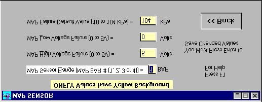
35 Coolant Sensor The CLT Sensor has limits of its capability. If the High or Low Voltage is higher or lower than the voltages entered, then it defaults to its Failure value and turns on the sensor failure display on the Monitor screen. A Coolant sensor failure also causes the Check Engine Light to blink a code 1 if a light is installed. MAT Sensor The MAT Sensor has limits of its capability. If the High or Low Voltage is higher or lower than the voltages entered, then it defaults to its Failure value and turns on the sensor failure display on the Monitor screen. A MAT sensor failure also causes the Check Engine Light to blink a code 2 if a light is installed. Map Sensor The MAP Sensor has limits of its capability. If the High or Low Voltage is higher or lower than the voltages entered, then it defaults to its Failure value and turns on the sensor failure display on the Monitor screen. A MAP sensor failure also causes the Check Engine Light to blink a code 3 if a light is installed. 35


36 EGO Sensor The EGO Sensor has limits of its capability. If the High or Low Voltage is higher or lower than the voltages entered, then it defaults to its Failure value and turns on the sensor failure display on the Monitor screen. An EGO sensor failure also causes the Check Engine Light to blink a code 4 if a light is installed. The Exhaust Gas sensor failure parameter is a function of how long the sensor senses a lean condition. The Exhaust Gas sensor may be disabled by turning the EGO function off in the EGO Parameters. TPS Sensor The TPS Sensor has limits of its capability. If the High or Low Voltage is higher or lower than the voltages entered, then it defaults to its Failure value and turns on the sensor failure display on the Monitor screen. A TPS sensor failure also causes the Check Engine Light to blink a code 5 if a light is installed. 36

37 Software Diagram This Function allows the User to choose any of the software functions from within the WinTEC3 Program. By using the keyboard or a mouse you can choose a function by highlighting the function and pressing the Enter key. Using the Keyboard, use the Up Arrow Key or Down Arrow Key to make a New Menu Selection. Use the Left Arrow Key or Right Arrow Key to Expand or Minimize a Menu Selection. If you use a mouse you still have to press the Enter key to activate the selection. Monitor Engine Functions Now there are two Engine Monitor screens available. The first is the default Analog screen that operates only in EDIT Mode and the second is a Digital screen used for the ONFLY Real Time Data System. These different screens can be chosen from the Options screen that we will discuss later. 37

38 Analog Engine Monitor Screen (Default) By selecting Monitor Engine Function in the Edit Mode, which engages the Analog Monitor Screen, you will be able to gather information necessary before starting your engine for the first time. During start up and running, this feature will allow you to watch, in real time, exactly what your engine is doing. Changes to fuel flow and ignition timing may also be made through the engine monitor screen, while the engine is running. NOTE: Some calibration values are needed for the engine monitor to display all info properly, i.e. duty cycle reference number and MAP bar number, first go to Edit a Calibration File and load a Valid BIN file, so that the monitor screen can retrieve this information. To access one of the data update fields on the Monitor Screen, press the ALT + Number key to select that field. Selecting the ALT + 1 key will automatically Set Advance to Zero or Selecting the ALT + 2 key will automatically Clear Zero Advance. Selecting the ALT + 9 key will allow the user to raise or lower the AFR OFFSET by pressing the up arrow or the down arrow. Selecting ALT + 4 allows the user to change the % of GAMA (+ or - 40%). Typing T will change the Celsius temperature scale to the Fahrenheit scale. It also converts the kpa to Hg Absolute for manifold pressure display. Typing C will toggle the EGO Sensor on and off from the Monitor Screen. By typing K will kill the Engine so that you can observe the static values of the monitor screen. Typing E while in the Monitor Screen will close the Monitor screen and bring up the Edit a Calibration File screen and it will ask for a valid BIN file. Press F1 to display Monitor Help Screen and show a list of the functions we just talked about. All percentage values must be entered as whole numbers (i.e. 100 not 1.00). Digital Engine Monitor Screen (ONFLY Mode) 38

39 The Digital Engine Monitor Screen is active only when the ONFLY option has been selected and the Monitor Engine Function screen has been selected. It is displayed centered at the top of the screen and can be moved to any location on the screen. It is always on Top of all WinTEC3 screens. As you make changes to the TEC you will able to see how a change affects the Engine in real time. Digital Engine Monitor Screen and the Task Bar. When using a Laptop at 800x600 resolution, the amount of data that is being displayed on the Digital ONFLY Monitor will over lap the Task Bar and the System Status Bar. This problem can be solved by using the higher resolution of 1024x768. If your Laptop does not have 1024x768 resolution then use the Show TaskBar and Hide TaskBar buttons to enable and disable the Task Bar as needed. Also, if the Task Bar has overlapped the Digital monitor screen, just change the focus to the Digital Monitor and the Task Bar will be overlapped by the Monitor screen. You can bring the Task Bar backup by changing focus back to the other Active screen. Use ALT+TAB to change the Focus of the currently Active Windows. Program TEC To get the TEC to respond to the changes that you have made only to the BIN file you must first Save the BIN file and then move the S19 file from your computer to the TEC by pressing the Program TEC button. Make sure the cable is connected and use this command to send your new S19 calibration file to the TEC's memory. When the S19 calibration file is loaded correctly the program will respond with PROGRAM VERIFIED. The Program TEC Option ONLY loads the S19 file and does not open a BIN file. You will always be asked to enter a New S19 file name. 39

40 Auto Calibrate VE Table The New Automatic VE Table Calibration Process can use input from either the TEC Unit as the Data Source or from a current DATALOG "DAT" File. Choose a "DAT" file from the list shown and Click on it to use that file as the data source or Click on the CONTINUE Button to use the TEC Unit Data Stream as the Data source. MAP, RPM and other settings are based on the current "BIN" File and should not be changed before the calibration is done. When the tuner enters the Auto Calibrate routine he is asked to enter a number of data points that the tuner wants to collect for each cell. The Minimum number is 5 data points. If you are using the TEC data stream you may also find that the EGO Correction (ICR) may not have started to report new correction values. This should start within 20 seconds. When the EGO Correction starts reporting new values, the Cell that is in range of the RPM and kpa as displayed to the left of the Table, will start to collect data each time that cell is hit. Keep collecting data until the cells in your query are filled and have turned Yellow. Each kpa and RPM Cell must be hit for a Programmable number of data points to calculate a new VE cell value. When you have completed the Calibration or when the End of File is reached in the "DAT" file, you can Press the SAVE button and this table will be saved as a new BIN file and can be downloaded to the TEC at a later time. If you press ESC or the << Back Button, the VE Table values are reset to their Original Values and not saved. Press F2 to recalculated the Entire table from the Original values. Use the Mouse to Click on single cell to be recalibrated from the Original value. The Auto Calibrate VE Table is not active in the ONFLY Mode. 40


41 Create a Datalog File To Save a Datalog Session on Disk, hookup the TEC to the PC, the same as for engine monitoring. Get the PC ready to start the recording session by selecting Create a Datalog File button from the main menu. The computer will ask you for a filename in which to store the data. Enter the filename and press/click the OPEN button. Now you must specify the rate at which to save the data. Select 1, 2 or 3. Speed depends on your computers clock rate and available storage but most people use 3 to get the highest resolution. Now determine how many screen repetitions you want to save. The screen repetitions should be entered in multiples of 2 (i.e. 2,10,34,82). Once initiated, data will start streaming across the screen graphically. When the line gets to the right edge of the window, it will clear and start over again. This will continue until all the repetitions you set are completed. You can use the Esc Key to end the session before you reach the Max number of repetitions. View a Datalog File You can choose from 1 to 16 of the available traces in Single Graph Format and extract exact information on each of the traces and the time that each event occurred. On the View Data Setup screen, check each of the traces that you wish to view. Low Resolution screens like 640 x 480, you may only get 6 traces to view at any one time. After the traces are displayed, you can use the arrow keys to move a time cursor around the graphs. In each box you will see the actual reading at that exact moment in time. Each of the Window graphs can be moved to different places on the screen so that you can customize your display. When you leave this routine and come back at a later time all of the graphs will be in the same position as they were in the last session. Press the F1 key to display the Help Screen with all of the Keyboard Commands. 41


42 Trace Graphs Multi Graph Overlay You can choose 2 to 4 traces in Multi Graph Overlay. This graph gives the tuner the ability to look at several graphs at one time and compare all of the traces in time synchronization. Each trace has its own scale and data display and the single line cursor can be moved just like the single graphs. Press the F1 key to display the Help Screen with all of the Keyboard Commands. Keyboard Commands Left arrow Right arrow Up arrow Down arrow Page up Page down C Home End 1 move left 1 move right 10 moves right 11 moves left moves forward one Page moves back one Page Center Start of file End of file 42


43 The EGO Correction window in View Data has been changed to Percentage Value and created a new scale based on Authority Range. Because the format has changed you will not be able to view old 'DAT' files. Authority Range was added to DAT file header for EGO Correction scaling. Options The Options Menu lets the user select Engine Monitor Type and Screen type. The Engine Monitor selections are ONFLY Real Time Editing with Digital Monitor or Standard Editing mode with Analog Monitor. Screen Type lets you select the Monitor Contrast for both Monitors of either Normal or High contrast based on the screen appearance in high sunlight conditions. DEFAULT SCREEN SETTINGS: The number of graph windows displayed at startup of View Datalog routine is determined by the size of your Monitor as shown in the table below: 640x480 = 1 to 6 graphs 800x600 = 1 to 8 graphs 1024x768 = 1 to 15 graphs 1280x1024 or greater = 1 to 16 graphs For Best Results use the small screen fonts. Software Tools Selecting the Software Tools button will bring up the WinTEC3 Software Tools menu. The Current Selections available on this menu are: Calculator The WinTEC3 Calculator has several unique features that are needed for the WinTEC3 software configuration. First, beside the common features of a standard Calculator, it can Add, Subtract, Multiply, and Divide Percents. 43
.")
44 This is needed when determining the correct advance values for the advance tables (etc). The Calculator also gives you Square Root Calculations at a touch of a button. Other fast calculations maybe added later. Memo Pad When you enter Memo Pad for the first time, you will be asked to enter a filename with the '.WMO' extension. (No need to enter the extension). After the file is opened the user will be set at the last data record to be entered. When the user finishes entering new data, pressing the Add Memo button will save the current record and then set the user to the next blank record. Any record can be deleted by selecting the record you wish to delete and pressing the 'Delete Memo' button. To move backward in the file press the 'Previous Memo' button and to move forward in the file press the 'Next Memo' button. To locate a record, press the 'Find Memo' button and enter the Date the record was created in the 01/22/99 format. The program will search from the beginning of the file to the first match found. To close the current memo file and open another Memo file, use the 'Open Memo' button. When you are ready to save the memo file and exit, press the Save/Exit button. Use the F1 key to display the Memo Help file on screen. View Software User's Guide This Selection lets the Tuner View the Text version of the "WinTEC3 Software User's Guide". It can be printed on the system local printer or viewed from within the WinTEC3 program. This should be the first file that you read when you start WinTEC3. Print Calibration File Selection of this function will allow you to print out the currently valid calibration data file. The calibration will be four pages long and if the Wizard is completed before the printout, the vehicle name field will also be printed at the top of each page. A print out of the base calibration as supplied with your software should be kept in your files for quick reference. 44

45 Interrogate BIN File The File Menu Option Interrogate BIN File allows the user to view key file data so that the user can decide if the file is the one that is needed to tune the vehicle that is currently connected to the user s PC. One helpful way of keeping track of old files is to use Long File Names. With Windows the user can give a bin file a name that is very descriptive of the kind of vehicle that the TEC unit is installed in (i.e. Ford Mustang GT 1996.bin). To Print Out a Graphics Screen Each of the Forms can now be printed from the WinTEC3 program by pressing the PRINT FORM button on each window. This feature requires a graphics capable printer connected to the PC/Laptop computer. Downloading Data Into Other Spreadsheets TEC stores the data in ASCII format that can be imported into spreadsheets. You may need to run an import or conversion utility in your spreadsheet to bring it in. The data is set up in columns with the first column being seconds. The columns are arranges as follows: The first two lines of the file are header data. Column Bytes 0-1 Byte 2 Byte 3 Byte 4 Bytes 5-6 Byte 7 Byte 8 Byte 9 Byte 10 Byte 11 Byte 12 Bytes Byte 15 Byte 16 Byte 17 Byte 18 Byte 19 Byte 20 Byte Byte Byte 25 Data = RPM Data = Advance Data = Map = Coolant = Total FPW Data = Knock Data = MAT Data = TPS Data = Battery Volts = Sensor Flags = GPO1 Data = Scaling Data = ACTUAL AFR Data = EGO Correction = Desired AFR = ARF Monitor Updates = EGO Volts = TBS Offset Data = Staged PulseWidth = PulseWidth = AD Input # 1 Data 45
R4 Engine Programming Software
 R4 Engine Programming Software Description: The R4 software is a Windows TM based software package that provides the user interface for a variety of Split Second engine management products. It controls
Table of Contents. Part I USB Communication. Part II User Interface. Part III User Settings (Tab Control) DFS-1000 Dataview. 2 File Menu.
 DFS-1000 Dataview. 2 File Menu.") 2 Table of Contents Part I USB Communication 3 1 Important... Information 3 2 Connecting... Controller 3 Part II User Interface 4 1 Overview... 4 2 File Menu... 5 3 Options... Menu 6 4 Help Menu... 6 5
2 Table of Contents Part I USB Communication 3 1 Important... Information 3 2 Connecting... Controller 3 Part II User Interface 4 1 Overview... 4 2 File Menu... 5 3 Options... Menu 6 4 Help Menu... 6 5
Table of Contents. WinTEC v4 Software User s Guide
 Table of Contents Requirements... 2 Using WinTEC v4... 3 Installing the software... 3 Configuring the software... 3 Selecting your Serial Port... 3 Changing the Dashboard appearance... 4 User Interface
ecuexplorer User Guide
 Installation...2 Getting Started...3 User Interface...3 Menu Structure...3 Initial Configuration...4 Hotkeys...4 Navigation Tree...5 User-Defined Data Items...5 Known Trouble Codes...6 Saved Log Files...7
DIRECT LINK FLASH TUNER
 DIRECT LINK FLASH TUNER Installation and User Manual Rev 3.0 This Guide is intended to answer basic Direct Link tuning questions and to act as a Quick Start Guide. It is not intended to be encyclopedic
WHIPPLE FLARE FLASH Instruction Manual
 WHIPPLE FLARE FLASH Instruction Manual 2015 AND UP Ford MUSTANG/F150 WHIPPLE SUPERCHARGERS 3292 NORTH WEBER AVE FRESNO, CA 93722 TEL 559.442.1261 FAX 559.442.4153 A color PDF of this manual is available,
WELCOME TO DYNOJET WINPV SOFTWARE
 WELCOME TO DYNOJET WINPV SOFTWARE The Software Engineers at Dynojet understand your need to attain the maximum performance from the Harley Davidson motorcycles you evaluate and tune. For this reason, they
WHIPPLE FLARE FLASH Instruction Manual
 WHIPPLE FLARE FLASH Instruction Manual 2015 AND UP Ford MUSTANG/F150 WHIPPLE SUPERCHARGERS 3292 NORTH WEBER AVE FRESNO, CA 93722 TEL 559.442.1261 FAX 559.442.4153 A color PDF of this manual is available,
Index. What is FIRESTORM? Find out on the next page. What is Mallory FIRESTORM...3. Features & Benefits...4. Dare to Compare Charts...
 BUYERS GUIDE Index What is Mallory FIRESTORM...3 Features & Benefits...4 What is FIRESTORM? Find out on the next page. Dare to Compare Charts... 5-11 How to Buy... 12-14 New Product Data Sheets...Appendix
MAP-CAL Manifold Absolute Pressure Calibration Software. Performance Motor Research Limited. Users Guide Version 2.2
 MAP-CAL Manifold Absolute Pressure Calibration Software Performance Motor Research Limited Users Guide Version 2.2 www.mapecu.com Contact: Powerhouse Racing, Inc. Ph: 817 529 4800, Fax 817 529 4801 Copyright
ecuexplorer User Guide
 Installation...2 Getting Started...3 User Interface...3 Menu Structure...3 Initial Configuration...5 Hotkeys...6 Navigation Tree...7 User-Defined Data Items...7 Known Trouble Codes...8 Saved Log Files...9
VALCON EasyWriter Ver1.0E Manual
 VALCON EasyWriter Ver1.0E Manual E05172-K00022-00 Published Dec.2010 Ver3-1.03 HKS Co., Ltd. Revision History Revision Date 2008/12/10 First Edition (Ver3-1.01) 2010/4/2 Second Edition (Ver3-1.02) 2010/12/22
Infinity V95 August 2014 Update Notes STOP! THIS PRODUCT HAS LEGAL RESTRICTIONS. READ THIS BEFORE INSTALLING/USING!
 Instruction Manual Instruction Manual Infinity V95 August 2014 Update Notes STOP! THIS PRODUCT HAS LEGAL RESTRICTIONS. READ THIS BEFORE INSTALLING/USING! THIS PRODUCT MAY BE USED SOLELY ON VEHICLES USED
Invented and Manufactured By S. Roselle Rd Schaumburg, IL Phone Fax
 Invented and Manufactured By 1411 S. Roselle Rd Schaumburg, IL 60193 Phone 847-923-0002 Fax 847-923-0004 www.altronicsinc.com During use of this system the Oxygen sensor becomes very hot. Do not touch
CENTURION Pro Diagnostic Motorcycle Scan Tool USER S GUIDE. Version 1.0
 CENTURION Pro Diagnostic Motorcycle Scan Tool USER S GUIDE Version 1.0 CHAPTER 1: Preliminaries Introduction Centurion is a user-friendly tool that can diagnose engine and system problems and perform many
Toyota MR-S & Celica User Manual Questions? Version 4:01 (13-August-03)
") Toyota MR-S & Celica User Manual http://www.fc-datalogit.co.nz Version 4:01 (13-August-03) MR-S, ZZW30, 1ZZ-FE & Celica, ZZT231, 2ZZ-GE Contents I- Introduction. FC- FC-Edit Opening page screen capture.
Toyota MR-S & Celica User Manual http://www.fc-datalogit.co.nz Version 4:01 (13-August-03) MR-S, ZZW30, 1ZZ-FE & Celica, ZZT231, 2ZZ-GE Contents I- Introduction. FC- FC-Edit Opening page screen capture.
Needless Torque Calibrations
 Needless Torque Calibrations Basic Instructions for Export/Loading tunes and Datalogging. Note: These instructions will NOT cover COM port setup or general PC skills Basic custom tune instructions: Predator/Trinity
User's Guide. For CarChip and CarChip E/X 8210 & 8220
 User's Guide TM For CarChip and CarChip E/X 8210 & 8220 Product Number: 8210, 8220 Davis Instruments Part Number: 7395.064 DriveRight CarChip User s Manual Rev A (January 2, 2003) Davis Instruments Corp.,
Bosch LSU4 Wide Band UEGO Controller
 Bosch LSU4 Wide Band UEGO Controller Part Number 220-VM-AF1 CONFIGURATION Module Type: AF1 Serial Number: Output Units: Lambda A/F Gasoline A/F Methanol Channel Name: A/F Cyl 1 Channel Options: V_Net ID:
OBDI RT Tuner Quick Start Guide
 OBDI RT Tuner Quick Start Guide Revision A Page 1 Table of Contents Introduction...3 Minimum PC Requirements...3 Program Installation...3 Registering the Program...4 Select the Desired ECM Definition Files...6
Podium Data Analysis Software. User Manual. SWIS10 Version
 SWIS10 Version Issue 1.00 March 2003 Contents 1 Introduction 5 1.1 What is Podium? 5 1.2 About This Manual 5 1.3 Typographical Conventions 6 1.4 Getting Technical Support 6 2 Getting Started 7 2.1 System
06 YZF-R6. The Performance Edge. FI MATCHING SYSTEM INSTRUCTION MANUAL Ver1.11. for excellent riders
 06 YZF-R6 FI MATCHING SYSTEM INSTRUCTION MANUAL Ver1.11 The Performance Edge for excellent riders CONTENTS 1 Introduction... 1 1 1 Objective... 1 1 2 Recommended operation environment for the personal
Soft-Engine - Data store software: Version 8
 Soft-Engine - Data store software: Version 8 Software description INERTIAL 8 BRAKER 8 is a new generation software for dynamometers. This is very a very and very performant software, but easy to use. Braker
Installation Instructions
 Installation Instructions USM 4 Sensor Input Vnet Module Racepak PN: 230-VM-USM Racepak Data Systems 30402 Esperanza Rancho Santa Margarita, CA 92688 949-709-5555 www.racepak.com Table of Contents PRODUCT
Display & Log Unit. Mikael Larsmark. November 22, 2006
 Display & Log Unit Mikael Larsmark November 22, 2006 1 Contents 1 Introduction 3 2 Installation 4 2.1 Hardware.................................... 4 2.2 Software..................................... 4
Procom PPC Software User s Manual
 Procom PPC Software User s Manual Version 1.1 Procom Engineering Inc. 66 Maxwell, Irvine, CA 92618, USA Tel: 949-748 6338 Fax: 949-748 6339 Email: info@procomengineering.com www.procomengineering.com Contents
ECUTEK ON NISSAN 370Z/G37
 ECUTEK ON NISSAN 370Z/G37 INTRODUCTION Welcome and thank you for being a customer of Visconti Tuning! This guide is broken into sections which you can jump around between by clicking on each of the chapters
S&S Cycle ProTune II
 S&S Cycle ProTune II User Manual Contents 3 Table of Contents Foreword 0 Installation 7 1 System Requirements... 7 2 Installation... 7 3 Manual USB Device... Driver Installation 9 Windows XP Windows Vista
Professional EFI Systems Product Catalog
 Professional EFI Systems Product Catalog Table of Contents: Section 1: ECU Options 2-8 Section 2: Various Sensors and Switches 9-14 Section 3: Display Options 15 Section 4: CAN Communication Cable 16 Section
ARES. User s Guide. Aprilia Racing Engine Setup. English version
 ARES Aprilia Racing Engine Setup User s Guide English version ARES user s guide 2/59 I. WARNINGS... 6 II. SOFTWARE AND ENGINE CONFIGURATION COMPATIBILITY... 6 III. BEFORE UPDATING ARES TO A NEWER VERSION...
Version 2.031, Firmware doesn't contain all listed features and fixes is the proper one
 Version 2.035, 29-03-2017 Bug from versions 2.030 2.034 with pullups when BT CAN stream enabled fixed, Gear detection bug fixed 1JZ/2JZ CAM#2 support added for faster synchronization For ALS pedal position
CH1. Figure 1: M3 LOG Advanced
 TECHNICAL DOCUMENTATION 03/09/2003 GAUGE Notes: M3 LOG Advanced technical documentation, dimensions and pinout. Ver 1.05 M3 LOG Advanced Internal lateral accelerometer CH1 Beacon Speed COM Power CH2 CH3
Instructions & Software Install Version 6.30a (Feb 2018) Copyright 2018 DealerTool.co.uk
 Copyright 2018 DealerTool.co.uk") DealerTool Instructions & Software Install Version 6.30a (Feb 2018) Copyright 2018 DealerTool.co.uk If you have any problems please email support@dealertool.co.uk Emails will always be responded to within
DealerTool Instructions & Software Install Version 6.30a (Feb 2018) Copyright 2018 DealerTool.co.uk If you have any problems please email support@dealertool.co.uk Emails will always be responded to within
Wagner Smart Screen Service/Troubleshooting Screens
 Section 7-2 Wagner Smart Screen Service/Troubleshooting Screens Menu Button PIN code login When you fi rst click on the Menu button, you will be prompted for a PIN code. Enter 0070 and click the check
DOS SMT MANUAL OPERATORS MANUAL FOR DOS VERSION OF SMT. Index 1. SOFTWARE INSTALLATION SCREEN EXPLANATIONS CONNECTING TO THE SMT 9-11
 DOS SMT MANUAL OPERATORS MANUAL FOR DOS VERSION OF SMT Index Page no: 1. SOFTWARE INSTALLATION 1-2 2. SCREEN EXPLANATIONS 3-8 3. CONNECTING TO THE SMT 9-11 4. TUNING COMMANDS 12 5. SETTING THE ANALOG DEFLECTION
1510A. MTI Instruments, Inc. 325 Washington Avenue Extension, Albany, New York USA Phone: (518) FAX: (518)
 FAX: (518)") Revision 3.1 August 7, 2014 1510A Precision Signal Source Note: Performing a user calibration with the software package will result in an accuracy of 2% at best. A factory cal is required to achieve the
Revision 3.1 August 7, 2014 1510A Precision Signal Source Note: Performing a user calibration with the software package will result in an accuracy of 2% at best. A factory cal is required to achieve the
Operator s Manual. Morbark Integrated Control System Woodhog Series Model 2600
 Operator s Manual Morbark Integrated Control System Woodhog Series Model 2600 Contents Introduction 4 Parts Identification 6 Display Module Display Pages 9 Main Page 11 Engine Information Page 12 Hydraulic
EVC EasyWriter Manual
 EVC EasyWriter Manual Revision History Revision Date 2007/3/30 Create New(Ver3-1.01) Contents 2009/2/24 Instructions for the Lancer Evolution X are added.(ver3-1.02) E05122-K00041-00 Published February.2009
Version 2.063b, D tables bug introduced in version fixed
 Version 2.066, 02-03-2018 FIAT 500 reverse gear information send over CAN (hill holder bug fixed). The reverse gear switch should be connected to the switch 1 input Version 2.065, 02-03-2018 Astra VRX
WHIPPLE FLARE FLASH INSTRUCTION MANUAL
 WHIPPLE FLARE FLASH INSTRUCTION MANUAL 2015 AND UP FORD MUSTANG WHIPPLE SUPERCHARGERS 3292 NORTH WEBER AVE FRESNO, CA 93722 TEL 559.442.1261 FAX 559.442.4153 A color PDF of this manual is available, email
User Guide. Subaru Turbo (North American Models)
") User Guide Subaru Turbo (North American Models) Page 2 Table of Contents Product Introduction 4 Supported Vehicle List 4 In-Box Contents 5 What Is A Map? 7 AccessPORT Installation 8 Pre-Installation 8
User Guide Subaru Turbo (North American Models) Page 2 Table of Contents Product Introduction 4 Supported Vehicle List 4 In-Box Contents 5 What Is A Map? 7 AccessPORT Installation 8 Pre-Installation 8
Controller Pro Instruction Manual
 Controller Pro Instruction Manual These instructions cover: Installing Controller Pro Programming Troubleshooting Doc# Doc120-017 Revision: D ECO: 102208 Note: Document revision history and EC information
TOF-Watch SX Monitor
 TOF-Watch SX Monitor User manual Version 1.2 Organon (Ireland) Ltd. Drynam Road Swords Co. Dublin Ireland Contents General information... 3 Getting started... 3 File Window... 7 File Menu... 10 File Open
CurveMaker HD v1.0 Dyna 2000 Programmable Ignition programming software
 Contents CurveMaker HD v1.0 Dyna 2000 Programmable Ignition programming software Dynatek 164 S. Valencia St. Glendora, CA 91741 phone (626)963-1669 fax (626)963-7399 page 1) Installation 1 2) Overview
CAUTION: CAREFULLY READ INSTRUCTIONS BEFORE PROCEEDING.
 Twin Tec User Instructions for CAUTION: CAREFULLY READ INSTRUCTIONS BEFORE PROCEEDING. OVERVIEW The is 50 states street legal (ARB E.O. No. D-641) for 2001-2008 H-D Twin Cam models with the 36 pin Delphi
CAUTION: CAREFULLY READ INSTRUCTIONS BEFORE PROCEEDING. NOT LEGAL FOR SALE OR USE IN CALIFORNIA OR ON ANY POLLUTION CONTROLLED VEHICLES.
 Twin Tec User Instructions for Software CAUTION: CAREFULLY READ INSTRUCTIONS BEFORE PROCEEDING. NOT LEGAL FOR SALE OR USE IN CALIFORNIA OR ON ANY POLLUTION CONTROLLED VEHICLES. OVERVIEW software runs under
Controller Pro Instruction Manual
 Controller Pro Instruction Manual These instructions cover: Installing Controller Pro Programming Troubleshooting Doc# Doc120-017 Revision: B ECO: 010507 Note: Document revision history and EC information
Race Studio 2. Race Studio 2 Configuration User s manual. Race Studio Configuration: user s manual 1
 Race Studio 2 Race Studio 2 Configuration User s manual Race Studio Configuration: user s manual 1 AIM s.r.l. reserves the right to make changes in the content of this manual without obligation to notify
USER MANUAL UPDATED
 USER MANUAL UPDATED 4-19-18 Thank you for purchasing the CAN-EGT interface! Monitoring exhaust gas temperatures in real time, cylinder-by-cylinder, means more accurate air-fuel targets, prevention of catastrophic
CAN-EGT by DIYAutoTune.com
 CAN-EGT by DIYAutoTune.com February 7, 2013 1 Introduction The first question you may have is, Why have a special board for EGT sensors? Many other sensors can be wired straight to a MegaSquirt, including
Syvecs Limited. Syvecs S6 GP. SSuite Basic Manual. Ryan Griffiths
 1 Syvecs Limited Syvecs S6 GP SSuite Basic Manual Ryan Griffiths 24-10-2011 This document intended for use by a technical audience and describes a number of procedures that are potentially hazardous. Installations
MS3-PNP version Toyota Supra 1JZ-GTE / 7M-GTE. User Manual for MS3-PNP version 2 only
 MS3-PNP version 2 1989-1992 Toyota Supra 1JZ-GTE / 7M-GTE User Manual for MS3-PNP version 2 only Table of content Installation of TunerStudio and MegaLogViewer (for Windows, Mac and Linux)... 3 Software
An ISO 9001:2008 Registered Company
 An ISO 9001:2008 Registered Company Upfitter Interface Module The following list represents firmware v4.30 A-UIM4-506-A 2011-2016 Ford F250-550 B-UIM4-506-A 2017 F250-F550 A-UIM4-751-A 2013-2017 1500-5500
Instruction and Operations Manual
 1 GARTECH Enterprises, Inc. Rev 2 01-23-09 Instruction and Operations Manual Portable Test Cell Overview The primary purpose of the Portable Test Cell is to allow the user the ability to control the engine
Service Bulletin SB685. Date: 8/18/2017 TriPac EVOLUTION Communications Update Bulletin Location: TSA Info Central\Service Bulletins
 Service Bulletin SB685 Date: 8/18/2017 Subject: TriPac EVOLUTION Communications Update Bulletin Location: TSA Info Central\Service Bulletins Units: All TriPac EVOLUTION Summary: This bulletin updates and
PLEASE CHECK YOUR LAMBDA TABLES AFTER UPGRADE!
 Version 2.071, 24-04-2018 Gear calculation strategy rewritten. Now tolerance means percentage of ratio to the next gear ratio. Gear detection delay added Alternator control signal can be inverted Boost
Instruction Manual for BE-SP3 Circuit. 10/21/07
 Page 1 of 54 Instruction Manual for BE-SP3 Circuit. 10/21/07 Page 1 Index: Page 2 BE-SP3 Circuit Specifications. Page 3-4 Intro to the BE-SP3. Page 5 Basics of serial to parallel. Page 6-7 ASCII Code.
LCU-ONE CAN connected to MXL QM and EVO3 QM User Manual
 LCU-ONE CAN connected to MXL QM and EVO3 QM INDEX Chapter 1 LCU ONE... 2 1.1 Part number... 2 Chapter 2 LCU ONE and Lambda probe mounting... 3 Chapter 3 Connection to MXL EVO3 QM... 5 3.1 LCU-ONE CAN Connection...
The uscope Getting started
 Introduction (fw 5.11) AES uscope Manual The uscope Getting started The uscope! A single channel, pocket-sized, digital storage oscilloscope that s small, quick, and powerful. Automotive presets get you
Subject: 1999 Nissan Maxima A32, VQ30DE, USA OBD2 Compliant, Consult Data Registers
 Subject: 1999 Nissan Maxima A32, VQ30DE, USA OBD2 Compliant, Consult Data Registers This vehicle has a J1962F 16 pin OBD2 connector as well as a 14 pin Consult connector for data communication ports to
Software Program User Manual
 2MPro Sign Software Version 2.13 3/18/2004 Page 1 2MPRO Software Program User Manual Software License Agreement This Software was Written Specifically for use on predetermined signs and is not intended
Osiris User Guide. Page 1 of 23
 Page 1 of 23 Contents 1 - Software Installation... 3 2 - Preparation and Precautions before flashing an ECU... 3 3 - Reflashing an ECU with Osiris Reflasher... 4 4 - Using the UpRev map switching feature
User s Guide for UTCIS Engine Management Software
 User s Guide for. Rev. 1.0 1 Printed in the U.S.A. Copyright 2008 All Rights Reserved. NOTICE REGARDING WARRANTIES The UnwiredTools comes with no Warranty. With regard to this Manual and the information
USER GUIDE. Tolomatic Motion Interface (TMI) Actuator Control Solutions for: ACS Stepper Drive/Controller Tolomatic Electric Linear Actuators
 Actuator Control Solutions for: ACS Stepper Drive/Controller Tolomatic Electric Linear Actuators") USER GUIDE Tolomatic Motion Interface (TMI) Actuator Control Solutions for: ACS Stepper Drive/Controller Tolomatic Electric Linear Actuators 3600-4167_01_TMI_Gui LINEAR SOLUTIONS MADE EASY Tolomatic reserves
USER GUIDE Tolomatic Motion Interface (TMI) Actuator Control Solutions for: ACS Stepper Drive/Controller Tolomatic Electric Linear Actuators 3600-4167_01_TMI_Gui LINEAR SOLUTIONS MADE EASY Tolomatic reserves
Cascade Configuration Tool
 Cascade Configuration Tool Version 1.0.10 Installation and Operations Manual 00-02-0724 01-25-11 Section 40 In order to consistently bring you the highest quality, full featured products, we reserve the
WARNING!!!!!!!!! IMPORTANT INFORMATION: READ BEFORE INSTALLATION!
 V_Net Relay Module Installation Instructions: Part Number: 230-VM-RELAY WARNING!!!!!!!!! IMPORTANT INFORMATION: READ BEFORE INSTALLATION! The relay outputs of the 230-VM-RELAY module may turn on when not
RIVA / Athena Pro-Series ECU
 RIVA / Athena Pro-Series ECU USING SOFTWARE (MAYA) Running Maya for First Time Once installed, Maya is available in the Start menu under Programs -> Maya, or from a desktop short cut, if created. The first
Megajolt Lite Jr. Controller API Documentation Version 4.x.x
 Megajolt Lite Jr. Controller API Documentation Version 4.x.x Copyright 2004-2008 Autosport Labs http://www.autosportlabs.net Revision 1: 10 Jan 2007 Revision 2: 11 Jan 2007 (version 3.2.x) Revision 3:
SDL User s Manual. Contents. Introduction... 1 Overview Installation Sport Dash Manager Software... 23
 MoTeC SDL User s Manual Contents Introduction... 1 Overview... 2 Display...2 Alarms...5 Data Logging...5 Other Functions...7 Measurement Inputs...8 Auxiliary Outputs...12 Communications Overview...13 ECU
COPYRIGHTED MATERIAL. Making Excel More Efficient
 Making Excel More Efficient If you find yourself spending a major part of your day working with Excel, you can make those chores go faster and so make your overall work life more productive by making Excel
ECUTEK ON NISSAN JUKE TURBO
 ECUTEK ON NISSAN JUKE TURBO INTRODUCTION Welcome and thank you for being a customer of Visconti Tuning! This guide is broken into sections which you can jump around between by clicking on each of the chapters
SUPERSCAN II. Always a step ahead.
 SUPERSCAN II Always a step ahead. Operations Manual DEC Automotive Pedro Lozano 4453 Capital Federal C 1417 EEY Argentina Telephone +54 11 4567 1188 / 3994 Fax +54 11 4639 8643 http://www.decautomotive.net/
Megasquirt Plug and Play Toyota Supra 1JZ-GTE / 7M-GTE
 Megasquirt Plug and Play Toyota Supra 1JZ-GTE / 7M-GTE User Manual Table of content Steps to install the Megasquirt Plug and Play ECU... 4 1. Installation of TunerStudio and MegaLogViewer (for Windows,
PocketLOGGER for. For use exclusively with Rtek7 Stage 2 ECU Upgrade. Instruction Guide
 PocketLOGGER for For use exclusively with Rtek7 Stage 2 ECU Upgrade Instruction Guide Rtek Firmware N332 Ver 1.1.2 N326 Ver 1.0.0 N351 Ver 1.0.0 PocketLOGGER Ver 2.0.0 digital tuning, inc. 23021 N. 15
Tach Facts V3.0 Software
 Tach Facts V3.0 Software Download runs from your Auto Meter Playback Tach with Tach-Facts Software. Instr. No. 2650-978 Tach Facts provides complete race analysis on your personal computer. Introduction
Troubleshooter Quick Reference Guide
 Troubleshooter Quick Reference Guide March 2008 EAZ0025B29B Rev. C Trademarks Acknowledgement Snap-on, Scanner, and Fast-Track are trademarks of Snap-on Incorporated. All other marks are trademarks of
Apex Turbo / Supercharger EFI Control Box Instructions
 Apex Turbo / Supercharger EFI Control Box Instructions Before you begin, please read all the instructions below and check kit contents. Control Box Kit Contents: Quality check by: 1 Control Box with EFI
Podium Data Analysis Software. User Manual. RCA40 Version
 RCA40 Version Issue 1.00 March 2003 Contents 1 Introduction 5 1.1 What is Podium? 5 1.2 About This Manual 5 1.3 Typographical Conventions 6 1.4 Getting Technical Support 6 2 Getting Started 7 2.1 System
Options. Parts List. Optional Expansion Hub Optional Ignition Module Optional Memory Card
 Options Optional Expansion Hub Optional Ignition Module Optional Memory Card View boost, speed, and gear on the LCD Display. View the ignition changes on the LCD Display. Log and store map data. Card storage
V5 Build 100 SOFTWARE AND FIRMWARE UPDATES
 V5 Build 100 SOFTWARE AND FIRMWARE UPDATES Who should update: It is recommended that any user update to this latest version of software and firmware. There are improvements to laptop communication speeds
Screen Designer. The Power of Ultimate Design. 43-TV GLO Issue 2 01/01 UK
 Screen Designer The Power of Ultimate Design 43-TV-25-13 GLO Issue 2 01/01 UK 43-TV-25-13 GLO Issue 2 01/01 UK Table of Contents Table of Contents Honeywell Screen Designer - The Power of Ultimate Design
Table of Contents. Table of Contents
 Table of Contents Table of Contents Introduction... 3 Installing a V Series Data Logger... 5 Getting acquainted with your V Series Logger System... 5 The Data Loggers... 5 The System Components... 6 Planning
The uscope Getting started
 Introduction (fw 6.01) The uscope Getting started The uscope! A single channel, pocket-sized, digital storage oscilloscope that s small, quick, and powerful. Automotive presets get you going quickly. Ideal
IRF90 - Rotating Focuser
 IRF90 - Rotating Focuser Part # 600180 REV092111 Page 1 Contents Introduction and Overview... 3 Limitations... 3 Packing List... 4 Installation... 5 Remove Existing Focuser... 5 Installing the Rotating
ECUTEK ON INFINITI VR30
 ECUTEK ON INFINITI VR30 INTRODUCTION Welcome and thank you for being a customer of Visconti Tuning! This guide is broken into sections which you can jump around between by clicking on each of the chapters
Abstract. GLV User Manual 1
 GLV User Manual 1 Abstract This user manual is a high level document that explains all operational procedures and techniques needed to operate the GLV system in a safe and effective manner. Anyone operating
Software designed to work seamlessly with your CNC Masters machine. Made to work with Windows PC. Works with standard USB
 Software designed to work seamlessly with your CNC Masters machine Made to work with Windows PC Works with standard USB Clutter free interface. The software is engineered for the machine so you don t have
The Fundamentals. Document Basics
 3 The Fundamentals Opening a Program... 3 Similarities in All Programs... 3 It's On Now What?...4 Making things easier to see.. 4 Adjusting Text Size.....4 My Computer. 4 Control Panel... 5 Accessibility
Component Tests User Manual
 Component Tests User Manual February 2009 ZEEMS308G Rev. C Trademarks Acknowledgements Snap-on, Scanner, Fast-Track, and MODIS are trademarks of Snap-on Incorporated. All other marks are trademarks or
M2500 Engine Controller Configuration Manual
 M2500 Engine Controller Configuration Manual Revision: 08-04-2011 Page 1 Contents 1 Preface... 4 2 Configuration from front panel... 5 2.1 Engine Controller Configuration... 6 2.1.1 RPM settings... 6 2.1.2
INTRODUCTION. Warning: it is strongly recommended to always verify whether the ECU needs specific software settings to export data.
 Link G4 ECU INTRODUCTION AIM has developed special applications for many of the most common ECUs: by special applications we mean user-friendly systems which allow to easily connect your ECU to our hi-tech
Podium Plus Data Analysis Software. User Manual. SWIS10 Version
 SWIS10 Version Issue 1.10 February 2005 Contents 1 Introduction 6 1.1 What is Podium Plus? 6 1.2 About This Manual 6 1.3 Typographical Conventions 7 1.4 Getting Technical Support 7 2 Getting Started 8
Figure 1 Wide-Band Oxygen Sensor Connectors
 Twin Tec TCFI III and ThunderMax Comparison INSTALLATION The Twin TEC TCFI III system includes the TCFI III engine control module (ECM) and a separate WEGO IIID wideband oxygen sensor interface. The TCFI
Copyright 2004, Mighty Computer Services
 EZ-GRAPH DATABASE PROGRAM MANUAL Copyright 2004, Mighty Computer Services The Table of Contents is located at the end of this document. I. Purpose EZ-Graph Database makes it easy to draw and maintain basic
Automotive Dynamometer
 Automotive Dynamometer hardware and software DynoWaRe Rt DYNAMOMETER HARDWARE DynoWare rt THe next GeneraTion of DynoJeT DynamomeTer electronics and software Has arrived. DynoWare RT is the next generation
Plug and Play FT500 Harness. Installation and Operation Guide
 Plug and Play FT500 Harness Installation and Operation Guide PRO wiring harness 1. Index 2. Presentation... 4 3. Warranty terms... 5 4. Specifications:... 6 5. Overview... 7 5.1 PRO16 Wiring harness...
FERGUSON BEAUREGARD. RTU-5000 Configurator User Manual
 FERGUSON BEAUREGARD RTU-5000 Configurator User Manual FERGUSON BEAUREGARD RTU-5000 Configurator User Manual The Ferguson Beauregard RTU-5000 Configurator program and manuals are Copyright 1997-2004 by
Commander User Manual Version 1.1
 Commander User Manual Version 1.1-1- Welcome Commander is a device control program for the E-Stim Systems Series 2B. This program allows you to directly control your 2B from a PC via the USB connection.
Vi-PEC V44 and V88 ECU
 Vi-PEC V44 and V88 ECU Vi-PEC V44 and V88 ECU INTRODUCTION AIM has developed special applications for many of the most common ECUs: by special applications we mean user-friendly systems which allow to
Z Automotive Programming Utility (ZPU) User s Guide (version 1.3.7)
 User s Guide (version 1.3.7)") Z Automotive Programming Utility (ZPU) User s Guide (version 1.3.7) The Z automotive Programming Utility is a PC application used for configuration and firmware updates on Z Automotive products. 1: Installation
Z Automotive Programming Utility (ZPU) User s Guide (version 1.3.7) The Z automotive Programming Utility is a PC application used for configuration and firmware updates on Z Automotive products. 1: Installation